

Page 1

ThinkServerRD340
UserGuideandHardwareMaintenance
Manual
MachineTypes:70A8,70A9,70AA,70AB,70AC,and70AD
Page 2

Note:Beforeusingtheinformationandtheproductitsupports,besuretoreadandunderstandthefollowing:
•TheReadMeFirstthatcomeswithyourproduct
•“Safetyinformation”onpageiii
•AppendixA“Notices”onpage187
SecondEdition(May2014)
©CopyrightLenovo2013,2014.
LIMITEDANDRESTRICTEDRIGHTSNOTICE:IfdataorsoftwareisdeliveredpursuantaGeneralServicesAdministration
“GSA”contract,use,reproduction,ordisclosureissubjecttorestrictionssetforthinContractNo.GS-35F-05925.
Page 3

Contents
Safetyinformation..........iii
Productsthatarenotassessed.........x
Chapter1.Generalinformation.....1
Introduction.................1
Serverdocumentation.............2
Chapter2.Serversetuproadmap...5
Chapter3.Productoverview......7
Serverpackage...............7
Features..................7
Specifications...............11
Software.................11
ThinkServerEasyStartup.........12
ThinkServerEasyUpdateFirmwareUpdater.12
LenovoThinkServerEasyManage.....12
BIOSandTMMupdateutilities......12
RAIDconfigurationutilities........12
Remotemanagementsoftware......12
ThinkServerSmartGridTechnology....12
Diagnosticprograms..........13
Locations.................13
Machinetype,model,andserialnumber
label.................13
Frontviewoftheserver.........15
Frontpanel..............19
IntelligentDiagnosticsModule.......22
Rearviewoftheserver.........23
Servercomponents...........25
Hot-swaphard-disk-drivestatusLEDs...30
RAIDcard...............30
Hot-swaphard-disk-drivebackplane....33
Connectingthecables..........36
Systemboardcomponents........38
Systemboardjumpersandswitches....42
SystemboardLEDs...........46
Chapter4.T urningonandturningoff
theserver...............49
Turningontheserver............49
Turningofftheserver............49
Chapter5.Configuringtheserver..51
UsingtheSetupUtilityprogram........51
StartingtheSetupUtilityprogram.....51
ViewinginformationintheSetupUtility
program...............51
SetupUtilityprograminterface......52
Settingthesystemdateandtime.....54
Usingpasswords............55
Selectingastartupdevice........56
ConfiguringtheTPMfunction.......56
SettingthemodeoftheEthernetconnectors.57
ExitingtheSetupUtilityprogram......57
UpdatingorrecoveringtheBIOS......58
UsingtheThinkServerEasyStartupprogram...59
FeaturesoftheThinkServerEasyStartup
program...............60
StartingtheThinkServerEasyStartup
program...............60
UsingtheThinkServerEasyStartupprogram
onaWindowsoperatingsystem......62
ConfiguringRAID..............62
AboutRAID..............63
ConfiguringRAIDusingtheThinkServer
EasyStartupprogram..........64
ConfiguringtheThinkServerRAID300...64
ConfiguringtheadvancedSATA/SAShardware
RAID.................70
ConfiguringtheEthernetcontrollers......70
Updatingthefirmware............71
UsingtheFirmwareUpdaterprogram....71
UsingtheLenovoThinkServerEasyManage
program.................71
Chapter6.Installing,removing,or
replacinghardware..........73
Guidelines................73
Precautions..............73
Handlingstatic-sensitivedevices.....74
Systemreliabilityguidelines........75
Workinginsidetheserverwiththepoweron.75
Removingtheservercover..........75
Installing,removing,orreplacinghardware...77
Removingandreinstallingtherackhandles.77
Removingandreinstallingthecooling
shroud................79
Installingorremovingamemorymodule...81
InstallingorremovingtheEthernetcard...87
InstallingorremovingtheRAIDcard....90
InstallingorremovingtheThinkServerRAID
500UpgradeKeyforAdvancedRAID....95
InstallingorremovingtheThinkServerRAID
700Battery..............98
InstallingorremovingtheThinkServerRAID
300UpgradeKeyforAdvancedRAID....101
©CopyrightLenovo2013,2014
i
Page 4

InstallingorremovingtheThinkServer
ManagementModulePremium......105
InstallingorremovingtheThinkServerTrusted
PlatformModule............108
Installingorreplacingahot-swapredundant
powersupply.............111
Installingorreplacingaheatsink......115
Installingorreplacingthemicroprocessor..118
Installingorreplacingahot-swapharddisk
drive.................127
Installingorreplacinga2.5-inchsolid-state
drive.................131
Installingorreplacingtheopticaldrive...138
Installinganexternaltapedrive......144
ReplacingthePCIExpresssolid-state
drive.................145
ReplacingtheThinkServerRAIDSuper
CapacitorModule............147
Replacingthehot-swaphard-disk-drive
backplane...............150
ReplacingtheIntelligentDiagnostics
Module................154
Replacingasystemfan.........156
Replacingthefrontpanelboard......158
Replacingtherisercardassembly1....160
Replacingthecoin-cellbattery......162
Replacingthesystemboard.......164
Completingthepartsreplacement.......170
Reinstallingtheservercoverandreconnecting
cables................171
Updatingtheserverconfiguration.....175
Chapter7.T roubleshootingand
diagnostics.............177
Troubleshootingprocedure..........177
ViewingthestatusanddiagnosticLEDs.....177
Usingadiagnosticprogram.........178
Viewingthesystemeventlog.........178
Basictroubleshootingtables.........178
ThinkServerEasyStartupprogram
problems...............178
Opticaldriveproblems..........179
Hard-disk-driveproblems........180
Memorymoduleproblems........181
Keyboard,mouse,andUSBdevice
problems...............182
Chapter8.Gettinginformation,help,
andservice.............183
Informationresources............183
Usingthedocumentation.........183
ThinkServerWebsite..........183
LenovoSupportWebsite.........183
Helpandservice..............184
Beforeyoucall.............184
Callingforservice............184
Usingotherservices..........185
Purchasingadditionalservices......185
AppendixA.Notices.........187
Trademarks................188
Importantnotes..............188
Particulatecontamination..........188
PolyvinylChloride(PVC)cableandcordnotice..189
Recyclinginformation............189
Batteryreturnprogram..........189
Requirementforbatteriescontaining
perchlorate..............190
ImportantWEEEinformation.........190
EuropeanUnionRoHS...........191
GermanOrdinanceforWorkglossstatement...191
Exportclassificationnotice..........191
Electronicemissionnotices..........191
FederalCommunicationsCommission(FCC)
Statement...............191
Eurasiancompliancemark..........193
ENERGYSTARmodelinformation.......193
Index.................195
iiThinkServerRD340UserGuideandHardwareMaintenanceManual
Page 5
Safetyinformation
Note:Beforeusingtheproduct,besuretoreadandunderstandthemultilingualsafetyinstructionsonthe
documentationDVDthatcomeswiththeproduct.
Antesdeusaroproduto,leiaeentendaasinstruçõesdesegurançamultilínguesnoDVDdedocumentação
queoacompanha.
Предидаизползватетозипродукт,задължителнопрочететеивникнетевмногоезичнитеинструкции
забезопасноствDVDдискасдокументация,койтосепредоставяспродукта.
PrijeupotrebeovogproizvodaobaveznopročitajtevišejezičnesigurnosneuputekojesenalazenaDVD-us
dokumentacijomkojidobivateuzproizvod.
PředpoužitímproduktujetřebasipřečístaporozumětbezpečnostnímpokynůmuvedenýmnadiskuDVDs
dokumentací,kterýjedodávánsproduktem.
Førdubrugerproduktet,skaldusørgeforatlæseogforstådesikkerhedsforskrifter,derfindespåflere
sprog,pådendokumentations-dvd,derfølgermedproduktet.
LuetuotteenmukanatoimitetullaDVD-tietolevylläolevatmonikielisetturvaohjeetennentämäntuotteen
käyttöä.
Avantd'utiliserleproduit,veillezàbienlireetcomprendrelesinstructionsdesécuritémultilinguesfigurant
surleDVDdedocumentationfourniavecleproduit.
Πρινχρησιμοποιήσετετοπροϊόν,βεβαιωθείτεότιέχετεδιαβάσεικαικατανοήσειτιςοδηγίεςασφάλειας,οι
οποίεςείναιδιαθέσιμεςσεδιάφορεςγλώσσεςστοDVDτεκμηρίωσηςπουσυνοδεύειτοπροϊόν.
VorVerwendungdesProduktssolltenSieunbedingtdiemehrsprachigenSicherheitsanweisungenaufder
Dokumentations-DVDlesen,dieimLieferumfangdesProduktsenthaltenist.
AtermékhasználataelőttmindenképpenolvassaelésértelmezzeatermékhezkapottdokumentációsDVD
lemezentalálható,többnyelvenelolvashatóbiztonságielőírásokat.
Primadiutilizzareilprodotto,accertarsidileggereecomprendereleinformazionisullasicurezzamultilingue
disponibilisulDVDdidocumentazionefornitoconilprodotto.
製品をご使用になる前に、製品に付属のDocumentationDVDに収録されているマルチリンガルの「安
全に正しくご使用いただくために」を読んで理解してください。
제품을사용하기전에제품과함께제공되는문서DVD의다국어안전지침을주의깊게읽어보십시오.
Voordatuhetproductgebruikt,moetuervoorzorgendatudemeertaligeveiligheidsinstructiesopde
documentatie-dvdvanhetproducthebtgelezenenbegrijpt.
©CopyrightLenovo2013,2014
iii
Page 6

Przedskorzystaniemzproduktunależyzapoznaćsięzwielojęzycznymiinstrukcjamibezpieczeństwa
znajdującymisięnapłycieDVDzdokumentacjądostarczonąwrazzproduktem.
Antesdeutilizaroproduto,leiaatentamenteasinstruçõesdesegurançamultilinguesqueconstamno
DVDdedocumentaçãofornecidocomoproduto.
Înaintedeautilizaprodusul,asiguraţi-văcăaţicititşiînţelesinstrucţiuniledesiguranţăînmaimultelimbide
peDVD-ulcudocumentaţiecareînsoţeşteprodusul.
Førdubrukerproduktet,måduleseogforstådenflerspråkligesikkerhetsinformasjonenpåDVDenmed
dokumentasjonsomfølgermedproduktet.
Преждечемиспользоватьэтотпродукт ,внимательноознакомьтесьсинструкциямипотехнике
безопасностинаразныхязыках,которыеможнонайтинаDVD-дискесдокументациейвкомплектес
продуктом.
在使用本产品之前,请务必先阅读和了解产品附带的文档DVD中的多语言安全说明。
Prenegotoupotrebiteproizvodobaveznopaljivoproitajteiprouiteviejezikouputstvozabezbednostna
dokumentacionomDVD-ukojistedobiliuzproizvod.
PredpouvanmproduktusipretajteviacjazynbezpenostnpokynynadiskuDVDsdokumentcioudodanoms
produktom.
Predenzačneteuporabljatiizdelek,jepomembno,daprebereteinrazumetevečjezičnavarnostnanavodila
naDVD-juzdokumentacijo,kistegaprejeliskupajzizdelkom.
Antesdeutilizarelproducto,asegúresedeleerycomprenderlasinstruccionesdeseguridadmultilingüesdel
DVDdedocumentaciónqueseproporcionaconelproducto.
Varnogamedattläsasäkerhetsinstruktionernapådokumentations-DVD-skivansomföljermedprodukten
innandubörjaranvändaprodukten.
使用本產品之前,請務必閱讀並瞭解產品隨附的文件DVD上的多國語言版本安全資訊。
Buürünükullanmadanönce,ürünlebirliktegönderilenbelgeDVD'siüzerindekiçokdiliçerengüvenlik
yönergeleriniokuyupanladýðýnýzdaneminolun.
Передвикористаннямцьогопродуктууважноознайомтесязінструкціямизтехнікибезпекинарізних
мовах,щоможназнайтинаDVD-дискуздокументацієювкомплектізпродуктом.
Important:Fortranslatedversionsofthecautionordangerstatement,refertotheSafety,Warranty,and
SupportInformationdocument.
Ensurethatyoureadandunderstandallcautionanddangerstatementsinthisdocumentbeforeyouperform
theprocedures.Readandunderstandanyadditionalsafetyinformationthatisincludedwiththeserveror
optionaldevicebeforeyouinstall,remove,orreplacethedevice.
ivThinkServerRD340UserGuideandHardwareMaintenanceManual
Page 7
Statement1
DANGER
Electricalcurrentfrompower,telephone,andcommunicationcablesishazardous.
Toavoidashockhazard:
•Donotconnectordisconnectanycablesorperforminstallation,maintenance,orreconfigurationofthis
productduringanelectricalstorm.
•Connectallpowercordstoaproperlywiredandgroundedelectricaloutlet.
•Ensurethatallpowercordconnectorsaresecurelyandcompletelypluggedintoreceptacles.
•Connecttoproperlywiredoutletsanyequipmentthatwillbeattachedtothisproduct.
•Whenpossible,useonehandonlytoconnectordisconnectsignalcables.
•Neverturnonanyequipmentwhenthereisevidenceoffire,water,orstructuraldamage.
•Disconnecttheattachedpowercords,telecommunicationssystems,networks,andmodemsbeforeyou
openthedevicecovers,unlessinstructedotherwiseintheinstallationandconfigurationprocedures.
•Connectanddisconnectcablesasdescribedinthefollowingtablewheninstalling,moving,oropening
coversonthisproductorattacheddevices.
Toconnect:Todisconnect:
1.TurneverythingOFF.
2.First,attachallcablestodevices.
3.Attachsignalcablestoconnectors.
4.Attachpowercordstooutlets.
5.TurndevicesON.
1.TurneverythingOFF.
2.First,removepowercordsfromoutlets.
3.Removesignalcablesfromconnectors.
4.Removeallcablesfromdevices.
Statement2
DANGER
Dangerofexplosionifbatteryisincorrectlyreplaced.
Whenreplacingthelithiumcoincellbattery,useonlythesameoranequivalenttypethatis
recommendedbythemanufacturer .Thebatterycontainslithiumandcanexplodeifnotproperly
used,handled,ordisposedof.
Donot:
•Throworimmerseintowater
•Heattomorethan100°C(212°F)
•Repairordisassemble
Disposeofthebatteryasrequiredbylocalordinancesorregulations.
©CopyrightLenovo2013,2014
v
Page 8
Statement3
CAUTION:
Whenlaserproducts(suchasCD-ROMs,DVDdrives,fiberopticdevices,ortransmitters)are
installed,notethefollowing:
•Donotremovethecovers.Removingthecoversofthelaserproductcouldresultinexposureto
hazardouslaserradiation.Therearenoserviceablepartsinsidethedevice.
•Useofcontrolsoradjustmentsorperformanceofproceduresotherthanthosespecifiedherein
mightresultinhazardousradiationexposure.
DANGER
SomelaserproductscontainanembeddedClass3AorClass3Blaserdiode.Notethefollowing:
Laserradiationwhenopen.Donotstareintothebeam,donotviewdirectlywithoptical
instruments,andavoiddirectexposuretothebeam.
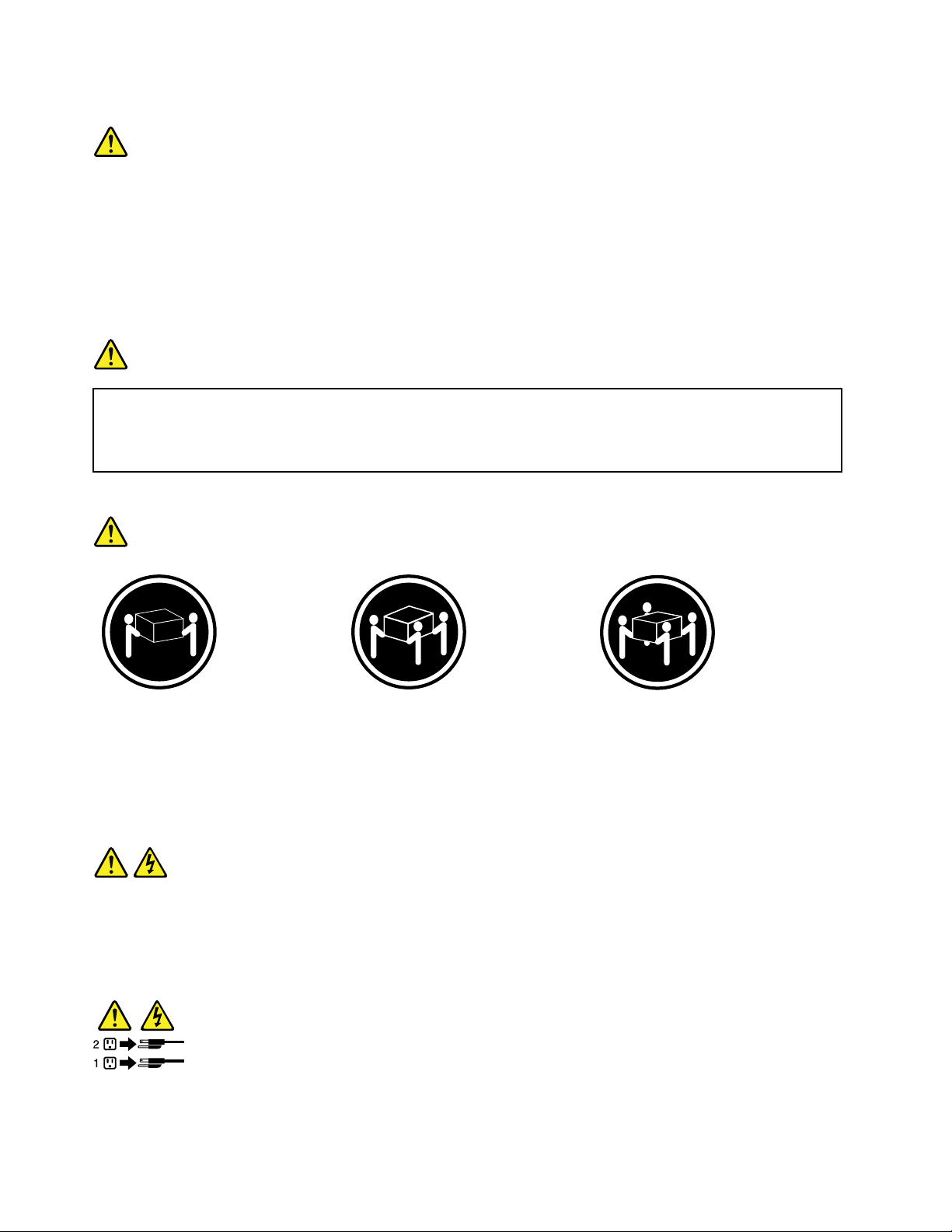
Statement4
≥18kg(39.7lb)≥32kg(70.5lb)≥55kg(121.2lb)
<32kg(70.5lb)<55kg(121.2lb)<100kg(220.5lb)
CAUTION:
Usesafepracticeswhenlifting.
Statement5
CAUTION:
Thepowercontrolbuttononthedeviceandthepowerswitchonthepowersupplydonotturnoff
theelectricalcurrentsuppliedtothedevice.Thedevicealsomighthavemorethanonepower
cord.T oremoveallelectricalcurrentfromthedevice,ensurethatallpowercordsaredisconnected
fromthepowersource.
viThinkServerRD340UserGuideandHardwareMaintenanceManual
Page 9
Statement6
CAUTION:
Ifyouinstallastrain-reliefbracketoptionovertheendofthepowercordthatisconnectedtothe
device,youmustconnecttheotherendofthepowercordtoapowersourcethatiseasilyaccessible
incaseitneedstobedisconnected.
Statement7
CAUTION:
Ifthedevicehasdoors,ensurethatyouremoveorsecurethedoorsbeforemovingorliftingthe
devicetoprotectagainstpersonalinjury.Thedoorswillnotsupporttheweightofthedevice.
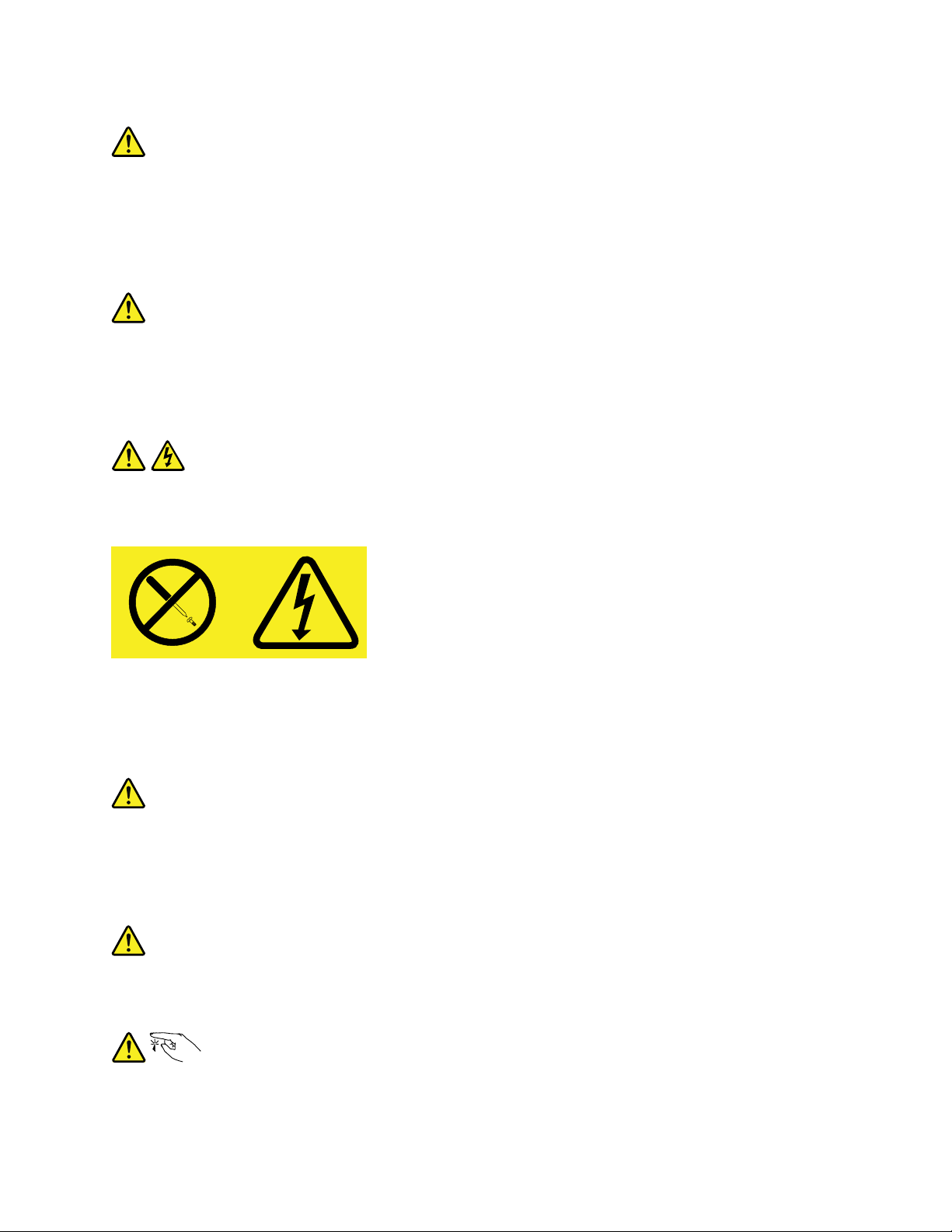
Statement8
CAUTION:
Neverremovethecoveronapowersupplyoranypartthathasthefollowinglabelattached.
Hazardousvoltage,current,andenergylevelsarepresentinsideanycomponentthathasthislabel
attached.Therearenoserviceablepartsinsidethesecomponents.Ifyoususpectaproblemwith
oneoftheseparts,contactaservicetechnician.
Statement9
CAUTION:
Disconnectthehot-swapfancablesbeforeremovingthefanfromthedevicetoprotectagainst
personalinjury.
Statement10
CAUTION:
Thefollowinglabelindicatesasharp-edgehazard.
©CopyrightLenovo2013,2014
vii
Page 10
Statement11
CAUTION:
Thefollowinglabelindicatesapotentialheathazard.
Statement12
DANGER
Overloadingabranchcircuitisapotentialfirehazardandashockhazardundercertainconditions.To
avoidthesehazards,ensurethatyoursystemelectricalrequirementsdonotexceedbranchcurrentratings
attheinstallationsite.
Statement13
CAUTION:
Ensurethattherackissecuredproperlytoavoidtippingwhentheserverunitisextendedontherails.
Statement14
CAUTION:
SomeaccessoryoroptionboardoutputsexceedClass2orlimitedpowersourcelimits.Y ou
mustinstalltheappropriateinterconnectingcablinginaccordancewithyourlocalelectricalcode
requirements.
Statement15
CAUTION:
Thepower-controlbuttononthedevicemayputthedeviceinstandbymodeinsteadofturningoff
thedevice.Inaddition,thedevicemighthavemultipleconnectionstodcpower.Toremoveall
electricalcurrentfromthedevice,ensurethatallconnectionstodcpoweraredisconnectedat
thedcpowerinputterminals.
viiiThinkServerRD340UserGuideandHardwareMaintenanceManual
Page 11
Statement16
CAUTION:
Toreducetheriskofelectricshockorenergyhazards:
•Thisequipmentmustbeinstalledbytrainedservicepersonnelinarestricted-accesslocation,as
definedbyyourlocalelectricalcodeandthelatesteditionofIEC60950.
•Connecttheequipmenttoareliablyearthedsafetyextralowvoltage(SELV)source.AnSELV
sourceisasecondarycircuitthatisdesignedsothatnormalandsinglefaultconditionsdonot
causethevoltagestoexceedasafelevel(60Vdirectcurrent).
•Thebranchcircuitovercurrentprotectionmustberatedinaccordancewithlocalelectricalcode
requirements.
•Use1.3mm
2
or16AmericanWireGauge(AWG)copperconductoronly,notexceeding3meters
inlength.
•Torquethewiring-terminalscrewsto1.4newton-metersor12inch-pounds.
•Provideareadilyavailable,approvedandrateddisconnectdeviceinthefieldwiring.
Statement17
CAUTION:
ThisproductcontainsaClass1Mlaser.Donotviewdirectlywithopticalinstruments.
Statement18
CAUTION:
Donotplaceanyobjectontopofrack-mountedproducts.
Statement19
CAUTION:
Hazardousmovingparts.Keepfingersandotherbodypartsaway.
©CopyrightLenovo2013,2014
ix
Page 12

Statement20
CAUTION:
Alithiumionbatteryisprovided.Toavoidpossibleexplosion,donotburnthebattery.Replacethe
batteryonlywiththeLenovo-approvedpart.Recycleordiscardthebatteryasinstructedbylocal
regulations.
Productsthatarenotassessed
Typicalproductsthatarenotassessedincludebutnotlimitedtothefollowing:
•ServerandIT-rackcomponents(forexample,uninterruptiblepowersuppliesandcurrentdistribution
systems)
•DevicesinITrooms(forexample,bulkstorageunitsandnetworkproducts)
•Industriallow-voltageswitchgear
xThinkServerRD340UserGuideandHardwareMaintenanceManual
Page 13

Chapter1.Generalinformation
Thischapterprovidessomegeneralinformationaboutyourproduct.
Thischaptercontainsthefollowingitems:
•“Introduction”onpage1
•“Serverdocumentation”onpage2
Introduction
ThisdocumentationforyourLenovo
specifications,componentlocations,configurationinstructions,hardwarereplacementprocedures,and
basictroubleshootinganddiagnostics.
YourservercomeswithadocumentationDVDthatcontainsvariousserverdocumentstohelpyouuseand
maintaintheserver.Meanwhile,yourservercomeswithaThinkServerEasyStartupDVDthatprovidesa
convenientsolutionforconfiguringtheserverandinstallinganoperatingsystem.
TheLenovoLimitedWarranty(LLW)containsthewarrantytermsthatapplytotheproductyoupurchasedfrom
Lenovo.ReadtheLLWonthedocumentationDVDthatcomeswithyourserver.Aprintablegenericversion
ofthelatestLLWalsoisavailableinmorethan30languagesathttp://www.lenovo.com/warranty/llw_01.If
youcannotobtaintheLLWthroughthedocumentationDVDorLenovoWebsite,contactyourlocalLenovo
officeorresellertoobtainaprintedversionoftheLLW,freeofcharge.
®
ThinkServer
®
productcontainsinformationabouttheserverfeatures,
Forwarrantyservice,consulttheworldwideLenovoSupporttelephonelist.Telephonenumbersaresubject
tochangewithoutnotice.Themostup-to-datetelephonelistforLenovoSupportisalwaysavailableonthe
Websiteathttp://www.lenovo.com/support/phone.Ifthetelephonenumberforyourcountryorregionisnot
listed,contactyourLenovoresellerorLenovomarketingrepresentative.
Toobtainthemostup-to-dateinformationabouttheserver,goto:
http://www.lenovo.com/thinkserver
LenovomaintainspagesontheWorldWideWeb,whereyoucangetthelatesttechnicalinformationand
downloaddocumentationordevicedriversandupdates.ToaccesstheLenovoSupportWebsite,goto:
http://www.lenovo.com/support
©CopyrightLenovo2013,2014
1
Page 14

Recordinformationaboutyourserverinthefollowingtable.Y ouwillneedtheinformationifyoueverneed
tohaveyourserverserviced.
Forwheretofindtheproductinformationlabelonthechassis,see“Machinetype,model,andserialnumber
label”onpage13
.
Productname
Machinetypeandmodel(MT-M)
Serialnumber(S/N)
Dateofpurchase
______________________________________________
______________________________________________
______________________________________________
______________________________________________
YoucanregisteryourserverwithLenovobyfollowingtheinstructionsat:
http://www.lenovo.com/register
Whenyouregisteryourserver,informationisenteredintoadatabase,whichenablesLenovotocontact
youincaseofarecallorothersevereproblem.AfteryouregisteryourserverwithLenovo,youwillreceive
quickerservicewhenyoucallLenovoforhelp.Inaddition,somelocationsofferextendedprivilegesand
servicestoregisteredusers.
Serverdocumentation
Thistopicprovidesgeneraldescriptionsofthevariousdocumentationforyourserverandinstructionson
howtoobtainallthedocumentation.
Printeddocuments
Thefollowingdocumentsareprintedoutandcontainedinyourserverpackage.
•ReadMeFirst
Thisisamultilingualdocumentyoushouldreadfirst.Thisdocumentguidesyoutoreadthecomplete
warranty,support,andsafetyinformationonthedocumentationDVDthatcomeswithyourserverbefore
usingtheproduct.Thisdocumentalsoprovidesinformationabouthowtofindthemostup-to-date
informationontheLenovoSupportWebsite.
•RackInstallationInstructions
Thisdocumentprovidesinstructionsonhowtoinstallyourserverintoastandardrackcabinetbyusing
therailkitshippedwiththeserver.
Note:AprintedEnglishversionofthisdocumentisincludedinyourserverpackage.PDFversionsof
otherlanguagesareprovidedonthedocumentationDVDthatcomeswiththeserver.
2ThinkServerRD340UserGuideandHardwareMaintenanceManual
Page 15

DocumentationDVD
ThedocumentationDVD,whichcomeswithyourserver,containsvariousdocumentsforyourserverin
PortableDocumentFormat(PDF)andHyperTextMarkupLanguage(HTML).ThedocumentationDVDisnot
bootable.ToviewthedocumentsontheDVD,youwillneedacomputerwithaWebbrowserandtheAdobe
Readerprogram,whichisavailablefordownloadat:
http://www.adobe.com
TostartthedocumentationDVD,inserttheDVDintotheopticaldrive.TheDVDisAutoPlayenabledand
startsautomaticallyinmostMicrosoft
®
Linux
operatingsystem,openthelaunch.htmfilelocatedintherootdirectoryoftheDVD.
®
Windows
®
environments.IftheDVDfailstostartorifyouareusinga
Note:LenovomaintainspagesontheWorldWideWeb,whereyoucangetthelatesttechnicalinformation
anddownloaddocumentationordevicedriversandupdates.Someinformationinthedocumentsonthe
documentationDVDmightchangewithoutnoticeafterthefirstreleaseoftheDVD.Y oucanalwaysobtainall
themostup-to-datedocumentationforyourserverfromtheLenovoWebsiteat:
http://www.lenovo.com/UserManuals
ThefollowingdocumentsareonthedocumentationDVDthatcomeswithyourserver:
•Safety,Warranty,andSupportInformation
Thisisamultilingualdocumentthatincludesallthesafetystatementsforyourproductinmorethan30
languages.Besuretoreadandunderstandallthesafetystatementsbeforeusingtheproduct.This
documentalsoincludestheLenovowarrantystatement,CustomerReplaceableUnits(CRUs)information,
andinformationabouthowtocontacttheLenovoCustomerSupportCenter.
•LenovoLicenseAgreement
ThisdocumentincludesthetermsandconditionsoftheLenovoLicenseAgreement.
•UserGuideandHardwareMaintenanceManual
Thisdocumentprovidesdetailedinformationtohelpyougetfamiliarwithyourserverandhelpyou
use,configure,andmaintainyourserver.Someinformationinthisdocument,ifspecified,isintended
forservicetechniciansonly.
•RackInstallationInstructions
Thisdocumentprovidesinstructionsonhowtoinstallyourserverintoastandardrackcabinetbyusing
therailkitshippedwiththeserver.
•ThinkServerManagementModuleUserGuide
Thisdocumentprovidesinformationaboutserverremotemanagement.ThisdocumentisinEnglishonly.
YoumightfindthisdocumentonthedocumentationDVDthatcomeswithyourserver.Ifnot,downloadit
fromtheLenovoWebsiteat:
http://www.lenovo.com/UserManuals
Note:Toobtainadvancedremotemanagementfunctions,installaThinkServerManagementModule
Premium(TMMPremium)ontheTMMPremiumconnectoronthesystemboard.See“Installingor
removingtheThinkServerManagementModulePremium”onpage105
.
•MegaRAIDSASSoftwareUserGuide
ThisdocumentprovidesinformationaboutRedundantArrayofIndependentDisks(RAID)andhowto
usetheutilityprogramstoconfigure,monitor,andmaintainyourserverRAIDandrelateddevices.This
documentisinEnglishonly.
Note:RefertothisdocumentforhardwareRAIDinformationifyouhavearequiredRAIDcardinstalledin
theserver.See“InstallingorremovingtheRAIDcard”onpage90
.ForinformationabouttheThinkServer
RAID300(alsoknownastheonboardSASsoftwareRAID),see“ConfiguringtheThinkServerRAID
300”onpage64.
Chapter1.Generalinformation3
Page 16

Supplementarydocuments
Dependingonyourserver,yourdocumentationDVDmightcontainsupplementarydocumentsprovidedby
Lenovo,includingdocumentsforEthernetcards,hostbusadapters(HBAs),orotheroptionalparts.
4ThinkServerRD340UserGuideandHardwareMaintenanceManual
Page 17

Chapter2.Serversetuproadmap
Thischapterprovidesageneralroadmaptoguideyouthroughsettingupyourserver.
Theserversetupprocedurevariesdependingontheconfigurationoftheserverwhenitwasdelivered.In
somecases,theserverisfullyconfiguredandyouneedtoconnecttheservertothenetworkandanacpower
source,andthenyoucanturnontheserver.Inothercases,theserverneedstohavehardwarefeatures
installed,requireshardwareandfirmwareconfiguration,andrequiresanoperatingsystemtobeinstalled.
Thegeneralprocedureforsettingupyourserveris:
1.Unpacktheserverpackage.See“Serverpackage”onpage7.
2.Installanyrequiredhardwareorserveroption.SeetherelatedtopicsinChapter6“Installing,removing,
orreplacinghardware”onpage73.
3.Installyourserverintoastandardrackcabinetbyusingtherailkitshippedwiththeserver.SeeRack
InstallationInstructionsthatcomeswithyourserver.
4.ConnecttheEthernetcableandpowercordstotheserver.See“Rearviewoftheserver”onpage
23tolocatetheconnectors.
5.Turnontheservertoverifyoperation.See“Turningontheserver”onpage49.
6.ReviewtheUnifiedExtensibleFirmwareInterface(UEFI)settingsandcustomizeasneeded.See“Using
theSetupUtilityprogram”onpage51.
7.ConfigureRAIDandinstalltheoperatingsystemandbasicdrivers.See“UsingtheThinkServer
EasyStartupprogram”onpage59and“ConfiguringRAID”onpage62.
8.Installanyadditionaldriversneededforaddedfeatures.Refertotheinstructionsthatcomewiththe
hardwareoption.
9.ConfigureEthernetsettingsintheoperatingsystembyreferringtotheoperatingsystemhelp.Thisstep
isnotrequirediftheoperatingsystemwasinstalledusingtheThinkServerEasyStartupprogram.
10.Checkforfirmwareanddriverupdates.See“Updatingthefirmware”onpage71.
11.Installotherapplications.Refertothedocumentationthatcomeswiththeapplicationsthatyouwantto
install.
©CopyrightLenovo2013,2014
5
Page 18

6ThinkServerRD340UserGuideandHardwareMaintenanceManual
Page 19
Chapter3.Productoverview
ID
CPU
Mem
PSU
Thischapterprovidesinformationabouttheserverpackage,features,specifications,softwareprograms,
andcomponentlocations.
Thischaptercontainsthefollowingitems:
•“Serverpackage”onpage7
•“Features”onpage7
•“Specifications”onpage11
•“Software”onpage11
•“Locations”onpage13
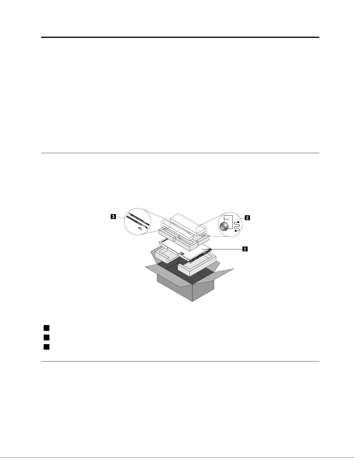
Serverpackage
Theserverpackageincludestheserver,arailkit,powercords,printeddocumentation,adocumentation
DVD,andsoftwaremedia.
Note:Dependingonthemodel,yourservermightlookslightlydifferentfromtheillustrationinthistopic.
Figure1.Serverpackage
1Server
2Materialbox(includingpowercords,printeddocumentation,adocumentationDVD,andsoftwaremedia)
3Railkit
Features
Thistopicprovidesgeneralinformationabouttheserverfeaturesforvariousmodels.Dependingonyour
specificmodel,somefeaturesmightvaryornotbeavailable.Forinformationaboutyourspecificmodel,use
theSetupUtilityprogram.See“ViewinginformationintheSetupUtilityprogram”onpage51.Youalsocan
refertothePersonalSystemsReferencedocumentforThinkServerproductsat:
http://www.lenovo.com/psref/
©CopyrightLenovo2013,2014
7
Page 20

Microprocessor
OneortwoIntel
®
®
Xeon
microprocessors(internalcachesizevariesbymodel)
ForalistofThinkServermicroprocessoroptions,goto:
http://www.lenovo.com/thinkserver
Memory
Yourserverhas12memoryslots.Formoreinformation,see“Memorymoduleinstallationrules”onpage81
Powersupply
Oneortwo550-watthot-swapredundantpowersupplies(Universalinputandcompliantwith80PLUSGold)
Systemfans
Yourservercomeswithsixsystemfanstoprovidepropersystemcoolingandairflow.
Internaldrives
Internaldrivesaredevicesthatyourserverusestoreadandstoredata.Theinternaldrivessupported
byyourservervarybymodel.
•Harddiskdrive
–Uptofour3.5-inchhot-swapSerialAdvancedTechnologyAttachment(SATA)orSerialAttached
SCSI(SAS)harddiskdrives(SCSIistheacronymforSmallComputerSystemInterface)orSATA
solid-statedrives
–Uptosix2.5-inchhot-swapSATAorSASharddiskdrivesorSATAsolid-statedrives(forservermodels
withaslimopticaldrive)
–Uptoeight2.5-inchhot-swapSATAorSASharddiskdrivesorSATAsolid-statedrives(forserver
modelswithoutaslimopticaldrive)
–SupportPCIExpresssolid-statedrives
Thefollowingservermodelsalsoareavailable:
.
–Servermodelswithoutharddiskdrivesorsolid-statedrives
–Servermodelswithoutharddiskdrives,solid-statedrives,backplanes,RAIDcards,andrelatedcables
Note:Theterm“2.5-inchhot-swapharddiskdrives”or“2.5-inchharddiskdrives”hereinafterreferstoall
thesupportedtypesof2.5-inchharddiskdrives,includingsolid-statedrives.
•Opticaldrive
–OneslimSATAopticaldriveinsomemodels
Forthelocationinformationabouttheinternaldrivesordrivebays,see“Servercomponents”onpage25
Externaldrives
Yourserversupportsexternaltapedrivesthatenableyoutostoredataontapes.Toinstallanexternaltape
drive,see“Installinganexternaltapedrive”onpage144.
8ThinkServerRD340UserGuideandHardwareMaintenanceManual
.
Page 21

Expansionslots
•Tworisercardassemblyslotsonthesystemboard
•OnePCIExpresscardslotontherisercardassembly1
•OnePCIExpresscardslotontherisercardassembly2
Fordetailedinformation,see“Rearviewoftheserver”onpage23.
Input/Output(I/O)features
•OneortwoVideoGraphicsArray(VGA)DB-15connectors
•Oneserialconnectorontherearpanel
•SixUSB2.0connectors(twoonthefrontpanelandfourontherearpanel)
•ThreeRJ-45Ethernetconnectorsontherearpanel(Ethernetconnector0isforsystemmanagement)
Forthelocationinformationabouttheconnectors,refertotherelatedtopicsin“Locations”onpage13
.
Videosubsystem
AnintegratedgraphicscontrollerintheThinkServerManagementModule(TMM),whichalsoisknown
astheBaseboardManagementController(BMC)chip,onthesystemboardtosupportVGAconnectors
forconnectingvideodevices
Ethernetconnectivity
TherearethreeRJ-45Ethernetconnectorsontherearpanelwith10megabitspersecond(Mbps),100
Mbps,or1000Mbpsnetworkconnectivity.TheEthernetconnector0isforsystemmanagementbydefault.
However,youalsocansettheEthernetconnector1or2forsystemmanagementuseintheSetupUtility
program.See“SettingthemodeoftheEthernetconnectors”onpage57
.
Formoreinformation,see“Rearviewoftheserver”onpage23.
Reliability,availability,andserviceability
Reliability,availability,andserviceability(hereinafterreferredtoasRAS)arethreeimportantserverdesign
features.TheRASfeatureshelpyoutoensuretheintegrityofthedatastoredontheserver,theavailabilityof
theserverwhenyouneedit,andtheeasewithwhichyoucandiagnoseandcorrectproblems.
YourserverhasthefollowingRASfeatures:
•Securityfeatures
–Administratorpasswordanduserpasswordtohelpprotectunauthorizedaccesstotheserver(see
“Usingpasswords”onpage55)
–ThinkServerT rustedPlatformModule(TPM),whichisasecuritychip,tohelpenhanceserversecurity
Note:TheTPMisonlyavailableinsomemodels.
–Remotemonitoringorcontrolbyanadministratortoprovideprotectionorhelp
–Hot-swapredundantpowersuppliestohelpavoidsignificantinterruptiontotheoperationofthe
systemwhenapowersupplyfails
•Basicsystemmanagementfeatures
–Abilitytostorethepower-onself-test(POST)hardwaretestresults
–BIOSSetupUtilityprogram
Chapter3.Productoverview9
Page 22

TheBIOSSetupUtilityprogramhelpsyouviewtheserverinformationandconfiguretheserverinthe
pre-operatingsystemenvironment.See“UsingtheSetupUtilityprogram”onpage51
.
–TMM(alsoknownasBMC)andIntelligentPlatformManagementInterface(IPMI)2.0
ThesystemboardplatformmanagementsubsystemisbasedontheintegratedTMMfeatures.The
TMMisamanagementchipthatisintegratedonthesystemboardofyourserver.WiththeTMM
chip,nomatterwhatconditiontheserveroperatingsystemisinandnomatteriftheserverisonor
off,aslongastheserverisconnectedtonetworkandanacpowersource,theinteractionwiththe
TMM-controlledserverscanbeachievedthroughsystemnetwork.Theusercanobtaintheserver
hardwarehealthinformationandsystemeventlog(SEL),andisabletoconducttheoperations
includingturningonorofftheserver,restartingtheserver,andsoon.Thispartofservermanagement
isindependentoftheoperatingsystemandiscalledout-of-bandmanagement.
ThesystemboardplatformmanagementsubsystemconsistsoftheintegratedTMM,communication
buses,sensors,theBIOS,andservermanagementfirmware.Itisresponsibleforerrorreporting,
systempowercontrol,thermalmonitoring,systemfancontrol,andothermanagementfeatures.The
TMMprovidessystemmanagementandmonitoringfeaturesbasedontheIPMI2.0specification.IPMI
helpslowertheoverallcostsofservermanagement.YoucanfindmoreinformationaboutIPMI2.0
fromtheWebsiteofIntel.TheTMMalsosupportssomenon-IPMIfeatures,suchastheDynamicHost
ConfigurationProtocol(DHCP)andthePlatformEnvironmentControlInterface(PECI),toprovide
moresystemmanagementfunctions.
Youcanfindthedefaultusername,password,andotherinformationfortheTMMintheThinkServer
ManagementModuleUserGuide,whichisavailablefordownloadat:
http://www.lenovo.com/UserManuals
–Hot-swapfeature
Yourserversupportshot-swapharddiskdrivesandhot-swapredundantpowersupplies.Withthe
hot-swapfeature,youcaninstall,remove,orreplaceahot-swapdevicewithoutturningofftheserver.
–PrebootExecutionEnvironment(PXE)
TheIntelPXEtechnologyenablesyoutostartyourcomputers,loadanoperatingsystem,ordeploy
executableimagesfromaremoteserverbyusinganetworkinterface.Theoperationcanbedone
independentlyoflocaldatastoragedevices(suchasharddiskdrives)oroperatingsystems.
–RedundantArrayofIndependentDisks(RAID)
YourserversupportsonboardSATAsoftwareRAID.IfarequiredRAIDcardisinstalled,yourserver
alsosupportsadvancedSATA/SAShardwareRAIDconfigurations.Fordetailedinformation,see
“ConfiguringRAID”onpage62
.
–Statuslight-emittingdiodes(LEDs)anddiagnosticLEDs
FormoreinformationabouttheLEDsforyourserver,refertotherelatedtopicsin“Locations”on
page13.
–Softwareprograms
Formoreinformationaboutthesoftwareprograms,see“Software”onpage11.
–WakeonLAN
WhentheWakeonLANfeatureisenabledonacomputerthatisconnectedtoaLAN,anetwork
administratorcanremotelyturnonorwakeupthecomputerfromamanagementconsoleusingremote
networkmanagementsoftware.Besides,manyotherfunctions,suchasdatatransferandsoftware
updates,canbeperformedremotelywithoutremoteattendanceandcanbedoneafternormalworking
hoursandonweekendstosavetimeandincreaseproductivity.
•Advancedsystemmanagementfeatures
TheadvancedsystemmanagementfeaturesareonlyavailablewhentheTMMdetectsthepresenceofa
ThinkServerManagementModulePremium(TMMPremium),whichalsoisknownasintegratedkeyboard,
video,andmouse(iKVM)key.TheTMMPremiumisaremotemanagementmodule.Y oucanpurchase
aTMMPremiumfromLenovoandinstallitontheTMMPremiumconnector(alsoknownasiKVM
10ThinkServerRD340UserGuideandHardwareMaintenanceManual
Page 23

connector)onthesystemboardofyourservertoenabletheiKVMfunctionandactivatetheadvanced
systemmanagementfeatures.
Formoreinformationaboutadvancedsystemmanagement,refertotheThinkServerManagementModule
UserGuide,whichisavailablefordownloadat:
http://www.lenovo.com/UserManuals
Specifications
Thistopicliststhephysicalspecificationsforyourserver.
Dimensions
Width:436mm(17.17inches)withouthandles;482.4mm(18.99inches)withhandles
Height:43.6mm(1.72inches)
Depth:720.6mm(28.37inches)withouthandles;734mm(28.90inches)withhandles
Weight
Theproductweightvariesdependingondifferentsystemconfigurations.
Rangeofproductweightwithoutpackage:12kg(26.46lb)to17kg(37.48lb)
Rangeofproductweightwithpackage:15kg(33.07lb)to24kg(52.91lb)
Environment
•Airtemperature:
Operating:10°Cto35°C(50°Fto95°F)
Storage:-40°Cto70°C(-40°Fto158°F)inoriginalshippingpackage
•Altitude:0to3048m(0to10000ft)inanunpressurizedenvironment
•Humidity:
Operating:8%to80%(non-condensing)
Storagewithoutpackage:8%to80%(non-condensing)
Storagewithpackage:8%to90%(non-condensing)
Electricalinput
•Universalinput:
–Lowrange:
Minimum:100Vac
Maximum:127Vac
Inputfrequencyrange:50to60Hz
–Highrange:
Minimum:200Vac
Maximum:240Vac
Inputfrequencyrange:50to60Hz
Software
Thistopicprovidesinformationaboutthesoftwareprogramsthatyoucanusetosetup,use,andmaintain
theserver.
Chapter3.Productoverview11
Page 24

ThinkServerEasyStartup
TheThinkServerEasyStartupprogramsimplifiestheprocessofconfiguringRAIDandinstallingsupported
MicrosoftWindowsandLinuxoperatingsystemsanddevicedriversonyourserver.Thisprogramisprovided
withyourserveronaself-starting(bootable)ThinkServerEasyStartupDVD.Theuserguidefortheprogram
alsoisontheDVDandcanbeaccesseddirectlyfromtheprograminterface.Fordetailedinformation,see
“UsingtheThinkServerEasyStartupprogram”onpage59
.
ThinkServerEasyUpdateFirmwareUpdater
TheThinkServerEasyUpdateFirmwareUpdaterprogram(hereinafterreferredtoastheFirmwareUpdater
program)enablesyoutomaintainyourserverfirmwareup-to-dateandhelpsyouavoidunnecessaryserver
outages.TheFirmwareUpdaterprogramisprovidedontheLenovoSupportWebsite.Formoreinformation
aboutdownloadingandusingtheFirmwareUpdaterprogram,see“Updatingthefirmware”onpage71
LenovoThinkServerEasyManage
TheLenovoThinkServerEasyManageprogramenablesenterpriseuserstoremotelycontrolandmonitor
multipleLenovoserverswithinaLAN.
Fordetailedinformation,see“UsingtheLenovoThinkServerEasyManageprogram”onpage71.
BIOSandTMMupdateutilities
TheBIOSandTMM(alsoknownasBMC)firmwarekeepsupdatingaftertheshipmentoftheserver.
LenovomaintainspagesontheSupportWebsiteandprovidestheBIOSandTMMupdateutilitieswith
instructionsfordownloadtohelpyouupdatetheBIOSandTMMfirmwareifneeded.Formoreinformation,
see“UpdatingorrecoveringtheBIOS”onpage58
and“Updatingthefirmware”onpage71.
.
RAIDconfigurationutilities
YourserversupportsonboardSATAsoftwareRAID.IfarequiredRAIDcardisinstalled,yourserveralso
supportsadvancedSATA/SAShardwareRAIDconfigurations.Fordetailedinformation,see“Configuring
RAID”onpage62.
Remotemanagementsoftware
TheintegratedTMMprovidesbasicremotemanagementfeaturesfortheserver.Theadd-onTMMPremium
optionprovidesadvancedremotemanagementfeaturesfortheserver.
Fordetailedinformationabouttheremotemanagementsoftwareandserverremotemanagement,referto
theThinkServerManagementModuleUserGuide,whichisavailablefordownloadat:
http://www.lenovo.com/UserManuals
ThinkServerSmartGridT echnology
TheThinkServerSmartGridTechnologyprogramhelpsadministratorstomonitorandmanageserver
performance,especiallythepowerconsumptionforgroupsofserversequippedwiththeIntelIntelligent
PowerNodeManagertechnology.
LenovoprovidesatrialversionoftheThinkServerSmartGridTechnologyprogramwithafree90-day
subscription.After90days,youmustrenewthelicensetocontinueusingtheprogram.Y oucanpurchase
thelicensefromLenovotoactivatetheThinkServerSmartGridTechnologyprogramandexpandthe
managementcapabilityoftheprogramwhenthefreetrialends.
12ThinkServerRD340UserGuideandHardwareMaintenanceManual
Page 25

TodownloadtheThinkServerSmartGridTechnologyprogram,gotohttp://www.lenovo.com/driversand
followtheinstructionsontheWebpage.
FordetailedinformationaboutusingtheThinkServerSmartGridTechnologyprogram,refertothehelp
systemfortheprogram.
Diagnosticprograms
Thefollowingdiagnosticprogramsareavailableforyoutodiagnoseserverproblems:
•ThinkServerDiagnosticTool
•ThinkServerSystemProfileCollectionT ool
Formoreinformation,see“Usingadiagnosticprogram”onpage178
.
Locations
Thistopicprovidesinformationtohelpyoulocateyourservercomponents.
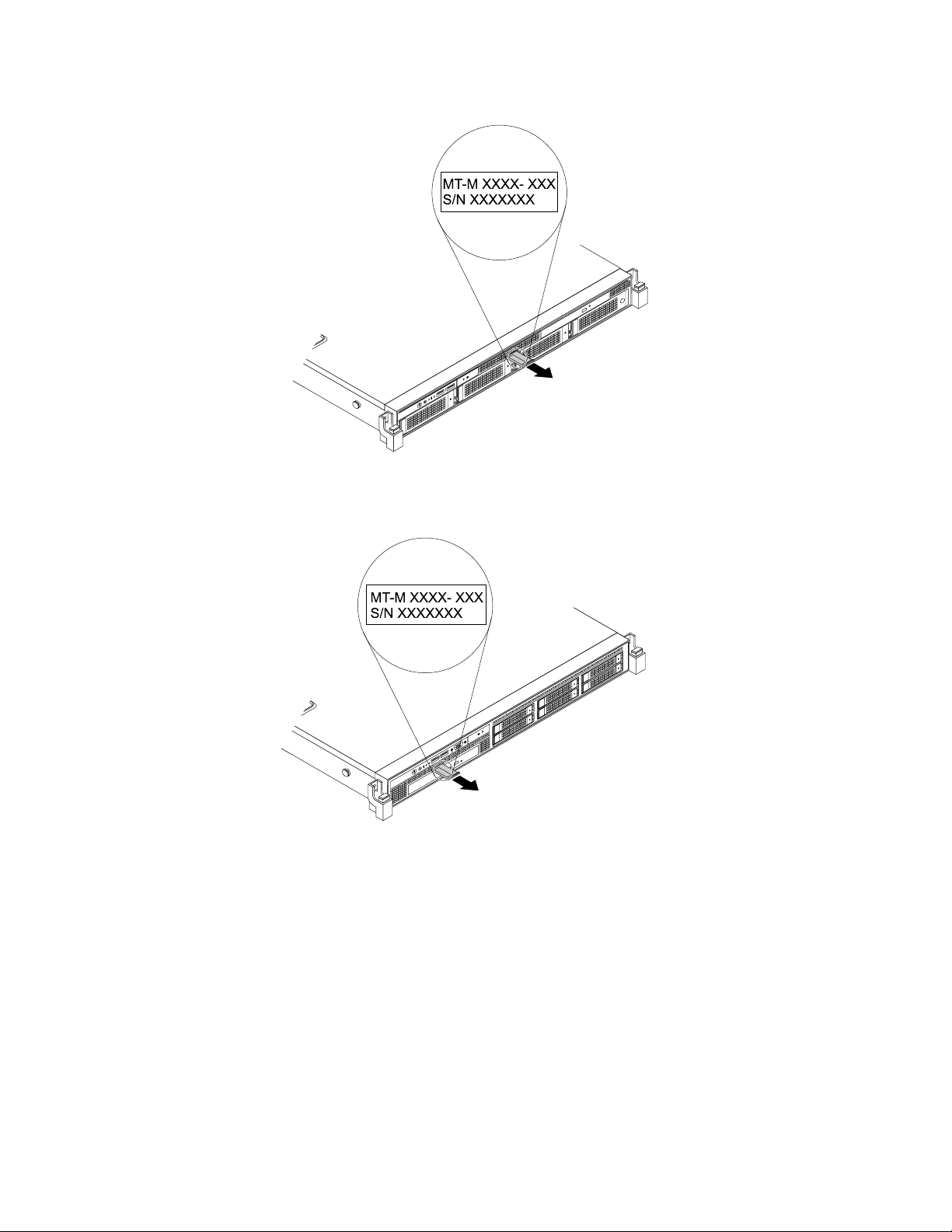
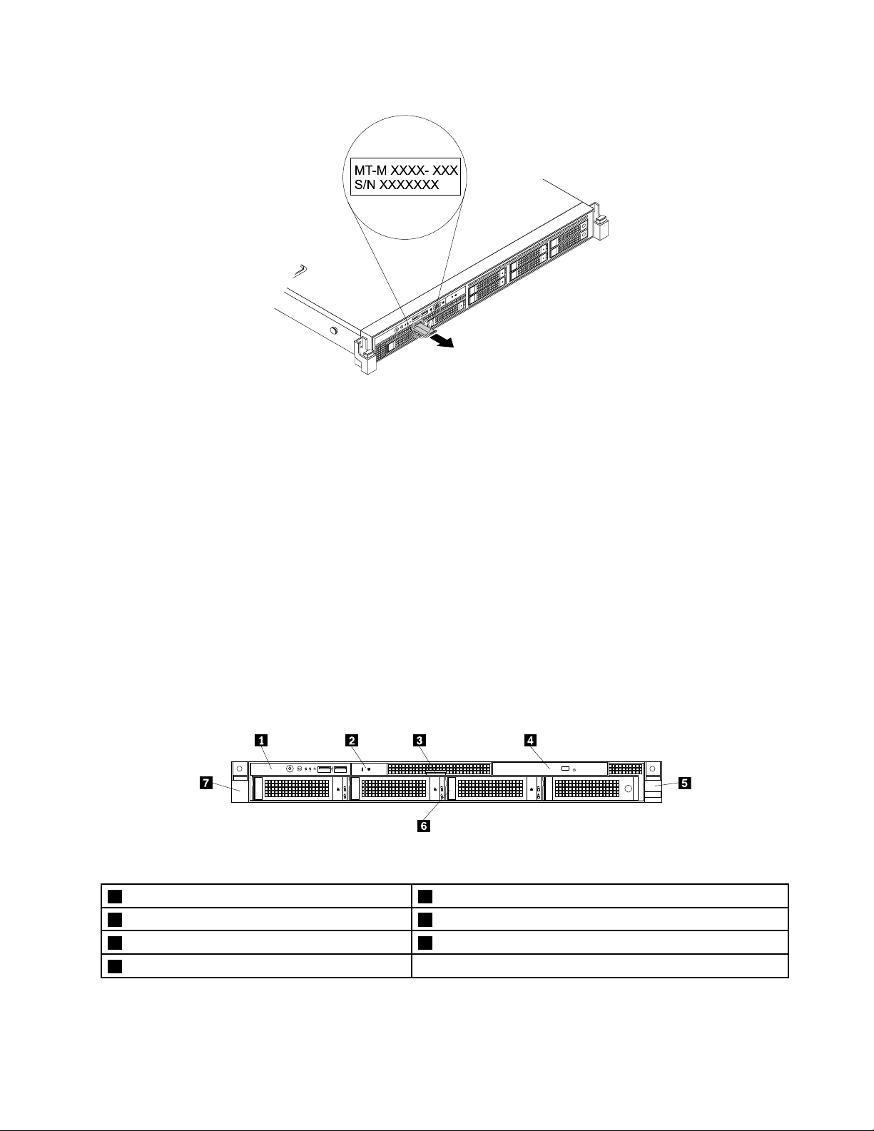
Machinetype,model,andserialnumberlabel
Thistopichelpsyoulocatethelabelthatcontainsthemachinetype,model,andserialnumberinformation
foryourserver.
WhenyoucontactLenovoforhelp,themachinetype,model,andserialnumberinformationhelpssupport
technicianstoidentifyyourserverandprovidefasterservice.
Theillustrationsinthistopicshowthemachinetype,model,andserialnumberlabelsonservermodelswith
differenthard-disk-driveconfigurations.Dependingonthemodel,yourservermightlookslightlydifferent
fromtheillustrationsinthistopic.
Themachinetype,model,andserialnumberlabelisattachedonthepull-outinformationcardinthe
followingservermodels:
•Servermodelswithfour3.5-inchhard-disk-drivebays
•Servermodelswithsix2.5-inchhard-disk-drivebays
•Servermodelswitheight2.5-inchhard-disk-drivebays
Thepull-outinformationcardisasmallplastictabandcanbeslidoutofthefrontofthechassis.
Chapter3.Productoverview13
Page 26
ID
CPU
Mem
PSU
MT-M XXXX- XXX
S/N XXXXXXX
Figure2.Labelonservermodelswithfour3.5-inchhard-disk-drivebays
PSU
Mem
CPU
ID
MT-M XXXX- XXX
S/N XXXXXXX
Figure3.Labelonservermodelswithsix2.5-inchhard-disk-drivebays
14ThinkServerRD340UserGuideandHardwareMaintenanceManual
Page 27
CPU
Mem
PSU
ID
MT-M XXXX- XXX
S/N XXXXXXX
Figure4.Labelonservermodelswitheight2.5-inchhard-disk-drivebays
CPU
MemPSU
ID
Frontviewoftheserver
Thistopicprovidesinformationtohelpyoulocatethepartsonthefrontoftheserver.
Thefrontviewoftheservervariesbymodel.Theillustrationsinthistopicshowtheserverfrontviews
basedonthesupportedharddiskdrives:
•“Frontviewofservermodelswithfour3.5-inchhard-disk-drivebays”onpage15
•“Frontviewofservermodelswithsix2.5-inchhard-disk-drivebays”onpage16
•“Frontviewofservermodelswitheight2.5-inchhard-disk-drivebays”onpage18
Note:Dependingonthemodel,yourservermightlookslightlydifferentfromtheillustrationsinthistopic.
Frontviewofservermodelswithfour3.5-inchhard-disk-drivebays
Thefollowingillustrationshowsthefrontviewofservermodelswithfour3.5-inchhard-disk-drivebays.
Figure5.Frontviewofservermodelswithfour3.5-inchhard-disk-drivebays
1Frontpanel5Rightrackhandle
2IntelligentDiagnosticsModule63.5-inchhard-disk-drivearea
3Pull-outinformationcard7Leftrackhandle
4Slimopticaldrive(availableinsomemodels)
Chapter3.Productoverview15
Page 28
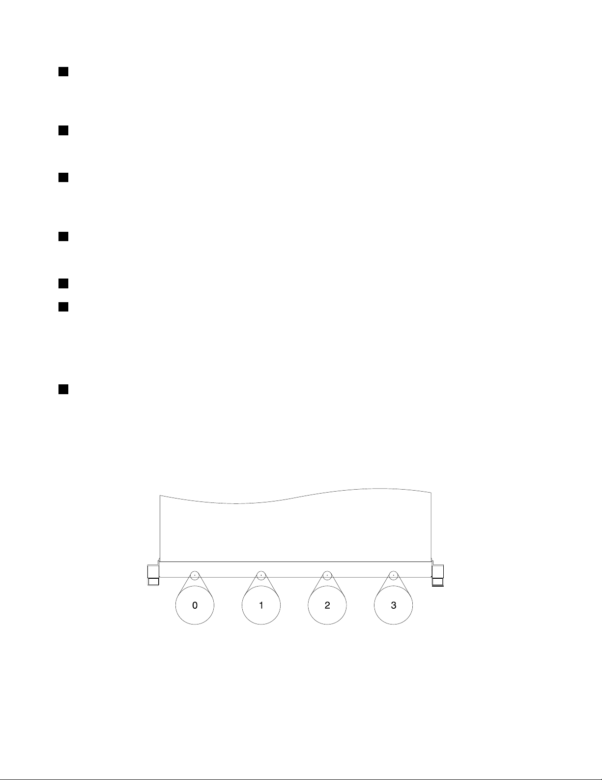
1Frontpanel
Fordetailedinformationaboutthecontrols,connectors,andstatusLEDsonthefrontpanel,see“Front
panel”onpage19.
2IntelligentDiagnosticsModule
Formoreinformation,see“IntelligentDiagnosticsModule”onpage22.
3Pull-outinformationcard
Themachinetype,model,andserialnumberlabeloftheserverisattachedonthepull-outinformationcard.
See“Machinetype,model,andserialnumberlabel”onpage13.
4Slimopticaldrive
SomeservermodelscomewithaslimSATAopticaldrive.
5Rightrackhandle
7Leftrackhandle
Ifyourserverisinstalledinarackcabinet,youcanusetherackhandlestoslidetheserveroutoftherack
cabinet;orusetherackhandlesandscrewstosecuretheserverintherackcabinetsothattheserver
cannotslideout,especiallyinvibration-proneareas.Formoreinformation,refertotheRackInstallation
Instructionsthatcomeswithyourserver.
63.5-inchhard-disk-drivearea
TheEMIintegrityandcoolingoftheserverareprotectedbyhavingalldrivebayscoveredoroccupied.
Thenumberoftheinstalledharddiskdrivesinyourservervariesbymodel.Thevacanthard-disk-drive
baysareoccupiedbydummyhard-disk-drivetrays.
Thehard-disk-drivebaynumbersaremarkedonthetopedgeofthefrontbezel.
Figure6.3.5-inchhard-disk-drivebaynumbers(topviewoftheserver)
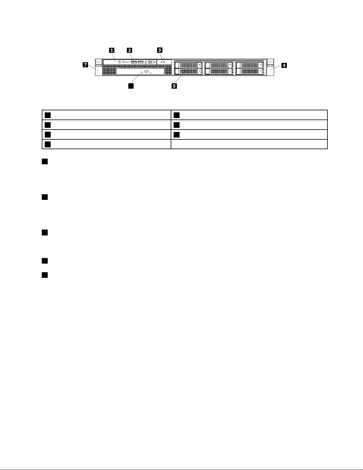
Frontviewofservermodelswithsix2.5-inchhard-disk-drivebays
Thefollowingillustrationshowsthefrontviewofservermodelswith2.5-inchhard-disk-drivebays.
16ThinkServerRD340UserGuideandHardwareMaintenanceManual
Page 29
ID
6
CPU
MemPSU
Figure7.Frontviewofservermodelswithsix2.5-inchhard-disk-drivebays
1Frontpanel52.5-inchhard-disk-drivearea
2Pull-outinformationcard
3IntelligentDiagnosticsModule
4Rightrackhandle
1Frontpanel
6Slimopticaldrive(availableinsomemodels)
7Leftrackhandle
Fordetailedinformationaboutthecontrols,connectors,andstatusLEDsonthefrontpanel,see“Front
panel”onpage19.
2Pull-outinformationcard
Themachinetype,model,andserialnumberlabeloftheserverisattachedonthepull-outinformationcard.
See“Machinetype,model,andserialnumberlabel”onpage13.
3IntelligentDiagnosticsModule
Formoreinformation,see“IntelligentDiagnosticsModule”onpage22
4Rightrackhandle
7Leftrackhandle
.
Ifyourserverisinstalledinarackcabinet,youcanusetherackhandlestoslidetheserveroutoftherack
cabinet;orusetherackhandlesandscrewstosecuretheserverintherackcabinetsothattheserver
cannotslideout,especiallyinvibration-proneareas.Formoreinformation,refertotheRackInstallation
Instructionsthatcomeswithyourserver.
Chapter3.Productoverview17
Page 30
52.5-inchhard-disk-drivearea
4
5
0
1
2
3
0
1
2
3
4
5
CPU
MemPSU
ID
6
TheEMIintegrityandcoolingoftheserverareprotectedbyhavingalldrivebayscoveredoroccupied.
Thenumberoftheinstalledharddiskdrivesinyourservervariesbymodel.Thevacanthard-disk-drive
baysareoccupiedbydummyhard-disk-drivetrays.
Thehard-disk-drivebaynumbersaremarkedonthetopedgeofthefrontbezel.
Figure8.2.5-inchhard-disk-drivebaynumbers(topviewoftheserver)
6Slimopticaldrive
SomeservermodelscomewithaslimSATAopticaldrive.
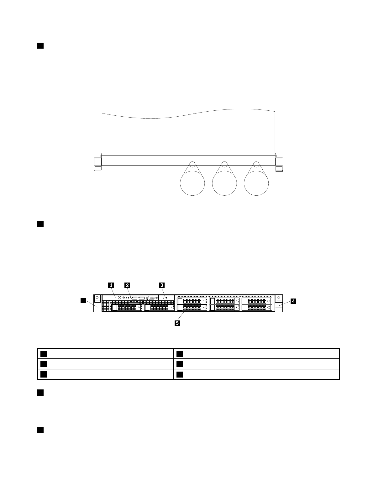
Frontviewofservermodelswitheight2.5-inchhard-disk-drivebays
Thefollowingillustrationshowsthefrontviewofservermodelswitheight2.5-inchhard-disk-drivebays.
Figure9.Frontviewofservermodelswitheight2.5-inchhard-disk-drivebays
1Frontpanel4Rightrackhandle
2Pull-outinformationcard
3IntelligentDiagnosticsModule
1Frontpanel
Fordetailedinformationaboutthecontrols,connectors,andstatusLEDsonthefrontpanel,see“Front
panel”onpage19
.
52.5-inchhard-disk-drivearea
6Leftrackhandle
2Pull-outinformationcard
Themachinetype,model,andserialnumberlabeloftheserverisattachedonthepull-outinformationcard.
See“Machinetype,model,andserialnumberlabel”onpage13
18ThinkServerRD340UserGuideandHardwareMaintenanceManual
.
Page 31

3IntelligentDiagnosticsModule
0
6
7
2
3
4
5
0
2
3
4
5
6
7
1
1
Formoreinformation,see“IntelligentDiagnosticsModule”onpage22.
4Rightrackhandle
6Leftrackhandle
Ifyourserverisinstalledinarackcabinet,youcanusetherackhandlestoslidetheserveroutoftherack
cabinet;orusetherackhandlesandscrewstosecuretheserverintherackcabinetsothattheserver
cannotslideout,especiallyinvibration-proneareas.Formoreinformation,refertotheRackInstallation
Instructionsthatcomeswithyourserver.
52.5-inchhard-disk-drivearea
TheEMIintegrityandcoolingoftheserverareprotectedbyhavingalldrivebayscoveredoroccupied.
Thenumberoftheinstalledharddiskdrivesinyourservervariesbymodel.Thevacanthard-disk-drive
baysareoccupiedbydummyhard-disk-drivetrays.
Thehard-disk-drivebaynumbersaremarkedonthetopedgeofthefrontbezel.
Figure10.2.5-inchhard-disk-drivebaynumbers(topviewoftheserver)
Frontpanel
Thistopicprovidesinformationtohelpyoulocatethecontrols,connectors,andLEDsonthefrontpanelof
theserver.
Chapter3.Productoverview19
Page 32

Thefollowingillustrationshowsthecontrols,connectors,andLEDsonthefrontpaneloftheserver.
ID
Figure11.Frontpanel
1PowerbuttonwithpowerstatusLED
2IDbuttonwithIDLED
3NetworkInterfaceController(NIC)1statusLED7FrontUSBconnector2
4NIC2statusLED8FrontVGADB-15connector
5SystemerrorLED
6FrontUSBconnector1
Note:ThefrontVGADB-15connectorisonlyavailableinservermodelswith2.5-inchharddiskdrives.
1PowerbuttonwithpowerstatusLED
Youcanpressthepowerbuttontoturnontheserverwhenyoufinishsettinguptheserver.Youalsocan
holdthepowerbuttonforseveralsecondstoturnofftheserverifyoucannotturnofftheserverfromthe
operatingsystem.SeeChapter4“Turningonandturningofftheserver”onpage49.ThepowerstatusLED
helpsyoutodeterminethecurrentpowerstatus.
PowerstatusLED
OnGreen
Off
Blinking
Color
Theserverison.
None
GreenTheserverisinACPIS1mode,whichalsoisknown
Theserverisoff.
asPowerOnSuspend(POS)mode.Inthismode,the
microprocessorisnotworkingwhileotherhardware
devicesarestillworking.
Description
2IDbuttonwithIDLED
WhenyoupresstheIDbutton,theIDLEDsonboththefrontandrearoftheserverarelittohelpyoulocate
theserveramongotherservers.YoualsocanturnontheIDLEDsusingaremotemanagementprogram
forserverpresencedetection.
IDLED
On
Off
20ThinkServerRD340UserGuideandHardwareMaintenanceManual
Color
None
Blue
Theserverisidentified.
TheIDLEDisnotinuseortheserverisnotidentified.
Description
Page 33

3NIC1statusLED
4NIC2statusLED
ThetwoNICstatusLEDsindicatetheLANstatusfortheEthernetconnector1andEthernetconnector2
ontherearpaneloftheserver.
Description
5SystemerrorLED
NICstatusLEDColor
OnGreen
Off
Blinking
TheserverisconnectedtoaLAN.
None
Green
TheserverisdisconnectedfromaLAN.
TheLANisconnectedandactive.
ThesystemerrorLEDhelpsyoutodetermineifthereareanysystemerrors.
•Off:Theserverisoffortheserverisonandworkingcorrectly.
•Amber:Theserverhaspotentialsystemerrors.Checktheinformationinthefollowingtableforpotential
systemerrorsandcorrespondingsolutions.
Potentialsystemerror(systemerrorLED:amber)Solution
Thetemperatureoftheserverreachedthenon-critical
temperaturethreshold.
Thevoltageoftheserverreachedthenon-criticalvoltage
threshold.
Afanisrunningatlowspeed.
Ahot-swapfanhasbeenremoved.1.Ensurethatthesystemfansareconnectedsecurely
Thepowersupplyhasacriticalerror.
Apowercordhasbeendisconnectedoraredundant
powersupplyhasbeenremoved.
Thesystemisoverheated.
ChecktheBMCforerrorsandcheckthesystemfans.
Replacethesystemboard.
Note:ThisactionmustbeperformedonlybyLenovo
servicepersonnel.SeeChapter8“Gettinginformation,
help,andservice”onpage183
Checkthesystemfans.
tothesystemboard.
2.Reinstalltheremovedfanorinstallanewfanto
replacetheremovedfan.
ChecktheBMCfordetailedinformation.
1.Ensurethatthepowersuppliesareinstalledsecurely.
2.Ensurethatthepowercordsareconnectedsecurely
tothepowersupplies.
3.Installanewpowersupplytoreplacetheremoved
one.
ChecktheBMCforerrorsandthencheckthesystem
fans.
.
6FrontUSBconnector1
7FrontUSBconnector2
UsedtoattachaUSB-compatibledevice,suchasaUSBkeyboard,mouse,scanner,orprinter.Ifyou
havemorethansixUSBdevices,youcanpurchaseaUSBhub,whichyoucanusetoconnectadditional
USBdevices.
Chapter3.Productoverview21
Page 34

8FrontVGADB-15connector
CPU
MemPSU
ID
CPU
Mem
PSU
UsedtoattachaVGA-compatiblevideodevice,suchasaVGAmonitor.
IntelligentDiagnosticsModule
ThistopicprovidesinformationabouttheIntelligentDiagnosticsModule(hereinafterreferredtoasIDM)and
thediagnosticLEDsonthemodule.ManyerrorsarefirstindicatedbyaliterrorLEDonthediagnosticpanel
oftheserver.IfanLEDislit,oneormoreLEDselsewhereintheservermightalsobelittodirectyoutothe
sourceoftheerror.See“SystemboardLEDs”onpage46
ThefollowingillustrationshowsthelocationoftheIDMandthediagnosticLEDsontheIDMpanel.
Dependingonthemodel,yourservermightlookslightlydifferentfromtheillustrationinthistopic.
.
Figure12.IDMpanel
•WhenthepowersupplyerrorLEDorsystemfanerrorLEDisoff,itindicatesthatthepowersupplyor
systemfanisworkingcorrectly.WhentheambienttemperaturelimitLED,memorymodulestatusLED,
ormicroprocessorstatusLEDisoff,itindicatesthattheserver,memorymodule,ormicroprocessor
isoperatingatanormaltemperature.
•WhenoneerrorLEDislitinamber,itindicatespotentialerrors.Checktheinformationinthefollowing
tableforpotentialerrorsandcorrespondingsolutions.
LED
1Powersupplyerror
LED
2Ambienttemperature
limitLED
Status
Solidon(amber)
Thepowersupplyislikelytofail
orhasfailed.
Solidon(amber)
Theambienttemperatureisbelow
7°C(44.6°F)orover40°C(104°F).
Potentialerror
Solution
ChecktheBMCforerrorsand
runthediagnosticprograms.See
“Usingadiagnosticprogram”on
page178
.
Note:T oidentifythefailingpower
supply,checkthestatusLED
nearthepowercordconnector
ontheredundantpowersupply.
ChecktheBMCforerrorsand
runthediagnosticprograms.See
“Usingadiagnosticprogram”on
page178
.
22ThinkServerRD340UserGuideandHardwareMaintenanceManual
Page 35

LED
1
0
MGMT
ID
8
9
2
3SystemfanerrorLEDSolidon(amber)Oneormoresystemfansare
Status
runningatlowspeedorhave
beenremoved.
Potentialerror
Solution
ChecktheBMCforerrorsand
runthediagnosticprograms.See
“Usingadiagnosticprogram”on
page178
.
Note:Toidentifythefailing
systemfans,checkthestatus
LEDsonthesystemboard.See
“SystemboardLEDs”onpage
.
46
4Memorymodule
statusLED
Solidon(amber)Oneormorememorymodules
areoverheated.
ChecktheBMCforerrorsand
runthediagnosticprograms.See
“Usingadiagnosticprogram”on
.
.
5Microprocessor
statusLED(alsoknown
asCPUerrorLED)
page178
Solidon(amber)
Themicroprocessorsare
overheated.
ChecktheBMCforerrorsand
runthediagnosticprograms.See
“Usingadiagnosticprogram”on
page178
Rearviewoftheserver
Thistopicprovidesinformationtohelpyoulocatetheconnectorsandcomponentsontherearofyourserver.
Thefollowingillustrationshowstherearviewoftheserverwithtwohot-swappowersupplies.
Figure13.Rearviewoftheserver
1Hot-swapredundantpowersupply2(availablein
7VGADB-15connector
somemodels)
2Hot-swapredundantpowersupply1
3Low-profilePCIExpresscardslot9Ethernetconnector0forsystemmanagement(RJ-45)
4PCIExpresscardslot10Serialport
5Ethernetconnector2(RJ-45)
6USBconnectors(4)
1Hot-swapredundantpowersupply2(availableinsomemodels)
2Hot-swapredundantpowersupply1
8Ethernetconnector1(RJ-45)
11IDLED
Thehot-swapredundantpowersupplieshelpyouavoidsignificantinterruptiontotheoperationofthe
systemwhenapowersupplyfails.Youcanpurchaseahot-swapredundantpowersupplyoptiondirectly
fromLenovoandinstallthepowersupplytoprovidepowerredundancywithoutturningofftheserver.
Chapter3.Productoverview23
Page 36

Oneachhot-swapredundantpowersupply,thereisastatusLEDnearthepowercordconnector.Whenthe
LEDislitingreen,itindicatesthatthehot-swapredundantpowersupplyisworkingcorrectly.WhentheLED
islitinamber,itindicatesthatthehot-swapredundantpowersupplyislikelytofailorhasfailed.
3Low-profilePCIExpresscardslot
ItisrecommendedthatyouattachaRAIDcardtothelow-profilePCIExpresscardslot.
PhysicallinkwidthNegotiablelinkwidth
x8x4,x2,x1
Supportedcardlengthandheight
Low-profilecard
Note:IfaThinkServerHBAisavailable,refertoitsuserguidefordetailedinformation.Theuserguideis
availablefordownloadat:
http://www.lenovo.com/UserManuals
4PCIExpresscardslot
UsedtoattachanEthernetcardoranyothersupportedPCIExpresscard.
PhysicallinkwidthNegotiablelinkwidth
x16x16,x8,x4,x2,x1
Supportedcardlengthandheight
Half-length,full-heightcard
Note:IfaThinkServerHBAisavailable,refertoitsuserguidefordetailedinformation.Theuserguideis
availablefordownloadat:
http://www.lenovo.com/UserManuals
589Ethernetconnectors(RJ-45)
UsedtoattachanEthernetcableforaLAN.EachEthernetconnectorhastwostatusLEDstohelpyou
identifytheEthernetconnectivity,activity,andconnectionspeed.
Note:TheEthernetconnector0(callout9)markedwith“MGMT”isforsystemmanagementbydefault.
However,youalsocansettheEthernetconnector1or2forsystemmanagementuseintheSetupUtility
program.See“SettingthemodeoftheEthernetconnectors”onpage57
.
Figure14.EthernetstatusLEDs
EthernetstatusLED
1Left
2Right
ColorStatus
Amber
GreenOn
None
GreenOn
None
Green
24ThinkServerRD340UserGuideandHardwareMaintenanceManual
Description
On
Off
Off
BlinkingTheLANisconnectedandactive.
Theconnectionspeedis1000Mbps.
Theconnectionspeedis100Mbps.
Theconnectionspeedis10Mbps.
TheserverisconnectedtoaLAN.
TheserverisdisconnectedfromaLAN.
Page 37

6USBconnectors(4)
UsedtoattachaUSB-compatibledevice,suchasaUSBkeyboard,mouse,scanner,orprinter.Ifyou
havemorethansixUSBdevices,youcanpurchaseaUSBhub,whichyoucanusetoconnectadditional
USBdevices.
7VGADB-15connector
UsedtoattachaVGA-compatiblevideodevice,suchasaVGAmonitor.
10Serialport
Usedtoattachadevicethatusesa9-pinserialport.
11IDLED
WhenyoupresstheIDbutton,theIDLEDsonboththefrontandrearoftheserverarelittohelpyoulocate
theserveramongotherservers.YoualsocanturnontheIDLEDsusingaremotemanagementprogram
forserverpresencedetection.
IDLED
On
Off
Color
Blue
None
Theserverisidentified.
TheIDLEDisnotinuseortheserverisnotidentified.
Description
Servercomponents
Thistopicprovidesinformationtohelpyoulocatethecomponentsofyourserver.Formoreinformation
aboutmajorcomponents,seetherelatedtopicsin“Locations”onpage13.
Toremovetheservercoverandthecoolingshroudandgainaccesstotheinsideoftheserver,see
“Removingtheservercover”onpage75and“Removingandreinstallingthecoolingshroud”onpage79.
Thechassisconfigurationvariesbymodel.Thefollowingillustrationsshowthethreechassisconfigurations
basedonthesupportedharddiskdrives.
•“Componentsofservermodelswithfour3.5-inchhard-disk-drivebays”onpage26
•“Componentsofservermodelswithsix2.5-inchhard-disk-drivebays”onpage27
•“Componentsofservermodelswitheight2.5-inchhard-disk-drivebays”onpage28
Note:Dependingonthemodel,yourservermightlookslightlydifferentfromtheillustrationsinthistopic.
Chapter3.Productoverview25
Page 38

Componentsofservermodelswithfour3.5-inchhard-disk-drivebays
ID
Mem
CPU
PSU
Figure15.Componentsofservermodelswithfour3.5-inchhard-disk-drivebays
1Coolingshroud
2Risercardassembly1123.5-inchhard-disk-drivebays
3PCIExpresscard(availableinsomemodels)
4Risercardassembly214Frontpanel
5Oneortwohot-swapredundantpowersupplies
6CPU2DIMMs(varybymodel)16Systemfans
7Heatsinks(eachwithamicroprocessor
11Pull-outinformationcard
13IntelligentDiagnosticsModule
15Leftrackhandle
17CPU1DIMMs(varybymodel)
underneath)
8Hot-swaphard-disk-drivebackplane
9Rightrackhandle
10Slimopticaldrive(availableinsomemodels)20PCIExpresscard(availableinsomemodels)
18Systemboard
19Coin-cellbattery
26ThinkServerRD340UserGuideandHardwareMaintenanceManual
Page 39

Componentsofservermodelswithsix2.5-inchhard-disk-drivebays
PSU
Mem
CPU
ID
Figure16.Componentsofservermodelswithsix2.5-inchhard-disk-drivebays
1Coolingshroud
2Risercardassembly112Frontpanel
3PCIExpresscard(availableinsomemodels)
4Risercardassembly2
5Oneortwohot-swapredundantpowersupplies15CPU2DIMMs(varybymodel)
6Hot-swaphard-disk-drivebackplane
7Rightrackhandle
82.5-inchhard-disk-drivebays
9IntelligentDiagnosticsModule
10Slimopticaldrive(availableinsomemodels)20PCIExpresscard(availableinsomemodels)
11Pull-outinformationcard
13Leftrackhandle
14Systemfans
16CPU1DIMMs(varybymodel)
17Heatsinks(eachwithamicroprocessorunderneath)
18Systemboard
19Coin-cellbattery
Chapter3.Productoverview27
Page 40

Componentsofservermodelswitheight2.5-inchhard-disk-drivebays
Figure17.Componentsofservermodelswitheight2.5-inchhard-disk-drivebays
1Systemfans
2CPU2DIMMs(varybymodel)12Oneortwohot-swapredundantpowersupplies
3CPU1DIMMs(varybymodel)
4Heatsinks(eachwithamicroprocessor
11Risercardassembly2
13Hot-swaphard-disk-drivebackplane
14Rightrackhandle
underneath)
5Systemboard
6Coin-cellbattery
7PCIExpresscard(availableinsomemodels)
8Coolingshroud
9Risercardassembly119Frontpanel
10PCIExpresscard(availableinsomemodels)
152.5-inchhard-disk-drivebays
16IntelligentDiagnosticsModule
17Pull-outinformationcard
18Leftrackhandle
CRUidentification
CRUsarepartsthatcanbeupgradedorreplacedbythecustomer.IfaCRUisdeterminedtobedefective
duringthewarrantyperiod,areplacementCRUwillbeprovidedtothecustomer.Customersareresponsible
forinstallingtheself-serviceCRUsforthisproduct.Customersalsocaninstalloptional-serviceCRUs,which
mightrequiresometechnicalskillsortools,orrequestthatatechnicianinstalltheoptional-serviceCRU
underthetermsoftheapplicablewarrantyservicetypeforyourcountryorregion.
Non-CRUsmustbereplacedonlybytrainedservicetechnicians.
28ThinkServerRD340UserGuideandHardwareMaintenanceManual
Page 41

ThefollowingtableliststhemajorFRUsinyourserverandtheCRUidentificationinformation.Foracomplete
listingofFRUinformation,suchasFRUpartnumbersandsupportedservermodels,goto:
http://www.lenovo.com/serviceparts-lookup
Notes:
•BeforeservicingaLenovoproduct,ensurethatyoureadandunderstand“Safetyinformation”onpageiii
•UseonlypartsprovidedbyLenovo.
Description
Coolingshroud
DiagnosticmoduleNoYes
FrontpanelboardNoYes
HeatsinkYesNo
Hot-swapharddiskdriveYesNo
Hot-swaphard-disk-drivebackplaneNoYes
Hot-swapredundantpowersupplyYesNo
MemorymoduleYesNo
MicroprocessorNoYes
Opticaldrive(availableinsomemodels)
PeripheralComponentInterconnect(PCI)card
RackhandlesYesNo
RisercardassemblyYesNo
Systemboard
Coin-cellbattery
Systemfan
ThinkServerManagementModulePremium(availableasanoption)
ThinkServerRAID500UpgradeKeyforAdvancedRAID(available
asanoption)
ThinkServerRAID700Battery(availableasanoption)
ThinkServerRAIDSuperCapacitorModule(availableasanoption)
ThinkServerTrustedPlatformModule(availableasanoption)
Self-serviceCRUOptional-serviceCRU
YesNo
YesNo
YesNo
NoNo
YesNo
YesNo
YesNo
NoYes
NoYes
NoYes
YesNo
.
Chapter3.Productoverview29
Page 42

Hot-swaphard-disk-drivestatusLEDs
Eachhot-swapharddiskdrivehastwostatusLEDsonthefront.
Figure18.Hot-swaphard-disk-drivestatusLEDs
1Hard-disk-driveactivityLED2Hard-disk-driveRAIDstatusLEDDescription
OffOff
On,greenOff
Blinking,green
On,greenBlinkingrapidly(aboutfourflashes
On,greenOn,amber
Blinking,green
Off
persecond),amber
Blinkingslowly(aboutoneflashper
second),amber
Theharddiskdrivehasfailedoris
notpresent.
Theharddiskdriveispresentbutnot
inuse.
Theharddiskdriveisactiveanddata
isbeingtransferred.
TheRAIDcontrollerisidentifyingthe
harddiskdrive.
TheRAIDarrayhasfailedandcannot
berecovered.Youneedtorecreate
anarray.
Theharddiskdriveisbeingrebuilt.
RAIDcard
ThistopicprovidesinformationtohelpyoulocatetheconnectorsonaRAIDcardifaRAIDcardisinstalled
ontherisercardassembly2.
SomeservermodelscomewithaRAIDcardtoprovideadvancedSATA/SAShardwareRAIDfunctionstothe
server.Formoreinformation,referto“InstallingorremovingtheRAIDcard”onpage90.
Note:TheoptionkitfortheRAIDcardisdesignedfordifferenttypesofserversandmightcontainadditional
cablesthatarenotrequiredforyourserver.
YourserversupportsthefollowingRAIDcards:
•ThinkServerRAID500Adapter(alsoknownasThinkServer9240-8iRAID0/1Adapter)
•ThinkServerRAID700Adapter(alsoknownasThinkServer9260-8iSASRAIDAdapter)
•ThinkServerRAID710Adapter(alsoknownas9270CV-8iRAIDadapter)
30ThinkServerRD340UserGuideandHardwareMaintenanceManual
Page 43

ThinkServerRAID500Adapter(alsoknownasThinkServer9240-8iRAID0/1Adapter)
ThefollowingillustrationshowstheconnectorsontheThinkServerRAID500Adapter.
Figure19.ThinkServerRAID500Adapter
1Port03TR500keyconnector
2Port1
1Port0
Usedtoconnectamini-SASsignalcable.See“Connectingthecables”onpage36
2Port1
Usedtoconnectamini-SASsignalcable.See“Connectingthecables”onpage36
3TR500keyconnector
.
.
UsedtoconnectaThinkServerRAID500UpgradeKeyforAdvancedRAID.See“Installingorremovingthe
ThinkServerRAID500UpgradeKeyforAdvancedRAID”onpage95.
Chapter3.Productoverview31
Page 44

ThinkServerRAID700Adapter(alsoknownasThinkServer9260-8iSASRAIDAdapter)
ThefollowingillustrationshowstheconnectorsontheThinkServerRAID700Adapter.
Figure20.ThinkServerRAID700Adapter
1Ports7-4
2Ports3-0
1Ports7-4
Usedtoconnectamini-SASsignalcable.See“Connectingthecables”onpage36
2Ports3-0
Usedtoconnectamini-SASsignalcable.See“Connectingthecables”onpage36
3ThinkServerRAID700Batteryconnector
3ThinkServerRAID700Batteryconnector
.
.
UsedtoconnectaThinkServerRAID700Battery.See“InstallingorremovingtheThinkServerRAID700
Battery”onpage98.
32ThinkServerRD340UserGuideandHardwareMaintenanceManual
Page 45

ThinkServerRAID710Adapter(alsoknownas9270CV-8iRAIDadapter)
ThefollowingillustrationshowstheconnectorsontheThinkServerRAID710Adapter.
Figure21.ThinkServerRAID710Adapter
1Port1
2Port2
1Port1
3ThinkServerRAIDSuperCapacitorModuleconnector
Usedtoconnectamini-SASsignalcable.See“Connectingthecables”onpage36.
2Port2
Usedtoconnectamini-SASsignalcable.See“Connectingthecables”onpage36.
3ThinkServerRAIDSuperCapacitorModuleconnector
UsedtoconnectthecableofaThinkServerRAIDSuperCapacitorModule.See“ReplacingtheThinkServer
RAIDSuperCapacitorModule”onpage147.
Hot-swaphard-disk-drivebackplane
Yourservermightcomewithoneofthefollowinghot-swaphard-disk-drivebayandbackplaneconfigurations:
•Four3.5-inchhard-disk-drivebayswithonebackplane
•Six2.5-inchhard-disk-drivebayswithonebackplane
•Eight2.5-inchhard-disk-drivebayswithonebackplane
Tolocatethebackplane,see“Servercomponents”onpage25.
Backplaneforservermodelswithfour3.5-inchhard-disk-drivebays
Thistopicprovidesinformationtohelpyoulocatetheconnectorsonthebackplaneforservermodels
withfour3.5-inchhard-disk-drivebays.
Chapter3.Productoverview33
Page 46

Thefollowingillustrationsshowtheconnectorsonthebackplaneforservermodelswithfour3.5-inch
hard-disk-drivebays.
Figure22.Frontviewofthebackplaneforservermodelswithfour3.5-inchhard-disk-drivebays
1Slot0fora3.5-inchharddiskdrive3Slot2fora3.5-inchharddiskdrive
2Slot1fora3.5-inchharddiskdrive4Slot3fora3.5-inchharddiskdrive
Figure23.Rearviewofthebackplaneforservermodelswithfour3.5-inchhard-disk-drivebays
18-pinpowerconnector
2Opticaldrivepowerconnector
18-pinpowerconnector
3Mini-SASports0-3
Usedtoconnectapowercabletoprovidepowertothebackplane.
2Opticaldrivepowerconnector
Usedtoconnectthepowercablefortheslimopticaldriveiftheserverhasoneinstalled.
3Mini-SASports0-3
Usedtoconnectthemini-SASconnectorononeendofamini-SAStomini-SASsignalcabletosupportthe
harddiskdrive0toharddiskdrive3.
Backplaneforservermodelswithsix2.5-inchhard-disk-drivebays
Thistopicprovidesinformationtohelpyoulocatetheconnectorsonthebackplaneforservermodels
withsix2.5-inchhard-disk-drivebays.
34ThinkServerRD340UserGuideandHardwareMaintenanceManual
Page 47

Thefollowingillustrationsshowtheconnectorsonthebackplaneforservermodelswithsix2.5-inch
hard-disk-drivebays.
Figure24.Frontviewofthebackplaneforservermodelswithsix2.5-inchhard-disk-drivebays
1Slot0fora2.5-inchharddiskdrive4Slot5fora2.5-inchharddiskdrive
2Slot2fora2.5-inchharddiskdrive5Slot3fora2.5-inchharddiskdrive
3Slot4fora2.5-inchharddiskdrive6Slot1fora2.5-inchharddiskdrive
Figure25.Rearviewofthebackplaneforservermodelswithsix2.5-inchhard-disk-drivebays
18-pinpowerconnector
2Mini-SASports4-54Opticaldrivepowerconnector
18-pinpowerconnector
3Mini-SASports0-3
Usedtoconnectapowercabletoprovidepowertothebackplane.
2Mini-SASports4-5
Usedtoconnectthemini-SASconnectorononeendofamini-SAStomini-SASsignalcabletosupportthe
harddiskdrive4toharddiskdrive5.
3Mini-SASports0-3
Usedtoconnectthemini-SASconnectorononeendofamini-SAStomini-SASsignalcabletosupportthe
harddiskdrive0toharddiskdrive3.
4Opticaldrivepowerconnector
Usedtoconnectthepowercablefortheslimopticaldriveiftheserverhasoneinstalled.
Backplaneforservermodelswitheight2.5-inchhard-disk-drivebays
Thistopicprovidesinformationtohelpyoulocatetheconnectorsonthebackplaneforservermodels
witheight2.5-inchhard-disk-drivebays.
Chapter3.Productoverview35
Page 48

Thefollowingillustrationsshowtheconnectorsonthebackplaneforservermodelswitheight2.5-inch
hard-disk-drivebays.
Figure26.Frontviewofthebackplaneforservermodelswitheight2.5-inchhard-disk-drivebays
1Slot2fora2.5-inchharddiskdrive5Slot5fora2.5-inchharddiskdrive
2Slot4fora2.5-inchharddiskdrive6Slot3fora2.5-inchharddiskdrive
3Slot6fora2.5-inchharddiskdrive7Slot1fora2.5-inchharddiskdrive
4Slot7fora2.5-inchharddiskdrive8Slot0fora2.5-inchharddiskdrive
Figure27.Rearviewofthebackplaneforservermodelswitheight2.5-inchhard-disk-drivebays
18-pinpowerconnector
2Mini-SASports4-7
18-pinpowerconnector
3Mini-SASports0-3
Usedtoconnectapowercabletoprovidepowertothebackplane.
2Mini-SASports4-7
Usedtoconnectthemini-SASconnectorononeendofthemini-SASsignalcabletosupportthehard
diskdrive4toharddiskdrive7.
3Mini-SASports0-3
Usedtoconnectthemini-SASconnectorononeendofthemini-SASsignalcabletosupportthehard
diskdrive0toharddiskdrive3.
Connectingthecables
Thistopicprovidesinstructionsonthefollowingmini-SAStomini-SASsignalcableconnections:
•Connectingcablesfromthesystemboardtothebackplane
•ConnectingcablesfromtheRAIDcardtothebackplane
36ThinkServerRD340UserGuideandHardwareMaintenanceManual
Page 49

Connectingcablesfromthesystemboardtothebackplane
Toconnectcablesfromthesystemboardtothebackplane,dothefollowing:
1.Useonemini-SAStomini-SASsignalcable.Connectoneconnectorofthemini-SASsignalcabletothe
SASconnector0-3onthesystemboard.Then,connecttheotherconnectorofthemini-SASsignal
cabletothemini-SASports0-3onthehot-swaphard-disk-drivebackplane.
2.Ifyouhavemorethanfourharddiskdrivesinstalled,usetheothermini-SAStomini-SASsignalcable.
Connectoneconnectorofthemini-SASsignalcabletotheSASconnector4-7onthesystemboard.
Then,connecttheotherconnectorofthemini-SASsignalcabletothemini-SASports4-5ormini-SAS
prots4-7onthehot-swaphard-disk-drivebackplane.
Note:Ifyouconnectthemini-SAStomini-SASsignalcablesfromthesystemboardtothebackplane,
youcanconfigureRAIDusingtheconfigurationutilityfortheThinkServerRAID300.See“Configuring
theThinkServerRAID300”onpage64.
ConnectingcablesfromtheRAIDcardtothebackplane
IfyourserverhasasupportedRAIDcardinstalled,youcanconnectcablesfromtheRAIDcardtothe
backplanetosupportuptosixharddiskdrives.Inthiscase,youcanconfigureRAIDfortheharddisk
drivesusingtheadvancedhardwareRAIDfunctions.
Note:TheoptionkitfortheRAIDcardisdesignedfordifferenttypesofserversandmightcontainadditional
cablesthatarenotrequiredforyourserver.
Figure28.ConnectingcablesfromtheRAIDcardtothebackplane
ToconnectcablesfromtheRAIDcardtothebackplane,dooneofthefollowingdependingonthetypeof
yourRAIDcard:
•IfyouareusingaThinkServerRAID500Adapter,dothefollowing:
1.Useonemini-SAStomini-SASsignalcable.Connectthemini-SASconnector1ononeendofthe
cabletotheport0ontheRAIDcard.Then,connectthemini-SASconnector2ontheotherendof
thecabletothemini-SASports0-3onthebackplane.
2.Ifyourserverhasmorethanfourharddiskdrivesinstalled,usetheothermini-SAStomini-SAS
signalcable.Connectthemini-SASconnector3ononeendofthecabletotheport1ontheRAID
card.Then,connectthemini-SASconnector4ontheotherendofthecabletothemini-SASports
4-5ormini-SASprots4-7onthebackplane.
Chapter3.Productoverview37
Page 50

•IfyouareusingaThinkServerRAID700Adapter,dothefollowing:
1.Useonemini-SAStomini-SASsignalcable.Connectthemini-SASconnector3ononeendofthe
cabletotheports3-0ontheRAIDcard.Then,connectthemini-SASconnector4ontheotherend
ofthecabletothemini-SASports0-3onthebackplane.
2.Ifyourserverhasmorethanfourharddiskdrivesinstalled,usetheothermini-SAStomini-SASsignal
cable.Connectthemini-SASconnector1ononeendofthecabletotheports7-4ontheRAID
card.Then,connectthemini-SASconnector2ontheotherendofthecabletothemini-SASports
4-5ormini-SASprots4-7onthebackplane.
•IfyouareusingaThinkServerRAID710Adapter,dothefollowing:
1.Usethemini-SAStomini-SASsignalcable.Connectthemini-SASconnector1totheport1onthe
RAIDcard.Then,connectthemini-SASconnector2tothemini-SASports0-3onthebackplane.
2.Ifyourserverhasmorethanfourharddiskdrivesinstalled,usetheothermini-SAStomini-SAS
signalcable.Connectthemini-SASconnector
mini-SASconnector4tothemini-SASports4-5ormini-SASports4-7onthebackplane.
Refertothefollowingtopicsforinformationabouttheconnectorlocations:
•“Hot-swaphard-disk-drivebackplane”onpage33
•“RAIDcard”onpage30
•“Systemboardcomponents”onpage38
3totheport2ontheRAIDcard.Then,connectthe
Systemboardcomponents
Thefollowingillustrationshowsthecomponentlocationsonthesystemboard.
38ThinkServerRD340UserGuideandHardwareMaintenanceManual
Page 51

Figure29.Systemboardcomponents
1Frontpanelconnector17Risercardassembly1slot
2InternalUSBconnector1
3InternalUSBconnector2
4IntelligentDiagnosticsModuleconnector20Redundantpowersupplyconnector2
5FrontVGAconnector
6SATAconnector0
7SASconnector4-723Systemfan7connector
8SASconnector0-3
9Coin-cellbattery25Systemfan6connector
10PlatformControllerHub(PCH)26Memoryslots(6)
11InternalUSBTypeAconnector127Systemfan5connector
12TMMPremiumconnector
13InternalUSBTypeAconnector2
14TPMconnector
15iButtonsocket
16ThinkServerManagementModule32Systemfan1connector
18Risercardassembly2slot
19Redundantpowersupplyconnector1
21Backplanepowerconnector1
22Backplanepowerconnector2
24Microprocessorsocket2
28Systemfan3connector
29Microprocessorsocket1
30Systemfan2connector
31Memoryslots(6)
Chapter3.Productoverview39
Page 52

1Frontpanelconnector
Usedtoconnectthefrontpanelcable.
2InternalUSBconnector1
UsedtoconnectthefrontpanelUSBcable.
3InternalUSBconnector2
Reservedforthemanufacturer.
4IntelligentDiagnosticsModuleconnector
UsedtoconnectthecableoftheIntelligentDiagnosticsModule.
5FrontVGAconnector
UsedtoconnectthecableofthefrontVGAconnectoronthefrontpaneloftheserver.
6SATAconnector0
Usedtoconnectthesignalcableoftheslimopticaldriveiftheserverhasoneinstalled.
7SASconnector4-7
Usedtoconnectthemini-SASconnectorononeendofamini-SAStomini-SASsignalcabletosupportthe
harddiskdrive4toharddiskdrive5.
8SASconnector0-3
Usedtoconnectthemini-SASconnectorononeendofamini-SAStomini-SASsignalcabletosupportthe
harddiskdrive0toharddiskdrive3.
9Coin-cellbattery
Yourserverhasaspecialtypeofmemorythatmaintainsthedate,time,andconfigurationinformationfor
built-infeatures.Thecoin-cellbatterykeepstheinformationactivewhenyouturnofftheserver.
10PlatformControllerHub(PCH)
ThischiponthesystemboardservesasaPCH,whichprovidesthedatabufferingandinterfacearbitration
requiredtoensurethatsysteminterfacesoperateefficientlyandprovidesthebandwidthnecessaryfor
thesystemtoachievepeakperformance.Thechipsupportsandprovidesmanyfeatures,includingthe
onboardSASsoftwareRAID.
11InternalUSBTypeAconnector1
13InternalUSBTypeAconnector2
UsedtoconnectadevicethatusesaUSBTypeAconnector.Forexample,insomesituations,youmight
wanttoconnectaUSBkeydirectlytothesystemboard.Inthiscase,youcanconnectittoaninternal
USBTypeAconnector.
40ThinkServerRD340UserGuideandHardwareMaintenanceManual
Page 53

12TMMPremiumconnector
UsedtoconnectaserveroptionnamedThinkServerManagementModulePremium(TMMPremium)to
enableadvancedremotemanagementfunctionsonyourserver.See“InstallingorremovingtheThinkServer
ManagementModulePremium”onpage105
14TPMconnector
.
UsedtoconnectaThinkServerTrustedPlatformModule(TPM),whichisasecuritychip,toenhanceserver
security.See“InstallingorremovingtheThinkServerTrustedPlatformModule”onpage108.
15iButtonsocket
YourserversupportsThinkServerRAID300,whichincludesonboardSASsoftwareRAIDlevels0,1,and10.
YoualsocanactivateonboardSASsoftwareRAID5byinstallingaThinkServerRAID300UpgradeKeyfor
AdvancedRAIDintheiButtonsocket.Formoreinformation,see“InstallingorremovingtheThinkServer
RAID300UpgradeKeyforAdvancedRAID”onpage101.
16ThinkServerManagementModule
WiththeintegratedThinkServerManagementModule(hereinafterreferredtoastheTMM),nomatterwhat
conditiontheserveroperatingsystemisinandnomatteriftheserverisonoroff,aslongastheserver
isconnectedtonetworkandanacpowersource,theinteractionwiththeTMMcontrolledserverscanbe
achievedthroughsystemnetwork.TheusercanobtaintheserverhardwarehealthinformationandSEL,
andisabletoconducttheoperationsincludingturningonorofftheserver,restartingtheserver,andso
on.Thispartoftheservermanagementisindependentoftheoperatingsystemandiscalledout-of-band
management.
17Risercardassembly1slot
Usedtoinstalltherisercardassembly1.
18Risercardassembly2slot
Usedtoinstalltherisercardassembly2.
19Redundantpowersupplyconnector1
20Redundantpowersupplyconnector2
Usedtoconnectahot-swapredundantpowersupply.
21Backplanepowerconnector1
Usedtoconnectthepowercablefromthebackplane.
22Backplanepowerconnector2
Reservedforthemanufacturer.
232527283032Systemfanconnectors
Usedtoconnectthecableofthecorrespondingsystemfan.
Chapter3.Productoverview41
Page 54

2631Memoryslots
Thereare12memoryslotsonthesystemboard.Formoreinformation,see“Memorymoduleinstallation
rules”onpage81.
24Microprocessorsocket2
29Microprocessorsocket1
Iftheserverhastwomicroprocessors,eachofthemicroprocessorissecuredinthemicroprocessorsocket
onthesystemboard.Aheatsinkisinstalledabovethemicroprocessortoprovidecooling.Iftheserverhas
onlyonemicroprocessor,themicroprocessorsocket2isprotectedbyamicroprocessorsocketcover.
Systemboardjumpersandswitches
Thistopicprovidesinformationaboutthejumpersandswitchesonthesystemboard.
Ajumperisashortlengthofconductorusedtosetuporadjustprintedcircuitboards,suchasthesystem
boardofacomputer.Ajumperusuallyisencasedinanon-conductiveblockofplasticforconvenientuse
andtoavoidanypossibledamagetoalivecircuit.Jumperpinsarrangedingroupsonthesystemboardare
calledjumperblocks.Whentwoormorejumperpinsarecappedwithajumper,anelectricalconnectionis
madebetweenthemandtheequipmentisthusinstructedtoactivatecertainsettingsaccordingly.
Thefollowingillustrationshowsajumperinthedefaultsettingposition(pin1andpin2).Thisisthecorrect
positionfornormaloperation.
Figure30.Defaultjumpersetting
42ThinkServerRD340UserGuideandHardwareMaintenanceManual
Page 55

Thefollowingillustrationshowsthestatusofthejumpersandswitchesonthesystemboardofyourserver.
Youcanconfigure,recover,enable,ordisablesomespecificfeaturesofthesystemboardbysettingthe
jumpersormovingtheswitches.
Figure31.Systemboardjumpersandswitches
Table1.Systemjumpers
1ClearCMOS(ComplementaryMetalOxideSemiconductor)jumper3Switches
2ThinkServerManagementModuleEnable/Disablejumper
Attention:Tosetthejumpersormoveswitches,youneedtoremovetheservercovertoaccessthesystem
board.Donotopenyourserverorattemptanyrepairbeforereadingandunderstanding“Safetyinformation”
onpageiii
1ClearCMOSjumper
and“Guidelines”onpage73.
UsedtoclearCMOSandrecoveryourservertothefactorydefaultsettings.
Note:AfterclearingCMOS,yourBIOSrecoverstothefactorydefaultsettings.
Chapter3.Productoverview43
Page 56

ToclearCMOS,dothefollowing:
1.Removeallmediafromthedrivesandturnoffallattacheddevicesandtheserver.Then,disconnectall
powercordsfromelectricaloutletsanddisconnectallcablesthatareconnectedtotheserver.
2.Iftheserverisinstalledinarackcabinet,removetheserverfromtherackcabinetandplaceitonaflat,
clean,andstatic-protectivesurface.SeetheRackInstallationInstructionsthatcomeswiththeserver.
3.Removetheservercover.See“Removingtheservercover”onpage75.
4.LocatetheClearCMOSjumperonthesystemboard.Then,removeanypartsanddisconnectany
cablesthatmightimpedeyouraccesstothejumper.
5.MovetheclearCMOSjumperfromthedefaultnormalposition(pin1andpin2)totheshort-circuited
position(pin2andpin3).
6.WaitmorethanfivesecondsandthenmovetheClearCMOSjumperbacktothenormalposition
(pin1andpin2).
7.Reinstallanypartsandreconnectanycables.Then,reinstalltheservercover.See“Completingthe
partsreplacement”onpage170.
8.Connecttheservertoanacpowersourceandwaitabout30seconds.Then,turnontheserver.The
BIOSrecoverstothefactorydefaultsettings.
2ThinkServerManagementModuleEnable/Disablejumper
WhentheThinkServerManagementModuleEnable/Disablejumper(hereinafterreferredtoastheTMM
Enable/Disablejumper)isinthedefaultnormalposition(pin1andpin2),theserverneedsabout30seconds
fortheTMMtoinitializewheneveryouconnecttheservertoanacpowersource.Ifyoupressthepower
buttononthefrontpanelduringthisperiod,theserverwillnotstartimmediately;itwillstartaftertheTMM
initializationfinishes.TheTMMfunctionisavailableinthissituation.
IfyoumovetheTMMEnable/Disablejumpertopin2andpin3,theTMMfunctionisnotavailableandthe
serverwillbedirectlyturnedonwhenyoupressthepowerbuttonwithoutwaitingfortheTMMtobeready.
44ThinkServerRD340UserGuideandHardwareMaintenanceManual
Page 57

3Switches
Therearefourswitchesonthesystemboardofyourserver.
Figure32.Switches
Table2.Switches
1BIOSrecoveryswitch3ManagementEngine(ME)inforceupdateswitch
2Clearpasswordswitch
1BIOSrecoveryswitch
4Reservedforthemanufacturer
UsedtorecovertheBIOSifthepowertoyourserverisinterruptedwhiletheBIOSisbeingupdatedandyour
servercannotstartcorrectly.
TorecovertheBIOS,see“RecoveringfromaBIOSupdatefailure”onpage59.
2Clearpasswordswitch
Usedtoeraseforgottenpasswords,suchastheBIOSpasswords.
Chapter3.Productoverview45
Page 58

Toclearpasswords,dothefollowing:
1.Removeallmediafromthedrivesandturnoffallattacheddevicesandtheserver.Then,disconnectall
powercordsfromelectricaloutletsanddisconnectallcablesthatareconnectedtotheserver.
2.Iftheserverisinstalledinarackcabinet,removetheserverfromtherackcabinetandplaceitonaflat,
clean,andstatic-protectivesurface.SeetheRackInstallationInstructionsthatcomeswiththeserver.
3.Removetheservercover.See“Removingtheservercover”onpage75.
4.LocatetheClearpasswordswitchonthesystemboard.Then,removeanypartsanddisconnectany
cablesthatmightimpedeyouraccesstotheswitch.
5.Movetheclearpasswordswitchfromthedefaultoffpositiontotheonposition.
6.Waitmorethanfivesecondsandthenmovetheclearpasswordswitchbacktotheoffposition.
7.Reinstallanypartsandreconnectanycables.Then,reinstalltheservercover.See“Completingthe
partsreplacement”onpage170.
8.Connecttheservertoanacpowersourceandwaitabout30seconds.Then,turnontheserver.The
BIOSpasswordsareerased,includingtheadministratorpasswordanduserpassword.
9.Tosetnewpasswords,see“Usingpasswords”onpage55.
3MEinforceupdateswitch
Usedtoupdate(flash)theME.
TheMEupdatingprocessusuallyiscontainedintheBIOSupdating(flashing)process.
Note:OnlysomeBIOSversionscontaintheparametersforupdatingtheME.IfyouwanttoupdatetheME,
ensurethatyourBIOSversioncontainstherequiredparameters.
ToupdatetheME,dothefollowing:
1.Removeallmediafromthedrivesandturnoffallattacheddevicesandtheserver.Then,disconnectall
powercordsfromelectricaloutletsanddisconnectallcablesthatareconnectedtotheserver.
2.Iftheserverisinstalledinarackcabinet,removetheserverfromtherackcabinetandplaceitonaflat,
clean,andstatic-protectivesurface.SeetheRackInstallationInstructionsthatcomeswiththeserver.
3.Removetheservercover.See“Removingtheservercover”onpage75.
4.LocatetheMEinforceupdateswitchonthesystemboard.Then,removeanypartsanddisconnectany
cablesthatmightimpedeyouraccesstotheswitch.
5.MovetheMEinforceupdateswitchfromthedefaultoffpositiontotheonposition.
6.Reinstallanypartsandreconnectanycables.Then,reinstalltheservercover.See“Completingthe
partsreplacement”onpage170.
7.Connecttheservertoanacpowersource.Then,updatetheBIOS.See“Updating(flashing)theBIOS”
onpage58.
8.Repeatstep1throughstep4.
9.MovetheMEinforceupdateswitchbacktotheoffposition.
10.Reinstallanypartsandreconnectanycables.Then,reinstalltheservercover.See“Completingthe
partsreplacement”onpage170.
11.Connecttheservertoanacpowersourceandturnontheserver.TheBIOSandMEhavebeen
updated.YouneedtocheckandconfiguretheBIOSsettingsforyourspecificneeds.See“Using
theSetupUtilityprogram”onpage51.
SystemboardLEDs
ThistopichelpsyoulocatetheLEDsonthesystemboard.
46ThinkServerRD340UserGuideandHardwareMaintenanceManual
Page 59

Note:Dependingonthemodel,yourservermightlookslightlydifferentfromtheillustrationinthistopic.
TheserverisdesignedsothatLEDsremainlitwhentheserverisconnectedtoanacpowersourcebutisnot
turnedon,ifthepowersupplyisoperatingcorrectly.Thishelpsyouisolateproblemswhentheserverisnot
turnedon.ManyerrorsarefirstindicatedbyaliterrorLEDonthediagnosticpaneloftheserver.IfanLEDis
lit,oneormoreLEDselsewhereintheservermightalsobelittodirectyoutothesourceoftheerror.
ThefollowingillustrationshowstheThinkServerManagementModulestatusLEDandsystemfanerrorLEDs
onthesystemboard.
Figure33.SystemboardLEDs
1ThinkServerManagementModulestatusLED5Systemfan3errorLED
2Systemfan7errorLED6Systemfan2errorLED
3Systemfan6errorLED7Systemfan1errorLED
4Systemfan5errorLED
1ThinkServerManagementModulestatusLED
ThisLEDindicatesthestatusoftheonboardThinkServerManagementModule(TMM).
ThinkServerManagementModule
statusLED
OnGreen
Off
Blinking
Color
TheTMMisnotready.
None
Green
TheTMMhasnopowerorhasfailed.
TheTMMisworking.
Description
Chapter3.Productoverview47
Page 60

2-7SystemfanerrorLEDs
WhenasystemfanerrorLEDonthesystemboardislit,itindicatesthatthecorrespondingsystemfanis
operatingslowlyorhasfailed.Tosolvetheproblem,youmightneedtoreinstallorreplacethesystemfan.
See“Replacingasystemfan”onpage156
.Ifitisasystemboardproblem,contacttheLenovoCustomer
SupportCenter.
48ThinkServerRD340UserGuideandHardwareMaintenanceManual
Page 61

Chapter4.Turningonandturningofftheserver
Thischapterprovidesinformationaboutturningonandturningofftheserver.
Turningontheserver
Theservercanbeturnedoninoneofthefollowingways:
•Afteryoufinishunpackingandsettinguptheserver,connectittoanacpowersource.Pressthepower
buttononthefrontpaneltoturnontheserver.See“Frontpanel”onpage19
30secondsfortheTMMtoinitializewheneveryouconnecttheservertoanacpowersource.Ifyou
pressthepowerbuttononthefrontpanelduringthisperiod,theserverwillnotstartimmediately;itwill
startaftertheTMMinitializationfinishes.
•WhentheWakeonLANfeatureisenabledontheserverthatisconnectedtoanacpowersourceanda
LAN,anetworkadministratorcanremotelyturnonorwakeuptheserverfromamanagementconsole
usingremotenetworkmanagementsoftware.
•YoualsocanusetherelatedTMMfeaturetoremotelyturnontheserverthroughthemanagementLAN.
FormoreinformationabouttheTMM,refertotheThinkServerManagementModuleUserGuide,whichis
availablefordownloadat:
http://www.lenovo.com/UserManuals
Turningofftheserver
CAUTION:
Thepowercontrolbuttononthedeviceandthepowerswitchonthepowersupplydonotturnoff
theelectricalcurrentsuppliedtothedevice.Thedevicealsomighthavemorethanonepower
cord.T oremoveallelectricalcurrentfromthedevice,ensurethatallpowercordsaredisconnected
fromthepowersource.
.Theserverneedsabout
Theservercanbeturnedoffinoneofthefollowingways:
•Turnofftheserverfromtheoperatingsystemifyouroperatingsystemsupportsthisfeature.Afteran
orderlyshutdownoftheoperatingsystem,theserverwillturnoffautomatically.Forinstructionsonhow
toshutdownyourspecificoperatingsystem,refertotherelateddocumentationorhelpsystemfor
theoperatingsystem.
•Pressthepowerbuttononthefrontpaneltostartanorderlyshutdownoftheoperatingsystemandturn
offtheserver,ifyouroperatingsystemsupportsthisfeature.
•Ifyourserverstopsrespondingandyoucannotturnitoff,pressandholdthepowerbuttononthe
frontpanelforfoursecondsormore.Ifyoustillcannotturnofftheserver,disconnectallpowercords
fromtheserver.
•IftheserverisconnectedtoaLAN,anetworkadministratorcanremotelyturnofftheserverfroma
managementconsoleusingremotenetworkmanagementsoftware.
•YoualsocanusetherelatedTMMfeaturetoremotelyturnofftheserverthroughthemanagementLAN.
FormoreinformationabouttheTMM,refertotheThinkServerManagementModuleUserGuide,whichis
availablefordownloadat:
http://www.lenovo.com/UserManuals
©CopyrightLenovo2013,2014
49
Page 62

•Theservermightbeturnedoffasanautomaticresponsetoacriticalsystemfailure.
Notes:
•Whenyouturnofftheserverandleaveitconnectedtoanacpowersource,theserveralsocanrespond
toaremoterequesttoturnontheserver.Toremoveallpowerfromtheserver,youmustdisconnect
theserverfromtheacpowersource.
•Forinformationaboutyourspecificoperatingsystem,refertotherelateddocumentationorhelpsystem
fortheoperatingsystem.
50ThinkServerRD340UserGuideandHardwareMaintenanceManual
Page 63

Chapter5.Configuringtheserver
Thischapterprovidesthefollowinginformationtohelpyouconfiguretheserver:
•“UsingtheSetupUtilityprogram”onpage51
•“UsingtheThinkServerEasyStartupprogram”onpage59
•“ConfiguringRAID”onpage62
•“ConfiguringtheEthernetcontrollers”onpage70
•“Updatingthefirmware”onpage71
•“UsingtheLenovoThinkServerEasyManageprogram”onpage71
UsingtheSetupUtilityprogram
ThistopicprovidesinformationaboutusingtheSetupUtilityprogram.
TheSetupUtilityprogramispartoftheserverfirmware.YoucanusetheSetupUtilityprogramtoviewand
changetheconfigurationsettingsofyourserver,regardlessofwhichoperatingsystemyouareusing.
However,theoperatingsystemsettingsmightoverrideanysimilarsettingsintheSetupUtilityprogram.
StartingtheSetupUtilityprogram
ThistopicprovidesinstructionsonhowtostarttheSetupUtilityprogram.
TostarttheSetupUtilityprogram,dothefollowing:
1.Connecttheservertoanacpowersourceandpressthepowerbuttononthefrontpaneltoturnonthe
server.See“T urningontheserver”onpage49.
2.PresstheF1keyassoonasyouseethelogoscreen.Then,waitforseveralseconds,andtheSetup
Utilityprogramopens.Ifyouhavesetapassword,youneedtotypethecorrectpasswordtoenterthe
SetupUtilityprogram.Forpasswordinformation,see“Usingpasswords”onpage55
.
ViewinginformationintheSetupUtilityprogram
TheSetupUtilityprogrammenulistsvariousitemsaboutthesystemconfiguration.Selectadesireditem
toviewinformationorchangesettings.
WhenworkingwiththeSetupUtilityprogram,youmustusethekeyboard.Thekeysusedtoperformvarious
tasksaredisplayedontherightbottompaneofeachscreen.YoualsocanpresstheF1keyforgeneralhelp
aboutthekeys.Formostitems,thecorrespondinghelpmessageisdisplayedontherighttoppaneofthe
screenwhentheitemisselected.Iftheitemhassubmenus,youcandisplaythesubmenusbypressingEnter.
YoucanviewthefollowinginformationaboutyourspecificservermodelintheSetupUtilityprogram:
•TheMainmenulistsinformationabouttheBIOS,microprocessortype,microprocessorspeedandcore
numbers,totalmemorysize,andsystemdateandtime.
•OntheAdvancedmenu:
–SelectProcessorConfigurationandfollowtheinstructionsonthescreentoviewinformationabout
theinstalledmicroprocessoranditssupportedtechnologies.
–SelectMemoryConfigurationandfollowtheinstructionsonthescreentoviewinformationaboutthe
installedmemorymodules.
©CopyrightLenovo2013,2014
51
Page 64

–SelectSA TA/SASConfigurationandfollowtheinstructionsonthescreentoviewinformationabout
theinstalledSATAorSASdevices,suchasaharddiskdriveoranopticaldrive.
•OntheServerManagementmenu,selectSystemInformationtoviewinformationaboutyoursystem.
SetupUtilityprograminterface
ThistopicprovidesgeneralinformationaboutthemenusanditemsintheSetupUtilityprogram.
DependingontheBIOSversionofyourserver,somemenuoriteminformationmightdifferslightlyfrom
theinformationinthistopic.
Notes:
•Thedefaultsettingsalreadyareoptimizedforyou.Usethedefaultvalueforanyitemyouarenotfamiliar
with.Donotchangethevalueofunfamiliaritemstoavoidunexpectedproblems.Ifyouconsider
changingtheserverconfiguration,proceedwithextremecaution.Settingtheconfigurationincorrectly
mightcauseunexpectedresults.IfyoucannotturnontheserverbecauseofincorrectBIOSsettings,
usetheClearCMOSjumpertorestoretheBIOSsettingstothefactorydefaultsettings.See“System
boardjumpersandswitches”onpage42
•Ifyouhavechangedanyhardwareintheserver,youmightneedtoreflashtheBIOS,theBMCfirmware,
andtheFRU/SensorDataRecords(SDR).
TheSetupUtilityprogrammaininterfaceconsistsofthefollowingmenus:
•“Mainmenu”onpage52
•“Advancedmenu”onpage52
•“Securitymenu”onpage53
•“ServerManagementmenu”onpage53
•“BootOptionsmenu”onpage54
•“BootManagermenu”onpage54
•“Save&Exitmenu”onpage54
.
LenovoprovidestheBIOSupdateutilityontheLenovoSupportWebsite.YoucandownloadtheBIOS
updateutilitytoupdatetheBIOSifthenewerBIOSversionspecificallysolvesaproblemyouhave.See
“UpdatingorrecoveringtheBIOS”onpage58.
IfthepowertoyourserverisinterruptedwhiletheBIOSisbeingupdatedandyourservercannotstart
correctly,usetheBIOSrecoveryswitchtorecoverfromaBIOSupdatefailure.See“Systemboardjumpers
andswitches”onpage42.
Mainmenu
AfterenteringtheSetupUtilityprogram,youcanseetheMainmenu,whichlistsbasicinformationabout
theBIOS,microprocessortype,microprocessorspeedandcorenumbers,totalmemorysize,andsystem
dateandtime.
TosetthesystemdateandtimeontheMainmenu,see“Settingthesystemdateandtime”onpage54
Advancedmenu
YoucanvieworchangevariousservercomponentsettingsontheAdvancedmenuintheSetupUtility
program.TheAdvancedmenucontainsvariousconfigurationsubmenusanditems.Oneachsubmenu,
pressEntertoshowselectableoptionsandselectadesiredoptionbyusingtheupanddownarrow
keysortypedesiredvaluesfromthekeyboard.Someitemsaredisplayedonthemenuonlyiftheserver
supportsthecorrespondingfeatures.
52ThinkServerRD340UserGuideandHardwareMaintenanceManual
.
Page 65

Notes:
•Enabledmeansthatthefunctionisconfigured.
•Disabledmeansthatthefunctionisnotconfigured.
TheAdvancedmenucontainsthefollowingsubmenus.Formoreinformation,enterthecorresponding
submenuandrefertotheinstructionsonthescreen.
•PCI/PCIEConfiguration:ViewandsetPCIconfigurationparameters.
•ACPISettings:ViewandsetACPIconfigurationparameters.
•ProcessorConfiguration:Viewinformationabouttheinstalledmicroprocessorsandsetmicroprocessor
configurationparameters.
•MemoryConfiguration:Viewinformationabouttheinstalledmemorymodulesandsetmemory
configurationparameters.
•ChipsetConfiguration:Viewandsetchipsetconfigurationparameters.
•SATA/SASConfiguration:ViewinformationabouttheinstalledSATAorSASdevicesandsetSATAor
SASconfigurationparameters.
•USBConfiguration:ViewandsetUSBconfigurationparameters,suchasenablingordisablingUSB
devices.
•SerialConfiguration:Viewandsetserialconnectorconfigurationparameters.
•UEFINetworkSetup:ViewandsetUEFIIpv4PXEandUEFIIpv6PXEconfigurationparameters.
•iSCSIConfiguration:ViewandconfiguretheiSCSIparameter.
Securitymenu
YoucansetpasswordsandconfiguretheTPMfunctionontheSecuritymenuintheSetupUtilityprogram.
Foreachmenuitem,pressEntertoshowselectableoptionsandselectadesiredoptionbyusingtheupand
downarrowkeysortypedesiredvaluesfromthekeyboard.Someitemsaredisplayedonthemenuonlyif
theserversupportsthecorrespondingfeatures.
Notes:
•Enabledmeansthatthefunctionisconfigured.
•Disabledmeansthatthefunctionisnotconfigured.
TheSecuritymenucontainsthefollowingitems:
•AdministratorPassword:Setanadministratorpasswordtoprotectagainstunauthorizedaccessto
yourserver.See“Usingpasswords”onpage55.
•UserPassword:Setauserpasswordtoprotectagainstunauthorizedaccesstoyourserver.See“Using
passwords”onpage55.
•TPM/TCM:ConfiguretheTPMfunctionifyourserverhasaTPMinstalledintheTPMconnectoronthe
systemboard.See“ConfiguringtheTPMfunction”onpage56
.
ServerManagementmenu
YoucanviewsysteminformationandvieworchangeeventlogandBMCsettingsontheServer
ManagementmenuintheSetupUtilityprogram.Oneachsubmenu,pressEntertoviewtheinformationor
showselectableoptionsandselectadesiredoptionbyusingtheupanddownarrowkeys.Someitemsare
displayedonthemenuonlyiftheserversupportsthecorrespondingfeatures.
TheServerManagementmenucontainsthefollowingsubmenus.Formoreinformation,enterthe
correspondingsubmenuandrefertotheinstructionsonthescreen.
Chapter5.Configuringtheserver53
Page 66

•EraseSEL:Erasesystemeventlog(SEL).
•SystemInformation:Viewbasicinformationaboutyourserver.
•BMCNetworkConfiguration:SetBMCconfigurationparameters.
•SystemLocation:Viewandconfigurethelocationinformation.
BootOptionsmenu
TheBootOptionsmenuintheSetupUtilityprogramprovidesaninterfacetohelpyouvieworchangethe
serverstartupoptions,includingthestartupsequenceandbootpriorityforvariousdevices.Changesinthe
startupoptionstakeeffectwhentheserverstarts.
Thestartupsequencespecifiestheorderinwhichtheserverchecksdevicestofindabootrecord.Theserver
startsfromthefirstbootrecordthatitfinds.Forexample,youcandefineastartupsequencethatchecksa
discintheopticaldrive,thencheckstheharddiskdrive,andthenchecksanetworkdevice.Forinformation
aboutsettingthestartupsequenceorselectingastartupdevice,see“Selectingastartupdevice”onpage56
BootManagermenu
TheBootManagermenuintheSetupUtilityprogramlistsallthebootabledevicesinstalledinyourserver
andthelisteditemsvarydependingonyourserverconfiguration.Ifyouselectadesireddevicelistedonthis
menu,theserverwillstartfromthedeviceyouselect.
YoucanpressF12whenturningontheserverandselectatemporarystartupdevicefromthebootdevice
selectionwindow.See“Selectingastartupdevice”onpage56.
.
Save&Exitmenu
AfteryoufinishviewingorchangingsettingsintheSetupUtilityprogram,youcanchooseadesired
actionfromtheSave&Exitmenutosavechanges,discardchanges,orloaddefaultvalues,andexitthe
program.PressEntertoselecttheitemontheSave&ExitmenuandthenselectY eswhenpromptedto
confirmtheaction.ForinformationaboutexitingtheSetupUtilityprogram,see“ExitingtheSetupUtility
program”onpage57
TheSave&Exitmenucontainsthefollowingitems:
•SaveChangesandExit:SavechangesandexittheSetupUtilityprogram.
•SaveChangesandReset:SavechangesandthencontinuewiththeconfigurationintheSetupUtility
program.
•DiscardChangesandExit:Discardchanges,loadpreviousvalues,andthenexittheSetupUtility
program.
•DiscardChanges:Discardchangesandloadpreviousvalues.
•RestoreDefaults:Returntotheoptimizeddefaultsettings.
•SaveasUserDefaults:Savethecurrentsettingsasuserdefaultvalues.
•RestoreUserDefaults:Restoretheuserdefaultvaluesforalltheitems.
.
Settingthesystemdateandtime
ThistopicprovidesinstructionsonhowtosetthesystemdateandtimeintheSetupUtilityprogram.
TosetthesystemdateandtimeintheSetupUtilityprogram,dothefollowing:
1.StarttheSetupUtilityprogram.See“StartingtheSetupUtilityprogram”onpage51.
2.OntheMainmenu,selectSystemDateorSystemTime.
54ThinkServerRD340UserGuideandHardwareMaintenanceManual
Page 67

3.UsetheTabkeytoswitchbetweendataelementsandtypethenumbersfromthekeyboardtosetthe
systemdateandtime.
4.PressF10tosavesettingsandexittheSetupUtilityprogram.
Usingpasswords
ByusingtheSetupUtilityprogram,youcansetapasswordtopreventunauthorizedaccesstoyourserver.
Youdonothavetosetapasswordtouseyourserver.However,usingapasswordimprovescomputing
security.Ifyoudecidetosetapassword,readthefollowingtopics.
SetupUtilityprogrampasswordtypes
ThefollowingtypesofpasswordsareavailableintheSetupUtilityprogram:
•Administratorpassword
Settinganadministratorpassworddetersunauthorizedusersfromchangingconfigurationsettings.Ifyou
areresponsibleformaintainingtheconfigurationsettingsofseveralcomputers,youmightwanttoset
anadministratorpassword.Whenanadministratorpasswordisset,youarepromptedtotypeavalid
passwordeachtimeyoutrytoaccesstheSetupUtilityprogram.TheSetupUtilityprogramcannot
beaccesseduntilavalidpasswordistypedin.
•Userpassword
Whenauserpasswordisset,theservercannotbeuseduntilavalidpasswordistypedin.
Note:Ifboththeadministratorpasswordanduserpasswordareset,youcantypeeitherpasswordtouse
theserver.However,youmustuseyouradministratorpasswordtochangeanyconfigurationsettings.
Passwordconsiderations
Forsecurityreasons,itisrecommendedtouseastrongpasswordthatcannotbeeasilycompromised.
Notes:
•TheSetupUtilityprogrampasswordsarenotcase-sensitive.
•TheserversupportsSetupUtilityprogrampasswordsthatconsistofthreeto20characters.
Tosetastrongpassword,usethefollowingguidelines:
•Haveatleasteightcharactersinlength
•Containatleastonealphabeticcharacterandonenumericcharacter
•Notbeyournameoryourusername
•Notbeacommonwordoracommonname
•Bedifferentfromyourpreviouspasswords
Besidesthealphabeticcharacters(a-z)andnumericcharacters(0-9),theserveralsosupportscharacters
typedusingspecialkeysonthekeyboardforapassword.Refertothehelpmessageonthescreenwhen
settingapasswordtodeterminethevalidspecialcharacters.
Setting,changing,ordeletingapassword
Thistopicprovidesinstructionsonhowtoset,change,ordeleteapasswordintheSetupUtilityprogram.
Toset,change,ordeleteapasswordintheSetupUtilityprogram,dothefollowing:
1.StarttheSetupUtilityprogram.See“StartingtheSetupUtilityprogram”onpage51.
Chapter5.Configuringtheserver55
Page 68

2.OntheSecuritymenu,selectAdministratorPasswordtosetanadministratorpasswordorselect
UserPasswordtosetauserpassword.
3.See“Passwordconsiderations”onpage55.Then,followtheinstructionsonthescreentosetor
changeapassword.
4.Ifyouwanttodeleteapassword,typeyourcurrentpassword.PressEnterwhenyouareprompted
totypeanewpassword.Then,pressEntertoconfirmthenewpassword.Thepreviouspassword
willbecleared.
Note:Forsecurityreasons,itisrecommendedthatyoualwayssetapasswordforyourserver.
5.PressF10tosavesettingsandexittheSetupUtilityprogram.
Ifyouhaveforgottenthepassword,youcanusetheClearpasswordswitchonthesystemboardtoerasethe
password.See“Systemboardjumpersandswitches”onpage42.Then,setanewpasswordfortheserver.
Selectingastartupdevice
Ifyourserverdoesnotstartupfromadesireddevicesuchasthediscorharddiskdriveasexpected,doone
ofthefollowingtoselectthestartupdeviceyouwant.
Note:Notalldiscs,harddiskdrives,orotherremovabledevicesarebootable.
•Toselectatemporarystartupdevice,dothefollowing:
Note:Selectingastartupdeviceusingthefollowingmethoddoesnotpermanentlychangethestartup
sequence.
1.Turnonorrestartyourserver.
2.Whenyouseethelogoscreen,pressF10ifyourserverisconnectedtoanetworkandyouwantto
startuptheserverfromthenetwork.Otherwise,pressF12todisplaythebootmenu.Theboot
deviceselectionwindowopens.
3.Inthebootdeviceselectionwindow,usetheupanddownarrowkeysonthekeyboardtoswitch
betweentheselections.PressEntertoselectthedeviceofyourchoice.Then,theserverwillstart
upfromtheselecteddevice.
•Tovieworpermanentlychangetheconfiguredstartupdevicesequence,dothefollowing:
1.StarttheSetupUtilityprogram.See“StartingtheSetupUtilityprogram”onpage51.
2.OntheBootOptionsmenu,followtheinstructionsonthescreentosetthestartupdeviceforBoot
Option#1toBootOption#5dependingonyourneeds.Youalsocansetthebootpriorityforvarious
devices.See“BootOptionsmenu”onpage54
3.PressF10tosavesettingsandexittheSetupUtilityprogram.Theserverwillfollowthestartupdevice
sequenceyouhaveseteachtimeyouturnontheserver.
.
ConfiguringtheTPMfunction
TheTPMworksasahardwaresecuritysolutiontohelpyoutoencryptdataandprotecttheserver.TheTPM
functionisonlyavailablewhenthereisaTPMinstalledinyourserver.See“InstallingtheThinkServerTrusted
PlatformModule”onpage108
AfterinstallingaTPM,youneedtocheckiftheTPMfunctionisenabledintheSetupUtilityprogram.
ToenabletheTPMfunctionintheSetupUtilityprogram,dothefollowing:
1.StarttheSetupUtilityprogram.See“StartingtheSetupUtilityprogram”onpage51.
2.OntheSecuritymenu,selectTPM/TCM➙TPMSupport.EnsurethatTPMSupportissettoEnabled.
3.WhenTPMSupportissettoEnabled,theTPMStateitemisdisplayed.SetTPMStatetoEnabled.
56ThinkServerRD340UserGuideandHardwareMaintenanceManual
.YoucanpurchaseaTPMfromLenovo.
Page 69

4.PressF10tosavesettingsandexittheSetupUtilityprogram.Theserverwillrestarttoenablethe
TPMfunction.
SettingthemodeoftheEthernetconnectors
TherearethreeRJ-45Ethernetconnectorsontherearoftheserver.TheEthernetconnector0isforsystem
managementbydefault.However,youalsocansettheEthernetconnector1or2forsystemmanagement
use.Youalsocaninstallanoperatingsystemthroughthesystem-managementconnector.Tolocatethe
threeEthernetconnectors,see“Rearviewoftheserver”onpage23
IfyousetoneoftheEthernetconnectorsforsystemmanagement,theothertwoEthernetconnectorscanbe
teamed.IftwoEthernetconnectorsareteamed,theteamedconnectionspeedwillbethesamewiththe
lowerconnectionspeedofthetwoEthernetconnectors.
EthernetconnectorforsystemmanagementEthernetconnectorsforteaming
Ethernetconnector0Ethernetconnector1andEthernetconnector2
Ethernetconnector1Ethernetconnector0andEthernetconnector2
Ethernetconnector2Ethernetconnector0andEthernetconnector1
TosetthemodeoftheEthernetconnectorsintheSetupUtilityprogram,dothefollowing:
1.StarttheSetupUtilityprogram.See“StartingtheSetupUtilityprogram”onpage51.
2.OntheServerManagementmenu,selectBMCNetworkConfiguration➙BMCLANShareSetting.
3.Dooneofthefollowing:
.
•TousetheEthernetconnector0asanEthernetconnectorandalsoasystem-managementconnector,
selectManagementNICShared.
•TousetheEthernetconnector0asadedicatedsystem-managementconnector,selectManagement
NICDedicated.
•TousetheEthernetconnector1asanEthernetconnectorandalsoasystem-managementconnector,
selectOnboardLANport1Shared.
•TousetheEthernetconnector2asanEthernetconnectorandalsoasystem-managementconnector,
selectOnboardLANport2Shared.
Note:IfyousetoneEthernetconnectorasthesystemmanagementconnector,theothertwoEthernet
connectorswillbeordinaryEthernetconnectorsbydefault.
4.PressF10tosavesettingsandexittheSetupUtilityprogram.
ExitingtheSetupUtilityprogram
Afteryoufinishviewingorchangingsettings,pressEsctoreturntotheSetupUtilityprogrammaininterface.
Ifyouareonanestedsubmenu,pressEscrepeatedlyuntilyoureachthemaininterface.Then,youcando
oneofthefollowingtoexittheSetupUtilityprogram:
•IfyouwanttosavethenewsettingsandexittheSetupUtilityprogram,pressF10orselectSave&Exit➙
SaveChangesandExit.Otherwise,yourchangeswillnotbesaved.
•Ifyoudonotwanttosavethenewsettings,selectSave&Exit➙DiscardChangesandExit.
•Ifyouwanttoreturntothedefaultsettings,pressF9orselectSave&Exit➙RestoreDefaults.
FormoreinformationabouttheSave&ExitmenuintheSetupUtilityprogram,see“Save&Exitmenu”
onpage54
.
Chapter5.Configuringtheserver57
Page 70

UpdatingorrecoveringtheBIOS
ThistopicprovidesinstructionsonhowtoupdatetheBIOSandhowtorecoverfromaPOSTandBIOS
updatefailure.
Systemprogramsarethebasiclayerofsoftwarebuiltintoyourserver.SystemprogramsincludethePOST,
theUEFIBIOS,theSetupUtilityprogram,andtheTMMfirmware.ThePOSTisasetoftestsandprocedures
thatareperformedeachtimeyouturnonyourserver.TheUEFIBIOSisalayerofsoftwarethattranslates
instructionsfromotherlayersofsoftwareintoelectricalsignalsthattheserverhardwarecanexecute.You
canusetheSetupUtilityprogramtovieworchangetheconfigurationsettingsofyourserver.See“Usingthe
SetupUtilityprogram”onpage51
LenovomightmakechangesandenhancementstotheBIOSandTMMfirmware.Whenupdatesarereleased,
theyareavailablefordownloadontheLenovoWebsiteathttp://www.lenovo.com/drivers.Youcanupdate
theserverfirmwarebydownloadinganupdatepackageandfollowingtheinstructionsontheWebpage.
YoualsocanusetheFirmwareUpdaterprogramtohelpyoukeeptheserverfirmwareup-to-date.See
“Updatingthefirmware”onpage71.
Updating(flashing)theBIOS
Thistopicprovidesinstructionsonhowtoupdate(flash)theBIOS.
Notes:
•UpdatetheBIOSonyourserveronlyifthenewerBIOSversionspecificallysolvesaproblemyouhave.
WedonotrecommendBIOSupdatesforserversthatdonotneedthem.Youcanviewtheupdated
informationforthenewBIOSversionintheinstallationinstructionsfortheBIOSupdatepackage.
•DowngradingtheBIOStoanearlierversionisnotrecommendedandmightnotbesupported.Anearlier
BIOSversionmightnotsupportthelatestsystemconfigurations.
•IfthepowertoyourserverisinterruptedwhilethePOSTandBIOSarebeingupdated,yourservermight
notrestartcorrectly.EnsurethatyouperformtheBIOSupdateprocedureinanenvironmentwitha
steadypowersupply.Besides,ensurethatyourservercanrestartsuccessfullywithoutencountering
hardwareproblems.
•IfyouhaveupdatedtheBIOSfirmware,alltheBIOSsettingsbecomethedefaultsettingsoftheupdated
BIOSversion.YouneedtocheckandreconfiguretheBIOSsettingsforyourspecificneeds.Y oucan
selectSaveasUserDefaultsontheSave&ExitmenuintheSetupUtilityprogramtosaveyourcurrent
BIOSsettingsasuserdefaultvaluesbeforeupdatingtheBIOS.Then,youcanselectRestoreUser
DefaultsontheSave&ExitmenuintheSetupUtilityprogramtorestoretheuserdefaultvaluesafter
updatingtheBIOS.Inthiscase,youcankeepyourpreviousBIOSsettingsanddonotneedtoreconfigure
thesettingsafterupdatingtheBIOS.YoualsocannotedownyourspecificBIOSsettingsbeforeupdating
theBIOSforaneasierreconfigurationinthenewBIOSversion.
.TheTMMfirmwareprovidesremotemanagementfeatures.
Toupdate(flash)theBIOS,dothefollowing:
1.Gotohttp://www.lenovo.com/driversandfollowtheinstructionsontheWebpagetolocatetheBIOS
updatepackage.
2.DownloadtheBIOSupdatepackageandtheinstallationinstructionsinaTXTfile.
3.PrinttheTXTfilethatcontainstheinstallationinstructionsandfollowtheinstructionstoupdate(flash)
theBIOS.
4.DooneofthefollowingaftertheBIOSupdateprocessiscompleted:
•IfyouhavesavedyourBIOSsettingsasuserdefaultvaluesbeforeupdatingtheBIOS,selectRestore
UserDefaultsontheSave&ExitmenuintheSetupUtilityprogramtorestoretheuserdefault
values.Then,checkiftheuserdefaultvaluesmeetyourcurrentrequirements.
58ThinkServerRD340UserGuideandHardwareMaintenanceManual
Page 71

•CheckandreconfiguretheBIOSsettingsforyourspecificneedsbasedonyournoteorreferto
“UsingtheSetupUtilityprogram”onpage51
.
RecoveringfromaBIOSupdatefailure
IfthepowertoyourserverisinterruptedwhiletheBIOSisbeingupdated,yourservermightnotrestart
correctly.Ifthishappens,performthefollowingproceduretorecoverfromtheBIOSupdatefailure.
Note:IftheoperatingsystemofyourserverisinstalledunderEFImode,youneedtoreinstalltheoperating
systemafterrecoveringtheBIOS.
TorecoverfromaBIOSupdatefailure,dothefollowing:
1.Gotohttp://www.lenovo.com/driversandfollowtheinstructionsontheWebpagetodownloadaBIOS
updatepackage.Then,puttheamiboot.romfilecontainedinthepackageintotherootdirectoryof
abootableUSBkey.
2.Removeallmediafromthedrivesandturnoffallattacheddevicesandtheserver.Then,disconnectall
powercordsfromelectricaloutletsanddisconnectallcablesthatareconnectedtotheserver.
3.Iftheserverisinstalledinarackcabinet,removetheserverfromtherackcabinetandplaceitonaflat,
clean,andstatic-protectivesurface.SeetheRackInstallationInstructionsthatcomeswiththeserver.
4.Removetheservercover.See“Removingtheservercover”onpage75.
5.LocatetheBIOSrecoveryswitchonthesystemboard.See“Systemboardjumpersandswitches”on
page42.Then,removeanypartsanddisconnectanycablesthatmightimpedeyouraccesstothe
switch.
6.MovetheBIOSrecoveryswitchfromthedefaultoffpositiontotheonposition.
7.Reinstallanypartsandreconnectanycables.Then,reinstalltheservercover.See“Completingthe
partsreplacement”onpage170
8.ConnecttheservertoanacpowersourceandthenstarttheserverfromthebootableUSBkeythat
containstheamiboot.romfile.Therecoveryprocessstarts.Aftertherecoveryprocessiscompleted,
yourserverwillautomaticallyturnoff.
9.Repeatstep2throughstep5.
10.MovetheBIOSrecoveryswitchbacktotheoffposition.
11.Reinstallanypartsandreconnectanycables.Then,reinstalltheservercover.See“Completingthe
partsreplacement”onpage170
12.Connecttheservertoanacpowersourceandturnontheserver.TheBIOSsettingsrecovertothe
factorydefaultsettings.YouneedtocheckandconfiguretheBIOSsettingsforyourspecificneeds.See
“UsingtheSetupUtilityprogram”onpage51
.
.
.
Note:IfyoucannotrecovertheBIOSafterusingtheinstructionsinthistopic,theBIOSread-onlymemory
(ROM)mightbedamagedandyouneedtoreplacethesystemboard.ContacttheLenovoCustomer
SupportCenter.
UsingtheThinkServerEasyStartupprogram
ThistopicguidesyoutousetheThinkServerEasyStartupprogramtosetupandconfigureyourserver.
TheThinkServerEasyStartupprogramsimplifiestheprocessofconfiguringRAIDandinstallingsupported
WindowsandLinuxoperatingsystemsanddevicedriversonyourserver.Theprogramworkswithyour
WindowsorLinuxoperatingsysteminstallationdisctoautomatetheprocessofinstallingtheoperating
systemandassociateddevicedrivers.Thisprogramisprovidedwithyourserveronaself-starting(bootable)
ThinkServerEasyStartupDVD.TheuserguidefortheprogramalsoisontheDVDandcanbeaccessed
directlyfromtheprograminterface.
Chapter5.Configuringtheserver59
Page 72

IfyoudonothaveaThinkServerEasyStartupDVD,youalsocandownloadanISOimagefromtheLenovo
SupportWebsiteandmakeadiscbyyourself.
TodownloadtheThinkServerEasyStartupprogramimageandburnitintoadisc,dothefollowing:
1.Gotohttp://www.lenovo.com/driversandfollowtheinstructionsontheWebpagetolocatethe
ThinkServerEasyStartupprogram.
2.DownloadtheISOimagefortheThinkServerEasyStartupprogramandthereadmefile.Thereadmefile
containsimportantinformationabouttheThinkServerEasyStartupprogram.
3.Printthereadmefileandreaditcarefully.
4.UseanopticaldriveandanyDVDburningsoftwaretocreateabootablediscwiththeISOimage.
FeaturesoftheThinkServerEasyStartupprogram
ThistopicliststhefeaturesoftheThinkServerEasyStartupprogram.
TheThinkServerEasyStartupprogramhasthefollowingfeatures:
•Containedinaself-starting(bootable)DVD
•Easy-to-use,language-selectableinterface
•Integratedhelpsystemanduserguide
•Automatichardwaredetection
•ContainstheRAIDconfigurationutility
•Providesdevicedriversbasedontheservermodelanddetecteddevices
•DownloadsdevicedriversfromtheThinkServerEasyStartupDVDaccordingtotheoperatingsystem
oradd-ondevice
•Selectablepartitionsizeandfilesystemtype
•Supportformultipleoperatingsystems
•Abilitytoinstalltheoperatingsystemanddevicedriversinanunattendedmodetosavetime
•AbilitytocreateareuseableresponsefilethatcanbeusedwithsimilarlyconfiguredLenovoserversto
makefutureinstallationsevenfaster
StartingtheThinkServerEasyStartupprogram
ThistopicprovidesinstructionsonhowtostarttheThinkServerEasyStartupprogram.Afteryoustartthe
programandenterthemaininterface,clickUserGuidefordetailedinformationabouthowtousethis
programtohelpyouconfiguretheserverandinstallanoperatingsystem.
TostarttheThinkServerEasyStartupprogram,dothefollowing:
1.InserttheThinkServerEasyStartupDVDintoanopticaldrive,settheopticaldriveasthefirststartup
device,andstartyourserverfromtheDVDintheopticaldrive.See“Selectingastartupdevice”on
page56.
2.Waitfortheprogramtoload.Then,youwillbepromptedforthefollowingselections:
•Thelanguageinwhichyouwanttoviewtheprogram
•Thelanguageofthekeyboardlayoutyouwillbeusingwiththeprogram
Note:ThesupportedlanguagesandkeyboardlayoutsfortheThinkServerEasyStartupprogramare
Dutch,English,French,German,Italian,Japanese,Russian,Spanish,andTurkish.Y ourThinkServer
EasyStartupDVDmightbeEnglishonly.Inthiscase,thekeyboardlayoutshouldbeEnglish.
60ThinkServerRD340UserGuideandHardwareMaintenanceManual
Page 73

3.Afterselectingthelanguageandkeyboardlayout,clickOK.Then,youwillseeoneormorereminders
ormessagesaboutconfiguringstoragedevices.ClickNextuntilyouarepresentedwiththeLenovo
LicenseAgreement.ReadtheLenovoLicenseAgreementcarefully.Inordertocontinue,youmust
acceptthetermsbyclickingAgree.Then,theDateandtimewindowopens.
4.SetthecurrentdateandtimeandclickOK.TheStartoptionwindowopens.
5.TheStartoptionwindowprovidesthefollowingselections:
•Continuetothemaininterface.
•Installtheoperatingsystemusingapre-existingresponsefile.
•ConfigureRAIDusingapre-existingresponsefile.
Readtheexplanationsonthescreenandselectadesiredoption.Then,followtheinstructionsonthe
screen.IfthisisthefirsttimeyouareusingtheThinkServerEasyStartupprogram,selecttheoptionto
continuetothemaininterfaceandviewthecompatibilitynotesanduserguide.
Notes:
•FunctionalityandsupportedoperatingsystemsvarydependingontheversionoftheThinkServer
EasyStartupprogram.Fromthemaininterfaceoftheprogram,clickCompatibilitynotestoviewthe
informationabouttheRAIDcontrollers,operatingsystems,andserverconfigurationssupportedbythe
specificversionoftheprogram;andclickUserGuidetoviewthevariousfunctionsandlearnhowto
usetheprogram.
•BeforeusingtheThinkServerEasyStartupprogramtoinstallanoperatingsystem,ensurethatanyexternal
storagedevicesandfiberchannelsareconfiguredcorrectly.
TheThinkServerEasyStartupprogrammaininterfaceprovidesthefollowingmenusontheleftpaneof
thescreen:
•Home
Thismenuisthewelcomepagethatcontainssomegeneraldescriptionsabouttheprogramandthe
Lenovocopyrightandtrademarkstatements.
•Compatibilitynotes
ThismenuprovidesinformationabouttheRAIDcontrollers,operatingsystems,andserverconfigurations
supportedbytheversionoftheprogramyouareusing.
•UserGuide
Thismenuprovidesinformationaboutthefeaturesoftheprogramandinstructionsonhowtousethe
program.
•Hardwarelist
Thismenudisplaysalistofhardwaredevicesdetectedbytheprogram.
•ConfigureRAID
ThismenuguidesyoutoconfigureRAIDorviewthecurrentRAIDconfigurationandmakechanges
ifneeded.
•Installoperatingsystem
Thismenudisplaysaseriesofchoicesandpromptstocollectinformationrequiredforoperatingsystem
installation,preparestheharddiskdriveforinstallation,andtheninitiatestheinstallationprocessusing
youroperatingsysteminstallationdisc.
•Downloaddrivers
ThismenuhelpsyoudownloadtherequireddevicedriversfromtheThinkServerEasyStartupDVDtoa
removablestoragedevicesothatyoucaneasilygetthedriversforserverconfigurationwhenyouneed
them.
Chapter5.Configuringtheserver61
Page 74

Note:Themostup-to-datedevicedriversforvariousservermodelsarealwaysavailablefordownloadon
theLenovoSupportWebsiteat:
http://www.lenovo.com/drivers
•About
Thismenuprovidestheversioninformationandlegalnotices.
UsingtheThinkServerEasyStartupprogramonaWindowsoperating system
YoucanruntheThinkServerEasyStartupDVDonaWindowsoperatingsystemwiththeInternetExplorer
Webbrowseroralaterversioninstalled.EntertheoperatingsystemandinserttheThinkServerEasyStartup
DVDintoaninternalorexternalopticaldrive.TheDVDstartsautomaticallyinmostenvironments.IftheDVD
failstostart,openthelaunch.exefilelocatedintherootdirectoryoftheDVD.
Notes:
•YoushouldreadandaccepttheLenovoLicenseAgreementwhenprompted.
•OntheMicrosoftWindowsServer
Locator(URL)fortheThinkServerEasyStartupprogramWebpagetothetrustedWebsitelistsothat
thepagecanopencorrectly.
YoucandothefollowingwhenusingtheThinkServerEasyStartupprogramonaWindowsoperatingsystem.
Fordetailedinformation,refertothehelpsystem.
•ViewageneralintroductiontoyourThinkServerservermodelandthespecificserverconfiguration
information.
•ViewgeneralguidanceonhowtousetheThinkServerEasyStartupDVD.
•Downloadtherequireddevicedriverstoaremovablestoragedevicesothatyoucaneasilygetthe
driversforserverconfigurationwhenyouneedthem,especiallywhenyoufinishinstallinganoperating
systemwithoutusingtheThinkServerEasyStartupDVDandneedappropriatedevicedriverstoconfigure
yourserver.
•InstalltherequireddevicedriversdirectlyontheserveronwhichyouarerunningtheThinkServer
EasyStartupDVD.
•ViewinformationaboutallservermodelssupportedbytheThinkServerEasyStartupprogramand
informationaboutthedevicedriversforeachservermodel,includingthedriverversionsanddriver
locationsintherootdirectoryoftheThinkServerEasyStartupDVD.
®
2003operatingsystem,youmightneedtoaddtheUniformResource
®
6.0
Note:Themostup-to-datedevicedriversforvariousservermodelsarealwaysavailablefordownloadon
theLenovoSupportWebsiteat:
http://www.lenovo.com/drivers
ConfiguringRAID
ThistopicprovidesinformationaboutRAIDandtheutilityprogramsthatareavailableforyoutoconfigure
RAID.
Thistopiccontainsthefollowingitems:
•“AboutRAID”onpage63
•“ConfiguringRAIDusingtheThinkServerEasyStartupprogram”onpage64
•“ConfiguringtheThinkServerRAID300”onpage64
•“ConfiguringtheadvancedSATA/SAShardwareRAID”onpage70
62ThinkServerRD340UserGuideandHardwareMaintenanceManual
Page 75

AboutRAID
RAID,anacronymforRedundantArrayofIndependentDisks,isatechnologythatprovidesincreased
storagefunctionsandreliabilitythroughredundancy.Thisisachievedbycombiningmultipleharddiskdrives
intoalogicalunit,wheredataisdistributedacrossthedrivesinoneofseveralwayscalledRAIDlevels.
WhenagroupofindependentphysicalharddiskdrivesaresetuptouseRAIDtechnology,theyareina
RAIDarray.Thisarraydistributesdataacrossmultipleharddiskdrives,butthearrayappearstothehost
serverasonesinglestorageunit.CreatingandusingRAIDarraysprovideshighperformance,suchasthe
expeditedI/Operformance,becauseseveraldrivescanbeaccessedsimultaneously.
RAIDdrivegroupsalsoimprovedatastoragereliabilityandfaulttolerancecomparedwithsingle-drive
storagesystems.Datalossresultingfromadrivefailurecanbepreventedbyreconstructingmissingdata
fromtheremainingdrives.
ThefollowinglistdescribessomeofthemostcommonlyusedRAIDlevels:
•RAID0:block-levelstripingwithoutparityormirroring
SimplestripesetsarenormallyreferredtoasRAID0.RAID0usesstripingtoprovidehighdata
throughput,especiallyforlargefilesinanenvironmentthatdoesnotrequirefaulttolerance.RAID0hasno
redundancyanditprovidesimprovedperformanceandadditionalstoragewithoutfaulttolerance.Any
drivefailuredestroysthearrayandthelikelihoodoffailureincreaseswithmoredrivesinthearray.RAID
0doesnotimplementerrorchecking,soanyerrorisuncorrectable.Moredrivesinthearraymeans
higherbandwidth,butgreaterriskofdataloss.
RAID0requiresaminimumnumberoftwoharddiskdrives.
•RAID1:mirroringwithoutparityorstriping
RAID1usesmirroringsothatdatawrittentoonedriveissimultaneouslywrittentoanotherdrive.Thisis
goodforsmalldatabasesorotherapplicationsthatrequiresmallcapacitybutcompletedataredundancy.
RAID1providesfaulttolerancefromdiskerrorsorfailuresandcontinuestooperateaslongasatleast
onedriveinthemirroredsetisfunctioning.Withappropriateoperatingsystemsupport,therecanbe
increasedreadperformanceandonlyaminimalwriteperformancereduction.
RAID1requiresaminimumnumberoftwoharddiskdrives.
•RAID5:block-levelstripingwithdistributedparity
RAID5usesdiskstripingandparitydataacrossalldrives(distributedparity)toprovidehighdata
throughput,especiallyforsmallrandomaccess.RAID5distributesparityalongwiththedataandrequires
alldrivesbutonetobepresenttooperate;drivefailurerequiresreplacement,butthearrayisnot
destroyedbyasingledrivefailure.Upondrivefailure,anysubsequentreadoperationscanbecalculated
fromthedistributedparitysothatthedrivefailureismaskedfromtheenduser.Thearraywillhavedata
lossintheeventofaseconddrivefailureandisvulnerableuntilthedatathatwasonthefailingdriveis
rebuiltontoareplacementdrive.Asingledrivefailureinthesetwillresultinreducedperformanceof
theentiresetuntilthefailingdrivehasbeenreplacedandrebuilt.
RAID5requiresaminimumnumberofthreeharddiskdrives.
•RAID10:acombinationofRAID0andRAID1
RAID10consistsofstripeddataacrossmirroredspans.ARAID10drivegroupisaspanneddrive
groupthatcreatesastripedsetfromaseriesofmirroreddrives.RAID10allowsamaximumofeight
spans.YoumustuseanevennumberofdrivesineachRAIDvirtualdriveinthespan.TheRAID1
virtualdrivesmusthavethesamestripesize.RAID10provideshighdatathroughputandcompletedata
redundancybutusesalargernumberofspans.
RAID10requiresaminimumnumberoffourharddiskdrivesandalsorequiresanevennumberofdrives,
forexample,sixharddiskdrivesoreightharddiskdrives.
Chapter5.Configuringtheserver63
Page 76

•RAID50:acombinationofRAID0andRAID5
RAID50usesdistributedparityanddiskstriping.ARAID50drivegroupisaspanneddrivegroupin
whichdataisstripedacrossmultipleRAID5drivegroups.RAID50worksbestwithdatathatrequires
highreliability,highrequestrates,highdatatransfers,andmedium-to-largecapacity.
Note:HavingvirtualdrivesofdifferentRAIDlevels,suchasRAID0andRAID5,inthesamedrivegroupis
notallowed.Forexample,ifanexistingRAID5virtualdriveiscreatedoutofpartialspaceinanarray,the
nextvirtualdriveinthearrayhastobeRAID5only.
RAID50requiresaminimumnumberofsixharddiskdrives.
FordetailedinformationaboutRAID,referto“IntroductiontoRAID”intheMegaRAIDSASSoftwareUser
GuideonthedocumentationDVDthatcomeswithyourserver.
ConfiguringRAIDusingtheThinkServerEasyStartupprogram
TheThinkServerEasyStartupprogramsimplifiestheprocessofconfiguringsupportedRAIDandinstalling
supportedWindowsandLinuxoperatingsystemsanddevicedriversonyourserver.Theuserguideforthe
programcanbeaccesseddirectlyfromtheprograminterface.
TheThinkServerEasyStartupprogramhasthefollowingfeaturesforRAIDconfiguration:
•ForusewithallsupportedRAIDcontrollers
•AutomaticallydetectshardwareandlistsallsupportedRAIDconfigurations
•Configuresoneormorediskarrayspercontrollerdependingonthenumberofdrivesattachedtothe
controllerandtheRAIDlevelselected
•Supportshot-sparedrives
•CreatesaRAIDresponsefilethatcanbeusedtoconfigureRAIDcontrollersonsimilarlyconfigured
Lenovoservers
See“UsingtheThinkServerEasyStartupprogram”onpage59andviewtheuserguidefromthemain
interfaceoftheprogram.
SomeRAIDmanagementsoftwarealsoisprovidedontheThinkServerEasyStartupDVDtohelpyoumanage
RAIDarraysandRAIDcontrollersinanoperatingsystemenvironment.Afteryouentertheoperatingsystem,
inserttheThinkServerEasyStartupDVDintotheopticaldrive.Theinstallationpackagesfortheprograms
arelocatedintheUtilitiesandOthersfolderintherootdirectoryoftheDVD.TheThinkServerEasyStartup
DVDisdesignedfordifferenttypesofserversandtheUtilitiesandOthersfoldermightcontainadditional
installationpackagesthatarenotrequiredtobeinstalledonyourserver.
ConfiguringtheThinkServerRAID300
TheThinkServerRAID300(alsoknownasonboardSASsoftwareRAID)isintegratedinthePCHon
thesystemboard.Ifyouconnectthemini-SAStomini-SASsignalcablesfromthesystemboardtothe
backplane,youcanconfigureRAIDfortheharddiskdrivesusingtheLSISoftwareRAIDConfigurationUtility
program,independentlyoftheoperatingsystem.TheThinkServerRAID300supportsRAIDlevels0,1,and
10bydefault.YoualsocanactivateRAID5byinstallingaThinkServerRAID300UpgradeKeyforAdvanced
RAID.See“InstallingorremovingtheThinkServerRAID300UpgradeKeyforAdvancedRAID”onpage101
YoucaninstallandusetheMegaRAIDStorageManagerprogramtomanagetheRAIDarrayandRAID
controllerinanoperatingsystemenvironment.
.
64ThinkServerRD340UserGuideandHardwareMaintenanceManual
Page 77

BeforeconfiguringRAIDforyourserver,observethefollowingprecautions:
•Useharddiskdrivesthatareofthesametype(SATAorSAS)andhavethesamecapacitywithina
singleRAIDarray.
•ThetotaldrivecapacityoftheprimaryRAIDarraymightbelimitedto2TB.
RAIDarraystatus
Whenyouturnontheserver,theRAIDcontrollerROMversion,theRAIDarraystatus,andthelistofthe
availableharddiskdriveswillbedisplayedduringthePOST.
TheRAIDarraystatuscanbeoneofthefollowing:
•Online
Thisisthenormalstatus,whichindicatesthattheRAIDarrayisworkingcorrectly.
•Degrade
ThisstatusindicatesthatmorethanoneharddiskdriveintheRAIDarraycannotbesynchronizedorhave
failed.Youneedtoreplacethefailingharddiskdrivesandrebuildthedata.See“Installingorreplacinga
hot-swapharddiskdrive”onpage127and“Rebuildingaphysicaldrive”onpage68.
•Offline
ThisstatusindicatesthattheRAIDarrayhasfailedandcannotberebuilt.YouneedtocreateaRAID
array.See“Creating,adding,ordeletingaRAIDarray”onpage67.
StartingtheLSISoftwareRAIDConfigurationUtilityprogram
ThistopicprovidesinstructionsonhowtostarttheLSISoftwareRAIDConfigurationUtilityprogram.
TostarttheLSISoftwareRAIDConfigurationUtilityprogram,dothefollowing:
1.Turnontheserver.
2.DuringthePOST,whenyouseethemessage“PressCtrl-MorEntertorunLSISoftwareRAIDSetup
Utility,”immediatelypressCtrl+MtostarttheLSISoftwareRAIDConfigurationUtilityprogram.
LSISoftwareRAIDConfigurationUtilityprograminterface
ThistopicprovidesinformationaboutthemenusanditemsintheLSISoftwareRAIDConfigurationUtility
program.Dependingontheversionoftheprogram,somemenuoriteminformationmightdifferslightlyfrom
theinformationinthistopic.
WhenworkingwiththeLSISoftwareRAIDConfigurationUtilityprogram,youmustusethekeyboard.
Thekeysusedtoperformvarioustasksaredisplayedonthebottomofeachscreen.Useupanddown
arrowkeystonavigatebetweenitems.Formostitems,thecorrespondinghelpmessageisdisplayed
onthebottomofthescreenwhentheitemisselected.Iftheitemhassubmenus,youcandisplaythe
submenusbypressingEnter.
Chapter5.Configuringtheserver65
Page 78

AfterenteringtheLSISoftwareRAIDConfigurationUtilityprogram,youcanseetheManagementMenuon
thescreen.TheManagementMenucontainsthefollowingmenuitems:
•Configure
ThismenucontainsitemstohelpyoucreateaRAIDarray,viewthecurrentRAIDconfiguration,adda
RAIDarray,deleteanexistingRAIDarray,andselectabootvirtualdrive.
•Initialize
Thismenuhelpsyouinitializevirtualdrives.
Note:Initializingavirtualdriveerasesalldataonthevirtualdrive.Backupanydatayouwanttokeepand
ensurethattheoperatingsystemisnotinstalledonthevirtualdrivebeforetheinitialization.
•Objects
ThismenuhelpsyouconfigureparametersfortheRAIDcontroller,thevirtualdrives,andthephysical
drives.
•Rebuild
ThismenuhelpsyourebuildaphysicaldriveinaRAIDarrayintheeventofaphysicaldrivefailure.
Youcanchoosetorebuildthedataonthefailingdriveifthedriveisstilloperational.Ifthedriveisnot
operational,itmustbereplacedandthedataonthefailingdrivemustberebuiltonanewdrivetorestore
thesystemtofaulttolerance.
•CheckConsistency
Thismenuhelpsyoudoconsistencycheckforthevirtualdrives.Theconsistencycheckverifiesthe
correctnessofthedataonvirtualdrivesthatuseRAID1,5,and10.
ThefollowingtableshowsthevariousmenusanditemsintheLSISoftwareRAIDConfigurationUtility
program.Oneachmenu,presstheEnterkeytoshowselectableoptionsandselectadesiredoptionby
usingupanddownarrowkeysortypedesiredvaluesfromthekeyboarddirectly.
Table3.LSISoftwareRAIDConfigurationUtilityprogrammenuitems
Configure
Initialize
Objects
Rebuild
CheckConsistency
Menuitem
EasyConfigurationCreatephysicalarrays.Anarraywill
NewConfigurationCleartheexistingconfigurationand
View/AddConfiguration
ClearConfigurationCleartheexistingconfiguration.
SelectBootDriveSelectabootvirtualdrive.
Variesbyconfiguration.
Adapter
VirtualDrive
PhysicalDrive
Variesbyconfiguration.
Variesbyconfiguration.
SubmenuitemComments
automaticallybecomeavirtualdrive.
startanewconfiguration.
Viewtheexistingconfigurationoradda
configuration.
Initializevirtualdrives.
Setadapter-relatedparameters,such
asrebuildrate,consistencycheckrate,
andauto-rebuild.
Setvirtualdriveparameters.
Setphysicaldriveparameters,suchas
creatingahot-sparedriveforthevirtual
drive,makingafailingdriveasonline,
changingadrivestate,andviewingthe
specificationsofaphysicaldrive.
Rebuildphysicaldrives.
Checkconsistencyofvirtualdrives.
66ThinkServerRD340UserGuideandHardwareMaintenanceManual
Page 79

Creating,adding,ordeletingaRAIDarray
Thistopicprovidesinstructionsonhowtocreate,add,ordeleteaRAIDarrayusingtheLSISoftwareRAID
ConfigurationUtilityprogram.
Note:BeforeyoucreateaRAIDarrayusingtheLSISoftwareRAIDConfigurationUtilityprogram,ensurethat
theservermeetstherequiredhardwareconfiguration.Forexample,theserverneedstohavetherequired
numberofharddiskdrivesinstalledandconnectedtothesystemboard.See“AboutRAID”onpage63
forinformationabouttherequirednumberofharddiskdrivesforeachRAIDlevel.Ifyouwanttocreatea
RAID5arrayusingtheLSISoftwareRAIDConfigurationUtilityprogram,theserveralsoneedstohavea
ThinkServerRAID300UpgradeKeyforAdvancedRAID.See“InstallingorremovingtheThinkServerRAID
300UpgradeKeyforAdvancedRAID”onpage101
Tocreate,add,ordeleteaRAIDarrayusingtheLSISoftwareRAIDConfigurationUtilityprogram,dothe
following:
1.StarttheLSISoftwareRAIDConfigurationUtilityprogram.See“StartingtheLSISoftwareRAID
ConfigurationUtilityprogram”onpage65.
2.Onthemaininterfaceoftheprogram,dooneofthefollowingdependingonyourneeds:
•IfyouwanttocreateaRAIDarray,selectEasyConfigurationandthenfollowtheinstructionson
thescreen.
•IfyouwanttoaddasecondaryRAIDarray(ifsupportedbyyourserver),selectView/Add
Configurationandthenfollowtheinstructionsonthescreentoviewthecurrentconfigurationand
addaRAIDarray.
•IfyouwanttodeletetheexistingRAIDarray,exittheprogramandbackupallyourdataonthe
harddiskdrives.Afterbackingupallyourdata,entertheprogrammaininterfaceandselectClear
Configuration.SelectY eswhenpromptedandfollowtheinstructionsonthescreen.
.
Attention:DeletinganexistingRAIDarrayerasesalldataonthearray.Ensurethatyoubackupall
databeforedeletingtheRAIDarray.IftheoperatingsystemisinstalledontheRAIDarrayyouwantto
delete,youneedtoreinstalltheoperatingsystemafterdeletingtheRAIDarray.
•IfyouwanttodeletetheexistingRAIDarrayandcreateaRAIDarray,exittheprogramandback
upallyourdataontheharddiskdrives.Afterbackingupallyourdata,entertheprogrammain
interfaceandselectNewConfiguration.SelectYeswhenpromptedtoproceedandthenfollowthe
instructionsonthescreen.
Attention:DeletinganexistingRAIDarrayerasesalldataonthearray.Ensurethatyoubackupall
databeforedeletingtheRAIDarray.IftheoperatingsystemisinstalledontheRAIDarrayyouwantto
delete,youneedtoreinstalltheoperatingsystemafterdeletingtheRAIDarray.
Initializingavirtualdrive
ThistopicprovidesinstructionsonhowtoinitializeavirtualdriveusingtheLSISoftwareRAIDConfiguration
Utilityprogramaftercompletingtheconfigurationprocess.
Virtualdriveinitializationistheprocessofwritingzerostothedatafieldsofavirtualdriveand,infault-tolerant
RAIDlevels,generatingthecorrespondingparitytoputthevirtualdriveinareadystate.Initializationerases
alldataonthevirtualdrive.Drivegroupswillworkwithoutbeinginitialized,buttheycanfailaconsistency
checkbecausetheparityfieldshavenotbeengenerated.
Notes:
•Ensurethatyoubackupanydatayouwanttokeepbeforeinitializingavirtualdrive.
•Ensurethattheoperatingsystemisnotinstalledonthevirtualdriveyouareinitializing.Otherwise,you
needtoreinstalltheoperatingsystemafterinitializingthevirtualdrive.
Chapter5.Configuringtheserver67
Page 80

ToinitializeavirtualdriveusingtheLSISoftwareRAIDConfigurationUtilityprogram,dothefollowing:
1.StarttheLSISoftwareRAIDConfigurationUtilityprogram.See“StartingtheLSISoftwareRAID
ConfigurationUtilityprogram”onpage65.
2.Onthemaininterfaceoftheprogram,selectInitializeandfollowtheinstructionsonthescreen.
Settingahot-sparedrive
Thistopicprovidesinstructionsonhowtosetaharddiskdriveasahot-sparedriveusingtheLSISoftware
RAIDConfigurationUtilityprogram.
Ahot-sparedriveisanextra,unuseddrivethatispartofthedisksubsystem.Itisusuallyinstandbymode
andreadyforserviceifaharddiskdrivefails.Fordetailedinformationabouthot-sparedrives,referto
“IntroductiontoRAID”intheMegaRAIDSASSoftwareUserGuideonthedocumentationDVDthatcomes
withyourserver.
Tosetaharddiskdriveasahot-sparedriveusingtheLSISoftwareRAIDConfigurationUtilityprogram,
dothefollowing:
1.StarttheLSISoftwareRAIDConfigurationUtilityprogram.See“StartingtheLSISoftwareRAID
ConfigurationUtilityprogram”onpage65.
2.Dooneofthefollowing:
•IfyouwanttocreateoraddaRAIDarray,youcansetahot-sparedriveduringtheconfiguration
processbyfollowingtheinstructionsonthescreen.
•Ifyouwanttosetahot-sparedriverightaftertheconfiguration,selectObjects➙PhysicalDrive
fromtheprogrammaininterface.Then,selecttheharddiskdrivethatyouwanttosetasahot-spare
driveandpressEnter.Asubmenuisdisplayed.SelectMakeHotSparefromthesubmenuandthen
selectY eswhenpromptedtosettheharddiskdriveasahot-sparedrive.
Rebuildingaphysicaldrive
ThistopicprovidesinstructionsonhowtorebuildaphysicaldriveusingtheLSISoftwareRAIDConfiguration
UtilityprogramwhenaphysicaldriveinaRAIDarrayfails.
WhenaphysicaldriveinaRAIDarrayfails,youcanrebuildthedrivebyrecreatingthedatathatwasstored
onthedrivebeforeitfails.Ifthedriveisnotoperational,itmustbereplacedandthedataonthefailingdrive
mustberebuiltonanewdrivetorestorethesystemtofaulttolerance.
TheRAIDcontrollerrecreatesthedatausingthedatastoredonotherdrivesinthedrivegroup.Rebuilding
canbedoneonlyindrivegroupswithdataredundancy,suchasRAID1,RAID5,andRAID10arrays.For
detailedinformationaboutdiskrebuild,referto“IntroductiontoRAID”intheMegaRAIDSASSoftwareUser
GuideonthedocumentationDVDthatcomeswithyourserver.
TorebuildaphysicaldriveusingtheLSISoftwareRAIDConfigurationUtilityprogramwhenaphysicaldrive
inaRAIDarrayfails,dothefollowing:
1.StarttheLSISoftwareRAIDConfigurationUtilityprogram.See“StartingtheLSISoftwareRAID
ConfigurationUtilityprogram”onpage65.
2.Onthemaininterfaceoftheprogram,selectRebuildandfollowtheinstructionsonthescreen.
Note:Runaconsistencycheckimmediatelyaftertherebuildcompletestoensuredataintegrityforthevirtual
drives.See“Runningaconsistencycheck”onpage69.
Therebuildrateisthepercentageofthecomputingcyclesdedicatedtorebuildingfailingdrives.Therebuild
ratecanbeconfiguredbetween0percentand100percent.At0percent,therebuildisdoneonlyifthesystem
isnotdoinganythingelse.At100percent,therebuildhasahigherprioritythananyothersystemactivity.
68ThinkServerRD340UserGuideandHardwareMaintenanceManual
Page 81

ToconfiguretherebuildrateusingtheLSISoftwareRAIDConfigurationUtilityprogram,dothefollowing:
Note:Usingarebuildrateof0or100percentisnotrecommended.Thedefaultvalueis30percent.
1.StarttheLSISoftwareRAIDConfigurationUtilityprogram.See“StartingtheLSISoftwareRAID
ConfigurationUtilityprogram”onpage65.
2.Onthemaininterfaceoftheprogram,selectObjects➙Adapter➙RebuildRate.
3.Settherebuildratebytypingadesiredvaluefromthekeyboarddirectly.
Runningaconsistencycheck
ThistopicprovidesinstructionsonhowtorunaconsistencycheckforvirtualdrivesusingtheLSISoftware
RAIDConfigurationUtilityprogram.
TheconsistencycheckoperationverifiesthatallstripesonavirtualdrivewitharedundantRAIDlevel(RAID
1,RAID5,andRAID10)areconsistentandthedateonthevirtualdriveiscorrect.Forexample,inasystem
withparity,checkingconsistencymeanscomputingthedataononedriveandcomparingtheresultsto
thecontentsoftheparitydrive.
Youshouldrunaconsistencycheckonfault-tolerantvirtualdrivesperiodically.Itisrecommendedthatyou
runaconsistencycheckatleastonceamonth.Youmustrunaconsistencycheckifyoususpectthatthe
virtualdrivedatamightbecorrupted.Ensurethatyoubackupthedatabeforerunningaconsistencycheck
ifyoususpectthatthedatamightbecorrupted.
TorunaconsistencycheckusingtheLSISoftwareRAIDConfigurationUtilityprogram,dothefollowing:
1.StarttheLSISoftwareRAIDConfigurationUtilityprogram.See“StartingtheLSISoftwareRAID
ConfigurationUtilityprogram”onpage65.
2.Onthemaininterfaceoftheprogram,selectCheckConsistencyandfollowtheinstructionsonthe
screen.
Theconsistencycheckrateistherateatwhichconsistencycheckoperationsarerunonasystem.The
consistencycheckratecanbeconfiguredbetween0percentand100percent.At0percent,theconsistency
checkisdoneonlyifthesystemisnotdoinganythingelse.At100percent,theconsistencycheckhasa
higherprioritythananyothersystemactivity.
ToconfiguretheconsistencycheckrateusingtheLSISoftwareRAIDConfigurationUtilityprogram,do
thefollowing:
Note:Usingaconsistencycheckrateof0or100percentisnotrecommended.Thedefaultvalueis30
percent.
1.StarttheLSISoftwareRAIDConfigurationUtilityprogram.See“StartingtheLSISoftwareRAID
ConfigurationUtilityprogram”onpage65.
2.Onthemaininterfaceoftheprogram,selectObjects➙Adapter➙ChkConstRate.
3.Settheconsistencycheckratebytypingadesiredvaluefromthekeyboarddirectly.
InstallingandusingtheMegaRAIDStorageManagerprogram
YoucaninstallandusetheMegaRAIDStorageManagerprogramtomanagetheRAIDarrayandRAID
controllerinanoperatingsystemenvironmentafterconfiguringRAID.
TheinstallationpackagefortheMegaRAIDStorageManagerprogramisontheThinkServerEasyStartup
DVD.Afteryouentertheoperatingsystem,inserttheThinkServerEasyStartupDVDintotheopticaldrive.
TheinstallationpackagefortheMegaRAIDStorageManagerprogramislocatedintheUtilitiesandOthers
folderintherootdirectoryoftheDVD.
Chapter5.Configuringtheserver69
Page 82

ToinstallandusetheMegaRAIDStorageManagerprogram,refertothefollowingchaptersintheMegaRAID
SASSoftwareUserGuideonthedocumentationDVDthatcomeswithyourserver:
Note:SomeinformationinthesechaptersmightbeintendedfortheadvancedSATA/SAShardwareRAID
configurationsandmightnotapplytotheThinkServerRAID300configurations.
•“MegaRAIDStorageManagerOverviewandInstallation”
•“MegaRAIDStorageManagerWindowandMenus”
•“MonitoringSystemEventsandStorageDevices”
•“MaintainingandManagingStorageConfigurations”
TheMegaRAIDSASSoftwareUserGuidealsoisavailableontheLenovoWebsiteat:
http://www.lenovo.com/UserManuals
ConfiguringtheadvancedSATA/SAShardwareRAID
BeforeconfiguringRAIDforyourserver,observethefollowingprecautions:
•Useharddiskdrivesthatareofthesametype(SATAorSAS)andhavethesamecapacitywithina
singleRAIDarray.
•ThetotaldrivecapacityoftheprimaryRAIDarraymightbelimitedto2TB.
SomeservermodelscomewithaRAIDcardtoprovideadvancedSATA/SAShardwareRAIDfunctions.You
alsocanpurchaseasupportedRAIDcardfromLenovoandinstallitintotheserver.See“RAIDcard”
onpage30
.
TheRAIDcardprovidestheWebBIOSConfigurationUtilityprogramtohelpyouconfigureRAID
independentlyoftheoperatingsystem.YoualsocaninstalltheMegaRAIDStorageManagerprogramand
theMegaCLIConfigurationUtilityprogramtohelpyoumanagetheRAIDarrayandRAIDcontrollerinan
operatingsystemenvironment.
TheinstallationpackagesfortheMegaRAIDStorageManagerprogramandtheMegaCLIConfiguration
UtilityprogramareontheThinkServerEasyStartupDVD.Afteryouentertheoperatingsystem,insertthe
ThinkServerEasyStartupDVDintotheopticaldrive.Theinstallationpackagesfortheprogramsarelocatedin
theUtilitiesandOthersfolderintherootdirectoryoftheDVD.
Note:TheThinkServerEasyStartupDVDisdesignedfordifferenttypesofserversandtheUtilitiesandOthers
foldermightcontainadditionalinstallationpackagesthatarenotrequiredtobeinstalledonyourserver.
ForinstructionsonhowtoconfigureandmanagetheadvancedSATA/SAShardwareRAID,refertothe
MegaRAIDSASSoftwareUserGuideonthedocumentationDVDthatcomeswithyourserver.This
documentalsoisavailableontheLenovoWebsiteat:
http://www.lenovo.com/UserManuals
ConfiguringtheEthernetcontrollers
TheEthernetcontrollersareintegratedonthesystemboard.Theyprovideaninterfaceforconnectingto
a10Mbps,100Mbps,or1000Mbpsnetworkandprovidefull-duplex(FDX)capability,whichenables
simultaneoustransmissionandreceptionofdataonthenetwork.
YoudonothavetosetanyjumpersorconfiguretheEthernetcontrollers.However,youmustinstalladevice
drivertoenabletheoperatingsystemtorecognizethecontrollers.
70ThinkServerRD340UserGuideandHardwareMaintenanceManual
Page 83

TheThinkServerEasyStartupprogramsimplifiestheprocessofconfiguringRAIDandinstallingsupported
operatingsystemsanddevicedriversonyourserver.See“UsingtheThinkServerEasyStartupprogram”
onpage59
ThedevicedriversforonboardEthernetcontrollersalsoareavailablefordownloadat:
http://www.lenovo.com/drivers
.
Updatingthefirmware
ThefirmwareintheserverisperiodicallyupdatedandisavailablefordownloadontheLenovoWebsite.
Gotohttp://www.lenovo.com/driversandfollowtheinstructionsontheWebpagetocheckforthelatest
leveloffirmware,suchastheBIOSupdatesanddevicedrivers.
Whenyoureplaceadeviceintheserver,youmighthavetoeitherupdatetheserverwiththelatestversionof
thefirmwarethatisstoredinmemoryonthedeviceorreflashtheBIOS,theTMMfirmware,andtheFRU/SDR.
UsingtheFirmwareUpdaterprogram
TheFirmwareUpdaterprogramenablesyoutomaintainyoursystemfirmwareup-to-dateandhelpsyou
avoidunnecessaryoutages.
ToupdateyoursystemfirmwareusingtheFirmwareUpdaterprogram,dothefollowing:
Note:Beforedistributingthefirmwareupdatestoaserver,ensurethatyourservercanrestartsuccessfully
withoutencounteringhardwareproblems.
1.Gotohttp://www.lenovo.com/driversandfollowtheinstructionsontheWebpagetolocatethe
FirmwareUpdaterprogram.
2.DownloadtheISOimagefortheFirmwareUpdaterprogramandtheTXTfilethatcontainsthe
installationinstructions.
3.UseanyCDorDVDburningsoftwaretocreateabootablediscwiththeISOimage.
4.PrinttheTXTfilethatcontainstheinstallationinstructionsandfollowtheinstructionstousetheFirmware
Updaterprogramtoupdateyoursystemfirmware.
UsingtheLenovoThinkServerEasyManageprogram
TheLenovoThinkServerEasyManageprogramenablesenterpriseuserstoremotelycontrolandmonitor
multipleLenovoserverswithinaLAN.Theprogramprovidesaninterfacetodisplayallseversbeing
managed,whichenablestheadministratortoconvenientlysearchfor,monitor,andmanageservers.
TodownloadtheLenovoThinkServerEasyManageprogram,gotohttp://www.lenovo.com/driversand
followtheinstructionsontheWebpage.
FordetailedinformationaboutusingtheLenovoThinkServerEasyManageprogram,refertothehelpsystem
fortheprogram.
Chapter5.Configuringtheserver71
Page 84

72ThinkServerRD340UserGuideandHardwareMaintenanceManual
Page 85

Chapter6.Installing,removing,orreplacinghardware
Thischapterprovidesinstructionsonhowtoinstall,remove,orreplacehardwareforyourserver.
Thischaptercontainsthefollowingitems:
•“Guidelines”onpage73
•“Removingtheservercover”onpage75
•“Installing,removing,orreplacinghardware”onpage77
•“Completingthepartsreplacement”onpage170
ForalistofThinkServeroptions,goto:
http://www.lenovo.com/thinkserver
Guidelines
Thistopicprovidessomeguidelinesthatyoushouldreadandunderstandbeforeusingyourserver.
Precautions
Beforeyouusetheserver,ensurethatyoureadandunderstandthefollowingprecautions:
•Beforeusingtheproduct,besuretoreadandunderstandthemultilingualsafetyinstructionsandthe
LenovoLimitedWarranty(LLW)onthedocumentationDVDthatcomeswiththeproduct.Readingand
understandingthesafetyinstructionsreducestheriskofpersonalinjuryanddamagetoyourproduct.
•Whenyouinstallyournewserver,taketheopportunitytodownloadandapplythemostrecentfirmware
updates.Thisstepwillhelptoensurethatanyknownissuesareaddressedandthatyourserveris
readytofunctionatmaximumlevelsofperformance.Todownloadfirmwareupdatesforyourserver,go
tohttp://www.lenovo.com/drivers,andthenfollowtheinstructionsontheWebpage.See“Updating
thefirmware”onpage71
•Beforeyouinstalloptionalhardwaredevices,ensurethattheserverisworkingcorrectly.Iftheserver
isnotworkingcorrectly,seeChapter7“T roubleshootinganddiagnostics”onpage177
troubleshooting.Iftheproblemcannotbesolved,seeChapter8“Gettinginformation,help,andservice”
onpage183.
•Observegoodhousekeepingintheareawhereyouareworking.Putremovedcoversandotherparts
inasafeplace.
•Ifyoumustturnontheserverwhiletheservercoverisremoved,ensurethatnooneisneartheserver
andthatnotoolsorotherobjectshavebeenleftinsidetheserver.
•Donotattempttoliftanobjectthatyouthinkistooheavyforyou.Ifyouhavetoliftaheavyobject,
observethefollowingprecautions:
formoreinformation.
todobasic
–Ensurethatyoucanstandsafelywithoutslipping.
–Distributetheweightoftheobjectequallybetweenyourfeet.
–Useaslowliftingforce.Nevermovesuddenlyortwistwhenyouliftaheavyobject.
–Toavoidstrainingthemusclesinyourback,liftbystandingorbypushingupwithyourlegmuscles.
•Ensurethatyouhaveenoughproperlygroundedelectricaloutletsfortheserver,monitor,andother
devices.
•Backupallimportantdatabeforeyoumakechangestodrives.
•Haveasmallflat-bladescrewdriveravailable.
©CopyrightLenovo2013,2014
73
Page 86

•Youdonothavetoturnofftheservertoinstallorreplaceahot-swapredundantpowersupply,a
hot-swapharddiskdrive,orahot-plugUSBdevice.However,youmustturnofftheserverbefore
performinganystepthatinvolvesinstalling,removing,orreplacingadaptercablesornon-hot-swap
devicesorcomponents.
•ToviewtheLEDsonthesystemboardandinternalcomponents,leavetheserverconnectedtopower.
•Whenyouarefinishedworkingontheserver,reinstallallsafetyshields,guards,labels,andgroundwires.
•Whenworkinginsidetheserver,youmightfindsometaskseasierifyoulaytheserveronitsside.
Handlingstatic-sensitivedevices
Attention:Donotopenthestatic-protectivepackagethatcontainsthenewpartuntilthedefectiveparthasbeen
removedfromtheserverandyouarereadytoinstallthenewpart.Staticelectricity,althoughharmlesstoyou,
canseriouslydamageservercomponentsandparts.
Anyserverpartcontainingtransistorsorintegratedcircuits(ICs)shouldbeconsideredsensitiveto
electrostaticdischarge(ESD).ESDdamagecanoccurwhenthereisadifferenceinchargebetweenobjects.
ProtectagainstESDdamagebyequalizingthechargesothatthemachine,thepart,theworkmat,andthe
personhandlingthepartareallatthesamecharge.
Notes:
•Useproduct-specificESDprocedureswhentheyexceedtherequirementsnotedhere.
•EnsurethattheESDprotectivedevicesyouusehavebeencertified(ISO9000)asfullyeffective.
Whenyouhandleserverpartsandcomponents,taketheseprecautionstoavoidstatic-electricitydamage:
•Limityourmovement.Movementcancausestaticelectricitytobuilduparoundyou.
•Alwayscarefullyhandlethepartsandothercomponents(suchasPCIExpresscards,memorymodules,
systemboards,andmicroprocessors)byedgesorframe.Donottouchsolderjoints,pins,orexposed
circuitry.
•Donotleavethedevicewhereotherscanhandleandpossiblydamagethedevice.
•Beforeyoureplaceanewpart,touchthestatic-protectivepackagecontainingthenewparttoan
unpaintedmetalpartoftheserverforatleasttwoseconds.Thisreducesstaticelectricityfromthe
packageandyourbody.
•Removethenewpartfromthestatic-protectivepackageanddirectlyinstallitintheserverwithout
placingitonanyothersurface.Ifitishardforyoutodothisinyourspecificsituation,placethe
static-protectivepackageofthenewpartonasmooth,levelsurface,andthenplacethenewparton
thestatic-protectivepackage.
•Donotplacethepartontheservercoverorothermetalsurface.
•Takeadditionalcarewhenhandlingdevicesduringcoldweather.Heatingreducesindoorhumidity
andincreasesstaticelectricity.
•Useagroundedworkmattoprovideastatic-freeworksurface.Thematisespeciallyusefulwhen
handlingESD-sensitivedevices.
•Preventthepartfromtouchingyourclothing.Mostclothingisinsulativeandretainsachargeeven
whenyouarewearingawriststrap.
•Theuseofagroundingsystemisrecommended.Forexample,itisrecommendedtowearanelectrostatic
discharge(ESD)wriststrap,ifoneisavailable.EnsurethatyouworkinanESD-safearea.Selecta
groundingsystem,suchasthoselistedbelow,toprovideprotectionthatmeetsthespecificservice
requirement.
Note:TheuseofagroundingsystemtoguardagainstESDdamageisdesirablebutnotnecessary.
74ThinkServerRD340UserGuideandHardwareMaintenanceManual
Page 87

–AttachtheESDgroundcliptoanyframeground,groundbraid,orgreen-wireground.
–Whenworkingonadouble-insulatedorbattery-operatedsystem,useanESDcommongroundor
referencepoint.Youcanusecoaxorconnector-outsideshellsonthesesystems.
–Usethegroundprongoftheacplugonac-operatedservers.
Systemreliabilityguidelines
Tohelpensurepropercoolingandsystemreliability,strictlyfollowtheseguidelines:
•Eachofthedrivebayshasadriveoradummytrayinstalled.
•Iftheserversupportshot-swapredundantpowersupplies,eachofthepowersupplybayhasaredundant
powersupplyinstalled,oronebayhasaredundantpowersupplyinstalledwhiletheotherbayiscovered
byashield.
•Leaveadequatespacearoundtheservertoensurethattheservercoolingsystemworkswell.Leave
approximately50mm(2inches)ofopenspacearoundthefrontandrearoftheserver.Donotplace
objectsinfrontofthefans.Forpropercoolingandairflow,installtheservercoverbeforeyouturnon
theserver.Operatingtheserverforextendedperiodsoftime(morethan30minutes)withtheserver
coverremovedmightdamageservercomponents.
•Properlyroutethecables.Forsomeoptions,suchasPCIExpresscards,followthecablinginstructions
thatcomewiththeoptionsinadditiontotheinstructionsinthismanual.
•Whenreplacingahot-swapdrive,installthenewhot-swapdrivewithintwominutesofremoval.
•Ifyourserverhasairductsorairbaffles,donotremovethemwhiletheserverisrunning.Operatingthe
serverwithouttheairductsorairbafflesmightcausethemicroprocessorstooverheat.
•Forserversthatsupportuptotwomicroprocessors,ensurethatthesecondmicroprocessorsocket
alwayscontainsamicroprocessororisprotectedbyamicroprocessorsocketcover.
Workinginsidetheserverwiththepoweron
Attention:Staticelectricitythatisreleasedtointernalservercomponentswhentheserveristurnedonmightcause
theservertohalt,whichmightresultinthelossofdata.Toavoidthispotentialproblem,alwaysuseanESDwriststrap
orothergroundingsystemwhenyouworkinsidetheserverwiththepoweron.
Theserversupportshot-swapdevicesandisdesignedtooperatesafelywhileitisturnedonandthecoveris
removed.Followtheseguidelineswhenyouworkinsidetheserverwiththepoweron:
•Avoidwearingloose-fittingclothingonyourforearms.Buttonlong-sleevedshirtsbeforeworkinginside
theserver;donotwearcufflinkswhileyouareworkinginsidetheserver.
•Donotallowyournecktieorscarftohanginsidetheserver.
•Removejewelry,suchasbracelets,necklaces,rings,andloose-fittingwristwatches.
•Removeitemsfromyourshirtpocket,suchaspensandpencils.Theseitemsmightfallintotheserveras
youleanoverit.
•Avoiddroppinganymetallicobjectsintotheserver,suchaspaperclips,hairpins,andscrews.
Removingtheservercover
Attention:Donotopenyourserverorattemptanyrepairbeforereadingandunderstanding“Safetyinformation”
onpageiii
Thistopicprovidesinstructionsonhowtoremovetheservercover.
and“Guidelines”onpage73.
Chapter6.Installing,removing,orreplacinghardware75
Page 88

Beforeyoubegin,printalltherelatedinstructionsorensurethatyoucanviewthePDFversiononanother
ID
CPU
Mem
PSU
computerforreference.
Note:Dependingonthemodel,yourservermightlookslightlydifferentfromtheillustrationsinthistopic.
Toremovetheservercover,dothefollowing:
1.Removeallmediafromthedrivesandturnoffallattacheddevicesandtheserver.Then,disconnectall
powercordsfromelectricaloutlets.
2.Disconnectthepowercords,Input/Output(I/O)cables,andallothercablesthatareconnectedto
theserver.
3.Iftheserverisinstalledinarackcabinet,removetheserverfromtherackcabinetandplaceitonaflat,
clean,andstatic-protectivesurface.SeetheRackInstallationInstructionsthatcomeswiththeserver.
4.Pressthereleasebutton1inthedirectionasshown.
Figure34.Pressingthereleasebutton
76ThinkServerRD340UserGuideandHardwareMaintenanceManual
Page 89

5.Fullyopenthecoverlatch1andslidetheservercovertotherearuntilitisdisengagedfromthechassis.
ID
CPU
Mem
PSU
Then,lifttheservercoveroffthechassisandsetitaside.
Note:Itisrecommendedthatyouwaitthreetofiveminutestolettheservercoolbeforeremoving
theservercover.
Figure35.Removingtheservercover
Attention:Forpropercoolingandairflow,installtheservercoverbeforeturningontheserver.Operatingthe
serverformorethan30minuteswiththeservercoverremovedmightdamageservercomponents.
Toreinstalltheservercover,see“Reinstallingtheservercoverandreconnectingcables”onpage171.
Installing,removing,orreplacinghardware
Thistopicprovidesinstructionsonhowtoinstall,remove,orreplacehardwareforyourserver.Youcan
expandthecapabilitiesofyourserverbyaddingnewhardwaredevices,suchasmemorymodulesorother
serveroptions,andmaintainyourserverbyreplacingthefailinghardwaredevices.
Ifyouarehandlingaserveroption,refertotheappropriateinstallationorremovalinstructionsinthistopic
alongwiththeinstructionsthatcomewiththeoption.
Notes:
•UseonlypartsprovidedbyLenovo.
•Dependingonthemodel,yourservermightlookslightlydifferentfromtheillustrationsinthistopic.
TheEMIintegrityandcoolingoftheserverareprotectedbyhavingalldrivebaysandPCIExpresscardslots
coveredoroccupied.WhenyouinstallaninternaldriveoraPCIExpresscard,savetheEMIshieldordummy
trayfromthedrivebayorsavethePCIExpresscardslotbracketincaseyoulaterremovethedevice.
Attention:AnunoccupieddrivebayorPCIExpresscardslotwithoutacover,shield,dummytray,filler,
oranyotherprotectionmightimpacttheEMIintegrityandcoolingoftheserver,whichmightresultin
overheatingorcomponentdamage.
Removingandreinstallingtherackhandles
Attention:Donotopenyourserverorattemptanyrepairbeforereadingandunderstanding“Safetyinformation”
onpageiii
and“Guidelines”onpage73.
Chapter6.Installing,removing,orreplacinghardware77
Page 90

Thistopicprovidesinstructionsonhowtoremoveandreinstalltherackhandles.
ID
Mem
CPU
PSU
Beforeyoubegin,printalltherelatedinstructionsorensurethatyoucanviewthePDFversiononanother
computerforreference.
Note:Dependingonthemodel,yourservermightlookslightlydifferentfromtheillustrationsinthistopic.
Toremoveandreinstalltherackhandles,dothefollowing:
1.Oneachsideoftheserver,removethescrewthatsecurestherackhandleandthenremovetherack
handlefromthechassis.
Figure36.Removingtherackhandles
78ThinkServerRD340UserGuideandHardwareMaintenanceManual
Page 91

2.Toreinstalltherackhandles,insertthesmalltab1ontherackhandleintothehole2inthechassis.
ID
Mem
CPU
PSU
Then,alignthescrewholeintherackhandlewiththecorrespondingholeinthechassisandinstallthe
screwtosecuretherackhandleoneachsideoftheserver.
Figure37.Installingtherackhandles
Removingandreinstallingthecoolingshroud
Thecoolingshroudmustberemovedtoallowaccesstomostservercomponents.Thistopicprovides
instructionsonhowtoremoveandreinstallthecoolingshroud.
Removingthecoolingshroud
Attention:Donotopenyourserverorattemptanyrepairbeforereadingandunderstanding“Safetyinformation”
onpageiii
Thistopicprovidesinstructionsonhowtoremovethecoolingshroud.
Beforeyoubegin,printalltherelatedinstructionsorensurethatyoucanviewthePDFversiononanother
computerforreference.
Note:Dependingonthemodel,yourservermightlookslightlydifferentfromtheillustrationsinthistopic.
Toremovethecoolingshroud,dothefollowing:
1.Removeallmediafromthedrivesandturnoffallattacheddevicesandtheserver.Then,disconnectall
powercordsfromelectricaloutletsanddisconnectallcablesthatareconnectedtotheserver.
and“Guidelines”onpage73.
Chapter6.Installing,removing,orreplacinghardware79
Page 92

2.Iftheserverisinstalledinarackcabinet,removetheserverfromtherackcabinetandplaceitonaflat,
PSU
Mem
CPU
ID
clean,andstatic-protectivesurface.SeetheRackInstallationInstructionsthatcomeswiththeserver.
3.Removetheservercover.See“Removingtheservercover”onpage75.
4.Insertafingerintoeachofthetwoholesinthecoolingshroudandthenliftthecoolingshroudoutof
theserver.
Figure38.Removingthecoolingshroud
Attention:Forpropercoolingandairflow,reinstallthecoolingshroudbeforeturningontheserver.Operating
theserverformorethan30minuteswiththecoolingshroudremovedmightdamageservercomponents.
Reinstallingthecoolingshroud
Attention:Donotopenyourserverorattemptanyrepairbeforereadingandunderstanding“Safetyinformation”
onpageiiiand“Guidelines”onpage73.
Thistopicprovidesinstructionsonhowtoreinstallthecoolingshroud.
Beforeyoubegin,printalltherelatedinstructionsorensurethatyoucanviewthePDFversiononanother
computerforreference.
Note:Dependingonthemodel,yourservermightlookslightlydifferentfromtheillustrationsinthistopic.
Toreinstallthecoolingshroud,dothefollowing:
1.Ensurethatallcomponentshavebeenreassembledcorrectlyandthatnotoolsorloosescrewsare
leftinsideyourserver.
2.Ensurethatallcablesinsidetheserverhavebeenproperlyroutedsothattheywillnotinterferewith
installingthecoolingshroud.
80ThinkServerRD340UserGuideandHardwareMaintenanceManual
Page 93

3.Notetheorientationofthecoolingshroudandthenplaceitabovetheserversothatthetabsonboth
PSU
Mem
CPU
ID
sidesofthecoolingshroudarealignedwiththecorrespondingholesorgapsinbothsidesofthe
chassis.Then,lowerthecoolingshroudintothechassisuntilitsnapsintoposition.
Note:Ifnecessary,gentlypressthecoolingshroudonbothsidessothatthetabsonthecoolingshroud
completelyengagewithbothsidesofthechassis.
Figure39.Reinstallingthecoolingshroud
4.Goto“Reinstallingtheservercoverandreconnectingcables”onpage171.
Installingorremovingamemorymodule
Thistopicprovidesinstructionsonhowtoinstallorremoveamemorymodule.
Note:ThememorymodulesaresensitivetoESD.Ensurethatyoureadandunderstand“Handling
static-sensitivedevices”onpage74firstandcarefullyperformtheoperation.
Memorymoduleinstallationrules
Yourserverhas12memoryslotstoprovidethefollowingfeatures:
•Eachslotsupports4GB,8GB,and16GBdoubledatarate3registereddualinlinememorymodules
(DDR3RDIMMs).
•Yourserversupportsuptosixmemorymoduleswhenonemicroprocessorisinstalledandupto12
memorymoduleswhentwomicroprocessorsareinstalled.
•Theminimumsystemmemoryis4GB(onlyonemicroprocessorinstalledandonlyone4GBmemory
moduleinstalledintheCPU1DIMMA1slot).
•Themaximumsystemmemoryis192GB(twomicroprocessorsinstalledandone16GBmemorymodule
installedineachofthe12memoryslots).
Chapter6.Installing,removing,orreplacinghardware81
Page 94

Formoreinformationaboutthememorymodulesinyourspecificservermodel,usetheSetupUtility
program.See“ViewinginformationintheSetupUtilityprogram”onpage51
.
ForalistofsupportedThinkServermemorymoduleoptions,goto:
http://www.lenovo.com/thinkserver
Thefollowingillustrationshowsthelocationsofallmemoryslotsonthesystemboard.
Figure40.Memoryslotsonthesystemboard
1Memoryslot(CPU1DIMMA1)7Memoryslot(CPU2DIMMA1)
2Memoryslot(CPU1DIMMA2)8Memoryslot(CPU2DIMMA2)
3Memoryslot(CPU1DIMMB1)9Memoryslot(CPU2DIMMB1)
4Memoryslot(CPU1DIMMB2)10Memoryslot(CPU2DIMMB2)
5Memoryslot(CPU1DIMMC1)11Memoryslot(CPU2DIMMC1)
6Memoryslot(CPU1DIMMC2)12Memoryslot(CPU2DIMMC2)
Thefollowingtableexplainsthememorymoduleinstallationrulesforserversthathaveonlyone
microprocessor(CPU1)installed.The“X”markindicatesthememoryslotsintowhichthememorymodules
shouldbeinstalledindifferentsituations.
Notes:
•Whenyouinstallmemorymoduleswithdifferentranksinonechannel,startfromthefarthestmemoryslot
inthechannelandinstallthememorymodulethathasthemostranksfirst.
•Whenyouinstall1.35Vmemorymodulesand1.50Vmemorymodulesintothememoryslotsforthe
samemicroprocessor,allthememorymodulesrunat1.50V.
82ThinkServerRD340UserGuideandHardwareMaintenanceManual
Page 95

•Whenyouinstallmemorymoduleswithdifferentfrequenciesintothememoryslotsforthesame
microprocessor,allthememorymodulesrunatthelowestfrequency.
•Itisrecommendedthatyouinstallthehigh-frequencymemorymodulesintothememoryslotsforthe
samemicroprocessortoensurehighperformance.
Figure41.CPU1DIMMs
Table4.Memorymoduleinstallationrulesforserverswithonemicroprocessor
CPU1DIMM
OneDIMM
TwoDIMMsXX
ThreeDIMMsXXX
FourDIMMsXXXX
SixDIMMs
A1A2B1B2
X
XXXXXX
C1C2
Thefollowingtableexplainsthememorymoduleinstallationrulesforserversthathavetwomicroprocessors
(CPU1andCPU2)installed.The“X”markindicatesthememoryslotsintowhichthememorymodules
shouldbeinstalledindifferentsituations.
Notes:
•Whenyouinstallmemorymoduleswithdifferentranksinonechannel,startfromthefarthestmemoryslot
inthechannelandinstallthememorymodulethathasthemostranksfirst.
•Whenyouinstall1.35Vmemorymodulesand1.50Vmemorymodulesintothememoryslotsforthe
samemicroprocessor,allthememorymodulesrunat1.50V.
•Whenyouinstallmemorymoduleswithdifferentfrequenciesintothememoryslotsforthesame
microprocessor,allthememorymodulesrunatthelowestfrequency.
•Itisrecommendedthatyouinstallthehigh-frequencymemorymodulesintothememoryslotsforthe
samemicroprocessortoensurehighperformance.
Chapter6.Installing,removing,orreplacinghardware83
Page 96

Figure42.CPU1DIMMsandCPU2DIMMs
Table5.Memorymoduleinstallationrulesforserverswithtwomicroprocessors
CPU1DIMMCPU2DIMM
A1A2B1B2
TwoDIMMsXX
FourDIMMsXXXX
SixDIMMs
EightDIMMsXXXXXXXX
TwelveDIMMsXXXXXXXXXXXX
XXXXXX
C1C2
A1A2B1B2
C1C2
Installingamemorymodule
Attention:Donotopenyourserverorattemptanyrepairbeforereadingandunderstanding“Safetyinformation”
onpageiiiand“Guidelines”onpage73.
Thistopicprovidesinstructionsonhowtoinstallamemorymodule.
Beforeyoubegin,printalltherelatedinstructionsorensurethatyoucanviewthePDFversiononanother
computerforreference.
Notes:
•Tooptimizesystemperformance,ensurethatyouconsiderandfollowthememorymoduleinstallation
ruleswhenperformingtheoperation.See“Memorymoduleinstallationrules”onpage81.
•Useanydocumentationthatcomeswiththememorymoduleandfollowthoseinstructionsinadditionto
theinstructionsinthistopic.
Toinstallamemorymodule,dothefollowing:
1.Removeallmediafromthedrivesandturnoffallattacheddevicesandtheserver.Then,disconnectall
powercordsfromelectricaloutletsanddisconnectallcablesthatareconnectedtotheserver.
2.Iftheserverisinstalledinarackcabinet,removetheserverfromtherackcabinetandplaceitonaflat,
clean,andstatic-protectivesurface.SeetheRackInstallationInstructionsthatcomeswiththeserver.
3.Removetheservercover.See“Removingtheservercover”onpage75.
84ThinkServerRD340UserGuideandHardwareMaintenanceManual
Page 97

4.Removethecoolingshroud.See“Removingandreinstallingthecoolingshroud”onpage79.
5.Locatethememoryslotsonthesystemboardandreadthememorymoduleinstallationrules.See
“Memorymoduleinstallationrules”onpage81.
6.Disconnectanycablesthatmightpreventyouraccesstothememoryslots.
7.Opentheretainingclipsoftheappropriatememoryslot.
Figure43.Openingtheretainingclipsofthememoryslots
8.Touchthestatic-protectivepackagethatcontainsthenewmemorymoduletoanyunpaintedsurfaceon
theoutsideoftheserver.Then,takethenewmemorymoduleoutofthepackage.
Note:Carefullyhandlethememorymodulebyitsedges.
9.Positionthenewmemorymoduleoverthememoryslot.Ensurethatthenotch1onthenewmemory
moduleisalignedwiththekey2inthememoryslot.Then,pressthenewmemorymodulestraightdown
intothememoryslotuntiltheretainingclipscloseandthenewmemorymodulesnapsintoposition.
Note:Ifthereisagapbetweenthememorymoduleandtheretainingclips,thememorymodulehasnot
beeninstalledcorrectly.Opentheretainingclips,removethememorymodule,andthenreinstallitinto
thememoryslotuntiltheretainingclipsareclosed.
Figure44.Installingamemorymodule
10.Reconnectanycablesthatyouhavedisconnected.
Whattodonext:
Chapter6.Installing,removing,orreplacinghardware85
Page 98

•Toworkwithanotherpieceofhardware,gototheappropriatesection.
•Tocompletetheinstallation,goto“Completingthepartsreplacement”onpage170.
Removingamemorymodule
Attention:Donotopenyourserverorattemptanyrepairbeforereadingandunderstanding“Safetyinformation”
onpageiiiand“Guidelines”onpage73.
Thistopicprovidesinstructionsonhowtoremoveamemorymodule.
Beforeyoubegin,printalltherelatedinstructionsorensurethatyoucanviewthePDFversiononanother
computerforreference.
Note:Tooptimizesystemperformance,ensurethatyouconsiderandfollowthememorymoduleinstallation
ruleswhenperformingtheoperation.See“Memorymoduleinstallationrules”onpage81.
Toremoveamemorymodule,dothefollowing:
1.Removeallmediafromthedrivesandturnoffallattacheddevicesandtheserver.Then,disconnectall
powercordsfromelectricaloutletsanddisconnectallcablesthatareconnectedtotheserver.
2.Iftheserverisinstalledinarackcabinet,removetheserverfromtherackcabinetandplaceitonaflat,
clean,andstatic-protectivesurface.SeetheRackInstallationInstructionsthatcomeswiththeserver.
3.Removetheservercover.See“Removingtheservercover”onpage75.
4.Removethecoolingshroud.See“Removingandreinstallingthecoolingshroud”onpage79.
5.Locatethememoryslotsonthesystemboardandreadthememorymoduleinstallationrules.See
“Memorymoduleinstallationrules”onpage81
6.Disconnectanycablesthatmightpreventyouraccesstothememoryslots.
7.Locatethememorymodulethatyouwanttoremoveandopentheretainingclipsonbothendsofthe
memoryslot.Then,graspthememorymodulebyitsedgesandcarefullypullitstraightuptoremoveit
fromthememoryslot.
.
Figure45.Removingamemorymodule
8.Reconnectanycablesthatyouhavedisconnected.
9.Ifyouareinstructedtoreturntheoldmemorymodule,followallpackaginginstructionsanduseany
packagingmaterialsthataresuppliedtoyouforshipping.
Whattodonext:
•Toworkwithanotherpieceofhardware,gototheappropriatesection.
86ThinkServerRD340UserGuideandHardwareMaintenanceManual
Page 99

•Tocompletetheremovalprocedure,goto“Completingthepartsreplacement”onpage170.
InstallingorremovingtheEthernetcard
ThistopicprovidesinstructionsonhowtoinstallorremovetheEthernetcard.Ifyouareinstallingor
removinganyothertypesofsupportedPCIExpresscards,theprocedureissimilar.
Note:TheEthernetcardissensitivetoESD.Ensurethatyoureadandunderstand“Handlingstatic-sensitive
devices”onpage74firstandcarefullyperformtheoperation.
InstallingtheEthernetcard
Attention:Donotopenyourserverorattemptanyrepairbeforereadingandunderstanding“Safetyinformation”
onpageiiiand“Guidelines”onpage73.
ThistopicprovidesinstructionsonhowtoinstalltheEthernetcard.
Beforeyoubegin,printalltherelatedinstructionsorensurethatyoucanviewthePDFversiononanother
computerforreference.
Notes:
•UseanydocumentationthatcomeswiththeEthernetcardandfollowthoseinstructionsinadditionto
theinstructionsinthistopic.
•Dependingonthespecifictype,theEthernetcardmightlookdifferentfromtheillustrationsinthistopic.
ToinstalltheEthernetcard,dothefollowing:
1.Removeallmediafromthedrivesandturnoffallattacheddevicesandtheserver.Then,disconnectall
powercordsfromelectricaloutletsanddisconnectallcablesthatareconnectedtotheserver.
2.Iftheserverisinstalledinarackcabinet,removetheserverfromtherackcabinetandplaceitonaflat,
clean,andstatic-protectivesurface.SeetheRackInstallationInstructionsthatcomeswiththeserver.
3.Removetheservercover.See“Removingtheservercover”onpage75.
4.Removetherisercardassembly1andlayitupsidedownonaflat,clean,andstatic-protectivesurface.
See“Replacingtherisercardassembly1”onpage160
Note:UsuallyanEthernetcardisinstalledontherisercardassembly1andalsocanbeinstalledin
anyPCIExpresscardslotthatsupportsit.See“Rearviewoftheserver”onpage23toidentifythe
PCIExpresscardslotsofyourserver.
.
Chapter6.Installing,removing,orreplacinghardware87
Page 100

5.LocatethePCIExpresscardslotforinstallingtheEthernetcardandthenremovethePCIExpresscard
slotbracketfromtherisercardassembly1.StorethePCIExpresscardslotbracketincaseyoulater
removetheEthernetcardandneedthebrackettocovertheplace.
Figure46.RemovingaPCIExpresscardslotbracket
6.Touchthestatic-protectivepackagethatcontainstheEthernetcardtoanyunpaintedsurfaceonthe
outsideoftheserver.Then,taketheEthernetcardoutofthepackage.
Note:CarefullyhandletheEthernetcardbyitsedges.
7.PositiontheEthernetcardnearthePCIExpresscardslotandalignthetaboftheEthernetcardwith
theholeintherisercardassembly1.Then,presstheEthernetcardstraightintotheslotuntilitis
securelyseatedintheslot.
Figure47.InstallingtheEthernetcard
8.DependingonthetypeoftheEthernetcard,youmightneedtoconnectanyrequiredcables.Referto
thedocumentationthatcomeswiththeEthernetcardforspecificinformation.
9.Reinstalltherisercardassembly1.See“Replacingtherisercardassembly1”onpage160.
Whattodonext:
•Toworkwithanotherpieceofhardware,gototheappropriatesection.
•Tocompletetheinstallation,goto“Completingthepartsreplacement”onpage170
.Then,continuewith
thefollowingproceduretoinstalltheEthernetcarddriverifrequired.
88ThinkServerRD340UserGuideandHardwareMaintenanceManual
 Loading...