

Page 1
RackInstallationInstructions
Guidelines
ThisRackInstallationInstructionsprovidesinformationaboutinstallingyourThinkServer®RD230serverinto
astandardrackcabinetbyusingtherailkitshippedwiththeserver.Ifyounolongerhaveacopyofthis
publication,youcanobtainaPortableDocumentFormat(PDF)versionfromtheLenovo®SupportWebsite
at:
http://www.lenovo.com/support
CAUTION:
Besuretoreadandunderstandthedocumentationthatcomeswiththerackcabinetforsafetyand
cablinginformation.Alsomakesurethatyoureadandunderstandalltherelatedsafetyinformation
fortheserverandreviewtheguidelinesinthispublicationbeforeyouinstalltheserverintoarack
cabinet.Readingandunderstandingtheinformationreducestheriskofpersonalinjuryandor
damagetoyourproduct.
Beforeyouinstalltheserverintoarackcabinet,reviewthefollowingguidelinestohelpyoueaseyour
installationandavoidtheriskofpersonalinjuryandordamagetoyourproduct:
•Twoormorepeoplearerequiredtoliftaserver,moveaserver,orinstallaserverintoarackcabinetifthe
servermeetsoneofthefollowingmeasurements:
–Theserveris2Uorlarger.(“U”istheunitofmeasurementfordeningtheverticalspaceusedbyyour
serverand1Uisequivalentto4.445cmor1.75inches.)
–Theweightoftheserverisratedabove18kg(39.7lbs).Refertothefollowingstatementforsafe
practiceswhenlifting.
≥18kg(39.7lb)≥32kg(70.5lb)≥55kg(121.2lb)
CAUTION:
Usesafepracticeswhenlifting.
•Beforeinstallingaserverintoarackcabinet,removeallmediafromthedrivesandturnoffallattached
devicesandtheserver.Then,disconnectallpowercordsfromelectricaloutletsanddisconnectall
cablesthatareconnectedtotheserver.
•Makesurethattheroomairtemperatureisbelow35°C(95°F).
•Donotblockanyairvents;usually15cm(6inches)ofspaceprovidesproperairow.
•Donotleaveopenspacesaboveorbelowaninstalledserverinyourrackcabinet.T ohelpprevent
damagetoservercomponents,alwaysinstallablankllerpaneltocovertheopenspaceandtohelp
ensureproperaircirculation.
•Installtheserveronlyinarackcabinetwithperforateddoor(s)forbothsecurityandproperairow.
•Startfromthebottomoftherackcabinetfortheserverordeviceinstallation.
•Installtheheaviestserverordeviceinthebottomoftherackcabinet.
1
Page 2
•Donotextendmorethanoneserverordeviceoutoftherackcabinetatthesametime.
•Ifpossible,removethedoorsandsidepanelsoftherackcabinettoprovideeasieraccessduring
installation.
•Donotoverloadtheelectricaloutletwhenyouinstallmultipledevicesintherackcabinet.
•Connectallpowercordstoproperelectricaloutletsandrefertothedocumentationthatcomeswiththe
rackcabinetforcablinginformationtohelpyouproperlymanageallthecablesintherackcabinet.
•Installtheserverinarackthatmeetsthefollowingrequirements:
Note:Itisimportanttoconsiderthelengthoftheserver,thesliderails,andtheadditionalclearancewhen
selectingarackcabinetwithproperdepthbeforetheinstallation.
–Standard19-inchrackcongurationasdenedbytheElectronicIndustriesAlliance(EIA)
–Canaccommodatetheserverandouterrail
–Minimumdepthof7cm(2.76inches)betweenthefrontmountingangeandtheinsideofthefront
door(thisclearanceisrequiredforthebezelandchassispullhandlesonthefrontoftheserveraswell
asaircirculationthroughthecabinet)
–Minimumdepthof15.7cm(6.18inches)betweentherearmountingangeandtheinsideoftherear
door(thisclearanceisrequiredforcablingandaircirculationthroughthecabinet)
•Payattentiontothefollowingstatement:
CAUTION:
Donotplaceanyobjectontopofrack-mounteddevices.
2
Page 3
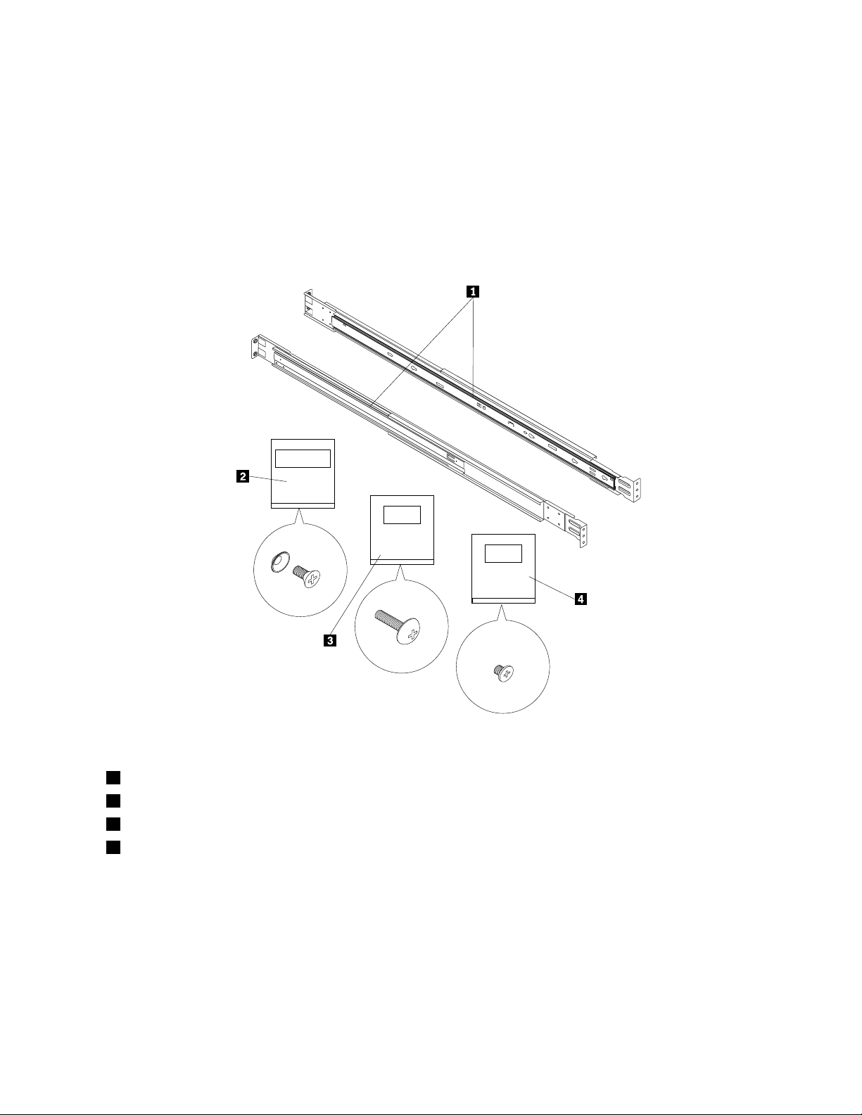
Railkitpackage
M5+WASHER
M5X20L
M4X4L
Beforeyoubegintherackinstallation,removeallthepartsfromtherailkitpackageshippedwithyour
serverandlayallthepartsonaworkingsurface.
Therailkitpackagecontainsthefollowingparts.Contactyourplaceofpurchaseifanypartismissingor
damaged.
Figure1.Partsintherailkitpackage
1Sliderails(2)
2ScrewbagmarkedwithM5+WASHER(containingeightatheadM5x10screwsandeightwashers)
3ScrewbagmarkedwithM5X20L(containingtwopanheadM5x20screws)
4ScrewbagmarkedwithM4X4L(containingfouratheadM4x4screws)
3
Page 4
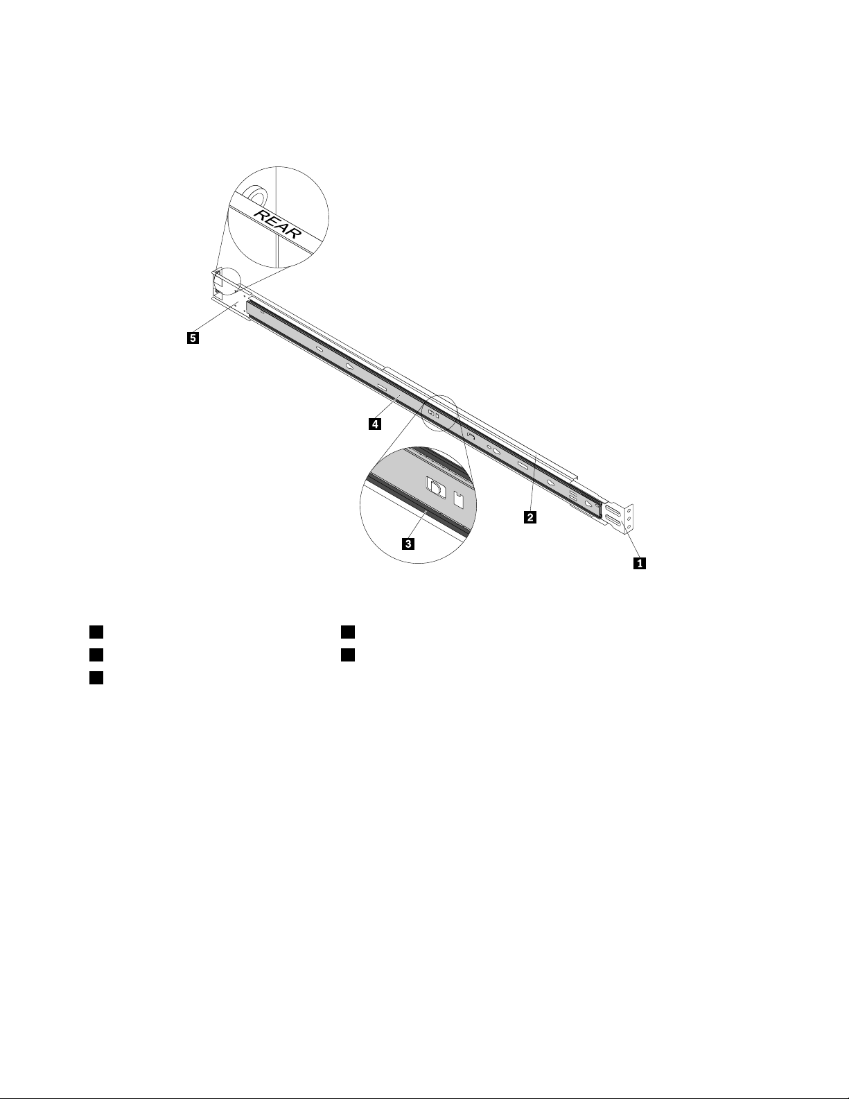
Thetwosliderailscontainedintherailkitpackagearethesame.Theillustrationbelowshowsonlythe
componentsofone.
Figure2.Sliderailcomponents
1Frontmountingbracket4Innerrail
2Outerrail5Rearmountingbracket(markedwithREARonbothsides)
3Ballrail(theballbearingrailsandwiched
betweentheouterrailandtheinnerrailto
provideasmoothslidingmovement)
Installingtheserverintoarackcabinet
Toinstalltheserverintoarackcabinet,dothefollowing:
1.Removeallthepartsfromtherailkitpackageshippedwithyourserverandlayallthepartsonaworking
surface.See“Railkitpackage”onpage3.
2.Thestretchingrangeofanouterrailis60cm(23.6inches)to82cm(32.3inches).Measuretherack
beforetheinstallationtoensurethattherackcanaccommodatetheouterrail.
3.Foreachsliderail,separatetheinnerrailfromtheouterrailbydoingthefollowing:
Note:Slidetherailsstraightoutanddonottwisttherailswhenseparatingthem.
4
Page 5
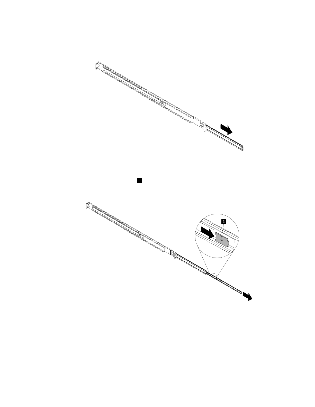
a.Holdasliderailassemblybyonehandandcarefullyslideboththeballrailandtheinnerrailoutof
thefrontoftheassemblyuntiltheballrailislockedandcannotbepulledoutfurther.
Figure3.Slidingtheballrailwiththeinnerrailoutoftheouterrail
b.Carefullyslidetheinnerrailoutoftheballrailuntiltheinnerrailislockedandcannotbepulledout
further.Then,pressthereleasetab
1ontheinnerrailinthedirectionasshownandcompletely
removetheinnerrailfromtheballrail.
Figure4.Removingtheinnerrailfromtheballrail
5
Page 6

c.Pressthemetallever1ontheballrailinthedirectionasshownandslidetheballrailbackinto
theouterrail.Theballrailisanintegratedpartoftheouterrailanddonottrytoremovetheball
railfromtheouterrail.
Figure5.Slidingtheballrailintotheouterrail
4.Afterseparatingtheinnerrailsfromtheouterrails,placealltherailsonaworkingsurface.
Figure6.Outerrailsandinnerrails
1Twoouterrails2Twoinnerrails
6
Page 7

5.Removethetworackhandlesandfourscrewsfromthemountingearkitpackageshippedwithyour
serverandinstalltherackhandlesontheserverbytighteningthescrews.
Note:UseonlyscrewsprovidedbyLenovo.
Figure7.Installingtherackhandles
7
Page 8

6.Installaninnerrailonthetwomountingstudsononesideoftheserverandthenslidetheinnerrailto
thebackoftheserveruntilitsnapsintoposition.InstalltwoM4x4screwstosecuretheinnerrailonthe
sideoftheserver.Then,installtheotherinnerrailtotheothersideoftheserverinthesameway.
Note:Notetheorientationoftheinnerrails.
Figure8.Installingtheinnerrailstobothsidesoftheserver
Figure9.Installingtheinnerrailstobothsidesoftheserver(sideview)
1Mountingstudholes(2)
2Innerrail
3Screwholes(2)
8
Page 9

7.Onafrontmountingangeoftherackcabinet,selectaproperrackmountingareafortheserver.Then,
positionthefrontmountingbracket1ofanouterrailontheinsideoftherackmountingarea2.
Note:Theholesinamountingangearedividedintogroupsbymeasuringmarks.Thethreeholes
betweentwoadjacentmeasuringmarksformagroup,whichindicates1Uspace.Notethemeasuring
marksonamountingangetohelpyoucorrectlyselectarackmountingareafortheserver.Formore
informationabouttheplacementoftheholesinamountingange,refertothedocumentationthat
comeswiththerackcabinet.
Figure10.Positioningthefrontmountingbracketoftheouterrailontheinsideoftherackmountingarea
9
Page 10

8.Makesurethatthefrontmountingbracketisushwiththeverticalmountingsurfaceandthescrew
holesinthefrontmountingbracketarealignedwiththecorrespondingholesintherackmountingarea.
Then,partiallytightentwoM5x10screwswithwasherstoholdthefrontoftheouterrailinposition.
Figure11.TighteningthetwoM5x10screws
10
Page 11

9.Stretchtherearmountingbrackettothebackoftherackandpositiontherearmountingbracketon
theinsideofthecorrespondingrackmountingareaontherearmountingange.Makesurethefront
endandrearendoftheouterrailareatthesamehorizontallevelandthetwoscrewholesintherear
mountingbracketarealignedwiththecorrespondingholesintherackmountingarea.Then,rmly
tightentwoM5x10screwswithwasherstosecuretheouterrailinplace.
Figure12.Securingtherearmountingbracketontherearmountingange
10.Returntothefrontmountingangeandrmlytightenthetwoscrewsthatholdthefrontoftheouterrail.
11.Repeatsteps6through9toinstalltheotherouterrailtotheoppositesideoftherack.
11
Page 12

12.Fullyextendtherailsonbothsidesoftherackbyslidingtheballrailsoutofthefrontoftheouterrails
untiltheballrailsarelockedandcannotbepulledoutfurther.Y oushouldhearaclickwhentheballrails
arelocked.Then,checkthefrontendsoftheballrailstoensuretheinnersideofeachballrailislocked
inpositionbythesmallmetallever
1beforeyouinstalltheserverintotherack.
Figure13.Fullyextendingtherailsonbothsidesoftherack
13.Liftuptheservernowequippedwithrackhandlesandinnerrailsonbothsidesandcarefullyinsertthe
innerrailsintotheextendedballrails.Then,slidetheinnerrailsstraightintotheballrailsuntiltheinner
railsarestoppedbytheretentiontabs.
Notes:
a.Beforeliftingupyourserver,see“Guidelines”onpage1todeterminewhethertwoormorepeople
arerequired.Strictlyfollowtheguidelinesforsafelifting.
b.Donotforcetheinnerrailsintotheballrails.Whentheyarealignedproperly,theywillengage
smoothly.
c.Youmustsupporttheserverfromthebottomtopreventitfromdroppingandensurethatitslidesin
horizontally.
12
Page 13

Figure14.Slidingtheserverwithinnerrailsintotheballrails
13
Page 14

14.Whentheinnerrailshavebeenstopped,presstheretentiontabs1onbothsidesinthedirectionas
shownandcontinuegentlyslidingtheserverintotherackuntilitisfullyseated.
Figure15.Pressingtheretentiontabsandslidingtheserverallthewayintotherack
14
Page 15

15.Tosecuretheserverintherack,installoneM5x20screwthroughtherackhandleonbothsidesofthe
server.Afterinstallingthescrews,theserverissecurelyseatedintherackandcannotslideoutunless
youremovethescrews.Thisensuressafetyandsecurity,especiallyinvibration-proneareas.
Figure16.Securingtheserverintherack
Toremovetheserverfromtherack,reversetheseinstructions.Storethisinformationwithyourserver
documentationforfutureuse.
15
Page 16

FirstEdition(December2010)
©CopyrightLenovo2010.
LENOVOproducts,data,computersoftware,andserviceshavebeendevelopedexclusivelyatprivateexpenseandare
soldtogovernmentalentitiesascommercialitemsasdenedby48C.F .R.2.101withlimitedandrestrictedrightsto
use,reproductionanddisclosure.
LIMITEDANDRESTRICTEDRIGHTSNOTICE:Ifproducts,data,computersoftware,orservicesaredeliveredpursuant
aGeneralServicesAdministration“GSA”contract,use,reproduction,ordisclosureissubjecttorestrictionssetforth
inContractNo.GS-35F-05925.
PrintedinChina
(1P)P/N:91Y1795
*91Y1795*
16
 Loading...