

Page 1

ThinkServer RD120 Ty pes 6444, 6445, 6446, and 6447
User Guid e
Page 2

Page 3

ThinkServer RD120 Ty pes 6444, 6445, 6446, and 6447
User Guid e
Page 4

Note:
Before using this information and the product it supports, read the general information in “Notices,” on page 91, and the Warranty
and Support Information document on the ThinkServer Documentation DVD.
Fourth Edition (April 2009)
© Copyright Lenovo 2008, 2009.
Portions © Copyright International Business Machines Corporation 2008.
All rights reserved.
LENOVO products, data, computer software, and services have been developed exclusively at private expense and
are sold to governmental entities as commercial items as defined by 48 C.F.R. 2.101 with limited and restricted rights
to use, reproduction and disclosure.
LIMITED AND RESTRICTED RIGHTS NOTICE: If products, data, computer software, or services are delivered
pursuant a General Services Administration ″GSA″ contract, use, reproduction, or disclosure is subject to restrictions
set forth in Contract No. GS-35F-05925.
Page 5

Contents
Safety . . . . . . . . . . . . . . . . . . . . . . . . . . . .v
Chapter 1. The ThinkServer RD120 server . . . . . . . . . . . . . .1
Related documentation . . . . . . . . . . . . . . . . . . . . . .2
Notices and statements in this document . . . . . . . . . . . . . . . .2
Features and specifications . . . . . . . . . . . . . . . . . . . .3
What your server offers . . . . . . . . . . . . . . . . . . . . . .4
Reliability, availability, and serviceability features . . . . . . . . . . . . .7
ThinkServer EasyStartup . . . . . . . . . . . . . . . . . . . . . .8
Server controls, LEDs, and power . . . . . . . . . . . . . . . . . .8
Front view . . . . . . . . . . . . . . . . . . . . . . . . . .8
Rear view . . . . . . . . . . . . . . . . . . . . . . . . . .10
Server power features . . . . . . . . . . . . . . . . . . . . .12
Chapter 2. Installing optional devices . . . . . . . . . . . . . . . .15
Server components . . . . . . . . . . . . . . . . . . . . . . .15
System-board optional-device connectors . . . . . . . . . . . . . .18
PCI riser-card adapter connectors . . . . . . . . . . . . . . . . .19
Power-backplane-board connectors . . . . . . . . . . . . . . . .19
System-board internal cable connectors . . . . . . . . . . . . . . .20
System-board external connectors . . . . . . . . . . . . . . . . .21
System-board switches and jumpers . . . . . . . . . . . . . . . .22
System-board LEDs . . . . . . . . . . . . . . . . . . . . . .24
Riser-card assembly LEDs . . . . . . . . . . . . . . . . . . .25
Diagnostics panel . . . . . . . . . . . . . . . . . . . . . . .26
Installation guidelines . . . . . . . . . . . . . . . . . . . . . .29
System reliability guidelines . . . . . . . . . . . . . . . . . . .30
Working inside the server with the power on . . . . . . . . . . . . .30
Handling static-sensitive devices . . . . . . . . . . . . . . . . .31
Removing the cover . . . . . . . . . . . . . . . . . . . . . . .31
Removing the riser-card assembly . . . . . . . . . . . . . . . . . .32
Installing the riser-card assembly . . . . . . . . . . . . . . . . . .34
Removing the microprocessor air baffle . . . . . . . . . . . . . . . .34
Installing the microprocessor air baffle . . . . . . . . . . . . . . . .36
Removing the DIMM air baffle . . . . . . . . . . . . . . . . . . .37
Installing the DIMM air baffle . . . . . . . . . . . . . . . . . . . .38
Installing an adapter . . . . . . . . . . . . . . . . . . . . . . .39
Removing an adapter . . . . . . . . . . . . . . . . . . . . . .43
Replacing the RAID SAS controller . . . . . . . . . . . . . . . . .45
Installing a hard disk drive . . . . . . . . . . . . . . . . . . . . .47
Removing a hard disk drive . . . . . . . . . . . . . . . . . . . .49
Installing an optional tape drive . . . . . . . . . . . . . . . . . . .50
Installing a SATA tape drive in a 3.5-inch model server . . . . . . . . .50
Installing a SATA tape drive in a 2.5-inch model server . . . . . . . . .53
Installing a microprocessor . . . . . . . . . . . . . . . . . . . .54
Installing a memory module . . . . . . . . . . . . . . . . . . . .60
Memory mirroring . . . . . . . . . . . . . . . . . . . . . . .62
Online-spare memory . . . . . . . . . . . . . . . . . . . . .63
Removing a memory module . . . . . . . . . . . . . . . . . . . .65
Installing a hot-swap power supply . . . . . . . . . . . . . . . . .65
Removing a hot-swap power supply . . . . . . . . . . . . . . . . .68
Installing a fan . . . . . . . . . . . . . . . . . . . . . . . . .68
Removing a fan . . . . . . . . . . . . . . . . . . . . . . . .69
© Lenovo 2008, 2009. Portions © IBM Corp. 2008. iii
Page 6

Removing the fan-bracket assembly . . . . . . . . . . . . . . . . .70
Installing the fan-bracket assembly . . . . . . . . . . . . . . . . .72
Replacing the CD-RW/DVD drive . . . . . . . . . . . . . . . . . .73
Completing the installation . . . . . . . . . . . . . . . . . . . . .74
Installing the cover . . . . . . . . . . . . . . . . . . . . . .75
Connecting the cables . . . . . . . . . . . . . . . . . . . . .75
Updating the server configuration . . . . . . . . . . . . . . . . .76
Chapter 3. Configuring the server . . . . . . . . . . . . . . . . .79
Using the Configuration/Setup Utility program . . . . . . . . . . . . .79
Starting the Configuration/Setup Utility program . . . . . . . . . . . .80
Configuration/Setup Utility menu choices . . . . . . . . . . . . . .80
Passwords . . . . . . . . . . . . . . . . . . . . . . . . .84
Using the RAID Configuration Utility program . . . . . . . . . . . . . .87
Starting the RAID Configuration Utility program . . . . . . . . . . . .87
RAID Configuration Utility menu choices . . . . . . . . . . . . . .88
Configuring the controller . . . . . . . . . . . . . . . . . . . .88
Viewing the configuration . . . . . . . . . . . . . . . . . . . .88
Using the baseboard management controller . . . . . . . . . . . . . .88
Using the baseboard management controller utility programs . . . . . . .89
Configuring the Gigabit Ethernet controllers . . . . . . . . . . . . . .89
Appendix. Notices . . . . . . . . . . . . . . . . . . . . . . .91
Trademarks . . . . . . . . . . . . . . . . . . . . . . . . . .92
Important notes . . . . . . . . . . . . . . . . . . . . . . . . .92
Waste electrical and electronic equipment (WEEE) notices . . . . . . . . .93
Recycling statements for Japan . . . . . . . . . . . . . . . . . . .94
Battery return program . . . . . . . . . . . . . . . . . . . . . .95
German Ordinance for Work gloss statement . . . . . . . . . . . . . .96
Electronic emission notices . . . . . . . . . . . . . . . . . . . .96
Federal Communications Commission (FCC) statement . . . . . . . . .96
Industry Canada Class A emission compliance statement . . . . . . . .96
Avis de conformité à la réglementation d’Industrie Canada . . . . . . . .97
Australia and New Zealand Class A statement . . . . . . . . . . . .97
United Kingdom telecommunications safety requirement . . . . . . . . .97
European Union EMC Directive conformance statement . . . . . . . . .97
Taiwanese Class A warning statement . . . . . . . . . . . . . . .97
Chinese Class A warning statement . . . . . . . . . . . . . . . .98
Japanese Voluntary Control Council for Interference (VCCI) statement . . .98
Lenovo product service information for Taiwan . . . . . . . . . . . .98
Index . . . . . . . . . . . . . . . . . . . . . . . . . . . .99
iv ThinkServer RD120 Types 6444, 6445, 6446, and 6447: User Guide
Page 7
Safety
Before installing this product, read the Safety Information.
Antes de instalar este produto, leia as Informações de Segurança.
Pred instalací tohoto produktu si prectete prírucku bezpecnostních instrukcí.
Læs sikkerhedsforskrifterne, før du installerer dette produkt.
Lees voordat u dit product installeert eerst de veiligheidsvoorschriften.
Ennen kuin asennat tämän tuotteen, lue turvaohjeet kohdasta Safety Information.
Avant d’installer ce produit, lisez les consignes de sécurité.
Vor der Installation dieses Produkts die Sicherheitshinweise lesen.
Prima di installare questo prodotto, leggere le Informazioni sulla Sicurezza.
Les sikkerhetsinformasjonen (Safety Information) før du installerer dette produktet.
Antes de instalar este produto, leia as Informações sobre Segurança.
Antes de instalar este producto, lea la información de seguridad.
Läs säkerhetsinformationen innan du installerar den här produkten.
© Lenovo 2008, 2009. Portions © IBM Corp. 2008. v
Page 8

Important:
Each caution and danger statement in this document is labeled with a number. This
number is used to cross reference an English language caution or danger
statement with translated versions of the caution or danger statement in the Safety
Information document, which is provided on the ThinkServer Documentation DVD.
For example, if a caution statement is labeled “Statement 1,” translations for that
caution statement are in the Safety Information document under “Statement 1.”
Be sure to read all caution and danger statements in this document before you
perform the procedures. Read any additional safety information that comes with any
optional device before you install the device.
vi ThinkServer RD120 Types 6444, 6445, 6446, and 6447: User Guide
Page 9
Statement 1:
DANGER
Electrical
current from power, telephone, and communication cables is
hazardous.
To avoid a shock hazard:
v Do not connect or disconnect any cables or perform installation,
maintenance, or reconfiguration of this product during an electrical
storm.
v Connect all power cords to a properly wired and grounded electrical
outlet.
v Connect to properly wired outlets any equipment that will be attached to
this product.
v When possible, use one hand only to connect or disconnect signal
cables.
v Never turn on any equipment when there is evidence of fire, water, or
structural damage.
v Disconnect the attached power cords, telecommunications systems,
networks, and modems before you open the device covers, unless
instructed otherwise in the installation and configuration procedures.
v Connect and disconnect cables as described in the following table when
installing, moving, or opening covers on this product or attached
devices.
To Connect: To Disconnect:
1. Turn everything OFF.
2. First, attach all cables to devices.
3. Attach signal cables to connectors.
4. Attach power cords to outlet.
1. Turn everything OFF.
2. First, remove power cords from outlet.
3. Remove signal cables from connectors.
4. Remove all cables from devices.
5. Turn device ON.
Safety vii
Page 10

Statement 2:
CAUTION:
When replacing the lithium battery, use only the battery recommended by the
manufacturer. If your system has a module containing a lithium battery,
replace it only with the same module type made by the same manufacturer.
The battery contains lithium and can explode if not properly used, handled, or
disposed of.
Do not:
v Throw or immerse into water
v Heat to more than 100°C (212°F)
v Repair or disassemble
Dispose
of the battery as required by local ordinances or regulations.
viii ThinkServer RD120 Types 6444, 6445, 6446, and 6447: User Guide
Page 11
Statement 3:
CAUTION:
When laser products (such as CD drives, DVD drives, fiber optic devices, or
transmitters) are installed, note the following:
v Do not remove the covers. Removing the covers of the laser product could
result in exposure to hazardous laser radiation. There are no serviceable
parts inside the device.
v Use of controls or adjustments or performance of procedures other than
those specified herein might result in hazardous radiation exposure.
DANGER
laser products contain an embedded Class 3A or Class 3B laser
Some
diode. Note the following.
Laser radiation when open. Do not stare into the beam, do not view directly
with optical instruments, and avoid direct exposure to the beam.
Class 1 Laser Product
Laser Klasse 1
Laser Klass 1
Luokan 1 Laserlaite
Appareil A Laser de Classe 1
`
Safety ix
Page 12
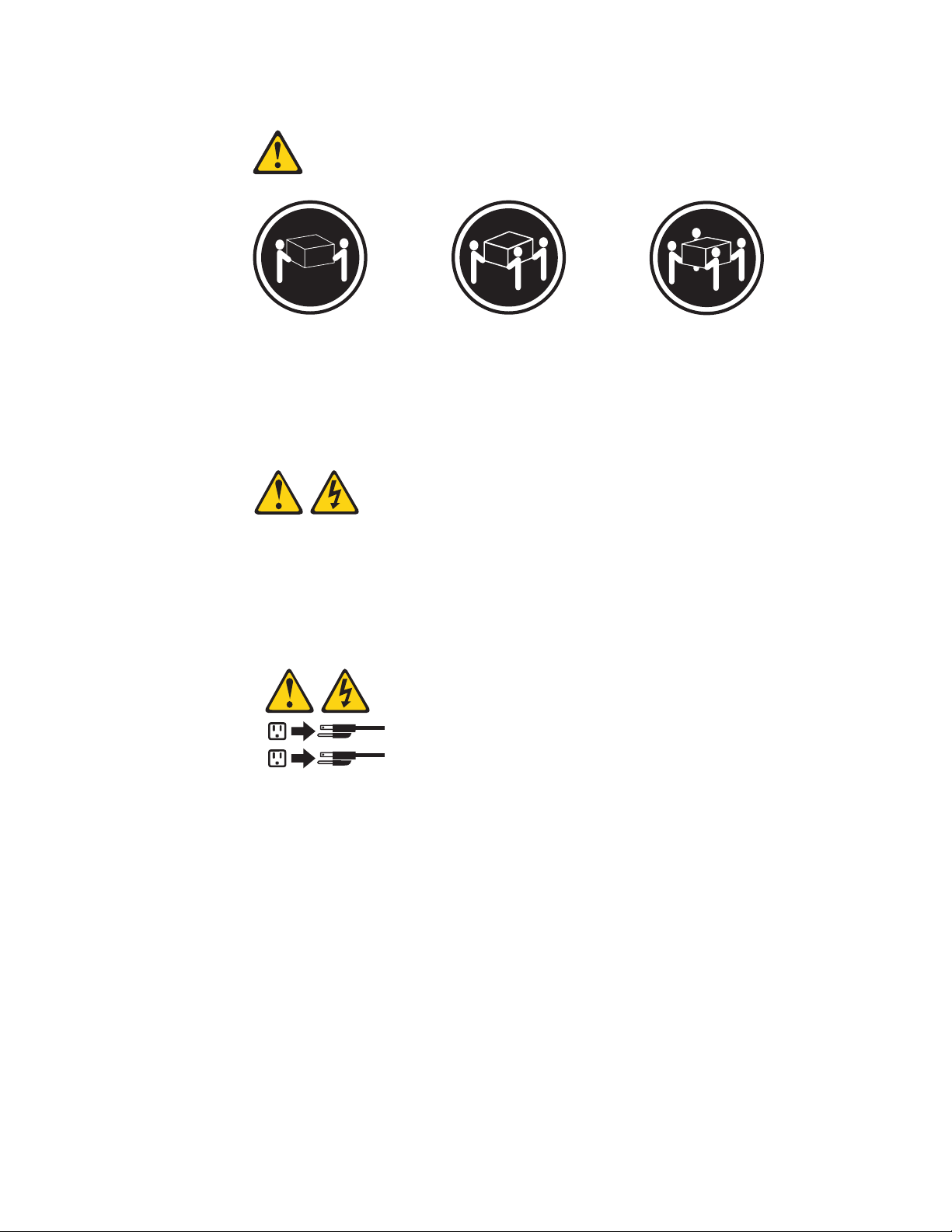
Statement 4:
≥ 18 kg (39.7 lb) ≥ 32 kg (70.5 lb) ≥ 55 kg (121.2 lb)
CAUTION:
Use safe practices when lifting.
Statement 5:
CAUTION:
The power control button on the device and the power switch on the power
supply do not turn off the electrical current supplied to the device. The device
also might have more than one power cord. To remove all electrical current
from the device, ensure that all power cords are disconnected from the power
source.
2
1
x ThinkServer RD120 Types 6444, 6445, 6446, and 6447: User Guide
Page 13
Statement 8:
CAUTION:
Never remove the cover on a power supply or any part that has the following
label attached.
Hazardous voltage, current, and energy levels are present inside any
component that has this label attached. There are no serviceable parts inside
these components. If you suspect a problem with one of these parts, contact
a service technician.
Statement 12:
CAUTION:
The following label indicates a hot surface nearby.
Statement 13:
DANGER
Overloading
a branch circuit is potentially a fire hazard and a shock hazard
under certain conditions. To avoid these hazards, ensure that your system
electrical requirements do not exceed branch circuit protection
requirements. Refer to the information that is provided with your device for
electrical specifications.
Safety xi
Page 14

Statement 15:
CAUTION:
Make sure that the rack is secured properly to avoid tipping when the server
unit is extended.
xii ThinkServer RD120 Types 6444, 6445, 6446, and 6447: User Guide
Page 15
Chapter 1. The ThinkServer RD120 server
The Lenovo® ThinkServer™ RD120 (Machine Types 6444, 6445, 6446, and 6447)
server is a 5-U-high, high-performance server. It is ideally suited for networking
environments that require superior microprocessor performance, improved systems
management, and flexible memory and data management.
The server has two model styles, which are based on the size and number of hard
disk drive bays:
v The 3.5-inch models have six 3.5-inch hot-swap hard disk drive bays. Install only
3.5-inch drives in these models. If you intend to install an optional tape drive, the
tape drive will occupy two of the six 3.5-inch drive bays.
v The 2.5-inch models have eight 2.5-inch hot-swap hard disk drive bays and one
3.5-inch tape-drive bay. Install only 2.5-inch hard disk drives and an optional
3.5-inch tape drive in these models.
Throughout this documentation, the terms 2.5-inch models and 3.5-inch models will
be used to distinguish between the server styles.
Performance, ease of use, reliability, and expansion capabilities were key
considerations in the design of the server. These design features make it possible
for you to customize the system hardware to meet your needs today and provide
flexible expansion capabilities for the future.
The server comes with a limited warranty. For information about the terms of the
warranty and getting service and assistance, see the Warranty and Support
Information document.
You can obtain up-to-date information about the server and other Lenovo server
products at: http://www.lenovo.com/thinkserver.
Attention: The information in this document regarding installing and removing
power supplies and connecting and disconnecting power refers to ac power
supplies only. If the server contains dc power supplies, see the documentation that
comes with the dc power supplies. In a dc power environment, only trained service
personnel other than Lenovo service technicians are authorized to connect or
disconnect power to the dc power supply and to install and remove a dc power
supply.
1. Racks are measured in vertical increments of 4.45 cm (1.75 inches) each. Each increment is called a ″U.″ A 1-U-high device is
1.75 inches tall.
© Lenovo 2008, 2009. Portions © IBM Corp. 2008. 1
Page 16

Related documentation
This User Guide contains general information about the server, including how to
install supported optional devices and how to configure the server. The following
documentation also comes with the server:
v Installation Guide
This document is in Portable Document Format (PDF) on the ThinkServer
Documentation DVD. It contains instructions for setting up the server and basic
instructions for installing some optional devices.
v Warranty and Support Information
This document is in PDF on the ThinkServer Documentation DVD. It contains
information about the terms of the warranty and getting service and assistance.
v Safety Information
This document is in PDF on the ThinkServer Documentation DVD. It contains
translated caution and danger statements. Each caution and danger statement
that appears in the documentation has a number that you can use to locate the
corresponding statement in your language in the Safety Information document.
v Rack Installation Instructions
This document is in PDF on the ThinkServer Documentation DVD. It contains
instructions for installing the server in a rack.
v Hardware Maintenance Manual
This document is available in English as a PDF on the ThinkServer
Documentation DVD. The most current version of the Hardware Maintenance
Manual is available on the Lenovo Support Web site. It contains information to
help you solve problems yourself, and it contains information for service
technicians.
Depending
on the server model, additional documentation might be included on the
ThinkServer Documentation DVD.
The server might have features that are not described in the documentation that
comes with the server. The documentation might be updated occasionally to include
information about those features, or technical updates might be available to provide
additional information that is not included in the server documentation. These
updates are available from the Lenovo Web site. To check for updated
documentation and technical updates, complete the following steps.
Note: Changes are made periodically to the Lenovo Web site. The actual
procedure might vary slightly from what is described in this document.
1. Go to: http://www.lenovo.com/support.
2. Enter your product number (machine type and model number) or select Servers
and Storage from the Select your product list.
3. From Family list, select ThinkServer RD120, and click Continue.
Notices and statements in this document
The caution and danger statements in this document are also in the multilingual
Safety Information document, which is on the ThinkServer Documentation DVD.
Each statement is numbered for reference so you can locate the corresponding
statement in your language in the Safety Information document.
The following notices and statements are used in this document:
2 ThinkServer RD120 Types 6444, 6445, 6446, and 6447: User Guide
Page 17

v Note: These notices provide important tips, guidance, or advice.
v Important: These notices provide information or advice that might help you avoid
inconvenient or problem situations.
v Attention: These notices indicate potential damage to programs, devices, or
data. An attention notice is placed just before the instruction or situation in which
damage might occur.
v Caution: These statements indicate situations that can be potentially hazardous
to you. A caution statement is placed just before the description of a potentially
hazardous procedure step or situation.
v Danger: These statements indicate situations that can be potentially hazardous
to you. A danger statement is placed just before the description of a potentially
lethal or extremely hazardous procedure step or situation.
Features and specifications
The following information is a summary of the features and specifications of the
server. Depending on the server model, some features might not be available, or
some specifications might not apply.
Racks are marked in vertical increments of 4.45 cm (1.75 inches). Each increment
is referred to as a unit, or "U." A 1-U-high device is 1.75 inches tall.
Notes:
1. Power consumption and heat output vary depending on the number and type of
optional features that are installed and the power-management optional features
that are in use.
2. The sound levels were measured in controlled acoustical environments
according to the procedures specified by the American National Standards
Institute (ANSI) S12.10 and ISO 7779 and are reported in accordance with ISO
9296. Actual sound-pressure levels in a given location might exceed the
average values stated because of room reflections and other nearby noise
sources. The declared sound-power levels indicate an upper limit, below which
a large number of computers will operate.
Chapter 1. The ThinkServer RD120 server 3
Page 18
Table 1. Features and specifications
Microprocessor:
v Intel® Xeon® FC-LGA 771 dual-core
with 4 MB Level-2 cache or
quad-core with 8 MB (2x4 MB)
Level-2 cache
v Support for up to two
microprocessors
v Support for Intel Extended Memory
64 Technology (EM64T)
Notes:
1. Use the Configuration/Setup Utility
program to determine the type and
speed of the microprocessors.
2. For a list of supported
microprocessors, go to
http://www.lenovo.com/thinkserver.
Memory:
v Twelve DIMM connectors
v Minimum: 1 GB
v Maximum: 48 GB
v Type: Fully buffered DIMM (FBD)
v Sizes: 1 GB, 2 GB, or 4 GB (when
v Advanced ECC supported
Drives:
DVD combination
Expansion bays:
v Hot-swap hard disk drive bays: SAS
Expansion
v Two PCI Express x8 slots (x4 lanes)
v Support for either of the following
PC2-5300 DIMMS only
available), in pairs
CD/DVD: IDE 24x CD-RW/ 8x
only. Number and size depend on the
server model. One of the following
configurations:
– Six 3.5-inch drive bays
– Eight 2.5-inch drive bays
– One 5.25-inch Ultrabay
™
Enhanced bay (CD-RW/DVD drive
installed)
slots :
on system board (low profile)
optional riser cards:
– Riser cards with two PCI Express
x8 slots (x8 lanes) (standard)
– Riser card with two 133
MHz/64-bit PCI-X slots
Hot-swap fans:
v Standard: Five
v Maximum: Te n - provide redundant
cooling
Hot-swap
power supplies: 835 watts
(100 - 240 V ac):
v Minimum: One
v Maximum: Two - provide redundant
power
(2U):
Size
v Height: 85.4 mm (3.36 in.)
v Depth: 705 mm (27.8 in.)
v Width: 443.6 mm (17.5 in.)
v Weight: 21.09 kg (46.5 lb) to 29.03 kg
(64 lb) depending upon configuration
Integrated
functions:
v Baseboard management controller
(BMC)
v Two Broadcom 10/100/1000 Ethernet
controllers with TCP/IP Offload Engine
(TOE) support
v One RAID controller, active only when
an 8k or 8k-l SAS controller is installed
v One serial port
v One serial-attached SCSI (SAS)
controller
v Seven Universal Serial Bus (USB) ports
(two on front and four on rear, plus one
internal), v2.0 supporting v1.1
v Two video ports (one on front and one
on rear of server)
v One internal serial AGA (SATA )
connector
v Support for Remote Supervisor Adapter
II SlimLine (option)
In messages and documentation,
Note:
the term service processor refers to the
baseboard management controller or the
optional Remote Supervisor Adapter II
SlimLine.
Video controller:
v ATI RN50 video on system board
v Compatible with SVGA and VGA
v 16 MB DDR video memory
Acoustical
noise emissions:
v Declared sound power, idle: 6.8 bel
v Declared sound power, operating: 6.8
bel
ServeRAID SAS controller:
v ServeRAID™-8k-l SAS Controller that
supports RAID levels 0, 1, 10
v Upgradeable to ServeRAID-8k SAS
Controller, 256 MB with battery backup, that
supports RAID levels 0, 1, 1E, 5, 6, and 10
Environment:
v Air temperature:
– Server on: 10° to 35°C (50° to 95°F)
Altitude: 0 to 914.4 m (3000 ft)
– Server off: 10° to 43°C (50° to 109.4°F)
Maximum altitude: 2133.6 m (7000 ft)
– Shipping: -40° to 60°C (-40° to 140°F)
v Humidity (operating and storage):
– Server on: 8% to 80%
– Server off: 8% to 80%
Heat output:
Approximate heat output in British thermal
units (Btu) per hour:
v Minimum configuration: 1230 Btu per hour
(360 watts)
v Maximum configuration: 3390 Btu per hour
(835 watts)
Electrical
input with hot-swap ac power
supplies:
v Sine-wave input (50 or 60 Hz) required
v Input voltage and frequency ranges
automatically selected
v Input voltage low range:
– Minimum: 100 V ac
– Maximum: 127 V ac
Input voltage high range:
v
– Minimum: 200 V ac
– Maximum: 240 V ac
v Input kilovolt-amperes (kVA) approximately:
– Minimum: 0.29 kVA (all models)
– Maximum: 1.00 kVA
What your server offers
The server uses the following features and technologies:
v Baseboard management controller
The baseboard management controller (BMC) provides basic service-processor
environmental monitoring functions. If an environmental condition exceeds a
4 ThinkServer RD120 Types 6444, 6445, 6446, and 6447: User Guide
Page 19

threshold or if a system component fails, the baseboard management controller
lights LEDs to help you diagnose the problem.
v ThinkServer EasyStartup DVD
The Lenovo ThinkServer EasyStartup DVD that comes with the server provides
programs to help you set up the server and install an operating system. The
EasyStartup™ program detects installed hardware devices and guides you
through the process of creating a response file and performing an unattended
installation of the operating system and associated device drivers.
For more information about the ThinkServer EasyStartup DVD, refer to the
ThinkServer RD120 Installation Guide.
v EasyManage software
ThinkServer EasyManage software helps you maintain high performance while
limiting downtime. Through a single console you can monitor and configure alerts
for security and performance, perform hardware failure prediction, deploy
operating systems and software, and monitor software licenses. You can
download and install the EasyManage software from the Lenovo Support Web
site (http://www.lenovo.com/support). For information about installing
EasyManage software, refer to the Installation Guide.
v Diagnostics CD
The Diagnostics CD provided with your server contains the diagnostic programs
for testing the major components of the server. For additional information about
the Diagnostics CD, see the Hardware Maintenance Manual on the ThinkServer
Documentation DVD.
v Integrated network support
The server comes with two integrated Broadcom Gigabit Ethernet controllers,
which support connection to a 10-Mbps, 100-Mbps, or 1000-Mbps network. For
more information, see “Configuring the Gigabit Ethernet controllers” on page 89.
v Large data-storage and hot-swap capability
The 3.5-inch model server supports up to six slim, 3.5-inch hot-swap hard disk
drives in the hot-swap bays. The 2.5-inch model server supports up to eight
2.5-inch hot-swap hard disk drives in the hot-swap bays. With the hot-swap
feature, you can add, remove, or replace hard disk drives without turning off the
server.
Chapter 1. The ThinkServer RD120 server 5
Page 20

v Easy LED Diagnostics
Easy LED Diagnostics provides LEDs to help you diagnose problems. For more
information, see the section about Easy LED Diagnostics in the Hardware
Maintenance Manual.
v Memory mirroring
Memory mirroring improves the reliability of memory by writing information to the
main memory and redundant locations in a mirrored pair of DIMMs.
v Online-spare memory
Online-spare memory disables a failed pair of DIMMs from the system
configuration and activates an online-spare DIMM pair to replace the failed pair.
v PCI Express adapter capabilities
The server has two slots for low-profile PCI Express x4 adapters. These slots
accept x8 adapters, but the adapters will operate as x4 adapters. The server also
has two slots for PCI Express x8 adapters (on the riser card, full-height, one
full-length and one half-length).
Note: You can replace these PCI Express x8 slots with PCI-X 133 MHz slots by
replacing the PCI Express riser-card assembly with an optional PCI-X riser-card
assembly.
v Redundant connection
The addition of an optional network interface card (NIC) provides a failover
capability to a redundant Ethernet connection. If a problem occurs with the
primary Ethernet connection, all Ethernet traffic that is associated with the
primary connection is automatically switched to the redundant NIC. If the
applicable device drivers are installed, this switching occurs without data loss and
without user intervention.
v Redundant cooling and power capabilities
The server supports up to 10 hot-swap fans, in multiples of 5, which provide
redundant cooling. Redundant cooling enables continued operation if one of the
fans fails. The server supports up to two 835-watt ac power supplies, which
provide redundancy and hot-swap capability for a typical configuration. If the
maximum load on the server is less than 835 watts and a problem occurs with
one of the power supplies, the other power supply can meet the power
requirements.
Note: A 700-watt-48 volt dc power supply option may be available. The dc
power supplies provide redundancy but no hot-swap capability.
v RAID support
The server supports an internal ServeRAID-8k or 8k-l SAS Controller, which is
required for you to use the hot-swap hard disk drives and to create redundant
array of independent disks (RAID) configurations.
6 ThinkServer RD120 Types 6444, 6445, 6446, and 6447: User Guide
Page 21

v Systems-management capabilities
The server supports an optional IBM Remote Supervisor Adapter II SlimLine.
When you use this adapter, you can manage the functions of the server locally
and remotely. The Remote Supervisor Adapter II SlimLine also provides system
monitoring, event recording, and dial-out alert capability.
v TCP/IP offload engine (TOE) support
The Ethernet controllers in the server support TOE, which is a technology that
offloads the TCP/IP flow from the microprocessors and I/O subsystem to increase
the speed of the TCP/IP flow. When an operating system that supports TOE is
running on the server and TOE is enabled, the server supports TOE operation.
See the operating-system documentation for information about enabling TOE.
Note: As of the date of this document, the Linux operating system does not
support TOE.
Reliability, availability, and serviceability features
Three important computer design features are reliability, availability, and
serviceability (RAS). The RAS features help to ensure the integrity of the data that
is stored in the server, the availability of the server when you need it, and the ease
with which you can diagnose and repair problems.
The server has the following RAS features:
v Automatic error retry and recovery
v Automatic restart after a power failure
v Backup basic input/output system (BIOS) switching under the control of the
baseboard management controller
v Baseboard management controller (service processor)
v Built-in monitoring for fan, power, temperature, voltage, and power-supply
redundancy
v Cable-presence detection on most connectors
v Advanced ECC memory protection
v Error codes and messages
v Error correcting code (ECC) L2 cache and system memory
v Fully-buffered DIMMs (FBD) support
v Hot-swap cooling fans with speed-sensing capability
v Hot-swap hard disk drives
v Hot-spare memory
v Information and diagnostics LED panels
v Memory mirroring
v Menu-driven setup, system configuration, and redundant array of independent
disks (RAID) configuration programs
v Parity checking or CRC checking on the serially-attached SCSI (SAS) bus and
PCI buses
v Power management: compliance with Advanced Configuration and Power
Interface (ACPI)
v Power-on self-test (POST)
v Redundant Ethernet capabilities with failover support
v Redundant power supplies and redundant hot-swap fans (ac power supplies are
hot-swap)
v Remind button to temporarily turn off the system-error LED
v Remote system problem-determination support
v Standby voltage for systems-management features and monitoring
v Startup (boot) from LAN through Preboot Execution Environment (PXE) boot
agent utility or dynamic host configuration protocol/boot protocol (DHCP/BOOTP)
Chapter 1. The ThinkServer RD120 server 7
Page 22
v System auto-configuring from the configuration menu
v System error logging (POST and service processor)
v Systems-management monitoring through the Inter-Integrated Circuit (I2C) bus
v Upgradeable POST, BIOS, diagnostics, service processor microcode, and
read-only memory (ROM) resident code, locally or over the LAN
v Vital product data (VPD) on microprocessors, system board, power supplies,
SAS (hot-swap-drive) backplane, and power backplane
ThinkServer EasyStartup
The ThinkServer EasyStartup program simplifies the process of installing the
operating system and device drivers on your server by performing the following
tasks:
v Detects installed hardware devices
v Guides the network administrator through the process of creating a response file
v Enables the network administrator to create scripts or commands that run at the
end of the installation process
v Facilitates the installation of the ThinkServer EasyManage products
v Prepares the hard disk for installation
v Prompts the network administrator to insert the operating-system installation disc
v Initiates an unattended installation of the operating system and device drivers
EasyStartup program is provided with your server on DVD. The DVD is self
The
starting (bootable). The User Guide for the EasyStartup program is on the DVD and
can be accessed directly from the program’s interface. For additional information,
see the ThinkServer RD120 Installation Guide.
Server controls, LEDs, and power
This section describes the controls and light-emitting diodes (LEDs) and how to turn
the server on and off.
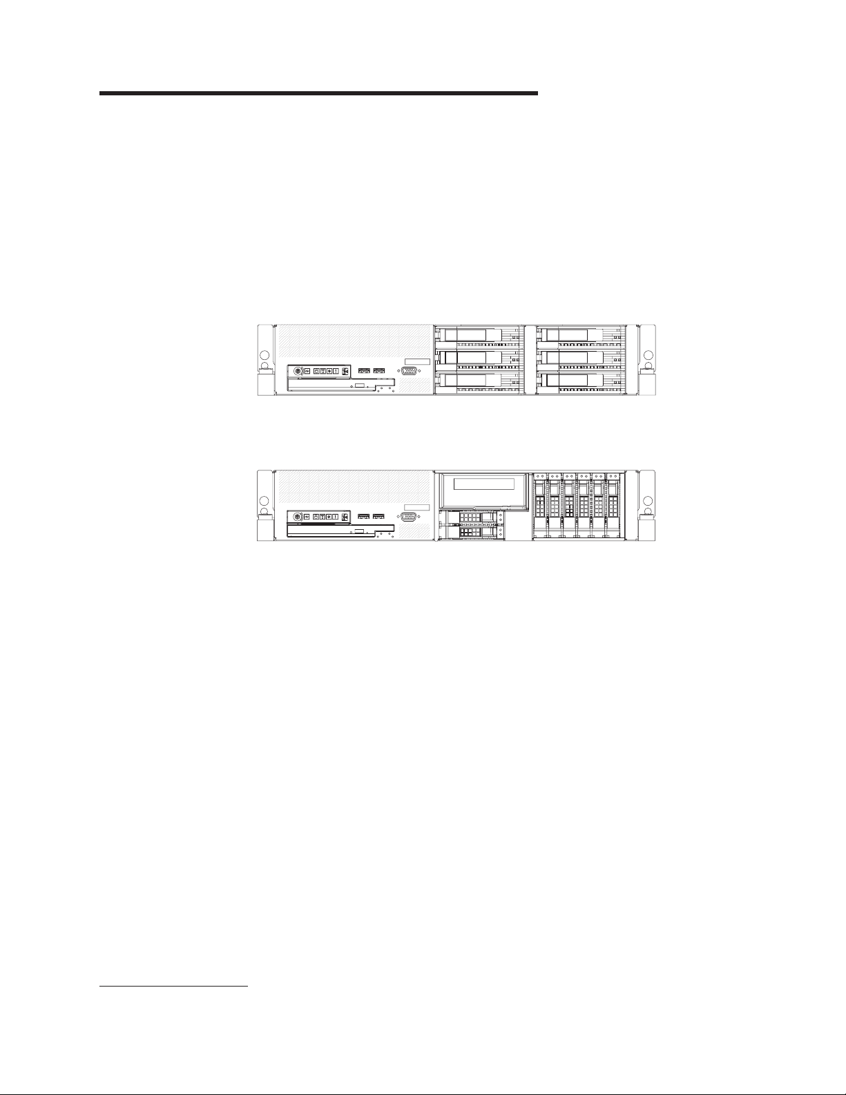
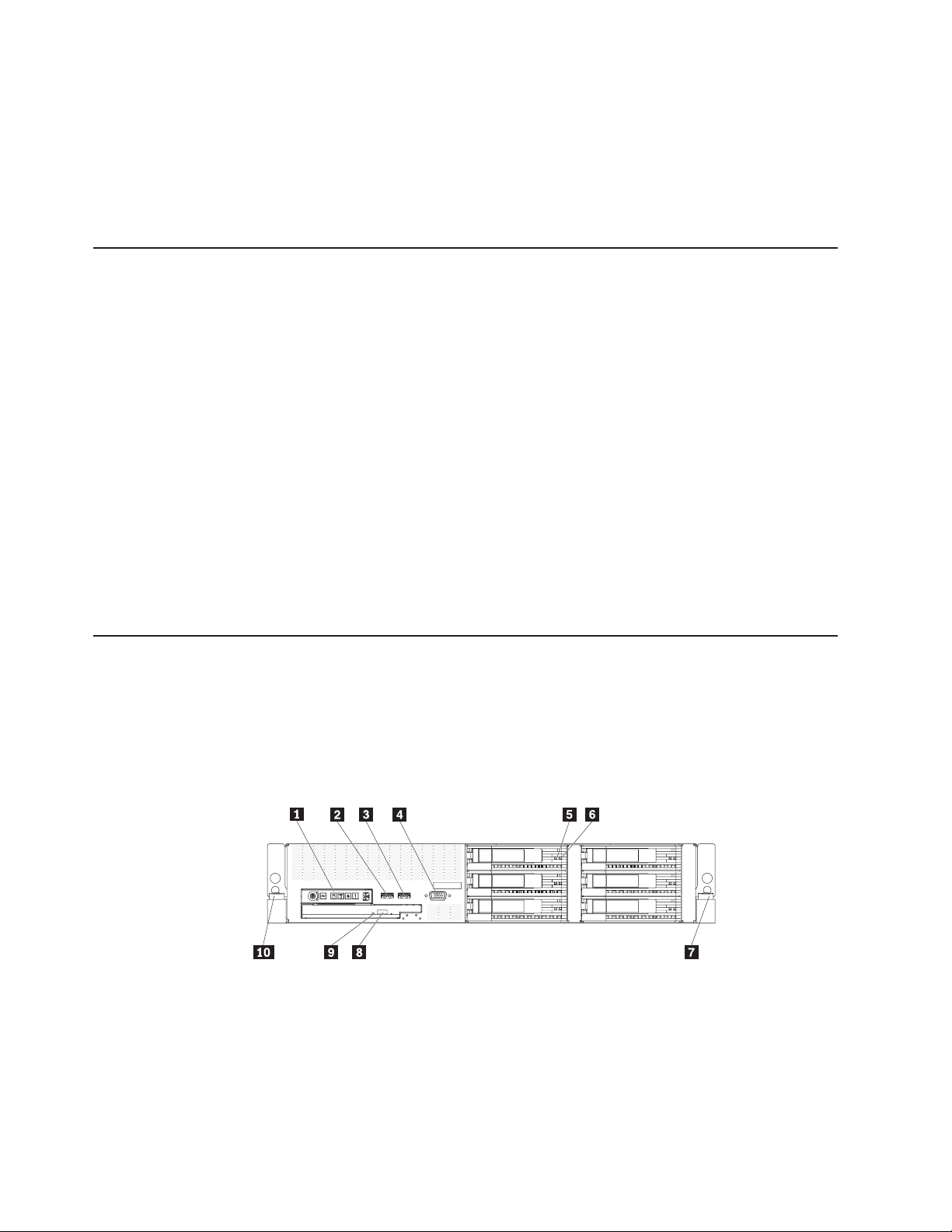
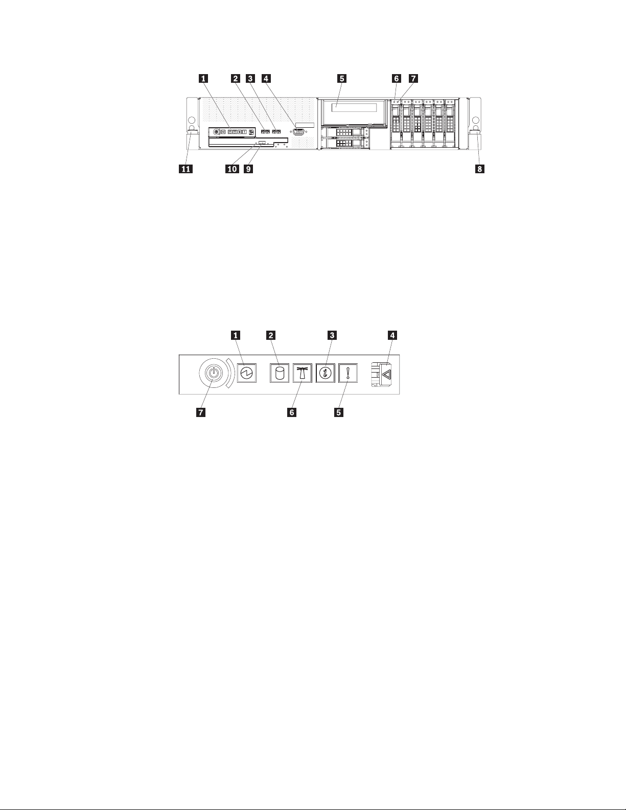
Front view
The following illustration shows the controls, light-emitting diodes (LEDs), and
connectors on the front of the 3.5-inch model server.
1 Operator information panel 6 Hard disk drive status LED (amber)
2 USB connector 7 Rack release latch
3 USB connector 8 CD/DVD eject button
4 Video connector 9 CD/DVD drive activity LED
5 Hard disk drive activity LED (green) 10 Rack release latch
The following illustration shows the controls, light-emitting diodes (LEDs), and
connectors on the front of the 2.5-inch model server.
8 ThinkServer RD120 Types 6444, 6445, 6446, and 6447: User Guide
Page 23
1 Operator information panel 7 Hard disk drive status LED (amber)
2 USB connector 8 Rack release latch
3 USB connector 9 CD/DVD eject button
4 Video connector 10 CD/DVD drive activity LED
5 Tape drive bay 11 Rack release latch
6 Hard disk drive activity LED (green)
Operator information panel: This panel contains controls, LEDs, and connectors.
The following illustration shows the controls, LEDs, and connectors on the operator
information panel.
1 Power-on LED 5 System error LED
2 Hard disk drive activity LED 7 System locator LED
3 Information LED 7 Power-control button
4 Release latch
The following controls, LEDs, and connectors are on the operator information panel:
v Power-control button: Press this button to turn the server on and off manually.
A power-control-button shield comes installed on the server to prevent the server
from being turned off accidentally.
v Power-on LED: When this LED is lit and not flashing, it indicates that the server
is turned on. When this LED is flashing, it indicates that the server is turned off
and still connected to a power source. When this LED is off, it indicates that
power is not present, or the power supply or the LED itself has failed.
Note: If this LED is off, it does not mean that there is no electrical power in the
server. The LED might be burned out. To remove all electrical power from the
server, you must disconnect the power cord from the electrical outlet.
Attention: In a dc power environment, only trained service personnel other than
Lenovo service technicians are authorized to connect or disconnect power to the
dc power supply. See the documentation that comes with each dc power supply.
v Hard disk drive activity LED: When this LED is flashing, it indicates that a hard
disk drive is in use.
v System-locator LED: Use this LED to visually locate the server among other
servers.
Chapter 1. The ThinkServer RD120 server 9
Page 24
v Information LED: When this LED is lit, it indicates that a noncritical event has
occurred. An LED on the diagnostics panel is also lit to help isolate the error.
v System-error LED: When this LED is lit, it indicates that a system error has
occurred. An LED on the diagnostics panel is also lit to help isolate the error.
v Release latch: Slide this latch to the left to access the diagnostics panel, which
is behind the operator information panel.
connectors: Connect a USB device, such as USB mouse, keyboard, or other
USB
USB device, to either of these connectors.
Video connector: Connect a monitor to this connector. The video connectors on
the front and rear of the server can be used simultaneously.
Hard disk drive activity LED: Each hot-swap hard disk drive has an activity LED.
When this LED is flashing, it indicates that the drive is in use.
Hard disk drive status LED: Each hot-swap hard disk drive has a status LED.
When this LED is lit, it indicates that the drive has failed. When this LED is flashing
slowly (one flash per second), it indicates that the drive is being rebuilt as part of a
RAID configuration. When the LED is flashing rapidly (three flashes per second), it
indicates that the controller is identifying the drive.
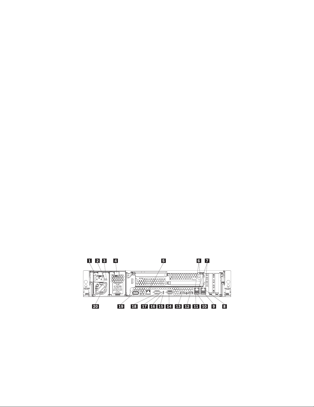
Rear view
CD/DVD-eject button: Press this button to release a CD or DVD from the
CD-RW/DVD drive.
CD/DVD drive activity LED: When this LED is lit, it indicates that the CD-RW/DVD
drive is in use.
Rack release latches: Press these latches to release the server from the rack.
The following illustration shows the connectors and LEDs on the rear of the server.
Attention: In a dc power environment, see the documentation that comes with
the dc power supply for information about the power-supply LEDs.
1 Power cord connector 11 Ethernet 2 connector
2 AC power LED 12 USB 2 connector
3 DC power LED 13 USB 1 connector
4 Power-supply filler panel 14 Video connector
5 Systems-management Ethernet
connector
6 Ethernet activity LEDs 16 System locator LED
7 Ethernet link LEDs 17 Power on LED
8 Ethernet connector 1 18 Serial connector
9 USB 4 connector 19 SAS connector
15 System error LED
10 ThinkServer RD120 Types 6444, 6445, 6446, and 6447: User Guide
Page 25

10 USB 3 connector 20 Power supply 1
Power-cord connector (ac power supply only): Connect the power cord to this
connector.
Attention: In a dc power environment, only trained service personnel other than
Lenovo service technicians are authorized to connect or disconnect power to the dc
power supply. See the documentation that comes with each dc power supply.
AC power LED: Each hot-swap power supply has an ac power LED and a dc
power LED. When the ac power LED is lit, it indicates that sufficient power is
coming into the power supply through the power cord. During typical operation, both
the ac and dc power LEDs are lit. For any other combination of LEDs, see the
Hardware Maintenance Manual on the ThinkServer Documentation DVD.
DC power LED: Each hot-swap power supply has a dc power LED and an ac
power LED. When the dc power LED is lit, it indicates that the power supply is
supplying adequate dc power to the system. During typical operation, both the ac
and dc power LEDs are lit. For any other combination of LEDs, see the Hardware
Maintenance Manual on the ThinkServer Documentation DVD.
Systems-management Ethernet connector: Use this connector to connect the
server to a network for systems-management information control. This connector is
active only if you have installed a Remote Supervisor Adapter II SlimLine, and it is
used only by the Remote Supervisor Adapter II SlimLine.
Ethernet activity LEDs: When these LEDs are lit, they indicate that the server is
transmitting to or receiving signals from the Ethernet LAN that is connected to the
Ethernet port.
Ethernet link LEDs: When these LEDs are lit, they indicate that there is an active
link connection on the 10BASE-T, 100BASE-TX, or 1000BASE-TX interface for the
Ethernet port.
Ethernet connectors: Use either of these connectors to connect the server to a
network.
USB connectors: Connect a USB device, such as USB mouse, keyboard, or other
USB device, to any of these connectors.
Video connector: Connect a monitor to this connector. The video connectors on
the front and rear of the server can be used simultaneously.
System-error LED: When this LED is lit, it indicates that a system error has
occurred. An LED on the diagnostics panel is also lit to help isolate the error.
System-locator LED: Use this LED to visually locate the server among other
servers.
Power-on LED: When this LED is lit and not flashing, it indicates that the server is
turned on. When this LED is flashing, it indicates that the server is turned off and
still connected to a power source. When this LED is off, it indicates that power is
not present, or the power supply or the LED itself has failed.
Chapter 1. The ThinkServer RD120 server 11
Page 26
Serial connector: Connect a 9-pin serial device to this connector. The serial port is
shared with the baseboard management controller (BMC). The BMC can take
control of the shared serial port to perform text console redirection and to redirect
serial traffic, using Serial over LAN (SOL).
SAS connector: Connect a serial-attached SCSI (SAS) device to this connector.
Server power features
When the server is connected to a power source but is not turned on, the operating
system does not run, and all core logic except for the service processor (the
baseboard management controller or optional Remote Supervisor Adapter II
SlimLine) is shut down; however, the server can respond to requests from the
service processor, such as a remote request to turn on the server. The power-on
LED flashes to indicate that the server is connected to power but is not turned on.
Turning on the server
Approximately 5 seconds after the server is connected to power, the power-control
button becomes active, and one or more fans might start running to provide cooling
while the server is connected to power. Yo u can turn on the server and start the
operating system by pressing the power-control button.
The server also can be turned on in any of the following ways:
v If a power failure occurs while the server is turned on, the server will restart
automatically when power is restored.
Turning off the server
When you turn off the server and leave it connected to power, the server can
respond to requests from the service processor, such as a remote request to turn
on the server. While the server remains connected to power, one or more fans
might continue to run. To remove all power from the server, you must disconnect it
from the power source.
Some operating systems require an orderly shutdown before you turn off the server.
See your operating-system documentation for information about shutting down the
operating system.
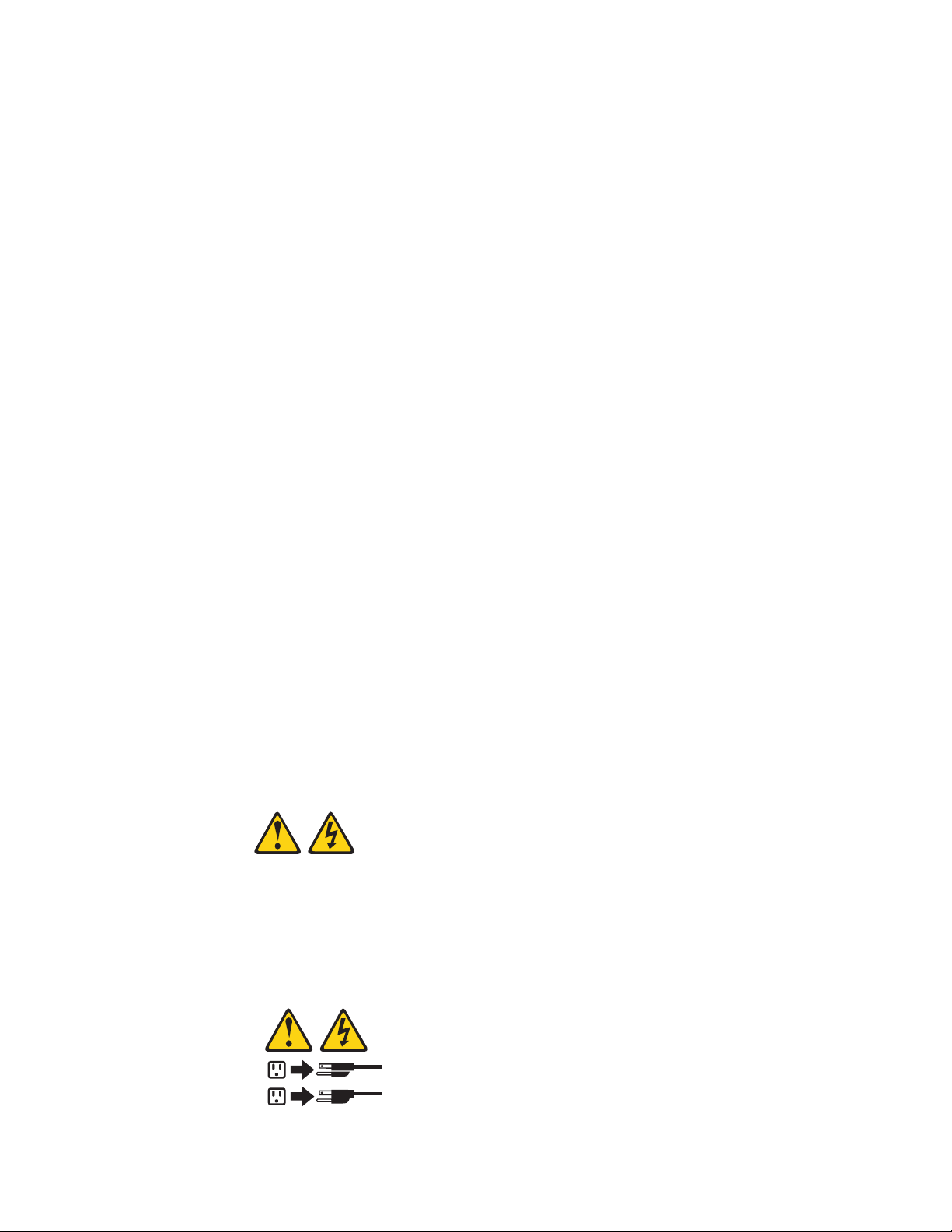
Statement 5:
CAUTION:
The power control button on the device and the power switch on the power
supply do not turn off the electrical current supplied to the device. The device
also might have more than one power cord. To remove all electrical current
from the device, ensure that all power cords are disconnected from the power
source.
2
1
12 ThinkServer RD120 Types 6444, 6445, 6446, and 6447: User Guide
Page 27

Attention: In a dc power environment, only trained service personnel other than
Lenovo service technicians are authorized to connect or disconnect power to the dc
power supply. See the documentation that comes with each dc power supply.
The server can be turned off in any of the following ways:
v You can turn off the server from the operating system, if your operating system
supports this feature. After an orderly shutdown of the operating system, the
server will be turned off automatically.
v You can press the power-control button to start an orderly shutdown of the
operating system and turn off the server, if your operating system supports this
feature.
v If the operating system stops functioning, you can press and hold the
power-control button for more than 4 seconds to turn off the server.
v The service processor can turn off the server as an automatic response to a
critical system failure.
v You can turn off the server through a request from the service processor.
Chapter 1. The ThinkServer RD120 server 13
Page 28

14 ThinkServer RD120 Types 6444, 6445, 6446, and 6447: User Guide
Page 29

Chapter 2. Installing optional devices
This chapter provides detailed instructions for installing optional hardware devices in
the server.
Server components
The following illustrations show the major components in the server. The
illustrations in this document might differ slightly from your hardware.
© Lenovo 2008, 2009. Portions © IBM Corp. 2008. 15
Page 30
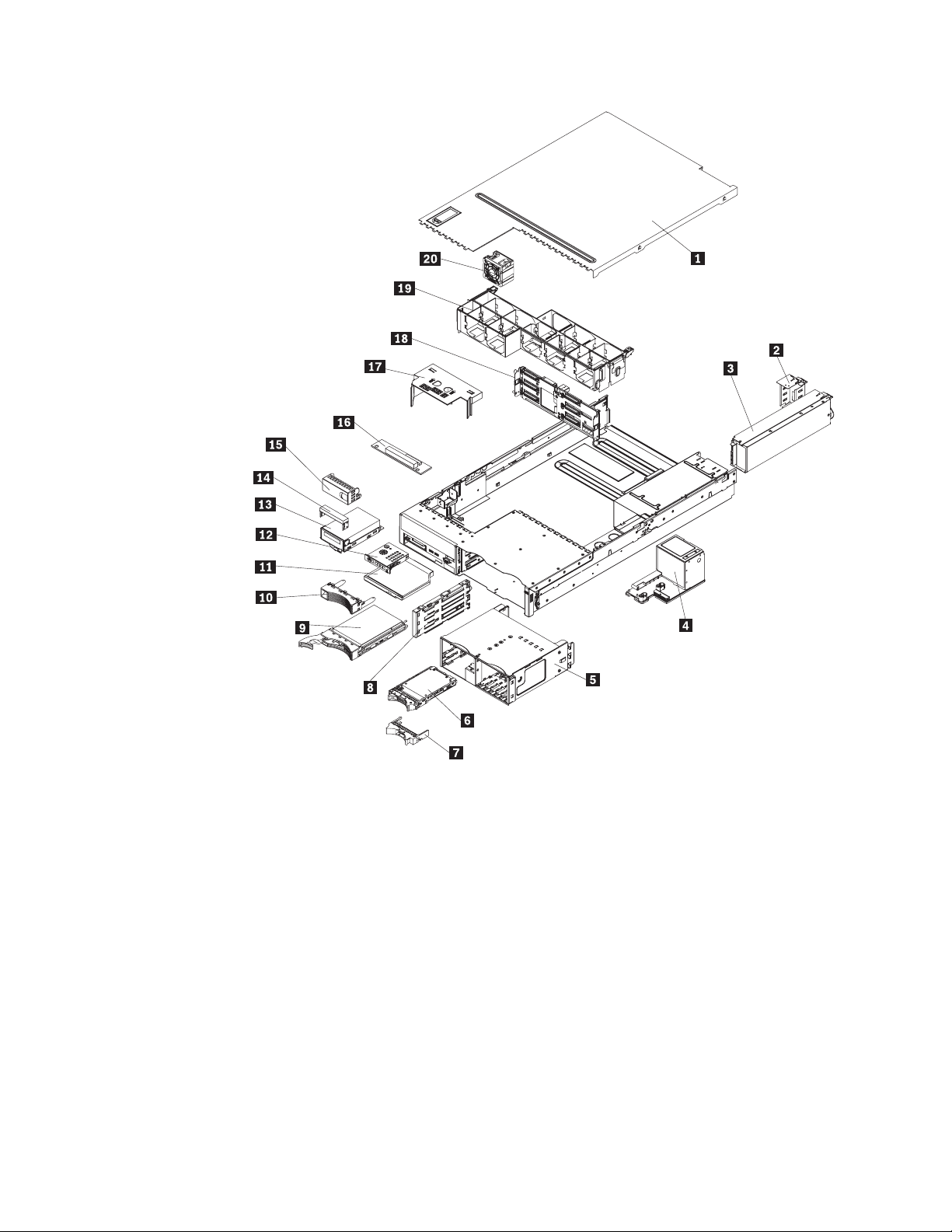
1 Cover 11 CD/DVD drive
2 Power-supply filler 12 Operator information panel
3 Power supply 13 Optional tape drive
4 Power backplane 14 Tape drive space filler
5 2.5-inch drive cage with hard disk
drive backplane
6 2.5-inch hard disk drive 16 CD/DVD media backplane
7 2.5-inch filler panel 17 Microprocessor air baffle
8 3.5-inch cage divider 18 3.5-inch hard disk drive backplane
9 3.5-inch hard disk drive 19 Fan bracket assembly
10 3.5-inch filler panel 20 Fans (5 or 10)
16 ThinkServer RD120 Types 6444, 6445, 6446, and 6447: User Guide
15 Tape drive filler
Page 31

1 Riser-card assembly 8 VRM
2 Full-height adapter 9 Microprocessor
3 DIMM air baffle 10 Heat sink
4 DIMM 11 Heat-sink filler
5 RAID SAS controller 12 Remote Supervisor Adapter II
SlimLine
6 System board 13 Low-profile adapter
7 Heat-sink retention module
Chapter 2. Installing optional devices 17
Page 32

System-board optional-device connectors
The following illustration shows the connectors on the system board for
user-installable optional devices.
1 PCI Express slots 3 and 4 6 Fan connectors
2 Systems-management Ethernet
connector
3 PCI riser card connector 8 Microprocessor connectors (1 and 2)
4 RAID SAS connector 9 Battery connector
5 DIMM connectors (1-9)
Note: The connectors for fans 7 and 10 are on the power backplane. See
“Power-backplane-board connectors” on page 19.
18 ThinkServer RD120 Types 6444, 6445, 6446, and 6447: User Guide
7 Voltage regulator module connector
Page 33

PCI riser-card adapter connectors
The following illustration shows the connectors 1 on the PCI riser card for
user-installable PCI adapters.
Note: For clarity, in the following illustration the PCI riser-card assembly is inverted.
Power-backplane-board connectors
The following illustration shows the internal connectors on the power-backplane
board.
1 Fan 10 connector
2 Hard disk drive power connector
3 Fan 7 connector
4 System board connector
Chapter 2. Installing optional devices 19
Page 34

System-board internal cable connectors
The following illustration shows the internal connectors on the system board.
1 Hard disk drive backplane signal
(J92)
2 Power backplane (J72) 8 CD/DVD power (J12)
3 Tape drive power (J100) 9 Operator information panel (J50)
4 Front USB (J80) 10 SATA tape drive signal (J102)
5 Front video (J51) 11 Intelligent Platform Management Bus
6 Internal USB (J82)
20 ThinkServer RD120 Types 6444, 6445, 6446, and 6447: User Guide
7 CD/DVD signal (J37)
(IPMB) connector
Page 35

System-board external connectors
The following illustration shows the external input/output connectors on the system
board.
1 Ethernet connectors 1 and 2 and USB
4 Serial connector
connectors 3 and 4
2 USB connectors 1 and 2 5 Systems-management Ethernet
connector
3 Video connector 6 SAS connector
Chapter 2. Installing optional devices 21
Page 36

System-board switches and jumpers
The following illustration shows the switches and jumpers on the system board.
Any switches or jumpers on the system board that are not shown in the illustration
are reserved. See the section about recovering the basic input/output system
(BIOS) code in the Hardware Maintenance Manual on the ThinkServer
Documentation DVD for information about using the boot block recovery jumper.
1 Boot block recovery jumper (J42)
2 Switch block (SW2)
Table 2 on page 23 describes the function of each switch on the switch block.
22 ThinkServer RD120 Types 6444, 6445, 6446, and 6447: User Guide
Page 37

Table 2. Switches 1 - 8
Switch
number Default value
Switch
description
8 Off Reserved.
7 Off Reserved.
6 Off Reserved.
5 Off Power-on password override. Changing the position of this switch bypasses the
power-on password check the next time the server is turned on and starts the
Configuration/Setup Utility program so that you can change or delete the power-on
password. You do not have to move the switch back to the default position after the
password is overridden.
Changing the position of this switch does not affect the administrator password check
if an administrator password is set.
See “Passwords” on page 84 for additional information about the power-on password.
4 Off Reserved.
3 Off Reserved.
2 Off Reserved.
1 Off Clear CMOS. When this switch is toggled to On, it clears the CMOS data, which
clears the power-on password.
Important:
1. Before you change any switch settings or move any jumpers, turn off the server;
then, disconnect all power cords and external cables. (Review the information in
“Safety” on page v, “Installation guidelines” on page 29, “Handling
static-sensitive devices” on page 31, and “Turning off the server” on page 12.)
Attention: In a dc power environment, only trained service personnel other
than Lenovo service technicians are authorized to connect or disconnect power
to the dc power supply. See the documentation that comes with each dc power
supply.
2. Any system-board switch or jumper blocks that are not shown in the illustrations
in this document are reserved.
Chapter 2. Installing optional devices 23
Page 38

System-board LEDs
The following illustration shows the light-emitting diodes (LEDs) on the system
board.
1 Riser-card-missing error LED 6 VRM error LED
2 RAID error LED 7 Microprocessors 1 and 2 error LEDs
3 DIMMs 1 - 12 error LEDs 8 PCI slots 3 and 4 error LEDs
4 BMC heartbeat LED 9 System-management Ethernet error
5 Power Channels A, B, C, D error
LEDs
24 ThinkServer RD120 Types 6444, 6445, 6446, and 6447: User Guide
LED
10 3-V battery error LED
Page 39

Riser-card assembly LEDs
The following illustration shows the light-emitting diodes (LEDs) on the riser-card
assembly.
1 PCI slot 1 error LED
2 PCI slot 2 error LED
Chapter 2. Installing optional devices 25
Page 40

Diagnostics panel
The following illustration shows the controls and LEDs on the diagnostics panel.
Light Path
Diagnostics
OVER SPEC
REMIND
CPU
MEM
FAN
PCI
PS1SPPS2
VRM
CNFG
NMI
S ERR
DASD
RAID
TEMP
BRD
To access the diagnostics panel, slide the release latch on the front of the operator
information panel to the left.
The following table lists the LEDs on the diagnostics panel and suggested actions
to solve the detected problems.
v Follow the suggested actions in the order in which they are listed in the Action column until the problem
is solved.
v See the parts listing in the Hardware Maintenance Manual to determine which components are customer
replaceable units (CRU) and which components are field replaceable units (FRU).
v If an action step is preceded by “(Trained service technician only),” that step must be performed only by a
trained service technician.
LED Description Action
None, but
the
systemerror LED
is lit.
OVER
SPEC
An error has occurred and cannot be
diagnosed, or the Advanced System
Management (ASM) processor on the
Remote Supervisor Adapter II SlimLine
has failed. The error is not represented
by a diagnostics LED.
The power supplies are using more
power than their maximum rating.
Check the system-error log for information about the error.
1. Remove optional devices from the server.
2. Replace the failing power supply.
Attention: In a dc power environment, only trained
service personnel other than Lenovo service technicians are
authorized to connect or disconnect power to the dc power
supply and to remove and install a dc power supply. See
the documentation that comes with each dc power supply.
PS 1 The power supply in bay 1 has failed. Attention: In a dc power environment, only trained service
personnel other than Lenovo service technicians are authorized
to connect or disconnect power to the dc power supply and to
remove and install a dc power supply. See the documentation
that comes with each dc power supply.
1. Make sure that the power supply is correctly seated.
2. Replace the failed power supply.
26 ThinkServer RD120 Types 6444, 6445, 6446, and 6447: User Guide
Page 41

v Follow the suggested actions in the order in which they are listed in the Action column until the problem
is solved.
v See the parts listing in the Hardware Maintenance Manual to determine which components are customer
replaceable units (CRU) and which components are field replaceable units (FRU).
v If an action step is preceded by “(Trained service technician only),” that step must be performed only by a
trained service technician.
LED Description Action
PS 2 The power supply in bay 2 has failed. Attention: In a dc power environment, only trained service
personnel other than Lenovo service technicians are authorized
to connect or disconnect power to the dc power supply and to
remove and install a dc power supply. See the documentation
that comes with each dc power supply.
1. Make sure that the power supply is correctly seated.
2. Replace the failed power supply.
CPU A microprocessor has failed.
1. Make sure that the failing microprocessor, which is indicated
by a lit LED on the system board, is installed correctly. See
“Installing a microprocessor” on page 54 for information
about installing a microprocessor.
2. Make sure that a ServeRAID 8k or 8k-l SAS controller is
installed and correctly seated. Make sure that the battery for
the ServeRAID 8k SAS controller is installed correctly.
3. Call for service.
VRM An error occurred on the
microprocessor voltage regulator
module (VRM).
CNFG A hardware configuration error has
occurred.
1. Replace the VRM.
2. Call for service.
1. Check the microprocessors that were just installed to make
sure that they are compatible with each other and with the
VRM (see “Installing a microprocessor” on page 54 for
compatiblity requirements).
2. (Trained service technician only) Replace an incompatible
microprocessor.
3. Check the system-error logs for information about the error.
Replace any components that are indicated.
MEM A memory error has occurred. Replace the failing DIMM, which is indicated by the lit LED on
the system board.
NMI A machine check error has occurred. Check the system-error log for information about the error.
S ERR Reserved.
SP The service processor has failed. Attention: In a dc power environment, only trained service
personnel other than Lenovo service technicians are authorized
to connect or disconnect power to the dc power supply. See the
documentation that comes with each dc power supply.
1. Remove power from the server; then, reconnect the server
to power and restart the server.
2. Update the firmware on the BMC.
3. Call for service
DASD A hard disk drive error has occurred.
1. Check the LEDs on the hard disk drives and replace the
indicated drive.
2. Call for service.
Chapter 2. Installing optional devices 27
Page 42

v Follow the suggested actions in the order in which they are listed in the Action column until the problem
is solved.
v See the parts listing in the Hardware Maintenance Manual to determine which components are customer
replaceable units (CRU) and which components are field replaceable units (FRU).
v If an action step is preceded by “(Trained service technician only),” that step must be performed only by a
trained service technician.
LED Description Action
RAID A RAID controller error has occurred.
1. Make sure that a RAID controller is installed.
Note: The server will not start without a RAID controller
installed.
2. Check the system-error log for information about the error.
FAN A fan has failed, is operating too slowly,
or has been removed. The TEMP LED
Replace the failing fan, which is indicated by a lit LED on the
fan itself.
might also be lit.
TEMP The system temperature has exceeded
a threshold level. A failing fan can
cause the TEMP LED to be lit.
1. Determine whether a fan has failed. If it has, replace it.
2. Make sure that the room temperature is not too high. See
“Features and specifications” on page 3 for temperature
information.
3. Make sure that the air vents are not blocked.
4. Call for service.
BRD An error has occurred on the system
board.
1. Check the LEDs on the system board to identify the
component that is causing the error.
2. Check the system-error log for information about the error.
PCI An error has occurred on a PCI bus or
on the system board. An additional LED
will be lit next to a failing PCI slot.
1. Check the LEDs on the PCI slots to identify the component
that is causing the error.
2. Check the system-error log for information about the error.
3. If you cannot isolate the failing adapter through the LEDs
and the information in the system-error log, remove one
adapter at a time from the failing PCI bus, and restart the
server after each adapter is removed.
4. Call for service.
For more information about diagnostics, see the Hardware Maintenance Manual on
the ThinkServer Documentation DVD.
28 ThinkServer RD120 Types 6444, 6445, 6446, and 6447: User Guide
Page 43

Installation guidelines
Before you install optional devices, read the following information:
v Read the safety information that begins on page v and the guidelines in
“Handling static-sensitive devices” on page 31. This information will help you
work safely.
v When you install your new server, take the opportunity to download and apply
the most recent firmware updates. This step will help to ensure that any known
issues are addressed and that your server is ready to function at maximum levels
of performance. Or, to download updates from the Lenovo Support Web site,
complete the following steps:
1. Go to: http://www.lenovo.com/support.
2. Enter your product number (machine type and model number) or select
Servers and Storage from the Select your product list.
3. From Family list, select ThinkServer RD120, and click Continue.
4. Click Downloads and drivers to download firmware updates.
Before you install optional hardware, make sure that the server is working
v
correctly. Start the server, and make sure that the operating system starts, if an
operating system is installed, or that a 19990305 error code is displayed,
indicating that an operating system was not found but the server is otherwise
working correctly. If the server is not working correctly, see “Solving problems” in
the Installation Guide on the ThinkServer Documentation DVD for diagnostic
information.
v Observe good housekeeping in the area where you are working. Place removed
covers and other parts in a safe place.
v If you must start the server while the cover is removed, make sure that no one is
near the server and that no tools or other objects have been left inside the
server.
v Do not attempt to lift an object that you think is too heavy for you. If you have to
lift a heavy object, observe the following precautions:
– Make sure that you can stand safely without slipping.
– Distribute the weight of the object equally between your feet.
– Use a slow lifting force. Never move suddenly or twist when you lift a heavy
object.
– To avoid straining the muscles in your back, lift by standing or by pushing up
with your leg muscles.
v Make sure that you have an adequate number of properly grounded electrical
outlets for the server, monitor, and other devices.
v Back up all important data before you make changes to disk drives.
v Have a small flat-blade screwdriver available.
v You do not have to turn off the server to install or replace hot-swap fans,
redundant hot-swap ac power supplies, or hot-plug Universal Serial Bus (USB)
devices. However, you must turn off the server before performing any steps that
involve removing or installing adapter cables or non-hot-swap optional devices or
components.
Attention: In a dc power environment, only trained service personnel other
than Lenovo service technicians are authorized to connect or disconnect power
to the dc power supply and to install and remove a dc power supply. See the
documentation that comes with each dc power supply.
v Blue on a component indicates touch points, where you can grip the component
to remove it from or install it in the server, open or close a latch, and so on.
Chapter 2. Installing optional devices 29
Page 44

v Orange on a component or an orange label on or near a component indicates
that the component can be hot-swapped, which means that if the server and
operating system support hot-swap capability, you can remove or install the
component while the server is running. (Orange can also indicate touch points on
hot-swap components.) See the instructions for removing or installing a specific
hot-swap component for any additional procedures that you might have to
perform before you remove or install the component.
v When you are finished working on the server, reinstall all safety shields, guards,
labels, and ground wires.
v For a list of Lenovo optional devices for the server, see http://www/.lenovo.com/
thinkserver.
System reliability guidelines
To help ensure proper system cooling and system reliability, make sure that the
following requirements are met:
v Each of the drive bays has a drive or a filler panel and electromagnetic
compatibility (EMC) shield installed in it.
v If the server has redundant power, each of the power-supply bays has a power
supply installed in it.
Attention: In a dc power environment, only trained service personnel other
than Lenovo service technicians are authorized to connect or disconnect power
to the dc power supply and to install and remove a dc power supply. See the
documentation that comes with each dc power supply.
v There is adequate space around the server to allow the server cooling system to
work properly. Leave approximately 50 mm (2.0 in.) of open space around the
front and rear of the server. Do not place objects in front of the fans. For proper
cooling and airflow, replace the server cover before you turn on the server.
Operating the server for extended periods of time (more than 30 minutes) with
the server cover removed might damage server components.
v You have followed the cabling instructions that come with optional adapters.
v You have replaced a failed fan within 48 hours.
v You have replaced a hot-swap drive within 2 minutes of removal.
v You do not operate the server without the air baffles installed. Operating the
server without the air baffles might cause the microprocessors to overheat.
v Microprocessor socket 2 always contains either a heat-sink filler or a
microprocessor and heat sink.
Working inside the server with the power on
Attention: Static electricity that is released to internal server components when
the server is powered-on might cause the server to halt, which could result in the
loss of data. To avoid this potential problem, always use an electrostatic-discharge
wrist strap or other grounding system when working inside the server with the
power on.
The server supports hot-plug, hot-add, and hot-swap devices and is designed to
operate safely while it is turned on and the cover is removed. Follow these
guidelines when you work inside a server that is turned on:
v Avoid wearing loose-fitting clothing on your forearms. Button long-sleeved shirts
before working inside the server; do not wear cuff links while you are working
inside the server.
v Do not allow your necktie or scarf to hang inside the server.
30 ThinkServer RD120 Types 6444, 6445, 6446, and 6447: User Guide
Page 45

v Remove jewelry, such as bracelets, necklaces, rings, and loose-fitting wrist
watches.
v Remove items from your shirt pocket, such as pens and pencils, that could fall
into the server as you lean over it.
v Avoid dropping any metallic objects, such as paper clips, hairpins, and screws,
into the server.
Handling static-sensitive devices
Attention: Static electricity can damage the server and other electronic devices.
To avoid damage, keep static-sensitive devices in their static-protective packages
until you are ready to install them.
To reduce the possibility of damage from electrostatic discharge, observe the
following precautions:
v Limit your movement. Movement can cause static electricity to build up around
you.
v The use of a grounding system is recommended. For example, wear an
electrostatic-discharge wrist strap, if one is available. Always use an
electrostatic-discharge wrist strap or other grounding system when working inside
the server with the power on.
v Handle the device carefully, holding it by its edges or its frame.
v Do not touch solder joints, pins, or exposed circuitry.
v Do not leave the device where others can handle and damage it.
v While the device is still in its static-protective package, touch it to an unpainted
metal surface on the outside of the server for at least 2 seconds. This drains
static electricity from the package and from your body.
v Remove the device from its package and install it directly into the server without
setting down the device. If it is necessary to set down the device, put it back into
its static-protective package. Do not place the device on the server cover or on a
metal surface.
v Take additional care when handling devices during cold weather. Heating reduces
indoor humidity and increases static electricity.
Removing the cover
Important: Before you install optional hardware, make sure that the server is
working correctly. Start the server, and make sure that the operating system starts,
if an operating system is installed, or that a 19990305 error code is displayed,
indicating that an operating system was not found but the server is otherwise
working correctly. If the server is not working correctly, see the Hardware
Maintenance Manual for diagnostic information.
To remove the cover, complete the following steps:
1. Read the safety information that begins on page v and “Installation guidelines”
on page 29.
2. If you are planning to install or remove a microprocessor, memory module, PCI
adapter, battery, or other non-hot-swap optional device, turn off the server and
all attached devices and disconnect all external cables and power cords (see
“Turning off the server” on page 12).
Chapter 2. Installing optional devices 31
Page 46

Attention: In a dc power environment, only trained service personnel other
than Lenovo service technicians are authorized to connect or disconnect power
to the dc power supply. See the documentation that comes with each dc power
supply.
3. Press down on the left and right side latches and pull the server out of the rack
enclosure until both slide rails lock.
Note: You can reach the cables on the back of the server when the server is in
the locked position.
4.
Lift the cover-release latch 1. Lift the cover off the server and set the cover
aside.
Attention: For proper cooling and airflow, replace the cover before you turn on
the server. Operating the server for extended periods of time (over 30 minutes) with
the cover removed might damage server components.
Removing the riser-card assembly
The server comes with one riser-card assembly that contains two PCI Express x8
connectors. Yo u can replace the PCI Express riser-card assembly with a PCI-X
riser-card assembly, which contains two PCI-X 64-bit 133 MHz connectors. The
PCI-X connectors support single-width IXA adapters. See http://www.lenovo.com/
thinkserver/ for a list of riser-card assemblies that you can use with the server.
32 ThinkServer RD120 Types 6444, 6445, 6446, and 6447: User Guide
Page 47

1 Access holes
2 Release tabs
To remove the riser-card assembly, complete the following steps:
1. Read the safety information that begins on page v and “Installation guidelines”
on page 29.
2. Turn off the server and peripheral devices, and disconnect the power cord and
all external cables.
Attention: In a dc power environment, only trained service personnel other
than Lenovo service technicians are authorized to connect or disconnect power
to the dc power supply. See the documentation that comes with each dc power
supply.
3. Remove the cover (see “Removing the cover” on page 31).
4. Push the two riser-card-assembly release tabs toward the low-profile PCI slots;
then, grasp the assembly at the rear and side edges and lift it to remove it from
the server. Place the riser-card assembly on a flat, static-protective surface.
Chapter 2. Installing optional devices 33
Page 48

Installing the riser-card assembly
To install the riser-card assembly, complete the following steps.
1 Access holes
2 Guide
3 Release tabs
4 Guide
1. Read the safety information that begins on page v and “Installation guidelines”
on page 29.
2. Make sure that the server and all peripheral devices are turned off and that the
power cords and all external cables are disconnected.
Attention: In a dc power environment, only trained service personnel other
than Lenovo service technicians are authorized to connect or disconnect power
to the dc power supply. See the documentation that comes with each dc power
supply.
3. Reinstall any adapters and reconnect any internal cables that you removed in
other procedures.
4. Carefully align the riser-card assembly with the release tab posts, the guides on
the rear of the server, and the riser-card connector on the system board; then,
press down on the assembly. Make sure that the riser-card assembly is fully
seated in the riser-card connector on the system board.
If you have other optional devices to install, do so now. Otherwise, go to
“Completing the installation” on page 74.
Removing the microprocessor air baffle
When you work with some optional devices, you must first remove the
microprocessor air baffle to access certain components or connectors on the
system board. The following illustration shows how to remove the microprocessor
air baffle.
34 ThinkServer RD120 Types 6444, 6445, 6446, and 6447: User Guide
Page 49

1 Microprocessor air baffle
2 Finger holes
To remove the microprocessor air baffle, complete the following steps:
1. Read the safety information that begins on page v and “Installation guidelines”
on page 29.
2. Turn off the server and peripheral devices and disconnect all power cords and
external cables (see “Turning off the server” on page 12).
Attention: In a dc power environment, only trained service personnel other
than Lenovo service technicians are authorized to connect or disconnect power
to the dc power supply. See the documentation that comes with each dc power
supply.
3. Remove the cover (see “Removing the cover” on page 31).
4. Place your fingers into the two finger holes on the top of the air baffle and lift
the air baffle out of the server.
Attention: For proper cooling and airflow, replace the air baffle before you
turn on the server. Operating the server with an air baffle removed might
damage server components.
Chapter 2. Installing optional devices 35
Page 50

Installing the microprocessor air baffle
1 Microprocessor air baffle
2 Finger holes
To install the microprocessor air baffle, complete the following steps:
1. Read the safety information that begins on page v and “Installation guidelines”
on page 29.
2. Make sure that the server and peripheral devices are turned off (see “Turning
off the server” on page 12) and that all power cords and external cables are
disconnected.
Attention: In a dc power environment, only trained service personnel other
than Lenovo service technicians are authorized to connect or disconnect power
to the dc power supply. See the documentation that comes with each dc power
supply.
3. Remove the cover (see “Removing the cover” on page 31).
4. Place your fingers into the two finger holes on the top of the air baffle.
5. Align the tab on the left side of the air baffle with the slot in the left side of the
chassis.
6. Lower the air baffle into the server.
Attention: For proper cooling and airflow, replace the air baffle before you
turn on the server. Operating the server with an air baffle removed might
damage server components.
36 ThinkServer RD120 Types 6444, 6445, 6446, and 6447: User Guide
Page 51

Removing the DIMM air baffle
When you work with some optional devices, you must first remove the DIMM air
baffle to access certain components or connectors on the system board. The
following illustration shows how to remove the DIMM air baffle.
1 DIMM air baffle
2 Riser card assembly
3 Finger hole
4 Release ring
To remove the DIMM air baffle, complete the following steps:
1. Read the safety information that begins on page v and “Installation guidelines”
on page 29.
2. Turn off the server and peripheral devices and disconnect all power cords and
external cables (see “Turning off the server” on page 12).
Attention: In a dc power environment, only trained service personnel other
than Lenovo service technicians are authorized to connect or disconnect power
to the dc power supply. See the documentation that comes with each dc power
supply.
3. Remove the cover (see “Removing the cover” on page 31).
4. Remove the riser-card assembly (see “Removing the riser-card assembly” on
page 32).
5. Place your fingers into the handle 4 and finger hole on the top of the air
baffle.
Chapter 2. Installing optional devices 37
Page 52

6. Press the handle 4 toward the finger hole and lift the air baffle out of the
server.
Attention: For proper cooling and airflow, replace the air baffle before you
turn on the server. Operating the server with an air baffle removed might
damage server components.
Installing the DIMM air baffle
The following illustration shows how to install the DIMM air baffle.
1 DIMM air baffle
2 Riser card assembly
3 Finger hole
4 Release ring
To install the DIMM air baffle, complete the following steps:
1. Read the safety information that begins on page v and “Installation guidelines”
on page 29.
2. Make sure that the server and peripheral devices are turned off (see “Turning
off the server” on page 12) and that all power cords and external cables are
disconnected.
Attention: In a dc power environment, only trained service personnel other
than Lenovo service technicians are authorized to connect or disconnect power
to the dc power supply. See the documentation that comes with each dc power
supply.
3. Remove the cover (see “Removing the cover” on page 31).
38 ThinkServer RD120 Types 6444, 6445, 6446, and 6447: User Guide
Page 53

4. Align the tabs on the sides of the air baffle with the slots on the power-supply
cage.
5. Place your fingers into the handle 4 and finger hole on the top of the DIMM
air baffle.
6. Press the handle 4 toward the finger hole and lower the air baffle so that the
lip on the right side of the baffle covers the lip on the side of the power-supply
cage.
7. Press the DIMM air baffle into place.
Attention: For proper cooling and airflow, replace the air baffle before you turn on
the server. Operating the server with an air baffle removed might damage server
components.
Installing an adapter
1 Expansion slot covers 5 Low profile PCI Express adapter
2 Riser-card assembly 6 Expansion slot cover
3 Expansion slot 1 7 Expansion slot 2
4 Adapter 8 Adapter
Chapter 2. Installing optional devices 39
Page 54

1 PCI slot 1
2 PCI slot 2
3 PCI slot 3
4 PCI slot 4
The following notes describe the types of adapters that the server supports and
other information that you must consider when installing an adapter:
v You can install only low-profile adapters in PCI slots 3 and 4 on the system
board.
v You can install a full-height, half-length adapter in slot 2 on the PCI riser card
and a full-height, full-length adapter in slot 1 on the PCI riser card.
v An optional Remote Supervisor Adapter II SlimLine can be installed only in a
dedicated slot on the system board.
v The server supports only 3.3 V and universal PCI adapters.
v The PCI bus configuration is as follows:
– Non-hot-plug, low-profile PCI Express x8 (x4 lanes), slot 4
– Non-hot-plug, low-profile PCI Express x8 (x4 lanes), slot 3
– Non-hot-plug, half-length PCI Express x8 (x8 lanes), slot 2
– Non-hot-plug, full-length PCI Express x8 (x8 lanes), slot 1
The system scans devices in the following order, if you have not changed the
v
default boot order: integrated Ethernet controllers, integrated SAS controller, and
then PCI slots 1, 2, 3, and 4.
riser card
PCI
The following illustration shows the location of the adapter expansion slots 1 on
the PCI riser card.
Note: For clarity, the riser-card assembly is inverted in the illustration.
To install an adapter, complete the following steps:
40 ThinkServer RD120 Types 6444, 6445, 6446, and 6447: User Guide
Page 55

1. Read the safety information that begins on page v and “Installation guidelines”
on page 29.
2. Turn off the server and peripheral devices and disconnect all power cords and
external cables (see “Turning off the server” on page 12).
Attention: In a dc power environment, only trained service personnel other
than Lenovo service technicians are authorized to connect or disconnect power
to the dc power supply. See the documentation that comes with each dc power
supply.
3. Remove the cover (see “Removing the cover” on page 31).
4. Determine which expansion slot you will use for the adapter.
5. If you are installing an adapter in PCI slot 1 or 2, remove the PCI riser-card
assembly (see “Removing the riser-card assembly” on page 32).
1 Access holes
2 Release tabs
6. Slide the expansion-slot cover out of the PCI low-profile expansion slot or PCI
riser-card assembly expansion slot.
7. Install the adapter. The following illustration shows how to install an adapter in
a PCI slot.
Note: For clarity, the riser-card assembly 1 is shown inverted in the
following illustration.
Chapter 2. Installing optional devices 41
Page 56

8. If you removed the PCI riser-card assembly to install the adapter, align the
riser-card assembly with the release-tab posts, rear guides, and connector;
then, press the PCI riser-card assembly firmly into the connector (see
“Installing the riser-card assembly” on page 34).
1 Access holes
2 Guide
3 Release tabs
4 Guide
9. Connect any required cables to the adapter.
Attention:
v When you route cables, do not block any connectors or the ventilated space
around any of the fans.
v Make sure that cables are not routed on top of components under the PCI
riser-card assembly.
v Make sure that cables are not pinched by the server components.
Perform any configuration tasks that are required for the adapter.
10.
42 ThinkServer RD120 Types 6444, 6445, 6446, and 6447: User Guide
Page 57

If you have other optional devices to install or remove, do so now. Otherwise, go to
“Completing the installation” on page 74.
Removing an adapter
To remove an adapter, complete the following steps.
1 Expansion slot cover 5 Low-profile PCI Express adapter
2 Raiser-card assembly 6 Expansion slot cover
3 Expansion slot 1 7 Expansion slot 2
4 Adapter 8 Adapter
1. Read the safety information that begins on page v and “Installation guidelines”
on page 29.
2. Turn off the server and peripheral devices and disconnect all power cords and
external cables (see “Turning off the server” on page 12).
Attention: In a dc power environment, only trained service personnel other
than Lenovo service technicians are authorized to connect or disconnect power
to the dc power supply. See the documentation that comes with each dc power
supply.
3. Remove the cover (see “Removing the cover” on page 31).
4. Pull the server out of the rack; then, remove the cover (see “Removing the
cover” on page 31).
Chapter 2. Installing optional devices 43
Page 58

5. If the adapter is on the riser card, remove the riser-card assembly from the
server (see “Removing the riser-card assembly” on page 32).
1 Access holes
2 Release tabs
6. Disconnect any cables from the adapter.
7. Carefully grasp the adapter by its top edge or upper corners, and pull the
adapter from the PCI slot.
8. If you have other optional devices to install or remove, do so now. Otherwise,
go to “Completing the installation” on page 74.
44 ThinkServer RD120 Types 6444, 6445, 6446, and 6447: User Guide
Page 59

Replacing the RAID SAS controller
A ServeRAID SAS controller can be installed only in a dedicated slot on the system
board. The server comes with a ServeRAID-8k-l SAS Controller installed.
Note: The ServeRAID-8k-l SAS Controller does not have a battery.
To replace the ServeRAID-8k-l SAS Controller with a ServeRAID-8k SAS Controller,
complete the following steps:
1. Read the safety information that begins on page v and “Installation guidelines”
on page 29.
2. Turn off the server and peripheral devices and disconnect all power cords and
external cables (see “Turning off the server” on page 12).
Attention: In a dc power environment, only trained service personnel other
than Lenovo service technicians are authorized to connect or disconnect power
to the dc power supply. See the documentation that comes with each dc power
supply.
3. Remove the cover (see “Removing the cover” on page 31).
4. Remove the riser-card assembly and the air baffle over the DIMMs (see
“Removing the DIMM air baffle” on page 37).
5. Locate the ServeRAID-8k-l SAS controller on the system board (see
“System-board optional-device connectors” on page 18).
Attention: To avoid breaking the retaining clips or damaging the connectors,
handle the clips gently.
6. Open the retaining clip on each end of the connector.
7. Lift the ServeRAID-8k-l SAS controller out of the connector.
8. Touch the static-protective package that contains the new ServeRAID-8k SAS
controller to any unpainted metal surface on the server. Then, remove the
ServeRAID-8k SAS controller from the package.
Chapter 2. Installing optional devices 45
Page 60

1 RAID controller 4 Battery mounting tabs
2 Battery cable 5 Battery mounting clips
3 Battery 6 Battery cable connector
9. Turn the new ServeRAID-8k SAS controller so that the keys on the bottom
edge align correctly with the connector.
10. Firmly press the ServeRAID-8k SAS controller straight down into the connector
by applying pressure on both ends of the controller simultaneously. The
retaining clips snap into the locked position when the controller is firmly seated
in the connector.
Note: If there is a gap between the controller and the retaining clips, the
controller has not been correctly installed. In this case, open the retaining clips
and remove the controller; then, reinsert the controller.
11. Remove the battery from the ServeRAID-8k SAS Controller package.
12. Slide the battery mounting tabs into the battery mounting clips on the server
wall that is next to the ServeRAID SAS controller connector.
13. Connect the battery to the ServeRAID-8k SAS Controller.
14. Replace the air baffle over the DIMMs (see “Installing the DIMM air baffle” on
page 38).
15. Replace the riser-card assembly (see “Installing the riser-card assembly” on
page 34).
you have other optional devices to install or remove, do so now. Otherwise, go to
If
“Completing the installation” on page 74.
Notes:
1. When you restart the server for the first time after you install a ServeRAID-8k
SAS controller, the monitor screen remains blank while the controller initializes
46 ThinkServer RD120 Types 6444, 6445, 6446, and 6447: User Guide
Page 61

the battery. This might take a few minutes, after which the startup process
continues. This is a one-time occurrence.
Important: Yo u must allow the initialization process to be completed. If you do
not, the battery will not work, and the server might not start.
The battery comes partially charged, at 30% or less of capacity. Run the server
for 4 to 6 hours to fully charge the controller battery. The LED just above the
battery on the controller remains lit until the battery is fully charged.
Until the battery is fully charged, the controller firmware sets the controller
cache to write-through mode; after the battery is fully charged, the controller
firmware re-enables write-back mode.
2. When you restart the server, you will be given the opportunity to import the
existing RAID configuration to the new ServeRAID-8k SAS Controller.
Installing a hard disk drive
Locate the documentation that comes with the hard disk drive and follow those
instructions in addition to the instructions in this chapter.
Important: Do not install a SCSI hard disk drive in this server; install only SAS hard
disk drives.
The following notes describe the type of hard disk drive that the server supports
and other information that you must consider when installing a hard disk drive:
v The server 3.5-inch models support six slim 3.5-inch hard disk drives installed on
Ultra-Slim hard disk drive trays for 3.5-inch drives. For a list of supported 3.5-inch
hard disk drives, see http://www.lenovo.com/thinkserver.
v The server 2.5-inch models support eight 2.5-inch hot-swap hard disk drives
installed on Ultra-Slim hard disk drive trays for 2.5-inch drives. For a list of
supported 2.5-inch hard disk drives, see http://www.lenovo.com/thinkserver.
v All hot-swap drives in the server should have the same throughput speed rating.
Mixing hard disk drives with different speed ratings will cause all drives to
operate at the lower throughput speed.
v The ID that is assigned to each bay is printed on the front of the server.
The following illustrations show how to install a hot-swap hard disk drive.
3.5-inch drives
1 Filler panel 3 Hard disk drive
2 Tray handle
Chapter 2. Installing optional devices 47
Page 62

2.5-inch drives
To install a drive in a hot-swap bay, complete the following steps.
Attention: To maintain proper system cooling, do not operate the server for more
than 10 minutes without either a drive or a filler panel installed in each bay.
1. Read the safety information that begins on page v and “Installation guidelines”
on page 29.
2. Remove the filler panel from one of the empty hot-swap bays.
v 3.5-inch models: Insert your finger into the depression at the left side of the
filler panel and pull it away from the server.
v 2.5-inch models: Grasp both sides of the front of the filler panel and pull it
away from the server.
Install the hard disk drive in the hot-swap bay:
3.
a. Make sure that the tray handle is open (that is, perpendicular to the drive).
b. Align the drive assembly with the guide rails in the bay.
c. Gently push the drive assembly into the bay until the drive stops.
d. Push the tray handle to the closed (locked) position.
e. Check the hard disk drive status LED to verify that the hard disk drive is
operating correctly.
If the amber hard disk drive status LED for a drive is lit continuously, that
drive is faulty and must be replaced. If the green hard disk drive activity LED
is flashing, the drive is being accessed.
You might have to reconfigure the disk arrays after you install hard disk
Note:
drives. See the RAID documentation on the IBM ServeRAID Support CD for
information about these RAID controllers.
you have other optional devices to install or remove, do so now. Otherwise, go to
If
“Completing the installation” on page 74.
48 ThinkServer RD120 Types 6444, 6445, 6446, and 6447: User Guide
Page 63

Removing a hard disk drive
3.5-inch drives
1 Tray handle
2 Hard disk drive
Chapter 2. Installing optional devices 49
Page 64

2.5-inch drives
To remove a hot-swap hard disk drive, complete the following steps:
1. Read the safety information that begins on page v and “Installation guidelines”
on page 29.
2. Move the tray handle on the drive to the open position (perpendicular to the
drive).
3. Pull the hot-swap drive assembly from the bay.
Note: You might have to reconfigure the disk arrays after you remove a hard
disk drive.
you have other optional devices to install or remove, do so now. Otherwise, go to
If
“Completing the installation” on page 74.
Installing an optional tape drive
Prepare the drive according to the instructions that come with the drive, setting any
switches or jumpers; then, see “Installing a SATA tape drive in a 3.5-inch model
server” or “Installing a SATA tape drive in a 2.5-inch model server” on page 53.
Installing a SATA tape drive in a 3.5-inch model server
Install the optional SATA tape drive in the two bottom-left hard disk drive bays. If
hard disk drives are installed in those bays, move the drives to other bays. The
cables for the tape drive come with the tape drive.
50 ThinkServer RD120 Types 6444, 6445, 6446, and 6447: User Guide
Page 65

To install a tape drive in a 3.5-inch model server, complete the following steps:
1. Read the safety information that begins on page v and “Installation guidelines”
on page 29.
2. Turn off the server and peripheral devices, and disconnect the power cords
and all external cables.
Attention: In a dc power environment, only trained service personnel other
than Lenovo service technicians are authorized to connect or disconnect power
to the dc power supply. See the documentation that comes with each dc power
supply.
3. Remove the server cover (see “Removing the cover” on page 31).
4. Remove the fan-bracket assembly (see “Removing the fan-bracket assembly”
on page 70).
5. Remove the filler panels from the two bottom-left hard disk drive bays.
6. If you have not attached the space filler from the tape enablement kit to the
tape-drive assembly, do so now.
7. From the inside of the server, thread the tape-drive end of the cables through
the slot in the left side of the hard disk drive cage and out the front of the
server.
8. Connect the cables to the back of the tape drive.
9. Push the tape-drive assembly into the bays, gently pulling the cables farther
into the server as you do so, until the tape-drive assembly stops.
10. Push the tray handle to the closed (locked) position.
11. Connect the cable connectors to the following system-board connectors (see
“System-board internal cable connectors” on page 20 for the location of the
connectors):
v Signal connector: SATA tape drive signal connector, J102
v Power connector: tape-drive power connector, J100
The following illustration shows the routing of the SATA tape drive signal cable.
Important: Make sure that the cables avoid any fan connectors.
Chapter 2. Installing optional devices 51
Page 66

1 S ATA tape cable connector
2 S ATA tape cable
12. Install the fan-bracket assembly (see “Installing the fan-bracket assembly” on
page 72).
you have other optional devices to install or remove, do so now. Otherwise, go to
If
“Completing the installation” on page 74.
52 ThinkServer RD120 Types 6444, 6445, 6446, and 6447: User Guide
Page 67

Installing a SATA tape drive in a 2.5-inch model server
To install a tape drive in a 2.5-inch model server, complete the following steps:
1. Read the safety information that begins on page v and “Installation guidelines”
on page 29.
2. Turn off the server and peripheral devices, and disconnect the power cords
and all external cables.
Attention: In a dc power environment, only trained service personnel other
than Lenovo service technicians are authorized to connect or disconnect power
to the dc power supply. See the documentation that comes with each dc power
supply.
3. If you installed the space filler from the tape enablement kit onto the tape-drive
assembly, remove it now.
4. Remove the server cover (see “Removing the cover” on page 31).
5. Remove the fan-bracket assembly (see “Removing the fan-bracket assembly”
on page 70).
6. Remove the filler panel from the tape-drive bay.
7. From the inside of the server, thread the tape-drive end of the cables for your
tape drive through the rear of the tape-drive bay and out the front of the
server.
8. Connect the cable or cables to the back of the tape drive.
9. Push the tape-drive assembly into the tape-drive bay, gently pulling the cables
farther into the server as you do so, until the tape-drive assembly stops.
10. Push the tray handle to the closed (locked) position.
11. Connect the cable connectors to the following system-board connectors (see
“System-board internal cable connectors” on page 20 for the location of the
connectors):
v Signal connector: SATA tape drive signal connector, J102
v Power connector: tape-drive power connector, J100
following illustration shows the routing of the SATA tape drive signal cable.
The
Important: Make sure that the cables avoid any fan connectors.
Chapter 2. Installing optional devices 53
Page 68

1 SATA tape cable connector
2 SATA tape cable
12. Install the fan-bracket assembly (see “Installing the fan-bracket assembly” on
page 72).
you have other optional devices to install or remove, do so now. Otherwise, go to
If
“Completing the installation” on page 74.
Installing a microprocessor
The following notes describe the type of microprocessor that the server supports
and other information that you must consider when installing a microprocessor:
v The server supports certain Intel Xeon dual-core or quad-core flip-chip land grid
array 771 (FC-LGA 771) microprocessors, which are designed for the LGA771
socket. See http://www.lenovo.com/thinkserver for a list of supported
microprocessors.
54 ThinkServer RD120 Types 6444, 6445, 6446, and 6447: User Guide
Page 69

Important: Dual-core and quad-core microprocessors are not interchangeable
and cannot be used in the same server. For example, if the server has a
dual-core microprocessor, you cannot install a quad-core microprocessor as the
second microprocessor. Use the Configuration/Setup Utility program to determine
the type and speed of the microprocessor that is currently installed in the server.
v The server supports up to two microprocessors. If the server comes with one
microprocessor, you can install a second microprocessor.
v Both microprocessors must have the same cache size and type, front-side bus
frequency, and clock speed. Microprocessor internal and external clock
frequencies must be identical.
v When you install a microprocessor in microprocessor connector 2, you must also
install the voltage regulator module (VRM), which comes with the microprocessor,
in the VRM connector.
v Read the documentation that comes with the microprocessor to determine
whether you must update the basic input/output system (BIOS) code for the
server. To download the most current level of BIOS code and many other code
updates for your server, complete the following steps:
1. Go to: http://www.lenovo.com/support.
2. Enter your product number (machine type and model number) or select
Servers and Storage from the Select your product list.
3. From Family list, select ThinkServer RD120, and click Continue.
4. Click Downloads and drivers to download firmware updates.
To order additional microprocessor optional devices, contact your Lenovo
v
marketing representative or authorized reseller.
v The microprocessor speeds are automatically set for this server; therefore, you
do not have to set any microprocessor frequency-selection jumpers or switches.
v If you have to replace a microprocessor, call for service.
v If the thermal-grease protective cover (for example, a plastic cap or tape liner) is
removed from the heat sink, do not touch the thermal grease on the bottom of
the heat sink or set down the heat sink.
v Do not remove the first microprocessor from the system board to install the
second microprocessor.
See “System-board optional-device connectors” on page 18 for the location of the
microprocessor connectors and the VRM connector.
The following illustration shows how to install the second microprocessor on the
system board.
Chapter 2. Installing optional devices 55
Page 70

Note: For simplicity, certain components are not shown in this illustration.
1 Heat sink
2 Heat-sink filler
3 Microprocessor
4 Microprocessor-socket dust cover
Attention:
v A startup (boot) microprocessor must always be installed in microprocessor
connector 1 on the system board.
v To ensure correct server operation when you install an additional microprocessor,
use microprocessors that have the same cache size and type, front-side bus
frequency, and clock speed. Microprocessor internal and external clock
frequencies must be identical.
install an additional microprocessor, complete the following steps:
To
1. Read the safety information that begins on page v and “Installation guidelines”
on page 29.
2. Turn off the server and disconnect all power cords and external cables (see
“Turning off the server” on page 12).
Attention: In a dc power environment, only trained service personnel other
than Lenovo service technicians are authorized to connect or disconnect power
to the dc power supply. See the documentation that comes with each dc power
supply.
3. Remove the server cover (see “Removing the cover” on page 31).
56 ThinkServer RD120 Types 6444, 6445, 6446, and 6447: User Guide
Page 71

4. Remove the microprocessor air baffle (see “Removing the microprocessor air
baffle” on page 34).
5. Install the VRM in the VRM connector.
a. Touch the static-protective package containing the VRM to any unpainted
metal surface on the outside of the server. Then, remove the VRM from the
package.
b. Turn the VRM so that the keys align correctly with the VRM connector 1.
c. Firmly press the VRM straight down into the connector by applying
pressure on both ends of the VRM simultaneously.
d. Make sure that the retaining clips are in the locked position when the VRM
is firmly seated in the connector.
6. Locate the second microprocessor connector on the system board.
7. Rotate the heat-sink release lever to the fully open position.
8. Lift the heat-sink filler out of the server.
9. Install the microprocessor:
a. Touch the static-protective package that contains the microprocessor to any
unpainted metal surface on the server. Then, remove the microprocessor
from the package.
b. Remove the protective dust cover 1, tape, or label from the surface of
the microprocessor socket, if one is present.
Chapter 2. Installing optional devices 57
Page 72

c. Rotate the microprocessor release lever 2 on the socket from its closed
and locked position until it stops in the fully open position.
Attention:
v Do not touch the microprocessor contacts; handle the microprocessor by
the edges only. Contaminants on the microprocessor contacts, such as
oil from your skin, can cause connection failures between the contacts
and the socket.
v Handle the microprocessor carefully. Dropping the microprocessor during
installation or removal can damage the contacts.
v Do not use excessive force when you press the microprocessor into the
socket.
v Make sure that the microprocessor is oriented, aligned, and positioned in
the socket before you try to close the lever.
1 Microprocessor
2 Alignment marks
3 Notches
d. Align the microprocessor with the socket (note the alignment mark and the
position of the notches); then, carefully place the microprocessor in the
socket. Close the microprocessor bracket frame.
Note: The microprocessor fits only one way on the socket.
e. Carefully close the microprocessor release lever to secure the
microprocessor in the socket.
Install a heat sink on the microprocessor.
10.
58 ThinkServer RD120 Types 6444, 6445, 6446, and 6447: User Guide
Page 73

Attention: Do not touch the thermal grease 1 on the bottom of the heat
sink 2 or set down the heat sink after you remove the plastic cover. Touching
the thermal grease will contaminate it.
a. Make sure that the heat-sink release lever is in the open position.
b. Remove the plastic protective cover from the bottom of the heat sink.
c. Align the heat sink above the microprocessor with the thermal-grease side
down.
1 Retainer bracket
2 Microprocessor
3 Heat-sink-release lever
d. Slide the rear flange of the heat sink into the opening in the retainer
bracket.
e. Press down firmly on the front of the heat sink until it is seated securely.
f. Rotate the heat-sink release lever to the closed position and hook it
underneath the lock tab.
Install the microprocessor air baffle (see “Installing the microprocessor air
11.
baffle” on page 36).
If you have other optional devices to install or remove, do so now. Otherwise, go to
“Completing the installation” on page 74.
Chapter 2. Installing optional devices 59
Page 74

Installing a memory module
The following notes describe the types of dual inline memory modules (DIMMs) that
the server supports and other information that you must consider when installing
DIMMs:
v The server supports up to 12 Fully Buffered DIMM PC2-5300 512 MB, 1 GB, 2
GB, and 4 GB DIMMs, for a maximum of 48 GB of system memory. See
http://www.lenovo.com/thinkserver/ for a list of memory modules that you can use
with the server.
Note: Because some memory is reserved for system operation, the actual
usable memory size that is reported by the operating system is less than the total
installed size.
v The server comes with a minimum of two 512 MB DIMMs, installed in slots 1 and
4. When you install additional DIMMs, you must install two identical DIMMS at a
time, in the order shown in the following table, to maintain performance.
Table 3. DIMM installation sequence
Pair DIMM connectors
1 1 and 4
2 7 and 10
3 2 and 5
4 8 and 11
5 3 and 6
6 9 and 12
Note: When only one pair of DIMMs is installed in the server and the BIOS code
level is version 1.04 (GGE127A) or later, you can improve performance by
installing the DIMMs in connectors 1 and 7 instead of 1 and 4. However, because
the connectors in the pair are not on the same memory branch (see the following
illustration), Advanced ECC memory protection is disabled.
60 ThinkServer RD120 Types 6444, 6445, 6446, and 6447: User Guide
Page 75

DIMM 12
DIMM 11
DIMM 10
DIMM 9
DIMM 8
DIMM 7
DIMM 6
DIMM 5
DIMM 4
DIMM 3
DIMM 2
DIMM 1
Channel 3
Branch 1
Channel 2
Channel 1
Branch 0
Channel 0
v Each DIMM in a pair must be the same size, speed, type, and technology to
ensure that the server will operate correctly.
v You can configure the server to use memory mirroring. Memory mirroring stores
data in two pairs of DIMMs simultaneously. If a failure occurs, the memory
controller switches from the active pair to the mirroring pair. See “Memory
mirroring” on page 62 for more information about memory mirroring and the
DIMM installation sequence that is required.
v The server supports online-spare memory. This feature disables the failed
memory from the system configuration and activates an online-spare pair of
DIMMs to replace the failed active DIMM pair. See “Online-spare memory” on
page 63 for more information about online-spare memory and the DIMM
configuration that is required.
v You can enable either online-spare memory or memory mirroring, but not both at
the same time. Online-spare memory provides more memory capacity than
mirroring. Mirroring provides better memory protection but less memory capacity
than online-spare memory.
v When you install or remove DIMMs, the server configuration information
changes. When you restart the server, the system displays a message that
indicates that the memory configuration has changed.
Note: When 4 GB or more of memory (physical or logical) is installed, some
memory is reserved for various system resources and is unavailable to the
operating system. The amount of memory that is reserved for system resources
depends on the operating system, the configuration of the server, and the
configured PCI options.
Chapter 2. Installing optional devices 61
Page 76

To install a DIMM, complete the following steps.
1. Read the safety information that begins on page v and “Installation guidelines”
on page 29.
2. Turn off the server and peripheral devices, and disconnect the power cord and
all external cables.
Attention: In a dc power environment, only trained service personnel other
than Lenovo service technicians are authorized to connect or disconnect power
to the dc power supply. See the documentation that comes with each dc power
supply.
3. Remove the cover (see “Removing the cover” on page 31).
Attention: To avoid breaking the retaining clips or damaging the DIMM
connectors, open and close the clips gently.
4. Remove the riser-card assembly (see “Removing the riser-card assembly” on
page 32).
5. Remove the DIMM air baffle (see “Removing the DIMM air baffle” on page 37).
6. Open the retaining clip on each end of the DIMM connector.
7. Touch the static-protective package that contains the DIMM to any unpainted
metal surface on the server. Then, remove the DIMM from the package.
8. Turn the DIMM so that the DIMM keys align correctly with the connector.
9. Insert the DIMM into the connector by aligning the edges of the DIMM with the
slots at the ends of the DIMM connector. Firmly press the DIMM straight down
into the connector by applying pressure on both ends of the DIMM
simultaneously. The retaining clips snap into the locked position when the DIMM
is firmly seated in the connector.
Important: If there is a gap between the DIMM and the retaining clips, the
DIMM has not been correctly inserted; open the retaining clips, remove the
DIMM, and then reinsert it.
you have other optional devices to install or remove, do so now. Otherwise, go to
If
“Completing the installation” on page 74.
Memory mirroring
You can configure the server to use memory mirroring. Memory mirroring stores
data in two pairs of DIMMs simultaneously. If a failure occurs, the memory controller
switches from the active pair to the mirroring pair. Memory mirroring reduces the
amount of available memory. Enable memory mirroring through the
Configuration/Setup Utility program. See “Configuration/Setup Utility menu choices”
on page 80 for details about enabling memory mirroring.
62 ThinkServer RD120 Types 6444, 6445, 6446, and 6447: User Guide
Page 77

When you use memory mirroring, you must install two pairs of DIMMs at a time.
The four DIMMs in each group must be identical. See Table 4 for the DIMM
connectors that are in each group.
Table 4. Memory mirroring DIMM installation sequence
Group DIMM connectors
1 1, 4, 7, and 10
2 2, 5, 8, and 11
3 3, 6, 9, and 12
Table 5. Memory mirroring DIMM functions
Group Active DIMMs Mirroring DIMMs
1 1, 4 7, 10
2 2, 5 8, 11
3 3, 6 9, 12
Online-spare memory
The server supports online-spare memory. This feature disables the failed memory
from the system configuration and activates an online-spare pair of DIMMs to
replace the failed active DIMM pair.
Online-spare memory reduces the amount of available memory. Before you can
enable this feature, you must install up to two additional pairs of DIMMs. The
online-spare DIMM pairs must be the same speed, type, and the same size as, or
larger than, the largest active DIMM pairs.
Enable online-spare memory through the Configuration/Setup Utility program. The
BIOS code assigns the online-spare DIMM pairs according to your DIMM
configuration. Online-sparing is enabled on a memory branch basis; the BIOS code
does not enable online-sparing on a branch that cannot support online-sparing. See
the illustration on page 61 for the memory branch structure. DIMM ranks are
online-spared if the DIMMs are installed according to the rules in Table 6 on page
64 or Table 7 on page 64.
POST gives a warning message when online-sparing cannot be enabled on
Note:
both branches. However, no warning message is given when online-sparing is
enabled on one branch and disabled on the other.
Online-spare configurations are supported for each branch. See Table 6 on page 64
and Table 7 on page 64 for the online-spare DIMM connector assignments.
Important: Table 6 on page 64 shows the basic DIMM online-spare scheme. If the
BIOS code level is version 1.04 or later, you can install the DIMMs according to the
alternative scheme, shown in Table 7 on page 64, instead.
Chapter 2. Installing optional devices 63
Page 78

In the configuration that you use, install the largest DIMMs first.
Table 6. Online-spare DIMM configurations, basic scheme
Number of
DIMMs DIMM connectors Results
4 1 and 4 (largest DIMMs)
Online-sparing on branch 0
2 and 5
6 1 and 4 (largest DIMMs)
Online-sparing on branch 0
2 and 5
3 and 6
8 1 and 4 (largest DIMMs)
2 and 5
3 and 6
Online-sparing on branch 0
Online-sparing on dual-rank DIMMs on
branch 1
7 and 10 (dual-rank DIMMs only)
10 1 and 4 (largest DIMMs)
2 and 5
Online-sparing on branch 0
Online-sparing on branch 1
3 and 6
7 and 10
8 and 11
12 1 and 4 (largest DIMMs)
2 and 5
Online-sparing on branch 0
Online-sparing on branch 1
3 and 6
7 and 10
8 and 11
9 and 12
Table 7. Online-spare DIMM configurations, alternative scheme (requires BIOS code version
1.04 or later)
Number
of DIMMs DIMM connectors Results
4 7 and 10 (largest DIMMs)
8
and 11
6 7 and 10 (largest DIMMs)
Online-sparing on branch 1
Online-sparing on branch 1
8 and 11
9 and 12
8 7 and 10 (largest DIMMs)
8 and 11
9 and 12
Online-sparing on branch 1
Online-sparing on dual-rank DIMMs on
branch 0
1 and 4 (dual-rank DIMMs only)
10 1 and 4 (largest DIMMs)
2 and 5
7 and 10
8 and 11
9
and 12
12 N/A N/A
64 ThinkServer RD120 Types 6444, 6445, 6446, and 6447: User Guide
Online-sparing on branch 0
Online-sparing on branch 1
Page 79

Removing a memory module
To remove a DIMM, complete the following steps.
1. Read the safety information that begins on page v and “Installation guidelines”
on page 29.
2. Turn off the server and peripheral devices, and disconnect the power cord and
all external cables.
Attention: In a dc power environment, only trained service personnel other
than Lenovo service technicians are authorized to connect or disconnect power
to the dc power supply. See the documentation that comes with each dc power
supply.
3. Remove the cover (see “Removing the cover” on page 31).
4. Remove the riser-card assembly (see “Removing the riser-card assembly” on
page 32).
5. Remove the air baffle over the DIMMs (see “Removing the DIMM air baffle” on
page 37).
Attention: To avoid breaking the retaining clips or damaging the DIMM
connectors, open and close the clips gently.
6. Open the retaining clip on each end of the DIMM connector.
7. Lift the DIMM out of the connector.
8. Replace the DIMM or remove the second DIMM of the pair.
you have other optional devices to install or remove, do so now. Otherwise, go to
If
“Completing the installation” on page 74.
Installing a hot-swap power supply
Attention: The information in this document regarding installing and removing
power supplies and connecting and disconnecting power refers to ac power
supplies only. If the server contains dc power supplies, see the documentation that
comes with the dc power supplies. In a dc power environment, only trained service
personnel other than Lenovo service technicians are authorized to connect or
disconnect power to the dc power supply and to install and remove a dc power
supply.
The server supports a maximum of two hot-swap ac power supplies.
Important: Only the configurations that are shown in the following table are
supported. The fan numbers are printed on the microprocessor air baffle.
Chapter 2. Installing optional devices 65
Page 80

Installed power supplies Required
Power supply 1 Fans in locations 3, 4, 8, 9, and 10
Power supplies 1 and 2 All 10 fans
Statement 8:
CAUTION:
Never remove the cover on a power supply or any part that has the following
label attached.
Hazardous voltage, current, and energy levels are present inside any
component that has this label attached. There are no serviceable parts inside
these components. If you suspect a problem with one of these parts, contact
a service technician.
1 Hot-swap power supply 2
2 Power-supply-filler release lever
3 Power supply filler
To install an ac power supply, complete the following steps:
66 ThinkServer RD120 Types 6444, 6445, 6446, and 6447: User Guide
Page 81

Attention: In a dc power environment, only trained service personnel other than
Lenovo service technicians are authorized to connect or disconnect power to the dc
power supply and to install and remove a dc power supply. See the documentation
that comes with each dc power supply for installation instructions.
1. Read the safety information that begins on page v and “Installation guidelines”
on page 29.
2. Remove the power-supply filler panel from the empty power-supply bay by
pinching the side clip and pulling the power-supply filler panel from the bay.
Save the power-supply filler panel in case you remove the power supply at a
later time.
Important: During normal operation, each power-supply bay must contain either
a power supply or power-supply filler panel for proper cooling.
3. Slide the ac power supply into the bay until the retention latch clicks into place.
4. Remove the server cover and install the five cooling fans that came with the
power-supply (see “Installing a fan” on page 68).
Important: When power supply 1 is installed, the five fans for power supply 1
occupy the rear row only (fans 3, 4, 8, 9, and 10); when both power supplies
are installed, all 10 fans must be installed. See the fan numbers on the
microprocessor air baffle, or see the illustration in “Removing a fan” on page 69.
5. Connect the power cord for the new ac power supply to the power-cord
connector on the power supply.
The following illustration shows the ac power-supply connectors on the back of
the server.
1 Power cord connectors
2 Power supply 2
3 Power supply 1
6. Route the power cord through the power-supply handle and through any cable
clamps on the rear of the server to prevent the power cord from being
accidentally pulled out when you slide the server in and out of the rack.
7. Connect the power cord to a properly grounded electrical outlet.
8. Make sure that the dc power LED and ac power LED on the power supply are
lit, indicating that the power supply is operating correctly.
If you have other optional devices to install or remove, do so now. Otherwise, go to
“Completing the installation” on page 74.
Chapter 2. Installing optional devices 67
Page 82

Removing a hot-swap power supply
Attention: The information in this document regarding installing and removing
power supplies and connecting and disconnecting power refers to ac power
supplies only. If the server contains dc power supplies, see the documentation that
comes with the dc power supplies. In a dc power environment, only trained service
personnel other than Lenovo service technicians are authorized to connect or
disconnect power to the dc power supply and to install and remove a dc power
supply.
Important: If the server has two power supplies and you remove either of them, the
server will not have redundant power; if the server power load then exceeds 835 W,
the server might not start or might not function correctly.
To remove a power supply, complete the following steps:
1. If only one power supply is installed, turn off the server and peripheral devices.
2. Disconnect the power cord from the power supply that you are removing.
3. Grasp the power-supply handle.
4. Press the orange release latch down and hold it down.
5. Pull the power supply part of the way out of the bay.
6. Release the release latch; then, support the power supply and pull it the rest of
the way out of the bay.
Installing a fan
you have other optional devices to install or remove, do so now. Otherwise, go to
If
“Completing the installation” on page 74.
For proper cooling, the server requires that five fans be installed for each power
supply installed.
The server comes with five replaceable fans. If you install a second power supply,
you must install the set of five fans that come with the power-supply.
Important: Only the configurations that are shown in the following table are
supported. The fan numbers are printed on the microprocessor air baffle.
Installed power supplies Required fans
Power supply 1 Fans in locations 3, 4, 8, 9, and 10
Power supplies 1 and 2 All 10 fans
Attention: To ensure proper server operation, if a fan fails, replace it as soon as
possible.
68 ThinkServer RD120 Types 6444, 6445, 6446, and 6447: User Guide
Page 83

1 LED
2 Hot-swap fan
To install any of the 10 replaceable fans, complete the following steps:
1. Read the safety information that begins on page v and “Installation guidelines”
on page 29.
2. If you have not done so already, slide the server out of the rack and remove the
cover (see “Removing the cover” on page 31).
Attention: To ensure proper system cooling, do not remove the top cover for
more than 30 minutes during this procedure.
3. Orient the new fan over its position in the fan assembly bracket so that the LED
on top of the fan is toward the left side of the server.
4. Push the new fan into the fan assembly bracket until it clicks into place.
5. Repeat until all the new fans are installed.
Removing a fan
If you have other optional devices to install or remove, do so now. Otherwise, go to
“Completing the installation” on page 74.
The server comes with up to 10 replaceable fans.
Attention: To ensure proper server operation, if a fan fails, replace it as soon as
possible.
To remove any of the 10 replaceable fans, complete the following steps.
Chapter 2. Installing optional devices 69
Page 84

1. Read the safety information that begins on page v and “Installation guidelines”
on page 29.
2. Slide the server out of the rack and remove the cover (see “Removing the
cover” on page 31). The LED on the failing fan will be lit.
Attention: To ensure proper system cooling, do not remove the top cover for
more than 30 minutes during this procedure.
3. Place your fingers into the two handles on the top of the failing fan 1.
4. Pull the handles toward each other and lift the fan out of the server.
5. Replace the fan as soon as possible (see “Installing a fan” on page 68).
If you have other optional devices to install or remove, do so now. Otherwise, go to
“Completing the installation” on page 74.
Removing the fan-bracket assembly
To replace the CD-RW/DVD drive, you must remove the fan-bracket assembly; to
route some cables, you might have to remove the fan-bracket assembly.
Note: To remove or install a fan, it is not necessary to remove the fan-bracket
assembly. See “Removing a fan” on page 69 and “Installing a fan” on page 68.
70 ThinkServer RD120 Types 6444, 6445, 6446, and 6447: User Guide
Page 85

1 Fan bracket
2 Lever
3 Fan-bracket release latches
4 Lever
To remove the fan-bracket assembly, complete the following steps:
1. Read the safety information that begins on page v and “Installation guidelines”
on page 29.
2. Turn off the server and peripheral devices, and disconnect the power cords and
all external cables.
Attention: In a dc power environment, only trained service personnel other
than Lenovo service technicians are authorized to connect or disconnect power
to the dc power supply. See the documentation that comes with each dc power
supply.
3. Remove the cover (see “Removing the cover” on page 31).
4. Place your thumbs on the metal tabs of the fan-bracket-assembly levers and
pinch the tab and blue release latch together; then, raise the levers, raising the
fan-bracket assembly.
5. Grasp the levers and lift the fan-bracket assembly out of the server.
Chapter 2. Installing optional devices 71
Page 86

Installing the fan-bracket assembly
1 Fan bracket
2 Lever
3 Fan-bracket release latches
4 Lever
To install the fan-bracket assembly, complete the following steps:
1. Read the safety information that begins on page v and “Installation guidelines”
on page 29.
2. Make sure that the server and all peripheral devices are turned off and that the
power cords and all external cables are disconnected.
Attention: In a dc power environment, only trained service personnel other
than Lenovo service technicians are authorized to connect or disconnect power
to the dc power supply. See the documentation that comes with each dc power
supply.
3. Align the guides on the left and right sides of the assembly with the slots in the
sides of the chassis.
4. Lower the fan-bracket assembly into the chassis.
5. Push the fan-bracket-assembly levers toward the rear of the server until they
stop; pinch the release latches and metal tabs together and push the levers
down into place.
6. Press down on the lever metal tabs and on the fans to make sure that the
fan-bracket assembly is fully seated.
you have other optional devices to install or remove, do so now. Otherwise, go to
If
“Completing the installation” on page 74.
72 ThinkServer RD120 Types 6444, 6445, 6446, and 6447: User Guide
Page 87

Replacing the CD-RW/DVD drive
To remove the CD-RW/DVD drive, complete the following steps.
1. Read the safety information that begins on page v and “Installation guidelines”
on page 29.
2. Turn off the server and peripheral devices, and disconnect the power cords and
all external cables.
Attention: In a dc power environment, only trained service personnel other
than Lenovo service technicians are authorized to connect or disconnect power
to the dc power supply. See the documentation that comes with each dc power
supply.
3. Remove the cover (see “Removing the cover” on page 31).
4. Press the release tab 1 down to release the drive 2; then, while pressing
the tab, push the drive toward the front of the server.
5. From the front of the server, pull the drive out of the bay.
6. Remove the retention clip 1 and alignment pins 2 from the drive.
install a CD-RW/DVD drive, complete the following steps:
To
1. Read the safety information that begins on page v and “Installation guidelines”
on page 29.
2. Make sure that the server and peripheral devices are turned off, and that the
power cords and all external cables are disconnected.
Chapter 2. Installing optional devices 73
Page 88

Attention: In a dc power environment, only trained service personnel other
than Lenovo service technicians are authorized to connect or disconnect power
to the dc power supply. See the documentation that comes with each dc power
supply.
3. Remove the cover (see “Removing the cover” on page 31).
4. Follow the instructions that come with the drive to set any jumpers or switches.
5. Attach the drive retention clip 1 to the side of the drive using the alignment
pins 2.
6. Slide the drive into the CD/DVD drive bay until the drive clicks into place.
you have other optional devices to install or remove, do so now. Otherwise, go to
If
“Completing the installation.”
Completing the installation
To complete the installation, complete the following steps:
1. If you removed the PCI riser-card assembly, replace the riser-card assembly
(see “Installing the riser-card assembly” on page 34).
2. If you removed any air baffles, replace the air baffles (see “Installing the
microprocessor air baffle” on page 36 and “Installing the DIMM air baffle” on
page 38).
3. If you removed the server cover, place the cover-release latch 1 in the open
(up) position. Insert the bottom tabs of the top cover into the matching slots in
the server chassis. Press down on the cover-release latch to lock the cover in
place.
74 ThinkServer RD120 Types 6444, 6445, 6446, and 6447: User Guide
Page 89

4. Install the server in a rack. See the Rack Installation Instructions that come with
the server for complete rack installation and removal instructions.
5. To attach peripheral devices and connect the power cords, see “Connecting the
cables.”
Attention: In a dc power environment, only trained service personnel other
than Lenovo service technicians are authorized to connect or disconnect power
to the dc power supply. See the documentation that comes with each dc power
supply.
Installing the cover
To install the cover, complete the following steps:
1. Place the cover-release latch 1in the open (up) position.
2. Insert the bottom tabs of the top cover into the matching slots in the server
chassis.
3. Press down on the cover-release latch to lock the cover in place.
4. Slide the server into the rack.
Connecting the cables
The following illustrations show the locations of the input and output connectors on
the front and rear of the server.
Front view
1 USB 5 connector
2 USB 6 connector
3 Video connector
Chapter 2. Installing optional devices 75
Page 90

Rear view
1 Power cord connector 7 USB 2 connector
2 Systems-management Ethernet
8 USB 1 connector
connector
3 Ethernet 1 connector 9 Video connector
4 USB 4 connector 10 Serial connector
5 USB 3 connector 11 SAS connector
6 Ethernet 2 connector
Attention: In a dc power environment, only trained service personnel other than
Lenovo service technicians are authorized to connect or disconnect power to the dc
power supply. See the documentation that comes with each dc power supply for
instructions and an illustration of the dc power supply.
You must turn off the server before you connect or disconnect cables from the
server.
See the documentation that comes with any external devices for additional cabling
instructions. It might be easier for you to route cables before you connect the
devices to the server.
Cable identifiers are printed on the cables that come with the server and optional
devices. Use these identifiers to connect the cables to the correct connectors.
If the server comes with an installed operating system, see the documentation that
comes with the operating system for additional cabling instructions.
Updating the server configuration
When you start the server for the first time after you add or remove an internal
device, external SAS device, or USB keyboard or mouse, you might receive a
message that the configuration has changed. The Configuration/Setup Utility
program starts automatically so that you can save the new configuration settings.
For more information, see Chapter 3, “Configuring the server,” on page 79.
Some optional devices have device drivers that you must install. See the
documentation that comes with each optional device for information about installing
device drivers.
The server comes with at least one dual-core microprocessor, which enables the
server to operate as a symmetric multiprocessing (SMP) server. Yo u might have to
upgrade the operating system to support SMP. For more information, see
Chapter 3, “Configuring the server,” on page 79 and the operating-system
documentation.
76 ThinkServer RD120 Types 6444, 6445, 6446, and 6447: User Guide
Page 91

If you have installed or removed a hard disk drive, see “Using the RAID
Configuration Utility program” on page 87 for information about reconfiguring the
disk arrays.
If you have installed a Remote Supervisor Adapter II SlimLine to manage the server
remotely, see the Remote Supervisor Adapter User’s Guide, which comes with the
adapter, for information about setting up, configuring, and using the adapter.
For information about configuring the integrated Gigabit Ethernet controller, see
“Configuring the Gigabit Ethernet controllers” on page 89.
Chapter 2. Installing optional devices 77
Page 92

78 ThinkServer RD120 Types 6444, 6445, 6446, and 6447: User Guide
Page 93

Chapter 3. Configuring the server
The following configuration programs and capabilities come with the server:
v Configuration/Setup Utility program
The Configuration/Setup Utility program is part of the basic input/output system
(BIOS). Use it to configure serial port assignments, change interrupt request
(IRQ) settings, change the startup-device sequence, set the date and time, and
set passwords. For information about using this program, see “Using the
Configuration/Setup Utility program” on page 79.
v ThinkServer EasyStartup DVD
This bootable DVD automatically launches the ThinkServer EasyStartup program,
which simplifies the process of installing an operating system and device drivers
on your server. The ThinkServer EasyStartup program prompts you for
information required by the operating system for installation, prepares the hard
disk, prompts you to insert your operating system installation disc (CD or DVD),
and launches an unattended installation of the operating system. For additional
information, refer to the ThinkServer RD120 Installation Guide.
v EasyManage software ThinkServer EasyManage Core Server and ThinkServer
EasyManage Agent work together to provide centralized hardware and software
inventory management and secure automated system management through a
single console. For information about installing EasyManage software, refer to
the ThinkServer RD120 Installation Guide
v RAID Configuration Utility program
Use the RAID Configuration Utility program to configure devices that are attached
to the SAS controller. For information about using this program, see “Using the
RAID Configuration Utility program” on page 87.
v Ethernet controller configuration
For information about configuring the Ethernet controllers, see “Configuring the
Gigabit Ethernet controllers” on page 89.
v Baseboard management controller utility programs
Use these programs to configure the baseboard management controller, to
update the firmware and sensor data record/field replaceable unit (SDR/FRU)
data, and to remotely manage a network. For information about using these
programs, see “Using the baseboard management controller” on page 88.
v Remote Supervisor Adapter II SlimLine configuration
For information about setting up and cabling a Remote Supervisor Adapter II
SlimLine, see the documentation that comes with the optional device.
v Boot Menu program
The Boot Menu program is part of the BIOS. Use it to override the startup
sequence that is set in the Configuration/Setup Utility program and temporarily
assign a device to be first in the startup sequence.
Using the Configuration/Setup Utility program
Use the Configuration/Setup Utility program to perform the following tasks:
v View configuration information
v View and change assignments for devices and I/O ports
v Set the date and time
v Set and change passwords
© Lenovo 2008, 2009. Portions © IBM Corp. 2008. 79
Page 94

v Set and change the startup characteristics of the server and the order of startup
devices (startup-drive sequence)
v Set and change settings for advanced hardware features
v View and clear the error and event logs
v Resolve configuration conflicts
Starting the Configuration/Setup Utility program
To start the Configuration/Setup Utility program, complete the following steps:
1. Turn on the server.
2. When the prompt Press F1 for Configuration/Setup appears, press F1. If you
have set both a power-on password and an administrator password, you must
type the administrator password to access the full Configuration/Setup Utility
menu. If you do not type the administrator password, a limited
Configuration/Setup Utility menu is available.
3. Select the settings to view or change.
Configuration/Setup Utility menu choices
The following choices are on the Configuration/Setup Utility main menu. Depending
on the version of the BIOS code, some menu choices might differ slightly from
these descriptions.
v System Summary
Select this choice to view configuration information, including the ID, speed, and
cache size of the microprocessors, a USB device summary, and the amount of
installed memory. When you make configuration changes through other options
in the Configuration/Setup Utility program, the changes are reflected in the
system summary; you cannot change settings directly in the system summary.
This choice is on the full and limited Configuration/Setup Utility menu.
v System Information
Select this choice to view information about the server. When you make changes
through other options in the Configuration/Setup Utility program, some of those
changes are reflected in the system information; you cannot change settings
directly in the system information.
This choice is on the full Configuration/Setup Utility menu only.
– Product Data
Select this choice to view the machine type and model of the server, the serial
number, the system UUID, the system board identifier, the revision level or
issue date of the BIOS code and diagnostics code, and the version, date, and
build level of ROM code for the Remote Supervisor Adapter II SlimLine, if one
is installed.
– System card data
Select this choice to view the identity of the system board, power supplies,
DASD backplane, and power backplane.
Devices and I/O Ports
v
Select this choice to view or change assignments for devices and input/output
(I/O) ports. Yo u can configure the serial ports, configure remote console
redirection, enable or disable integrated Ethernet controllers, the SAS controller,
IDE channels, and PCI slots, and view the system Ethernet MAC addresses. If
you disable a device, it cannot be configured, and the operating system will not
be able to detect it (this is equivalent to disconnecting the device).
This choice is on the full Configuration/Setup Utility menu only.
80 ThinkServer RD120 Types 6444, 6445, 6446, and 6447: User Guide
Page 95

v Date and Time
Select this choice to set the date and time in the server, in 24-hour format
(hour:minute:second).
This choice is on the full Configuration/Setup Utility menu only.
v System Security
Select this choice to set passwords. See “Passwords” on page 84 for more
information.
This choice is on the full Configuration/Setup Utility menu only.
– Administrator Password
Select this choice to set or change an administrator password. An
administrator password is intended to be used by a system administrator; it
limits access to the full Configuration/Setup Utility menu. If an administrator
password is set, the full Configuration/Setup Utility menu is available only if
you type the administrator password at the password prompt. For more
information, see “Administrator password” on page 85.
– Power-on Password
Select this choice to set or change a power-on password. See “Power-on
password” on page 84 for more information.
Start Options
v
Select this choice to view or change the start options, including the startup
sequence, keyboard NumLock state, PXE boot option, and PCI device boot
priority. Changes in the start options take effect when you start the server.
The startup sequence specifies the order in which the server checks devices to
find a boot record. The server starts from the first boot record that it finds. For
example, you can define a startup sequence that checks for a disc in the
CD-RW/DVD drive, then checks the hard disk drive, and then checks a network
adapter.
This choice is on the full Configuration/Setup Utility menu only.
v Advanced Setup
Select this choice to change settings for advanced hardware features.
Important: The server might malfunction if these options are incorrectly
configured. Follow the instructions on the screen carefully.
This choice is on the full Configuration/Setup Utility menu only.
– System Partition VIsibility
Select this choice to make the System Partition hidden or visible.
– Memory Settings
Select this choice to enable or disable pairs of memory connectors, configure
the memory mode (flat, memory-mirroring, or online-spare), and view the
memory speed.
Chapter 3. Configuring the server 81
Page 96

– CPU Options
Select this choice to specify the system cache type, and to enable or disable
hyper-threading, the pre-fetch queue, and Virtualization Technology for all
microprocessors in the server. Virtualization Technology enables the
microprocessor to appear to be a dedicated processor to each running
application in the system.
– PCI Bus Control
Select this choice to view the system resources that are used by installed PCI
(PCI Express or PCI-X) devices. You can change the master latency timer
value, view and configure PCI interrupt routing, and enable or disable the
loading and execution of ROM code per PCI slot (see message 1801 in the
Hardware Maintenance Manual on the ThinkServer Documentation DVD).
– PCI Slot/Device Information
This choice is available only if an optional Remote Supervisor Adapter II
SlimLine is installed.
Select this choice to view the PCI device information, including PCI bus
number, for each PCI slot. Highlight a slot; then, press Enter to view the
details of the PCI devices that are connected to the slot. Follow the
instructions on the screen to page forward or backward through the devices
that are connected to the slot.
– RSA II Settings
This choice is available only if an optional Remote Supervisor Adapter II
SlimLine is installed
Select this choice to configure the settings for the Remote Supervisor Adapter
II SlimLine.
- MAC Address
This is a nonselectable item that displays the MAC address of the Remote
Supervisor Adapter II SlimLine.
- DHCP IP Address
This is a nonselectable item that displays the current IP address of the
Remote Supervisor Adapter II SlimLine.
- DHCP Control
Specify whether to use the static IP address or use DHCP to dynamically
assign the IP address for the Remote Supervisor Adapter II SlimLine. If
DHCP times out while it is assigning an IP address, the system defaults to
the static IP address.
- Static IP Settings
Define the static IP address, subnet mask, and gateway address for the
Remote Supervisor Adapter II SlimLine.
- OS USB selection
Select the operating system to use to provide USB support for remote
access to the Remote Supervisor Adapter II SlimLine. The remote keyboard
and mouse access the Remote Supervisor Adapter II SlimLine through a
USB port. Linux OS is the default setting.
Baseboard Management Controller (BMC) setting
–
Select this choice to change settings for the BMC.
- BMC Firmware Version
This is a nonselectable menu item that displays the BMC firmware version.
82 ThinkServer RD120 Types 6444, 6445, 6446, and 6447: User Guide
Page 97

- BMC Build Level
This is a nonselectable menu item that displays the BMC firmware build
level.
- BMC Build Date
This is a nonselectable menu item that displays the BMC firmware build
date.
- BMC POST Watchdog
Enable or disable the BMC POST watchdog. Disable is the default setting.
- BMC POST Watchdog Timeout
Set the BMC POST watchdog timeout value. 5 minutes is the default
setting.
- System-BMC Serial Port Sharing
Enable or disable sharing the serial port between the BMC and the system.
Disabled is the default setting; it assigns the serial port to the BMC
exclusively.
- BMC Serial Port Access Mode
If serial-port sharing is enabled, specify the times and conditions during
which the BMC shares the serial port.
- Reboot System on NMI
Enable or disable restarting the system whenever a nonmaskable interrupt
(NMI) occurs. Disabled is the default.
- BMC Network Configuration
View the BMC MAC address and the current BMC IP address. Define the
static BMC IP address, subnet mask, and gateway address, and specify
whether to use the static IP address or have DHCP assign the BMC IP
address.
- BMC System Event Log
Select this choice to view the BMC system event log, which contains
messages about system events, such as devices inserted or removed or a
threshold reached. Select Clear BMC SEL to clear the BMC system event
log.
- User Account Settings
Define user names and passwords for logging in to the BMC to remotely
control settings on the server such as power settings.
Event/Error Logs
v
Select this choice to view and clear the POST error log and the system
event/error log.
– Post Error Log
Select this choice to view the three most recent error codes and messages
that were generated during POST. Select Clear POST Error Log to clear the
POST error log.
– System Event/Error Log
This choice is available only if an optional Remote Supervisor Adapter II
SlimLine is installed.
Select this choice to view the error messages in the system event/error log.
You can use the arrow keys to move between pages in the error log. Select
Clear System Event/Error Log to clear the system event/error log.
The system event/error log contains all event and error messages that have
been generated during POST by the system management interface handler
and by the system service processor. Run the diagnostic programs to get
Chapter 3. Configuring the server 83
Page 98

Passwords
more information about error codes that occur. See the Hardware
Maintenance Manual on the ThinkServer Documentation DVD for instructions
for running the diagnostic programs.
v Save Settings
Select this choice to save the changes that you have made in the settings.
v Restore Settings
Select this choice to cancel the changes that you have made in the settings and
restore the previous settings.
v Load Default Settings
Select this choice to cancel the changes that you have made in the settings and
restore the factory settings.
v Exit Setup
Select this choice to exit from the Configuration/Setup Utility program. If you have
not saved the changes that you have made in the settings, you are asked
whether you want to save the changes or exit without saving them.
From the System Security choice, you can set, change, and delete a power-on
password and an administrator password. The System Security choice is on the
full Configuration/Setup menu only.
If you set only a power-on password, you must type the power-on password to
complete the system startup; you have access to the full Configuration/Setup Utility
menu.
An administrator password is intended to be used by a system administrator; it
limits access to the full Configuration/Setup Utility menu. If you set only an
administrator password, you do not have to type a password to complete the
system startup, but you must type the administrator password to access the
Configuration/Setup Utility menu.
If you set a power-on password for a user and an administrator password for a
system administrator, you can type either password to complete the system startup.
A system administrator who types the administrator password has access to the full
Configuration/Setup Utility menu; the system administrator can give the user
authority to set, change, and delete the power-on password. A user who types the
power-on password has access to only the limited Configuration/Setup Utility menu;
the user can set, change, and delete the power-on password, if the system
administrator has given the user that authority.
Power-on password
If a power-on (user) password is set, when you turn on the server, the system
startup will not be completed until you type the power-on password. Yo u can use
any combination of up to seven characters (A–Z, a–z, and 0–9) for the password.
If a power-on password is set, you can enable the Unattended Start mode, in which
the keyboard and mouse remain locked but the operating system can start. Yo u can
unlock the keyboard and mouse by typing the power-on password.
If you forget the power-on password, you can regain access to the server in any of
the following ways:
84 ThinkServer RD120 Types 6444, 6445, 6446, and 6447: User Guide
Page 99

v If an administrator password is set, type the administrator password at the
password prompt (see “Administrator password”). Start the Configuration/Setup
Utility program and reset the power-on password.
v Remove the battery from the server and then reinstall it. For instructions for
removing the battery, see the Hardware Maintenance Manual on the ThinkServer
Documentation DVD.
v Change the position of the clear CMOS jumper on the system board to bypass
the power-on password check. See “Resetting passwords” for additional
information.
Important:
Before you change any switch settings or move any jumpers, turn off
the server; then, disconnect all power cords and external cables. See the safety
information that begins on page v. Do not change settings or move jumpers on any
system-board switch or jumper block that is not shown in this document.
Attention: In a dc power environment, only trained service personnel other than
Lenovo service technicians are authorized to connect or disconnect power to the dc
power supply. See the documentation that comes with each dc power supply.
Administrator password
If an administrator password is set, you must type the administrator password for
access to the full Configuration/Setup Utility menu. You can use any combination of
up to seven characters (A–Z, a–z, and 0–9) for the password.
If you forget the administrator password, you can reset it after you change the
position of the clear CMOS jumper. See “Resetting passwords” for additional
information.
Resetting passwords
If you forget the user or administrator password, you can move the clear-CMOS
switch on the system board to On, to clear CMOS memory and bypass the
power-on or administrator password check. The clear-CMOS switch is switch 1 on
switch block SW2. The switch location is shown in the following illustration.
Chapter 3. Configuring the server 85
Page 100

1 Boot block recovery jumper (J42)
2 Switch block (SW2)
To clear CMOS and reset the passwords, complete the following steps:
1. Read the safety information that begins on page v and “Installation guidelines”
on page 29.
2. Turn off the server and peripheral devices and disconnect all power cords and
external cables.
Attention: In a dc power environment, only trained service personnel other
than Lenovo service technicians are authorized to connect or disconnect power
to the dc power supply and to install and remove a dc power supply. See the
documentation that comes with each dc power supply.
3. Remove the server from the rack and place it on a flat, static-protective
surface.
4. Remove the cover. See “Removing the cover” on page 31 for instructions.
5. Move the clear-CMOS switch (switch 1 on SW2) to the On position.
6. Install the cover and connect the server to a keyboard, monitor, and mouse;
then, connect the server to a power source.
86 ThinkServer RD120 Types 6444, 6445, 6446, and 6447: User Guide
 Loading...