

Lenovo H105 User Manual

Lenovo 3000 H Series
User Manual
WORLDWIDE PARTNER
Version 1.0
31023039
© Copyright Lenovo 2005, all rights reserved.
Manufactured by Lenovo
www.lenovo.com/in

User Manual of Lenovo PC
www.lenovo.com/in

2
家悦 K系列用户手册
3
家悦 K系列用户手册
Declaration
Please find above the notes on trademarks or registered trademarks of Lenovo and its partners.
Other registered trademarks mentioned in this manual belong to the corresponding corporations, respectively.
This manual is under the protection of the Copyright Law.
All rights are reserved, and any reprint is subject to legal penalty.
No part of this manual can be photocopied, reproduced or translated into other languages without prior
consent of Lenovo international.
The names or logos of some corporations mentioned in this manual are only for purposes of announcement of trademark rights. It does not necessarily mean that the product contains the relevant
software or hardware.
Please refer to the description on the packing list for detailed configuration of the product.
Lenovo is a trademark of Lenovo international.
Microsoft is the registered trademark of
Microsoft.
Microsoft WindowsXP is the WindowsXPregistered trademark of Microsoft Corporation.
Intel Inside is the registered trademark of Intel.
AMD, the AMD logo, AMD Athlon and AMD
Opteron are trademarks or registered
trademarks of Advanced Micro Devices, Inc.

Explanation of Symbols
Warning: Caution, moderately dangerous
Note: Caution, minimal danger
Recommendation: Helpful instructions
Danger: Caution, extremely dangerous
Forbidden: Dangerous operation


1
Table of Contents
Table of Contents
Declaration
Statement
Explanation of Symbols
Chapter 1 Hardware Connection of the Computer...........................1
1.1 Front view of the computer............................................................. 2
1.2 Rear view of the computer ............................................................. 3
1.3 Speakers ........................................................................................4
1.4 Connecting the monitor and speakers to the computer.................5
1.5 Helpful tips on the installation ........................................................ 5
Chapter 2 OneKey Recovery.............................................................. 7
Chapter 3 Safety In Use.................................................................... 13
3.1 System Restore............................................................................ 14
3.2 Disk Cleanup ................................................................................17
3.3 Hard disk error checking and repairing........................................18
3.4 Disk Defragment...........................................................................19
3.5 Daily Care.....................................................................................20
Chapter 4 Troubleshooting .............................................................. 21
4.1 Display.......................................................................................... 22
4.2 Sound ........................................................................................... 22
4.3 Desktop Icons...............................................................................24

2
Table of Contents
4.4 Software Problems .......................................................................26
4.4.1 End Programs............................................................................... 26
4.4.2 Add or remove programs.............................................................. 26
4.5 CD-ROM Drive and hard disk drive............................................. 27
4.6 Special Notes on Models ............................................................ 28
Appendi
x
Hardware Connection of the Computer
This chapter provides the following:
Hardware configuration of the computer and the connection of the components,
and the instruction on use
Helpful tips on components connection and usage
This chapter contains the various external connectors on your computer, connecting
components, and helpful tips. Please carefully read through this chapter.
Note:
Refer to your computer for the configuration
information.
1
Chapter 1
1
Lenovo 3000 H Series User Manual
2
Lenovo 3000 H Series User Manual
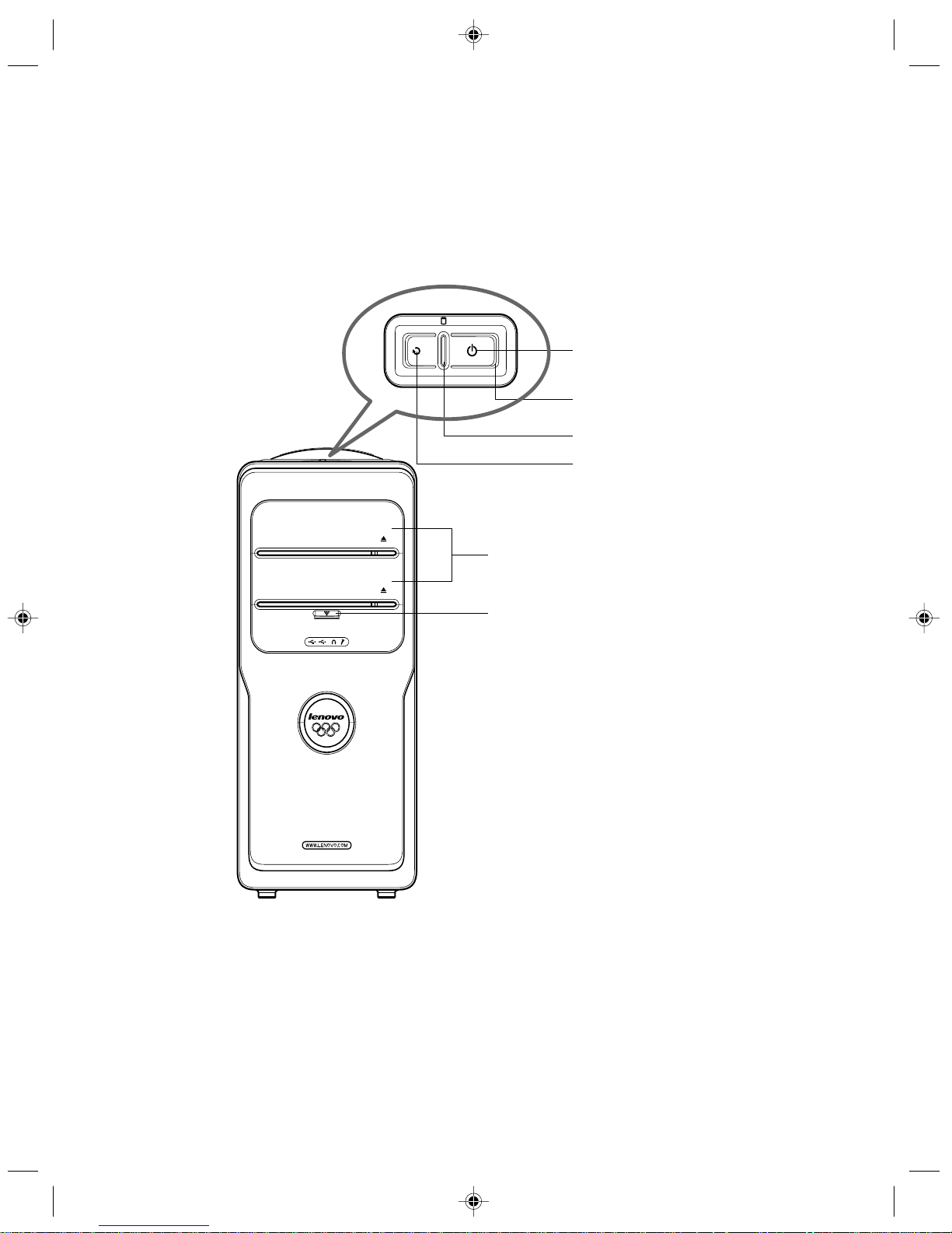
1.1 Front view of the computer
The following section shows the locations of the connectors on the front of the
computer.
Power button
Hard disk drive indicator
Power indicator
Optical drives
Front digital connectors
Reset
Power button: Press this button to turn on/off your computer.
Reset: Press this button to restart your computer. We recommend that you do not perform this operation in
normal condition.
Hard disk drive indicator: Indicates the read/write operation of the hard disk drive .
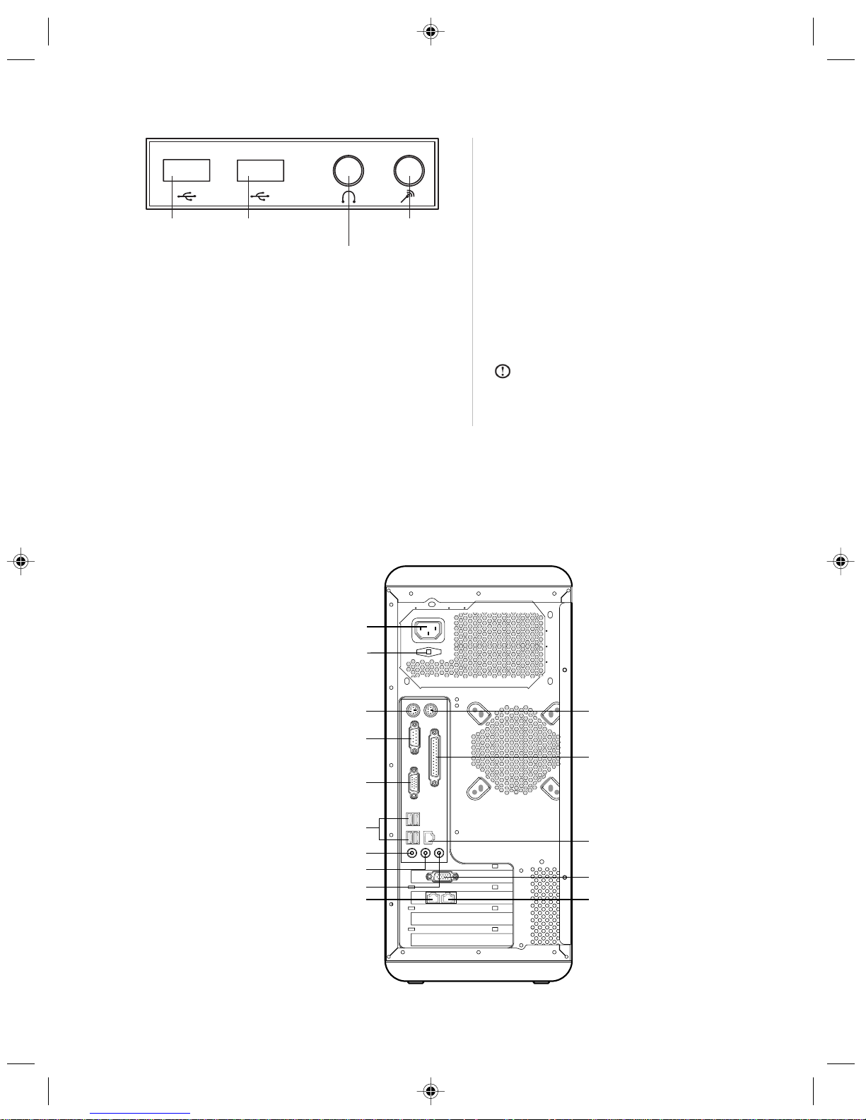
Front digital connectors: Pull down the cover plate of the front digital ports to expose a number of ports,
such as the USB connector, as shown below.
3
Lenovo 3000 H Series User Manual
USB
connector
USB
connector
Speaker/
headphone connector
Microphone
connector
USB connector: Used to attach devices
that require a USB connection.
Speaker/headphone connector: Used to
attach a microphone to your computer
when you want to record voice or capture
other sounds. Unplug the speaker
connector and connect the headphone
connector to use headphone.
Microphone connector: Connect to the
microphone to input the captured sound
into your computer.
Note:
No diskette drive is included in this
model. There might be an icon of diskette drive
in Windows. However, it does not work when
clicking on it.
1.2 Rear view of the computer
The following section shows the locations of the connectors on the rear of the computer.
Not all computer models will have the following connectors.
Power connector
Standard keyboard connector
Standard mouse connector
Serial connector
VGA monitor connector
USB connector
Microphone connector
Speaker/headphones connector
Audio line in connector
Modem
Parallel connector
Ethernet connector
Externtal VGA card connector
Telephone
LCD power connector
4
Lenovo 3000 H Series User Manual
Power connector: Used to supply power to the computer.
LCD power connector: Used to supply power to the LCD.
Standard mouse connector: Used to attach a mouse to a standard connector.
Standard keyboard connector: Used to attach a keyboard to a standard connector.
Serial connector: Used to attach serial devices that uses a 9-pin serial connector.
Parallel connector: Used to attach devices that requires a 25-pin parallel connection.
VGA monitor connector: Used to attach a VGA monitor to the computer.
Note: The VGA monitor connector in your computer is disabled when a monitor is connected to the external VGA card
connector on your computer.
USB connector: Used to attach devices that require a USB connection.
Ethernet connector: Used to attach to an Ethernet-type local area network or to a cable modem
Microphone connector: Used to attach a microphone to your computer when you want to record voice or
capture other sounds.
Speaker/headphones connector: Used to attach a speaker or headphones. Unplug the speaker
connector and connect the headphone connector to use headphone.
Audio line in connector: Used to receive audio signals from an external audio device, such as a stereo
system.
External VGA card connector: Used to attach a VGA monitor to the computer. If the VGA card has a S-
video port, then it can be connected to the TV to output the video signal. (Some models have external
VGA card.)
Modem: Used to attach your computer to a telephone line for modem use.
Telephone: Used to attach a telephone line to your computer for modem use.
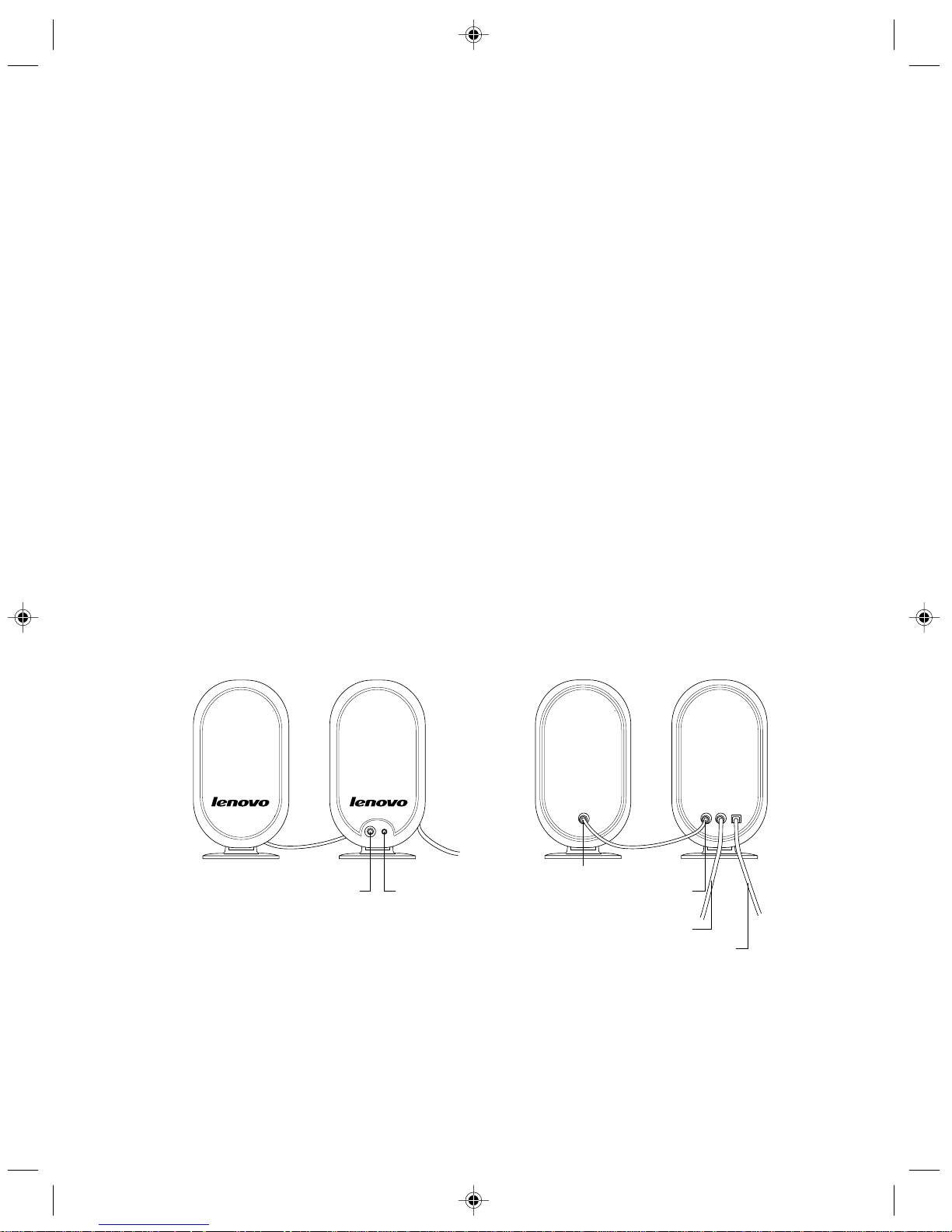
1.3 Speakers
Power switch
Volume adjustment
Connect the main speaker
Connect the sub speaker
Power Cable
Speaker/headphones cable
 Loading...