

Lenovo GCM16, GCM32 Quick Installation Manual
1
Before installing this product, read the
Safety Information and the Important
Notices and Warranty Information
document on the Documentation CD.
2
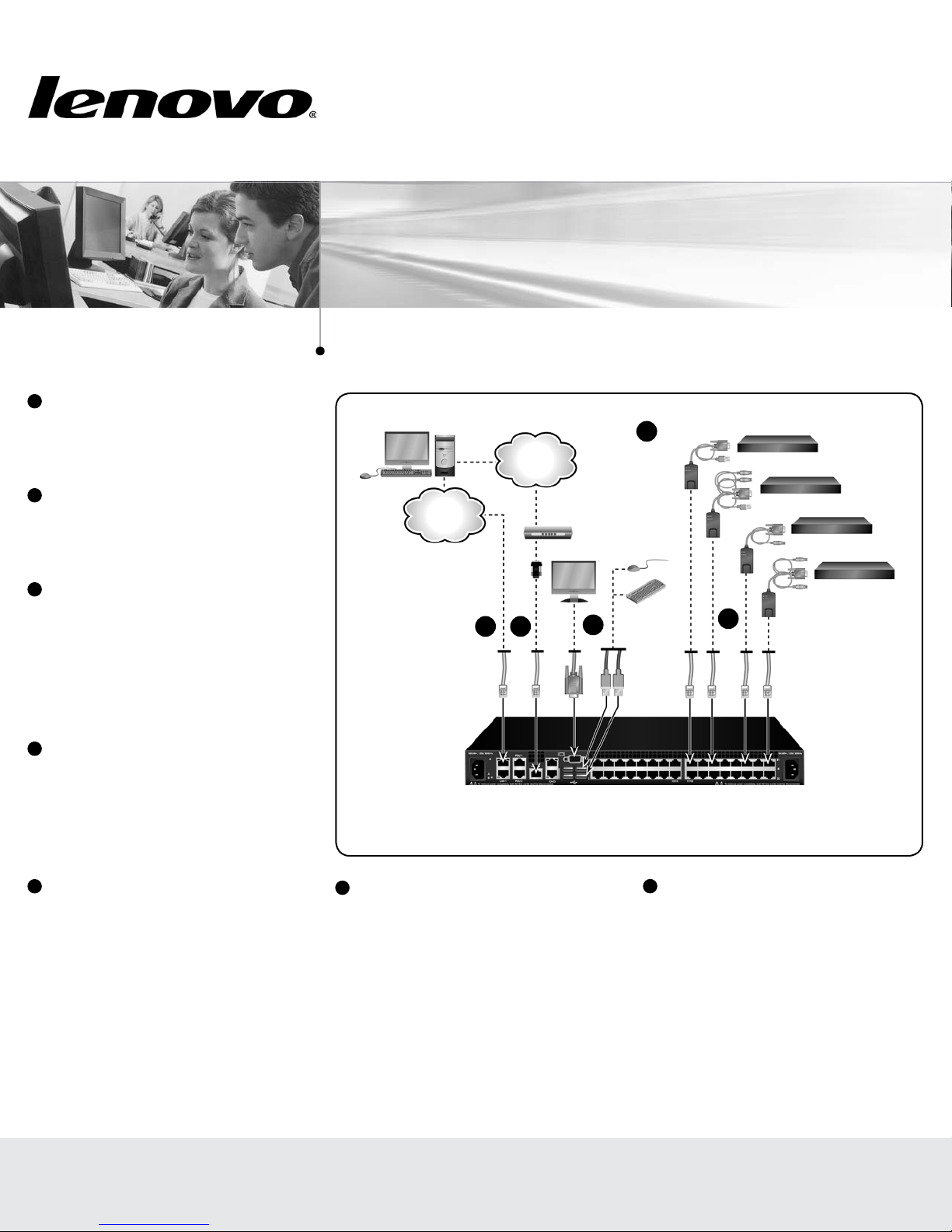
Connecting the local port
Connect your VGA monitor and USB keyboard
and mouse cables into the appropriately labeled
GCM16 or GCM32 switch ports.
3
Connecting a Conversion Option cable
to the GCM16 or GCM32 switch
Connect one end of a CAT 5 cable (4-pair, up
to 150 ft/45 m) into an available numbered
port on the rear of your GCM16 or GCM32
switch. Connect the other end into the RJ-45
connector of the Conversion Option cable.
Quick Installation Guide
Global Console Manager
GCM16 | GCM32
Connecting the GCM switch
3
IBM
Conversion
Option
4
Ethernet
Telephone
5 6
network
Modem
2
Target devices
4
Connecting a target device to a
Conversion Option cable
Connect a Conversion Option cable into the
appropriate port on the back of a target device.
Repeat steps 3 and 4 for all target devices you
want to connect.
5
Connecting network and remote users
Connect a customer supplied CAT 5 cable
from the Ethernet network into a LAN port on
the back of the GCM16 or GCM32 switch.
Network users will access the GCM16 or
GCM32 switch through this port.
First Edition, July 2015. Copyright Lenovo 2015.
LIMITED AND RESTRICTED RIGHTS NOTICE: If data or software is delivered pursuant a General Services Administration “GSA” contract, use, reproduction, or disclosure is subject to restrictions set forth in Contract No. GS-35F-05925.
Lenovo and the Lenovo logo are trademarks of Lenovo in the United States, other countries, or both.
Printed in USA
6
Connecting to an external modem
(optional)
The GCM16 or GCM32 switch may also be
accessed using an ITU V.92, V.90 or V.24-
compatible modem. Connect one end of a CAT
5 cable into the MODEM port on the GCM16
or GCM32 switch. Connect the other end into
the CAT 5 to DB-9 (male) adapter, which then
connects into the appropriate port on the back
of the modem.
Local USB
connection
GCM16 or GCM32 switch
(GCM32 shown)
7
Connecting a supported PDU to the
GCM16 or GCM32 switch (optional)
Connect one end of the RJ-45 cable supplied
with the Power Distribution Unit (PDU) into the
PDU1 port on the GCM16 or GCM32 switch.
Using the supplied RJ-45 adapter, connect the
other end into the PDU. Connect the power
cords from the target devices into the PDU.
Connect the PDU into an appropriate AC wall
outlet. Repeat this procedure for the PDU2
port to connect a second PDU, if desired.
590-xxx-501A
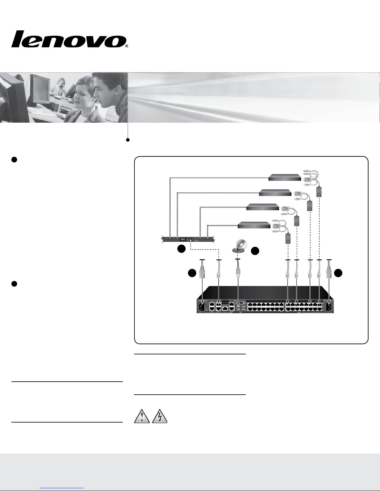
8
Connecting local virtual media or
smart cards (optional)
Connect virtual media devices or smart
card readers to any of the USB ports on the
GCM16 or GCM32 switch. To open a virtual
media session with a target device, the target
device must first be connected to the GCM16
or GCM32 switch using a virtual media
capable VCO or Virtual Media Conversion
Option G2 cable. To map a smart card with a
target device, the target device must first be
connected to the GCM16 or GCM32 switch
using a smart card capable Virtual Media
Conversion Option G2 cable.
9
Turning on target devices and
connecting power to the GCM16 or
GCM32 switch
Turn on each target device, then locate the
power cords that came with the GCM16 or
GCM32 switch. Connect one end into the
power socket on the rear of the GCM16 or
GCM32 switch and connect the other end
into an appropriate AC wall outlet. Repeat this
step for the second power cord to provide
redundant internal power supplies.
NOTE: Plugging the redundant power supplies
into separate branch circuits provides additional
redundancy in the event one external AC power
source loses power.
Quick Installation Guide
Quick Installation Guide
Global Console Manager
Global Console Manager
GCM16 | GCM32
GCM16 | GCM32
Connecting the GCM switch
Target devices
PDU
7
9 9
Local USB
connection
NOTE: The network settings can be configured
via the local port using the local user interface
or from a VT100 terminal emulator connected to
the serial setup port.
Safety precautions
DANGER
Electrical current from power, telephone, and
communication cables is hazardous.
8
External media
device
GCM16 or GCM32 switch
(GCM32 shown)
To avoid a shock hazard:
• Do not connect or disconnect any cables
or perform installation, maintenance, or
reconfiguration of this product during an
electrical storm.
• Connect all power cords to a properly
wired and grounded electrical outlet.
• Connect to properly wired outlets any
equipment that will be attached to this
product.
First Edition, July 2015. Copyright Lenovo 2015.
LIMITED AND RESTRICTED RIGHTS NOTICE: If data or software is delivered pursuant a General Services Administration “GSA” contract, use, reproduction, or disclosure is subject to restrictions set forth in Contract No. GS-35F-05925.
Lenovo and the Lenovo logo are trademarks of Lenovo in the United States, other countries, or both.
Printed in USA
590-xxx-501A
 Loading...