

Lenovo RackSwitch G8052, G8052, RackSwitch G8264, RackSwitch G8332 Installation Manual

Leno vo RackSwitch G8052
Installation Guide

Important Product Information—
Before using this information and the product it supports, read the Warranty Information document, Appendix B, “Notices” on page 77
and the Important Notices document. Also read the Safety Information document and the License Agreement for Machine Code
(LAMC) document on the Documentation CD and the Systems Environmental Notices and Users Guide document on the
Environmental Notices CD.
© Copyright 2015 Lenovo
US Government Users Restricted Rights—Use, duplication or disclosure restricted by GSA ADP Schedule Contract with Lenovo.
January 2015 Edition
Safety Information
Read the Safety Information
Before installing this product, read the Safety Information.
Antes de instalar este produto, leia as Informações de Segurança.
Prije instalacije ovog produkta obavezno pročitajte Surgonosne Upute.
Před instalací tohoto produktu si přečtěte příručku bezpečnostních instrukcí.
Læs sikkerhedsforskrifterne, før du installerer dette produkt.
Lees voordat u dit product installeert eerst de veiligheidsvoorschriften.
Ennen kuin asennat tämän tuotteen, lue turvaohjeet kohdasta Safety Information.
Avant d'installer ce produit, lisez les consignes de sécurité.
Vor der Installation dieses Produkts die Sicherheitshinweise lesen.’
Πριν εγκαταστήσετε το προϊόν αυτό, διαβάστε τις Πληροφορίες ασφαλείας
(safety information).
A termék telepítés előtt olvassa el a Biztonsági előírásokat!
Prima di installare questo prodotto, leggere le Informazioni sulla Sicurezza.
Πред да инсталира овој продукт, прочитајте информацијата за безбедност.
Les sikkerhetsinformasjonen (Safety Information) før du installerer dette produktet.
Przed zainstalowaniem tego produktu, należy zapoznać się z książką “Informacje
dotyczace bezpieczeństwa” (Safety Information).
© Copyright 2015 Lenovo Safety Information 3

Antes de instalar este produto, leia as Informações sobre Segurança.
Перед установкой продукта прочтитe инcтрyкции по тexникe безопасности.
Pred inštaláciou tohto zariadenia si prečítajte Bezpečnostné predpisy.
Pred namestitvijo tega proizvoda preberite Varnostne informacije.
Antes de instalar este producto, lea la información de seguridad.
Läs säkerhetsinformationen innan du installerar den här produkten.
Bu ürünü kurmadan önce güvenlik bilgilerini okuyun.
Youq mwngz yungh canjbinj neix gaxgonq, itdingh aeu doeg aen canjbinj soengq
cungj vahgangj ancien suisik.
4 RackSwitch G8052 Installation Guide
Safety Statement s
Important—
Each caution and danger statement in this document is labeled with a number. This
number is used to cross reference the English-language caution or danger
statement with the translated versions of the caution or danger statement in the
Safety Information document.
For example, if a caution statement is labeled “Statement 1,” translations for that
caution statement are in the Safety Information document under “Statement 1.”
Be sure to read all caution and danger statements in this document before you
perform the procedures. Read any additional safety information that comes with the
system or optional device before you install the device.
Following is a compilation of the statements found throughout this manual.
Statement 3
CAUTION:
When laser products (such as CD-ROMs, DVD drives, fiber optic devices, or
transmitters) are installed, note the following:
•
•
Do not remove the covers. Removing the covers of the laser prod uct could
result in exposure to hazardous laser radiation. There are no serviceable
parts inside the device.
Use of controls or adjustments or performance of pr oc edures other than
those specified herein might result in hazardous radiation exposure.
DANGER
Some laser products contain an embedded Class 3A or Class 3B laser
diode. Note the following.
Laser radiation when open. Do not stare into the beam, do not view directly
with optical instruments, and avoid direct exposure to the beam.
Class 1 Laser Product
Laser Klasse 1
Laser Klass 1
Luokan 1 Laserlaite
Appareil À Laser de Classe 1
© Copyright 2015 Lenovo Safety Information 5
Statement 5
1
2
CAUTION:
The power control button on the device and the power switch on the power
supply do not turn off the electrical current supplied to the device. The de vice
also might have more than one power cord. To remove all electrical current
from the device, ensure that all power cord s are disconnecte d from the power
source.
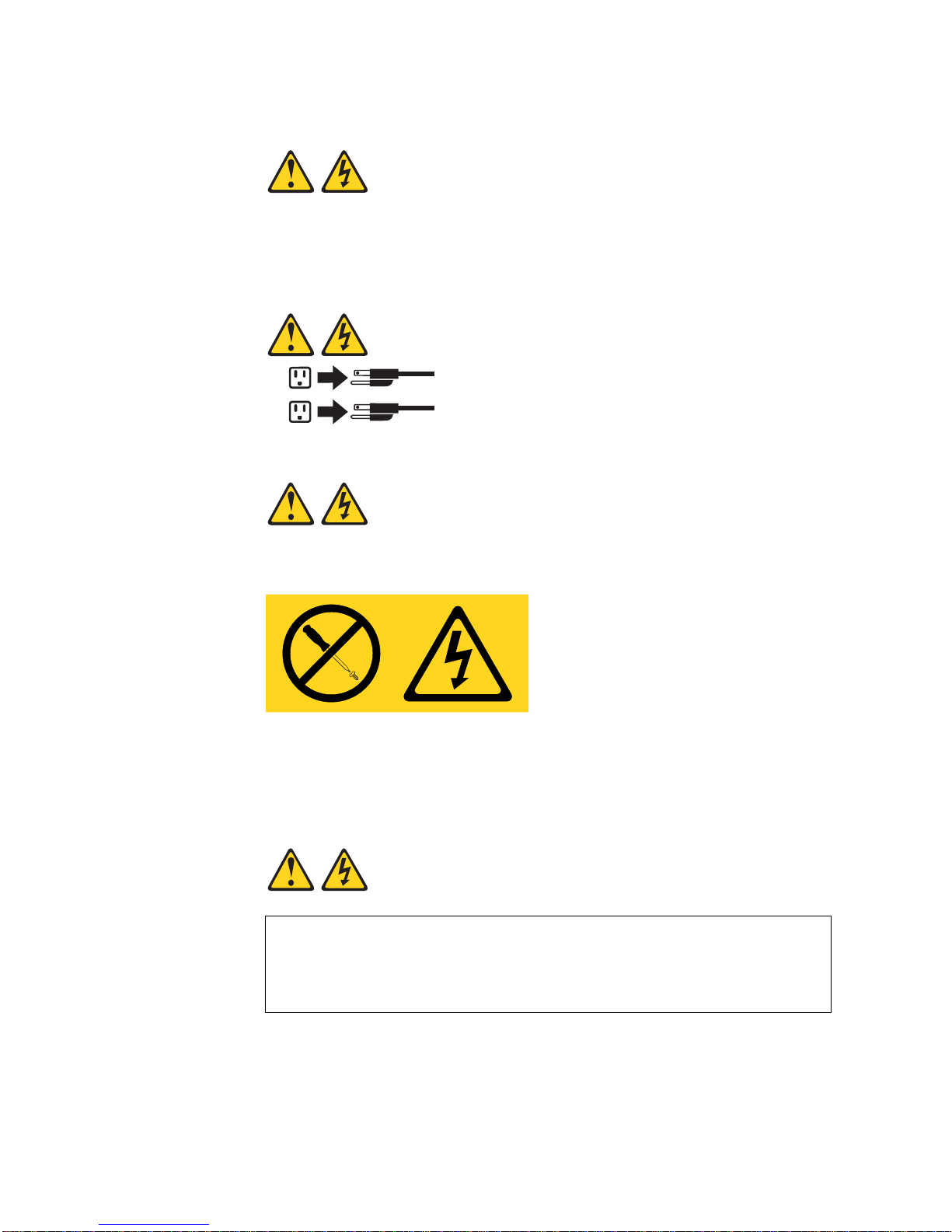
Statement 8
CAUTION:
Never remove the cover on a power supply or any part that has the following
label attached.
Hazardous voltage, current, and energy levels are present inside any
component that has this label attac hed. The re are no servi ceable parts inside
these components. If you suspect a problem wi th one of these p arts, c ontact a
service technician.
Statement 13
DANGER
Overloading a branch circuit is potentially a fire hazard and a shock hazard
under certain conditions. To avoid these hazards, ensure that your system
electrical requirements do not exceed branch circuit protection
requirements. Refer to the information that is prov ided with your device for
electrical specifications.
6 RackSwitch G8052 Installation Guide
Statement 25
CAUTION:
This product contains a Class 1M laser. Do not view directly with optical
instruments.
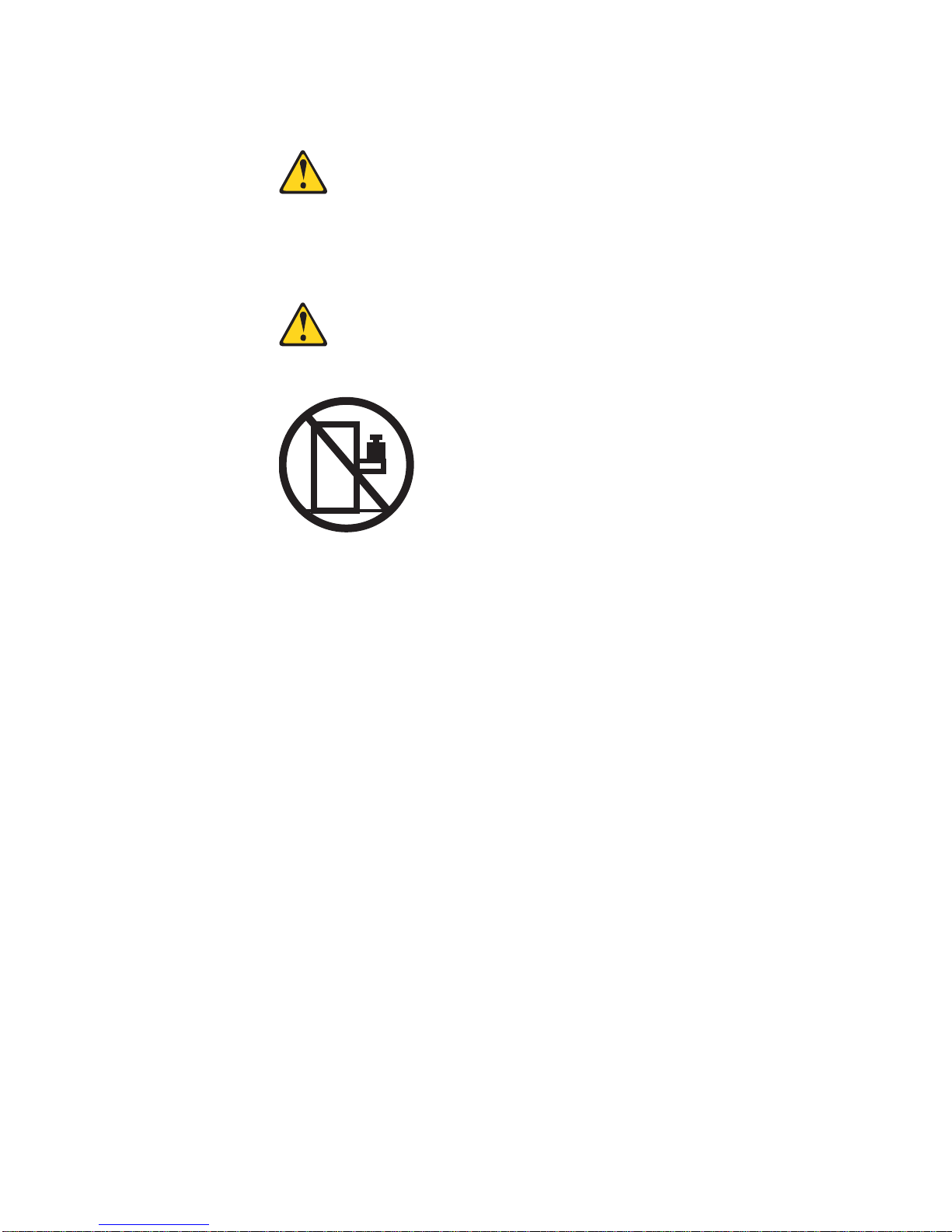
Statement 26
CAUTION:
Do not place any object on top of rack-mounted devices.
© Copyright 2015 Lenovo Safety Information 7

Statement 31
DANGER
Electrical current from power, telephone, and communication cables is
hazardous.
To avoid a shock hazard:
•
Do not connect or disconnect any cables or perform installation,
maintenance, or reconfiguration of this produ ct during an electrical storm.
•
Connect all power cords to a properly wired and grounded power source.
•
Connect to properly wired power sources any equipment that will be
attached to this product.
•
When possible, use one hand only to connect or disconnect signal cables.
•
Never turn on any equipment when there is evidence of fire, water, or
structural damage.
•
Disconnect the attached ac power cords, dc power sources, network
connections, telecommunications systems, and seria l cables before you
open the device covers, unless instructed otherwise in the installation
and configuration procedures.
•
Connect and disconnect cables as described in th e following table when
you install, move, or open covers on this product or attached devices.
To Connect:
1. Turn OFF all power sources and
equipment that is to be attached to
this product.
2. Attach signal cables to the product.
3. Attach power cords to the product.
– For ac systems, use appliance
inlets.
– For dc systems, ensure correct
polarity of -48 V dc connections:
RTN is + and -48 V dc is -. Earth
ground should use a two-hole
lug for safety.
4. Attach signal cables to other
devices.
5. Connect power cords to their
sources.
6. Turn ON all the power sources.
To Disconnect:
1. Turn OFF all power sources and
equipment that is to be attached to
this product.
– For ac systems, remove all
power cords from the chassis
power receptacles or interrupt
power at the ac power
distribution unit.
– For dc systems, disconnect dc
power sources at the breaker
panel or by turning off the power
source. Then, remove the dc
cables.
2. Remove the signal cables from the
connectors.
3. Remove all cables from the
devices.
8 RackSwitch G8052 Installation Guide
Statement 37
DANGER
When you populate a rack cabinet, adhere to the following guidelines:
•
Always lower the leveling pads on th e rack cabinet.
•
Always install the stabilizer brackets on the rack cabine t.
•
Always install the heaviest devices in the bottom of the rack cabine t.
•
Always install devices starting from the bottom of the rack cabinet.
•
Do not extend multiple devices from the rack cabinet simultaneously,
unless the rack-mounting instructions direction you to do so. Multiple
devices extended into the service position can cause your rack cabinet
to tip.
•
If you are not using the Lenovo 9308 rack cabinet, securely an chor the
rack cabinet to ensure its stability.
Other Important Safety Notices
Important
This product is also designed for IT power distribution systems with phase-to-phase
voltage of 230V.
Important
Machinenlärminformations-Verordnung—3. GPSGV, der höchste Shalldruckpegel
beträgt 70 dB (A) oder weniger.
© Copyright 2015 Lenovo Safety Information 9

10 RackSwitch G8052 Installation Guide

Contents
Safety Information . . . . . . . . . . . . . . . . . . . . . . . .3
Read the Safety Information . . . . . . . . . . . . . . . . . . . . . 3
Safety Statements . . . . . . . . . . . . . . . . . . . . . . . . . 5
Other Important Safety Notices . . . . . . . . . . . . . . . . . . . . 9
Chapter 1. The RackSwitch G8052 . . . . . . . . . . . . . . . . . 15
Introduction . . . . . . . . . . . . . . . . . . . . . . . . . . . 15
G8052 Documentation . . . . . . . . . . . . . . . . . . . . . . 15
About this Installation Guide. . . . . . . . . . . . . . . . . . . 15
Notices and Statements in this Document . . . . . . . . . . . . . 16
The Documentation CD . . . . . . . . . . . . . . . . . . . . 16
Related Documentation . . . . . . . . . . . . . . . . . . . . 17
Chapter 2. Switch Components . . . . . . . . . . . . . . . . . . 19
Switch Unit . . . . . . . . . . . . . . . . . . . . . . . . . . . 19
Management Panel. . . . . . . . . . . . . . . . . . . . . . . . 20
Mini-USB Serial Console Port . . . . . . . . . . . . . . . . . . 20
RJ-45 Management Port . . . . . . . . . . . . . . . . . . . . 21
Reset Button. . . . . . . . . . . . . . . . . . . . . . . . . 21
System Status LEDs . . . . . . . . . . . . . . . . . . . . . 22
USB Port . . . . . . . . . . . . . . . . . . . . . . . . . . 22
Switching Ports . . . . . . . . . . . . . . . . . . . . . . . . . 22
SFP+ Ports . . . . . . . . . . . . . . . . . . . . . . . . . 23
RJ-45 Ports . . . . . . . . . . . . . . . . . . . . . . . . . 24
Rear Panel . . . . . . . . . . . . . . . . . . . . . . . . . . . 25
Fans . . . . . . . . . . . . . . . . . . . . . . . . . . . . 25
Power Supply . . . . . . . . . . . . . . . . . . . . . . . . 25
Chapter 3 . Inst alling G8052 Hardware and Options . . . . . . . . . . 29
Before Installing the G8052 . . . . . . . . . . . . . . . . . . . . 30
Recording Important Product Information . . . . . . . . . . . . . 30
Required Tools . . . . . . . . . . . . . . . . . . . . . . . . 31
Package Contents . . . . . . . . . . . . . . . . . . . . . . 31
Environmental Requirements . . . . . . . . . . . . . . . . . . 31
Preventing Electric Shock . . . . . . . . . . . . . . . . . . . 32
Handling Static-Sensitive Devices . . . . . . . . . . . . . . . . 34
Cabling Guidelines . . . . . . . . . . . . . . . . . . . . . . 34
Installing the G8052 in a Rack . . . . . . . . . . . . . . . . . . . 35
Installing the G8052 in a Standard Equipment Rack . . . . . . . . . 35
Installing the G8052 in a Lenovo System x or Power Rack . . . . . . . 37
Installing the G8052 in a Lenovo iDataPlex Rack . . . . . . . . . . 41
Installing the 1U Air Duct Option. . . . . . . . . . . . . . . . . . . 44
Installing Port Transceivers . . . . . . . . . . . . . . . . . . . . 48
Installing an SFP Copper Transceiver . . . . . . . . . . . . . . . 48
Installing an SFP Optical Transceiver . . . . . . . . . . . . . . . 48
Installing an SFP+ Optical Transceiver . . . . . . . . . . . . . . 50
© Copyright 2015 Lenovo Contents 11

Chapter 4. Removing and Replacing G8052 Components . . . . . . . 53
Removing Port Transceivers . . . . . . . . . . . . . . . . . . . . 53
Removing and Replacing a Power Supply Module . . . . . . . . . . . 54
Removing the Power Supply Module . . . . . . . . . . . . . . . 54
Replacing the Power Supply Module . . . . . . . . . . . . . . . 56
Removing and Replacing a Fan Module . . . . . . . . . . . . . . . 58
Removing the Fan Module . . . . . . . . . . . . . . . . . . . 58
Replacing the Fan Module . . . . . . . . . . . . . . . . . . . 59
Removing the G8052 from a Standard Equipment Rack . . . . . . . . . 60
Removing the G8052 from a Lenovo System x or Power Rack. . . . . . . 61
Removing the G8052 from a Lenovo iDataPlex Rack . . . . . . . . . . 64
Removing the 1U Air Duct Option . . . . . . . . . . . . . . . . . . 66
Replacing the G8052 . . . . . . . . . . . . . . . . . . . . . . . 67
Preparing and Returning the G8052 . . . . . . . . . . . . . . . 67
Configuring Vital Product Data . . . . . . . . . . . . . . . . . 67
Chapter 5. Initializing the G8052. . . . . . . . . . . . . . . . . . 69
System Status LEDs . . . . . . . . . . . . . . . . . . . . . . . 69
Connecting to the Switch . . . . . . . . . . . . . . . . . . . . . 69
Using the Serial Console Port . . . . . . . . . . . . . . . . . . 69
Using the Management Port . . . . . . . . . . . . . . . . . . 70
Logging In to the Switch. . . . . . . . . . . . . . . . . . . . . . 70
Default Configuration Files. . . . . . . . . . . . . . . . . . . . . 70
Configuring an IP Interface for Remote Access. . . . . . . . . . . . . 71
Updating Firmware. . . . . . . . . . . . . . . . . . . . . . . . 72
Using the Boot Management Menu . . . . . . . . . . . . . . . . . 72
Chapter 6. Troubleshooting . . . . . . . . . . . . . . . . . . . 73
System LED Is Not Lit . . . . . . . . . . . . . . . . . . . . . . 73
Port Link LED Is Not Lit . . . . . . . . . . . . . . . . . . . . . . 73
Temperature Sensor Warning . . . . . . . . . . . . . . . . . . . 73
Switch Does Not Initialize (Boot) . . . . . . . . . . . . . . . . . . 73
Appendix A. Getting Help and Technical Assistance . . . . . . . . . 75
Before You Call . . . . . . . . . . . . . . . . . . . . . . . . . 75
Opening a Support Request . . . . . . . . . . . . . . . . . . . . 75
Using the Documentation . . . . . . . . . . . . . . . . . . . . . 76
12 RackSwitch G8052 Installation Guide

Appendix B. Notices. . . . . . . . . . . . . . . . . . . . . . . 77
Trademarks. . . . . . . . . . . . . . . . . . . . . . . . . . . 78
Important Notes . . . . . . . . . . . . . . . . . . . . . . . . . 79
Recycling information . . . . . . . . . . . . . . . . . . . . . . . 79
Particulate Contamination . . . . . . . . . . . . . . . . . . . . . 80
Telecommunication Regulatory Statement. . . . . . . . . . . . . . . 81
Electronic Emission Notices . . . . . . . . . . . . . . . . . . . . 81
Federal Communications Commission (FCC) Statement . . . . . . . 81
Avis de Conformité à la Réglementation d'Industrie Canada . . . . . . 81
Australia and New Zealand Class A Statement . . . . . . . . . . . 81
European Union EMC Directive Conformance Statement . . . . . . . 81
Germany Class A Statement . . . . . . . . . . . . . . . . . . 82
VCCI Class A Statement . . . . . . . . . . . . . . . . . . . . 83
Japan Electronics and Information Technology Industries Association
(JEITA) Statement . . . . . . . . . . . . . . . . . . . . . 83
Korea Communications Commission (KCC) Statement . . . . . . . . 83
Russia Electromagnetic Interference (EMI) Class A Statement . . . . . 84
People’s Republic of China Class A Electronic Emission Statement . . . 84
Taiwan Class A Compliance Statement . . . . . . . . . . . . . . 84
Appendix C. Technical Specifications . . . . . . . . . . . . . . . 85
Physical Characteristics . . . . . . . . . . . . . . . . . . . . . . 85
Environmental Specifications . . . . . . . . . . . . . . . . . . . . 85
Power Specifications . . . . . . . . . . . . . . . . . . . . . . . 86
Switching Performance . . . . . . . . . . . . . . . . . . . . . . 86
© Copyright 2015 Lenovo Contents 13

14 RackSwitch G8052 Installation Guide

Chapter 1. The RackSwitch G8052
Introduction
This Installation Guide provides information about the Lenovo
G8052 (referred to as G8052 throughout this document).
The G8052 is a 1U rack-mountable aggregation switch with unmatched line-rate
Layer 2 and Layer 3 performance. The G8052 uses a wire-speed, non-blocking
switching fabric that provides simultaneous wire-speed transport of multiple packets
at low latency on all ports.
The G8052 contains the following switching ports:
•
Forty-eight Gigabit Ethernet (GbE) RJ-45 ports
•
Four 10 GbE Small Form Pluggable Plus (SFP+) ports
SFP+ ports
Direct-Attach Cables (DACs), and QSFP+ ports can be populated with optical
QSFP+ modules or DACs
The G8052 is rack-mountable in either the horizontal or vertical direction, depending
on your application. Mounting options are available for a variety of rack systems (as
described in Chapter 3, “Installing G8052 Hardware and Options.”
For superior reliability, the G8052 uses redundant, hot-swap power supply modules
and four hot-swap fan modules. Module options are available for either front-to-rear
airflow, or rear-to-front airflow.
You can manage the switch through the local console port, or through a remote
network connection, a Web browser-based interface, or SNMP-based network
management software. For more information, see Chapter 5, “Initializing the G8052”
on page 69.
can be populated with optical or copper transceiver modules or
.
®
RackSwitch™
Note: Other features supported on your switch depend on the specific firmware
installed. For more information, see the Application Guide and Command
Reference for your specific switch and its installed firmware.
G8052 Documentation
About this Installation Guide
This Installation Guide provides information and instructions for installing the
G8052, updating the firmware, and solving problems. For other information about
configuration and management of the switch, refer to the documents described in
“Related Documentation” on page 17.
Note:
•
The illustrations in this document might differ slightly from your hardware.
•
The console output described or referenced in this document might differ slightly
from that displayed by your system. Output varies according to the type of
Lenovo chassis and the firmware versions and options that are installed.
© Copyright 2015 Lenovo 15

Notices and St atement s in this Document
The caution and danger statements in this document are also in the multilingual
Safety Information document, which is on the included Documentation CD. Each
statement is numbered for reference to the corresponding statement in the Safety
Information document.
The following notices and statements are used in this document:
•
Note:
These notices provide important tips, guidance, or advice.
•
Important:
avoid inconvenient or problem situations.
•
Attention:
data. An attention notice is placed just before the instruction or situation in which
damage could occur.
•
Caution:
to you. A caution statement is placed just before the description of a potentially
hazardous procedure step or situation.
•
Danger:
extremely hazardous to you. A danger statement is placed just before the
description of a potentially lethal or extremely hazardous procedure step or
situation.
These notices provide information or advice that might help you
These notices indicate potential damage to programs, devices, or
These statements indicate situations that can be potentially hazardous
These statements indicate situations that can be potentially lethal or
The Documentation CD
The included Documentation CD contains documentation for your switch in Portable
Document Format (PDF).
The Documentation CD includes the product Safety Information document and the
License Machine Access Code (LAMC) document. The Environmental Notices CD
includes the Environmental Notices for the product.
The Documentation CD requires the following minimum hardware and software:
•
Microsoft Windows NT 4.0 (with Service Pack 3 or later), Windows 2000, or Red
Hat Linux.
•
100 MHz microprocessor.
•
32 MB of RAM.
•
Adobe Acrobat Reader 3.0 (or later), or xpdf (which comes with Linux operating
systems). PDF reader software is required for reading documents on the CD.
To access the documents on the CD:
•
If you are using a Windows operating system, insert the CD into the CD or DVD
drive and from My Computer, double click the CD or DVD drive, then open the
folders and documents that support your product.
•
If you are using a Linux operating system, insert the CD into the CD or DVD drive
and run the following command from the
sh.linux.sh
When the CD is mounted, open the directories and documents that support your
product.
mnt/cd
directory:
16 RackSwitch G8052 Installation Guide

Related Documentation
Additional or updated product documents may be available from the Lenovo
website. Such documents may cover features not described in the original
documentation that comes with the switch, or may include technical updates or
corrections.
You can obtain up-to-date information on the Lenovo support website:
http://support.lenovo.com/
Note: Changes are made periodically to the Lenovo website. Procedures for
locating firmware and documentation might vary slightly from what is
described in this document.
For information about switch hardware and firmware features, specifications, and
standards, including their configuration, see the Application Guide for your specific
switch and its installed firmware.
For information about the switch information, statistics, and individual configuration
parameters, see the Command Reference guide for your specific switch and its
installed firmware.
© Copyright 2015 Lenovo Chapter 1: The RackSwitch G8052 17

18 RackSwitch G8052 Installation Guide
Chapter 2. Switch Component s
Management
Panel
SFP+ PortsRJ-45 Ports
OK
~AC
!
OK
~AC
!
Power Supply
Module
Power Connector
IEC320 IEC320
Power Connector
Fan Modules Power Supply
Module
This chapter describes the G8052 hardware components.
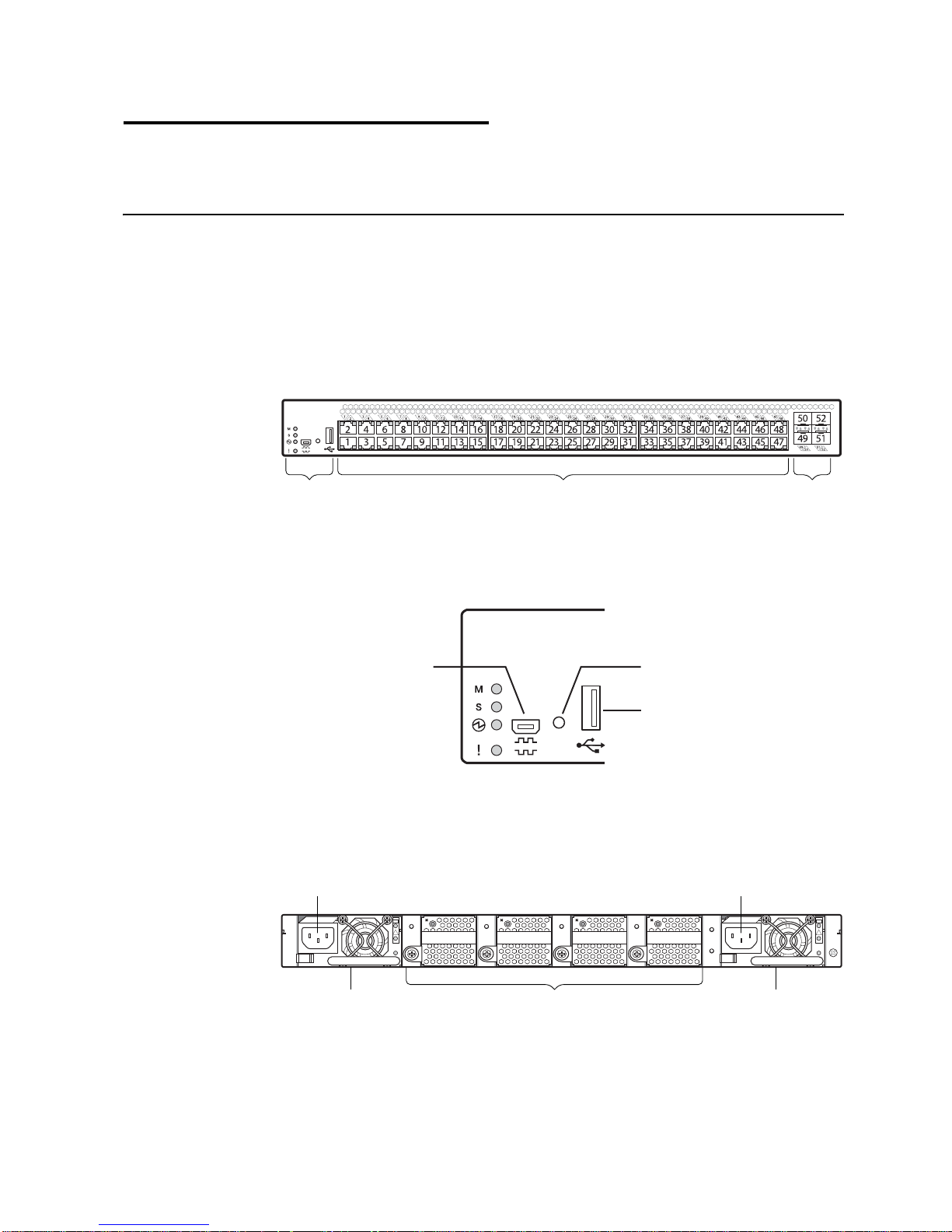
Switch Unit
The G8052 is a 1U rack-mountable GbE switch. You can mount the switch in either
the horizontal or vertical direction.
The following illustrations show the features on the front and rear of the switch.
Figure 1. RackSwitch G8052 front panel
Figure 2. RackSwitch G8052 management panel detail
Serial Console Port
Status LEDs
Figure 3. RackSwitch G8052 rear panel
Reset ButtonMini-USB
USB Port
© Copyright 2015 Lenovo 19
Management Panel
Mini-USB Serial Console Port
The mini-USB port on the front management panel is available for switch console
management. The port operates using RS-232 serial communications. A compatible
console cable kit is included with the switch.
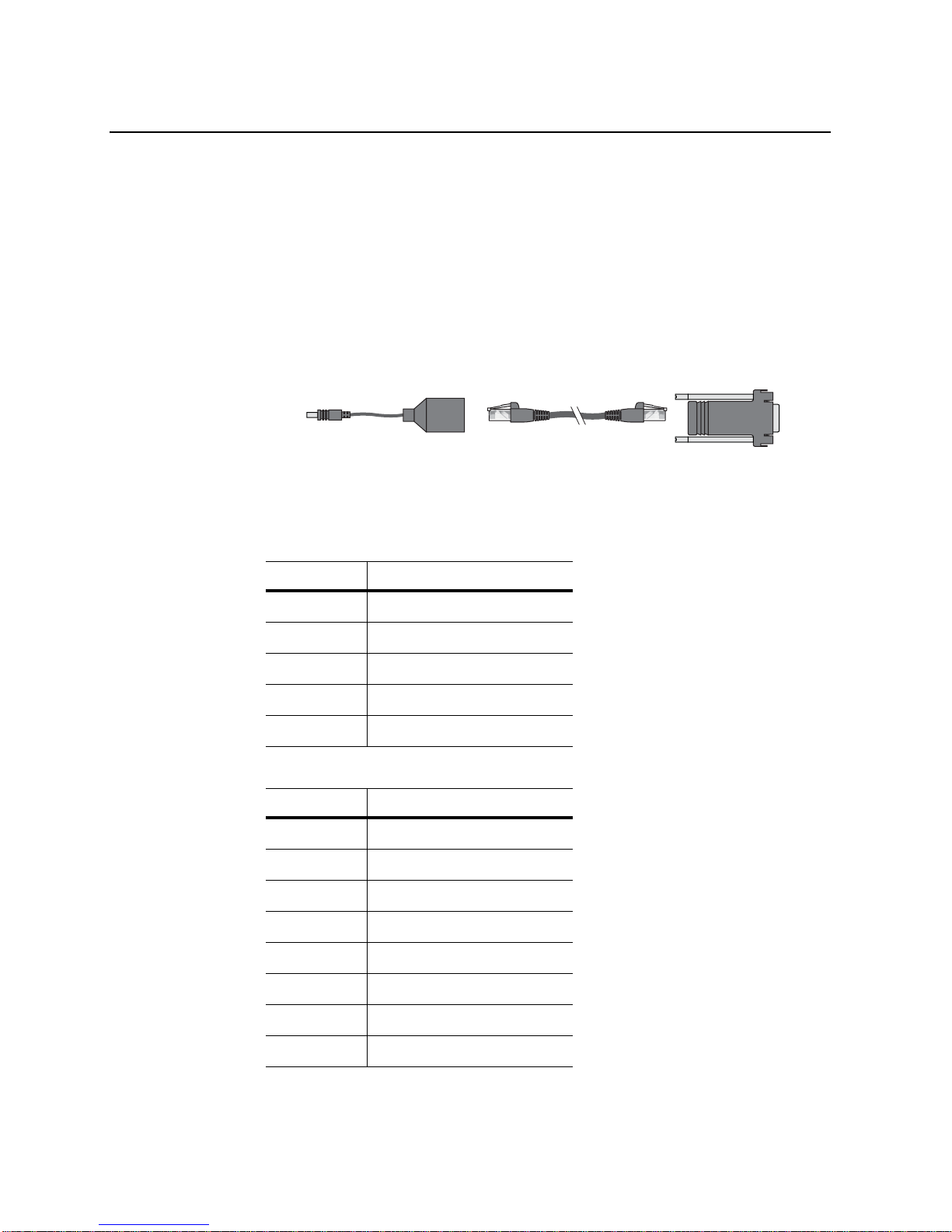
To connect a computer or terminal to the switch using the included kit, first connect
the console cable to the mini-USB port on the front panel. Connect one end of the
Category 5 patch cable to the RJ-45 port on the console cable, and the other end of
the patch cable to the RJ-45-to-DB9 adapter (see the following illustration).
Figure 4. Console cable connections
To
Switch
Switch
Console Cable
Category 5
Patch Cable
RJ-45 Adapter
If using cables other than those from the included kit, ensure that they are
compatible with the port pin assignments shown in the following tables.
Table 1. Switch mini-USB port connector pin assignments
Pin Number Function
1 No connect
2 SIN (RS-232 Input)
3 SOUT (RS-232 Output)
4 GND (Ground)
5 No connect
Table 2. Console cable RJ-45 port connector pin assignments
Pin Number Function
1 RTS (Request To Send)
To P C
Terminal
2 DTR (Data Terminal Ready)
3 TxD (Transmit Data)
4 GND (Ground)
5 GND (Ground)
6RxD (Receive Data)
7 DSR (Data Set Ready)
8 CTS (Clear To Send)
20 RackSwitch G8052 Installation Guide
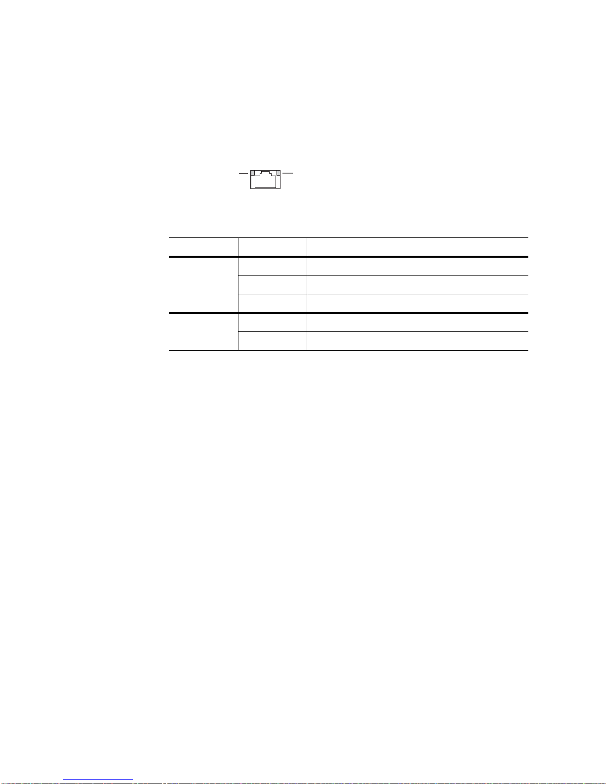
RJ-45 Management Port
Link LED
Speed LED
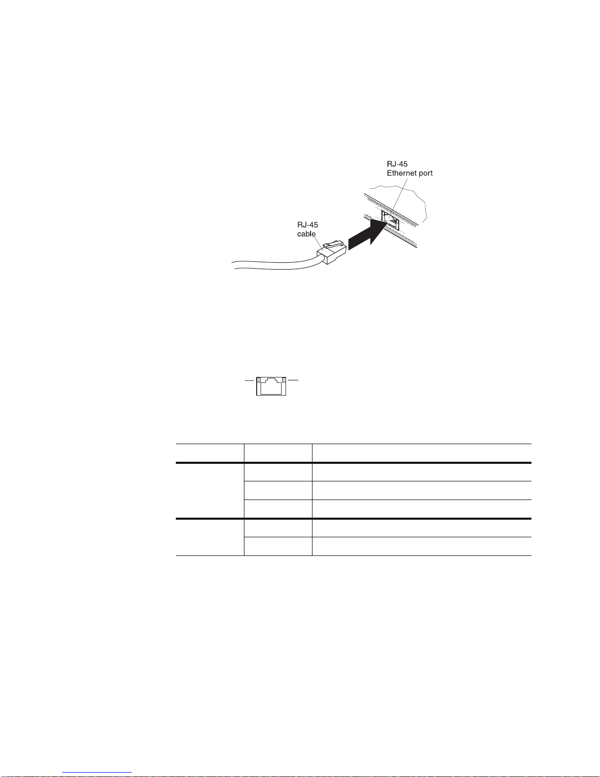
The RJ-45 management port on the front panel supports 10/100/1000BASE-T,
in-line switch management.
To attach an RJ-45 connector to the switch, push the RJ-45 cable connector into the
port connector until it clicks into place.
To disconnect the RJ-45 cable, squeeze the release tab and gently pull the cable
connector out of the switch connector.
RJ-45 Management LEDs
The RJ-45 management port LEDs are oriented as shown in the following figure.
Figure 5. RJ-45 management port LEDs
Reset Button
Status LEDs for the RJ-45 management port are described in the following table.
Table 3. RJ-45 status LEDs behavior
LED State Functional Meaning
Link Steady green Link up
Flashing green Activity
Off No link
Speed Steady green 100/1000 Megabits per second (Mbps)
Off 10 Mbps or no link
The Reset button is recessed within a hole on the front panel. Use a straightened
paper clip or similar object to press the Reset button. The Reset button allows
technicians to reset the switch as follows:
•
Normal reset—Press and release Reset. The switch resets and reloads the
configuration files.
•
Factory reset—Press and hold Reset for more than five seconds. The switch
resets and reverts all configuration settings to the factory defaults.
© Copyright 2015 Lenovo Chapter 2: Switch Components 21
System Status LEDs
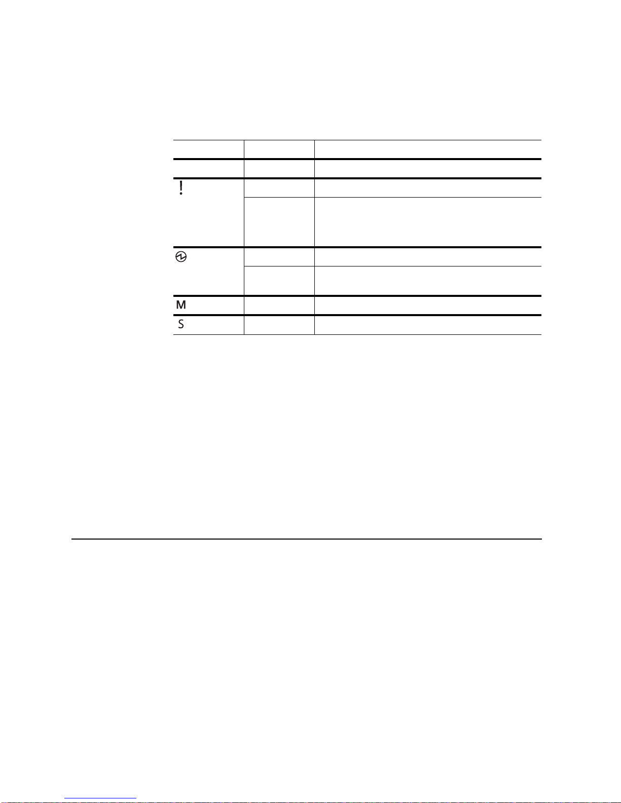
The following table describes the behavior of the system status LEDs:
Table 4. System status LEDs behavior
LED State Functional Meaning
All Off Total power failure.
- Service Steady blue Device is a Backup/Member in a stack.
- Power Steady green Power is OK.
1
Flashing blue Service is required due to failure of the general system,
stacking function, or its power module. The specific
failure is indicated in conjunction with the other system
status LEDs.
USB Port
Switching Ports
Flashing green Power supply failure or disconnection. Service is
- Master
- Member1Steady green Device is a Backup/Member in a stack.
Note 1:
1
Steady green Device is the Master in a stack.
Support for the stacking feature depends on the installed firmware. To
required.
2
2
determine whether your switch supports stacking, see the Application Guide for your
specific switch and firmware version.
Note 2:
If service required is due to a stacking error, either the Master or Member
LED may be steady green, depending on the last known good state, or both LEDs
may be steady green to indicate a general stacking error.
The USB port enables you to connect a USB drive to the switch. You can copy files
from the switch to the USB drive, or from the USB drive to the switch. You can also
start the switch using files on the USB drive.
For more information about using the USB drive, see the RackSwitch G8052
Release Notes.
The G8052 contains the following switching ports:
•
Four 10 GbE SFP+ ports
•
Forty-eight fixed 10/100/1000 megabits per second (Mbps) auto-sensing,
auto-MDIX RJ-45 ports
SFP+ ports
Direct-Attach Cables (DACs).
The switching ports are described in the following sections. For information about
ports on the management panel, see “Management Panel” on page 20.
22 RackSwitch G8052 Installation Guide
can be populated with optical or copper transceiver modules or
SFP+ Ports
Statement 3
CAUTION:
When laser products (such as CD-ROMs, DVD drives, fiber optic devices, or
transmitters) are installed, note the following:
•
Do not remove the covers. Removing the covers of the laser prod uct could
result in exposure to hazardous laser radiation. There are no serviceable
parts inside the device.
•
Use of controls or adjustments or performance of pr oc edures other than
those specified herein might result in hazardous radiation exposure.
DANGER
Some laser products contain an embedded Class 3A or Class 3B laser
diode. Note the following.
Laser radiation when open. Do not stare into the beam, do not view directly
with optical instruments, and avoid direct exposure to the beam.
Class 1 Laser Product
Laser Klasse 1
Laser Klass 1
Luokan 1 Laserlaite
Appareil À Laser de Classe 1
Four 10 GbE SFP+ ports are available on the front panel . These ports accept
supported optical or copper SFP or SFP+ transceivers, or DACs. Transceivers must
be purchased separately.
SFP+ LEDs
Status LEDs for the SFP+ ports are described in the following table.
Table 5. SFP+ port status LED behavior
LED State Functional Meaning
Link Steady green Link up
Off No link
Flashing green Activity
Speed Steady green 10 Gbps
© Copyright 2015 Lenovo Chapter 2: Switch Components 23
Off 1 Gbps or no link
RJ-45 Ports
Link LED
Speed LED
There are forty-eight 10/100/1000BASE-T Gigabit Ethernet (GbE) RJ-45 ports on
the front of the G8052.
The RJ-45 port LEDs are oriented as shown Figure 5.
Figure 6. RJ-45 port status LEDs
Status LEDs for the RJ-45 ports are described in the following table.
Table 6. RJ-45 port status LED behavior
LED State Functional Meaning
Link Steady green Link up
Off No link
Flashing green Activity
Speed Steady green 100/1000 Mbps
Off 10 Mbps or no link
24 RackSwitch G8052 Installation Guide
Rear Panel
1
2
Fans
For cooling, the rear panel of the G8052 has four bays for hot-swap fan modules.
Four fan modules are required for redundancy. When four fan modules are used, if
there is a failure of one of the four fans, the switch reports the condition, the other
fans continue to run, and the switch continues to operate normally. You can replace
the failed hot-swap fan module while the switch is operating. If a second fan fails,
the switch reports the condition and shuts down to prevent overheating.
Fan operation and internal temperatures are monitored. If the air temperature
exceeds a desired threshold, the environmental monitor displays warnings.
Note: If a fan fails, the maximum operating temperature drops from +40°C (104°F)
to +35°C (95°F).
Fan LEDs
Fan LED indicators are located on the rear panel of the switch, on the individual fan
modules. The following table describes the fan module LED behavior.
Table 7. Fan module status LED behavior
LED State Functional Meaning
On Fan is operational
Power Supply
Off Fan module has no power.
Flashing Fan speed has failed. Replace the fan module.
The rear panel of the G8052 has two bays for hot-swap power supply modules.
Each power supply module has an individual IEC 320 C14 power connector. The
power cord attaches to a universal grounded AC power source.
Statement 5
CAUTION:
The power control button on the device and the power switch on the power
supply do not turn off the electrical current supplied to the dev ice. The device
also might have more than one power cord. To remove all electrical current
from the device, ensure that all power cords are disco nnected from the powe r
source.
© Copyright 2015 Lenovo Chapter 2: Switch Components 25
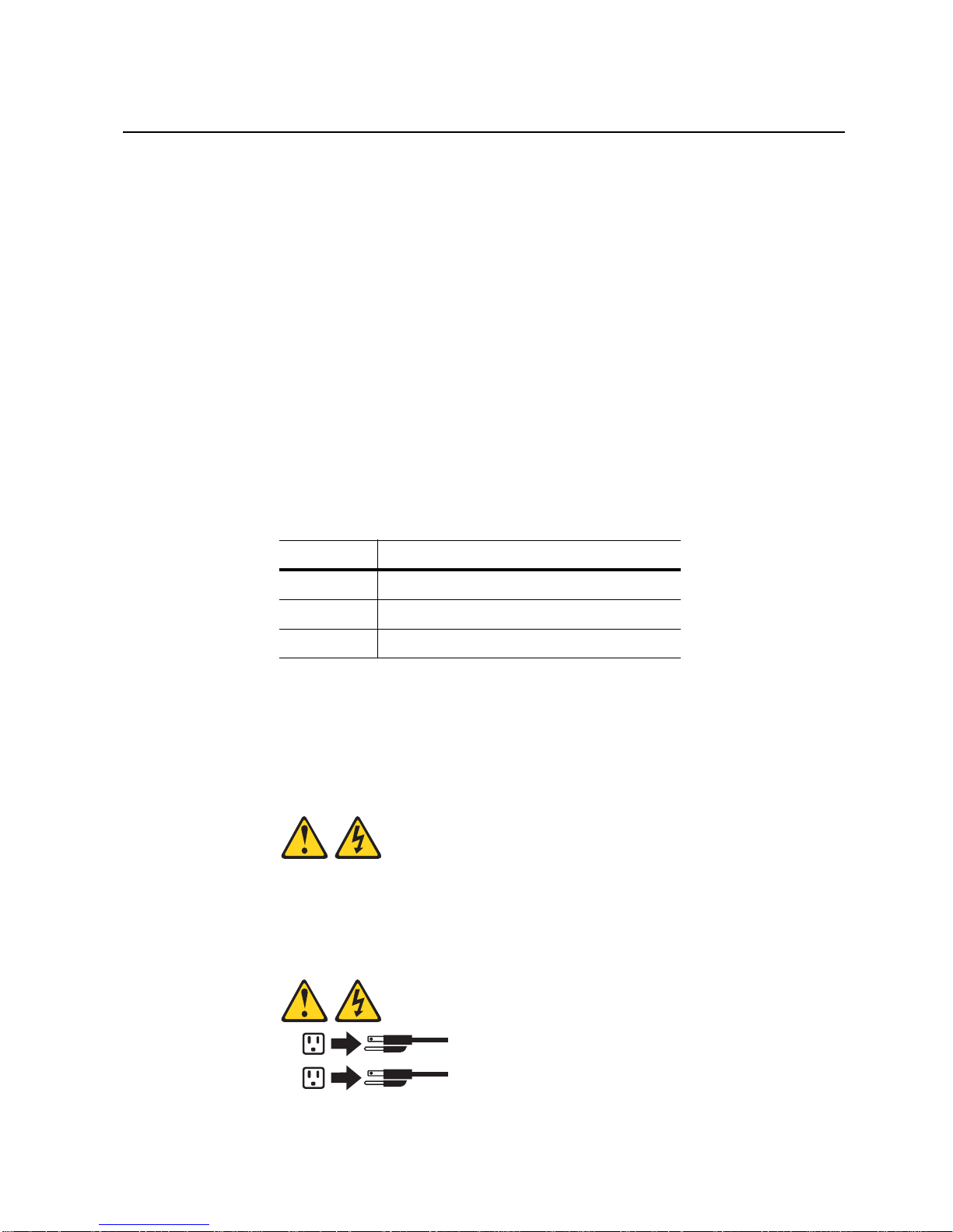
Statement 31
DANGER
Electrical current from power, telephone, and communication cables is
hazardous.
To avoid a shock hazard:
•
Do not connect or disconnect any cables or perform installation,
maintenance, or reconfiguration of this produ ct during an electrical storm.
•
Connect all power cords to a properly wired and grounded power source.
•
Connect to properly wired power sources any equipment that will be
attached to this product.
•
When possible, use one hand only to connect or disconnect signal cables.
•
Never turn on any equipment when there is evidence of fire, water, or
structural damage.
•
Disconnect the attached ac power cords, dc power sources, network
connections, telecommunications systems, and seria l cables before you
open the device covers, unless instructed otherwise in the installation
and configuration procedures.
•
Connect and disconnect cables as described in th e following table when
you install, move, or open covers on this product or attached devices.
To Connect:
1. Turn OFF all power sources and
equipment that is to be attached to
this product.
2. Attach signal cables to the product.
3. Attach power cords to the product.
– For ac systems, use appliance
inlets.
– For dc systems, ensure correct
polarity of -48 V dc connections:
RTN is + and -48 V dc is -. Earth
ground should use a two-hole
lug for safety.
4. Attach signal cables to other
devices.
5. Connect power cords to their
sources.
6. Turn ON all the power sources.
Two power supply modules are required for redundancy. Each power supply can be
connected to a separate circuit to mitigate the risk of down-time during a localized
power failure. When used in a redundant configuration, the dual power supplies
have a load-sharing capability that enables each power supply to operate at
approximately 50 percent of full load.
To Disconnect:
1. Turn OFF all power sources and
equipment that is to be attached to
this product.
– For ac systems, remove all
power cords from the chassis
power receptacles or interrupt
power at the ac power
distribution unit.
– For dc systems, disconnect dc
power sources at the breaker
panel or by turning off the power
source. Then, remove the dc
cables.
2. Remove the signal cables from the
connectors.
3. Remove all cables from the
devices.
26 RackSwitch G8052 Installation Guide
 Loading...