

Page 1

Lenovo IdeaPad
Flex 2-14/Flex 2-14D
Flex 2-15/Flex 2-15D
Hardware
Maintenance
Manual
Page 2

Note:
Before using this information and the product it supports, be sure to read the general information
under “Notices” on page 104.
First Edition (March 2014)
© Copyright Lenovo 2014. All rights reserved.
LENOVO products, data, computer software, and services have been developed exclusively at private
expense and are sold to governmental entities as commercial items as defined by 48 C.F.R. 2.101 with
limited and restricted rights to use, reproduction and disclosure.
LIMITED AND RESTRICTED RIGHTS NOTICE: If products, data, computer software, or services are
delivered pursuant a General Services Administration “GSA” contract, use, reproduction, or disclosure is subject to restrictions set forth in Contract No. GS-35F-05925.
© 2014 Lenovo
Page 3

Contents
About this manual........................................iv
Safety information......................................... 1
General safety ...................................................... 2
Electrical safety....................................................3
Safety inspection guide ...................................... 5
Handling devices that are sensitive to
electrostatic discharge......................................... 6
Grounding requirements ...................................6
Safety notices: multilingual translations.......... 7
Laser compliance statement............................. 14
Important service information ...................16
Strategy for replacing FRUs............................. 16
Strategy for replacing a hard disk
drive .............................................................. 17
Important notice for replacing a system
board ............................................................. 17
Important information about replacing RoHS
compliant FRUs................................................. 18
General checkout ........................................ 19
What to do first.................................................. 20
Power system checkout.................................... 21
Checking the AC adapter........................... 21
Checking operational charging................. 22
Checking the battery pack ......................... 22
Related service information ....................... 23
Restoring the factory contents by using
Recovery Disc Set..............................................23
Start Recovery Disc (one disc)................... 23
Operating System Recovery Disc (one or
more discs) ................................................... 23
Applications and Drivers Recovery Disc
(one or more discs)...................................... 23
Supplemental Recovery Disc..................... 23
Passwords........................................................... 24
Power-on password.................................... 24
Hard-disk password................................... 24
Supervisor password.................................. 24
Power management .......................................... 25
Screen blank state........................................ 25
Putting the computer to sleep or shutting it
down ............................................................. 25
Lenovo Flex 2-14/Flex 2-14D/Flex 2-15/Flex
2-15D ............................................................ 27
Specifications ..................................................... 27
Status indicators ................................................ 29
Hotkeys............................................................... 31
FRU replacement notices..................................32
Screw notices................................................32
Removing and replacing an FRU....................33
1010 Keyboard..............................................34
1020 Optical drive........................................36
1030 Hard disk drive(HDD)/Memory/
Mini PCI Express Card slot compartment
cover ..............................................................37
1040 Battery pack.........................................39
1050 Hard disk drive...................................40
1060 DIMM...................................................42
1070 PCI Express Mini Card for wireless
LAN/WAN ..................................................43
1080 Fan assembly and Heat Sink
assembly........................................................45
1090 System board.......................................49
1100 LCD unit...............................................53
1110 Speakers, base cover, IO board, DC-IN,
power board and ODD transfer board .....56
1120 LCD front bezel...................................64
1130 LCD panel, LCD cable and hinges ...66
1140 Integrated camera...............................68
1150 Antenna assembly and LCD cover...69
Locations.............................................................70
Front view.....................................................70
Bottom and Left-side view.........................72
Right-side view............................................73
Parts list...............................................................74
Overall...........................................................75
LCD FRUs.....................................................85
Keyboard.......................................................88
AC adapters................................................100
Screws..........................................................100
Power cords................................................101
Notices ....................................................... 104
Trademarks.......................................................105
iii
Page 4

About this manual
This manual contains service and reference information for the following
Lenovo product:
Lenovo Flex 2-14/Flex 2-14D/Flex 2-15/Flex 2-15D
Use this manual to troubleshoot problems.
The manual is divided into the following sections:
• The common sections provide general information, guidelines, and safety
information required for servicing computers.
• The product-specific section includes service, reference, and product-specific
parts information.
Important:
This manual is intended only for trained servicers who are familiar with
Lenovo products. Use this manual to troubleshoot problems effectively.
Before servicing a Lenovo product, make sure to read all the information
under “Safety information” on page 1 and “Important service information”
on page 16.
iv
Page 5

Safety information
This chapter presents the following safety information that you need to get
familiar with before you service a Lenovo computer:
• “General safety” on page 2
• “Electrical safety” on page 3
• “Safety inspection guide” on page 5
• “Handling devices that are sensitive to electrostatic discharge” on page 6
• “Grounding requirements” on page 6
• “Safety notices: multilingual translations” on page 7
• “Laser compliance statement” on page 14
Safety information
1
Page 6

Lenovo Flex 2-14/Flex 2-14D/Flex 2-15/Flex 2-15D Hardware Maintenance Manual
General safety
Follow these rules below to ensure general safety:
• Observe a good housekeeping in the area where the machines are put during
and after the maintenance.
• When lifting any heavy object:
1. Make sure that you can stand safely without slipping.
2. Distribute the weight of the object equally between your feet.
3. Use a slow lifting force. Never move suddenly or twist when you attempt
to lift it.
4. Lift it by standing or pushing up with your leg muscles; this action could
avoid the strain from the muscles in your back. Do not attempt to lift any
object that weighs more than 16 kg (35 lb) or that you think is too heavy for
you.
• Do not perform any action that causes hazards to the customer, or that makes
the machine unsafe.
• Before you start the machine, make sure that other service representatives
and the customer are not in a hazardous position.
• Please remove covers and other parts in a safe place, away from all
personnel, while you are servicing the machine.
• Keep your toolcase away from walk areas so that other people will not trip it
over.
• Do not wear loose clothing that can be trapped in the moving parts of the
machine. Make sure that your sleeves are fastened or rolled up above your
elbows. If your hair is long, fasten it.
• Insert the ends of your necktie or scarf inside clothing or fasten it with the
nonconductive clip, about 8 centimeters (3 inches) from the end.
• Do not wear jewelry, chains, metal-frame eyeglasses, or metal fasteners for
your clothing.
Attention: Metal objects are good electrical conductors.
• Wear safety glasses when you are hammering, drilling, soldering, cutting
wire, attaching springs, using solvents, or working in any other conditions
that may be hazardous to your eyes.
• After service, reinstall all safety shields, guards, labels, and ground wires.
Replace any safety device that is worn or defective.
• Reinstall all covers correctly before returning the machine to the customer.
• Fan louvers on the machine help to prevent the overheating of internal
components. Do not obstruct fan louvers or cover them with labels or
stickers.
2
Page 7
Electrical safety
Observe the following rules when working on electrical equipments.
Important:
Use only approved tools and test equipments. Some hand tools have
handles covered with a soft material that does not insulate you when
working with live electrical currents.
Many customers have rubber floor mats near their machines that contain
small conductive fibers to decrease electrostatic discharges. Do not use such
kind of mat to protect yourself from electrical shock.
• Find the room emergency power-off (EPO) switch, disconnecting switch, or
electrical outlet. If an electrical accident occurs, you can then operate the
switch or unplug the power cord quickly.
• Do not work alone under hazardous conditions or near the equipment that
has hazardous voltages.
• Disconnect all power before:
– Performing a mechanical inspection
– Working near power supplies
– Removing or installing main units
• Before you start to work on the machine, unplug the power cord. If you
cannot unplug it, ask the customer to power-off the wall box that supplies
power to the machine, and to lock the wall box in the off position.
• If you need to work on a machine that has exposed electrical circuits, observe
the following precautions:
– Ensure that another person, familiar with the power-off controls, is near
– Use only one hand when working with powered-on electrical equipment;
– When using testers, set the controls correctly and use the approved probe
– Stand on suitable rubber mats (obtained locally, if necessary) to insulate
Observe the special safety precautions when you work with very high voltages;
instructions for these precautions are in the safety sections of maintenance
information. Be extremely careful when you measure the high voltages.
• Regularly inspect and maintain your electrical hand tools for safe operational
condition.
• Do not use worn or broken tools and testers.
• Never assume that power has been disconnected from a circuit. First, check it
to make sure that it has been powered off.
Safety information
you.
Attention: Another person must be there to switch off the power, if
necessary.
keep the other hand in your pocket or behind your back.
Attention: An electrical shock can occur only when there is a complete
circuit. By observing the above rule, you may prevent a current from
passing through your body.
leads and accessories for that tester.
you from grounds such as metal floor strips and machine frames.
3
Page 8

Lenovo Flex 2-14/Flex 2-14D/Flex 2-15/Flex 2-15D Hardware Maintenance Manual
• Always look carefully for possible hazards in your work area. Examples of
these hazards are moist floors, nongrounded power extension cables, power
surges, and missing safety grounds.
• Do not touch live electrical circuits with the reflective surface of a plastic
dental mirror. The surface is conductive; such touching can cause personal
injury and machine damage.
• Do not service the following parts with the power on when they are removed
from their normal operating places in a machine:
– Power supply units
–Pumps
–Blowers and fans
– Motor generators
and similar units. (This practice ensures correct grounding of the units.)
• If an electrical accident occurs:
– Use caution: do not become a victim yourself.
–Switch off the power.
– Send the victim to get medical aid.
4
Page 9

Safety inspection guide
The purpose of this inspection guide is to assist you in identifying potential
unsafe conditions. As each machine was designed and built, required safety
items were installed to protect users and service personnel from injury. This
guide addresses only those items. You should use good judgment to identify
potential safety hazards du e to attachment of non-Lenovo features or options not
covered by this inspection guide.
If any unsafe conditions are present, you must determine how serious the
apparent hazard could be and whether you can continue without first correcting
the problem.
Consider these conditions and the safety hazards they present:
• Electrical hazards, especially primary power (primary voltage on the frame
can cause serious or fatal electrical shock)
• Explosive hazards, such as a damaged CRT face or a bulging capacitor
• Mechanical hazards, such as loose or missing hardware
To determine whether there are any potential unsafe conditions, use the
following checklist at the beginning of every service task. Begin the checks with
the power off, and the power cord disconnected.
Checklist:
1. Check exterior covers for damage (loose, broken, or sharp edges).
2. Turn off the computer. Disconnect the power cord.
3. Check the power cord for:
a. A third-wire ground connector in good condition. Use a meter to measure
third-wire ground continuity for 0.1 ohm or less between the external
ground pin and the frame ground.
b. The power cord should be the type specified in the parts list.
c. Insulation must not be frayed or worn.
4. Check for cracked or bulging batteries.
5. Remove the cover.
6. Check for any obvious non-Lenovo alterations. Use good judgment as to the
safety of any non-Lenovo alterations.
7. Check inside the unit for a ny obvious unsafe conditions, such as metal filin gs,
contamination, water or other liquids, or signs of fire or smoke damage.
8. Check for worn, frayed, or pinched cables.
9. Check that the power-supply cover fasteners (screws or rivets) have not been
removed or tampered with.
Safety information
5
Page 10
Lenovo Flex 2-14/Flex 2-14D/Flex 2-15/Flex 2-15D Hardware Maintenance Manual
Handling devices that are sensitive to electrostatic discharge
Any computer part containing transistors or integrated circuits (ICs) should be
considered sensitive to electrostatic discharge (ESD). ESD damage can occur
when there is a difference in charge between objects. Protect against ESD damage
by equalizing the charge so that the machine, the part, the work mat, and the
person handling the part are all at the same charge.
Notes:
1. Use product-specific ESD procedures when they exceed the
requirements noted here.
2. Make sure that the ESD protective devices you use have been certified
(ISO 9000) as fully effective.
When handling ESD-sensitive parts:
• Keep the parts in protective packages until they are inserted into the product.
• Avoid contact with other people.
• Wear a grounded wrist strap against your skin to eliminate static on your
body.
• Prevent the part from touching your clothing. Most clothing is insulative and
retains a charge even when you are wearing a wrist strap.
• Use the black side of a grounded work mat to provide a static-free work
surface. The mat is especially useful when handling ESD-sensitive devices.
• Select a grounding system, such as those listed below, to provide protection
that meets the specific service requirement.
Notes:
The use of a grounding system to guard against ES D damage is desirable but
not necessary.
– Attach the ESD ground clip to any frame ground, ground braid, or green-
wire ground.
– When working on a double-insulated or battery-operated system, use an
ESD common ground or reference point. You can use coax or connectoroutside shells on these systems.
– Use the round ground prong of the ac plug on ac-operated computers.
Grounding requirements
Electrical grounding of the computer is required for operator safety and correct
system function. Proper grounding of the electrical outlet can be verified by a
certified electrician.
6
Page 11
Safety notices: multilingual translations
The safety notices in this section are provided in English, French, German,
Hebrew, Italian, Japanese, and Spanish.
Safety notice 1
Before the computer is powered on after FRU replacement, make sure all
screws, springs, and other small parts are in place and are not left loose
inside the computer. Verify this by shaking the computer and listening for
rattling sounds. Metallic parts or metal flakes can cause electrical shorts.
Avant de remettre l’ord inateur sous tension après remplacement d’u ne unité
en clientèle, vérifiez que tous les ressorts, vis et autres pièces sont bien en
place et bien fixées. Pour ce faire, secouez l’unité et assurez-vous qu’aucun
bruit suspect ne se produit. Des pièces métalliques ou des copeaux de métal
pourraient causer un court-circuit.
Bevor nach einem FRU-Austausch der Computer wieder angeschlossen
wird, muß sichergestellt werden, daß keine Schrauben, Federn oder andere
Kleinteile fehlen oder im Gehäuse vergessen wurden. Der Computer muß
geschüttelt und auf Klappergeräusche geprüft werden. Metallteile odersplitter können Kurzschlüsse erzeugen.
Prima di accendere l’elaboratore dopo che é stata effettuata la sostituzione di
una FRU, accertarsi che tutte le viti, le molle e tutte le altri parti di piccole
dimensioni siano nella corretta posizione e non siano sparse all’interno
dell’elaboratore. Verificare ciò scuotendo l’elaboratore e prestando
attenzione ad eventuali rumori; eventuali parti o pezzetti metallici possono
provocare cortocircuiti pericolosi.
Safety information
Antes de encender el sistema despues de sustituir una FRU, compruebe que
todos los tornillos, muelles y demás piezas pequeñas se encuentran en su
sitio y no se encuentran sueltas dentro del sistema. Compruébelo agitando el
sistema y escuchando los posibles ruidos que provocarían. Las piezas
metálicas pueden causar cortocircuitos eléctricos.
7
Page 12
Lenovo Flex 2-14/Flex 2-14D/Flex 2-15/Flex 2-15D Hardware Maintenance Manual
Safety notice 2
DANGER
Some standby batteries contain a small amount of nickel and cadmium. Do
not disassemble a standby battery, recharge it, throw it into fire or water, or
short-circuit it. Dispose of the battery as required by local ordinances or
regulations. Use only the battery in the appropriate parts listing. Use of an
incorrect battery can result in ignition or explosion of the battery.
Certaines batteries de secours contiennent du nickel et du cadmium. Ne les
démontez pas, ne les rechargez pas, ne les exposez ni au feu ni à l’eau. Ne
les mettez pas en court-circuit. Pour les mettre au rebut, conformez-vous à
la réglementation en vigueur. Lorsque vous remplacez la pile de sauvegarde
ou celle de l’horloge temps r éel, veillez à n’utiliser que les modèles cités dans
la liste de pièces détachées adéquate. Une batterie ou une pile inappropriée
risque de prendre feu ou d’exploser.
Die Bereitschaftsbatterie, die sich unter dem Diskettenlaufwerk befindet,
kann geringe Mengen Nickel und Cadmium enthalten. Sie darf nicht
zerlegt, wiederaufgeladen, kurzgeschlossen, oder Feuer oder Wasser
ausgesetzt werden. Bei der Entsorgung die örtlichen Bestimmungen für
Sondermüll beachten. Beim Ersetzen der Bereitschafts-oder Systembatterie
nur Batterien des Typs verwenden, der in der Ersatzteilliste aufgeführt ist.
Der Einsatz falscher Batterien kann zu Entzündung oder Explosion führen.
Alcune batterie di riserva contengono una piccola quantità di nichel e
cadmio. Non smontarle, ricaricarle, gettarle nel fuoco o nell’acqua né
cortocircuitarle. Smaltirle secondo la normativa in vigore (DPR 915/82,
successive disposizioni e disposizioni locali). Quando si sostituisce la
batteria dell’RTC (real time clock) o la batteria di supporto, utilizzare
soltanto i tipi inseriti nell’appropriato Catalogo parti. L’impiego di una
batteria non adatta potrebbe determinare l’incendio o l’esplosione della
batteria stessa.
Algunas baterías de reserva contienen una pequeña cantidad de níquel y
cadmio. No las desmonte, ni recargue, ni las eche al fuego o al agua ni las
cortocircuite. Deséchelas tal como dispone la normativa local. Utilice sólo
baterías que se encuentren en la lista de piezas. La utilización de una batería
no apropiada puede provocar la ignición o explosión de la misma.
8
Page 13
Safety information
Safety notice 3
DANGER
The battery pack contains small amounts of nickel. Do not disassemble it,
throw it into fire or water, or short-circuit it. Dispose of the battery pack as
required by local ordinances or regulations. Use only the battery in the
appropriate parts listing when replacing the battery pack. Use of an
incorrect battery can result in ignition or explosion of the battery.
La batterie contient du nickel. Ne la démontez pas, ne l’exposez ni au feu ni
à l’eau. Ne la mettez pas en court-circuit. Pour la mettre au rebut,
conformez-vous à la réglementation en vigueur. Lorsque vous remplacez la
batterie, veillez à n’utiliser que les modèles cités dans la liste de pièces
détachées adéquate. En effet, une batterie inappropriée risque de prendre
feu ou d’exploser.
Akkus enthalten geringe Mengen von Nickel. Sie dürfen nicht zerlegt,
wiederaufgeladen, kurzgeschlossen, oder Feuer oder Wasser ausgesetzt
werden. Bei der Entsorgung die örtlichen Bestimmungen für Sondermüll
beachten. Beim Ersetzen der Batterie nur Batterien des Typs verwenden, der
in der Ersatzteilliste aufgeführt ist. Der Einsatz falscher Batterien kann zu
Entzündung oder Explosion führen.
La batteria contiene piccole quantità di nichel. Non smontarla, gettarla nel
fuoco o nell’acqua né cortocircuitarla. Smaltirla secondo la normativa in
vigore (DPR 915/82, successive disposizioni e disposizioni locali). Quando
si sostituisce la batteria, utilizzare soltanto i tipi inseriti nell’appropriato
Catalogo parti. L’impiego di una batteria non adatta potrebbe determinare
l’incendio o l’esplosione della batteria stessa.
Las baterías contienen pequeñas cantidades de níquel. No las desmonte, ni
recargue, ni las eche al fuego o al agua ni las cortocircuite. Deséchelas tal
como dispone la normativa local. Utilice sólo baterías que se encuentren en
la lista de piezas al sustituir la batería. La utilización de una batería no
apropiada puede provocar la ignición o explosión de la misma.
9
Page 14
Lenovo Flex 2-14/Flex 2-14D/Flex 2-15/Flex 2-15D Hardware Maintenance Manual
Safety notice 4
DANGER
The lithium battery can cause a fire, an explosion, or a severe burn. Do not
recharge it, remove its polarized connector, disassemble it, heat it above
100°C (212°F), incinerate it, or expose its cell contents to water. Dispose of
the battery as required by local ordinances or regulations. Use only the
battery in the appropriate parts listing. Use of an incorrect battery can result
in ignition or explosion of the battery.
La pile de sauvegarde contient du lithium. Elle présente des risques
d’incendie, d’explosion ou de brûlures graves. Ne la rechargez pas, ne
retirez pas son connecteur polarisé et ne la démontez pas. Ne l’exposez pas
à une temperature supérieure à 100°C, ne la faites pas brûler et n’en exposez
pas le contenu à l’eau. Mettez la pile au rebut conformément à la
réglementation en vigueur. Une pile inappropriée risque de prendre feu ou
d’exploser.
Die Systembatterie ist eine Lithiumbatterie. Sie kann sich entzünden,
explodieren oder schwere Verbrennungen hervorrufen. Batterien dieses
Typs dürfen nicht aufgeladen, zerlegt, über 100 C erhitzt oder verbrannt
werden. Auch darf ihr Inhalt nicht mit Wasser in Verbindung gebracht oder
der zur richtigen Polung angebrachte Verbindungsstecker entfernt werden.
Bei der Entsorgung die örtlichen Bestimmungen für Sondermüll beachten.
Beim Ersetzen der Batterie nur Batterien des Typs verwenden, der in der
Ersatzteilliste aufgeführt ist. Der Einsatz falscher Batterien kann zu
Entzündung oder Explosion führen.
10
La batteria di supporto e una batteria al litio e puo incendiarsi, esplodere o
procurare gravi ustioni. Evitare di ricaricarla, smontarne il connettore
polarizzato, smontarla, riscaldarla ad una temperatura superiore ai 100
gradi centigradi, incendiarla o gettarla in acqua. Smaltirla secondo la
normativa in vigore (DPR 915/82, successive disposizioni e disposizioni
locali). L’impiego di una batteria non adatta potrebbe determinare
l’incendio o l’esplosione della batteria stessa.
La batería de repuesto es una batería de litio y puede provocar incendios,
explosiones o quemaduras graves. No la recargue, ni quite el conector
polarizado, ni la desmonte, ni caliente por encima de los 100°C (212°F), ni la
incinere ni exponga el contenido de sus celdas al agua. Deséchela tal como
dispone la normativa local.
Page 15

Safety information
Safety notice 5
If the LCD breaks and the fluid from inside the LCD gets into your eyes or
on your hands, immediately wash the affected areas with water at least for
15 minutes. Seek medical care if any symptoms caused by the fluid are
present after washing.
Si le panneau d’affichage à cristaux liquides se brise et que vous recevez dans
les yeux ou sur les mains une partie du fluide, rincez-les abondamment
pendant au moins quinze minutes. Consultez un médecin si des symptômes
persistent après le lavage.
Die Leuchtstoffröhre im LCD-Bildschirm enthält Quecksilber. Bei der
Entsorgung die örtlichen Bestimmungen für Sondermüll beachten. Der
LCD-Bildschirm besteht aus Glas und kann zerbrechen, wenn er
unsachgemäß behandelt wird oder der Computer auf den Boden fällt. Wenn
der Bildschirm beschädigt ist und die darin befindliche Flüssigkeit in
Kontakt mit Haut und Augen gerät, sollten die betroffenen Stellen
mindestens 15 Minuten mit Wasser abgespült und bei Beschwerden
anschließend ein Arzt aufgesucht werden.
Nel caso che caso l’LCD si dovesse rompere ed il liquido in esso contenuto
entrasse in contatto con gli occhi o le mani, lavare immediatamente le parti
interessate con acqua corrente per almeno 15 minuti; poi consultare un
medico se i sintomi dovessero permanere.
Si la LCD se rompe y el fluido de su interior entra en contacto con sus ojos o
sus manos, lave inmediatamente las áreas afectadas con agua durante
15 minutos como mínimo. Obtenga atención medica si se presenta algún
síntoma del fluido despues de lavarse.
11
Page 16
Lenovo Flex 2-14/Flex 2-14D/Flex 2-15/Flex 2-15D Hardware Maintenance Manual
Safety notice 6
DANGER
To avoid shock, do not remove the plastic cover that protects the lower part
of the inverter card.
Afin d’éviter tout risque de choc électrique, ne retirez pas le cache en
plastique protégeant la partie inférieure de la carte d’alimentation.
Aus Sicherheitsgründen die Kunststoffabdeckung, die den unteren Teil der
Spannungswandlerplatine umgibt, nicht entfernen.
Per evitare scosse elettriche, non rimuovere la copertura in plastica che
avvolge la parte inferiore della scheda invertitore.
Para evitar descargas, no quite la cubierta de plástico que rodea la parte baja
de la tarjeta invertida.
Safety notice 7
DANGER
Though the main batteries have low voltage, a shorted or grounded battery
can produce enough current to burn personnel or combustible materials.
Bien que le voltage des batteries principales soit peu élevé, le court-circuit ou
la mise à la masse d’une batterie peut produire suffisamment de courant
pour brûler des matériaux combustibles ou causer des brûlures corporelles
graves.
Obwohl Hauptbatterien eine niedrige Spannung haben, können sie doch bei
Kurzschluß oder Erdung genug Strom abgeben, um brennbare Materialien
zu entzünden oder Verletzungen bei Personen hervorzurufen.
12
Sebbene le batterie di alimentazione siano a basso voltaggio, una batteria in
corto circuito o a massa può fornire corrente sufficiente da bruciare materiali
combustibili o provocare ustioni ai tecnici di manutenzione.
Aunque las baterías principales tienen un voltaje bajo, una batería
cortocircuitada o con contacto a tierra puede producir la corriente suficiente
como para quemar material combustible o provocar quemaduras en el
personal.
Page 17
Safety information
Safety notice 8
DANGER
Before removing any FRU, turn off the computer, unplug all power cords
from electrical outlets, remove the battery pack, and then disconnect any
interconnecting cables.
Avant de retirer une unité remplaçable en clientèle, mettez le système hors
tension, débranchez tous les cordons d’alimentation des socles de prise de
courant, retirez la batterie et déconnectez tous les cordons d’interface.
Die Stromzufuhr muß abgeschaltet, alle Stromkabel aus der Steckdose
gezogen, der Akku entfernt und alle Verbindungskabel abgenommen sein,
bevor eine FRU entfernt wird.
Prima di rimuovere qualsiasi FR U, spegnere il sistema, scollegare dalle prese
elettriche tutti i cavi di alimentazione, rimuovere la batteria e poi scollegare
i cavi di interconnessione.
Antes de quitar una FRU, apague el sistema, desenchufe todos los cables de
las tomas de corriente eléctrica, quite la batería y, a continuación, desconecte
cualquier cable de conexión entre dispositivos.
13
Page 18
Lenovo Flex 2-14/Flex 2-14D/Flex 2-15/Flex 2-15D Hardware Maintenance Manual
Laser compliance statement
Some models of Lenovo computer are equipped from the factory with an optical
storage device such as a CD-ROM drive or a DVD-ROM drive. Such devices are
also sold separately as options. If one of these drives is installed, it is certified in
the U.S. to conform to the requirements of the Department of Health and Human
Services 21 Code of Federal Regulations (DHHS 21 CFR) Subchapter J for Class
1 laser products. Elsewhere, the drive is certified to conform to the requirements
of the International Electrotechnical Commission (IEC) 825 and C ENELEC EN 60
825 for Class 1 laser products.
If a CD-ROM drive, a DVD-ROM drive, or another laser device is installed, note
the following:
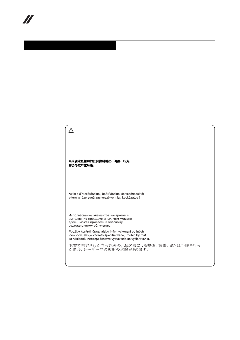
CAUTION
Use of controls or adjustments or performance of procedures other than
those specified herein might result in hazardous radiation exposure.
O uso de controles, ajustes ou desempenho de procedimentos diferentes
daqueles aqui especificados pode resultar em perigosa exposição à radiação.
Pour éviter tout risque d’exposition au rayon laser, respectez les consignes
de réglage et d’utilisation des commandes, ainsi que les procédures décrites.
Werden Steuer- und Einstellelemente anders als hier festgesetzt verwendet,
kann gefährliche Laserstrahlung auftreten.
14
L’utilizzo di controlli, regolazioni o l’esecuzione di procedure diverse da
quelle specificate possono provocare l’esposizione a.
El uso de controles o ajustes o la ejecución de procedimientos distintos de los
aquí especificados puede provocar la exposición a radiaciones peligrosas.
Opening the CD-ROM drive, the DVD-ROM drive, or any other optical storage
device could result in exposure to hazardous laser radiation. There are no
serviceable parts inside those drives. Do not open.
Page 19
Safety information
A CD-ROM drive, a DVD-ROM drive, or any other storage device installed may
contain an embedded Class 3A or Class 3B laser diode. Note the following:
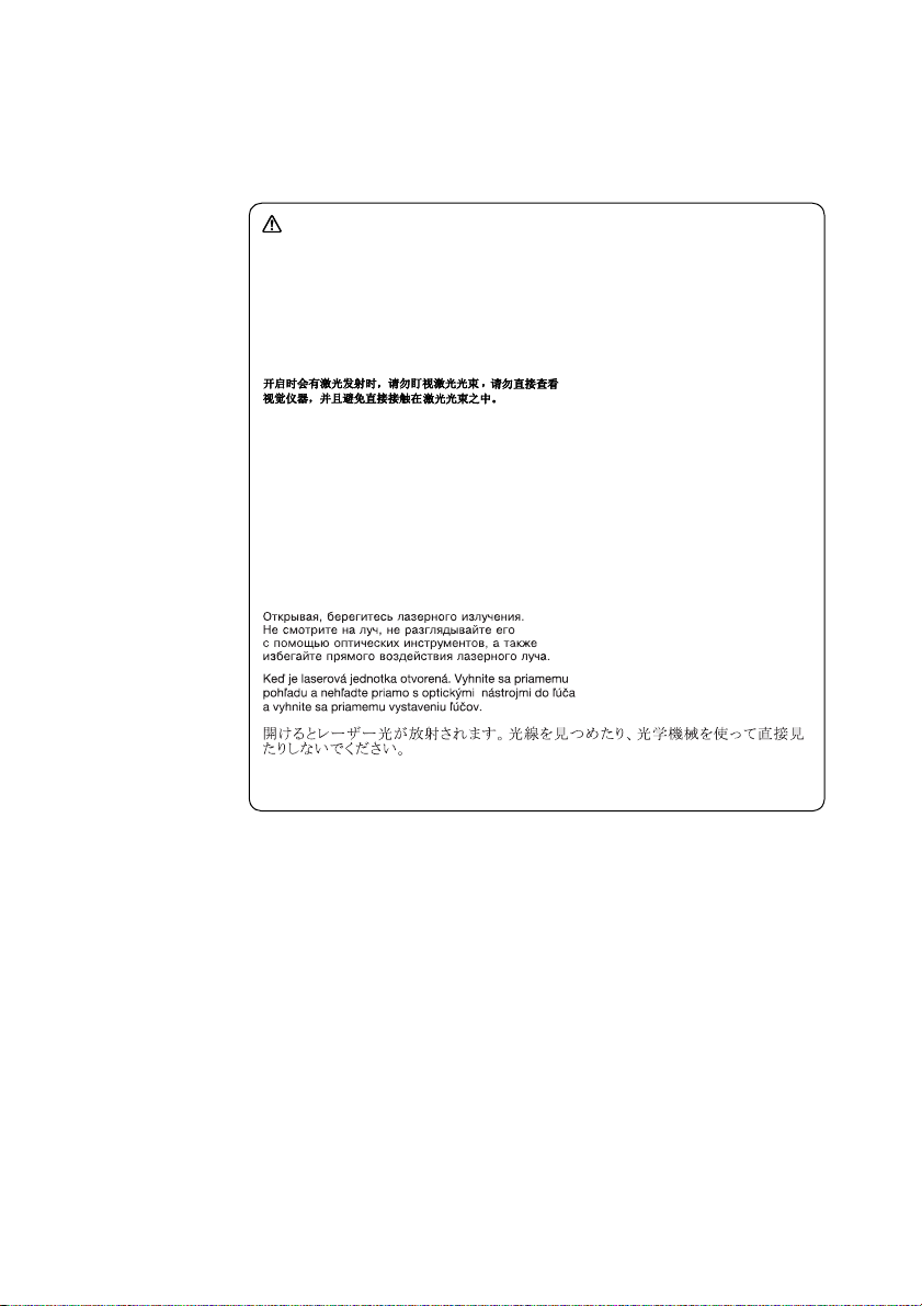
DANGER
Emits visible and invisible laser radiation when open. Do not stare into the
beam, do not view directly with optical instruments, and avoid direct
exposure to the beam.
Radiação por raio laser ao abrir. Não olhe fixo no feixe de luz, não olhe
diretamente por meio de instrumentos óticos e evite exposição direta com o
feixe de luz.
Rayonnement laser si carter ouvert. Évitez de fixer le faisceau, de le regarder
directement avec des instruments optiques, ou de vous exposer au rayon.
Laserstrahlung bei geöffnetem Gerät. Nicht direkt oder über optische
Instrumente in den Laserstrahl sehen und den Strahlungsbereich meiden.
Kinyitáskor lézersugár ! Ne nézzen bele se szabad szemmel, se optikai
eszközökkel. Kerülje a sugárnyalábbal való érintkezést!
Aprendo l’unità vengono emesse radiazioni laser. Non fissare il fascio, non
guardarlo direttamente con strumenti ottici e evitare l’esposizione diretta al
fascio.
Radiación láser al abrir. No mire fijamente ni examine con instrumental
óptico el haz de luz. Evite la exposición directa al haz.
15
Page 20
Lenovo Flex 2-14/Flex 2-14D/Flex 2-15/Flex 2-15D Hardware Maintenance Manual
Important service information
This chapter presents the following important service information:
• “Strategy for replacing FRUs” on page 16
– “Strategy for replacing a hard disk drive” on page 17
– “Important notice for replacing a system board” on page 17
• “Important information about replacing RoHS compliant FRUs” on page 18
Important:
BIOS and device driver fixes are customer-installable. The BIOS and device
drivers are posted on the customer support site:
http://support.lenovo.com
Strategy for replacing FRUs
Before replacing parts:
Make sure that all software fixes, drivers, and BIOS downloads are installed
before replacing any FRUs listed in this manual.
After a system board is replaced, ensure that the latest BIOS is loaded to the
system board before completing the service action.
To download software fixes, drivers, and BIOS, follow the steps below:
1. Go to http://support.lenovo.com
2. Enter the serial number or select a product or use Lenovo smart
downloading.
3. Select the BIOS/Driver/Applications and download.
4. Follow the directions on the screen and install the necessary software.
.
.
16
Page 21

Important service information
Use the following strategy to prevent unnecessary expense for replacing and
servicing FRUs:
• If you are instructed to replace an FRU, but the replacement does not solve
the problem, reinstall the original FRU before you continue.
• Some computers have both a processor board and a system board. If you are
instructed to replace either of them, and replacing one of them does not solve
the problem, reinstall that board, and then replace the other one.
• If an adapter or a device consists of more than one FRU, any of the FRUs may
be the cause of the error. Before replacing the adapter or device, remove the
FRUs one by one to see if the symptoms change. Replace only the FRU that
changed the symptoms.
Attention: The setup configuration on the computer you are servicing may have
been customized. Running Automatic Configuration may alter the settings. No te
the current configuration settings (using the View Configuration option); then,
when service has been completed, verify that those settings remain in effect.
Strategy for replacing a hard disk drive
Always try to run a low-level format before replacing a hard disk drive. This will
cause all customer data on the hard disk to be lost. Make sure that the customer
has a current backup of the data before performing this action.
Attention: The drive startup sequence in the computer you are servicing may
have been changed. Be extremely careful during write operations such as
cop ying, sa ving, or formatt ing. I f you select a n incorr ect dr ive, data or p rogra ms
can be overwritten.
Important notice for replacing a system board
Some components mounted on a system board are very sensitive. Improper
handling can cause damage to those components, and may cause a system
malfunction.
Attention: When handling a system board:
• Do not drop the system board or apply any excessive force to it.
• Avoid rough handling of any kind.
• Avoid bending the system board and hard pushing to prevent cracking at
each BGA (Ball Grid Array) chipset.
17
Page 22
Lenovo Flex 2-14/Flex 2-14D/Flex 2-15/Flex 2-15D Hardware Maintenance Manual
Important information about replacing RoHS compliant FRUs
RoHS, The Restriction of Hazardous Substances in Electrical and
Electronic Equipment Directive (2002/95/EC) is a European Union legal
requirement affecting the global electronics industry. RoHS requirements
must be implemented on Lenovo products placed on the market after June
2006. Products on the market before June 2006 are not required to have
RoHS compliant parts. If the original FRU parts are non-compliant,
replacement parts can also be non-compliant. In all cases if the original
FRU parts are RoHS compliant, the replacement part must also be RoHS
compliant.
Note: RoHS and non -RoHS FRU part number s with the same fit and fu nction are
identified with unique FRU part numbers.
Lenovo plans to tr ansit to RoHS compliance well b efore the implementation date
and expects its suppliers to be ready to support Lenovo’s requirements and
schedule in the EU. Products sold in 2005 and 2006 will contain some RoHS
compliant FRUs. The following statement pertains to these products and any
product Lenovo produces containing RoHS compliant FRUs.
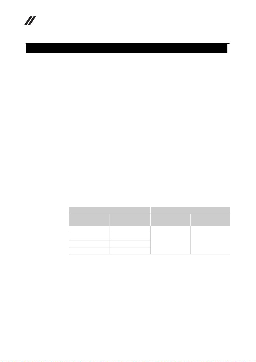
RoH S complian t FRUs have unique FRU part numbers. B efore or afte r the R oHS
implementation date, faile d RoHS compliant parts must always be repla ced with
RoHS compliant ones, so only the FRUs identified as compliant in the system
HMM or direct substitutions for those FRUs may be used.
18
Products marketed before June 2006 Products marketed after June 2006
Current or
original part
Non-RoHS Can be Non-RoHS
Non-RoHS Can be RoHS
Non-RoHS Can sub to RoHS
RoHS Must be RoHS
Note: A direct substitution is a part with a different FRU part number that is
automatically shipped by the distribution center at the time of the order.
Replacement
FRU
Current or
original part
Must be RoHS Must be RoHS
Replacement
FRU
Page 23

General checkout
This chapter presents the following information:
• “What to do first” on page 20
• “Power system checkout” on page 21
Before you go to the checkout, make sure to read the following important notes:
Important notes:
• Only certified trained personnel can service the computer.
• Before replacing any FRU, read the entire page on removing and
replacing FRUs.
• When you replace FRUs, use new nylon-coated screws.
• Be extremely careful during such write operations as copying,
saving, or formatting. Drives in the computer that you are servicing
sequence might have been altered. If you select an incorrect drive, data
or programs might be overwritten.
• Replace an FRU only with another FRU of the correct model. When
you replace an FRU, make sure that the machine model and the FRU part
number are correct by referring to the FRU parts list.
• An FRU should not be replaced just because of a single,
unreproducible failure. Single failures can occur for a variety of reasons
that have n othing t o do with a hard ware d efect , such as co smic radia tion,
electrostatic discharge, or software errors. Consider replacing an FRU
only when a problem recurs. If you suspect that an FRU is defective,
clear the error logs and run the test again. If the error does not recur, do
not replace the FRU.
• Be careful not to replace a nondefective FRU.
General checkout
19
Page 24

Lenovo Flex 2-14/Flex 2-14D/Flex 2-15/Flex 2-15D Hardware Maintenance Manual
What to do first
When you do return an FRU, you must include the following information in the
parts exchange form or parts return form that you attach to it:
1. Name and phone number of servicer
2. Date of service
3. Date on which the machine failed
4. Date of purchase
5. Procedure index and page number in which the failing FRU was detected
6. Failing FRU name and part number
7. Machine type, model number, and serial number
8. Customer’s name and address
Note for warranty: During the warranty period, the customer may be
responsible for repair costs if the computer damage was caused by misuse,
accident, modification, unsuitable physical or operating environment, or
improper maintenance by the customer.
The following is a list of some common items that are not covered under
warranty and some symptoms that might indicate that the system was subjected
to stress beyond normal use.
Before checking problems with the computer, determine whether the damage is
covered under the warranty by referring to the following list:
The following are not covered under warranty:
• LCD panel cracked from the application of excessive force or from being
dropped
• Scratched (cosmetic) parts
• Distortion, deformation, or discoloration of the cosmetic parts
• Plastic parts, latches, pins, or connectors that have been cracked or broken by
excessive force
• Damage caused by liquid spilled into the system
• Damage caused by the improper insertion of a PC Card or the installation of
an incompatible card
• Improper disk insertion or use of an optical drive
• Diskette drive damage caused by pressure on the diskette drive cover, foreign
material in the drive, or the insertion of a diskette with multiple labels
• Damaged or bent diskette eject button
• Fuses blown by attachment of a nonsupported device
• Forgotten computer password (making the computer unusable)
• Sticky keys caused by spilling a liquid onto the keyboard
• Use of an incorrect AC adapter on laptop products
20
The following symptoms might indicate damage caused by nonwarranted
activities:
• Missing parts might be a symptom of unauthorized service or modification.
• If the spindle of a hard disk drive becomes noisy, it may have been subjected
to excessive force, or dropped.
Page 25
Power system checkout
To verify a symptom, follow the steps below:
1. Turn off the computer.
2. Remove the battery pack.
3. Connect the AC adapter.
4. Make sure that power is supplied when you turn on the computer.
5. Turn off the computer.
6. Disconnect the AC adapter and install the charged battery pack.
7. Make sure that the battery pack supplies power when you turn on the
computer.
If you suspect a power problem, see the appropriate one of the following power
supply checkouts:
• “Checking the AC adapter” on page 21
• “Checking operational charging” on page 22
• “Checking the battery pack” on page 22
Checking the AC adapter
You are here because the computer fails only when the AC adapter is used.
• If the power-on indicator does not turn on, check the power cord of the AC
adapter for correct continuity and installation.
• If the computer does not charge during operation, go to “Checking
operational charging”.
To check the AC adapter, follow the steps below:
1. Unplug the AC adapter cable from the computer.
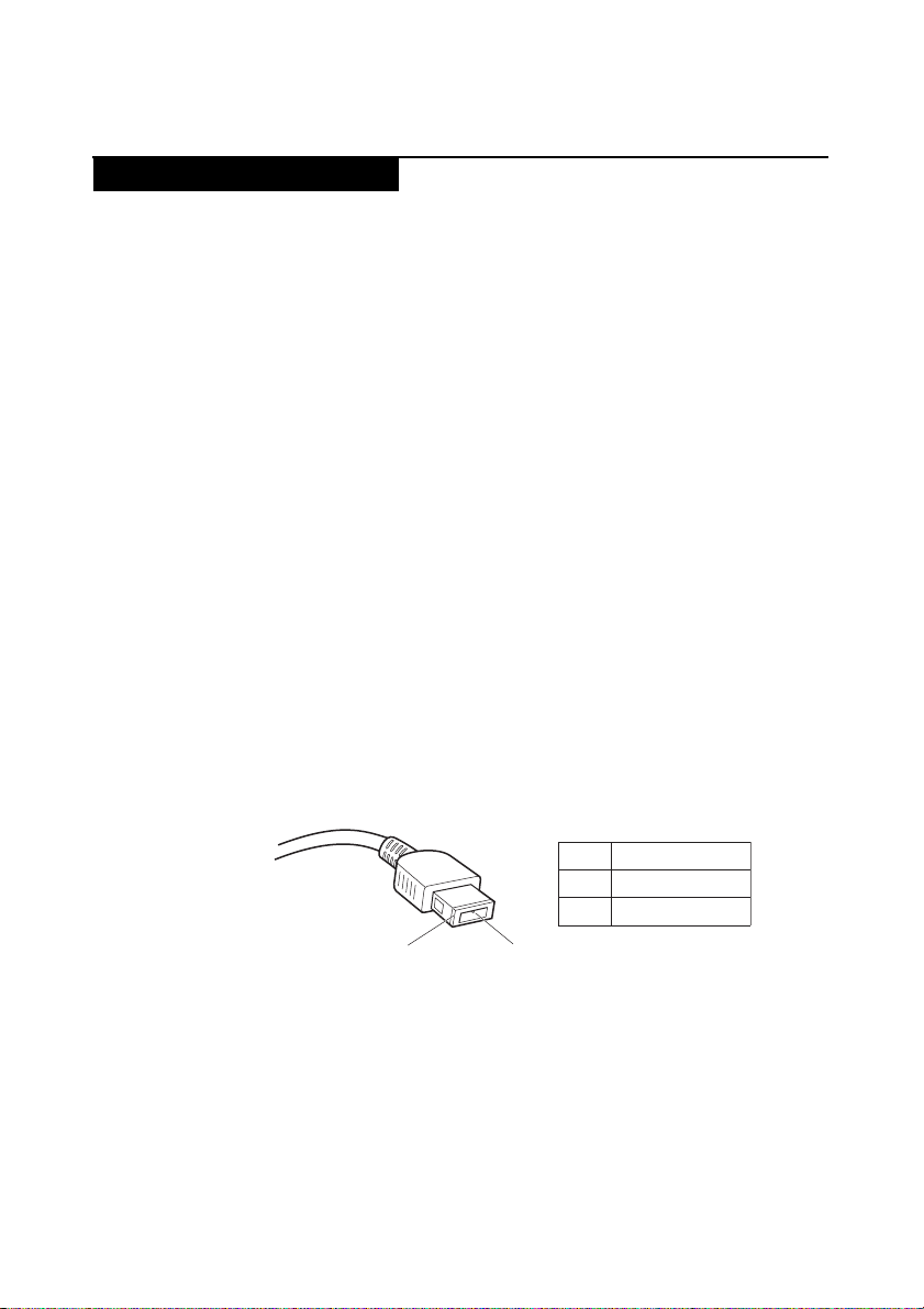
2. Measure the output voltage at the plug of the AC adapter cable. See the
following figure:
General checkout
Voltage (V DC)
Pin
1
2
2
Note: Output voltage for the AC adapter pin No. 2 may differ from the one you
are servicing.
3. If the voltage is not correct, replace the AC adapter.
4. If the voltage is acceptable, do the following:
• Replace the system board.
• If the problem persists, go to “Lenovo Flex 2-14/Flex 2-14D/Flex 2-15/Flex 215D” on page 27.
Note: Noise from the AC adapter does not always indicate a defect.
1
+20
0
21
Page 26

Lenovo Flex 2-14/Flex 2-14D/Flex 2-15/Flex 2-15D Hardware Maintenance Manual
Checking operational charging
To check whether the battery charges properly during operation, use a
discharged battery pack or a battery pack that has less than 50% of the total
power remaining when installed in the computer.
Perform operational charging. If the battery status indicator or icon does not
light on, remove the battery pack and let it return to room temperature. Reinstall
the battery pack. If the charge indicator or icon is still off, replace the battery
pack.
If the charge indicator still does not light on, replace the system board. Then
reinstall the battery pack. If it is still not charged, go to the next section.
Checking the battery pack
Battery charging does not start until the Power Meter shows that less than 95%
of the total power remains; under this condition the battery pack can charge to
100% of its capacity. This protects the battery pack from being overcharged or
from having a shortened life.
To check your battery, move your cursor to the Power Meter icon in the icon tray
of the Windows
percentage of battery power remaining is displayed. To get detailed information
about the battery, double-click the Power Meter icon.
Note: If the battery pack becomes hot, it may not be able to be charged. Remove
it from the computer and leave it at room temperature for a while. After it cools
down, reinstall and recharge it.
®
taskbar and wait for a moment (but do not click it), and the
22
Page 27

Related service information
Related service information
This chapter presents the following information:
• “Restoring the factory contents by using Recovery Disc Set” on page 23
•“Passwords” on page24
• “Power management” on page 25
Restoring the factory contents by using Recovery Disc Set
When the hard disk drive or solid state drive is replaced because of a failure, no
product recovery program is on the new drive. In this case, you must use the
Recovery Disc Set for the computer. Order the Recovery Disc Set and the drive at
the same time so that you can recover the new drive with the pre-installed
software when they arrive.
The Recovery Disc Set consists of the following set of DVDs to restore the
computer to the original factory configuration.
Start Recovery Disc (one disc)
This disc is used to format the hard disk drive and initiate the recovery process.
Operating System Recovery Disc (one or more discs)
This disc restores the Microsoft Windows operating system.
Applications and Drivers Recovery Disc (one or more discs)
This disc restores the pre-installed applications and drivers on the computer.
Supplemental Recovery Disc
This disc contains additional content, such as software for specific models and
updates to the software that was preloaded on the computer. Not all recovery
disc sets come with a Supplemental Recovery Disc.
To restore the computer to the original factory configuration using the recovery
disc set, do the following:
1. Insert the bootable Start Recovery Disc into the optical drive.
2. Start the computer. When the Lenovo logo comes up, immediately press F12;
on the boot sequence menu, select the optical drive as the first boot-up device.
The computer will boot from the Start Recovery Disc. Follow the on-screen
instructions to begin the recovery process.
3. Read the license. If you agree with the terms, select I accept these terms and
conditions and then click Next.
4. Insert the Operating System Recovery Disc when prompted and click Yes to
begin the operating system recovery process.
5. Insert the Applications and Drivers Recovery Disc when prompted and then
click OK to begin the applications and drivers recovery process.
6. If you have a Supplemental Recovery Disc, insert it when prompted and click
Yes. If you do not have a Supplemental Recovery Disc, click No.
23
Page 28
Lenovo Flex 2-14/Flex 2-14D/Flex 2-15/Flex 2-15D Hardware Maintenance Manual
7. When all of the data has been copied from the last disc in the set, remove the
disc and restart the computer.
Note: The remainder of the recovery process is fully automated and no
action is required by you. The computer will restart into the Windows
desktop several times and you might experience periods when no activity is
apparent on the screen for several minutes at a time. This is normal.
8. When the recovery process is complete, the Welcome to the Microsoft
Windows screen is displayed. Follow the instructions on the screen to
complete the Windows setup.
Passwords
As many as three passwords may be needed for any Lenovo computer: the
power-on password (POP), the hard disk password (HDP), and the supervisor
password (SVP).
If any of these passwords has been set, a prompt for it appears on the screen
whenever the computer is turned on. The computer does not start until the
password is entered.
Exception: If only an SVP is installed, the password prompt does not appear
when the operating system is booted.
Power-on password
A power-on password (POP) protects the system from being powered on by an
unauthorized person. The password must be entered before an operating system
can be booted.
24
Hard-disk password
There are two hard-disk passwords (HDPs):
+ User HDP - for the user
+ Master HDP - for the system administrator, who can use it to get access to the
hard disk drive even if the user has changed the user HDP
Attention: If the user HDP has been forgotten, check whether a master HDP has
been set. If it has, it can be used for access to the hard disk drive. If no master
HDP is available, neither Lenovo nor Lenovo authorized service technicians
provide any services to reset either the user or the master HDP, or to recover data
from the hard disk drive. The hard disk drive can be replaced for a scheduled fee.
Supervisor password
A supervisor password (SVP) protects the system information stored in the BIOS
Setup Utility. The user must enter the SVP in order to get access to the BIOS
Setup Utility and change the system configuration.
Attention: If the SVP has been forgotten and cannot be made available to the
servicer, there is no service procedure to reset the password. The system board
must be replaced for a scheduled fee.
Page 29
Power management
Note: Power management modes are not supported for APM operating system.
To reduce power consumption, the computer has three power management
modes: screen blank, sleep (standby), and hibernation.
Screen blank state
If the time set on the “Turn off monitor” timer in the operating system expires,
the LCD backlight turns off. You can also turn off the LCD backlight by pressing
.
To end screen blank state and resume normal operation, press .
Putting the computer to sleep or shutting it down
When you have finished working with your computer, you can put it to sleep or
shut it down.
Putting your computer to sleep
If you will be away from your computer briefly, put the computer to sleep. When
the computer is in sleep mode, you can quickly wake it to resume use, bypassing
the startup process.
To put the computer to sleep, do one of the following:
• Close the display lid.
• Press the Power button.
• Press and hold or right-click the Start button in the lower-left corner and
select Shut down or sign out → Sleep.
• Open the charms and then select Settings → Power → Sleep.
Related service information
Note: Put your computer to sleep before you move it. Moving your computer
while the hard disk drive is spinning can damage the hard disk, causing loss of
data.
To wake the computer, do one of the following:
• Press any key on the keyboard. (Notebook mode only)
• Press the Power button.
Note: Only available to the factory settings.
25
Page 30

Lenovo Flex 2-14/Flex 2-14D/Flex 2-15/Flex 2-15D Hardware Maintenance Manual
Shutting down the computer
If you are not going to use your computer for a long time, shut it down. To shut
down the computer, do one of the following:
• Press and hold or right-click the Start button in the lower-left corner and
select Shut down or sign out → Shut down.
• Open the charms bar and select Settings → Power → Shut
down.
26
Page 31
Lenovo Flex 2-14/Flex 2-14D/Flex 2-15/Flex 2-15D
Lenovo Flex 2-14/Flex 2-14D/Flex 2-15/Flex 2-15D
This chapter presents the following product-specific service references and
product-specific parts information:
• “Specifications” on page 27
• “Status indicators” on page 29
• “FRU tests” on page 31
• “FRU replacement notices” on page 32
• “Removing and replacing an FRU” on page 33
•“Locations” on page70
• “Parts list” on page 74
Specifications
The following table lists the specifications of the Lenovo Flex 2-14/Flex 2-14D/
Flex 2-15/Flex 2-15D:
Table 1. Specifications
Feature Description
Processor See the system properties of your computer.
Graphic Chipset Flex 14/15: NV N14M-GE/N14P-GV2/Intel Integrated
Display 16:9 (1,366 × 768 pixels/1,920 × 1,080 pixels)
Standard
memory
CMOS RAM 256 bytes
Hard disk drive 2.5-inch, 7.0 mm
Optical drive 9.0 mm, RAMBO
SSD NGFF: 16G
You can do this as follows:
Click Control Panel, then click Hardware and Sound,
click Device Manager under Devices and Printers and
double click Processors.
Flex 14D/15D: AMD Sun Pro/AMD Integrated
DDR3L-1333MHz/1600MHz
16 GB
SODIMM × 2
SATA: 128GB/256GB
27
Page 32

Lenovo Flex 2-14/Flex 2-14D/Flex 2-15/Flex 2-15D Hardware Maintenance Manual
Bus architecture: GPU: PCIe 2.0, 5GT/s
WLAN: PCIe 1.0, 2.5GT/s
RAM: DDR3L, 1600MT/s
DMI x 4, N/A
FDI x 2, N/A
LCD: eDP 1.2, 5.4GT/s
HDMI Port: HDMI 1.4, 1.65GT/s
HDD: SATA 3.0, 6Gb/s
ODD: SATA 1.0, 1.5Gb/s
USB Port: USB 3.0, 5Gb/s
USB 2.0, 480Mb/s
BT: USB2.0, 480Mb/s
Card Reader: SD3.0, 104Mb/s
SMBus 2.0
LPC 1.1
HDA
SPI
I/O ports HDMI port × 1
USB 2.0 × 2, USB 3.0 × 1
2 in 1 slot × 1 (MMC, SD)
Audio Combo audio jack × 1
Speaker × 2
Built-in microphone
Video HDMI port × 1
WLAN Intel Wifi 2x2 BGN +BT4.0
Intel Wifi A/C BGN + BT4.0
Wifi 1x1 BGN (not support Win8/Win8.1, not support
Wifi 1x1 BGN + BT4.0 (not support Ultrabook)
WWAN N/A
Bluetooth Not support discrete card
Keyboard New Key Board
Touch pad One piece touch pad
Integrated
camera
Battery Lithium-ion
AC adapter 45 W/65 W
Pre-installed
operating system
ultrabook)
HD/640 × 480 pixels
Win8/ Linp us
28
Page 33
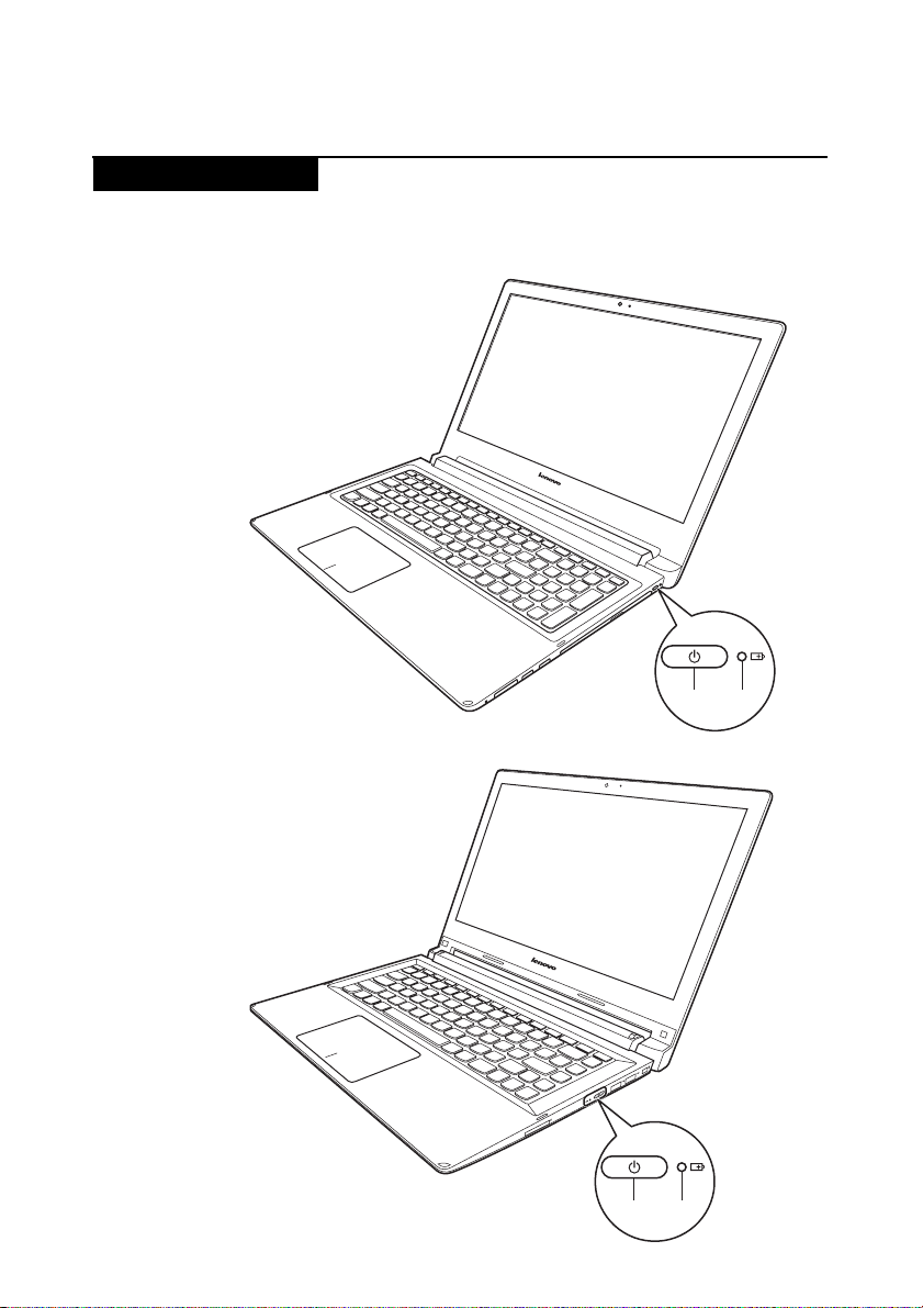
Status indicators
The system status indicators below show the computer status:
Flex 2-15/Flex 2-15D:
Lenovo Flex 2-14/Flex 2-14D/Flex 2-15/Flex 2-15D
a b
Flex 2-14/Flex 2-14D:
a b
29
Page 34

Lenovo Flex 2-14/Flex 2-14D/Flex 2-15/Flex 2-15D Hardware Maintenance Manual
Table 2. Status indicators
Indicator Indicator
Power status
indicator
Battery
status
indicator
status
On (solid
white)
Blinking — The computer is in sleep mode.
Off — The computer is powered off.
On (solid
white)
Solid
amber
Fast
blinking
amber
Slow
blinking
amber
Slow
blinking
white
Charge
Status
—The computer is powered on.
Discharging The battery has more than 20%
Discharging The battery has between 5% and 20%
Charging/
Discharging
Charging The battery is being charged. When
Charging The battery has between 20% and
Meaning
charge.
charge.
The battery has less than 5% charge.
battery charge reaches 20%, the
blinking color changes to white.
80% charge and is still charging.
When the battery reaches 80% charge
the light will stop blinking, but
charging will continue until the
battery is fully charged.
30
Page 35
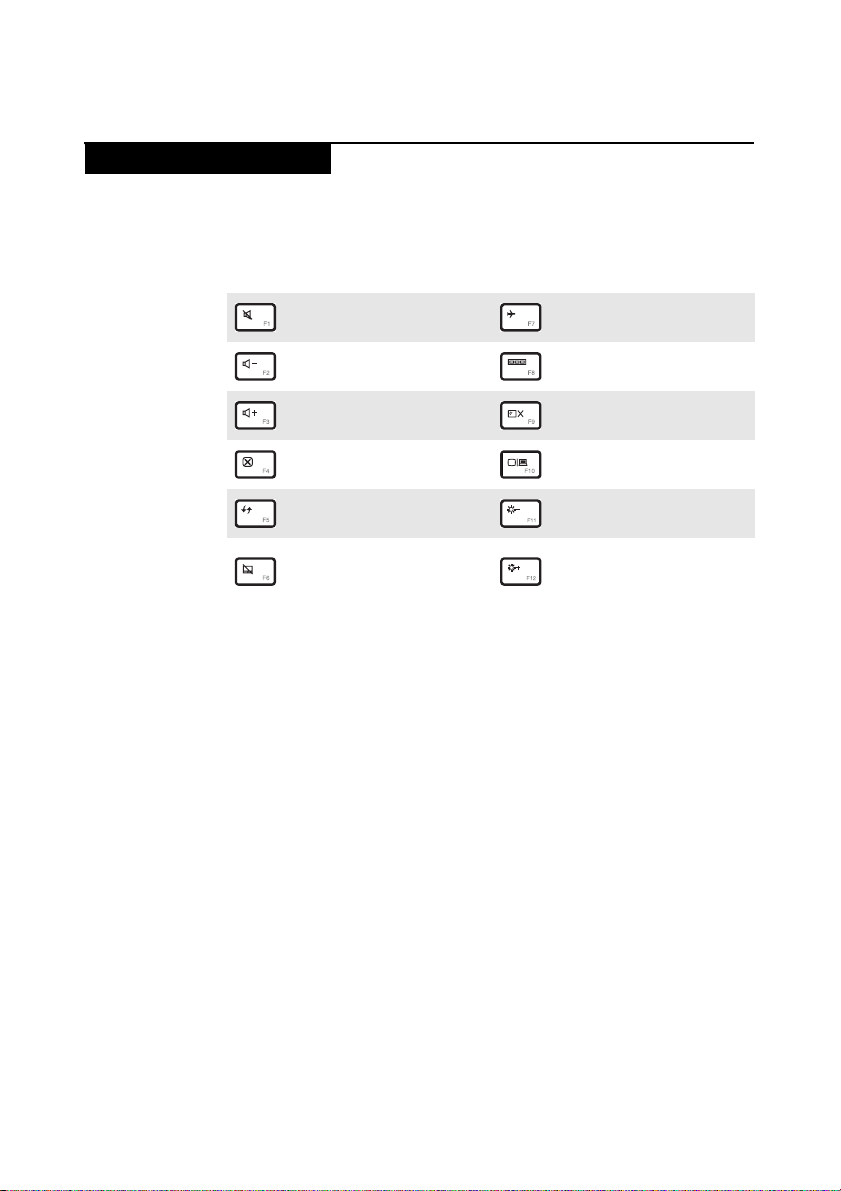
Hotkeys
Lenovo Flex 2-14/Flex 2-14D/Flex 2-15/Flex 2-15D
The hotkeys are located in the function key row of the keyboard.By pressing the
appropriate hotkey, you can change system settings instantly.
The following describes the function of each hotkey.
Table 3. Hotkeys
Mutes/unmutes the sound.
:
Decreases the volume level.
:
Increases the volume level.
:
Closes the currently active
:
window.
Refreshes the desk top or the
:
currently active window.
Enables/disables the
touch pad and the touch
:
pad buttons.
Enables/disables airplane
:
mode.
Switches the active
:
program.
Turns on/off the backlight
:
of the display.
Projects to a connected
:
display.
Decreases display
:
brightness.
Increases display
:
brightness.
31
Page 36
Lenovo Flex 2-14/Flex 2-14D/Flex 2-15/Flex 2-15D Hardware Maintenance Manual
FRU replacement notices
This section presents notices related to removing and replacing parts. Read this
section carefully before replacing any FRU.
Screw notices
Loose screws can cause a reliability problem. In the Lenovo computer, this
problem is addressed with special nylon-coated screws that have the following
characteristics:
• They maintain tight connections.
• They do not easily come loose, even with shock or vibration.
• They are harder to tighten.
• Each one should be used only once.
Do the following when you service this machine:
• Keep the screw kit in your tool bag.
• Remove screws carefully for reuse.
• Use a torque screwdriver if you have one.
Tighten screws as follows:
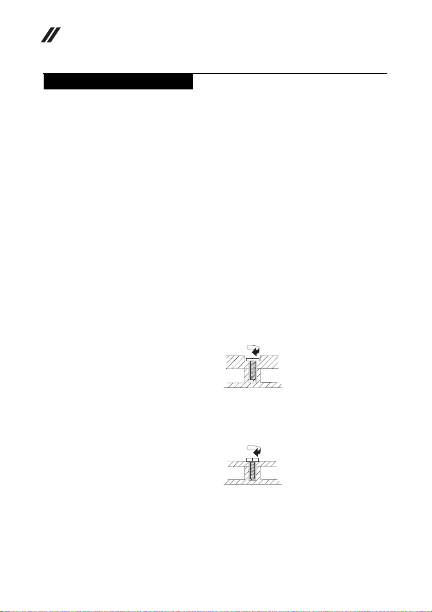
• Plastic to plastic
Turn an additional 90° after the screw head touches the surface of the plastic
part:
more than 90°
32
(Cross-section)
• Logic card to plastic
Turn an additional 180° after the screw head touches the surface of the logic
card:
more than 180°
(Cross-section)
• Torque driver
If you have a torque screwdriver , refer to the “Torque” column for each step.
• Make sure that you use the correct screws. If you have a torque screwdriver,
tighten all screws firmly to the torque shown in the table. Never use a screw
that you removed. Use a new one. Make sure that all screws are
tightened firmly.
• Ensure torque screwdrivers are calibrated correctly following country
specifications.
Page 37
Lenovo Flex 2-14/Flex 2-14D/Flex 2-15/Flex 2-15D
Removing and replacing an FRU
This section presents exploded figures with the instructions to indicate how to
remove and replace the FRU. Make sure to observe the following general rules:
1. Do not attempt to service any computer unless you have been trained and
certified. An untrained person runs the risk of damaging parts.
2. Before replacing any FRU, review “FRU replacement notices” on page 32.
3. Begin by removing any FRUs that have to be removed before the failing FRU.
Any of such FRUs are listed at the top of the page. Remove them in the order
in which they are listed.
4. Follow the correct sequence in the steps to remove the FRU, as given in the
figures by the numbers in square callouts.
5. When turning a screw to replace an FRU, turn it in the direction as given by
the arrow in the figure.
6. When removing the FRU, move it in the direction as given by the arrow in the
figure.
7. To put the new FRU in place, reverse the removal procedures and follow any
of the notes that pertain to replacement. For information about connecting
and arranging internal cables, see “Locations” on page 70.
8. When replacing an FRU, use the correct screw as shown in the procedures.
DANGER
Before removing any FRU, turn off the computer, unplug all power cords
from electrical outlets, remove the battery pack, and then disconnect any of
the interconnecting cables.
Attention: After replacing an FRU, do not turn on the computer until you have
made sure that all screws, springs, and other small parts are in place and none
are loose inside the computer. Verify this by shaking the computer gently and
listening for rattling sounds. Metallic parts or metal flakes can cause electrical
short circuits.
Attention: The system board is sensitiv e to, and can be damaged by, elec trostatic
discharge. Before touching it, establish personal grounding by touching a
ground point with one hand or using an electrostatic discharge (ESD) strap
(P/N 6405959) to remove potential shock reasons.
Note: The illustrations used in this section are of the Lenovo Ideapad Flex 2-15/
Flex 2-15D, unless otherwise stated.
33
Page 38
Lenovo Flex 2-14/Flex 2-14D/Flex 2-15/Flex 2-15D Hardware Maintenance Manual
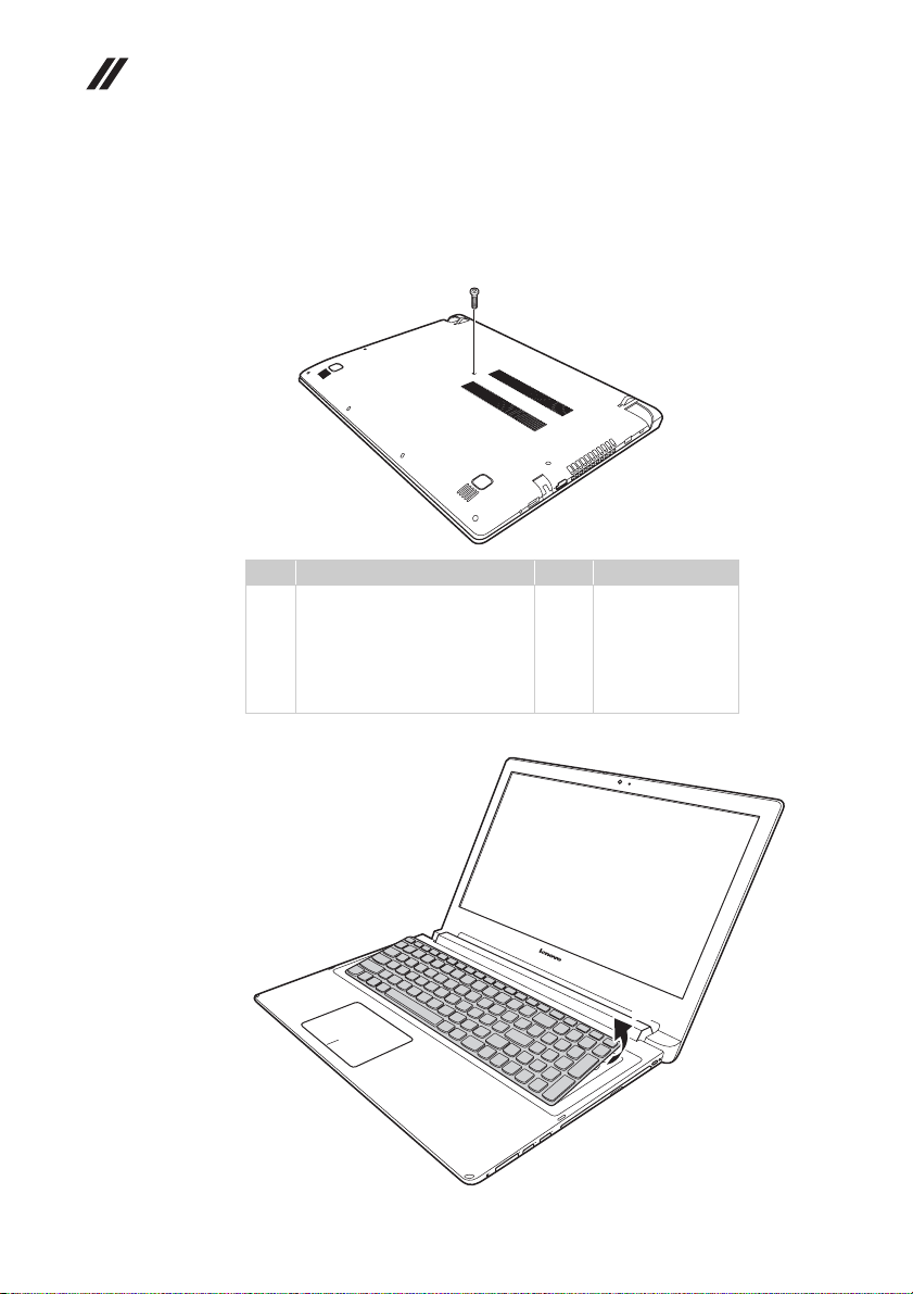
1010 Keyboard
Figure 1. Removal steps of keyboard
Remove screw .
Step Screw (quantity) Color Torque
a
Loosen the keyboard with fingers in the direction shown by arrow .
a
a
M2.0 × 6 mm, flat-head, nylokcoated (1) (Flex 2-14/
Flex 2-14D)
M2.0 × 6 mm, flat-head, nylokcoated(1) (Flex 2-15/
Flex 2-15D)
Black
Black
18~2.0 kgfcm
1.85+/-0.15 kgfcm
b
34
b
Page 39
Lenovo Flex 2-14/Flex 2-14D/Flex 2-15/Flex 2-15D
d
e
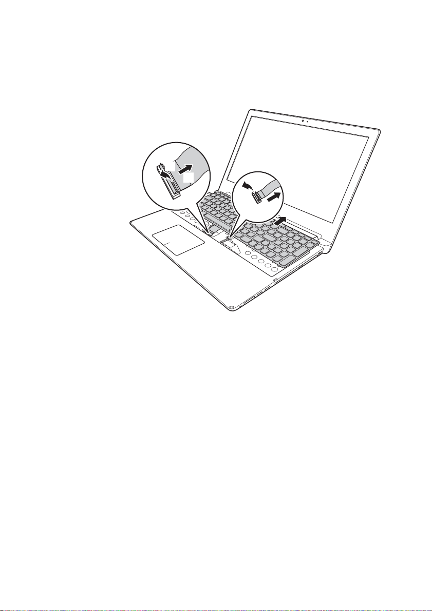
Figure 1. Removal steps of keyboard (continued)
Lift the keyboard a little , and then detach the connector in the direction
shown by arrows and .
d
When installing: Make sure that the FPC connectors are attached firmly.
c
e f g
f
g
c
35
Page 40
Lenovo Flex 2-14/Flex 2-14D/Flex 2-15/Flex 2-15D Hardware Maintenance Manual
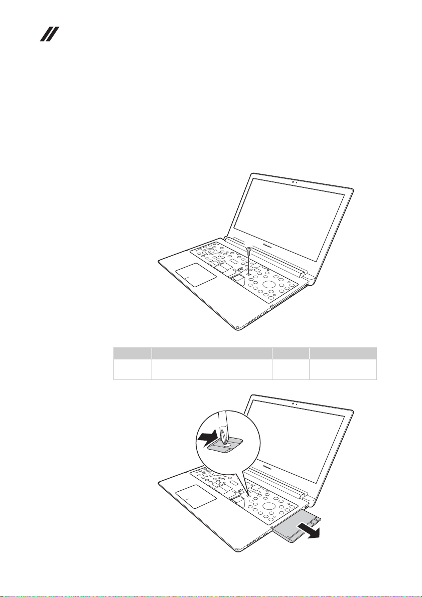
1020 Optical drive
For access, remove this FRU:
• “1010 Keyboard” on page 34
Figure 2. Removal steps of optical drive
Remove the screw , insert a screwdriver into the screw hole and push the
optical drive in the d irection shown by arrow . Pull the optical drive out in the
direction shown by arrow .
a
b
c
a
36
Step Screw (quantity) Color Torque
a
M2 × 6 mm, flat-head, nylokcoated
(1) (Flex 2-15/Flex 2-15D)
b
Black 1.85+/-0.15 kgfcm
c
Page 41
Lenovo Flex 2-14/Flex 2-14D/Flex 2-15/Flex 2-15D
c
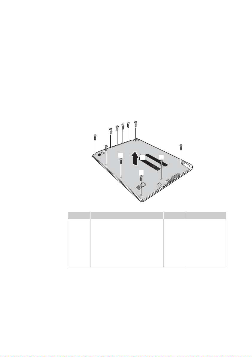
1030 Hard disk drive(HDD)/Memory/Mini PCI Express Card slot compartment cover
For access, remove these FRUs in order:
• “1010 Keyboard” on page 34
• “1020 Optical drive” on page 36
Figure 3. Removal steps of HDD/Memory/Mini PCI Express Card slot compartment
cover
Loosen the screws and that secure the compartment cover. Remove
the compartment cover .
a b
d
b
a
a
a
b
c
c
b
c
Step Screw (quantity) Color Torque
a
M2 × 6 mm, flat-head, nylokcoated (8) (Flex 2-14/Flex 2-14D)
M2 × 3.5 mm, flat-head, nylokcoated (4) (Flex 2-15/Flex 2-15D)
M2 × 6 mm, flat-head, nylokcoated (4) (Flex 2-15/Flex 2-15D)
M2 × 2 mm, flat-head, nylokcoated (3) (Flex 2-15/Flex 2-15D)
d
c
b
Black
Black
Black
Black
18~2.0 kgfcm
1.85+/-0.15 kgfcm
1.85+/-0.15 kgfcm
1.85+/-0.15 kgfcm
37
Page 42
Lenovo Flex 2-14/Flex 2-14D/Flex 2-15/Flex 2-15D Hardware Maintenance Manual
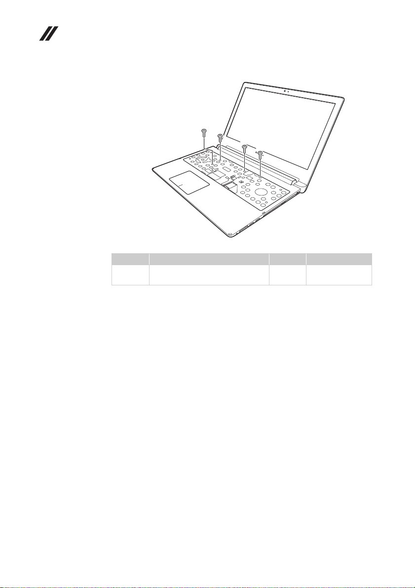
Remove screws .
Step Screw (quantity) Color Torque
a
e
e
e
e
M2 × 3.5 mm, flat-head, nylokcoated (4)
e
Black 1.85+/-0.15 kgfcm
38
Page 43
Lenovo Flex 2-14/Flex 2-14D/Flex 2-15/Flex 2-15D
b
1040 Battery pack
For access, remove these FRUs in order:
• “1010 Keyboard” on page 34
• “1020 Optical drive” on page 36
• “1030 Hard disk drive(HDD)/Memory/Mini PCI Express Card slot
compartment cover” on page 37
DANGER
Only use the battery specified in the parts list for your computer. Any other
battery could ignite or explode.
Figure 4. Removal steps of battery pack
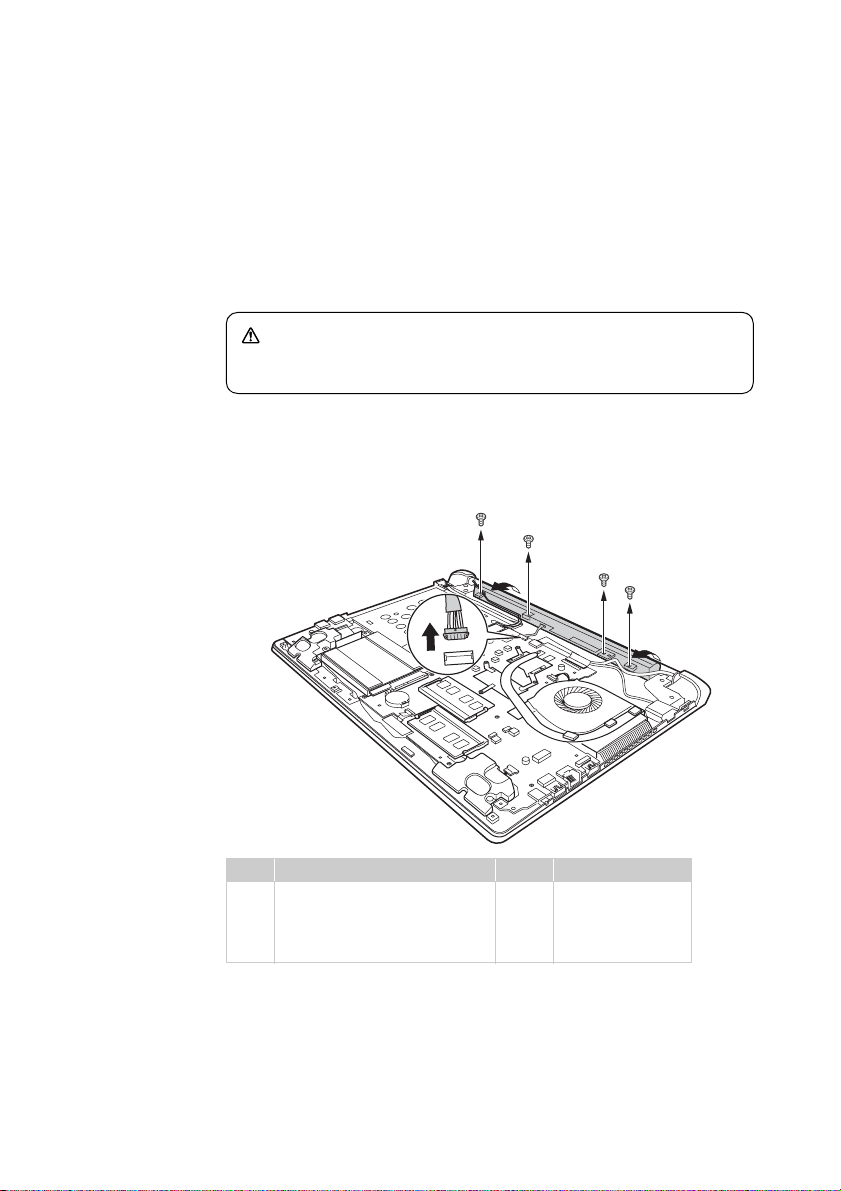
Remove screws . Unplug connector in the direction shown by arrow .
Remove the battery pack in the direction shown by the arrow .
a
a
a
c
b
c
Step Screw (quantity) Color Torque
M2 × 4 mm, flat-head, nylok-
a
coated (4) (Flex 2-14/2-14D)
M2 x 3.5 mm, flat-head, nylok-
coated (4) (Flex 2-15/2-15D)
Silver
Black
a
a
c
1.8~2.0 kgfcm
1.85+/-0.15 kgfcm
39
Page 44
Lenovo Flex 2-14/Flex 2-14D/Flex 2-15/Flex 2-15D Hardware Maintenance Manual
1050 Hard disk drive
For access, remove these FRUs in order:
• “1010 Keyboard” on page 34
• “1020 Optical drive” on page 36
• “1030 Hard disk drive(HDD)/Memory/Mini PCI Express Card slot
compartment cover” on page 37
• “1040 Battery pack” on page 39
Attention:
• Do not drop the hard disk drive or apply any physical shock to it.
The hard disk drive is sensitive to physical shock. Improper handling
can cause damages and permanent loss of data.
• Before removing the drive, suggest the customer to backup all the
information on it if possible.
• Never remove the drive while the system is operating or is in suspend
mode.
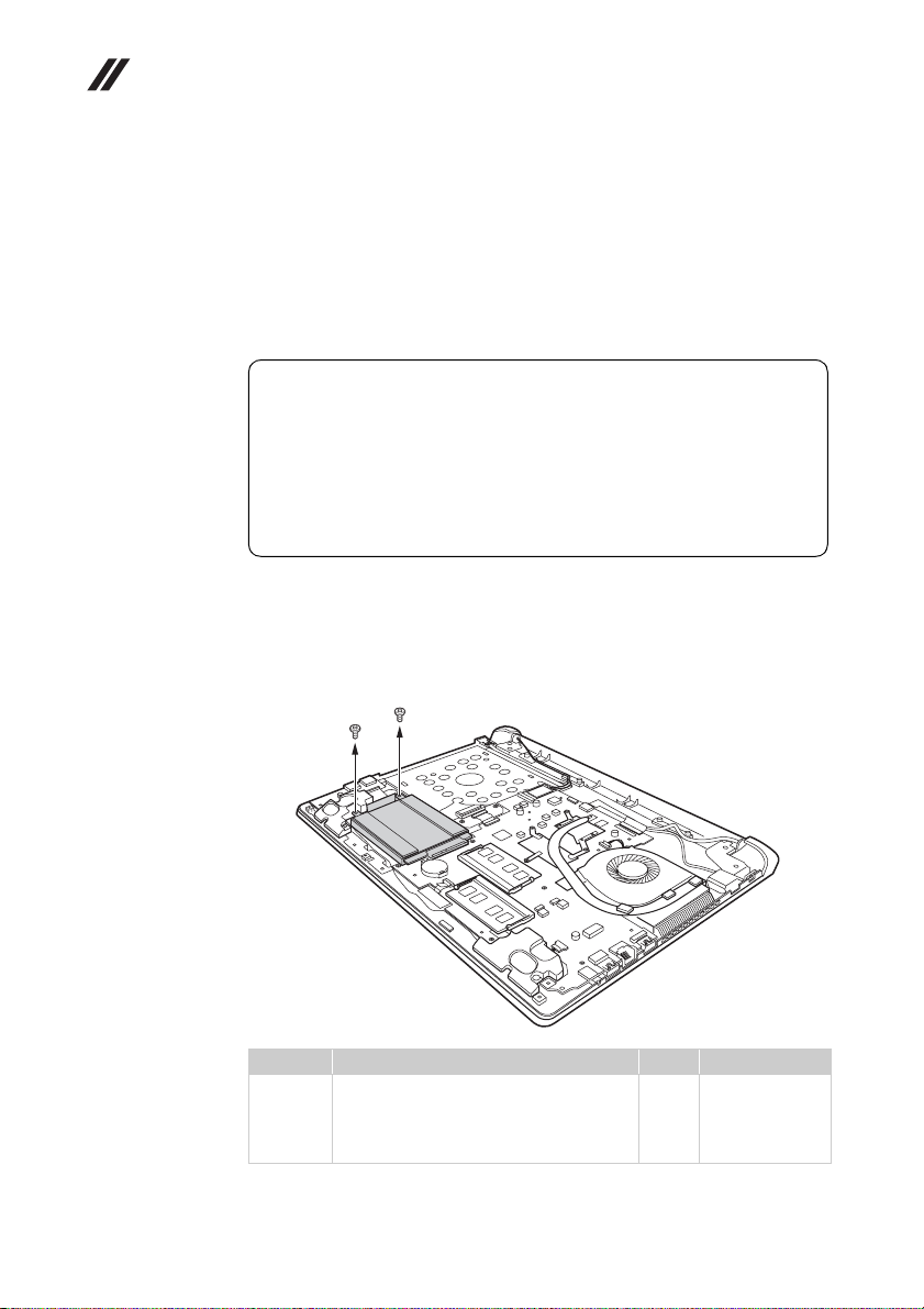
Figure 5. Removal steps of hard disk drive
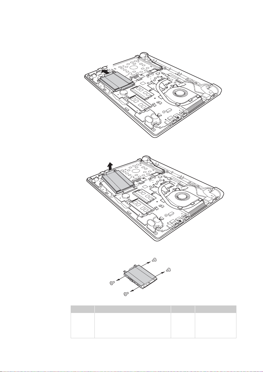
Figure 5. Removal steps of hard disk drive (continued)
Remove the frame fixing screws .
a
a
a
40
Step Screw (quantity) Color Torque
a
M2 × 4 mm, flat-head, nylok-coated (2)
(Flex 2-14/2-14D)
M2 × 3.5 mm, flat-head, nylok-coated (2)
(Flex 2-15/2-15D)
Silver
Black
1.8~2.0 kgfcm
1.85+/-0.15 kgfcm
Page 45
Lenovo Flex 2-14/Flex 2-14D/Flex 2-15/Flex 2-15D
c
d
d
c
Pull the tab in the direction shown by arrow .
b
Take out the hard disk drive secured in a metal frame in the direction shown by
arrow .
c
b
Remove four screws and detach the metal frame from the hard disk drive.
d
d
d
Step Screw (quantity) Color Torque
M3.0 × 4 mm, flat-head, nylokcoated (4) (Flex 2-14/2-14D)
M3.0 × 3.0 mm, flat-head, nylokcoated (4) (Flex 2-15/2-15D)
When installing: Make sure that the HDD connector is attached firmly.
Silver
Black
1.8~2.0 kgfcm
3.0+/-0.3 kgfcm
41
Page 46
Lenovo Flex 2-14/Flex 2-14D/Flex 2-15/Flex 2-15D Hardware Maintenance Manual
1060 DIMM
For access, remove these FRUs in order
• “1010 Keyboard” on page 34
• “1020 Optical drive” on page 36
• “1030 Hard disk drive(HDD)/Memory/Mini PCI Express Card slot
compartment cover” on page 37
• “1040 Battery pack” on page 39
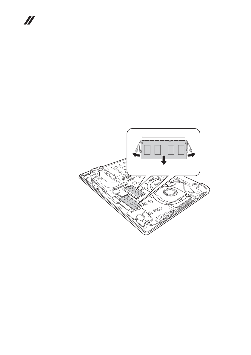
Figure 6. Removal steps of DIMM
Release the two latches on both edges of the socket at the same time in the
direction shown by arrows , and then unplug the DIMM in the direction
shown by arrow .
b
a
aa
b
42
When installing: Insert the notched end of the DIMM into the socket. Push the
DIMM firmly, and pivot it until it snaps into the place. Make sure that it is firmly
fixed in the slot and difficult to be moved.
Page 47
Lenovo Flex 2-14/Flex 2-14D/Flex 2-15/Flex 2-15D
1070 PCI Express Mini Card for wireless LAN/WAN
For access, remove these FRUs in order
• “1010 Keyboard” on page 34
• “1020 Optical drive” on page 36
• “1030 Hard disk drive(HDD)/Memory/Mini PCI Express Card slot
compartment cover” on page 37
• “1040 Battery pack” on page 39
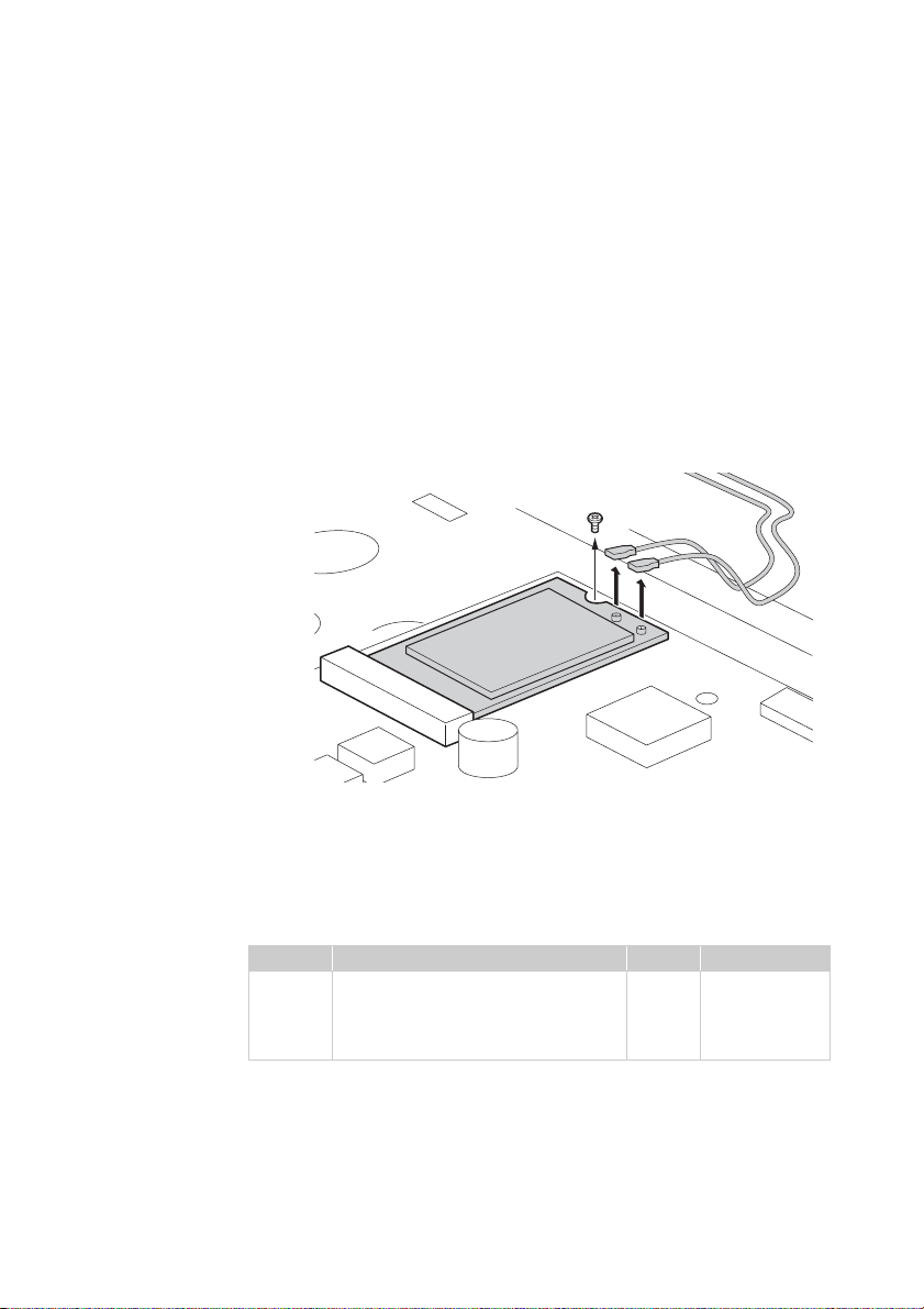
Figure 7. Removal steps of PCI Express Mini Card for wireless LAN/WAN
Disconnect the two wireless LAN cables (black, white) , and then remove the
screw .
b
b
a
a
In step , unplug the jacks by using the removal tool antenna RF connector
a
(P/N: 08K7159), or pick up the connectors with your fingers and gently unplug
them in the direction shown by arrows.
Notes: wireless LAN card has 2 cables in step .
wireless LAN card in some models may have 3 cables in step .
Step Screw (quantity) Color Torque
b
M2 × 3.0 mm, flat-head, nylok-coated
(1) (Flex 2-14/2-14D)
M2 × 3.5 mm, flat-head, nylok-coated
(1) (Flex 2-15/2-15D)
a
Black
Black
a
1.5~1.8 kgfcm
1.85+/-0.15
kgfcm
43
Page 48
Lenovo Flex 2-14/Flex 2-14D/Flex 2-15/Flex 2-15D Hardware Maintenance Manual
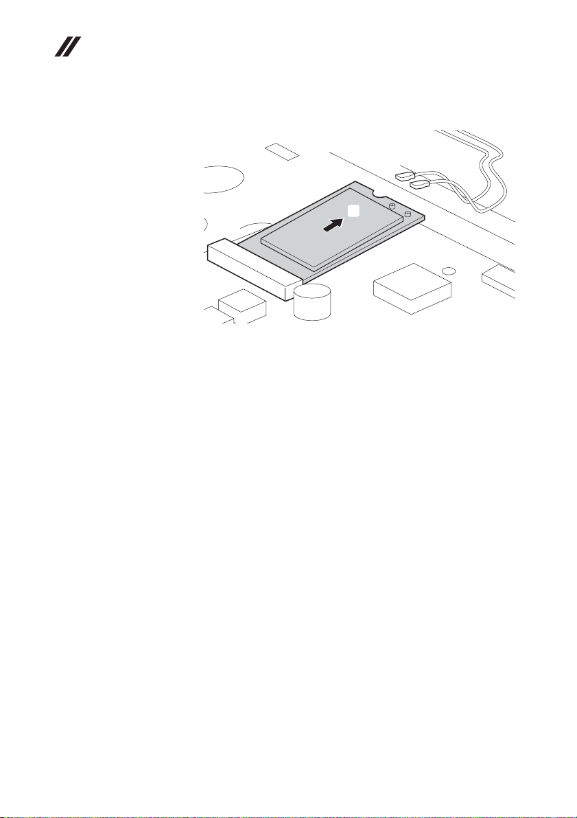
Figure 7. Removal steps of PCI Express Mini Card for wireless LAN/WAN (continued)
Remove the card in the direction shown by arrow .
When installing:
• In models with a wireless LAN card that has two antenna connectors, plug
the black cable (1st) (MAIN) into the jack labeled 1, and the white cable (2nd)
(AUX) into jack labeled 2 on the card.
• In models with a wireless LAN card that has three antenna connectors, plug
the black cable (1st) (MAIN) into the jack labeled 1, the grey cable (3rd) into
jack labeled 3, and the white cable (2nd) (AUX) into jack labeled 2 on the
card.
c
c
44
Page 49
Lenovo Flex 2-14/Flex 2-14D/Flex 2-15/Flex 2-15D
1080 Fan assembly and Heat Sink assembly
For access, remove these FRUs in order:
• “1010 Keyboard” on page 34
• “1020 Optical drive” on page 36
• “1030 Hard disk drive(HDD)/Memory/Mini PCI Express Card slot
compartment cover” on page 37
• “1040 Battery pack” on page 39
• “1050 Hard disk drive” on page 40
• “1060 DIMM” on page 42
• “1070 PCI Express Mini Card for wireless LAN/WAN” on page 43
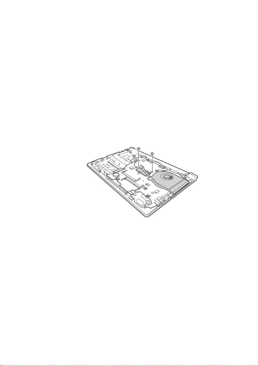
Figure 8. Removal steps of fan assembly and heat sink assembly
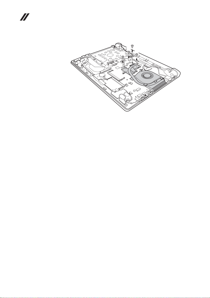
Loosen screws .
Flex 2-14/Flex 2-14D:
a
a
a
a
45
Page 50
Lenovo Flex 2-14/Flex 2-14D/Flex 2-15/Flex 2-15D Hardware Maintenance Manual
Flex 2-15/Flex 2-15D:
a
a
a
a
46
Page 51
Lenovo Flex 2-14/Flex 2-14D/Flex 2-15/Flex 2-15D
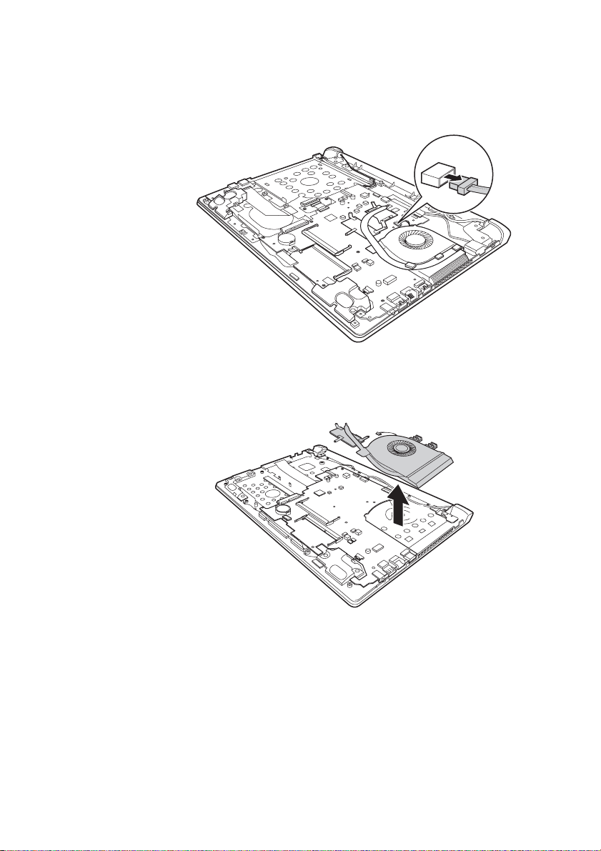
b
Figure 8. Removal steps of fan assembly and heat sink assembly (continued)
Unplug the fan connector in the direction shown by arrow .
When installing: Make sure that the fan connector is attached firmly to the
system board.
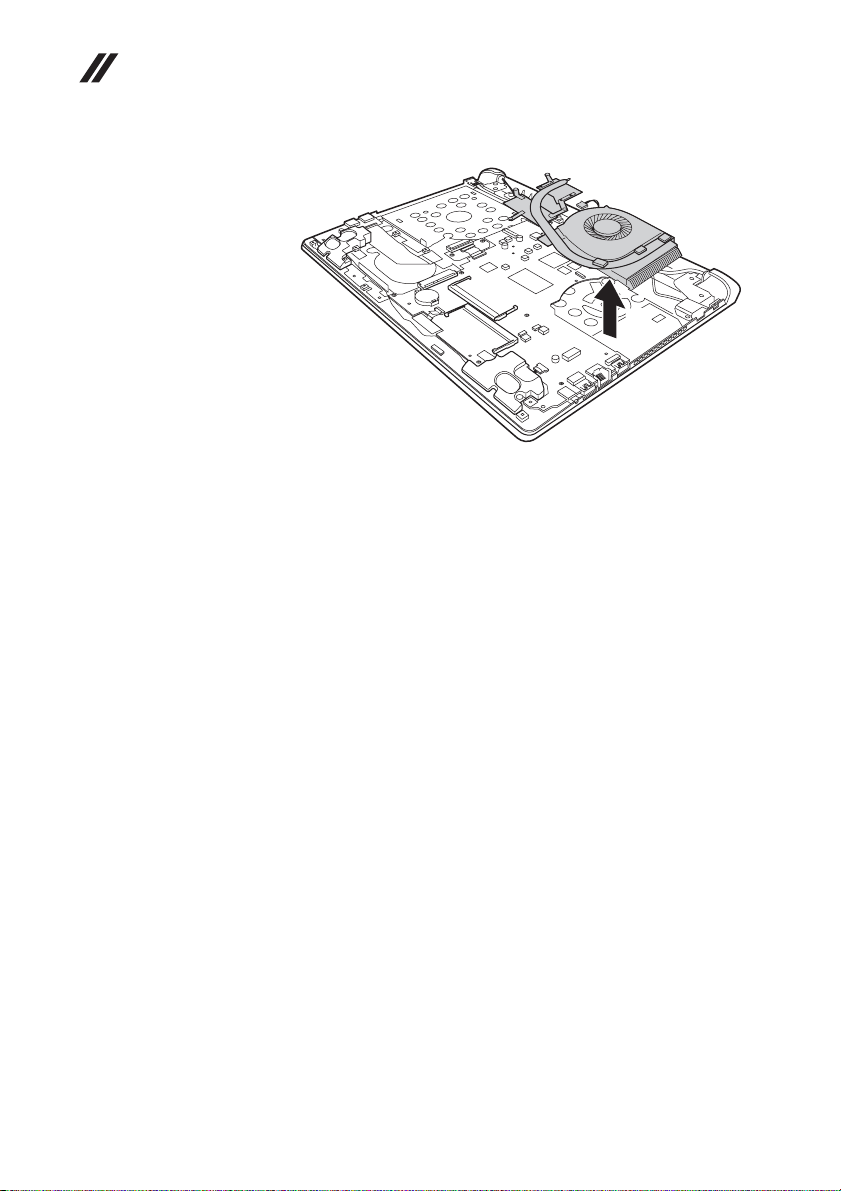
Lift the fan assembly in the direction shown by arrow . Be careful not to
damage the connector.
Flex 2-14/Flex 2-14D:
b
c
c
47
Page 52
Lenovo Flex 2-14/Flex 2-14D/Flex 2-15/Flex 2-15D Hardware Maintenance Manual
Flex 2-15/Flex 2-15D:
c
48
Page 53

Lenovo Flex 2-14/Flex 2-14D/Flex 2-15/Flex 2-15D
1090 System board
Important notices for handling the system board:
When handling the system board, bear the following in mind.
• Be careful not to drop the system board on a bench top that has a hard
surface, such as metal, wood, or composite.
• Avoid rough handling of any kind.
• In the whole process, make sure not to drop or stack the system board.
• If you put a system board down, make sure to put it only on a padded
surface such as an ESD mat or conductive corrugated material.
For access, remove these FRUs in order:
• “1010 Keyboard” on page 34
• “1020 Optical drive” on page 36
• “1030 Hard disk drive(HDD)/Memory/Mini PCI Express Card slot
compartment cover” on page 37
• “1040 Battery pack” on page 39
• “1050 Hard disk drive” on page 40
• “1060 DIMM” on page 42
• “1070 PCI Express Mini Card for wireless LAN/WAN” on page 43
• “1080 Fan assembly and Heat Sink assembly” on page 45
49
Page 54
Lenovo Flex 2-14/Flex 2-14D/Flex 2-15/Flex 2-15D Hardware Maintenance Manual
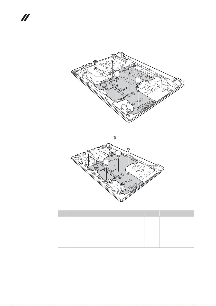
Figure 9. Removal steps of system board (continued)
Flex 2-15/Flex 2-15D: Remove five screws .
a
a
a
a
a
a
Flex 2-14/Flex 2-14 D: Remove two screws and five screws .
a
b
b
b
Step Screw (quantity) Color Torque
M2 × 3 mm, flat-head, nylok-coated (2)
a
(Flex 2-14/Flex 2-14D)
M2 × 4 mm, flat-head, nylok-coated (5)
(Flex 2-14/Flex 2-14D)
M2.0 × 3.5 mm, flat-head, nylok-coated (5)
(Flex 2-15/Flex 2-15D)
a b
a
b
b
Black
Silver
Black
1.5~1.8 kgfcm
1.8~2.0 kgfcm
1.85+/-0.15 kgfcm
50
Page 55
Lenovo Flex 2-14/Flex 2-14D/Flex 2-15/Flex 2-15D
c
Figure 9. Removal steps of system board (continued)
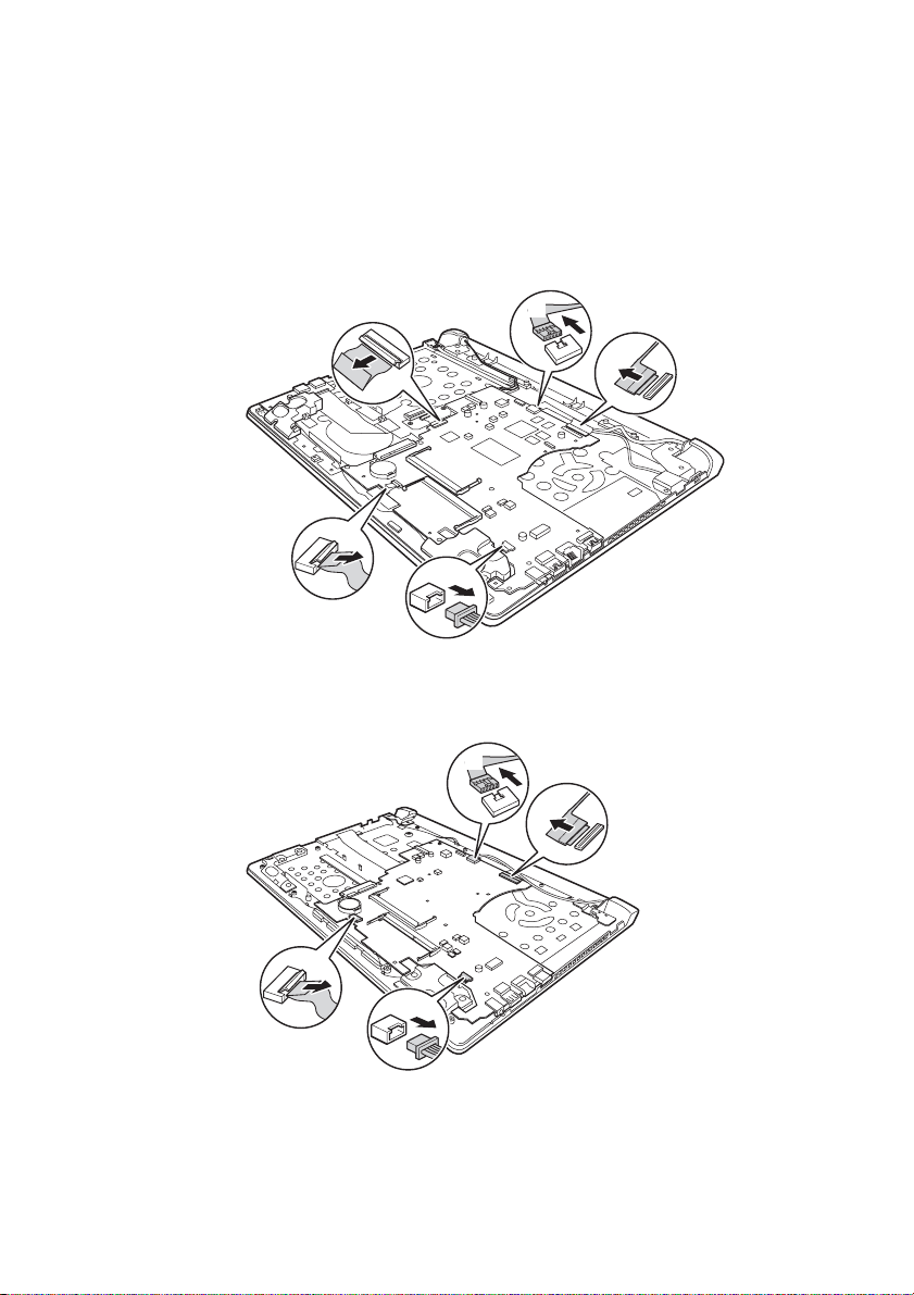
Flex 2-15/Flex 2-15D: Unplug DC-IN cable connector in the direction shown by
arrow , speakers connector in the direction shown by arrow , detach ODD
f
transfer board connector in the direction shown by arrow , touch pad
connector in the direction shown by arrow , disconnect LCD connector in the
direction shown by arrow .
d
Flex 2-14/Flex 2-14 D: Unplug DC-IN cable connector in the direction shown by
arrow , speakers connector in the direction shown by arrow , detach touch
f c
pad connector in the direction shown by arrow , disconnect LCD connector
in the direction shown by arrow .
g
e
c
e
d
f
d
e
g
f
g
d
e
When installing: Make sure that all the connectors are attached firmly.
51
Page 56
Lenovo Flex 2-14/Flex 2-14D/Flex 2-15/Flex 2-15D Hardware Main-
h
tenance Manual
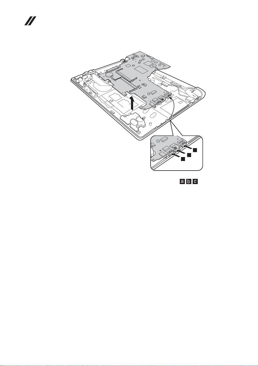
Remove the system board in the direction shown by arrow .
h
c
b
a
When installing: When attaching the system board to the base cover, adjust the
placement of the USB, RJ-45, HDMI ports as shown in , and make sure
that they are attached to the holes on the base cover as shown. Improper
placement of those jacks might cause a damage.
52
Page 57
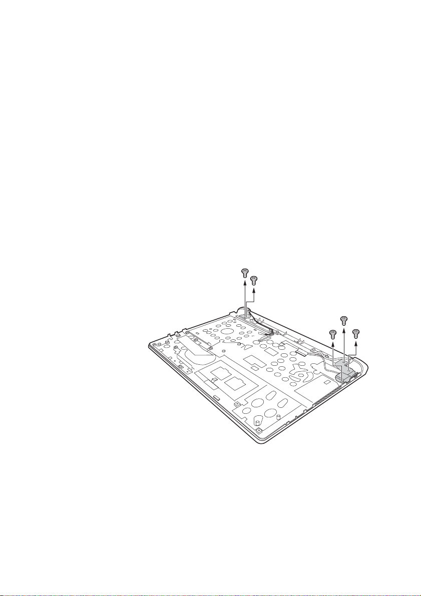
Lenovo Flex 2-14/Flex 2-14D/Flex 2-15/Flex 2-15D
1100 LCD unit
For access, remove these FRUs in order
• “1010 Keyboard” on page 34
• “1020 Optical drive” on page 36
• “1030 Hard disk drive(HDD)/Memory/Mini PCI Express Card slot
compartment cover” on page 37
• “1040 Battery pack” on page 39
• “1050 Hard disk drive” on page 40
• “1060 DIMM” on page 42
• “1070 PCI Express Mini Card for wireless LAN/WAN” on page 43
• “1080 Fan assembly and Heat Sink assembly” on page 45
• “1090 System board” on page 49
Figure 10. Removal steps of LCD unit
Remove five screws .
Flex 2-15/Flex 2-15D:
a
a
a
a
a
a
53
Page 58
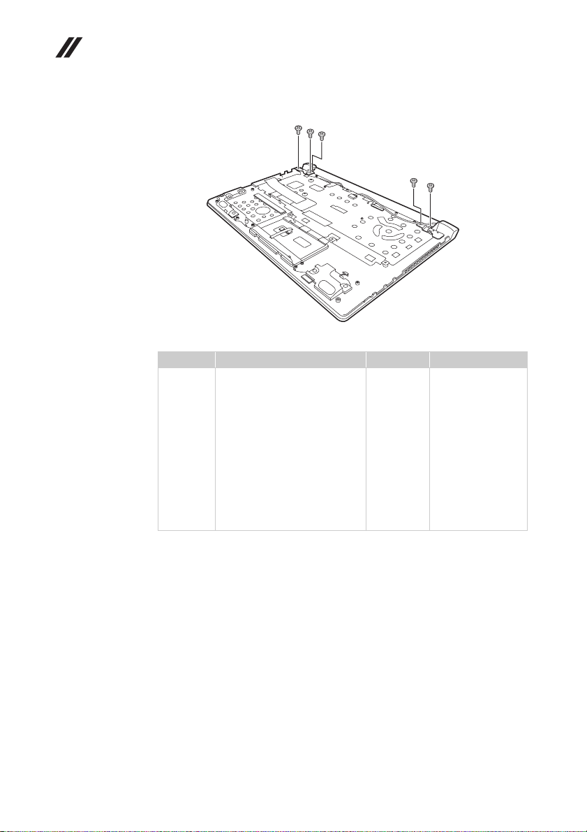
Lenovo Flex 2-14/Flex 2-14D/Flex 2-15/Flex 2-15D Hardware Maintenance Manual
Flex 2-14/Flex 2-14 D:
a
a
a
a
a
Step Screw (quantity) Color Torque
a
M2.5 × 4 mm, flat-head, nylokcoated (5) (Flex 2-14/
Flex 2-14D)
M2.5 × 4.5 mm, flat-head,
nylok-coated (4) (Flex 2-15/
Flex 2-15D)
M2.5 × 4.5 mm, flat-head,
nylok-coated (Flex 2-15/
Flex 2-15D)
M2.0 × 3.5 mm, flat-head,
nylok-coated (Flex 2-15/
Flex 2-15D)
Silver
Silver
Silver
Black
18~2.0 kgfcm
3.0+/-0.3 kgfcm
3.0+/-0.3 kgfcm
1.85+/-0.15 kgfcm
54
When installing:
• Route the antenna cables along the cable guides. As you route the cables,
make sure that they are not subjected to any tension. Tension could cause the
cables to be damaged by the cable guides, or a wire to be broken.
• Make sure that the LCD connector is attached firmly and make sure that you
do not pinch the antenna cables when you attach the LCD assembly. Route
the LCD cable along the cable guides.
Page 59
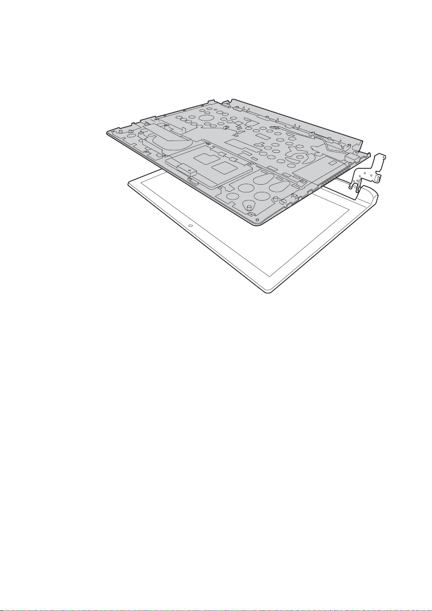
Lenovo Flex 2-14/Flex 2-14D/Flex 2-15/Flex 2-15D
Figure 10. Removal steps of LCD unit (continued)
Detach the LCD unit from the upper case.
55
Page 60
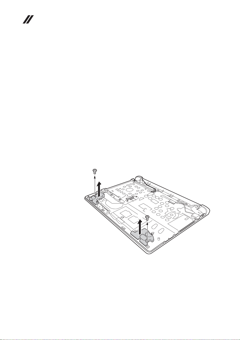
Lenovo Flex 2-14/Flex 2-14D/Flex 2-15/Flex 2-15D Hardware Maintenance Manual
1110 Speakers, base cover, IO board, DC-IN, power board and ODD transfer board
For access, remove these FRUs in order:
• “1010 Keyboard” on page 34
• “1020 Optical drive” on page 36
• “1030 Hard disk drive(HDD)/Memory/Mini PCI Express Card slot
compartment cover” on page 37
• “1040 Battery pack” on page 39
• “1050 Hard disk drive” on page 40
• “1060 DIMM” on page 42
• “1070 PCI Express Mini Card for wireless LAN/WAN” on page 43
• “1080 Fan assembly and Heat Sink assembly” on page 45
• “1090 System board” on page 49
• “1100 LCD unit” on page 53
Figure 11. Speakers, base cover, IO board, DC-IN, power board and ODD transfer board
Remove screws , and then remove the speakers in the direction shown by
arrows .
Flex 2-15/Flex 2-15 D:
a
b
a
b
56
a
b
Page 61
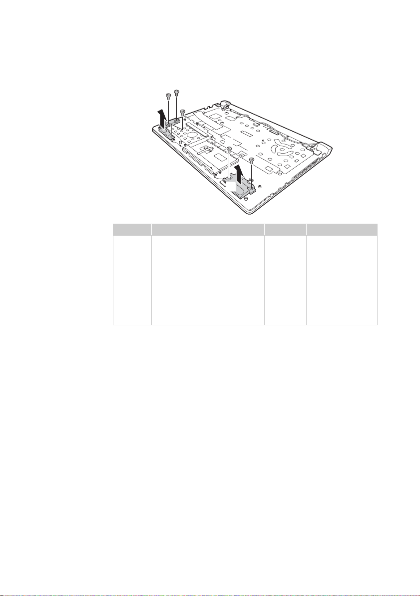
Lenovo Flex 2-14/Flex 2-14D/Flex 2-15/Flex 2-15D
Flex 2-14/Flex 2-14 D:
a
a
a
b
a
a
b
Step Screw (quantity) Color Torque
a
M2 × 3.1 mm, flat-head, nylokcoated (2) (Flex 2-15/
Flex 2-15D)
M2.0 × 6.8 mm, flat-head, nylokcoated (3) (Flex 14)
M2.0 × 5.5 mm, flat-head, nylokcoated (2) (Flex 15)
M2.0 × 6.8 mm, flat-head, nylokcoated (2) (Flex 15)
Black
Black
Black
Black
1.85+/-0.15 kgfcm
1.85+/-0.2 kgfcm
1.85+/-0.15 kgfcm
1.85+/-0.15 kgfcm
57
Page 62
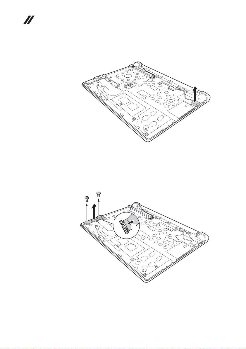
Lenovo Flex 2-14/Flex 2-14D/Flex 2-15/Flex 2-15D Hardware Main-
c
tenance Manual
Figure 11. Speakers, base cover, IO board, DC-IN, power board and ODD transfer board
(continued)
Remove the DC-IN in the direction shown by arrow .
When installing: Make sure that the power connector is attached firmly.
a
a
Flex 2-15/Flex 2-15 D: Remove screws , detach connector in the direction
shown by arrows and and then remove the IO board in the direction
shown by arrow .
b
d
a
a
d
b
a
c
58
Page 63
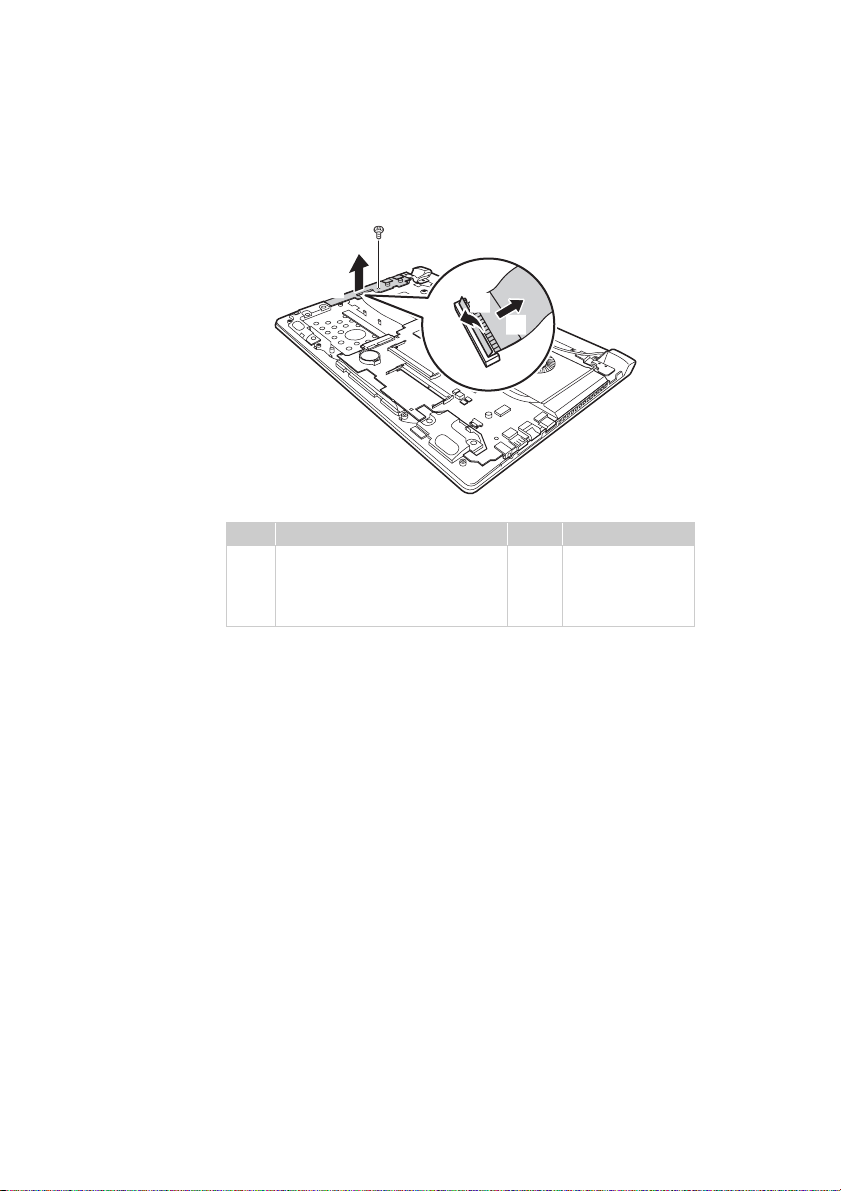
Lenovo Flex 2-14/Flex 2-14D/Flex 2-15/Flex 2-15D
c
c
Flex 2-14/Flex 2-14 D: Remove screw , detach connector in the direction
shown by arrows and and then remove the function board in the direction
shown by arrow .
b
d
a
d
a
b
Step Screw (quantity) Color Torque
M2 × 4 mm, flat-head, nylok-
a
coated (1) (Flex 2-14/Flex 2-14D)
M2.0 × 3.5 mm, flat-head, nylok-
coated (2) (Flex 2-15/Flex 2-15D)
Silver
Black
18~2.0 kgfcm
1.85+/-0.15 kgfcm
59
Page 64
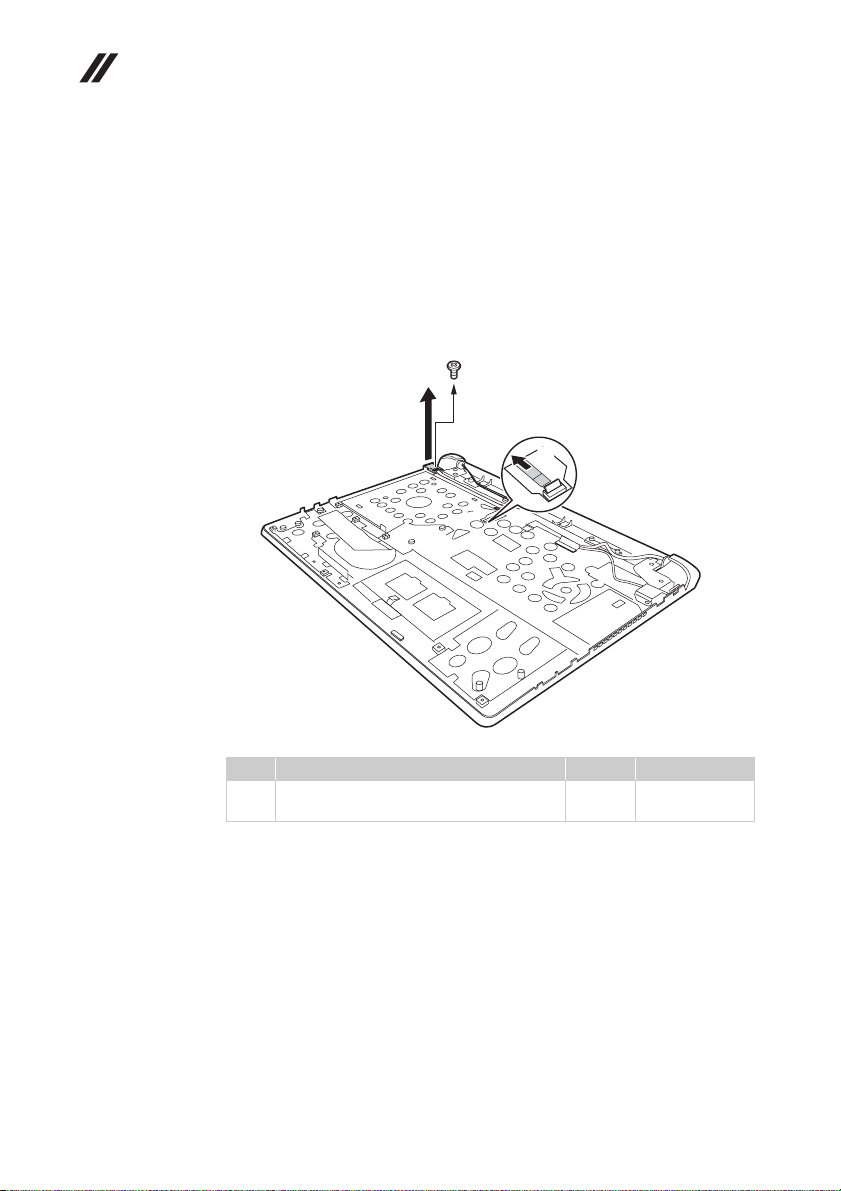
Lenovo Flex 2-14/Flex 2-14D/Flex 2-15/Flex 2-15D Hardware Maintenance Manual
Figure 11. Speakers, base cover, IO board, DC-IN, power board and ODD transfer board
(continued)
When installing: When attaching the audio board to the base cover, adjust the
placement of the USB and headphone jacks as shown , and make sure that both
of the USB and the headphone jacks are attached to the holes on the base cover.
Improper placement of the jacks might cause a damage.
Remove screw , detach the connector to lift the power board in the
direction shown by arrow .
Step Screw (quantity) Color Torque
a
a b
c
a
c
b
M2.0 × 3.5 mm, flat-head, nylok-coated (1)
(Flex 2-15/Flex 2-15D)
Black 1.85+/-0.15
kgfcm
60
Page 65
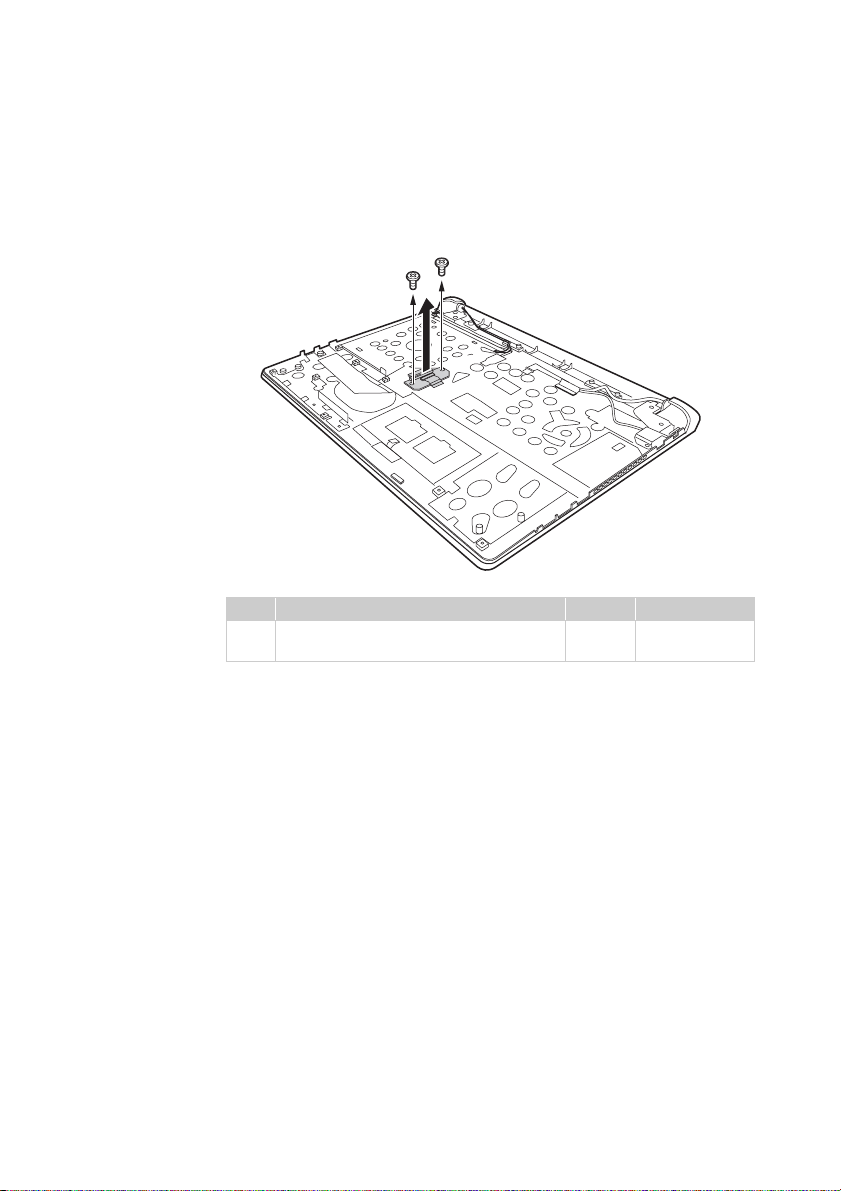
Lenovo Flex 2-14/Flex 2-14D/Flex 2-15/Flex 2-15D
Figure 11. Speakers, base cover, IO board, DC-IN, power board and ODD transfer board
(continued)
Remove screws to lift the ODD transfer board in the direction shown by
arrow .
b
Step Screw (quantity) Color Torque
a
a
a
a
b
M2.0 × 3.5 mm, flat-head, nylok-coated (2)
(Flex 2-15/Flex 2-15D)
Black 1.85+/-0.15
kgfcm
61
Page 66
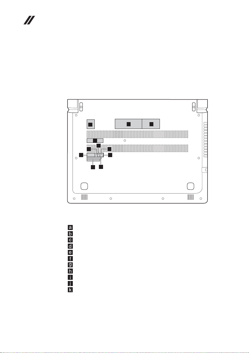
Lenovo Flex 2-14/Flex 2-14D/Flex 2-15/Flex 2-15D Hardware Maintenance Manual
Applying labels to the base cover
The new base cover FRU is shipped with a kit containing labels of several kinds.
Apply those labels when you replace the base cover. For labels which are not
shipped with the new base cover, peel them from the replaced base cover and
adhere them to the new one.
Note: If the Certificate of Authenticity (COA) label (b) is attached to a replaced
part, return the replaced part to the customer, or provide a letter to the customer
stating the original label part number, serial number, and product key.
Flex 2-14/Flex 2-14 D:
a
d
h
g
f
The following letter shows the correct location of each label. Not all labels are
attached on the part you are servicing.
GML label
Rating label-1
Rating label-2
Barcode label
WLAN Label for US/CA/TW
WLAN Label for South Africa
D Side label for Indonesia
BT Label for US/CA/TW or WLAN/BT Label for Isarel
KCC Label for Korea or BIS Label for India
Postel Label for Indonesia
WL/BT Label for Brazil
i
j
k
e
b
c
62
Page 67
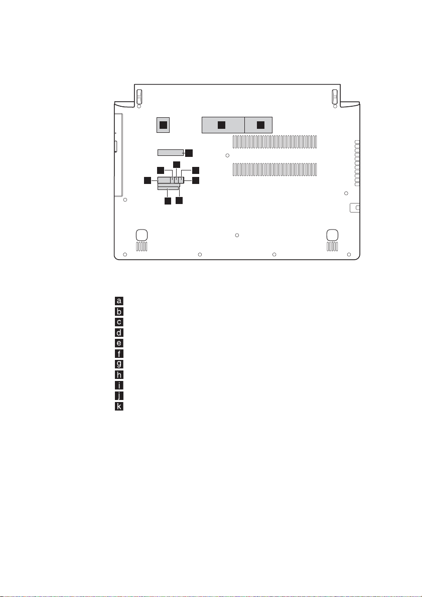
Lenovo Flex 2-14/Flex 2-14D/Flex 2-15/Flex 2-15D
Flex 2-15/Flex 2-15 D:
a
b
c
d
h
g
f
The following letter shows the correct location of each label. Not all labels are
attached on the part you are servicing.
GML label
Rating label-1
Rating label-2
Barcode label
WLAN Label for US/CA/TW
WLAN Label for South Africa
D Side label for Indonesia
BT Label for US/CA/TW or WLAN/BT Label for Isarel
KCC Label for Korea or BIS Label for India
Postel Label for Indonesia
WL/BT Label for Brazil
i
j
k
e
63
Page 68
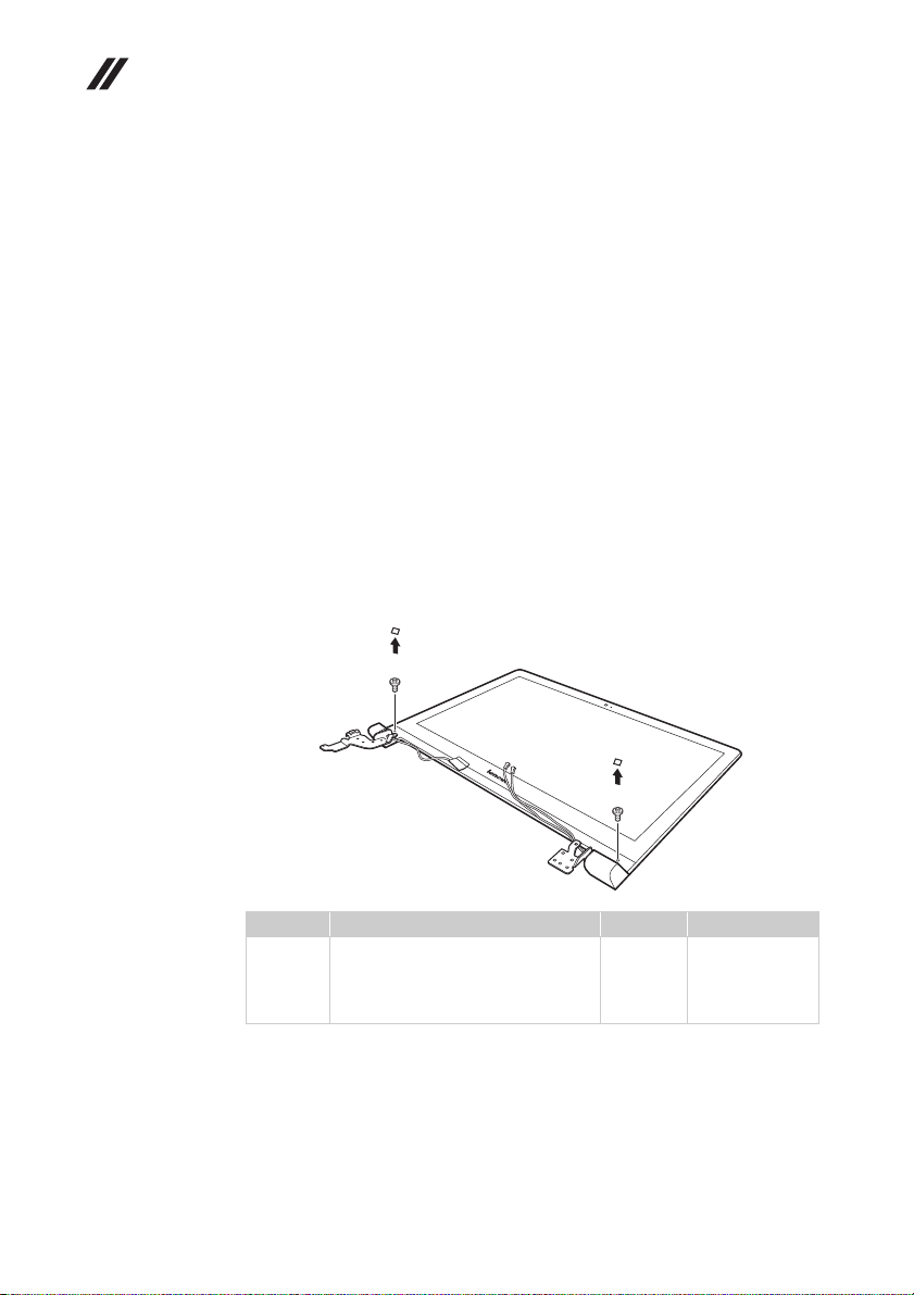
Lenovo Flex 2-14/Flex 2-14D/Flex 2-15/Flex 2-15D Hardware Maintenance Manual
1120 LCD front bezel
For access, remove these FRUs in order:
• “1010 Keyboard” on page 34
• “1020 Optical drive” on page 36
• “1030 Hard disk drive(HDD)/Memory/Mini PCI Express Card slot
compartment cover” on page 37
• “1040 Battery pack” on page 39
• “1050 Hard disk drive” on page 40
• “1060 DIMM” on page 42
• “1070 PCI Express Mini Card for wireless LAN/WAN” on page 43
• “1080 Fan assembly and Heat Sink assembly” on page 45
• “1090 System board” on page 49
• “1100 LCD unit” on page 53
• “1110 Speakers, base cover, IO board, DC-IN, power board and ODD transfer
board” on page 56
Figure 12. Removal steps of LCD front bezel
Remove LCD bezel screw pad and the screws .
a
b
a b
64
a
b
Step Screw (quantity) Color Torque
a
M2.5 X 4.0 (2) , flat-head, nylokcoated (Flex 2-14/Flex 2-14D)
M2.5 X 4.5 (2) , flat-head,
nylokcoated (Flex 2-15/Flex 2-15D)
Silver
Silver
18~2.0 kgfcm
3.0+/-0.3 kgfcm
Page 69
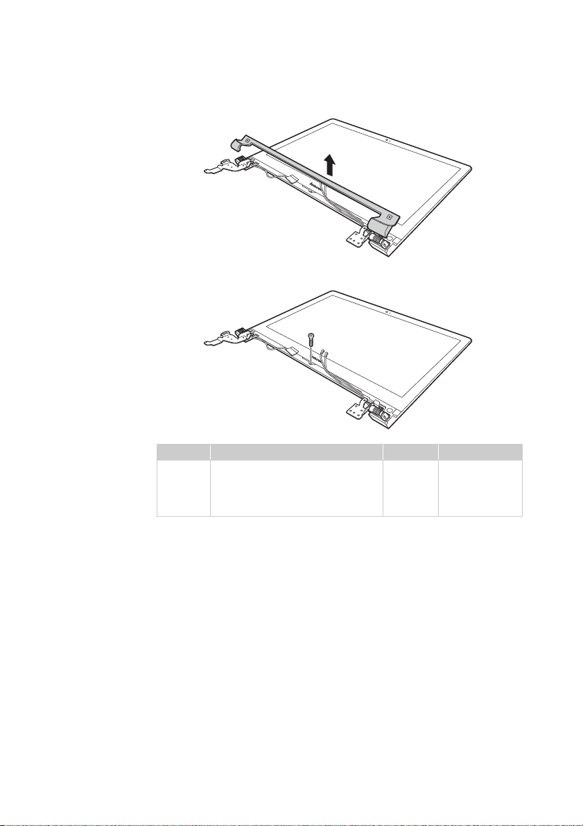
Lenovo Flex 2-14/Flex 2-14D/Flex 2-15/Flex 2-15D
Remove the LCD bezel cover in the direction shown by arrows .
c
Remove screw . Remove the LCD front bezel.
Step Screw (quantity) Color Torque
a
d
d
M2.5 X 4.0 (1) , flat-head,nylokcoated (Flex 2-14/Flex 2-14D)
M2.0 X 3.5 (1) , flat-head,nylokcoated (Flex 2-15/Flex 2-15D)
Silver
Black
c
18~2.0 kgfcm
1.85+/-0.15
kgfcm
65
Page 70
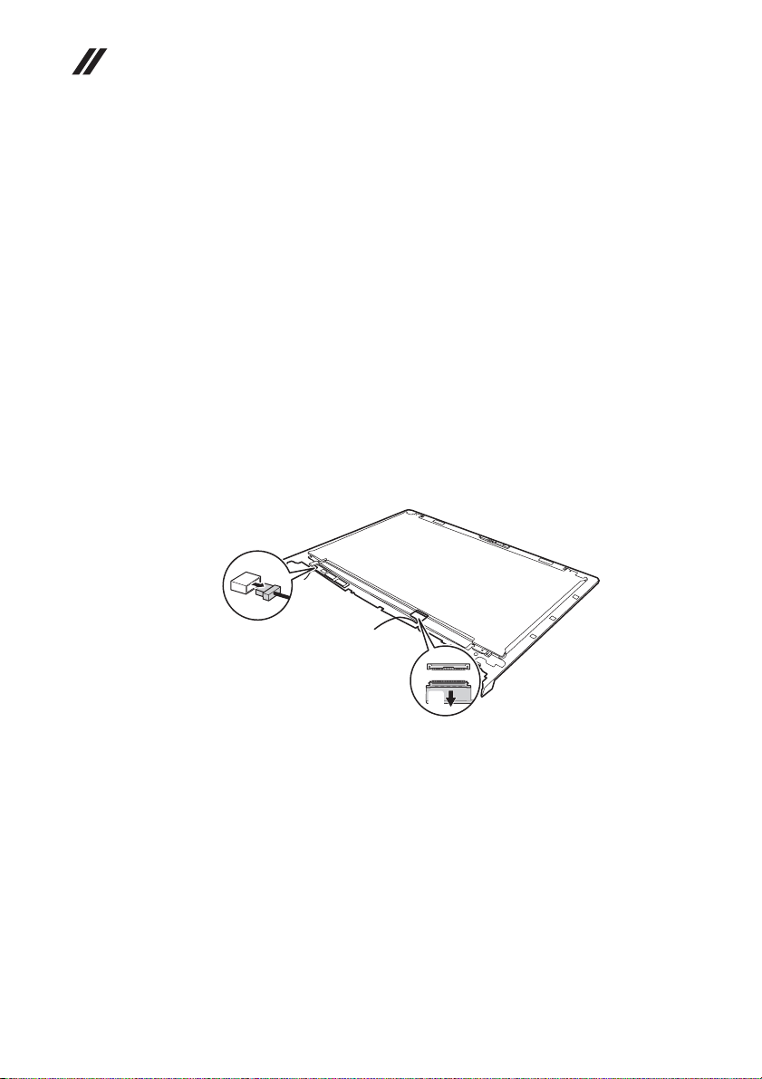
Lenovo Flex 2-14/Flex 2-14D/Flex 2-15/Flex 2-15D Hardware Main-
a
b
tenance Manual
1130 LCD panel, LCD cable and hinges
For access, remove these FRUs in order:
• “1010 Keyboard” on page 34
• “1020 Optical drive” on page 36
• “1030 Hard disk drive(HDD)/Memory/Mini PCI Express Card slot
compartment cover” on page 37
• “1040 Battery pack” on page 39
• “1050 Hard disk drive” on page 40
• “1060 DIMM” on page 42
• “1070 PCI Express Mini Card for wireless LAN/WAN” on page 43
• “1080 Fan assembly and Heat Sink assembly” on page 45
• “1090 System board” on page 49
• “1100 LCD unit” on page 53
• “1110 Speakers, base cover, IO board, DC-IN, power board and ODD transfer
board” on page 56
• “1120 LCD front bezel” on page 64
Figure 13. LCD panel, LCD cable and hinges
Unplug connector , disconnect connector to lift the LCD panel.
a b
When installing: Make sure that the connectors are attached firmly.
66
Page 71
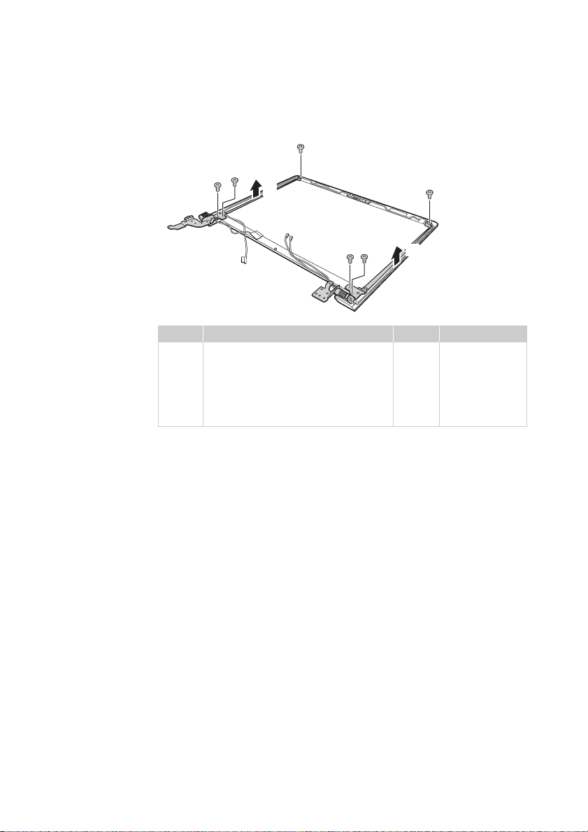
Lenovo Flex 2-14/Flex 2-14D/Flex 2-15/Flex 2-15D
c
Remove four screws , two screws and the hinges in the direction shown
by arrows .
a
Step Screw (quantity) Color Torque
a
M2.0 × 2 mm , flat-head, nylok-coated
(2) (Flex 2-14/Flex 2-14D)
M2.5 × 2.5 mm , flat-head, nylok-coated
(4) (Flex 2-14/Flex 2-14D)
M2.5 × 2.5 mm , flat-head, nylok-coated
(6) (Flex 2-15/Flex 2-15D)
a b
a
c
b
b
a
a
c
Black
Silver
Silver
18~2.0 kgfcm
18~2.0 kgfcm
3.0 +/-0.3 kgfcm
67
Page 72
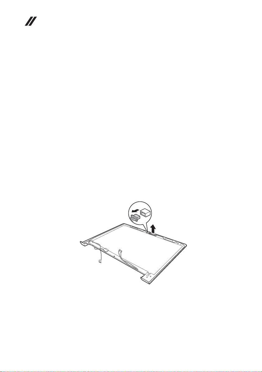
Lenovo Flex 2-14/Flex 2-14D/Flex 2-15/Flex 2-15D Hardware Main-
a
tenance Manual
1140 Integrated camera
For access, remove these FRUs in order:
• “1010 Keyboard” on page 34
• “1020 Optical drive” on page 36
• “1030 Hard disk drive(HDD)/Memory/Mini PCI Express Card slot
compartment cover” on page 37
• “1040 Battery pack” on page 39
• “1050 Hard disk drive” on page 40
• “1060 DIMM” on page 42
• “1070 PCI Express Mini Card for wireless LAN/WAN” on page 43
• “1080 Fan assembly and Heat Sink assembly” on page 45
• “1090 System board” on page 49
• “1100 LCD unit” on page 53
• “1110 Speakers, base cover, IO board, DC-IN, power board and ODD transfer
board” on page 56
• “1120 LCD front bezel” on page 64
• “1130 LCD panel, LCD cable and hinges” on page 66
Figure 14. Removal steps of integrated camera
Note: The integrated camera is stuck on the top center of the LCD cover.
Unplug the connector , remove the integrated camera from the LCD cover in
the direction shown by arrow .
a
b
b
When installing: Stick the integrated camera to the top center of the LCD cover
and adjust the placement of it to make sure the connector is attached firmly.
68
Page 73
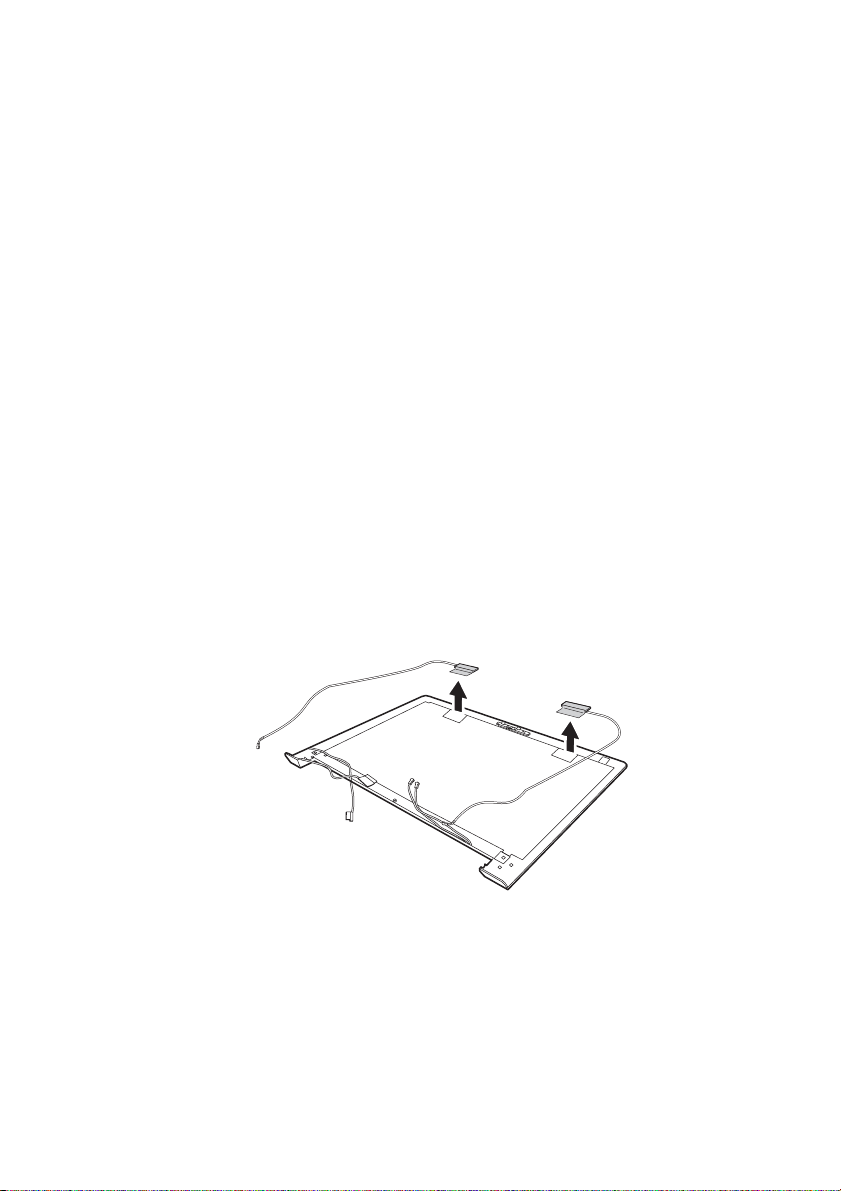
Lenovo Flex 2-14/Flex 2-14D/Flex 2-15/Flex 2-15D
1150 Antenna assembly and LCD cover
For access, remove these FRUs in order:
• “1010 Keyboard” on page 34
• “1020 Optical drive” on page 36
• “1030 Hard disk drive(HDD)/Memory/Mini PCI Express Card slot
compartment cover” on page 37
• “1040 Battery pack” on page 39
• “1050 Hard disk drive” on page 40
• “1060 DIMM” on page 42
• “1070 PCI Express Mini Card for wireless LAN/WAN” on page 43
• “1080 Fan assembly and Heat Sink assembly” on page 45
• “1090 System board” on page 49
• “1100 LCD unit” on page 53
• “1110 Speakers, base cover, IO board, DC-IN, power board and ODD transfer
board” on page 56
• “1120 LCD front bezel” on page 64
• “1130 LCD panel, LCD cable and hinges” on page 66
• “1140 Integrated camera” on page 68
Figure 15. Removal steps of antenna assembly and LCD cover
Peel off the adhesive tapes securing the antenna boards, release the cables from
the cable guide, and then remove the antenna assembly in the direction shown
by arrows .
a
a
a
When installing: Route the antenna cables along the cable guides and secure the
antenna boards with adhesive tapes. As y ou route the cables, make sure that they
are not subjected to any tension. Tension could cause the cables to be damaged
by the cable guides, or a wire to be broken.
69
Page 74
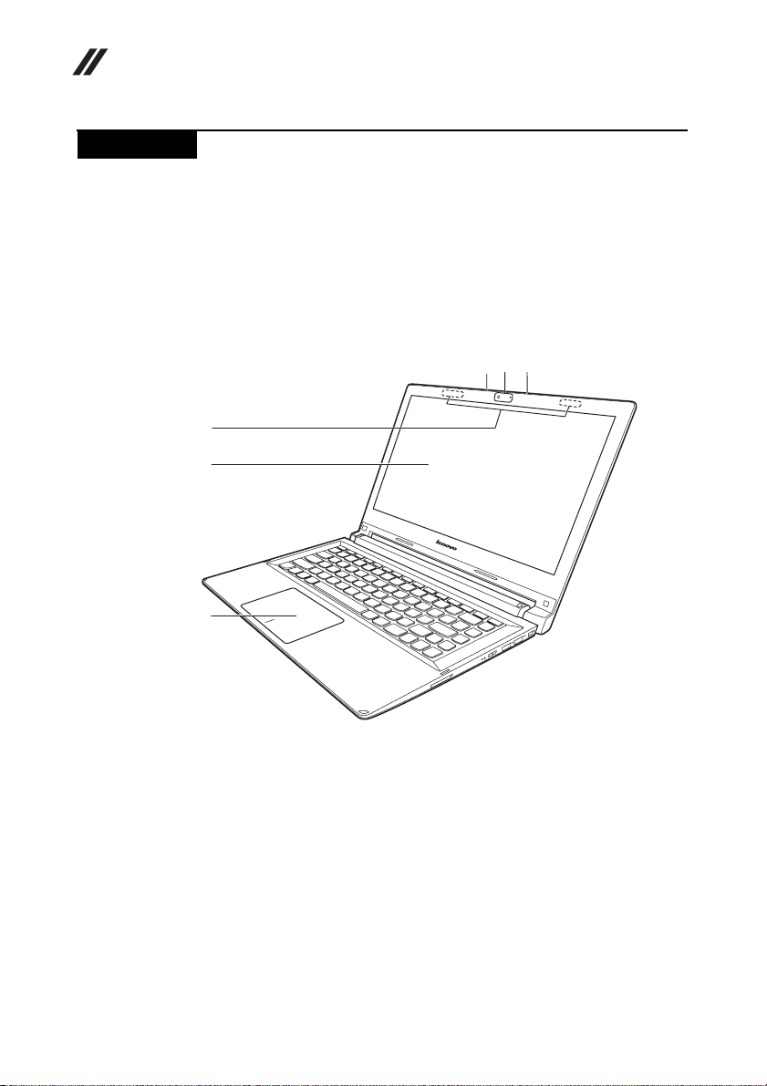
Lenovo Flex 2-14/Flex 2-14D/Flex 2-15/Flex 2-15D Hardware Main-
c
tenance Manual
Locations
Front view
Integrated camera
a
Built-in microphone
b
Wireless antennas
Display
d
Touch pad
e
Numeric keypad (Flex 2-15/Flex 2-15D)
f
Flex 2-14/Flex 2-14D:
b
a
b
c
d
e
70
Page 75
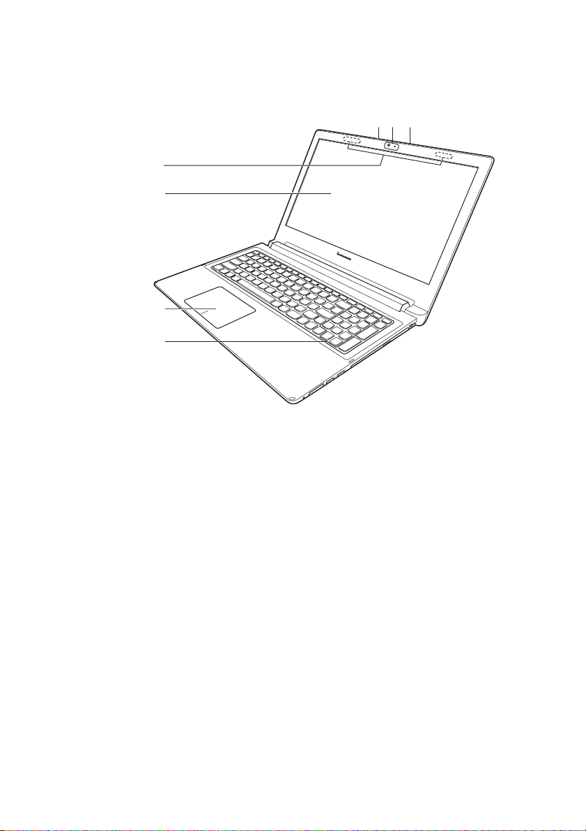
Lenovo Flex 2-14/Flex 2-14D/Flex 2-15/Flex 2-15D
Flex 2-15/Flex 2-15D:
c
d
e
f
b
a
b
71
Page 76
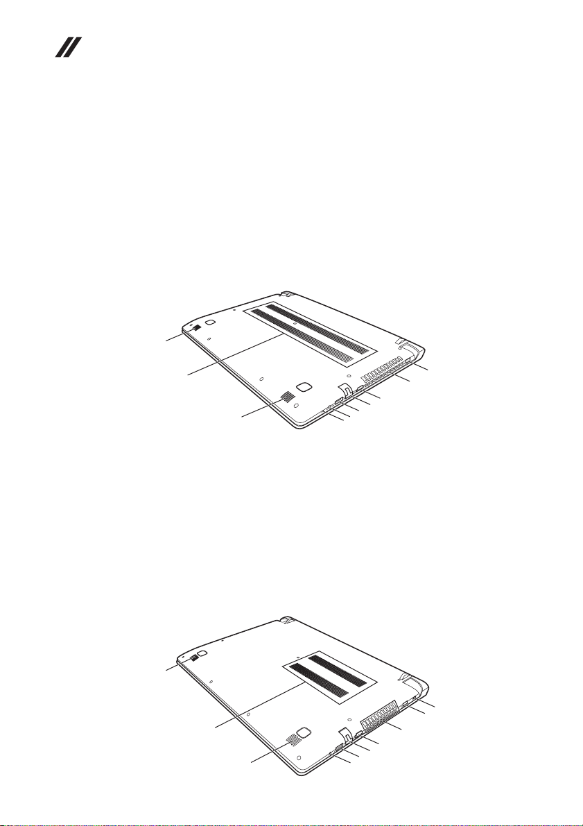
Lenovo Flex 2-14/Flex 2-14D/Flex 2-15/Flex 2-15D Hardware Maintenance Manual
Bottom and Left-side view
Flex 2-14/Flex 2-14D
AC power adapter jack
a
Ventilation slots
b
HDMI port
c
RJ-45 port
d
USB 3.0 port
e
Combo audio jack
f
Novo button
g
Ventilation slots
h
Speakers
i
i
h
i
Flex 2-15/Flex 2-15D
Kensington slot
a
AC power adapter jack
b
Ventilation slots
c
HDMI port
d
RJ-45 port
e
USB 3.0 port
f
Combo audio jack
g
Ventilation slots
h
Speakers
i
i
h
a
b
c
d
e
f
g
a
b
c
d
e
f
i
g
72
Page 77
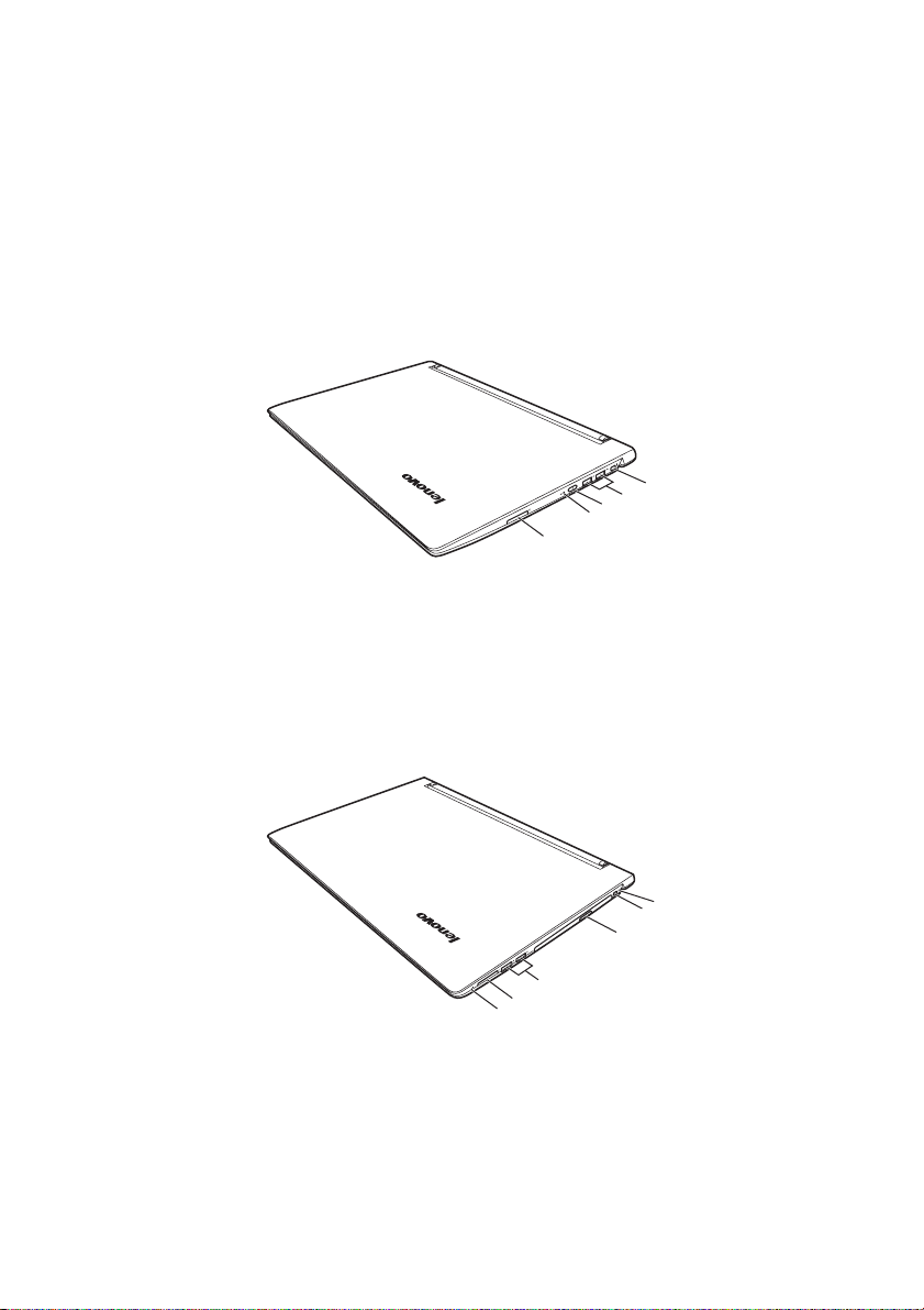
Lenovo Flex 2-14/Flex 2-14D/Flex 2-15/Flex 2-15D
c
d
a
Right-side view
Flex 2-14/Flex 2-14D:
Memory card slot
a
Battery status indicator
b
Power button
c
USB ports
d
Kensington slot
e
Flex 2-15/Flex 2-15D:
Novo button
a
Memory card slot
b
USB ports
Optical disc drive
Power button
e
Battery status indicator
f
e
d
c
b
a
f
e
d
c
b
73
Page 78
Lenovo Flex 2-14/Flex 2-14D/Flex 2-15/Flex 2-15D Hardware Maintenance Manual
Parts list
This section presents the following service parts:
• “Overall” on page 75
• “LCD FRUs” on page 85
• “Keyboard” on page 88
• “Miscellaneous parts” on page 99
• “AC adapters” on page 100
• “Power cords” on page 101
Notes:
• Each FRU is available for all types or models, unless specific types or
models are specified.
74
Page 79
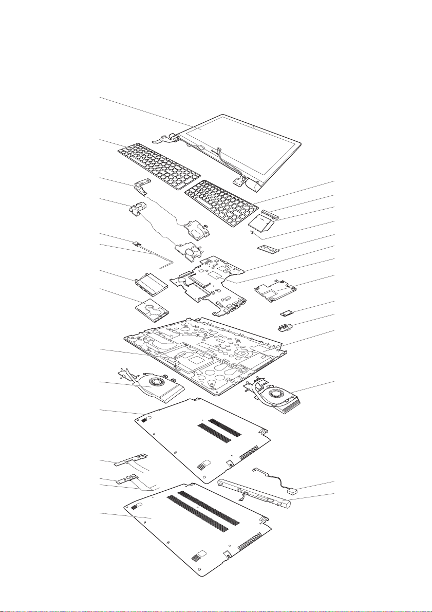
Overall
1
2
Flex 2-15/2-15 D
3
3
5
d
a
10
Lenovo Flex 2-14/Flex 2-14D/Flex 2-15/Flex 2-15D
2
c
Flex 2-14/2-14 D
Flex 2-14/2-14 D
Flex 2-15/2-15 D
4
b
6
7
8
9
11
12
14
e
13
15
16
16
15
Flex 2-14/2-14 D
Flex 2-15/2-15 D
Flex 2-15/2-15 D
Flex 2-14/2-14 D
f
Flex 2-15/2-15 D
Flex 2-14/2-14 D
13
17
18
75
Page 80
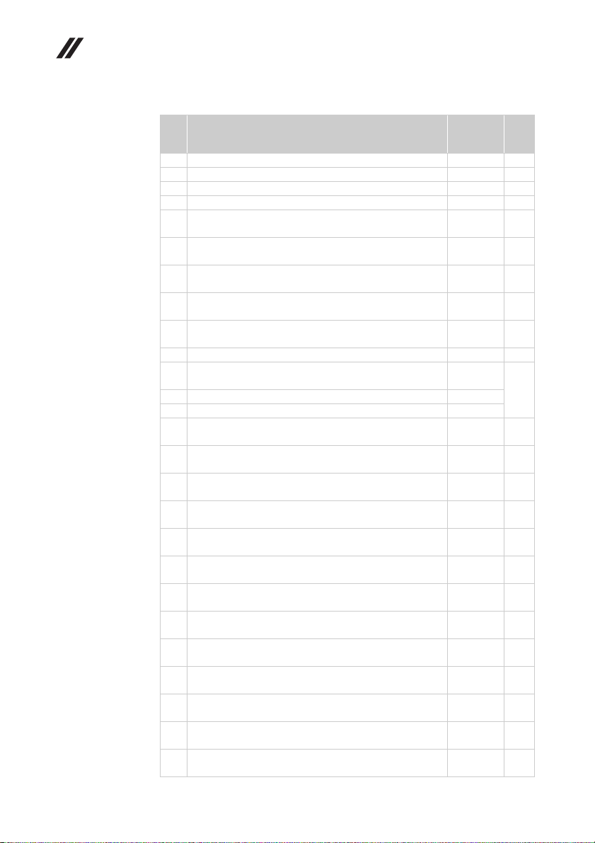
Lenovo Flex 2-14/Flex 2-14D/Flex 2-15/Flex 2-15D Hardware Maintenance Manual
Table 4. Parts list—Overall (continued)
No. FRU FRU no. CRU
1 LCD unit (see “LCD FRUs” on page 73.) N
2 Keyboard (see “Keyboard” on page 75.) **
3 SPEAKERINT Speaker W Flex2-14 (Flex 2-14/Flex 2-14D)
3 SPEAKERINT Speaker W Flex2-15 (Flex 2-15/Flex 2-15D)
4 ODD 9.0 Rambo HLDS GUA0N 9.0 Rambo ODD
(Flex 2-15/Flex 2-15D)
4 ODD 9.0 Rambo PLDS DA-8A5SH 9.0 Rambo ODD
(Flex 2-15/Flex 2-15D)
4 ODD 9.0 Rambo QSI UJ8FBS 9.0 Rambo ODD (Flex 2-15/
Flex 2-15D)
4 ODD 9.0 Rambo TSST SU-228FB 9.0 Rambo ODD
(Flex 2-15/Flex 2-15D)
4 MECHANICAL ODD Dummy W Flex2-15 Black
(Flex 2-15/Flex 2-15D)
4 MECHANICAL ODD Dummy W Flex2-15 Red (Flex 2-15)
5 CARDPOP Power Board W Flex2-15 (Flex 2-15/
Flex 2-15D)
5 CARDPOP Power Board W Flex2-15D (Flex2-15D)
6 DDR3L 1600 2GB SS M471B5674QH0-YK0 2G DDR3L 1600 11202451
6 DDR3L 1600 2GB Hyn HMT425S6AFR6A-PB DDR3L 1600
2GB
6 DDR3L 1600 2GB RMT3170MK58F8F-1600 2GB DDR3L
1600 (MC)
6 DDR3L 1600 2GB MT4KTF25664HZ-1G6E1 2GB DDR3L
1600
6 DDR3L 1600 4GB Hyn HMT451S6AFR8A-PB DDR3L 1600
4GB
6 DDR3L 1600 4GB M471B5173DB0-YK0 25nm 4GB DDR3L
1600
6 DDR3L 1600 4GB SK HMT451S6BFR8A-PB/RD 4GB
DDR3L 1600
6 DDR3L 1600 4GB RMT3170ME68F9F-1600 4GB DDR3L
1600(MC)
6 DDR3L 1600 4GB MC MT8KTF51264HZ-1G6E1 4GB
DDR3L 160
6 DDR3L 1600 8GB Hyn HMT41GS6AFR8A-PB DDR3L 1600
8GB
6 DDR3L 1600 8GB M471B1G73DB0-YK0 25nm 8GB DDR3L
1600
6 DDR3L 1600 8GB SK HMT41GS6BFR8A-PB/RD 8GB
DDR3L 1600
6 DDR3L 1600 8GB RMT3160ME68FAF-1600 8GB DDR3L
1600
6 DDR3L 1600 8GB Mic MT16KTF1G64HZ-1G6E1 DDR3L
1600 8GB
5SB0F76730
5SB0F76735
25215010 **
25213110 **
25215312 **
25215832 **
5M20F76755
5M20F76750
5C50F76769
5C50F78739
11201299 N
11202301 N
11201967 N
11201300 N
11202081 N
11202706 N
11202302 N
11202125 N
11201301 N
11202082 N
11202707 N
11202450 N
11201304 N
ID
N
N
**
**
N
76
Page 81

Lenovo Flex 2-14/Flex 2-14D/Flex 2-15/Flex 2-15D
Table 4. Parts list—Overall (continued)
No. FRU FRU no. CRU
7 BDPLANAR W Flex2-14 2990U UMA (Flex 2-14)
7 BDPLANAR W Flex2-14 W8P 2990U UMA (Flex 2-14)
7 BDPLANAR W Flex2-14 W8S 2990U UMA (Flex 2-14)
7 BDPLANAR W Flex2-14 3558 UMA (Flex 2-14)
7 BDPLANAR W Flex2-14 4010 DIS N15V 2G (Flex 2-14)
7 BDPLANAR W Flex2-14 4010 DIS N15S 2G (Flex 2-14)
7 BDPLANAR W Flex2-14 4200 DIS N15S 2G (Flex 2-14)
7 BDPLANAR W Flex2-14 4010 DIS N15S 4G (Flex 2-14)
7 BDPLANAR W Flex2-14 4200 DIS N15S 4G (Flex 2-14)
7 BDPLANAR W Flex2-14 W8P 3558 UMA (Flex 2-14)
7 BDPLANAR W Flex2-14 W8S 3558 UMA (Flex 2-14)
7 BDPLANAR W Flex2-14 W8P 4010 DIS N15V 2G
(Flex 2-14)
7 BDPLANAR W Flex2-14 W8S 4010 DIS N15V 2G
(Flex 2-14)
7 BDPLANAR W Flex2-14 W8P 4010 DIS N15S 2G
(Flex 2-14)
7 BDPLANAR W Flex2-14 W8S 4010 DIS N15S 2G
(Flex 2-14)
7 BDPLANAR W Flex2-14 W8P 4200 DIS N15S 2G
(Flex 2-14)
7 BDPLANAR W Flex2-14 W8S 4200 DIS N15S 2G
(Flex 2-14)
7 BDPLANAR W Flex2-14 W8P 4010 DIS N15S 4G
(Flex 2-14)
7 BDPLANAR W Flex2-14 W8S 4010 DIS N15S 4G
(Flex 2-14)
7 BDPLANAR W Flex2-14 W8P 4200 DIS N15S 4G
(Flex 2-14)
7 BDPLANAR W Flex2-14 W8S 4200 DIS N15S 4G
(Flex 2-14)
7 BDPLANAR W Flex2-14 4010 UMA (Flex 2-14)
7 BDPLANAR W Flex2-14 W8P 4010 UMA (Flex 2-14)
7 BDPLANAR W Flex2-14 W8S 4010 UMA (Flex 2-14)
7 BDPLANAR W Flex2-14 4200 DIS N15V 2G (Flex 2-14)
7 BDPLANAR W Flex2-14 W8P 4200 DIS N15V 2G
(Flex 2-14)
7 BDPLANAR W Flex2-14 W8S 4200 DIS N15V 2G
(Flex 2-14)
7 BDPLANAR W Flex2-14 4010 UMA (Flex 2-14)
7 BDPLANAR W Flex2-14 W8P 4010 UMA (Flex 2-14)
7 BDPLANAR W Flex2-14 W8S 4010 UMA (Flex 2-14)
7 BDPLANAR W Flex2-14 4200 DIS N15V 2G (Flex 2-14)
7 BDPLANAR W Flex2-14 W8P 4200 DIS N15V 2G
(Flex 2-14)
5B20F76758
5B20F76761
5B20F76762
5B20F84329
5B20F84358
5B20F84331
5B20F84335
5B20F84339
5B20F84342
5B20F84348
5B20F84352
5B20F84356
5B20F84328
5B20F84334
5B20F84340
5B20F84345
5B20F84357
5B20F84330
5B20F84346
5B20F84351
5B20F84354
5B20F85984
5B20F85979
5B20F85980
5B20F85981
5B20F85982
5B20F85968
5B20F86147
5B20F86138
5B20F86136
5B20F86135
5B20F86139
ID
N
N
N
N
N
N
N
N
N
N
N
N
N
N
N
N
N
N
N
N
N
N
N
N
N
N
N
N
N
N
N
N
77
Page 82
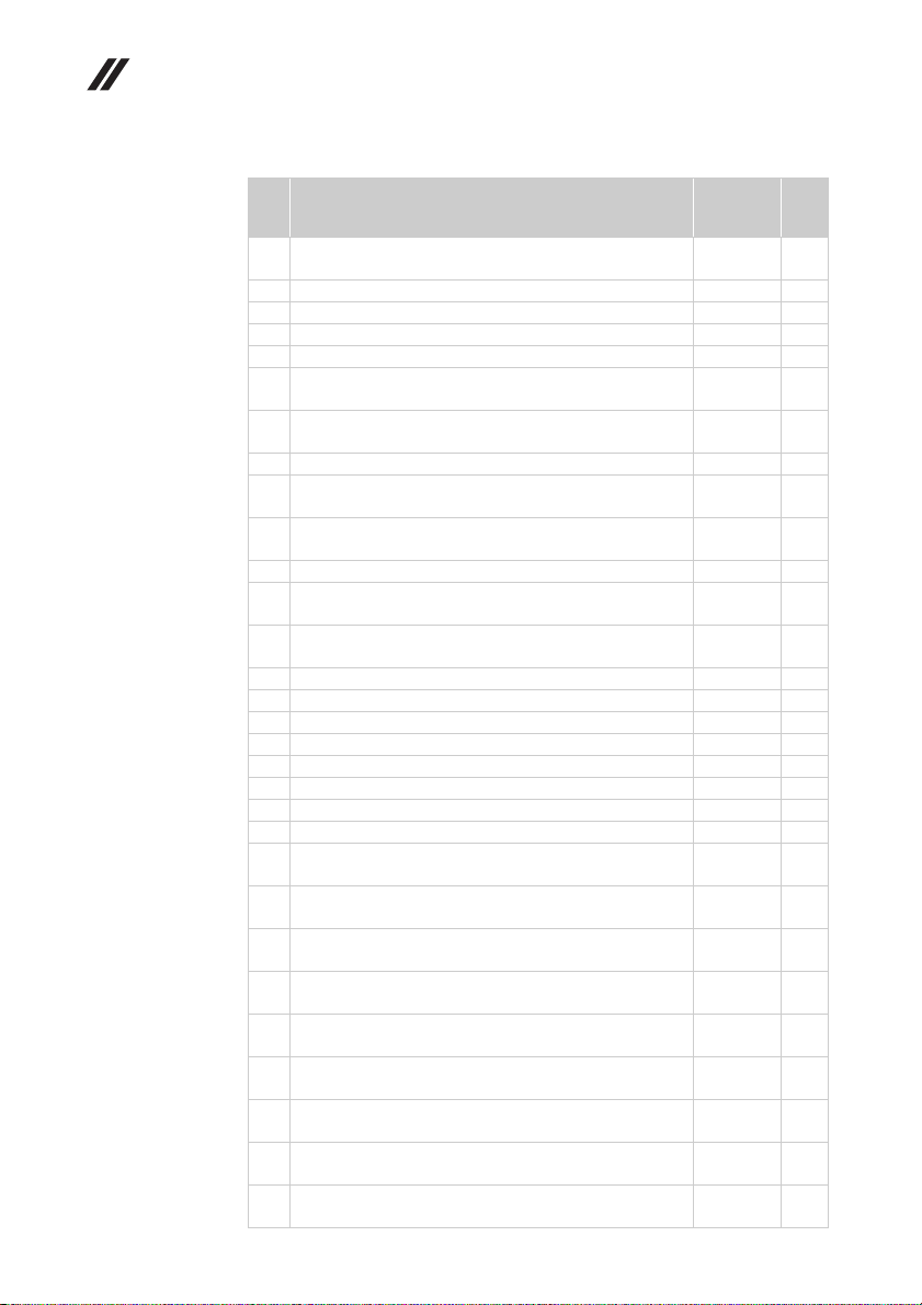
Lenovo Flex 2-14/Flex 2-14D/Flex 2-15/Flex 2-15D Hardware Maintenance Manual
Table 4. Parts list—Overall (continued)
No. FRU FRU no. CRU
7 BDPLANAR W Flex2-14 W8S 4200 DIS N15V 2G
(Flex 2-14)
7 DBPLANNER W Flex2-14 4200 UMA (Flex 2-14)
7 DBPLANNER W Flex2-14 W8P 4200 UMA (Flex 2-14)
7 DBPLANNER W Flex2-14 W8S 4200 UMA (Flex 2-14)
7 DBPLANNER W Flex2-14 4010 DIS N15V 2G (Flex 2-14)
7 DBPLANNER W Flex2-14 W8P 4010 DIS N15V 2G
(Flex 2-14)
7 DBPLANNER W Flex2-14 W8S 4010 DIS N15V 2G
(Flex 2-14)
7 DBPLANNER W Flex2-14 3558 DIS N15V 2G (Flex 2-14)
7 DBPLANNER W Flex2-14 W8P 3558 DIS N15V 2G
(Flex 2-14)
7 DBPLANNER W Flex2-14 W8S 3558 DIS N15V 2G
(Flex 2-14)
7 DBPLANNER W Flex2-14 3558 DIS N15V 2G (Flex 2-14)
7 DBPLANNER W Flex2-14 W8P 3558 DIS N15V 2G
(Flex 2-14)
7 DBPLANNER W Flex2-14 W8S 3558 DIS N15V 2G
(Flex 2-14)
7 BDPLANAR W Flex2-15 3558U UMA (Flex 2-15)
7 BDPLANAR W Flex2-15 W8P 3558U UMA (Flex 2-15)
7 BDPLANAR W Flex2-15 W8S 3558U UMA (Flex 2-15)
7 BDPLANAR W Flex2-15 3558 DIS N15V 2G (Flex 2-15)
7 BDPLANAR W Flex2-15 4010 DIS N15S 2G (Flex 2-15)
7 BDPLANAR W Flex2-15 4200 DIS N15S 2G (Flex 2-15)
7 BDPLANAR W Flex2-15 4010 DIS N15S 4G (Flex 2-15)
7 BDPLANAR W Flex2-15 4200 DIS N15S 4G (Flex 2-15)
7 BDPLANAR W Flex2-15 W8P 3558 DIS N15V 2G
(Flex 2-15)
7 BDPLANAR W Flex2-15 W8S 3558 DIS N15V 2G
(Flex 2-15)
7 BDPLANAR W Flex2-15 W8P 4010 DIS N15S 2G
(Flex 2-15)
7 BDPLANAR W Flex2-15 W8S 4010 DIS N15S 2G
(Flex 2-15)
7 BDPLANAR W Flex2-15 W8P 4200 DIS N15S 2G
(Flex 2-15)
7 BDPLANAR W Flex2-15 W8S 4200 DIS N15S 2G
(Flex 2-15)
7 BDPLANAR W Flex2-15 W8P 4010 DIS N15S 4G
(Flex 2-15)
7 BDPLANAR W Flex2-15 W8S 4010 DIS N15S 4G
(Flex 2-15)
7 BDPLANAR W Flex2-15 W8P 4200 DIS N15S 4G
(Flex 2-15)
5B20F86146
5B20G18398
5B20G18384
5B20G18393
5B20G18387
5B20G18383
5B20G18388
5B20G18381
5B20G18385
5B20G18386
5B20G18389
5B20G18396
5B20G18394
5B20F76798
5B20F76729
5B20F76737
5B20F84327
5B20F84332
5B20F84337
5B20F84341
5B20F84347
5B20F84350
5B20F84355
5B20F84338
5B20F84343
5B20F84349
5B20F84353
5B20F84359
5B20F84333
5B20F84336
ID
N
N
N
N
N
N
N
N
N
N
N
N
N
N
N
N
N
N
N
N
N
N
N
N
N
N
N
N
N
N
78
Page 83

Lenovo Flex 2-14/Flex 2-14D/Flex 2-15/Flex 2-15D
Table 4. Parts list—Overall (continued)
No. FRU FRU no. CRU
7 BDPLANAR W Flex2-15 W8S 4200 DIS N15S 4G
(Flex 2-15)
7 BDPLANAR W Flex2-15 4010 UMA (Flex 2-15)
7 BDPLANAR W Flex2-15 W8P 4010 UMA (Flex 2-15)
7 BDPLANAR W Flex2-15 W8S 4010 UMA (Flex 2-15)
7 BDPLANAR W Flex2-15 4200 UMA (Flex 2-15)
7 BDPLANAR W Flex2-15 W8P 4200 UMA (Flex 2-15)
7 BDPLANAR W Flex2-15 W8S 4200 UMA (Flex 2-15)
7 BDPLANAR W Flex2-15 4010 DIS N15V 2G (Flex 2-15)
7 BDPLANAR W Flex2-15 W8P 4010 DIS N15V 2G
(Flex 2-15)
7 BDPLANAR W Flex2-15 W8S 4010 DIS N15V 2G
(Flex 2-15)
7 BDPLANAR W Flex2-15 4200 DIS N15V 2G (Flex 2-15)
7 BDPLANAR W Flex2-15 W8P 4200 DIS N15V 2G
(Flex 2-15)
7 BDPLANAR W Flex2-15 W8S 4200 DIS N15V 2G
(Flex 2-15)
7 BDPLANAR W Flex2-15 4200 UMA (Flex 2-15)
7 BDPLANAR W Flex2-15 W8P 4200 UMA (Flex 2-15)
7 BDPLANAR W Flex2-15 W8S 4200 UMA (Flex 2-15)
7 BDPLANAR W Flex2-15 4010 DIS N15V 2G (Flex 2-15)
7 BDPLANAR W Flex2-15 W8P 4010 DIS N15V 2G
(Flex 2-15)
7 BDPLANAR W Flex2-15 W8S 4010 DIS N15V 2G
(Flex 2-15)
7 BDPLANAR W Flex2-15 4200 DIS N15V 2G (Flex 2-15)
7 BDPLANAR W Flex2-15 W8P 4200 DIS N15V 2G
(Flex 2-15)
7 BDPLANAR W Flex2-15 W8S 4200 DIS N15V 2G
(Flex 2-15)
7 DBPLANNER W Flex2-15 4010 UMA (Flex 2-15)
7 DBPLANNER W Flex2-15 W8P 4010 UMA (Flex 2-15)
7 DBPLANNER W Flex2-15 W8S 4010 UMA (Flex 2-15)
7 DBPLANNER W Flex2-15 3558 DIS N15V 2G (Flex 2-15)
7 DBPLANNER W Flex2-15 W8P 3558 DIS N15V 2G
(Flex 2-15)
7 DBPLANNER W Flex2-15 W8S 3558 DIS N15V 2G
(Flex 2-15)
7 BDPLANAR W Flex2-14D A6-6400 UMA (Flex 2-14D)
7 BDPLANAR W Flex2-14D W8P A6-6400 UMA
(Flex 2-14D)
7 BDPLANAR W Flex2-14D W8S A6-6400 UMA
(Flex 2-14D)
7 BDPLANAR W Flex2-14D E1-6010 UMA (Flex 2-14D)
5B20F84344
5B20F85970
5B20F85971
5B20F85972
5B20F85973
5B20F85974
5B20F85975
5B20F85977
5B20F85983
5B20F85985
5B20F85969
5B20F85976
5B20F85978
5B20F86145
5B20F86142
5B20F86140
5B20F86141
5B20F86144
5B20F86148
5B20F86134
5B20F86137
5B20F86143
5B20G18395
5B20G18382
5B20G18392
5B20G18391
5B20G18390
5B20G18397
5B20F78748
5B20F78752
5B20F78740
5B20G00843
ID
N
N
N
N
N
N
N
N
N
N
N
N
N
N
N
N
N
N
N
N
N
N
N
N
N
N
N
N
N
N
N
N
79
Page 84
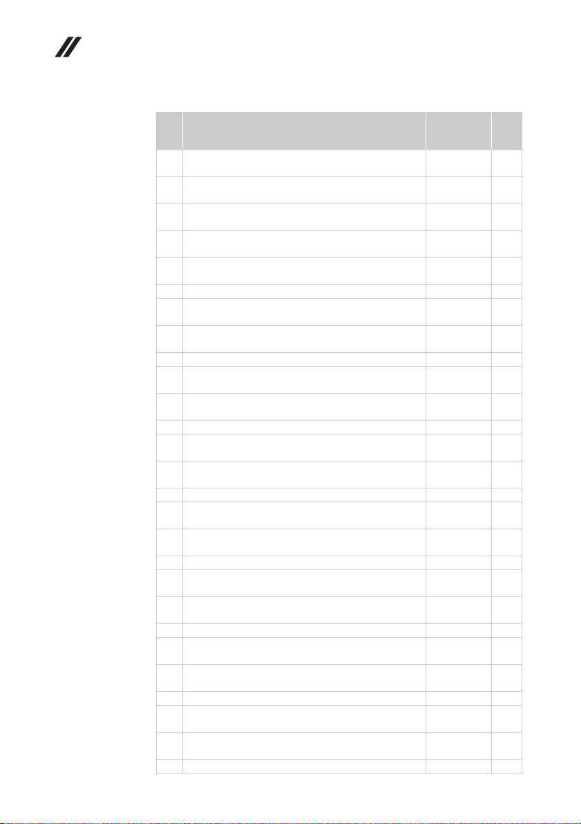
Lenovo Flex 2-14/Flex 2-14D/Flex 2-15/Flex 2-15D Hardware Maintenance Manual
Table 4. Parts list—Overall
No. FRU FRU no. CRU
7 BDPLANAR W Flex2-14D W8P E1-6010 UMA
(Flex 2-14D)
7 BDPLANAR W Flex2-14D W8S E1-6010 UMA
(Flex 2-14D)
7 BDPLANAR W Flex2-14D A6-6310 DIS 1G
(Flex 2-14D)
7 BDPLANAR W Flex2-14D W8P A6-6310 DIS 1G
(Flex 2-14D)
7 BDPLANAR W Flex2-14D W8S A6-6310 DIS 1G
(Flex 2-14D)
7 BDPLANAR W Flex2-14D A4-6210 DIS 2G (Flex 2-14D)
7 BDPLANAR W Flex2-14D W8P A4-6210 DIS 2G
(Flex 2-14D)
7 BDPLANAR W Flex2-14D W8S A4-6210 DIS 2G
(Flex 2-14D)
7 BDPLANAR W Flex2-14D A6-6310 DIS 2G (Flex 2-14D)
7 BDPLANAR W Flex2-14D W8P A6-6310 DIS 2G
(Flex 2-14D)
7 BDPLANAR W Flex2-14D W8S A6-6310 DIS 2G
(Flex 2-14D)
7 BDPLANAR W Flex2-14D A6-6310 UMA (Flex 2-14D)
7 BDPLANAR W Flex2-14D W8P A6-6310 UMA
(Flex 2-14D)
7 BDPLANAR W Flex2-14D W8S A6-6310 UMA
(Flex 2-14D)
7 BDPLANAR W Flex2-15D A6-6400 UMA (Flex 2-15D)
7 BDPLANAR W Flex2-15D W8P A6-6400 UMA
(Flex 2-15D)
7 BDPLANAR W Flex2-15D W8S A6-6400 UMA
(Flex 2-15D)
7 BDPLANAR W Flex2-15D E1-6010 UMA (Flex 2-15D)
7 BDPLANAR W Flex2-15D W8P E1-6010 UMA
(Flex 2-15D)
7 BDPLANAR W Flex2-15D W8P E1-6010 UMA
(Flex 2-15D)
7 BDPLANAR W Flex2-15D A8-6410 UMA (Flex 2-15D)
7 BDPLANAR W Flex2-15D W8P A8-6410 UMA
(Flex 2-15D)
7 BDPLANAR W Flex2-15D W8S A8-6410 UMA
(Flex 2-15D)
7 BDPLANAR W Flex2-15D A6-6310 DIS 1G (Flex 2-15D)
7 BDPLANAR W Flex2-15D W8P A6-6310 DIS 1G
(Flex 2-15D)
7 BDPLANAR W Flex2-15D W8S A6-6310 DIS 1G
(Flex 2-15D)
7 BDPLANAR W Flex2-15D A6-6310 UMA (Flex 2-15D)
5B20G00839
5B20G00845
5B20G00849
5B20G00855
5B20G00840
5B20G00847
5B20G00852
5B20G00836
5B20G00842
5B20G00848
5B20G00853
5B20G16326
5B20G16328
5B20G16327
5B20F78746
5B20F78751
5B20F78747
5B20G00838
5B20G00851
5B20G00856
5B20G00841
5B20G00846
5B20G00850
5B20G00854
5B20G00837
5B20G00844
5B20G16323
ID
N
N
N
N
N
N
N
N
N
N
N
N
N
N
N
N
N
N
N
N
N
N
N
N
N
N
N
80
Page 85

Lenovo Flex 2-14/Flex 2-14D/Flex 2-15/Flex 2-15D
Table 4. Parts list—Overall (continued)
No. FRU FRU no. CRU
7 BDPLANAR W Flex2-15D W8P A6-6310 UMA
(Flex 2-15D)
7 BDPLANAR W Flex2-15D W8S A6-6310 UMA
(Flex 2-15D)
7 BDPLANAR W Flex2-15D A6-6310 DIS 2G (Flex 2-15D)
7 BDPLANAR W Flex2-15D W8P A6-6310 DIS 2G
(Flex 2-15D)
7 BDPLANAR W Flex2-15D W8S A6-6310 DIS 2G
(Flex 2-15D)
8 CPU Haswell ULT Intel I5-4200U 1.6G 3M C0 2cBGA
CPU (Flex 2-14/Flex 2-15)
8 CPU Haswell Intel I3-4010U 1.7G 3M C0 2cBGA CPU
(Flex 2-14/Flex 2-15)
8 CPU Haswell Intel 3558U 1.7G 2M D0 2cBGA CPU
(Flex 2-14/Flex 2-15)
8 CPU Haswell Intel 2990U 1.7G 2M D0 2cBGA CPU
(Flex 2-14/Flex 2-15)
8 CPU Haswell Intel i3-4025U 1.9G 3M D0 2cBGA CPU
(Flex 2-14/Flex 2-15)
8 CPU Haswell Intel i3-4030U 1.9G 3M D0 2cBGA CPU
(Flex 2-14/Flex 2-15)
8 CPU Haswell Intel i5-4210U 1.7G 3M D0 2cBGA CPU
(Flex 2-14/Flex 2-15)
8 CPU Haswell Intel i7-4510U 2G 4M D0 2cBGA CPU
(Flex 2-14/Flex 2-15)
8 CPU Haswell Intel 2957U 1.4G 2M D0 2cBGA CPU
(Flex 2-14/Flex 2-15)
8 CPU Bay-trial-M Intel N3520 2.17G 2M B3 4cBGA CPU
(Flex 2-14/Flex 2-15)
8 CPU Bay-trial-M Intel N2920 1.86G 2M B3 4cBGA CPU
(Flex 2-14/Flex 2-15)
8 CPU Bay-trial-M Intel N2815 1.86G 1M B3 2cBGA CPU
(Flex 2-14/Flex 2-15)
8 CPU Bay-trial-M Intel N2806 1.6G 1M B3 2cBGA CPU
(Flex 2-14/Flex 2-15)
8 CPU Bay-trial-M Intel N2830 2.17G 1M C0 2cBGA CPU
(Flex 2-14/Flex 2-15)
8 CPU Bay-trial-M Intel N2930 1.83G 2M C0 4cBGA CPU
(Flex 2-14/Flex 2-15)
8 CPU Bay-trial-M Intel N3530 2.17G 2M C0 4cBGA CPU
(Flex 2-14/Flex 2-15)
8 CPU Beama AMD A6-6310 1.8G 2M 4cBGA APU
(Flex 2-14D/Flex 2-15D)
8 CPU Beama AMD A4-6210 1.8G 2M 4cBGA APU
(Flex 2-14D/Flex 2-15D)
8 CPU Beama AMD E2-6110 1.5G 2M 4cBGA APU
(Flex 2-14D/Flex 2-15D)
5B20G16322
5B20G16329
5B20G16330
5B20G16325
5B20G16324
102500568 N
102500569 N
102500685 N
102500732 N
5SA0F75458
5SA0F75450
102500736 N
102500737 N
102500687 N
102500678 N
102500679 N
102500681 N
102500682 N
5SA0F63347
5SA0F63351
5SA0F63344
102500690 N
102500691 N
102500692 N
ID
N
N
N
N
N
N
N
N
N
N
81
Page 86

Lenovo Flex 2-14/Flex 2-14D/Flex 2-15/Flex 2-15D Hardware Maintenance Manual
Table 4. Parts list—Overall (continued)
82
No. FRU FRU no. CRU
8 CPU Beama AMD E1-6010 1.35G 1M 2cBGA APU
(Flex 2-14D/Flex 2-15D)
8 CPU Beama AMD A8-6410 2.0G 2M 4cBG APU
(Flex 2-14D/Flex 2-15D)
9 SPEAKERINT Woofer W Flex2-14
10 HDD 320g 5400rpm(7mm) ST320LT012 6G 7mm 5.4K
320G HDD
10 HDD 320g 5400rpm(7mm) TSB MQ01ABF032 6G 7mm
5.4K 320G HDD (Flex 2-14/Flex 2-15)
10 HDD 320g 5400rpm(7mm) WD3200LPCX-24C6HT0 6G
7mm 5.4K 320G HDD
10 HDD 320g 5400rpm(7mm) HTS545032A7E660 6G 7mm
5.4K 320G HDD
10 HDD 500G 5400rpm(7mm) ST500LT012 6G 7mm 5.4K
500G HDD
10 HDD 500G 5400rpm(7mm) WD5000LPCX-24C6HT0 6G
7mm 5.4K 500G HDD
10 HDD 500G 5400rpm(7mm) TSB MQ01ABF050 6G 7mm
5.4K 500G HDD
10 HDD 500G 5400rpm(7mm) HTS545050A7E660 6G 7mm
5.4K 500G HDD
10 HDD 1TB 5400rpm(7mm) HTS541010A7E630 7mm
5400rpm 1T HDD
10 HDD 1TB 5400rpm(7mm) Seagate Angsana 7.0mm
2D(6G) 1TB
10 HDD 1TB 5400rpm(7mm) WD10SPCX-24HWST0 6G
7mm 1T HDD
10 SSD(Not used in Baytrial) 128GB 2.5" Sata SS
MZ7TE128HMGR 128G 2.5" SSD (Flex 2-14/Flex 2-15)
10 SSD(Not used in Baytrial) 128GB 2.5" Sata SS
MZ7TE128HMGR128GB 2.5'' (Flex 2-14/Flex 2-15)
10 SSD(Not used in Baytrial) 128GB 2.5" Sata Lite-on LCS-
128M6S 128G SATA SSD(Flex 2-14/Flex 2-15)
10 SSD(Not used in Baytrial) 256GB 2.5'' Sata SS
MZ7TE256HMHP 256G 2.5" SSD(Flex 2-14/Flex 2-15)
10 SSD(Not used in Baytrial) 256GB 2.5'' Sata SS
MZ7TE256HMHP 256GB 2.5''(Flex 2-14/Flex 2-15)
10 SSD(Not used in Baytrial) 256GB 2.5'' Sata Lite-on LCS-
256M6S 256GB SATA SSD(Flex 2-14/Flex 2-15)
10 SSD 128GB 2.5" Sata SS MZ7TE128HMGR 128G 2.5"
SSD(Flex 2-14D/Flex 2-15D)
10 SSD 128GB 2.5" Sata SS MZ7TE128HMGR128GB 2.5''
(Flex 2-14D/Flex 2-15D)
10 SSD 128GB 2.5" Sata Lite-on LCS-128M6S 128G SATA
SSD(Flex 2-14D/Flex 2-15D)
10 SSD 256GB 2.5'' Sata SS MZ7TE256HMHP 256G 2.5"
SSD(Flex 2-14D/Flex 2-15D)
102500694 N
5SA0F63345
5SB0F76768
16200384 N
16200434 N
16200551 N
16200405 N
16200383 N
16200395 N
16200433 N
16200404
16200658 N
16200660 N
16200554 N
16200604 N
5SD0F76812
16200352 N
16200605 N
5SD0F76811
16200488 N
16200604 N
5SD0F76812
16200352 N
16200605 N
ID
N
N
N
N
N
N
Page 87

Lenovo Flex 2-14/Flex 2-14D/Flex 2-15/Flex 2-15D
Table 4. Parts list—Overall (continued)
No. FRU FRU no. CRU
10 SSD 256GB 2.5'' Sata SS MZ7TE256HMHP 256GB 2.5''
(Flex 2-14D/Flex 2-15D)
10 SSD 256GB 2.5'' Sata Lite-on LCS-256M6S 256GB SATA
SSD (Flex 2-14D/Flex 2-15D)
10 e MMC (Only used in Baytrial) eMMC 16G Samsung
KLMAG2GEAC EMMC 16G SSD (Flex 2-14/Flex 2-15)
10 e MMC (Only used in Baytrial) eMMC 16G Sandisk
SDIN8DE4 EMMC 16G SSD (Flex 2-14/Flex 2-15)
10 e MMC (Only used in Baytrial) eMMC 32G Samsung
KLMBG4GEAC EMMC 32G SSD (Flex 2-14/Flex 2-15)
10 e MMC (Only used in Baytrial) eMMC 32G Sandisk
SDIN8DE4-32G EMMC 32G SSD (Flex 2-14/Flex 2-15)
10 SSHD 500 +8G Hybrid(7mm) ST500LM000 6G 7mm
500G+8G SSHD
10 SSHD 500 +8G Hybrid(7mm) MN500Sh-2 7mm
500G+8G SSHD
10 SSHD 1T +8G Hybrid(7mm) MN500Mh-2 7mm 1TB+8G
SSHD
11 WLAN Intel 1x1 AC+BT 4.0/WiDi Intel 3160 1x1AC+BT
PCIE NGFF WLAN (Flex 2-14/Flex 2-15)
11 WLAN Non-Intel 1x1 BN+BT 4.0 Ltn NFA335
1x1BN+BT4.0 PCIE M.2 WLAN
11 WLAN Non-Intel 1x1 BN+BT 4.0 Cbt BCM43142
1x1BN+BT4.0 PCIE M.2 WLAN
11 WLAN Non-Intel 1x1 BN+BT 4.0 Cbt RTL8723BE
1x1BN+BT4.0 PCIE M.2 WLAN
11 WLAN Non-intel 1x1 AC +BT 4.0 Ltn NFA345
1x1AC+BT4.0 PCIE M.2 WLAN
11 WLAN Non-intel 1x1 AC +BT 4.0 Cbt BCM43162
1x1AC+BT4.0 PCIE M.2 WLAN
12 CARDPOP ODD Board W Flex2-15 W/Cable
(Flex 2-15/Flex 2-15D)
12 CARDPOP ODD Board W Flex2-15D W/Cable
(Flex 2-15D)
14 COVER Upper Case W Flex2-14 Grey (Flex 2-14)
14 COVER Upper Case W Flex2-14 Red (Flex 2-14)
14 COVER Upper Case W Flex2-14 White (Flex 2-14/
Flex 2-14D)
14 COVER Upper Case W Flex2-14 Black (Flex 2-14/
Flex 2-14D)
14 COVER Upper Case W Flex2-14 Red (Flex 2-14)
14 COVER Upper Case W Flex2-14 Yellow (Flex 2-14/
Flex 2-14D)
14 COVER Upper Case W Flex2-15 Black (Flex 2-15/
Flex 2-15D)
14 COVER Upper Case W Flex2-15 Red (Flex 2-15)
5SD0F76811
16200488 N
16200565 N
16200564 N
16200447 N
16200556 N
16200391 N
16200680 N
16200681
20200418 N
20200558 N
20200557 N
20200570 N
20200579 N
20200573 N
5C50F76766
5C50F78744
5CB0F76760
5CB0F76754
5CB0F76759
5CB0F76756
5CB0F76754
5CB0F76751
5CB0F76796
5CB0F76791
ID
N
N
N
N
N
N
N
N
N
N
N
N
83
Page 88

Lenovo Flex 2-14/Flex 2-14D/Flex 2-15/Flex 2-15D Hardware Maintenance Manual
Table 4. Parts list—Overall (continued)
No. FRU FRU no. CRU
15 COVER Lower Case W Flex2-14 Grey (Flex 2-14)
15 COVER Lower Case W Flex2-14 White (Flex 2-14/
Flex 2-14D)
15 COVER Lower Case W Flex2-14 Black (Flex 2-14/
Flex 2-14D)
15 COVER Lower Case W Flex2-14 Red (Flex 2-14)
15 COVER Lower Case W Flex2-14 Yellow (Flex 2-14/
Flex 2-14D)
15 COVER Lower Case W Flex2-15 Black (Flex 2-15/
Flex 2-15D)
15 COVER Lower Case W Flex2-15 Red (Flex 2-15)
16 CARDPOP IO Board W Flex2-14 (Flex 2-14/Flex 2-14D)
16 CARDPOP IO Board W Flex2-15 (Flex 2-15/Flex 2-15D)
16 CARDPOP IO Board W Flex2-14D (Flex 2-14D)
16 CARDPOP IO Board W Flex2-15D
17 CABLE DC-IN W Flex2-14
17 CABLE DC-IN W Flex2-15
17 CABLE DC-IN W Flex2-14D
17 CABLE DC-IN W Flex2-15D
18 Battery 18650 2.8Ah 4 cell Mybo SY L13S4E61
7.2V41.6Wh 4cell bty
18 Battery 18650 2.8Ah 4 cell Mybo SP/L L13M4E61
7.44V41.6Wh 4cell bty
18 Battery 18650 2.8Ah 4 cell Mybo LG L13L4E61
7.44V41.6Wh 4cell bty
18 18 Battery 18650 2.2Ah 4 cell Mybo SY L13S4A61
7.2V32Wh 4cell bty
18 Battery 18650 2.2Ah 4 cell Mybo SP/L L13M4A61
7.2V32Wh 4cell bty
18 Battery 18650 2.2Ah 4 cell Mybo LG L13L4A61
7.2V32Wh 4cell bty
5CB0F76741
5CB0F76738
5CB0F76736
5CB0F76733
5CB0F76731
5CB0F76746
5CB0F76790
5C50F76784
5C50F76764
5C50F78738
5C50F78741
5C10F76770
5C10F84514
5C10F78745
5C10G00126
121500245 N
121500246 N
121500247 N
121500260 N
121500261 N
121500262 N
ID
N
N
N
N
N
N
N
N
N
N
N
N
N
N
N
84
Page 89
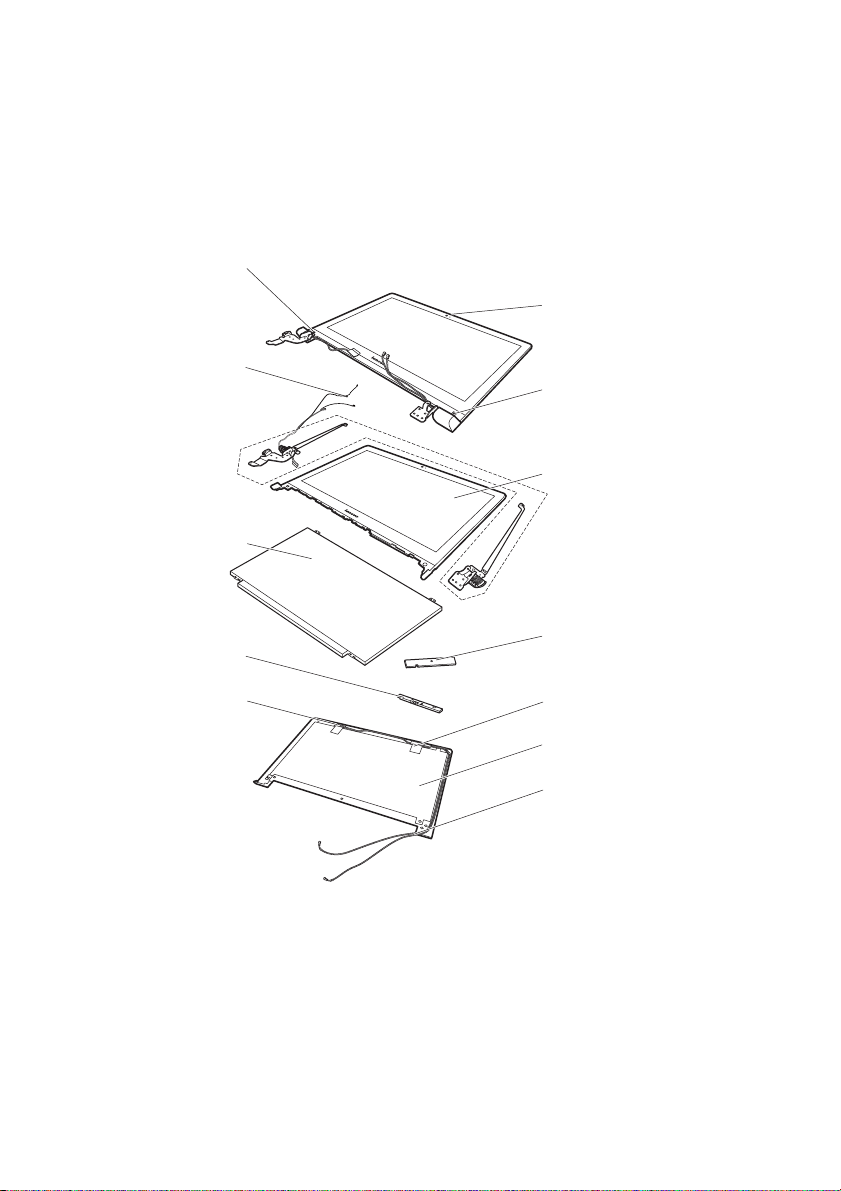
Lenovo Flex 2-14/Flex 2-14D/Flex 2-15/Flex 2-15D
LCD FRUs
In Lenovo Flex 2-14/Flex 2-14D/Flex 2-15/Flex 2-15D, there are following types
of LCDs.
• “14.0 -in. HD TFT”
• “15.6 -in. HD TFT”
2
1
4
2
3
5
7
8
6
6
9
6
85
Page 90
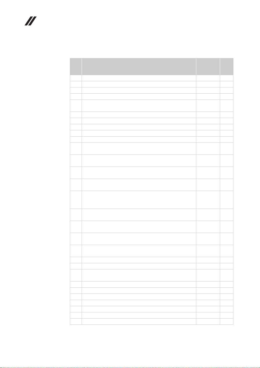
Lenovo Flex 2-14/Flex 2-14D/Flex 2-15/Flex 2-15D Hardware Maintenance Manual
14.0-in. HD TFT
Table 5. Parts list—14.0-in. HD TFT
No. FRU FRU no. CRU
1 DISPLAY LCD Module W Flex2-14 Grey (Flex2-14)
1 DISPLAY LCD Module W Flex2-14 Black FHD (Flex2-14)
1 DISPLAY LCD Module W Flex2-14 Grey FHD (Flex2-14)
1 DISPLAY LCD Module W Flex2-14D Black (Flex 2-14D)
2 RUBBER LCD Bezel Screw Pad W Flex2-14 (Flex 2-14/
Flex 2-14D)
3 BEZEL LCD W Flex2-14 White (Flex 2-14/Flex 2-14D)
3 BEZEL LCD W Flex2-14 Grey (Flex2-14)
3 BEZEL LCD W Flex2-14 Black (Flex 2-14/Flex 2-14D)
3 BEZEL LCD W Flex2-14 Red (Flex2-14)
3 BEZEL LCD W Flex2-14 Yellow (Flex 2-14/Flex 2-14D)
4 HINGE L+R W Flex2-14 W/LCD&Camera Cable
(Flex 2-14/Flex 2-14D)
5 Panel 14.0 Edp HD TN 3.0 mm Slim LGD LP140WHU-
TPBH HD AG S LED1 NB LCD (Flex2-14)
5 Panel 14.0 Edp HD TN 3.0 mm Slim AUO B140XTN02.A
HW0A HD AG S LED1 NB LCD (Flex2-14)
5 Panel 14.0 Edp HD TN 3.0 mm Slim CMI N140BGE-EA3
C2 HD AG S LED1 NB LCD (Flex2-14)
5 Panel 14.0 Edp FHD IPS AG 3.0mm Slim (Not used in
Baytrial) LGD LP140WF3-SPL1 FHD AG S LED1 NB LCD
(Flex2-14)
5 Panel 14.0 Edp HD 3.0 mm Slim LGD LP140WHU-TPB3
HD AG S LED1 NB LCD (Flex2-14D)
5 Panel 14.0 Edp HD 3.0 mm Slim AUO B140XTN02.A
HW0A HD AG S LED1 NB LCD (Flex2-14D)
5 Panel 14.0 Edp HD 3.0 mm Slim CMI N140BGE-EA3 C2
HD AG S LED1 NB LCD (Flex2-14D)
6 ANTENNA WLAN W Flex2-14 MAIN/AUX (Flex 2-14/
Flex 2-14D)
7 CARDPOP Sensor Board W Flex2-14 (Flex2-14)
7 CARDPOP Sensor Board W Flex2-14D (Flex2-14D)
8 CAMERA W Flex2-14 0.3M W/1MIC (Flex 2-14/
Flex 2-14D)
8 CAMERA W Flex2-14 1M W/1MIC (Flex 2-14/Flex 2-14D)
8 CAMERA W Flex2-14 1M W/2MIC (Flex 2-14/Flex 2-14D)
9 COVER LCD W Flex2-14 White (Flex 2-14/Flex 2-14D)
9 COVER LCD W Flex2-14 Black (Flex 2-14/Flex 2-14D)
9 COVER LCD W Flex2-14 Grey (Flex2-14)
9 COVER LCD W Flex2-14 Red (Flex2-14)
9 COVER LCD W Flex2-14 Yellow (Flex 2-14/Flex 2-14D)
5D10F76748
5D10F86070
5D10F86069
5D10G18360
5R60F76763
5B30F76779
5B30F76772
5B30F76771
5B30F76783
5B30F76782
5H50F76734
18201582 N
18201154 N
18201578 N
18201637 N
18201582 N
18201154 N
18201578 N
5A30F76752
5C50F76743
5C50F78750
5C20F76774
5C20F76777
5C20F76778
5CB0F76780
5CB0F76776
5CB0F76786
5CB0F76785
5CB0F76781
ID
N
N
N
N
N
N
N
N
N
N
N
N
N
N
N
N
N
N
N
N
N
N
86
Page 91

Lenovo Flex 2-14/Flex 2-14D/Flex 2-15/Flex 2-15D
15.6-in. HD TFT
Table 6. Parts list—15.6-in. HD TFT
No. FRU FRU no. CRU
1 DISPLAY LCD Module W Flex2-15 Black FHD (Flex 2-15)
1 DISPLAY LCD Module W Flex2-15D Black (Flex 2-15D)
2 RUBBER LCD Bezel Screw Pad W Flex2-15 (Flex 2-15/
Flex 2-15D)
3 BEZEL LCD W Flex2-15 Black (Flex 2-15/Flex 2-15D)
3 BEZEL LCD W Flex2-15 Red (Flex 2-15)
4 HINGE L+R W Flex2-15 W/LCD&Camera Cable
(Flex 2-15/Flex 2-15D)
5 LCD Panel 15.6 Edp HD AG 3.0mm Slim LGD
LP156WHU TPB2 HD AG S LED1 LCD
5 LCD Panel 15.6 Edp HD AG 3.0mm Slim AUO
B156XTN03.5 4A HD AG S LED1 LCD
5 LCD Panel 15.6 Edp HD AG 3.0mm Slim CMI N156BGE-
EA1 C2 HD AG S LED1 NB LCD
5 LC D Pa nel1 5.6 Ed p FH D IPS AG 3.0 mm Sl im (Not use d i n
Baytrial) LGD LP156WF4-SPL1 FHD AG S LED1 NB LCD
(Flex 2-15)
6 ANTENNA WLAN W Flex2-15 MAIN/AUX (Flex 2-15/
Flex 2-15D)
7 CARDPOP Sensor Board W Flex2-15 (Flex 2-15)
7 CARDPOP Sensor Board W Flex2-15D (Flex 2-15D)
8 CAMERA W Flex2-14 0.3M W/1MIC (Flex 2-15/
Flex 2-15D)
8 CAMERA W Flex2-14 1M W/1MIC (Flex 2-15/Flex 2-15D)
8 CAMERA W Flex2-14 1M W/2MIC (Flex 2-15/Flex 2-15D)
9 COVER LCD W Flex2-15 Black (Flex 2-15/Flex 2-15D)
9 COVER LCD W Flex2-15 Red (Flex 2-15)
5D10F86071
5D10G18359
5R60F76742
5B30F76747
5B30F76793
5H50F76792
18201590 N
18201591 N
18201589 N
18201638 N
5A30F76795
5C50F76765
5C50F78743
5C20F76774
5C20F76777
5C20F76778
5CB0F76749
5CB0F76797
ID
N
N
N
N
N
N
N
N
N
N
N
N
N
N
87
Page 92
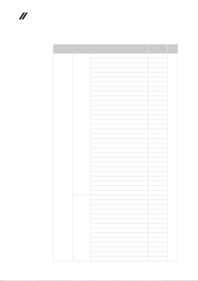
Lenovo Flex 2-14/Flex 2-14D/Flex 2-15/Flex 2-15D Hardware Maintenance Manual
Keyboard
Table 7. Parts list—Keyboard
Language P/N CRU
Indian 25214539 **
Czechoslovakian 25214537
Bulgarian 25214538
International English 25214536
Swiss 25214535
Slovenian 25214534
Icelandic 25214533
Belgian 25214532
Four Nordic countries 25214531
Hungarian 25214530
Hebrew 25214529
Greek 25214528
Dutch 25214527
Japanese 25214526
Chicony
(black)
keyboard
Flex 2-14/
Flex 2-14D
Normal
(Black)
Sunrex
( Black)
Brazilian 25214525
Arabic 25214524
German 25214523
French 25214522
Russian 25214521
Traditional Chinese 25214520
Korean 25214519
Canadian English&French 25214518
Latin 25214517
Portuguese 25214516
Thai 25214515
Turkish 25214514
Spanish 25214513
Italian 25214512
U.K. English 25214511
English 25214510
Indian 25214569
Czechoslovakian 25214567
Bulgarian 25214568
International English 25214566
Swiss 25214565
Slovenian 25214564
Icelandic 25214563
Belgian 25214562
Four Nordic countries 25214561
Hungarian 25214560
Hebrew 25214559
Greek 25214558
Dutch 25214557
Brazilian 25214555
ID
88
Page 93

Lenovo Flex 2-14/Flex 2-14D/Flex 2-15/Flex 2-15D
Table 7. Parts list—Keyboard (continued)
Language P/N CRU
Arabic 25214554 **
German 25214553
French 25214552
Russian 25214551
Traditional Chinese 25214550
Korean 25214549
Sunrex
( Black)
(continued)
keyboard
Flex2-14/
Flex 2-14D
Normal
(Black)
(continued)
Liteon
(Black)
Canadian English&French 25214548
Latin 25214547
Portuguese 25214546
Thai 25214545
Turkish 25214544
Spanish 25214543
Italian 25214542
U.K. English 25214541
English 25214540
Indian 25215219
Bulgarian 25215218
Czechoslovakian 25215217
International English 25215216
Swiss 25215215
Slovenian 25215214
Icelandic 25215213
Belgian 25215212
Four Nordic countries 25215211
Hungarian 25215210
Hebrew 25215209
Greek 25215208
Dutch 25215207
Japanese 25215206
Brazilian 25215205
Arabic 25215204
German 25215203
French 25215202
Russian 25215201
Traditional Chinese 25215200
Korean 25215199
Canadian English&French 25215198
Latin 25215197
Portuguese 25215196
Thai 25215195
Turkish 25215194
Spanish 25215193
Italian 25215192
U.K. English 25215191
English 25215190
ID
89
Page 94
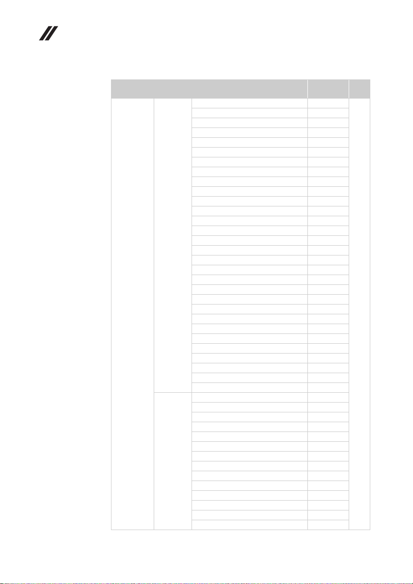
Lenovo Flex 2-14/Flex 2-14D/Flex 2-15/Flex 2-15D Hardware Maintenance Manual
Table 7. Parts list—Keyboard (continued)
Language P/N CRU
Indian 25215129 **
Bulgarian 25215128
Czechoslovakian 25215127
International English 25215126
Swiss 25215125
Slovenian 25215124
Icelandic 25215123
Belgian 25215122
Four Nordic countries 25215121
Hungarian 25215120
Hebrew 25215119
Greek 25215118
Dutch 25215117
Japanese 25215116
Chicony
( Silver)
keyboard
Flex 2-14/
Flex 2-14D
Normal
(Silver)
Sunrex
(Silver)
Brazilian 25215115
Arabic 25215114
German 25215113
French 25215112
Russian 25215111
Traditional Chinese 25215110
Korean 25215109
Canadian English&French 25215108
Latin 25215107
Portuguese 25215106
Thai 25215105
Turkish 25215104
Spanish 25215103
Italian 25215102
U.K. English 25215101
English 25215100
Indian 25215159
Bulgarian 25215158
Czechoslovakian 25215157
International English 25215156
Swiss 25215155
Slovenian 25215154
Icelandic 25215153
Belgian 25215152
Four Nordic countries 25215151
Hungarian 25215150
Hebrew 25215149
Greek 25215148
Dutch 25215147
Brazilian 25215145
ID
90
Page 95

Lenovo Flex 2-14/Flex 2-14D/Flex 2-15/Flex 2-15D
Table 7. Parts list—Keyboard (continued)
Language P/N CRU
Arabic 25215144 **
German 25215143
French 25215142
Russian 25215141
Traditional Chinese 25215140
Korean 25215139
Sunrex
(Silver)
(continued)
keyboard
Flex 2-14/
Flex 2-14D
Normal
(Silver)
(continued)
Liteon
(Silver)
Canadian English&French 25215138
Latin 25215137
Portuguese 25215136
Thai 25215135
Turkish 25215134
Spanish 25215133
Italian 25215132
U.K. English 25215131
English 25215130
Indian 25215189
Bulgarian 25215188
Czechoslovakian 25215187
International English 25215186
Swiss 25215185
Slovenian 25215184
Icelandic 25215183
Belgian 25215182
Four Nordic countries 25215181
Hungarian 25215180
Hebrew 25215179
Greek 25215178
Dutch 25215177
Japanese 25215176
Brazilian 25215175
Arabic 25215174
German 25215173
French 25215172
Russian 25215171
Traditional Chinese 25215170
Korean 25215169
Canadian English&French 25215168
Latin 25215167
Portuguese 25215166
Thai 25215165
Turkish 25215164
Spanish 25215163
Italian 25215162
U.K. English 25215161
English 25215160
ID
91
Page 96
Lenovo Flex 2-14/Flex 2-14D/Flex 2-15/Flex 2-15D Hardware Maintenance Manual
Table 7. Parts list—Keyboard (continued)
Language P/N CRU
English 25215587 **
English (USA) 25215588
U.K. English 25215589
Italian 25215590
Spanish 25215591
Turkish 25215592
Thai 25215593
Portuguese 25215594
Latin 25215595
Canadian English&French 25215596
Korean 25215597
Traditional Chinese 25215598
Russian 25215599
French 25215600
Chicony
Silver
keyboard
Flex 2-14
Backlight
(Silver)
Liteon
Silver
German 25215601
Arabic 25215602
Brazilian 25215603
Japanese 25215604
Dutch 25215605
Greek 25215606
Hebrew 25215607
Hungarian 25215608
Four Nordic countries 25215609
Belgian 25215610
Icelandic 25215611
Slovenian 25215612
Swiss 25215613
International English 25215614
Czechoslovakian 25215615
Bulgarian 25215616
Indian 25215617
English 25215618
English (USA) 25215619
U.K. English 25215620
Italian 25215621
Spanish 25215622
Turkish 25215623
Thai 25215624
Portuguese 25215625
Latin 25215626
Canadian English&French 25215627
Korean 25215628
Traditional Chinese 25215629
Russian 25215630
French 25215631
German 25215632
ID
92
Page 97
Lenovo Flex 2-14/Flex 2-14D/Flex 2-15/Flex 2-15D
Table 7. Parts list—Keyboard (continued)
Language P/N CRU
Arabic 25215633 **
Brazilian 25215634
Japanese 25215635
Dutch 25215636
Greek 25215637
Hebrew 25215638
keyboard
Flex 2-14
Backlight
(Silver)
keyboard
Flex 2-14
Backlight
(Black)
Liteon
Silver
(continued)
Chicony
Black
Hungarian 25215639
Four Nordic countries 25215640
Belgian 25215641
Icelandic 25215642
Slovenian 25215643
Swiss 25215644
International English 25215645
Czechoslovakian 25215646
Bulgarian 25215647
Indian 25215648
English 25214816
English (USA) 25214817
U.K. English 25214818
Italian 25214819
Spanish 25214820
Turkish 25214821
Thai 25214822
Portuguese 25214823
Latin 25214824
Canadian English&French 25214825
Korean 25214826
Traditional Chinese 25214827
Russian 25214828
French 25214829
German 25214830
Arabic 25214831
Brazilian 25214832
Japanese 25214833
Dutch 25214834
Greek 25214835
Hebrew 25214836
Hungarian 25214837
Four Nordic countries 25214838
Belgian 25214839
Icelandic 25214840
Slovenian 25214841
Swiss 25214842
International English 25214843
Czechoslovakian 25214844
Bulgarian 25214845
Indian 25214846
ID
93
Page 98

Lenovo Flex 2-14/Flex 2-14D/Flex 2-15/Flex 2-15D Hardware Maintenance Manual
Table 7. Parts list—Keyboard (continued)
Language P/N CRU
English 25215649 **
English(USA) 25215650
U.K. English 25215651
Italian 25215652
Spanish 25215653
Turkish 25215654
Thai 25215655
Portuguese 25215656
Latin 25215657
Canadian English&French 25215658
Korean 25215659
Traditional Chinese 25215660
Russian 25215661
keyboard
Flex 2-14
Backlight
(Black)
(continued)
Liteon
Black
French 25215662
German 25215663
Arabic 25215664
Brazilian 25215665
Japanese 25215666
Dutch 25215667
Greek 25215668
Hebrew 25215669
Hungarian 25215670
Four Nordic countries 25215671
Belgian 25215672
Icelandic 25215673
Slovenian 25215674
Swiss 25215675
International English 25215676
Czechoslovakian 25215677
Bulgarian 25215678
Indian 25215679
ID
94
Page 99

Lenovo Flex 2-14/Flex 2-14D/Flex 2-15/Flex 2-15D
Table 7. Parts list—Keyboard (continued)
Language P/N CRU
English 25214725 **
U.K. English 25214726
Italian 25214727
Spanish 25214728
Turkish 25214729
Thai 25214730
Portuguese 25214731
Latin 25214732
Canadian English&French 25214733
Korean 25214734
Traditional Chinese 25214735
Russian 25214736
French 25214737
Chicony
Black
keyboard
Flex2-15/
Flex 2-15D
Normal
(Black)
Sunrex
Black
German 25214738
Arabic 25214739
Brazilian 25214740
Dutch 25214742
Greek 25214743
Hebrew 25214744
Hungarian 25214745
Four Nordic countries 25214746
Belgian 25214747
Icelandic 25214748
Slovenian 25214749
Swiss 25214750
International English 25214751
Czechoslovakian 25214752
Bulgarian 25214753
Indian 25214754
English 25214755
U.K. English 25214756
Italian 25214757
Spanish 25214758
Turkish 25214759
Thai 25214760
Portuguese 25214761
Latin 25214762
Canadian English&French 25214763
Korean 25214764
Traditional Chinese 25214765
Russian 25214766
French 25214767
German 25214768
ID
95
Page 100
Lenovo Flex 2-14/Flex 2-14D/Flex 2-15/Flex 2-15D Hardware Maintenance Manual
Table 7. Parts list—Keyboard (continued)
Language P/N CRU
Arabic 25214769 **
Brazilian 25214770
Japanese 25214771
Dutch 25214772
Greek 25214773
Hebrew 25214774
Sunrex
Black
(continued)
keyboard
Flex2-15/
Flex 2-15D
Normal
(Black)
(continued)
Darfon
Black
Hungarian 25214775
Four Nordic countries 25214776
Belgian 25214777
Icelandic 25214778
Slovenian 25214779
Swiss 25214780
International English 25214781
Czechoslovakian 25214782
Bulgarian 25214783
Indian 25214784
English 25214785
U.K. English 25214786
Italian 25214787
Spanish 25214788
Turkish 25214789
Thai 25214790
Portuguese 25214791
Latin 25214792
Canadian English&French 25214793
Korean 25214794
Traditional Chinese 25214795
Russian 25214796
French 25214797
German 25214798
Arabic 25214799
Brazilian 25214800
Japanese 25214801
Dutch 25214802
Greek 25214803
Hebrew 25214804
Hungarian 25214805
Four Nordic countries 25214806
Belgian 25214807
Icelandic 25214808
Slovenian 25214809
Swiss 25214810
International English 25214811
Czechoslovakian 25214812
Bulgarian 25214813
Indian 25214814
ID
96
 Loading...