


1
Lenovo A536
Service Manual
LENOVO

2
Content
1. How to assemble and disassemble LENOVO A536 ................................................................. 3
1.1 The phone disassemble guide ........................................................................................ 3
1.2 The phone assemble guide ............................................................................................ 9
2. Main board and Sub FPC layout introduction ......................................................................... 10
2.1 Main board top view ...................................................................................................... 10
2.2 Main board bottom view ............................................................................................... 11
3. Troubleshooting Procedure ..................................................................................................... 12
3.1 No boot ......................................................................................................................... 12
3.2 Touch panel have no effect ........................................................................................... 13
3.3 Charging anomaly ......................................................................................................... 14
3.4 Calling receiver sound has poor quality ....................................................................... 16
3.5 Speaker has no sound .................................................................................................. 17
3.6 LCD has no display ....................................................................................................... 18
3.7 Phone crash .................................................................................................................. 20
3.8 Key has no effect .......................................................................................................... 21
3.9 Communication signal abnormality .............................................................................. 22
3.10 Calling receiver has no sound ...................................................................................... 23
3.11 Microphone has no effect ............................................................................................. 24
3.12 Display color distortion.................................................................................................. 25
3.13 Speaker tone distortion ................................................................................................. 26
3.14 Speaker tone smaller .................................................................................................... 27
3.15 No charging................................................................................................................... 28
3.16 Camera has no effect ................................................................................................... 29
3.17 Auto shutdown .............................................................................................................. 31
3.18 SIM Card has not be detected ...................................................................................... 32
3
1. How to assemble and disassemble
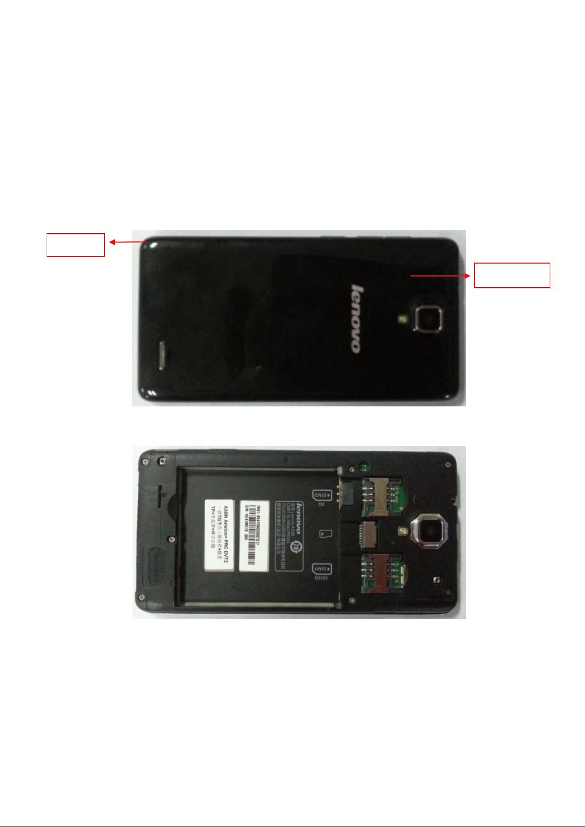
Battery cover
Buckle
LENOVO A536
1.1 The phone disassemble guide
1) Remove battery cover
Remove battery cover from B cover at the buckle, shown as picture (1) and (2).
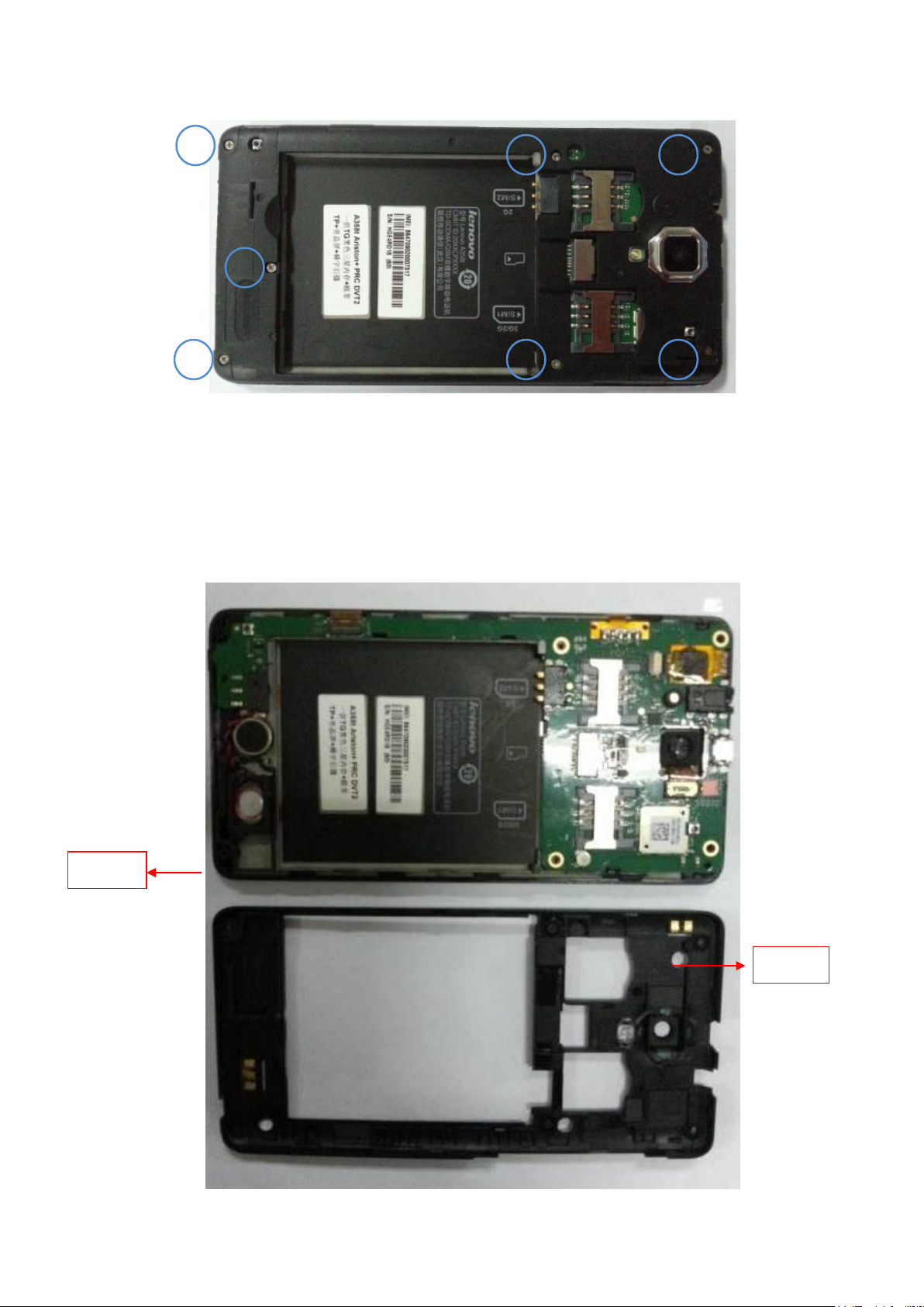
2) Remove screws
Remove the 7 screws as shown below. Use cross head driver to remove the screws.
(1)
(2)
4
Screw length to 1 & 2 & 3 & 4 positions are S1.6×L4.1×D2.6×T0.5
1
2
5
6
7
3
4
Buckle
B cover
Screw length to 4 & 5 & 6 positions are M1.4X2.8
3) Remove B cover
Separate B cover from A cover at the buckle, then unclench B cover and A cover with a
plectrum alongside the shell gap.
5
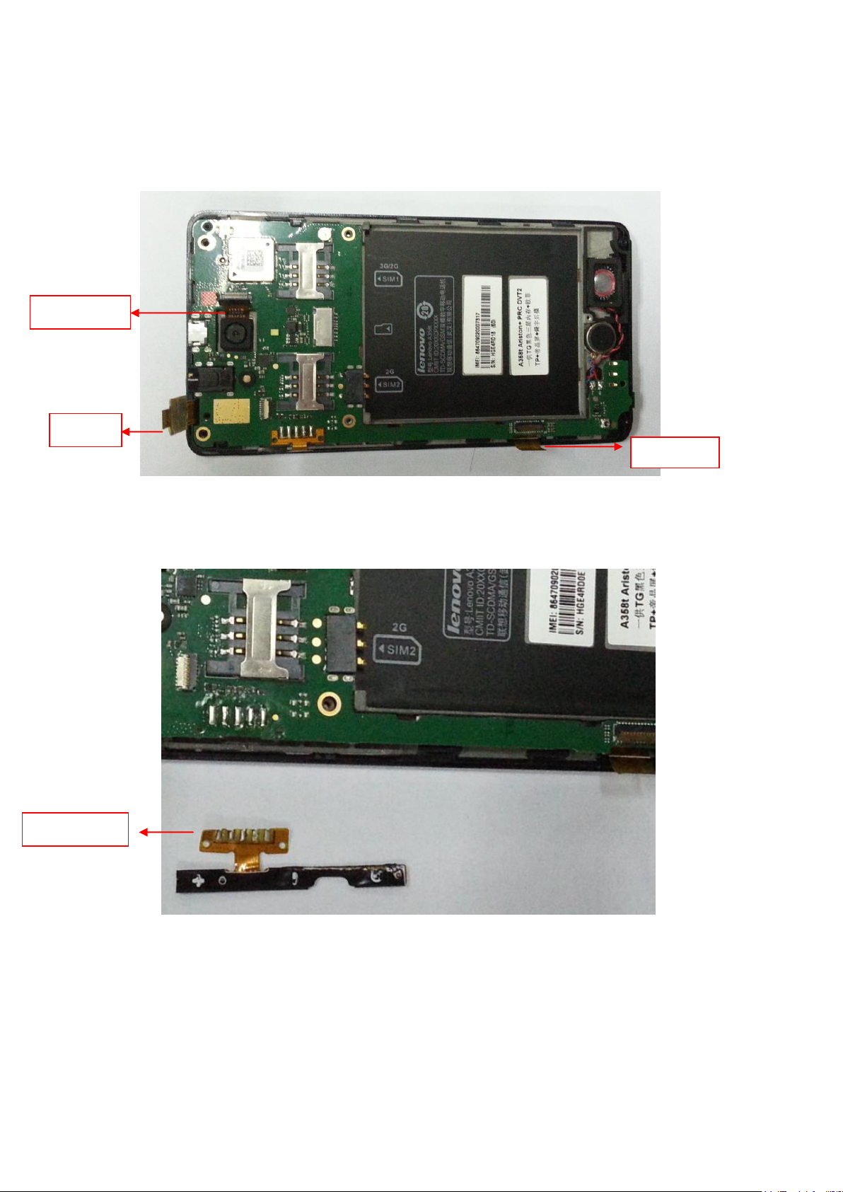
Side key FPC
LCD FPC
TP FPC
Camera FPC
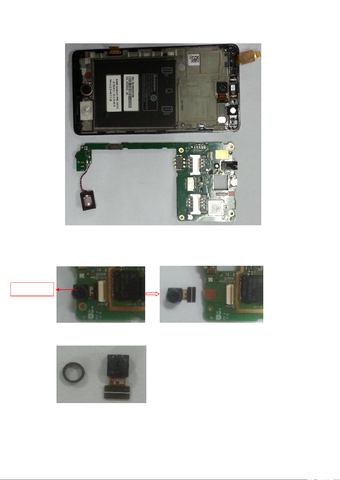
4) Disassemble PCBA
Open the FPC connector of TP, LCD and Camera, and extract all the FPCs.
TP FPC is glued to the main board
Pull off side key FPC from A cover, and remove it from main board with a soldering iron.
Side key FPC is glued to the A cover.
Remove the foam on the main board.
6
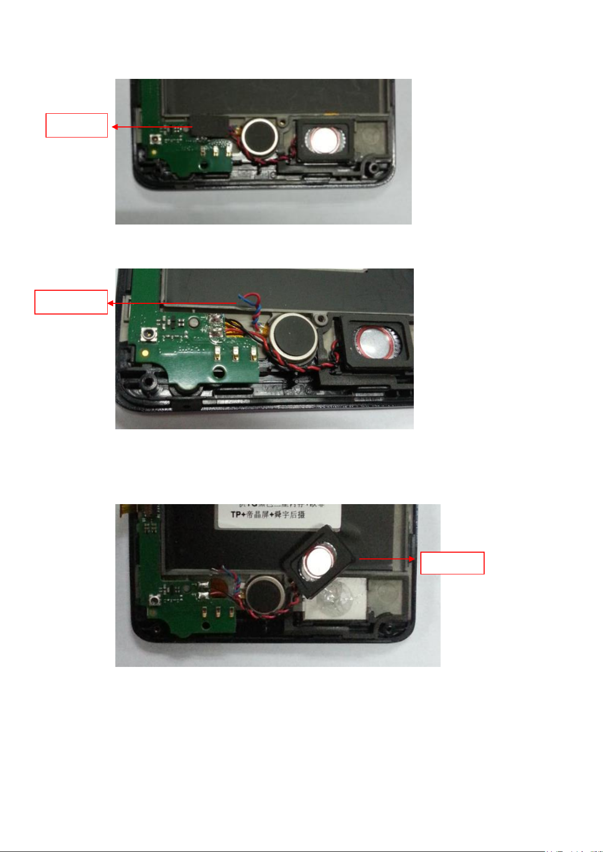
Foam
Vibrator wire
Speaker
Remove the vibrator wire from the main board with a soldering iron.
Remove the speaker from A cover. The speaker is glued on the A cover, need to pry up
with tweezers.
The speaker adhesive comes along with the speaker.
Remove the main board from A cover.
7
Front camera
5) Remove front camera and MIC rubber
Open the front camera FPC connector and extract the FPC.
The camera adhesive comes along with the front camera.
Remove the front camera foam.
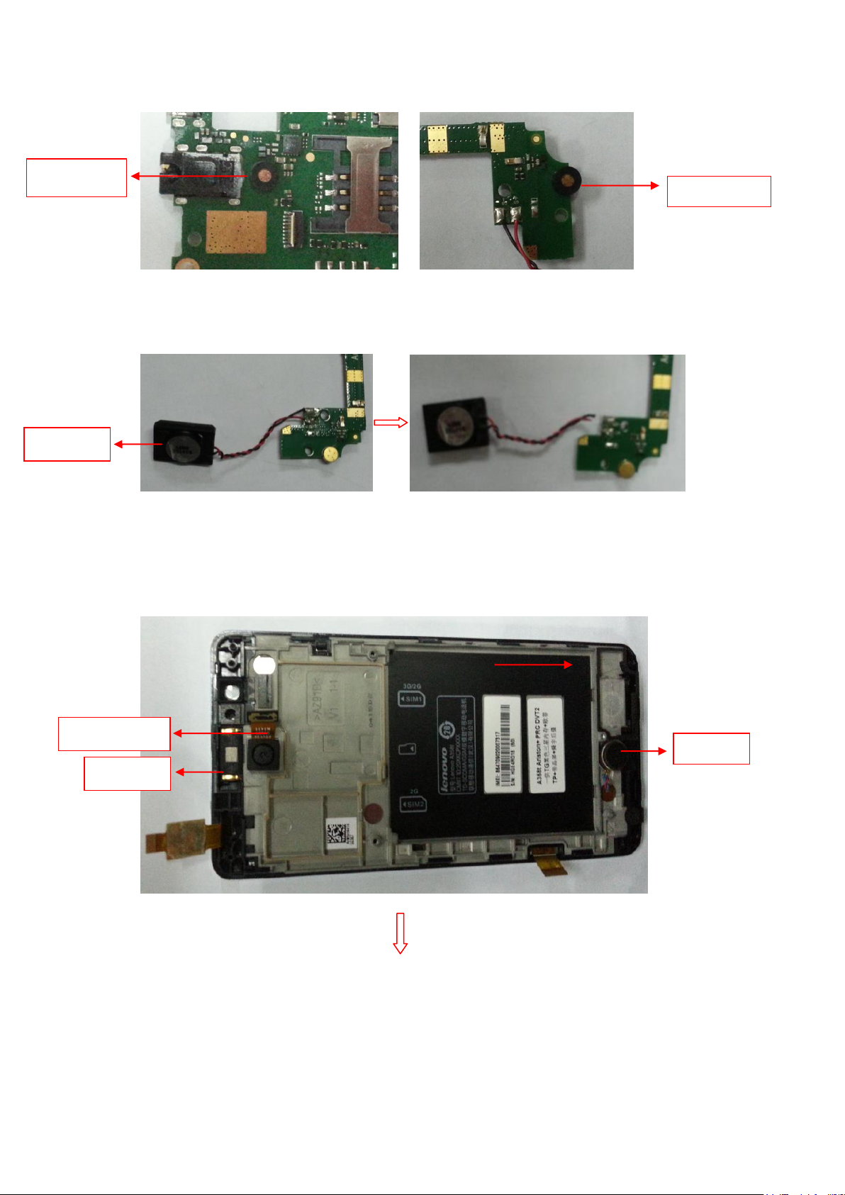
Remove two MIC rubbers on the main board. Positions of MIC rubbers are shown below.
8
MIC rubber
MIC rubber
Speaker
Main camera
Receiver
Vibrator
6) Remove speaker
Remove speaker from the main board with a soldering iron.
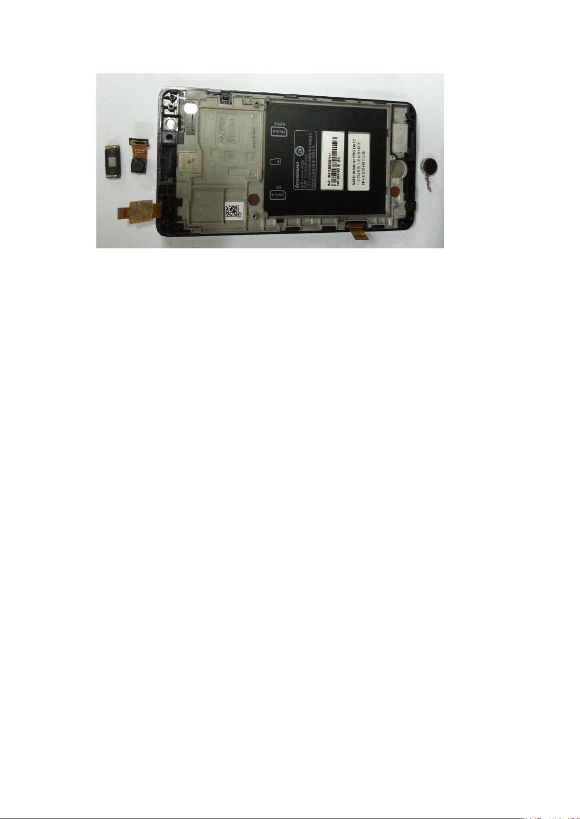
7) Remove main camera, receiver and vibrator from A cover.
Main camera, receiver and vibrator are glued to the A cover.
The adhesives come along with main camera, receiver and vibrator.
9
1.2 The phone assemble guide
Assemble and disassemble process is opposite
10
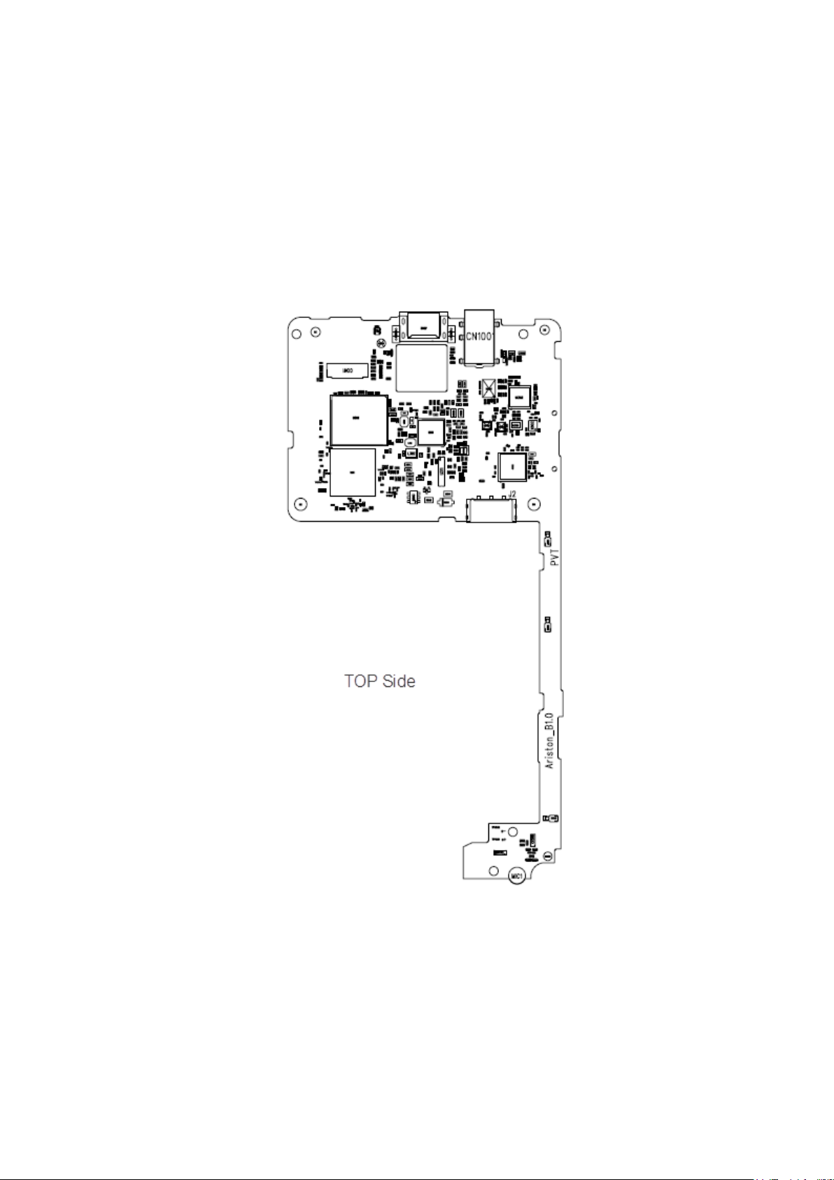
2. Main board and Sub FPC layout introduction
2.1 Main board top view
 Loading...