Lenovo 1008, 1010, 992, 981 User Manual
ThinkServer
Hardware Maintenance Manual
ThinkServer TS200v Types 0981, 0992, 1008, and 1010

ThinkServer
Hardware Maintenance Manual
ThinkServer TS200v Types 0981, 0992, 1008, and 1010
Before using this information and the product it supports, be sure to read and understand the Safety Information book and Appendix A “Notices” on page 87.
Second Edition (December 2010)
© Copyright Lenovo 2010, .
LENOVO products, data, computer software, and services have been developed exclusively at private expense and are sold to governmental entities as commercial items as defined by 48 C.F.R. 2.101 with limited and restricted rights to use, reproduction and disclosure.
LIMITED AND RESTRICTED RIGHTS NOTICE: If products, data, computer software, or services are delivered pursuant a General Services Administration ²GSA² contract, use, reproduction, or disclosure is subject to restrictions set forth in Contract No. GS-35F-05925.

Contents
Chapter 1. About this manual . . . . . |
1 |
Important Safety Information . . . . . . . . . . |
1 |
Safety statements . . . . . . . . . . . . . . |
2 |
Important information about replacing RoHS |
|
compliant FRUs . . . . . . . . . . . . . . . |
5 |
Chapter 2. General information. . . . . |
7 |
Features and specifications. . . . . . . . . . . |
7 |
Software . . . . . . . . . . . . . . . . . . |
9 |
EasyStartup . . . . . . . . . . . . . . . |
9 |
EasyManage. . . . . . . . . . . . . . . |
9 |
Chapter 3. General Checkout. . . . . |
11 |
Problem determination tips . . . . . . . . . . |
11 |
Chapter 4. Diagnostics . . . . . . . . |
13 |
PC-Doctor for DOS . . . . . . . . . . . . . |
13 |
Creating a diagnostic disc . . . . . . . . |
13 |
Running the diagnostic program from a |
|
diagnostic disc . . . . . . . . . . . . . |
13 |
Navigating through the diagnostics |
|
programs . . . . . . . . . . . . . . . |
13 |
Running tests . . . . . . . . . . . . . |
14 |
Viewing the test log . . . . . . . . . . . |
15 |
Troubleshooting tables . . . . . . . . . . . |
15 |
Hard disk drive boot error . . . . . . . . |
15 |
Power Supply Problems . . . . . . . . . |
16 |
Beep symptoms . . . . . . . . . . . . |
16 |
POST error codes. . . . . . . . . . . . |
17 |
EasyStartup problems . . . . . . . . . . |
18 |
Miscellaneous error messages . . . . . . |
19 |
Undetermined problems . . . . . . . . . |
21 |
Chapter 5. Locating Server Controls |
|
and connectors . . . . . . . . . . . . |
23 |
Front view . . . . . . . . . . . . . . . . |
23 |
Rear view. . . . . . . . . . . . . . . . . |
23 |
System-board internal connectors . . . . . . . |
25 |
Internal components . . . . . . . . . . . . |
26 |
Chapter 6. Replacing FRUs. . . . . . |
27 |
Guidelines for trained service technicians . . . . |
27 |
Inspecting for unsafe conditions . . . . . . |
27 |
Guidelines for servicing electrical equipment . |
28 |
Handling static-sensitive devices . . . . . . . |
28 |
Server components . . . . . . . . . . . . . |
29 |
Replacing FRUs . . . . . . . . . . . . . . |
30 |
Removing the server cover . . . . . . . . |
30 |
Removing and reinstalling the front bezel . . |
31 |
Installing or replacing a PCI card . . . . . . |
32 |
Replacing the battery . . . . . . . . . . |
35 |
Installing or replacing a memory module . . . |
36 |
Installing or replacing the optical drive . . . |
38 |
Replacing the secondary hard disk drive. . . |
40 |
Replacing the power supply assembly . . . |
43 |
Replacing the heat sink and fan assembly . . |
44 |
Replacing the microprocessor . . . . . . . |
45 |
Replacing the system board . . . . . . . |
47 |
Replacing the primary hard disk drive . . . . |
50 |
Replacing the front fan assembly . . . . . |
53 |
Replacing the rear fan assembly . . . . . . |
55 |
Completing the parts replacement . . . . . |
57 |
Updating the server configuration . . . . . |
58 |
Chapter 7. Parts Listing, TS200v |
|
Machine Types 0981, 0992, 1008, and |
|
1010 . . . . . . . . . . . . . . . . . . |
59 |
Machine Type 0981 . . . . . . . . . . . . . |
59 |
Machine Type 0992 . . . . . . . . . . . . . |
64 |
Machine Type 1008 . . . . . . . . . . . . . |
68 |
Machine Type 1010 . . . . . . . . . . . . . |
72 |
Chapter 8. Configuring the server . . |
77 |
Using the Setup Utility program . . . . . . . . |
77 |
Starting the Setup Utility program . . . . . |
77 |
Viewing and changing settings . . . . . . |
77 |
Using passwords . . . . . . . . . . . . |
78 |
Enabling or disabling a device . . . . . . . |
79 |
Selecting a startup device . . . . . . . . |
79 |
Advanced settings . . . . . . . . . . . |
80 |
Exiting from the Setup Utility program . . . |
80 |
Configuring RAID. . . . . . . . . . . . . . |
80 |
RAID Level . . . . . . . . . . . . . . |
80 |
Configuring the system UEFI to enable SATA |
|
RAID functionality. . . . . . . . . . . . |
81 |
Creating RAID volumes . . . . . . . . . |
81 |
Deleting RAID volumes . . . . . . . . . |
81 |
Updating system programs. . . . . . . . . . |
82 |
Using system programs . . . . . . . . . |
82 |
Updating (flashing) the UEFI from a disc . . . |
82 |
Updating (flashing) the UEFI from your |
|
operating system . . . . . . . . . . . . |
83 |
Recovering from a POST/UEFI update |
|
failure . . . . . . . . . . . . . . . . |
83 |
Using the ThinkServer EasyStartup program . . . |
84 |
© Copyright Lenovo 2010, |
iii |
Installing ThinkServer EasyManage Agent . . . . 85
Appendix A. Notices . . . . . . . . . |
87 |
Export classification notice . . . . . . . . . . |
88 |
Television output notice . . . . . . . . . . . |
88 |
European conformance CE mark . . . . . . . |
88 |
Trademarks . . . . . . . . . . . . . . . . |
88 |
Electronic emissions notices . . . . . . . . . |
88 |
Federal Communications Commission |
|
Declaration of Conformity . . . . . . . . |
88 |
Industry Canada Class B emission compliance |
|
statement . . . . . . . . . . . . . . . |
89 |
European Union EMC Directive conformance |
|
statement . . . . . . . . . . . . . . . |
89 |
EU-EMC Directive (2004/108/EC) EN 55022 |
|
class B Statement of Compliance . . . . . |
89 |
Japanese VCCI Class B statement . . . . . |
90 |
Japanese compliance for products less than |
|
or equal to 20 A per phase . . . . . . . . |
90 |
Federal Communications Commission (FCC) and |
|
telephone company requirements . . . . . . . |
90 |
Canadian Department of Communications |
|
certification label . . . . . . . . . . . . . . |
91 |
Power cord notice . . . . . . . . . . . . . |
91 |
Polyvinyl Chloride (PVC) cable and cord notice . . |
93 |
Turkish statement of compliance . . . . . . . |
93 |
Waste electrical and electronic equipment (WEEE) |
|
notices. . . . . . . . . . . . . . . . . . |
93 |
European Union (EU) WEEE statement . . . |
94 |
Japanese recycling statement. . . . . . . . . |
94 |
Collecting and recycling a disused Lenovo |
|
computer or monitor . . . . . . . . . . |
94 |
Disposing of Lenovo computer components . |
94 |
Disposing of disused lithium batteries from |
|
Lenovo computers . . . . . . . . . . . |
94 |
Index. . . . . . . . . . . . . . . . . . |
97 |
iv ThinkServerHardware Maintenance Manual
Chapter 1. About this manual
This Hardware Maintenance Manual contains information to help you solve problems that might occur in your server. It describes the diagnostic tools that come with the server, error codes and suggested actions, and instructions for replacing failing components.
Replaceable components are of three types:
•Self-service customer replaceable unit (CRU): Replacement of self-service CRUs is your responsibility. If Lenovo® installs a self-service CRU at your request, you will be charged for the installation.
•Optional-service customer replaceable unit: You may install an optional-service CRU yourself or request Lenovo to install it, at no additional charge, under the type of warranty service that is designated for the server.
•Field replaceable unit (FRU): FRUs must be installed only by trained service technicians.
The most recent version of this document is available at http://www.lenovo.com/support.
Before servicing a Lenovo product, be sure to read the Safety Information. See “Important Safety Information” on page 1.
For information about the terms of the warranty and getting service and assistance, see the Warranty and Support Information document.
Important Safety Information
Be sure to read all caution and danger statements in this book before performing any of the instructions.
Veuillez lire toutes les consignes de type DANGER et ATTENTION du présent document avant d'exécuter les instructions.
Lesen Sie unbedingt alle Hinweise vom Typ "ACHTUNG" oder "VORSICHT" in dieser Dokumentation, bevor Sie irgendwelche Vorgänge durchführen
Leggere le istruzioni introdotte da ATTENZIONE e PERICOLO presenti nel manuale prima di eseguire una qualsiasi delle istruzioni
Certifique-se de ler todas as instruções de cuidado e perigo neste manual antes de executar qualquer uma das instruções
Es importante que lea todas las declaraciones de precaución y de peligro de este manual antes de seguir las instrucciones.
© Copyright Lenovo 2010, |
1 |
Safety statements
Important: Each caution and danger statement in this document is labeled with a number. This number is used to cross reference an English-language caution or danger statement with translated versions of the caution or danger statement in the Safety Information document.
For example, if a caution statement is labeled "Statement 1," translations for that caution statement are in the Safety Information document under "Statement 1."
Be sure to read all caution and danger statements in this document before you perform the procedures. Read any additional safety information that comes with the server or optional device before you install the device.
Attention: Use No. 26 AWG or larger UL-listed or CSA certified telecommunication line cord.
Statement 1
 DANGER
Electrical current from power, telephone, and communication cables is hazardous. To avoid a shock hazard:
•Do not connect or disconnect any cables or perform installation, maintenance, or reconfiguration of this product during an electrical storm.
•Connect all power cords to a properly wired and grounded electrical outlet.
•Connect to properly wired outlets any equipment that will be attached to this product.
•When possible, use one hand only to connect or disconnect signal cables.
•Never turn on any equipment when there is evidence of fire, water, or structural damage.
•Disconnect the attached power cords, telecommunications systems, networks, and modems before you open the device covers, unless instructed otherwise in the installation and configuration procedures.
•Connect and disconnect cables as described in the following table when installing, moving, or opening covers on this product or attached devices.
To Connect: |
To Disconnect: |
||
1. |
Turn everything OFF. |
1. |
Turn everything OFF. |
2. |
First, attach all cables to devices. |
2. |
First, remove power cords from outlet. |
3. |
Attach signal cables to connectors. |
3. |
Remove signal cables from connectors. |
4. |
Attach power cords to outlet. |
4. |
Remove all cables from devices. |
5. |
Turn device ON. |
|
|
|
|
|
|
Statement 2
2 ThinkServerHardware Maintenance Manual

CAUTION:
When replacing the lithium battery, use only a type battery recommended by the manufacturer. If your system has a module containing a lithium battery, replace it only with the same module type made by the same manufacturer. The battery contains lithium and can explode if not properly used, handled, or disposed of. Do not:
•Throw or immerse into water
•Heat to more than 100°C (212°F)
•Repair or disassemble
Dispose of the battery as required by local ordinances or regulations.
Statement 3
CAUTION:
When laser products (such as CD-ROMs, DVD drives, fiber optic devices, or transmitters) are installed, note the following:
•Do not remove the covers. Removing the covers of the laser product could result in exposure to hazardous laser radiation. There are no serviceable parts inside the device.
•Use of controls or adjustments or performance of procedures other than those specified herein might result in hazardous radiation exposure.
 DANGER
Some laser products contain an embedded Class 3A or Class 3B laser diode. Note the following.
Laser radiation when open. Do not stare into the beam, do not view directly with optical instruments, and avoid direct exposure to the beam.
Class 1 Laser Product
Laser Klasse 1
Laser Klass 1
Luokan 1 Laserlaite
`
Appareil A Laser de Classe 1
Statement 4
Chapter 1. About this manual 3
≥ 18 kg (39.7 lb) |
≥ 32 kg (70.5 lb) |
≥ 55 kg (121.2 lb) |
CAUTION:
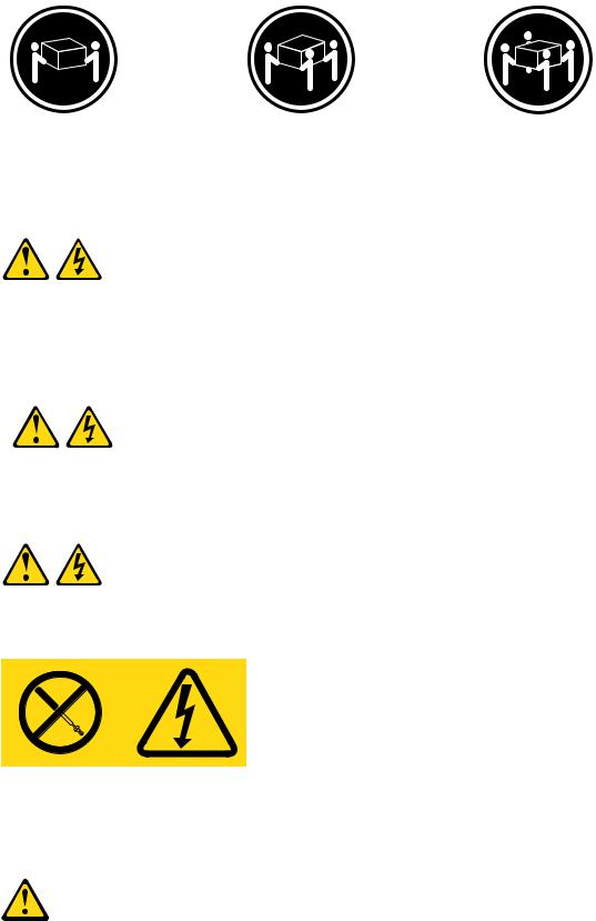
Use safe practices when lifting.
Statement 5
CAUTION:
The power control button on the device and the power switch on the power supply do not turn off the electrical current supplied to the device. The device also might have more than one power cord. To remove all electrical current from the device, ensure that all power cords are disconnected from the power source.
2 


 1
1 


Statement 8
CAUTION:
Never remove the cover on a power supply or any part that has the following label attached.
Hazardous voltage, current, and energy levels are present inside any component that has this label attached. There are no serviceable parts inside these components. If you suspect a problem with one of these parts, contact a service technician.
Statement 26
CAUTION:
Do not place any object on top of rack-mounted devices.
4 ThinkServerHardware Maintenance Manual
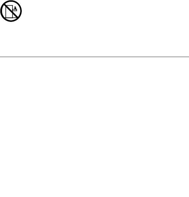
Attention: This server is suitable for use on an IT power distribution system whose maximum phase-to-phase voltage is 240 V under any distribution fault condition.
Important: This product is not suitable for use with visual display workplace devices according to Clause 2 of the German Ordinance for Work with Visual Display Units.
Important information about replacing RoHS compliant FRUs
RoHS, The Restriction of Hazardous Substances in Electrical and Electronic Equipment Directive (2002/95/EC) is a European Union legal requirement affecting the global electronics industry. RoHS requirements must be implemented on Lenovo products placed on the market and sold in the European Union after June 2006. Products on the market before June 2006 are not required to have RoHS compliant parts. If the parts are not compliant originally, replacement parts can also be noncompliant, but in all cases, if the parts are compliant, the replacement parts must also be compliant.
Note: RoHS and non-RoHS FRU part numbers with the same fit and function are identified with unique FRU part numbers.
Lenovo plans to transition to RoHS compliance well before the implementation date and expects its suppliers to be ready to support Lenovo's requirements and schedule in the EU. Products sold in 2005 will contain some RoHS compliant FRUs. The following statement pertains to these products and any product Lenovo produces containing RoHS compliant parts.
RoHS compliant ThinkServer TS200v parts have unique FRU part numbers. Before or after June 2006, failed RoHS compliant parts must always be replaced using RoHS compliant FRUs, so only the FRUs identified as compliant in the system hardware maintenance manual or direct substitutions for those FRUs can be used.
Products marketed before June 2006 |
Products marketed after June 2006 |
||
|
|
|
|
Current or original part |
Replacement FRU |
Current or original part |
Replacement FRU |
|
|
|
|
Non-RoHS |
Can be Non-RoHS |
Must be RoHS |
Must be RoHS |
|
|
|
|
Non-RoHS |
Can be RoHS |
|
|
|
|
|
|
Non-RoHS |
Can sub to RoHS |
|
|
|
|
|
|
RoHS |
Must be RoHS |
|
|
|
|
|
|
Note: A direct substitution is a part with a different FRU part number that is automatically shipped by the distribution center at the time of order.
Chapter 1. About this manual 5
6 ThinkServerHardware Maintenance Manual

Chapter 2. General information
This chapter provides general information that applies to all machine types supported by this publication.
Features and specifications
The following information is a summary of the features and specifications of the server. Depending on the server model, some features might not be available, or some specifications might not apply.
© Copyright Lenovo 2010, |
7 |
Table 1. Features and specifications
MicroprocessorYour server |
Expansion |
Security features |
||||
comes with one of the following |
• |
Two hard disk drive bays (one |
• |
Computrace |
||
microprocessors (internal cache size |
||||||
|
standard and one optional) |
• Enabling or disabling a device |
||||
varies by model type): |
|
|||||
• Two optical drive bays |
||||||
• |
Intel® Celeron® microprocessor |
• |
Enabling or disabling USB |
|||
• |
Two PCI card slots |
|||||
• Intel Core™ i3 microprocessor |
|
connectors individually |
||||
• |
One PCI Express x1 card slot |
• Hard disk drive password |
||||
• Intel Core i5 microprocessor |
||||||
• |
One PCI Express x16 card slot |
• |
Power-On Password (POP) and |
|||
• |
Intel Pentium® microprocessor |
|||||
System management features |
|
Administrator Password for UEFI |
||||
|
|
|
||||
• Use the Setup Utility program to |
|
access |
||||
• |
Ability to store power-on self-test |
|
||||
|
determine the type and speed of |
• |
Startup sequence control |
|||
|
the microprocessor. |
|
(POST) hardware test results |
|||
|
|
• Startup without keyboard or mouse |
||||
• |
For a list of supported |
• |
Automatic power-on startup |
|||
• Support for an integrated cable |
||||||
|
microprocessors, see |
• |
Intel Active Management |
|||
|
|
lock (Kensington lock) |
||||
|
http://www.lenovo.com/thinkserver |
|
||||
|
|
Technology (AMT) |
|
|||
|
|
|
|
|||
|
and click the Options tab. |
|
• Support for a padlock |
|||
|
• Intel Hyper-Threading technology |
|||||
Memory |
• Trusted Platform Module (TPM) |
|||||
|
(some models) |
|||||
• |
Supports up to four DDR3 ECC |
• |
Intel Rapid Storage Technology |
Preinstalled operating systemSome |
||
|
UDIMMs (double data rate 3 error |
|
(RST) |
models are preinstalled with one of |
||
|
correction code unbuffered dual |
• |
Preboot Execution Environment |
the following operating systems: |
||
|
inline memory modules) |
|
|
|||
|
|
(PXE) |
• |
Microsoft® Windows Server® |
||
|
|
|
||||
Internal drives |
• |
System Management (SM) UEFI |
|
2008 R2 Foundation |
||
|
|
|
|
|||
• |
Serial Advanced Technology |
|
and SM software |
• Microsoft Windows Server 2008 |
||
|
Attachment (SATA) hard disk drive |
• |
Wake on LAN |
|
R2 Standard |
|
|
|
|
|
|||
• |
SATA optical drive |
• Wake on Ring (in the Setup Utility |
• Windows® Small Business Server |
|||
|
|
|
2008 Standard (Service Pack 2) |
|||
Video subsystem |
|
program, this feature is called |
|
|||
|
|
|
||||
• Integrated graphics for a Video |
|
Serial Port Ring Detect for an |
Operating system(s), supported |
|||
|
external modem) |
• Microsoft Windows Server 2008 |
||||
|
Graphics Array (VGA) connector |
|
||||
|
Input/Output (I/O) features |
|||||
|
and a DisplayPort connector |
|
R2 Enterprise |
|||
Connectivity |
• |
Eight Universal Serial Bus (USB) |
|
|
||
• |
10/100/1000 Mbps integrated |
|
connectors (two on the front panel |
|
|
|
|
and six on the rear panel) |
|
|
|||
|
Ethernet controller |
|
|
|
||
|
• One 9-pin serial port |
|
|
|||
Power supply |
|
|
||||
• |
One Ethernet connector |
|
|
|||
• |
280-watt auto-sensing power |
|
|
|||
• |
One DisplayPort connector |
|
|
|||
|
supply |
|
|
|||
|
• One VGA monitor connector |
|
|
|||
|
|
|
|
|||
|
|
• |
Three audio connectors on the |
|
|
|
|
|
|
rear panel (audio line-in connector, |
|
|
|
|
|
|
audio line-out connector, and |
|
|
|
|
|
|
microphone connector) |
|
|
|
|
|
|
|
|
|
|
8 ThinkServerHardware Maintenance Manual

Table 1. Features and specifications (continued)
Dimensions |
• |
Humidity: |
Electrical input |
|
Width: 174.8 mm (6.88 inches) |
|
Operating: 8% to 80% |
Input voltage low range: |
|
Height: 377.3 mm (14.85 inches) |
|
(non-condensing) |
||
|
Minimum: 100 V ac |
|||
|
Non-operating: 8% to 80% |
|||
Depth: 406.7 mm (16.01 inches) |
|
|||
|
Maximum: 127 V ac |
|||
|
(non-condensing) |
|||
Weight |
|
|||
• |
Altitude: |
Input frequency range: 50 to 60 |
||
|
||||
Maximum configuration: 11.2 kg |
|
Operating: 0 to 10 000 ft (0 to |
Hz |
|
(24.7 lbs) |
|
Voltage-selection switch setting: |
||
|
3 048 m) |
|||
|
|
|||
Environment |
|
Non-operating: 0 to 35 000 ft |
115 V ac |
|
|
|
|||
|
|
|
||
Air temperature: |
|
(0 to 10 668 m) |
Input voltage high range: |
|
|
|
|||
|
|
|
||
Operating: 10° to 35°C (50° to |
|
|
Minimum: 200 V ac |
|
|
|
|
||
95°F) |
|
|
Maximum: 240 V ac |
|
Non-operating: -40° to 60°C (-40° |
|
|
Input frequency range: 50 to 60 |
|
to 140°F) (with package) |
|
|
Hz |
|
Non-operating: -10° to 60°C (14° |
|
|
Voltage-selection switch setting: |
|
to 140°F) (without package) |
|
|
230 V ac |
|
|
|
|
|
Software
Lenovo provides software to help get your server up and running.
EasyStartup
The ThinkServer EasyStartup program simplifies the process of installing supported Microsoft Windows operating systems and device drivers on your server. The EasyStartup program is provided with your server on DVD. The DVD is self starting (bootable). The User Guide for the EasyStartup program is on the DVD and can be accessed directly from the program interface. For additional information, see “Using the ThinkServer EasyStartup program” on page 84.
EasyManage
The ThinkServer EasyManage Agent enables other clients on the network to be managed by the centralized console. The ThinkServer EasyManage Agent is supported on 32-bit and 64-bit Windows, Red Hat, and SUSE operating systems.
Chapter 2. General information 9
10 ThinkServerHardware Maintenance Manual
Chapter 3. General Checkout
Attention
The drives in the servers you are servicing might have been rearranged or the drive startup sequence might have been changed. Be extremely careful during write operations such as copying, saving, or formatting. Data or programs can be overwritten if you select an incorrect drive.
General error messages appear if a problem or conflict is found by an application program, the operating system, or both. For an explanation of these messages, refer to the information supplied with that software package.
Before replacing a FRU, ensure that the latest level of BIOS is installed on the system. A down-level BIOS might cause false errors and unnecessary replacement of the system board.
Use the following procedure to help determine the cause of a problem:
1.Turn off the server and all external devices.
2.Check all cables and power cords.
3.Set all display controls to the middle position.
4.Power-on all external devices.
5.Turn on the server.
•Look for displayed error codes
•Listen for beep codes
•Look for readable instructions or a main menu on the display.
If you did not receive the correct response, proceed to step 6 on page 11.
If you do receive the correct response, proceed to step 7 on page 11.
6.Look at the following conditions and follow the instructions:
•If you hear beep codes during POST, go to “Beep symptoms” on page 16.
•If the server displays a POST error, go to “POST error codes” on page 17.
•If the server hangs and no error is displayed, continue at step 7 on page 11.
7.Run the Diagnostic programs. See Chapter 4 “Diagnostics” on page 13.
•If you receive an error, replace the part that the diagnostic program calls out.
•If the test stops and you cannot continue, replace the last device tested.
Problem determination tips
Due to the variety of hardware and software combinations that can be encountered, use the following information to assist you in problem determination. If possible, have this information available when requesting assistance from Service Support and Engineering functions.
•Machine type and model
•Processor or hard disk drive upgrades
•Failure symptom
–Do diagnostics indicate a failure?
–What, when, where, single, or multiple systems?
–Is the failure repeatable?
–Has this configuration ever worked?
© Copyright Lenovo 2010, |
11 |
–If it has been working, what changes were made prior to it failing?
–Is this the original reported failure?
•Diagnostics version
–Type and version level
•Hardware configuration
–Print (print screen) configuration currently in use
–BIOS level
•Operating system software
–Type and version level
Notes: To eliminate confusion, identical systems are considered identical only if they:
1.Are the exact machine type and models
2.Have the same BIOS level
3.Have the same adapters/attachments in the same locations
4.Have the same address jumpers/terminators/cabling
5.Have the same software versions and levels
6.Have the same diagnostic diskettes (version)
7.Have the same configuration options set in the system
8.Have the same setup for operating-system-controlled files
Comparing the configuration and software set-up between “working and non-working” systems will often lead to problem resolution.
12 ThinkServerHardware Maintenance Manual
Chapter 4. Diagnostics
Diagnostic programs are used to test hardware components of your server. Diagnostic programs are also used to report operating-system-controlled settings that interfere with the correct operation of your server.
Notes:
1.You can download the PC-Doctor for DOS diagnostic program from http://www.lenovo.com/support. See “PC-Doctor for DOS” on page 13 for detailed information.
2.If you are unable to isolate and repair the problem yourself after running the diagnostic programs, save and print the log files created by the diagnostic programs. You will need the log files when you speak to a Lenovo technical support representative.
PC-Doctor for DOS
You can download the latest version of the PC-Doctor for DOS diagnostic program from http://www.lenovo.com/support. The PC-Doctor for DOS diagnostic program runs independently of the Windows operating system. You can run the PC-Doctor for DOS diagnostic program from a diagnostic disc that you created.
Creating a diagnostic disc
This section provides instructions on how to create a diagnostic disc.
To create a diagnostic disc, do the following:
1.Download a self-starting bootable CD/DVD image (known as an ISO image) of the diagnostic program from:http://www.lenovo.com/support
2.Use any CD/DVD burning software to create a diagnostic disc with the ISO image.
Running the diagnostic program from a diagnostic disc
This section provides instructions on how to run the diagnostic program from a diagnostic disc that you created.
To run the diagnostic program from a diagnostic disc that you created, do the following:
1.Make sure the optical drive you want to use is set as the first boot device in the startup device sequence. See “Viewing or changing the startup device sequence” on page 79.
2.Make sure the server is turned on and then insert the disc into the optical drive. The diagnostic program opens.
Note: You can insert the disc into the optical drive when you are setting the startup device sequence. However, if you insert the disc into the optical drive when you have already entered the operating system, you need to restart the server to access the diagnostic program.
3.Follow the instructions on the screen to select the diagnostic test you want to run.
Note: For additional help, press the F1 key.
4.Remove the diagnostic disc from the optical drive when you complete the diagnostic process.
Navigating through the diagnostics programs
Use the cursor movement keys to navigate within the menus.
© Copyright Lenovo 2010, |
13 |

•The Enter key is used to select a menu item.
•The Esc key is used to back up to the previous menu.
•For online help, select F1.
Running tests
There are four ways to run the diagnostic tests.
•Using the cursor movement keys, highlight Run Normal Test or Run Quick Test from the Diagnostics menu and then press Enter. This automatically runs a pre-defined group of tests from each test category. Run Normal Test runs a more extensive set of tests than Run Quick Test does and takes longer to complete.
•Press F5 to automatically run all selected tests in all categories.
•From within a test category, press Ctrl+Enter to automatically run only the selected tests in that category.
•Using the cursor movement keys, highlight a single test within a test category, and then press Enter. This runs only that test.
Press Esc at any time to stop the testing process.
Test results (N/A, PASSED, FAILED, ABORTED) are displayed in the field beside the test description and in the test log. See “Viewing the test log” on page 15.
To select one or more tests, do the following:
1.Open the corresponding test category.
2.Using the cursor movement keys, highlight the desired test.
3.Press the space bar. A selected test is marked by >>. Pressing the space bar again de-selects a test and removes the >>.
4.Repeat steps 2 and 3 above to select all desired tests.
Test results
Diagnostics test results produce the following error code format:
Function Code |
Failure Type |
DeviceID |
Date |
ChkDigits |
Text |
|
|
|
|
|
|
•Function Code:Represents the feature or function within the server.
•Failure Type:Represents the type of error encountered.
•DeviceID:Contains the component's unit-ID that corresponds to a fixed disk drive, removable media drive, serial or parallel port, processor, specific RIMM, or a device on the PCI bus.
•Date:Contains the date when the diagnostic test was run. The date is retrieved from CMOS and displayed using the YYYYMMDD format.
•ChkDigits:Contains a 2-digit check-digit value to ensure the following:
–Diagnostics were run on the specified date.
–Diagnostics were run on the specified server.
–The diagnostic error code is recorded correctly.
•Text:Description of the error.
Note: See Chapter 4 “Diagnostics” on page 13 for error code listings.
14 ThinkServerHardware Maintenance Manual
Quick and Full erase - hard disk drive
The diagnostics program offers two hard disk drive formatting utilities:
•Quick Erase Hard Drive
•Full Erase Hard Drive
Quick Erase Hard Drive provides a DOS utility that performs the following:
•Destroys the Master Boot Record (MBR) on the hard disk drive.
•Destroys all copies of the FAT Table on all partitions (both the master and backup).
•Destroys the partition table.
•Provides messages that warn the user that this is a non-recoverable process.
Full Erase Hard Drive provides a DOS utility that performs the following:
•Performs all the steps in Quick Erase.
•Provides a DOS utility that writes random data to all sectors of the hard disk drive.
•Provides an estimate of time to completion along with a visual representation of completion status.
•Provides messages that warn the user about a non-recoverable process.
Important: Make sure that all data is backed up before using the Quick or Full Erase functions.
To select the Quick Erase Hard Drive or Full Erase Hard Drive utility, do the following:
1.Select the UTILITY option on the toolbar and press Enter.
2.Select either the QUICK ERASE or FULL ERASE HARD DISK option and follow the instructions on the screen.
Viewing the test log
Errors reported by the diagnostic test will be displayed by the program as a failed test.
To view details of a failure or to view a list of test results, use the following procedure from any test category screen:
1.Press F3 to activate the log file.
2.Press F3 again to save the file to diskette or press F2 to print the file.
Troubleshooting tables
Use the troubleshooting tables to find solutions to problems that have identifiable symptoms.
If you have just added new software or a new optional device and the server is not working, do the following before using the troubleshooting tables:
1.Check the system-error LED on the operator information panel to see if it is lit.
2.Remove the software or device that you just added.
3.Run the diagnostic tests to determine whether the server is running correctly.
4.Reinstall the new software or new device.
Hard disk drive boot error
A hard disk drive boot error can have the following causes.
Chapter 4. Diagnostics 15

Error |
FRU/Action |
|
|
The start-up drive is not in the boot sequence in |
Check the configuration and ensure the start-up drive is |
configuration. |
in the boot sequence. |
|
|
No operating system installed on the boot drive. |
Install an operating system on the boot drive. |
|
|
The boot sector on the start-up drive is corrupted. |
The drive must be formatted. Do the following: |
|
1. Attempt to back up the data on the failing hard disk |
|
drive. |
|
2. Using the operating system programs, format the |
|
hard disk drive. |
|
|
The drive is defective. |
Replace the hard disk drive. |
|
|
Power Supply Problems
If you suspect a power problem, use the following procedures.
Check/Verify |
FRU/Action |
|
|
|
|
Check the following for proper installation. |
Reseat connectors |
|
• |
Power cord |
|
• |
On/Off switch connector |
|
• On/Off switch power supply connector |
|
|
• System board power supply connectors |
|
|
• |
Microprocessor(s) connection |
|
|
|
|
Check the power cord for continuity. |
Power cord |
|
|
|
|
Check the power-on switch for continuity. |
Power-on switch |
|
|
|
|
Beep symptoms
Beep symptoms are tones or a series of tones separated by pauses (intervals without sound) during POST.
The following tables describes beep symptoms.
Beep Symptom |
FRU/Action |
|
|
|
|
2 short beeps CMOS setting error |
Perform the following actions in order. |
|
|
1. |
Start the Setup Utility program and press F10 to Save |
|
|
and exit. See Chapter 8 “Configuring the server” on |
|
|
page 77. |
|
2. |
Start the Setup Utility program and press F7 to load |
|
|
defaults and then press F10 to Save and exit. |
|
3. |
Perform a Boot block recovery. See “Recovering |
|
|
from a POST/UEFI update failure” on page 83. |
|
|
|
1 long and 2 short beeps Monitor or video adapter card |
Perform the following actions in order. |
|
error |
1. |
Make sure the monitor is properly connected to the |
|
||
|
|
computer. |
|
2. |
Replace the video adapter card (if present). |
|
3. |
Replace the system board. |
|
|
|
16 ThinkServerHardware Maintenance Manual

Beep Symptom |
FRU/Action |
|
|
|
|
1 long and 3 short beeps Keyboard error |
Perform the following actions in order. |
|
|
1. |
Make sure the keyboard is properly connected to the |
|
|
keyboard connector. |
|
2. |
Replace the keyboard. |
|
3. |
Replace the system board. |
|
|
|
1 long and 9 short beeps BIOS ROM error |
Perform the following actions in order. |
|
|
1. |
Start the Setup Utility program and press F7 to load |
|
|
defaults and then press F10 to Save and exit. See |
|
|
Chapter 8 “Configuring the server” on page 77. |
|
2. |
Perform a Boot block recovery. See “Recovering |
|
|
from a POST/UEFI update failure” on page 83. |
|
3. |
Replace the system board. |
|
|
|
Continuos long beeps DRAM memory error |
Perform the following actions in order. |
|
|
1. |
Make sure the memory module(s) are properly seated |
|
|
in the connector(s). |
|
2. |
Replace the memory module(s). |
|
3. |
Replace the system board. |
|
|
|
POST error codes
Each time you power-on the system, it performs a series of tests that check the operation of the system and some options. This series of tests is called the Power-On Self-Test, or POST. POST does the following operations.
•Checks some basic system-board operations
•Checks the memory operation
•Starts the video operation
•Verifies that the boot drive is working
If the POST detects a problem, an error message appears on the screen. A single problem can cause several error messages to appear. When you correct the cause of the first error message, the other error messages probably will not appear on the screen the next time you turn on the system.
POST Error Message |
Description/Action |
|
|
CMOS battery failed |
The CMOS battery is no longer functional. |
|
Replace the battery. |
|
|
CMOS checksum error - defaults loaded |
Checksum of CMOS is incorrect. |
|
The computer loads the default configuration settings. |
|
This error might indicate that CMOS has become corrupt |
|
due to a weak CMOS battery. |
|
|
CPU at nnnn |
nnnn is the running speed of the microprocessor. |
|
|
Press Esc to skip memory test |
Pressing Esc skips the full memory test |
|
|
Chapter 4. Diagnostics 17
POST Error Message |
Description/Action |
|
|
HARD DISK INSTALL FAILURE |
Cannot find or initialize the hard disk drive controller or |
|
the drive. |
|
Make sure the hard disk drive is correctly installed. |
|
If no hard disk drives are installed, make sure the hard |
|
disk drive selection in Setup is set to NONE. |
|
|
Keyboard error or no keyboard present |
Cannot initialize the keyboard. |
|
Make sure the keyboard is properly connected to the |
|
computer and that no keys are held pressed during POST. |
|
To purposely configure the computer without a keyboard, |
|
set the error halt condition in Setup to HALT ON ALL, BUT |
|
KEYBOARD. The BIOS then ignores the missing keyboard |
|
during POST. |
|
|
Memory Test: |
This message displays during a full memory test, counting |
|
down the memory areas being tested. |
|
|
Memory test fail |
If POST detects an error during memory testing, additional |
|
information appears. This information gives specifics |
|
about the type and location of the memory error. |
|
|
Press TAB to show POST screen |
Pressing the TAB key permits the user to toggle between |
|
the default POST display screen and a custom POST |
|
display screen. |
|
|
Error: Non-System disk or disk error Replace and press |
The BIOS was unable to find a suitable boot device. |
any key when ready |
Make sure the boot drive is properly connected to the |
|
|
|
computer. |
|
Make sure you have bootable media. |
|
|
EasyStartup problems
The following table describes the EasyStartup problems and suggested actions to correct detected problems.
Table 2. ThinkServer EasyStartup DVD
•Follow the suggested actions in the order in which they are listed in the Action column until the problem is resolved.
•See the Chapter 7 “Parts Listing, TS200v Machine Types 0981, 0992, 1008, and 1010” on page 59 to determine which components are customer replaceable units (CRUs) and which components are field replaceable units (FRUs).
Symptom |
Action |
|
|
The ThinkServer |
• Make sure the server supports the EasyStartup program and has a startable (bootable) |
EasyStartup DVD will |
DVD drive. |
not start. |
• If the startup (boot) sequence settings have been changed, make sure the DVD drive |
|
is first in the startup sequence. |
|
• If more than one DVD drive is installed, make sure that only one DVD drive is set as the |
|
primary drive. Start the EasyStartup DVD from the primary DVD drive. |
|
|
The operating-system |
Make more space available on the hard disk drive. |
installation program |
|
continuously loops. |
|
|
|
18 ThinkServerHardware Maintenance Manual

Table 2. ThinkServer EasyStartup DVD (continued)
•Follow the suggested actions in the order in which they are listed in the Action column until the problem is resolved.
•See the Chapter 7 “Parts Listing, TS200v Machine Types 0981, 0992, 1008, and 1010” on page 59 to determine which components are customer replaceable units (CRUs) and which components are field replaceable units (FRUs).
Symptom |
Action |
|
|
The EasyStartup |
Make sure that the operating-system medium is supported by the EasyStartup program. |
program will not start |
See the EasyStartup User Guide for a list of supported operating-system versions. The |
the operating-system |
EasyStartup User Guide and compatibility notes are available through the EasyStartup |
medium. |
program. |
|
|
Miscellaneous error messages
Message/Symptom |
FRU/Action |
|
|
|
|
Changing display colors |
Display/Monitor |
|
|
|
|
Computer will not power-off. See “Hard disk drive boot |
1. Power Switch |
|
error” on page 16. |
2. |
System Board |
|
||
|
3. |
Riser card, if installed. |
|
|
|
Computer will not RPL from server |
1. Ensure that network is in startup sequence as first |
|
|
|
device or first device after diskette. |
|
2. |
Ensure that network adapter is enabled for RPL. |
|
3. |
Network adapter (Advise network administrator of |
|
|
new MAC address) |
|
|
|
Computer will not perform a Wake On LAN® (if applicable) |
1. Check power supply and signal cable connections |
|
|
|
to network adapter. |
|
2. |
Ensure that the operating system settings are set to |
|
|
enable Wake on LAN. |
|
3. |
Ensure Wake On LAN feature is enabled in |
|
|
Setup/Configuration (see “Starting the Setup Utility |
|
|
program” on page 77) |
|
4. |
Ensure network administrator is using correct MAC |
|
|
address. |
|
5. |
Ensure no interrupt or I/O address conflicts. |
|
6. |
Network adapter (advise network administrator of |
|
|
new MAC address) |
|
|
|
Dead computer. See “Hard disk drive boot error” on page |
1. Power Supply |
|
16. |
2. |
System Board |
|
||
|
|
|
Diskette drive in-use light remains on or does not light |
1. Diskette Drive |
|
when drive is active. |
2. |
System Board |
|
||
|
3. |
Diskette Drive Cable |
|
|
|
Blank screen except for flashing cursor. |
1. System Board |
|
|
2. |
Primary Hard Disk Drive |
|
3. |
Hard Disk Drive Cable |
|
|
|
Incorrect memory size during POST |
1. Run the Memory tests. |
|
|
2. |
Memory Module |
|
3. |
System Board |
|
|
|
Chapter 4. Diagnostics 19

Message/Symptom |
FRU/Action |
|
|
|
|
"Insert a Diskette" icon appears with a known-good |
1. System Board |
|
diagnostics diskette in the first 3.5-inch diskette drive. |
2. |
Diskette Drive Cable |
|
||
|
3. |
Network Adapter |
|
|
|
Intensity or color varies from left to right of characters |
1. |
Display |
and color bars |
2. |
Video adapter (if present) |
|
||
|
3. |
System Board |
|
|
|
No power or fan not running |
1. See “Hard disk drive boot error” on page 16. |
|
|
|
|
Non-system disk or disk error-type message with a |
1. Diskette Drive |
|
known-good diagnostic diskette. |
2. |
System Board |
|
||
|
3. |
Diskette Drive Cable |
|
|
|
Other display symptoms not listed above (including blank |
1. Display |
|
or illegible display) |
2. |
System Board |
|
||
|
|
|
Power-on indicator or hard disk drive in-use light not on, |
1. Power switch/LED assembly |
|
but computer works correctly |
2. |
System Board |
|
||
|
|
|
Printer problems |
1. |
Printer |
|
2. |
System Board |
|
|
|
Program loads from the hard disk with a known-good |
1. Run the Setup Utility program and check Startup |
|
diagnostics diskette in the first 3.5-inch diskette drive |
|
sequence. |
|
2. |
Diskette Drive |
|
3. |
Diskette Drive Cable |
|
4. |
System Board |
|
5. |
Power Supply |
|
|
|
RPL computer cannot access programs from its own hard |
1. If network administrator is using LCCM Hybrid RPL, |
|
disk. |
|
check startup sequence: |
|
|
a. First device - network |
|
|
b. Second device - hard disk |
|
2. |
Hard disk drive |
|
|
|
RPL computer does not RPL from server |
1. Check startup sequence. |
|
|
2. |
Check the network adapter LED status. |
|
|
|
Serial or parallel port device failure (system board port) |
1. External Device Self-Test OK? |
|
|
2. |
External Device |
|
3. |
Cable |
|
4. |
System Board |
|
|
|
Serial or parallel port device failure (adapter port) |
1. |
External Device Self-Test OK? |
|
2. |
External Device |
|
3. |
Cable |
|
4. |
Alternate Adapter |
|
5. |
System Board |
|
|
|
Some or all keys on the keyboard do not work |
1. Keyboard |
|
|
2. |
Keyboard Cable |
|
3. |
System Board |
|
|
|
20 ThinkServerHardware Maintenance Manual
Undetermined problems
This section provides instructions on how to find out the failing devices or adapters.
1.Turn off the server.
2.Remove or disconnect the following components (if installed) one at a time.
a.External devices (modem, printer, or mouse)
b.Any adapters
c.Memory modules
d.Extended video memory
e.External Cache
f.External Cache RAM
g.Hard disk drive
h.Diskette drive
3.Turn on the server to re-test the system.
4.Repeat steps 1 through 3 until you find the failing device or adapter.
If all devices and adapters have been removed, and the problem continues, replace the system board.
Chapter 4. Diagnostics 21
22 ThinkServerHardware Maintenance Manual

Chapter 5. Locating Server Controls and connectors
This section describes the controls and light-emitting diodes (LEDs) and how to turn the server on and off.
Front view
Front control and connector locations shows the locations of the controls and connectors on the front of your server.
Figure 1. Front control and connector locations
1 |
Hard disk drive activity LED |
2 |
Power-on LED |
3 |
Power switch |
4 |
USB connectors (2) |
Rear view
Rear connector locations shows the locations of the connectors on the rear of your server. Some connectors on the rear of your server are color-coded to help you determine where to connect the cables in your server.
© Copyright Lenovo 2010, |
23 |
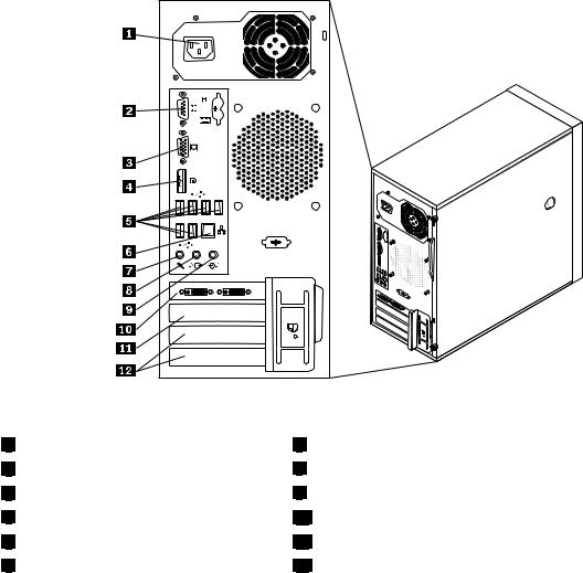
Figure 2. Rear connector locations
1 |
Power cord connector |
2 |
Serial port |
3 |
VGA monitor connector |
4 |
DisplayPort connector |
5 |
USB connectors (6) |
6 |
Ethernet connector |
7 Microphone connector
8 Audio line-out connector
9 Audio line-in connector
10 PCI Express x16 card slot
11 PCI Express x1 card slot
12 PCI card slots (2)
Connector |
Description |
Audio line-in connector |
Used to receive audio signals from an external audio device, such as a stereo |
|
system. When you attach an external audio device, a cable connects the audio |
|
line-out connector of the device to the audio line-in connector of the server. |
Audio line-out connector |
Used to send audio signals from the server to external devices, such as powered |
|
stereo speakers (speakers with built-in amplifiers), headphones, multimedia |
|
keyboards, or the audio line-in connector on a stereo system or other external |
|
recording device. |
DisplayPort connector |
Used to attach a high-performance monitor, a direct-drive monitor, or other devices |
|
that use a DisplayPort connector. |
Ethernet connector |
Used to attach an Ethernet cable for a local area network (LAN). |
|
Note: To operate the server within FCC Class B limits, use a Category 5 Ethernet |
|
cable. |
Microphone connector |
Used to attach a microphone to your server when you want to record sound or if |
|
you use speech-recognition software. |
Serial port |
Used to attach an external modem, a serial printer, or other devices that use a |
|
9-pin serial port. |
24 ThinkServerHardware Maintenance Manual
 Loading...