

Page 1

ThinkCentre
HardwareMaintenanceManual
MachineTypes:3656,3658,7057,7061,7062,7090,7092,9342,
9344,9353,9354,9421,9426,9485,9486,9623,9624,9625,9705,
9707,9786,9787,9795,9804,9935,9945,9946,and9953.
Page 2

Page 3

ThinkCentre
HardwareMaintenanceManual
MachineTypes:3656,3658,7057,7061,7062,7090,7092,9342,
9344,9353,9354,9421,9426,9485,9486,9623,9624,9625,9705,
9707,9786,9787,9795,9804,9935,9945,9946,and9953.
Page 4

Note:Beforeusingthisinformationandtheproductitsupports,besuretoreadtheinformationunderAppendixA
"Notices"onpage471.
ThirteenthEdition(July2010)
©CopyrightLenovo2008,2010.
LENOVOproducts,data,computersoftware,andserviceshavebeendevelopedexclusivelyatprivateexpenseandare
soldtogovernmentalentitiesascommercialitemsasdenedby48C.F.R.2.101withlimitedandrestrictedrightsto
use,reproductionanddisclosure.
LIMITEDANDRESTRICTEDRIGHTSNOTICE:Ifproducts,data,computersoftware,orservicesaredeliveredpursuant
aGeneralServicesAdministration²GSA²contract,use,reproduction,ordisclosureissubjecttorestrictionssetforth
inContractNo.GS-35F-05925.
Page 5

Contents
Chapter1.Aboutthismanual.....1
ImportantSafetyInformation..........1
ImportantinformationaboutreplacingRoHS
compliantFRUs...............1
Chapter2.Safetyinformation.....3
Generalsafety................3
Electricalsafety...............3
Voltage-selectionswitch............5
Safetyinspectionguide............5
Handlingelectrostaticdischarge-sensitive
devices..................6
Groundingrequirements............6
Safetynotices(multi-lingualtranslations).....6
Chapter3.Generalinformation....29
TheThinkVantageProductivityCenterprogram..29
Additionalinformationresources.......29
Specications...............29
Formachinetypes:7057,7062,7092,9342,
9344,9354,9426,9486,9624,9707,9787,
9804,9945..............29
Formachinetypes:7061,7090,9353,9421,
9485,9623,9625,9705,9786,9795,9935,
9946,9953..............29
Chapter4.GeneralCheckout.....31
Problemdeterminationtips..........31
Chapter5.Diagnostics........33
LenovoSystemToolbox...........33
PC-DoctorforWindowsPE..........33
RunningdiagnosticsfromtheRescueand
Recoveryworkspace..........33
PC-DoctorforDOS.............34
CreatingadiagnosticCDimage......34
Creatingdiagnosticdiskettes.......34
RunningdiagnosticsfromtheCDor
diskettes...............34
Navigatingthroughthediagnostics
programs...............35
Runningtests.............35
Viewingthetestlog...........36
Chapter6.UsingtheSetupUtility..39
StartingtheSetupUtilityprogram.......39
Viewingandchangingsettings........39
Usingpasswords..............39
Passwordconsiderations.........39
UserPassword.............40
AdministratorPassword.........40
Setting,changing,anddeletingapassword.40
Enablingordisablingadevice........40
Selectingastartupdevice..........41
Selectingatemporarystartupdevice....41
Selectingorchangingthestartupdevice
sequence...............41
ExitingfromtheSetupUtilityprogram.....41
Chapter7.Symptom-to-FRUIndex.43
Harddiskdrivebooterror..........43
PowerSupplyProblems...........43
Diagnosticerrorcodes...........44
Beepsymptoms..............61
POSTerrorcodes.............62
Miscellaneouserrormessages........63
Undeterminedproblems...........65
Chapter8.ReplacingFRUs(Types
7061,7090,9353,9421,9485,9623,
9625,9705,9786,9795,9935,9946,
9953)..................67
Locatingcontrolsandconnectorsonthefrontof
yourcomputer...............67
Rearconnectors..............67
Removingthecover............68
Locations.................69
Locatingpartsonthesystemboard......71
Removingandreplacingthefrontbezel.....71
Replacingthepowersupply.........72
Replacingthesystemboard.........73
Replacingthemicroprocessor........77
Replacingamemorymodule.........79
ReplacingaPCIadaptercard.........80
Replacingtheharddiskdrive.........82
Replacinganopticaldrive..........84
Replacingthediskettedrive.........85
Replacingtherearfanassembly........86
Replacingthefrontfanassembly.......87
Replacingthefrontaudio/USBassembly....89
Replacingthepowerswitch/LEDassembly...89
ReplacingtheCMOSbattery.........90
CompletingtheFRUreplacement.......91
Chapter9.ReplacingFRUs(Types
7057,7062,7092,9342,9344,9354,
©CopyrightLenovo2008,2010
v
Page 6

9426,9486,9624,9707,9787,9804,
9945)..................93
Rearconnectors..............93
Removingthecover............94
Locations.................94
Locatingpartsonthesystemboard......95
Accessingsystemboardcomponentsanddrives.96
Replacingamemorymodule.........97
ReplacingtheCMOSbattery.........98
Replacingthepowersupply.........99
Replacingthesystemboard.........100
Replacingthemicroprocessor........104
Replacingtheharddiskdrive.........106
Replacinganopticaldrive..........108
Replacingthediskettedrive.........109
Replacingthepowerswitch/LEDassembly...109
Replacingthefrontpanelcard........110
Replacingthesystemfanassembly......111
ReplacingaPCIadaptercard.........112
CompletingtheFRUreplacement.......113
Chapter10.FRUlists........115
MachineType3656.............115
MachineType3658.............128
MachineType7057.............141
MachineType7061.............155
MachineType7062.............168
MachineType7090.............182
MachineType7092.............195
MachineType9342.............208
MachineType9344.............221
MachineType9353.............234
MachineType9354.............247
MachineType9421.............260
MachineType9426.............273
MachineType9485.............286
MachineType9486.............302
MachineType9623.............318
MachineType9624.............331
MachineType9625.............344
MachineType9705.............358
MachineType9707.............371
MachineType9795.............385
MachineType9804.............398
MachineType9935.............411
MachineType9945.............425
MachineType9946.............439
MachineType9953.............452
Chapter11.AdditionalService
Information.............467
Securityfeatures..............467
HardwarecontrolledPasswords......467
Operatingsystempassword.......467
Vitalproductdata............467
BIOSlevels................467
Flashupdateprocedures..........467
Updating(ashing)BIOSfromadiskette...468
RecoveringfromaPOST/BIOSupdatefailure..468
Powermanagement............468
Automaticcongurationandpowerinterface
(ACPI)BIOS..............468
AutomaticPower-Onfeatures.......468
AppendixA.Notices........471
Televisionoutputnotice...........472
Trademarks................472
viThinkCentreHardwareMaintenanceManual
Page 7
Chapter1.Aboutthismanual
ThismanualcontainsserviceandreferenceinformationforThinkCentre®computerslistedonthecover.Itis
intendedonlyfortrainedservicerswhoarefamiliarwithLenovocomputerproducts.
BeforeservicingaLenovoproduct,besuretoreadtheSafetyInformation.SeeChapter2"Safety
information"onpage3
TheSymptom-to-FRUIndexandAdditionalServiceInformationchaptersarenotspecictoanymachine
typeandareapplicabletoallThinkCentrecomputers.
ThismanualincludesacompleteFRUpartnumberlistingforeachmachinetypeandmodellistedonthe
cover.Ifyouhaveinternetaccess,FRUpartnumbersarealsoavailableat:
http:/www.lenovo.com/support
ImportantSafetyInformation
Besuretoreadallcautionanddangerstatementsinthisbookbeforeperforminganyoftheinstructions.
VeuillezliretouteslesconsignesdetypeDANGERetA TTENTIONduprésentdocumentavantd'exécuter
lesinstructions.
LesenSieunbedingtalleHinweisevomTyp"ACHTUNG"oder"VORSICHT"indieserDokumentation,bevor
SieirgendwelcheVorgängedurchführen
.
LeggereleistruzioniintrodottedaATTENZIONEePERICOLOpresentinelmanualeprimadieseguireuna
qualsiasidelleistruzioni
Certique-sedelertodasasinstruçõesdecuidadoeperigonestemanualantesdeexecutarqualquer
umadasinstruções
Esimportantequeleatodaslasdeclaracionesdeprecauciónydepeligrodeestemanualantesdeseguir
lasinstrucciones.
ImportantinformationaboutreplacingRoHScompliantFRUs
RoHS,TheRestrictionofHazardousSubstancesinElectricalandElectronicEquipmentDirective
(2002/95/EC)isaEuropeanUnionlegalrequirementaffectingtheglobalelectronicsindustry.RoHS
requirementsmustbeimplementedonLenovoproductsplacedonthemarketandsoldinthe
EuropeanUnionafterJune2006.ProductsonthemarketbeforeJune2006arenotrequiredto
haveRoHScompliantparts.Ifthepartsarenotcompliantoriginally,replacementpartscanalso
©CopyrightLenovo2008,2010
1
Page 8
benoncompliant,butinallcases,ifthepartsarecompliant,thereplacementpartsmustalsobe
compliant.
Note:RoHSandnon-RoHSFRUpartnumberswiththesametandfunctionareidentiedwithunique
FRUpartnumbers.
LenovoplanstotransitiontoRoHScompliancewellbeforetheimplementationdateandexpectsitssuppliers
tobereadytosupportLenovo'srequirementsandscheduleintheEU.Productssoldin2005,willcontain
someRoHScompliantFRUs.ThefollowingstatementpertainstotheseproductsandanyproductLenovo
producescontainingRoHScompliantparts.
RoHScompliantThinkCentrepartshaveuniqueFRUpartnumbers.BeforeorafterJune,2006,failedRoHS
compliantpartsmustalwaysbereplacedusingRoHScompliantFRUs,soonlytheFRUsidentiedas
compliantinthesystemHMMordirectsubstitutionsforthoseFRUscanbeused.
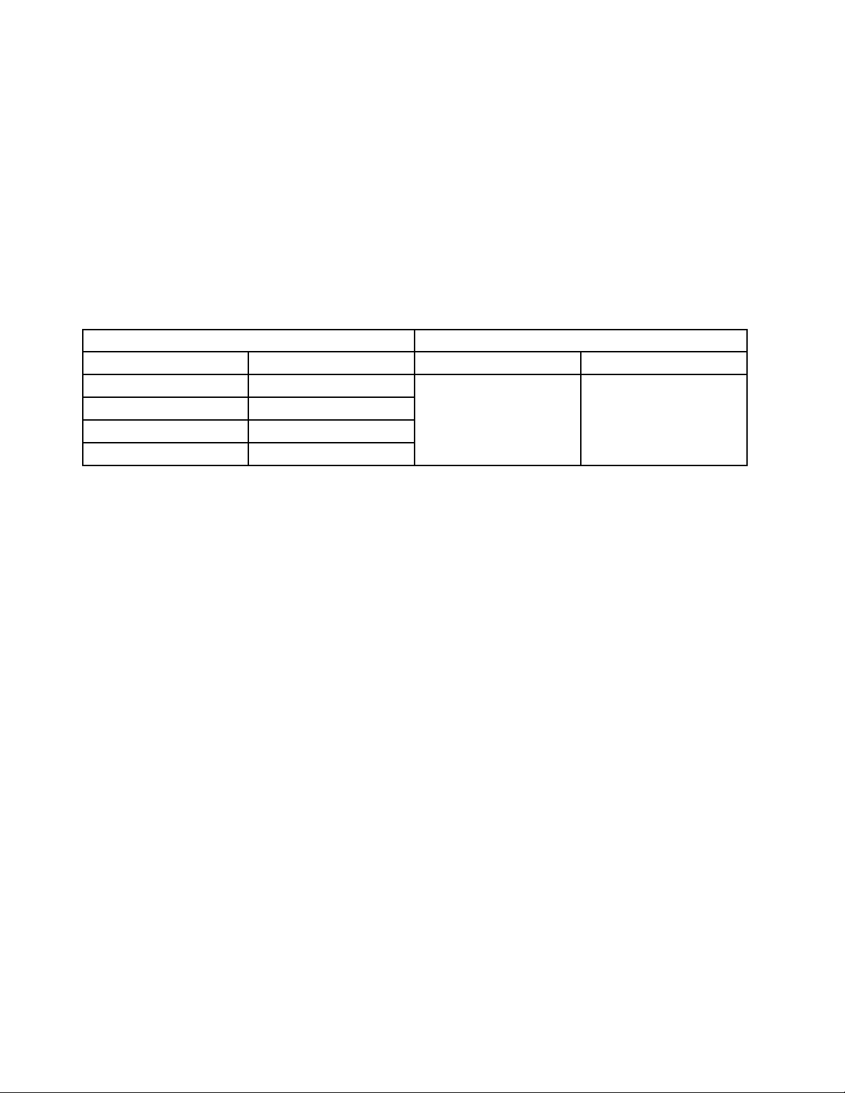
ProductsmarketedbeforeJune2006ProductsmarketedafterJune2006
Currentororiginalpart
Non-RoHSCanbeNon-RoHS
Non-RoHSCanbeRoHS
Non-RoHSCansubtoRoHS
RoHSMustbeRoHS
ReplacementFRU
Currentororiginalpart
MustbeRoHSMustbeRoHS
ReplacementFRU
Note:AdirectsubstitutionisapartwithadifferentFRUpartnumberthatisautomaticallyshippedbythe
distributioncenteratthetimeoforder.
2ThinkCentreHardwareMaintenanceManual
Page 9

Chapter2.Safetyinformation
Thischaptercontainsthesafetyinformationthatyouneedtobefamiliarwithbeforeservicingacomputer.
Generalsafety
Followtheserulestoensuregeneralsafety:
•Observegoodhousekeepingintheareaofthemachinesduringandaftermaintenance.
•Whenliftinganyheavyobject:
1.Ensureyoucanstandsafelywithoutslipping.
2.Distributetheweightoftheobjectequallybetweenyourfeet.
3.Useaslowliftingforce.Nevermovesuddenlyortwistwhenyouattempttolift.
4.Liftbystandingorbypushingupwithyourlegmuscles;thisactionremovesthestrainfromthe
musclesinyourback.Donotattempttoliftanyobjectsthatweighmorethan16kg(35lb)orobjects
thatyouthinkaretooheavyforyou.
•Donotperformanyactionthatcauseshazardstothecustomer,orthatmakestheequipmentunsafe.
•Beforeyoustartthemachine,ensurethatotherservicerepresentativesandthecustomer'spersonnelare
notinahazardousposition.
•Placeremovedcoversandotherpartsinasafeplace,awayfromallpersonnel,whileyouareservicing
themachine.
•Keepyourtoolcaseawayfromwalkareassothatotherpeoplewillnottripoverit.
•Donotwearlooseclothingthatcanbetrappedinthemovingpartsofamachine.Ensurethatyoursleeves
arefastenedorrolledupaboveyourelbows.Ifyourhairislong,fastenit.
•Inserttheendsofyournecktieorscarfinsideclothingorfastenitwithanonconductiveclip,approximately
8centimeters(3inches)fromtheend.
•Donotwearjewelry,chains,metal-frameeyeglasses,ormetalfastenersforyourclothing.
Remember:Metalobjectsaregoodelectricalconductors.
•Wearsafetyglasseswhenyouare:hammering,drillingsoldering,cuttingwire,attachingsprings,using
solvents,orworkinginanyotherconditionsthatmightbehazardoustoyoureyes.
•Afterservice,reinstallallsafetyshields,guards,labels,andgroundwires.Replaceanysafetydevice
thatiswornordefective.
•Reinstallallcoverscorrectlybeforereturningthemachinetothecustomer.
Electricalsafety
CAUTION:
Electricalcurrentfrompower,telephone,andcommunicationcablescanbehazardous.T oavoid
personalinjuryorequipmentdamage,disconnecttheattachedpowercords,telecommunication
systems,networks,andmodemsbeforeyouopentheserver/workstationcovers,unlessinstructed
otherwiseintheinstallationandcongurationprocedures.
Observethefollowingruleswhenworkingonelectricalequipment.
©CopyrightLenovo2008,2010
3
Page 10

Important:Useonlyapprovedtoolsandtestequipment.Somehandtoolshavehandlescoveredwithasoft
materialthatdoesnotinsulateyouwhenworkingwithliveelectricalcurrents.
Manycustomershave,neartheirequipment,rubberoormatsthatcontainsmallconductivebersto
decreaseelectrostaticdischarges.Donotusethistypeofmattoprotectyourselffromelectricalshock.
•Findtheroomemergencypower-off(EPO)switch,disconnectingswitch,orelectricaloutlet.Ifanelectrical
accidentoccurs,youcanthenoperatetheswitchorunplugthepowercordquickly.
•Donotworkaloneunderhazardousconditionsornearequipmentthathashazardousvoltages.
•Disconnectallpowerbefore:
–Performingamechanicalinspection
–Workingnearpowersupplies
–RemovingorinstallingFieldReplaceableUnits
•Beforeyoustarttoworkonthemachine,unplugthepowercord.Ifyoucannotunplugit,askthecustomer
topower-offthewallboxthatsuppliespowertothemachineandtolockthewallboxintheoffposition.
•Ifyouneedtoworkonamachinethathasexposedelectricalcircuits,observethefollowingprecautions:
–Ensurethatanotherperson,familiarwiththepower-offcontrols,isnearyou.
Remember:Anotherpersonmustbetheretoswitchoffthepower,ifnecessary.
–Useonlyonehandwhenworkingwithpowered-onelectricalequipment;keeptheotherhandinyour
pocketorbehindyourback.
Remember:Theremustbeacompletecircuittocauseelectricalshock.Byobservingtheaboverule,
youmaypreventacurrentfrompassingthroughyourbody.
–Whenusingtesters,setthecontrolscorrectlyandusetheapprovedprobeleadsandaccessoriesfor
thattester.
–Standonsuitablerubbermats(obtainedlocally,ifnecessary)toinsulateyoufromgroundssuchas
metaloorstripsandmachineframes.
Observethespecialsafetyprecautionswhenyouworkwithveryhighvoltages;theseinstructionsarein
thesafetysectionsofmaintenanceinformation.Useextremecarewhenmeasuringhighvoltages.
•Regularlyinspectandmaintainyourelectricalhandtoolsforsafeoperationalcondition.
•Donotusewornorbrokentoolsandtesters.
•Neverassumethatpowerhasbeendisconnectedfromacircuit.First,checkthatithasbeenpowered-off.
•Alwayslookcarefullyforpossiblehazardsinyourworkarea.Examplesofthesehazardsaremoistoors,
nongroundedpowerextensioncables,powersurges,andmissingsafetygrounds.
•Donottouchliveelectricalcircuitswiththereectivesurfaceofaplasticdentalmirror.Thesurfaceis
conductive;suchtouchingcancausepersonalinjuryandmachinedamage.
•Donotservicethefollowingpartswiththepoweronwhentheyareremovedfromtheirnormaloperating
placesinamachine:
–Powersupplyunits
–Pumps
–Blowersandfans
–Motorgenerators
andsimilarunits.(Thispracticeensurescorrectgroundingoftheunits.)
•Ifanelectricalaccidentoccurs:
–Usecaution;donotbecomeavictimyourself.
–Switchoffpower.
–Sendanotherpersontogetmedicalaid.
4ThinkCentreHardwareMaintenanceManual
Page 11

Voltage-selectionswitch
Somecomputersareequippedwithavoltage-selectionswitchlocatednearthepower-cordconnection
pointonthecomputer.Ifyourcomputerhasavoltage-selectionswitch,ensurethatyousettheswitchto
matchthevoltageavailableatyourelectricaloutlet.Settingthevoltage-selectionswitchincorrectlycan
causepermanentdamagetothecomputer.
Ifyourcomputerdoesnothaveavoltage-selectionswitch,yourcomputerisdesignedtooperateonlyatthe
voltageprovidedinthecountryorregionwherethecomputerwasoriginallypurchased.
Ifyourelocateyourcomputertoanothercountry,beawareofthefollowing:
•Ifyourcomputerdoesnothaveavoltage-selectionswitch,donotconnectthecomputertoanelectrical
outletuntilyouhaveveriedthatthevoltageprovidedisthesameasitwasinthecountryorregion
wherethecomputerwasoriginallypurchased.
•Ifyourcomputerhasavoltageselectionswitch,donotconnectthecomputertoanelectricaloutletuntil
youhaveveriedthatthevoltage-selectionswitchissettomatchthevoltageprovidedinthatcountry
orregion.
Ifyouarenotsureofthevoltageprovidedatyourelectricaloutlet,contactyourlocalelectriccompanyor
refertoofcialWebsitesorotherliteraturefortravelerstothecountryorregionwhereyouarelocated.
Safetyinspectionguide
Theintentofthisinspectionguideistoassistyouinidentifyingpotentiallyunsafeconditionsonthese
products.Eachmachine,asitwasdesignedandbuilt,hadrequiredsafetyitemsinstalledtoprotectusers
andservicepersonnelfrominjury.Thisguideaddressesonlythoseitems.However,goodjudgmentshould
beusedtoidentifypotentialsafetyhazardsduetoattachmentoffeaturesoroptionsnotcoveredbythis
inspectionguide.
Ifanyunsafeconditionsarepresent,youmustdeterminehowserioustheapparenthazardcouldbeand
whetheryoucancontinuewithoutrstcorrectingtheproblem.
Considertheseconditionsandthesafetyhazardstheypresent:
•Electricalhazards,especiallyprimarypower(primaryvoltageontheframecancauseseriousorfatal
electricalshock).
•Explosivehazards,suchasadamagedCRTfaceorbulgingcapacitor
•Mechanicalhazards,suchaslooseormissinghardware
Theguideconsistsofaseriesofstepspresentedinachecklist.Beginthecheckswiththepoweroff,and
thepowercorddisconnected.
Checklist:
1.Checkexteriorcoversfordamage(loose,broken,orsharpedges).
2.Power-offthecomputer.Disconnectthepowercord.
3.Checkthepowercordfor:
a.Athird-wiregroundconnectoringoodcondition.Useametertomeasurethird-wiregroundcontinuity
for0.1ohmorlessbetweentheexternalgroundpinandframeground.
b.Thepowercordshouldbetheappropriatetypeasspeciedinthepartslistings.
c.Insulationmustnotbefrayedorworn.
4.Removethecover.
Chapter2Safetyinformation5
Page 12

5.Checkforanyobviousalterations.Usegoodjudgmentastothesafetyofanyalterations.
6.Checkinsidetheunitforanyobviousunsafeconditions,suchasmetallings,contamination,wateror
otherliquids,orsignsofreorsmokedamage.
7.Checkforworn,frayed,orpinchedcables.
8.Checkthatthepower-supplycoverfasteners(screwsorrivets)havenotbeenremovedortamperedwith.
Handlingelectrostaticdischarge-sensitivedevices
Anycomputerpartcontainingtransistorsorintegratedcircuits(ICs)shouldbeconsideredsensitiveto
electrostaticdischarge(ESD).ESDdamagecanoccurwhenthereisadifferenceinchargebetweenobjects.
ProtectagainstESDdamagebyequalizingthechargesothatthemachine,thepart,theworkmat,andthe
personhandlingthepartareallatthesamecharge.
Notes:
1.Useproduct-specicESDprocedureswhentheyexceedtherequirementsnotedhere.
2.MakesurethattheESDprotectivedevicesyouusehavebeencertied(ISO9000)asfullyeffective.
WhenhandlingESD-sensitiveparts:
•Keepthepartsinprotectivepackagesuntiltheyareinsertedintotheproduct.
•Avoidcontactwithotherpeoplewhilehandlingthepart.
•Wearagroundedwriststrapagainstyourskintoeliminatestaticonyourbody.
•Preventthepartfromtouchingyourclothing.Mostclothingisinsulativeandretainsachargeevenwhen
youarewearingawriststrap.
•Usetheblacksideofagroundedworkmattoprovideastatic-freeworksurface.Thematisespecially
usefulwhenhandlingESD-sensitivedevices.
•Selectagroundingsystem,suchasthoselistedbelow,toprovideprotectionthatmeetsthespecic
servicerequirement.
Note:TheuseofagroundingsystemisdesirablebutnotrequiredtoprotectagainstESDdamage.
–AttachtheESDgroundcliptoanyframeground,groundbraid,orgreen-wireground.
–UseanESDcommongroundorreferencepointwhenworkingonadouble-insulatedor
battery-operatedsystem.Y oucanusecoaxorconnector-outsideshellsonthesesystems.
–Usetheroundground-prongoftheacplugonac-operatedcomputers.
Groundingrequirements
Electricalgroundingofthecomputerisrequiredforoperatorsafetyandcorrectsystemfunction.Proper
groundingoftheelectricaloutletcanbeveriedbyacertiedelectrician.
Safetynotices(multi-lingualtranslations)
Thecautionanddangersafetynoticesinthissectionareprovidedinthefollowinglanguages:
•English
•Arabic
•Brazilian/Portuguese
•Chinese(simplied)
•Chinese(traditional)
6ThinkCentreHardwareMaintenanceManual
Page 13
•French
•German
•Hebrew
•Italian
•Korean
•Spanish
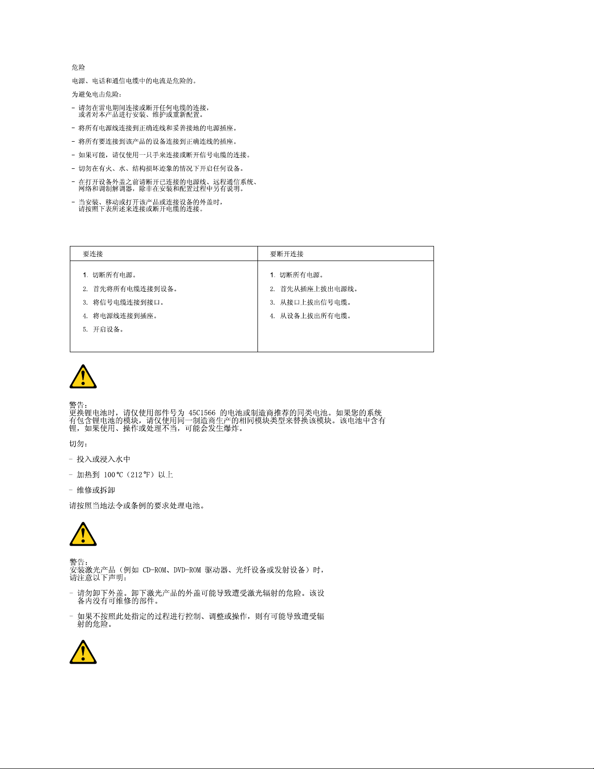
DANGER
Electricalcurrentfrompower,telephoneandcommunicationcablesishazardous.
Toavoidashockhazard:
•Donotconnectordisconnectanycablesorperforminstallation,maintenance,orreconguration
ofthisproductduringanelectricalstorm.
•Connectallpowercordstoaproperlywiredandgroundedelectricaloutlet.
•Connecttoproperlywiredoutletsanyequipmentthatwillbeattachedtothisproduct.
•Whenpossible,useonehandonlytoconnectordisconnectsignalcables.
•Neverturnonanyequipmentwhenthereisevidenceofre,water,orstructuraldamage.
•Disconnecttheattachedpowercords,telecommunicationssystems,networks,andmodems
beforeyouopenthedevicecovers,unlessinstructedotherwiseintheinstallationandconguration
procedures.
•Connectanddisconnectcablesasdescribedinthefollowingtableswheninstalling,moving,or
openingcoversonthisproductorattacheddevices.
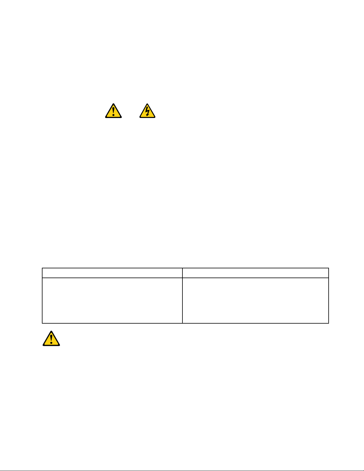
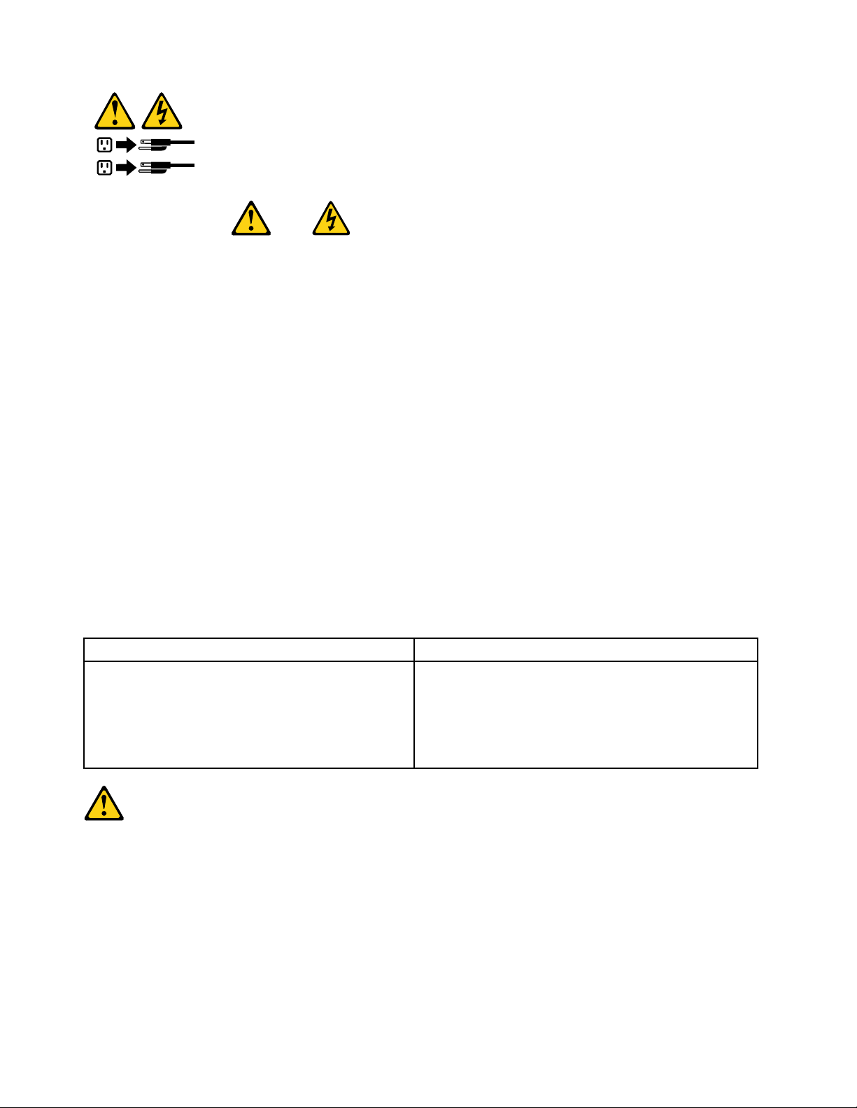
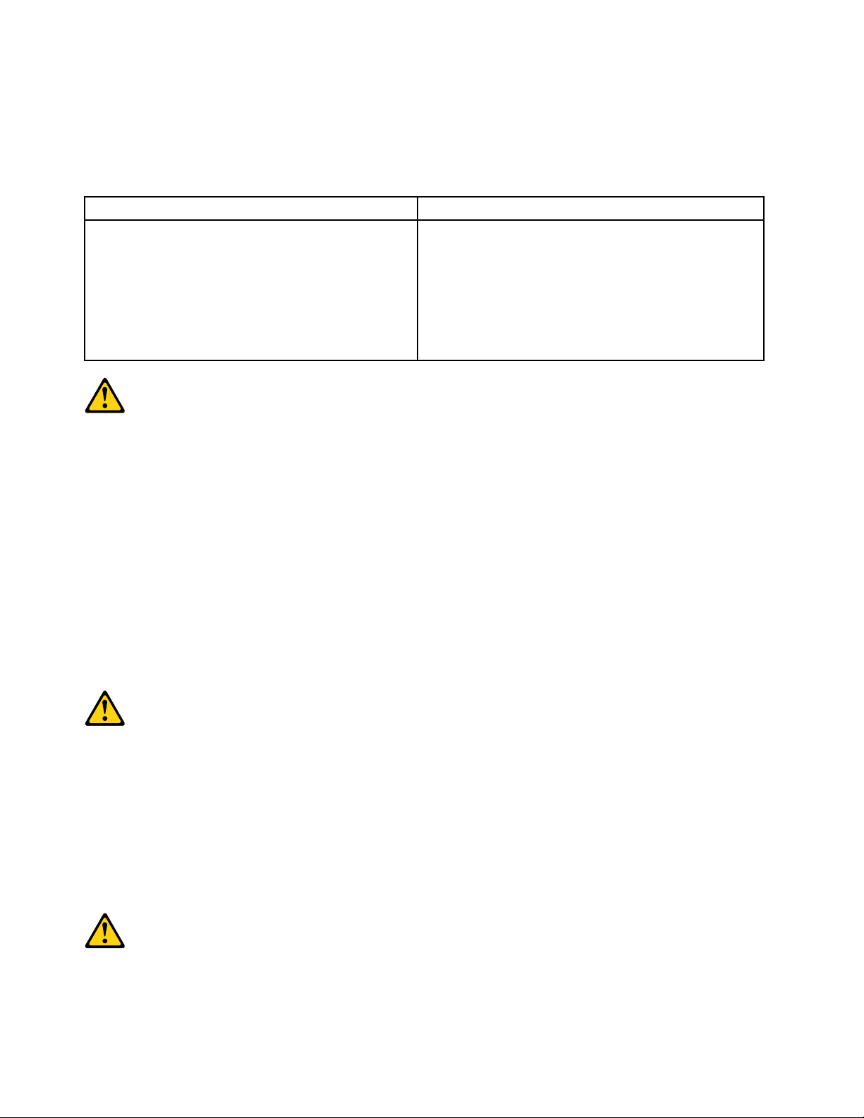
ToConnectToDisconnect
1.T urneverythingOFF.
2.First,attachallcablestodevices.
3.Attachsignalcablestoconnectors.
4.Attachpowercordstooutlet.
5.T urndeviceON.
1.T urneverythingOFF.
2.First,removepowercordsfromoutlet.
3.Removesignalcablesfromconnectors.
4.Removeallcablesfromdevices.
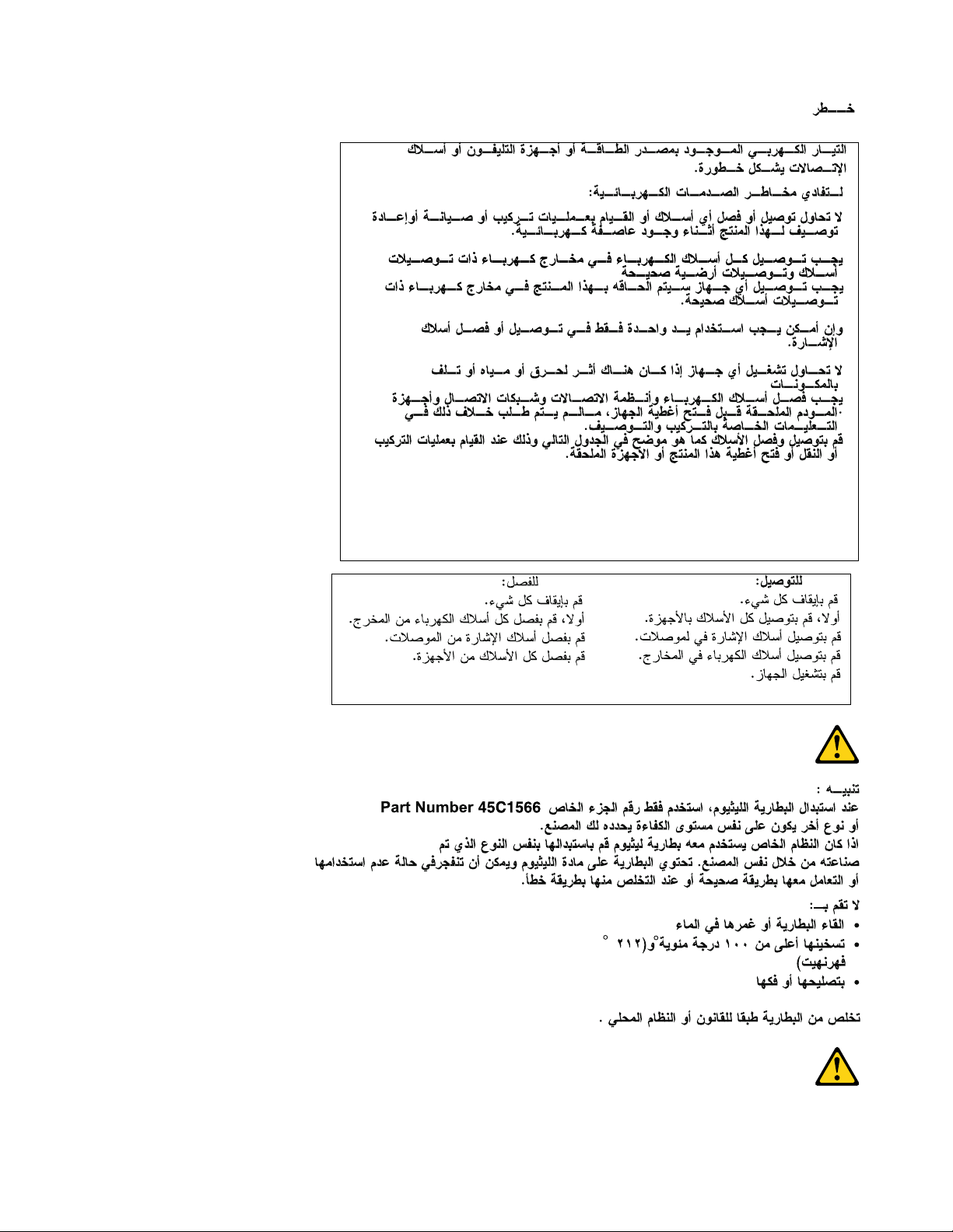
CAUTION:
Whenreplacingthelithiumbattery,useonlyPartNumber33F8354oranequivalenttypebattery
recommendedbythemanufacturer.Ifyoursystemhasamodulecontainingalithiumbattery,replace
itonlywiththesamemoduletypemadebythesamemanufacturer.Thebatterycontainslithiumand
canexplodeifnotproperlyused,handled,ordisposedof.
Donot:
•Throworimmerseintowater
•Heattomorethan100°C(212°F)
•Repairordisassemble
Chapter2Safetyinformation7
Page 14
Disposeofthebatteryasrequiredbylocalordinancesorregulations.
1
2
CAUTION:
Whenlaserproducts(suchasCD-ROMs,DVD-ROMdrives,beropticdevices,ortransmitters)are
installed,notethefollowing:
•Donotremovethecovers.Removingthecoversofthelaserproductcouldresultinexposureto
hazardouslaserradiation.Therearenoserviceablepartsinsidethedevice.
•Useofcontrolsoradjustmentsorperformanceofproceduresotherthanthosespeciedherein
mightresultinhazardousradiationexposure.
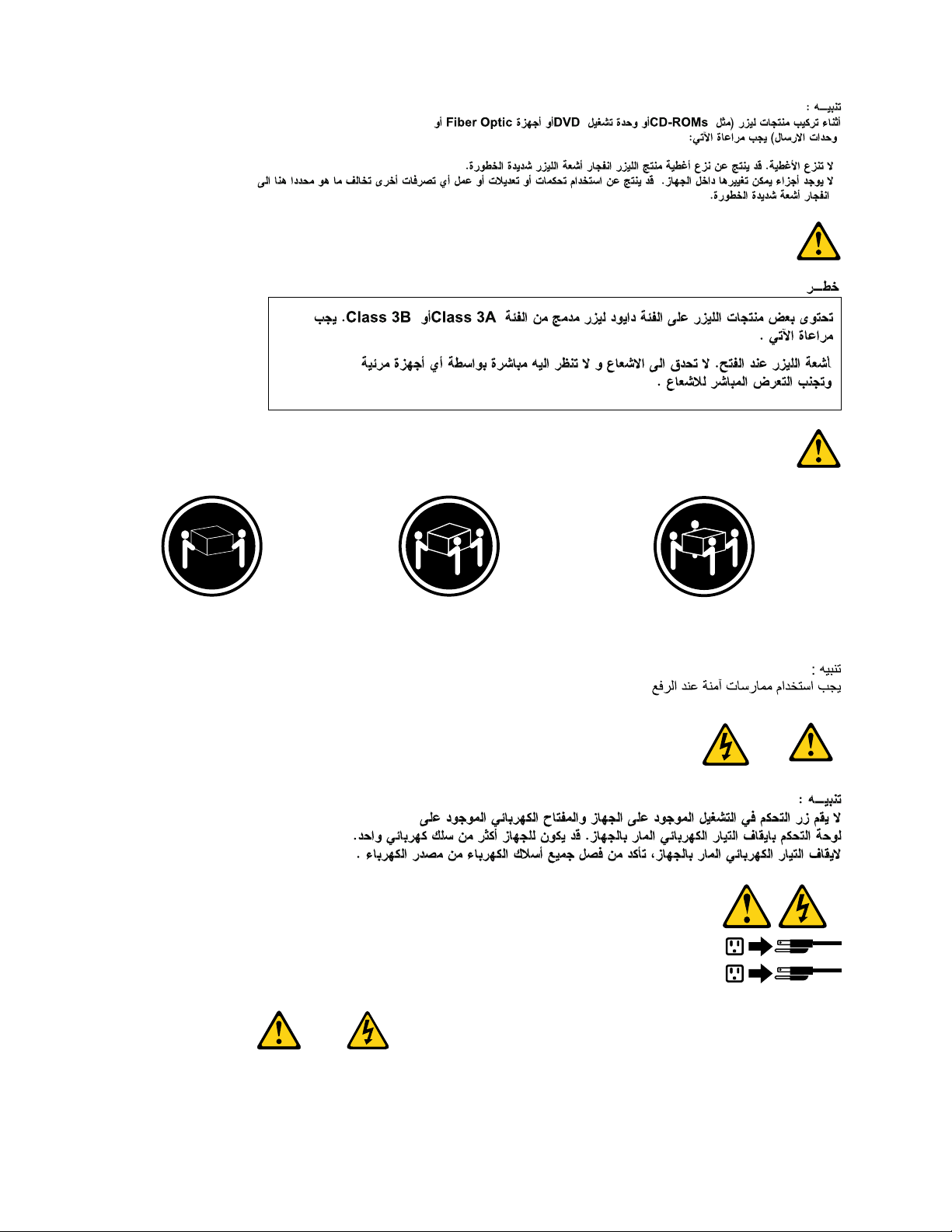
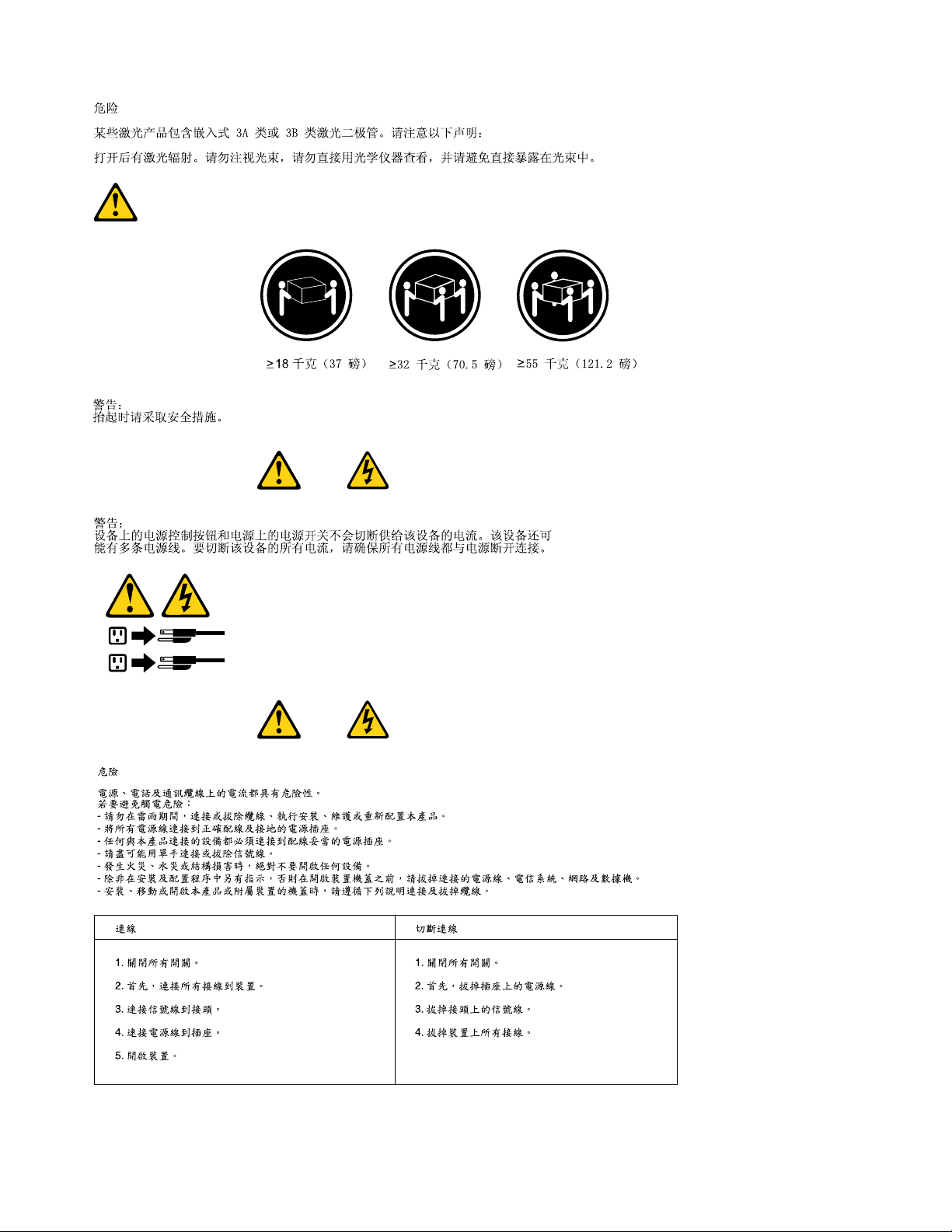
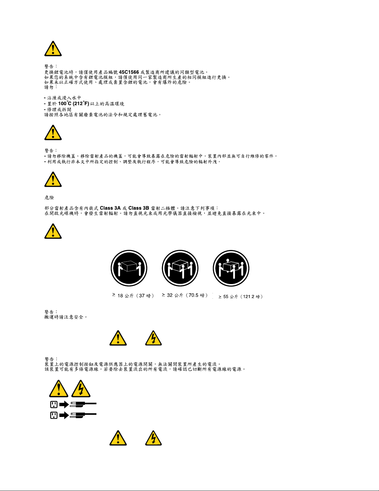
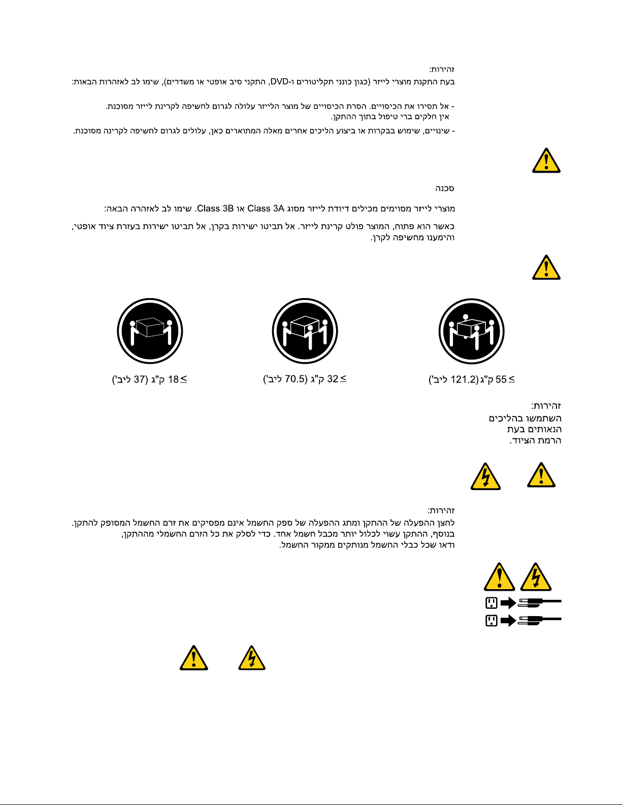
DANGER
SomelaserproductscontainanembeddedClass3AorClass3Blaserdiode.Notethefollowing:
Laserradiationwhenopen.Donotstareintothebeam,donotviewdirectlywithoptical
instruments,andavoiddirectexposuretothebeam.
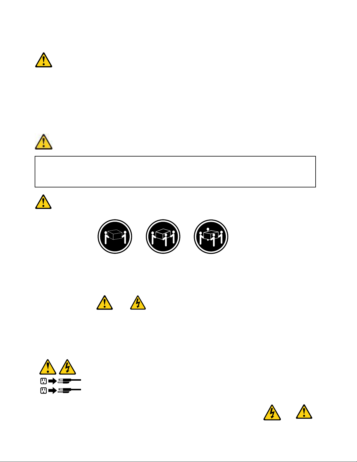
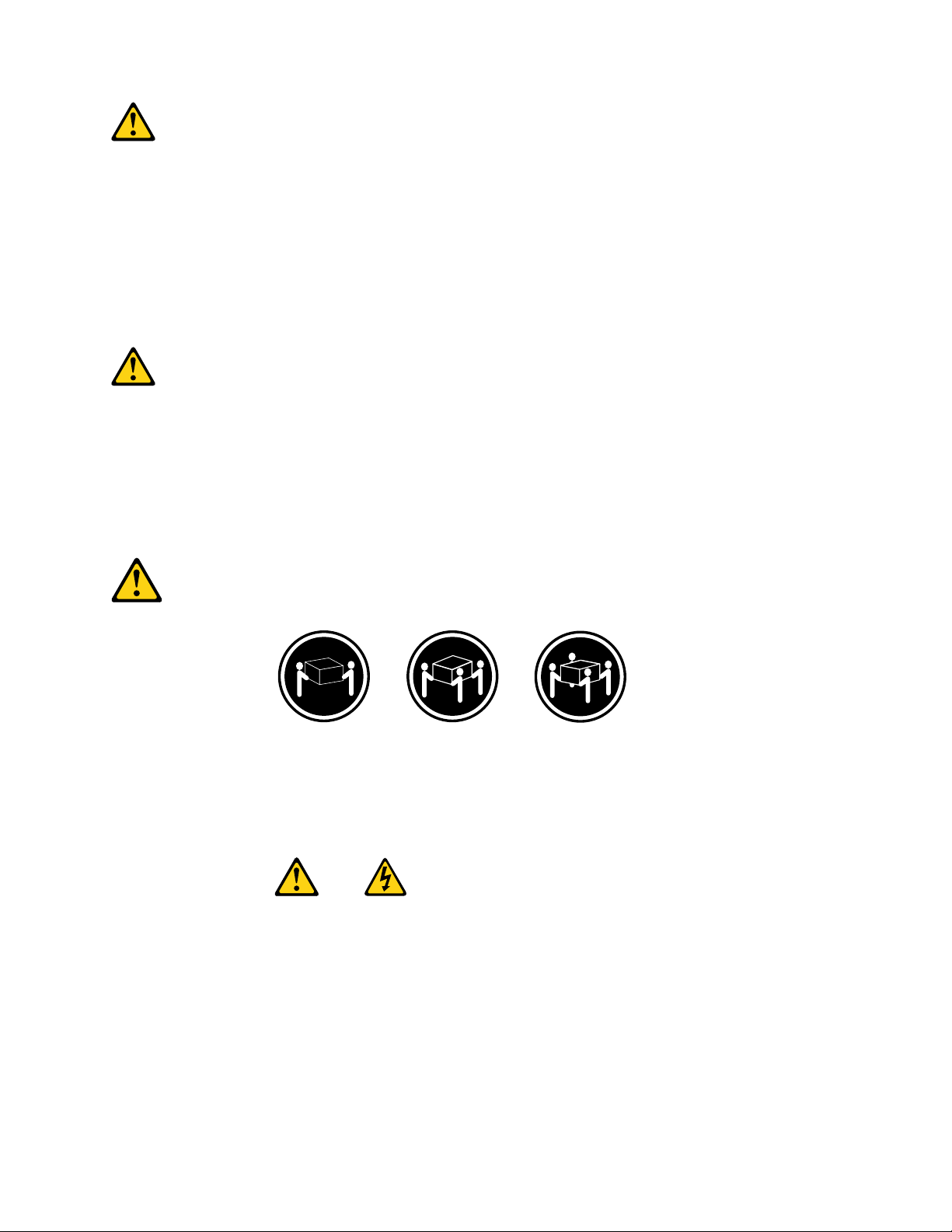
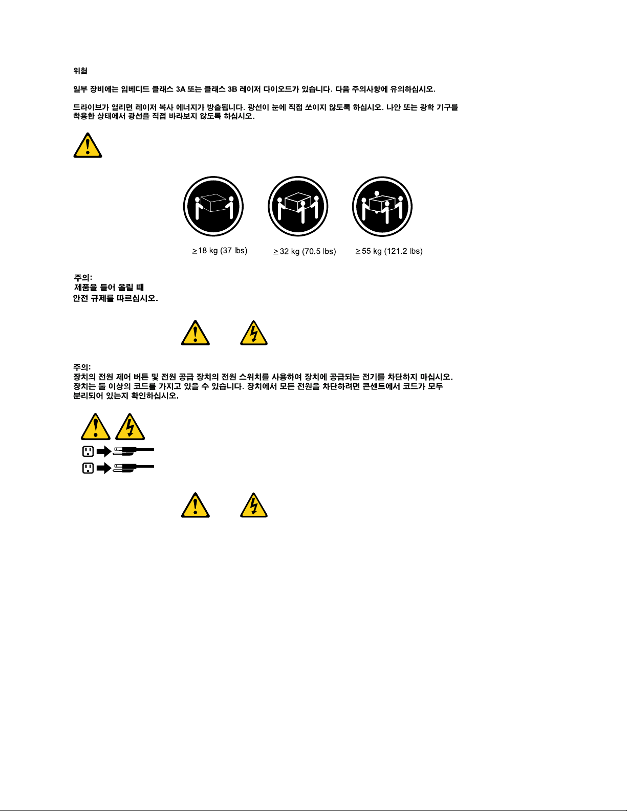
≥18kg(37lbs)≥32kg(70.5lbs)≥55kg(121.2lbs)
CAUTION:
Usesafepracticeswhenlifting.
CAUTION:
Thepowercontrolbuttononthedeviceandthepowerswitchonthepowersupplydonotturnoff
theelectricalcurrentsuppliedtothedevice.Thedevicealsomighthavemorethanonepower
cord.Toremoveallelectricalcurrentfromthedevice,ensurethatallpowercordsaredisconnected
fromthepowersource.
8ThinkCentreHardwareMaintenanceManual
Page 15
Chapter2Safetyinformation9
Page 16
≥18kg(37lbs)≥32kg(70.5lbs)≥55kg(121.2lbs)
1
2
PERIGO
10ThinkCentreHardwareMaintenanceManual
Page 17
Acorrenteelétricaprovenientedecabosdealimentação,detelefoneedecomunicaçõeséperigosa.
Paraevitarriscodechoqueelétrico:
•Nãoconectenemdesconectenenhumcaboouexecuteinstalação,manutençãooureconguração
desteprodutoduranteumatempestadecomraios.
•Conectetodososcabosdealimentaçãoatomadaselétricascorretamenteinstaladaseaterradas.
•T odoequipamentoqueforconectadoaesteprodutodeveserconectadoatomadascorretamente
instaladas.
•Quandopossível,utilizeapenasumadasmãosparaconectaroudesconectarcabosdesinal.
•Nuncaliguenenhumequipamentoquandohouverevidênciadefogo,águaoudanosestruturais.
•Antesdeabrirtampasdedispositivos,desconectecabosdealimentação,sistemasdetelecomunicação,
redesemodemsconectados,amenosqueespecicadodemaneiradiferentenosprocedimentosde
instalaçãoeconguração.
•Conecteedesconecteoscabosconformedescritonatabelaapresentadaaseguiraoinstalar,moverou
abrirtampasdesteprodutooudedispositivosconectados.
ParaConectar:ParaDesconectar:
1.DESLIGUETudo.
2.Primeiramente,conectetodososcabosaos
dispositivos.
3.Conecteoscabosdesinalaosconectores.
4.Conecteoscabosdealimentaçãoàstomadas.
5.LIGUEosdispositivos.
1.DESLIGUETudo.
2.Primeiramente,removaoscabosdealimentaçãodas
tomadas.
3.Removaoscabosdesinaldosconectores.
4.Removatodososcabosdosdispositivos.
CUIDADO:
Aosubstituirabateriadelítio,utilizeapenasumabateriacomNúmerodePeça33F8354ouumtipo
debateriaequivalenterecomendadopeloSeoseusistemapossuiummódulocomumabateriade
lítio,substitua-oapenasporummódulodomesmotipoedomesmofabricante.Abateriacontémlítio
epodeexplodirsenãoforutilizada,manuseadaoudescartadademaneiracorreta.
Não:
•Jogueoucoloquenaágua
•Aqueçaamaisde100°C(212°F)
•Consertenemdesmonte
Descarteabateriaconformerequeridopelasleisouregulamentoslocais.
PRECAUCIÓN:
Quandoprodutosalaser(comounidadesdeCD-ROMs,unidadesdeDVD-ROM,dispositivosdebraótica
outransmissores)estivereminstalados,observeoseguinte:
Chapter2Safetyinformation11
Page 18
•Nãoremovaastampas.Aremoçãodastampasdeumprodutoalaserpoderesultaremexposição
1
2
prejudicialàradiaçãodelaser.Nãoexistempeçasquepodemserconsertadasnointeriordodispositivo.
•Autilizaçãodecontrolesouajustesouaexecuçãodeprocedimentosdiferentesdosespecicadosaqui
poderesultaremexposiçãoprejudicialàradiação.
PERIGO
AlgunsprodutosalasercontêmdiododelaserintegradodaClasse3AoudaClasse3B.Observeoseguinte:
Radiaçãoalaserquandoaberto.Nãoolhediretamenteparaofeixeaolhonuoucominstrumentosópticose
eviteexposiçãodiretaaofeixe.
≥18kg(37lbs)≥32kg(70.5lbs)≥55kg(121.2lbs)
CUIDADO:
Utilizeprocedimentosdesegurançaparalevantarequipamentos.
CUIDADO:
Obotãodecontroledealimentaçãododispositivoeobotãoparaligar/desligardafontedealimentação
nãodesligamacorrenteelétricafornecidaaodispositivo.Odispositivotambémpodetermaisdeumcabo
dealimentação.Pararemovertodaacorrenteelétricadodispositivo,assegurequetodososcabosde
alimentaçãoestejamdesconectadosdafontedealimentação.
12ThinkCentreHardwareMaintenanceManual
Page 19
Chapter2Safetyinformation13
Page 20
1
2
14ThinkCentreHardwareMaintenanceManual
Page 21
1
2
Chapter2Safetyinformation15
Page 22
DANGER
Lecourantélectriqueprovenantdel'alimentation,dutéléphoneetdescâblesdetransmissionpeutprésenter
undanger.
Pourévitertoutrisquedechocélectrique:
•Nemanipulezaucuncâbleetn'effectuezaucuneopérationd'installation,d'entretienoudereconguration
deceproduitaucoursd'unorage.
•Brancheztouslescordonsd'alimentationsurunsocledeprisedecourantcorrectementcâbléetmisàla
terre.
•Branchezsurdessoclesdeprisedecourantcorrectementcâbléstoutéquipementconnectéàceproduit.
•Lorsquecelaestpossible,n'utilisezqu'uneseulemainpourconnecteroudéconnecterlescâbles
d'interface.
•Nemettezjamaisunéquipementsoustensionencasd'incendieoud'inondation,ouenprésencede
dommagesmatériels.
•Avantderetirerlescartersdel'unité,mettezcelle-cihorstensionetdéconnectezsescordons
d'alimentation,ainsiquelescâblesquilarelientauxréseaux,auxsystèmesdetélécommunicationetaux
modems(saufinstructioncontrairementionnéedanslesprocéduresd'installationetdeconguration).
•Lorsquevousinstallez,quevousdéplacez,ouquevousmanipulezleprésentproduitoudespériphériques
quiluisontraccordés,reportez-vousauxinstructionsci-dessouspourconnecteretdéconnecterles
différentscordons.
ConnexionDéconnexion
1.MettezlesunitésHORSTENSION.
2.Commencezparbranchertouslescordonssurles
unités.
3.Branchezlescâblesd'interfacesurdesconnecteurs.
4.Branchezlescordonsd'alimentationsurdesprises.
5.MettezlesunitésSOUSTENSION.
1.MettezlesunitésHORSTENSION.
2.Débranchezlescordonsd'alimentationdesprises.
3.Débranchezlescâblesd'interfacedesconnecteurs.
4.Débrancheztouslescâblesdesunités.
ATTENTION:
Remplacerlapileaulithiumusagéeparunepilederéférenceidentiqueexclusivement,(référence
33F8354),ousuivrelesinstructionsdufabricantquiendénitleséquivalences.Sivotresystèmeest
dotéd'unmodulecontenantunepileaulithium,vousdevezleremplaceruniquementparunmodule
identique,produitparlemêmefabricant.Lapilecontientdulithiumetpeutexploserencasde
mauvaiseutilisation,demauvaisemanipulationoudemiseaurebutinappropriée.
Nepas:
•lajeteràl'eau,
•l'exposeràdestempératuressupérieuresà100°C,
•chercheràlaréparerouàladémonter.
Nepasmettrelapileàlapoubelle.Pourlamiseaurebut,sereporteràlaréglementationenvigueur.
16ThinkCentreHardwareMaintenanceManual
Page 23
ATTENTION:
Sidesproduitsàlaser(telsquedesunitésdeCD-ROM,deDVD-ROM,desunitésàbresoptiques,ou
desémetteurs)sontinstallés,prenezconnaissancedesinformationssuivantes:
•Neretirezpaslecarter.Enouvrantl'unitédeCD-ROMoudeDVD-ROM,vousvousexposezau
rayonnementdangereuxdulaser.Aucunepiècedel'unitén'estréparable.
•Pourévitertoutrisqued'expositionaurayonlaser,respectezlesconsignesderéglageet
d'utilisationdescommandes,ainsiquelesprocéduresdécritesdansleprésentmanuel.
DANGER
Certainsproduitsàlasercontiennentunediodeàlaserintégréedeclasse3Aou3B.Prenez
connaissancedesinformationssuivantes:
Rayonnementlaserlorsquelecarterestouvert.Eviteztouteexpositiondirecteaurayonlaser.Evitez
deregarderxementlefaisceauoudel'observeràl'aided'instrumentsoptiques.
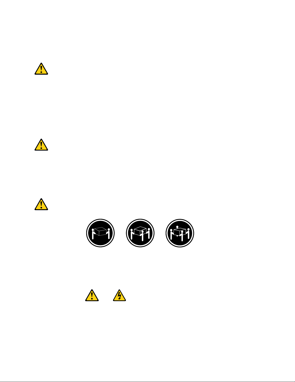
≥18kg(37lbs)≥32kg(70.5lbs)≥55kg(121.2lbs)
ATTENTION:
Soulevezlamachineavecprécaution.
ATTENTION:
L'interrupteurdecontrôled'alimentationdel'unitéetl'interrupteurdublocd'alimentationnecoupent
paslecourantélectriquealimentantl'unité.Enoutre,lesystèmepeutêtreéquipédeplusieurs
cordonsd'alimentation.Pourmettrel'unitéhorstension,vousdevezdéconnectertouslescordons
delasourced'alimentation.
Chapter2Safetyinformation17
Page 24
1
2
VORSICHT
AnNetz-,Telefon-undDatenleitungenkönnengefährlicheSpannungenanliegen.
AusSicherheitsgründen:
•BeiGewitterandiesemGerätkeineKabelanschließenoderlösen.FernerkeineInstallations-,
Wartungs-oderRekongurationsarbeitendurchführen.
•GerätnuraneineSchutzkontaktsteckdosemitordnungsgemäßgeerdetemSchutzkontakt
anschließen.
•AlleangeschlossenenGeräteebenfallsanSchutzkontaktsteckdosenmitordnungsgemäß
geerdetemSchutzkontaktanschließen.
•DieSignalkabelnachMöglichkeiteinhändiganschließenoderlösen,umeinenStromschlagdurch
BerührenvonOberächenmitunterschiedlichemelektrischemPotenzialzuvermeiden.
•Geräteniemalseinschalten,wennHinweiseaufFeuer,WasseroderGebäudeschädenvorliegen.
•DieVerbindungzudenangeschlossenenNetzkabeln,Telekommunikationssystemen,Netzwerken
undModemsistvordemÖffnendesGehäuseszuunterbrechen,sofernindenInstallations-und
KongurationsprozedurenkeineanderslautendenAnweisungenenthaltensind.
•ZumInstallieren,TransportierenundÖffnenderAbdeckungendesComputersoderder
angeschlossenenEinheitendieKabelgemäßderfolgendenTabelleanschließenundabziehen.
ZumAnschließenderKabelgehenSiewiefolgtvorZumAbziehenderKabelgehenSiewiefolgtvor
1.SchaltenSiealleEinheitenAUS.
2.SchließenSieerstalleKabelandieEinheitenan.
3.SchließenSiedieSignalkabelandieBuchsenan.
4.SchließenSiedieNetzkabelandieSteckdosean.
5.SchaltenSiedieEinheitEIN.
1.SchaltenSiealleEinheitenAUS.
2.ZiehenSiezuerstalleNetzkabelausden
Netzsteckdosen.
3.ZiehenSiedieSignalkabelausdenBuchsen.
4.ZiehenSiealleKabelvondenEinheitenab.
CAUTION:
EineverbrauchteLithiumbatterienurdurcheineBatteriemitderTeilenummer33F8354odereine
gleichwertige,vomHerstellerempfohleneBatterieersetzen.EnthältdasSystemeinModulmiteiner
Lithiumbatterie,diesesnurdurcheinModuldesselbenT ypsundvondemselbenHerstellerersetzen.
DieBatterieenthältLithiumundkannbeiunsachgemäßerVerwendung,HandhabungoderEntsorgung
explodieren.
DieBatterienicht:
•mitWasserinBerührungbringen.
18ThinkCentreHardwareMaintenanceManual
Page 25
•über100Cerhitzen.
•reparierenoderzerlegen.
DieörtlichenBestimmungenfürdieEntsorgungvonSondermüllbeachten.
ACHTUNG:
BeiderInstallationvonLasergeräten(wieCD-ROM-Laufwerken,DVD-aufwerken,Einheitenmit
LichtwellenleitertechnikoderSendern)Folgendesbeachten:
•DieAbdeckungennichtentfernen.DurchEntfernenderAbdeckungendesLasergerätskönnen
gefährlicheLaserstrahlungenfreigesetztwerden.DasGerätenthältkeinezuwartendenTeile.
•WerdenSteuerelemente,EinstellungenoderDurchführungenvonProzedurenandersalshier
angegebenverwendet,kanngefährlicheLaserstrahlungauftreten.
VORSICHT
EinigeLasergeräteenthalteneineLaserdiodederKlasse3Aoder3B.BeachtenSieFolgendes:
LaserstrahlungbeigeöffneterVerkleidung.NichtindenStrahlblicken.KeineLupenoderSpiegel
verwenden.Strahlungsbereichmeiden.
≥18kg(37lbs)≥32kg(70.5lbs)≥55kg(121.2lbs)
ACHTUNG:
ArbeitsschutzrichtlinienbeimAnhebenderMaschinebeachten.
ACHTUNG:
MitdemNetzschalteranderEinheitundamNetzteilwirddieStromversorgungfürdieEinheit
nichtunterbrochen.DieEinheitkannauchmitmehrerenNetzkabelnausgestattetsein.Umdie
StromversorgungfürdieEinheitvollständigzuunterbrechen,müssenallezumGerätführenden
NetzkabelvomNetzgetrenntwerden.
Chapter2Safetyinformation19
Page 26
1
2
20ThinkCentreHardwareMaintenanceManual
Page 27
1
2
PERICOLO
Lacorrenteelettricaprovenientedaicavidialimentazione,deltelefonoedicomunicazionepuòessere
pericolosa.
Chapter2Safetyinformation21
Page 28
Perevitareilrischiodiscosseelettriche:
•Noncollegareoscollegarequalsiasicavooppureeffettuarel'installazione,lamanutenzioneola
ricongurazionedelprodottoduranteuntemporale.
•Collegaretuttiilielettriciaunapresadialimentazionecorrettamentecablataedotatadimessaa
terra.
•Collegareallepreseelettricheappropriatetutteleapparecchiaturecheverrannoutilizzateper
questoprodotto.
•Sepossibile,utilizzaresolounamanopercollegareoscollegareicavidisegnale.
•Nonaccendereassolutamenteapparecchiatureinpresenzadiincendi,perdited'acquaodanno
strutturale.
•Scollegareicavidialimentazione,isistemiditelecomunicazione,leretieilmodemprimadi
aprireicoperchideldispositivo,salvoistruzionicontrarierelativealleprocedurediinstallazionee
congurazione.
•Collegareescollegareicavicomedescrittonellaseguentetabellaquandovengonoeffettuate
operazionidiinstallazione,spostamentooaperturadeicoperchidiquestoprodottoodelleunità
collegate.
PercollegarsiPerscollegarsi
1.SPEGNEREleapparecchiature.
2.Innanzitutto,collegaretuttiicavialleunità.
3.Collegareicavidisegnaleaiconnettori.
4.Collegareicavidialimentazioneallapresa.
5.Accenderel'unità.
1.SPEGNEREleapparecchiature.
2.Innanzitutto,rimuovereicavidialimentazionedalla
presa.
3.Rimuovereicavidisegnaledaiconnettori.
4.Rimuoveretuttiicavidalleunità.
ATTENZIONE:
Quandosisostituiscelabatteriaallitio,utilizzaresoloilNumeroparte33F8354ountipodibatteria
equivalenteconsigliatodalproduttore.Sesulsistemaèpresenteunmodulochecontieneunabatteria
allitio,sostituirlosoloconuntipodimodulodellostessotipodellastessacasadiproduzione.La
batteriacontienelitioepuòesplodereseusata,maneggiataosmaltitainmodononcorretto.
Non:
•Gettareoimmergerelabatterianell'acqua
•Riscaldarlaadunatemperaturasuperioreai100gradiC(212gradiF)
•Smontarla,ricaricarlaotentarediripararla
Lebatterieusatevannosmaltiteinaccordoallanormativainvigore(DPR915/82esuccessive
disposizioniedisposizionilocali).
ATTENZIONE:
Quandovengonoinstallatiprodottilaser(qualiCD-ROM,unitàDVD-ROM,unitàabreotticheo
trasmittenti),tenerpresentequantosegue:
22ThinkCentreHardwareMaintenanceManual
Page 29
•Nonrimuovereglisportelli.L'aperturadiun'unitàlaserpuòdeterminarel'esposizionearadiazioni
1
2
laserpericolose.All'internodell'unitànonvisonopartisucuieffettuarel'assistenzatecnica.
•L'utilizzodicontrolli,regolazioniol'esecuzionediprocedurenondescrittinelpresentemanuale
possonoprovocarel'esposizionearadiazionipericolose.
PERICOLO
AlcuneunitàlasercontengonoundiodolaserdiClasse3AoClasse3B.Tenerpresentequantosegue:
Aprendol'unitàvengonoemesseradiazionilaser.Nonssareilfascio,nonguardarlodirettamente
construmentiotticiedevitarel'esposizionealfascio.
≥18kg(37lbs)≥32kg(70.5lbs)≥55kg(121.2lbs)
ATTENZIONE:
Prestareattenzionenelsollevarel'apparecchiatura.
ATTENZIONE:
Ilpulsantedicontrollodell'alimentazionepresentesull'unitàel'interruttoredell'alimentatorenon
disattivanol'alimentazionecorrentefornitaall'unità.E'possibilechel'unitàdispongadipiùcavidi
alimentazione.Perdisattivarel'alimentazionedall'unità,accertarsichetuttiicavidialimentazione
sianoscollegatidallafontedialimentazione.
Chapter2Safetyinformation23
Page 30
24ThinkCentreHardwareMaintenanceManual
Page 31
1
2
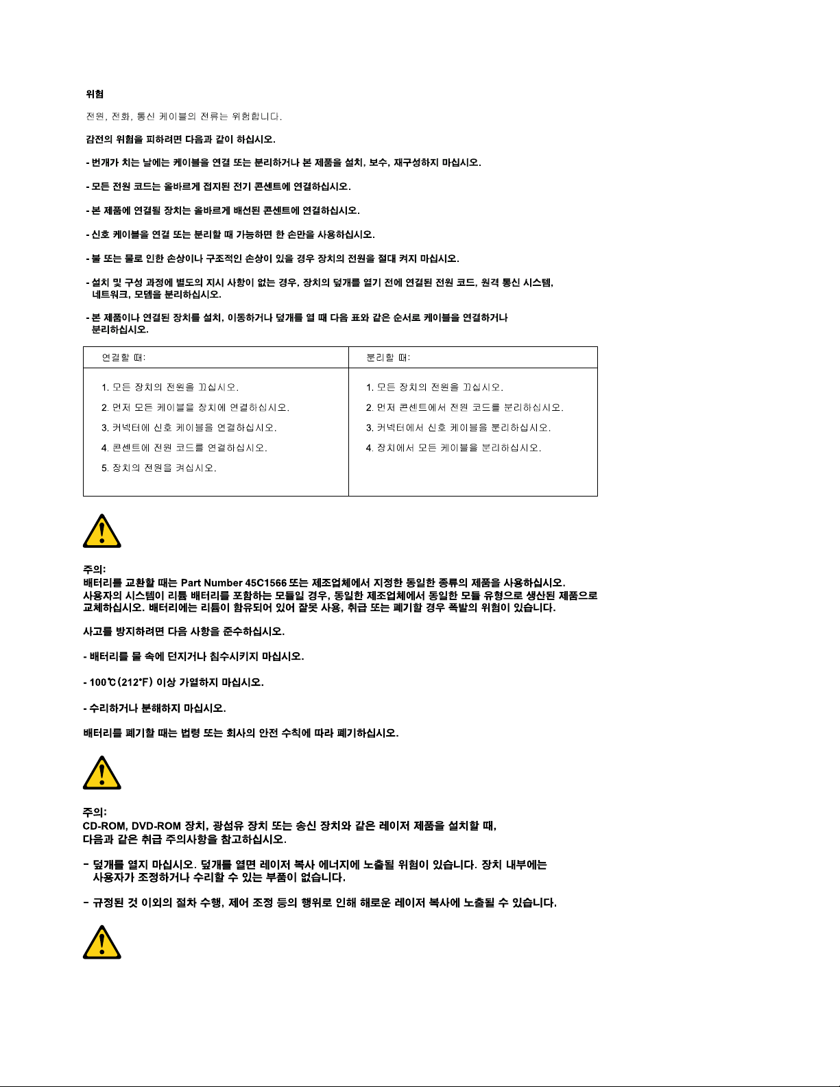
PELIGRO
Lacorrienteeléctricaprocedentedecablesdealimentación,teléfonosycablesdecomunicaciónpuede
serpeligrosa.
Paraevitarelriesgodedescargaeléctrica:
•Noconectenidesconecteloscablesnirealiceningunatareadeinstalación,mantenimientoo
reconguracióndeesteproductoduranteunatormentaeléctrica.
•Conectetodosloscablesdealimentaciónatomasdecorrientedebidamentecableadasy
conectadasatierra.
•Cualquierequipoqueseconecteaesteproductotambiéndebeconectarseatomasdecorriente
debidamentecableadas.
•Siemprequeseaposible,utiliceunasolamanoparaconectarodesconectarloscablesdeseñal.
•Noenciendanuncaunequipocuandohayseñalesdefuego,aguaodañosestructurales.
Chapter2Safetyinformation25
Page 32
•Desconecteloscablesdealimentación,lossistemasdetelecomunicaciones,lasredesylos
módemsconectadosantesdeabrirlascubiertasdelosdispositivos,amenosqueseindiquelo
contrarioenlosprocedimientosdeinstalaciónyconguración.
•Conecteydesconecteloscables,comosedescribeenlatablasiguiente,cuandoinstale,muevao
abralascubiertasdeesteproductoodelosdispositivosconectados.
ParaconectarParadesconectar
1.APÁGUELOtodo.
2.Enprimerlugar,conectetodosloscablesalos
dispositivos.
3.Conecteloscablesdeseñalalosconectores.
4.Enchufeloscablesdealimentaciónalastomasde
corriente.
5.Enciendaeldispositivo.
1.APÁGUELOtodo.
2.Enprimerlugar,desenchufeloscablesdealimentación
delastomasdecorriente.
3.Desconecteloscablesdeseñaldelosconectores.
4.Desconectetodosloscablesdelosdispositivos.
PRECAUCIÓN:
Cuandosustituyaunabateríadelitio,utilicesolamenteunabateríanúmerodepieza33F8354uotra
detipoequivalenterecomendadaporelfabricante.Sisusistemadisponedeunmóduloquecontiene
unabateríadelitio,reemplácelosóloconelmismotipodemódulo,delmismofabricante.Labatería
contienelitioypuedeexplotarsinoseutiliza,manipulaodesechacorrectamente.
Nodebe:
•Arrojarlaalaguaosumergirlaenella
•Exponerlaatemperaturassuperioresa100°C(212°F)
•Repararlaodesmontarla
Deshágasedelabateríasegúnespeciquenlasleyesonormaslocales.
PRECAUCIÓN:
Cuandohayaproductosláser(comounidadesdeCD-ROM,unidadesdeDVD,dispositivosdebra
ópticaotransmisores)instalados,tengaencuentalosiguiente:
•Noquitelascubiertas.Siquitalascubiertasdelproductoláser,podríaquedarexpuestoaradiación
láserpeligrosa.Dentrodeldispositivonoexisteningunapiezaquerequieraserviciotécnico.
•Siusacontrolesoajustesorealizaprocedimientosquenoseanlosespecicadosaquí,podría
exponersearadiacionespeligrosas.
PELIGRO
26ThinkCentreHardwareMaintenanceManual
Page 33
Algunosproductoslásertienenincorporadoundiodoláserdeclase3Aoclase3B.T engaencuentalo
1
2
siguiente:
Cuandoseabre,quedaexpuestoaradiaciónláser.Nomiredirectamentealrayoláser,nisiquieracon
instrumentosópticos,yeviteexponersedirectamentealrayoláser.
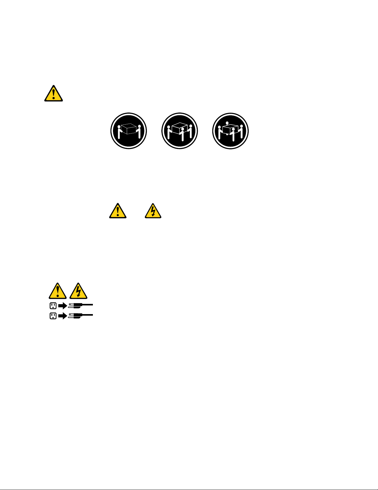
≥18kg(37lbs)≥32kg(70.5lbs)≥55kg(121.2lbs)
PRECAUCIÓN:
Adopteprocedimientossegurosallevantarelequipo.
PRECAUCIÓN:
Elbotóndecontroldealimentacióndeldispositivoyelinterruptordealimentacióndelafuentede
alimentaciónnodesconectanlacorrienteeléctricasuministradaaldispositivo.Además,eldispositivo
podríatenermásdeuncabledealimentación.Parasuprimirtodalacorrienteeléctricadeldispositivo,
asegúresedequetodosloscablesdealimentaciónesténdesconectadosdelatomadecorriente.
Chapter2Safetyinformation27
Page 34

28ThinkCentreHardwareMaintenanceManual
Page 35

Chapter3.Generalinformation
Thischapterprovidesgeneralinformationthatappliestoallmachinetypessupportedbythispublication.
TheThinkVantageProductivityCenterprogram
UsetheThinkVantage®ProductivityCenterprogramforgeneralinformationabouttheuse,operation,and
maintenanceofthecomputer.TheThinkVantageProductivityCenterprogramalsocontainsinformationto
helpsolveproblemsandgetrepairserviceorothertechnicalassistance.TheThinkVantageProductivity
CenterprogramispreinstalledonmostThinkCentreproducts.
Additionalinformationresources
IfyouhaveInternetaccess,themostup-to-dateinformationforyourcomputerisavailablefromtheWorld
WideWeb.
Youcanndthefollowinginformation:
•CRUremovalandinstallationinstructions
•Publications
•T roubleshootinginformation
•Partsinformation
•Downloadsanddrivers
•Linkstootherusefulsourcesofinformation
Toaccessthisinformation,gotohttp://www.lenovo.com/support/.
Specications
Thissectionliststhephysicalspecicationsforyourcomputer.
Formachinetypes:7057,7062,7092,9342,9344,9354,9426,9486,9624,
9707,9787,9804,9945
Thissectionliststhephysicalspecications.
Dimensions
Width:331mm(13in.)
Height:104mm(4.1in.)
Depth:412mm(16.2in.)
Weight
Maximumcongurationasshipped:8.8kg(19.4lbs)
Formachinetypes:7061,7090,9353,9421,9485,9623,9625,9705,9786,
9795,9935,9946,9953
Thissectionliststhephysicalspecications.
©CopyrightLenovo2008,2010
29
Page 36

Dimensions
Width:175mm(6.9in.)
Height:402mm(15.8in.)
Depth:440mm(17.3in.)
Weight
Maximumcongurationasshipped:11kg(24lbs)
Forallmachinetypes
Environment
•Airtemperature:
Operating:10°to35°C(50°to95°F)
Non-operating:-40°to60°C(-40°to140°F)
•Humidity:
Operating:10%to80%(10%perhour,noncondensing)
Non-operating:10%to90%(10%perhour)
•Maximumaltitude:
Operating:-50to10,000ft(-15.2to3048m)
Non-operating:-50to35,000ft(-15.2to10.668)
Electricalinput
•Inputvoltage:
–Lowrange:
Minimum:100Vac
Maximum:127Vac
Inputfrequencyrange:50/60Hz
Voltageswitchsetting:115Vac
–Highrange:
Minimum:200Vac
Maximum:240Vac
Inputfrequencyrange:50/60Hz
Voltageswitchsetting:230Vac
30ThinkCentreHardwareMaintenanceManual
Page 37

Chapter4.GeneralCheckout
Attention
Thedrivesinthecomputeryouareservicingmighthavebeenrearrangedorthedrivestartupsequence
changed.Beextremelycarefulduringwriteoperationssuchascopying,saving,orformatting.Dataor
programscanbeoverwrittenifyouselectanincorrectdrive.
Generalerrormessagesappearifaproblemorconictisfoundbyanapplicationprogram,theoperating
system,orboth.Foranexplanationofthesemessages,refertotheinformationsuppliedwiththatsoftware
package.
BeforereplacinganyFRUs,ensurethatthelatestlevelofBIOSisinstalledonthesystem.Adown-levelBIOS
mightcausefalseerrorsandunnecessaryreplacementofthesystemboard.Formoreinformationonhowto
determineandobtainthelatestlevelBIOS,see"BIOSlevels"onpage467
Usethefollowingproceduretohelpdeterminethecauseoftheproblem:
1.Power-offthecomputerandallexternaldevices.
2.Checkallcablesandpowercords.
3.Setalldisplaycontrolstothemiddleposition.
4.Power-onallexternaldevices.
5.Power-onthecomputer.
•Lookfordisplayederrorcodes
•Listenforbeepcodes
•Lookforreadableinstructionsoramainmenuonthedisplay.
Ifyoudidnotreceivethecorrectresponse,proceedtostep6onpage31
Ifyoudoreceivethecorrectresponse,proceedtostep7onpage31.
6.Lookatthefollowingconditionsandfollowtheinstructions:
.
.
•IfyouhearbeepcodesduringPOST,goto"Beepsymptoms"onpage61
•IfthecomputerdisplaysaPOSTerror,goto"POSTerrorcodes"onpage62.
•Ifthecomputerhangsandnoerrorisdisplayed,continueatstep7onpage31.
7.RuntheDiagnosticprograms.SeeChapter5"Diagnostics"onpage33.
•Ifyoureceiveanerror,replacethepartthatthediagnosticprogramcallsoutorgoto"Diagnostic
errorcodes"onpage44.
•Iftheteststopsandyoucannotcontinue,replacethelastdevicetested.
.
Problemdeterminationtips
Duetothevarietyofhardwareandsoftwarecombinationsthatcanbeencountered,usethefollowing
informationtoassistyouinproblemdetermination.Ifpossible,havethisinformationavailablewhen
requestingassistancefromServiceSupportandEngineeringfunctions.
•Machinetypeandmodel
•Processororharddiskupgrades
•Failuresymptom
–Dodiagnosticsindicateafailure?
–What,when,where,single,ormultiplesystems?
–Isthefailurerepeatable?
©CopyrightLenovo2008,2010
31
Page 38

–Hasthiscongurationeverworked?
–Ifithasbeenworking,whatchangesweremadepriortoitfailing?
–Isthistheoriginalreportedfailure?
•Diagnosticsversion
–T ypeandversionlevel
•Hardwareconguration
–Print(printscreen)congurationcurrentlyinuse
–BIOSlevel
•Operatingsystemsoftware
–T ypeandversionlevel
Notes:Toeliminateconfusion,identicalsystemsareconsideredidenticalonlyifthey:
1.Aretheexactmachinetypeandmodels
2.HavethesameBIOSlevel
3.Havethesameadapters/attachmentsinthesamelocations
4.Havethesameaddressjumpers/terminators/cabling
5.Havethesamesoftwareversionsandlevels
6.HavethesameDiagnosticDiskettes(version)
7.Havethesamecongurationoptionssetinthesystem
8.Havethesamesetupfortheoperatingsystemcontrolles
Comparingthecongurationandsoftwareset-upbetween“workingandnon-working”systemswilloften
leadtoproblemresolution.
32ThinkCentreHardwareMaintenanceManual
Page 39

Chapter5.Diagnostics
Diagnosticprogramsareusedtotesthardwarecomponentsofyourcomputerandreport
operating-system-controlledsettingsthatcancausehardwarefailures.Therearetwodiagnosticprograms
preinstalledonyourcomputer:
•LenovoSystemT oolbox(usedtodiagnoseproblemswhilerunningtheWindowsoperatingsystem)
•PC-DoctorforWindowsPE(usedwhenyourWindowsoperatingsystemdoesnotstart)
Notes:
1.Y oucanalsodownloadthelatestversionoftheLenovoSystemToolboxandPC-DoctorforDOS
diagnosticprogramsfrom:http://www.lenovo.com/support
2.IfyouareunabletoisolateandrepairtheproblemyourselfafteryourunLenovoSystemToolboxand
PC-DoctorforWindowsPE,saveandprinttheloglescreatedbybothdiagnosticprograms.Youwill
needthelogleswhenyouspeaktoaLenovotechnicalsupportrepresentative.(Theloglecreatedby
LenovoSystemToolboxisautomaticallysavedinC:\PCDR\DETAILED.txt.)
LenovoSystemToolbox
LenovoSystemToolboxisadiagnosticprogramthatworksthroughtheWindowsoperatingsystemand
enablesyoutoviewsymptomsandsolutionsforcomputerproblems,accesstheLenovotroubleshooting
center,updatesystemdrivers,andreviewsysteminformation.
TorunLenovoSystemToolbox,clickStart®AllPrograms®LenovoSystemT oolbox®LenovoSystem Toolbox.Followtheinstructionsonthescreen.Foradditionalinformationaboutrunningthediagnostic program,refertotheLenovoSystemToolboxhelpsystem.
IfyoustillsuspectaproblemafterLenovoSystemToolboxrunssuccessfully,runPC-DoctorforWindows
PEtohelpyoudiagnosethecomputerproblem.
LenovoSystemToolboxalsohasproblemdeterminationaidsthatdeterminesoftwareandusageproblems.
PC-DoctorforWindowsPE
ThePC-DoctorforWindowsPEdiagnosticprogramispartoftheRescueandRecovery®workspaceon
eachLenovocomputer.UsePC-DoctorforWindowsPE,ifyouareunabletostarttheWindowsoperating
systemorifPC-DoctorforWindowshasnotbeensuccessfulinisolatingapossibleproblem.
RunningdiagnosticsfromtheRescueandRecoveryworkspace
YoucanrunthePC-DoctorforWindowsPEdiagnosticprogramfromtheRescueandRecoveryworkspace.
TorundiagnosticsfromtheRescueandRecoveryworkspace,usethefollowingprocedure:
1.Shutdowntheoperatingsystemandturnoffthecomputer.
2.RepeatedlypressandreleasetheF11keyasyouturnonthecomputer.
3.Whenyouhearbeepsorseealogoscreen,stoppressingtheF11key.TheRescueandRecovery
workspaceopens.
4.FromtheRescueandRecoveryworkspace,selectDiagnosehardware.
5.Thediagnosticprogramopensautomatically.Selectthediagnostictestyouwanttorun.PresstheF1
keyforadditionalhelp.
©CopyrightLenovo2008,2010
33
Page 40

6.Followtheinstructionsonthescreen.
Note:RescuemediaincludesPC-DoctorforWindowsPE.Formoreinformationaboutrescuemedia,
seetheUserGuideforthecomputer.
PC-DoctorforDOS
UsePC-DoctorforDOS,ifyouareunabletostarttheWindowsoperatingsystemorifPC-Doctorfor
Windowshasnotbeensuccessfulinisolatingapossibleproblem.YoucanrunPC-DoctorforDOSfroma
diagnosticCDimageordiagnosticdiskettesthathavebeencreated.
Note:ItisimportanttocreateadiagnosticCDimageordiagnosticdiskettesincasePC-DoctorforWindows
PEcannotberunfromtheRescueandRecoveryworkspace.
CreatingadiagnosticCDimage
TocreateadiagnosticCDimage,downloadaself-startingbootableCDimage(knownasan.isoimage)
ofthediagnosticprogramfromhttp://www.lenovo.com/support/.Afteryoudownloadtheimage,you
cancreatetheCDusinganyCDburningsoftware.
IfthecomputerdoesnothaveaCDburneroryoudonothaveInternetaccess,see"Creatingdiagnostic
diskettes"onpage34.
Creatingdiagnosticdiskettes
Tocreatediagnosticdiskettes,downloadthePC-DoctorforDOSdiagnosticprogramfrom
http://www.lenovo.com/support/ontotwoblank,formatteddiskettes.
IfyoudonothaveInternetaccess,createthediagnosticdiskettesusingthefollowingprocedure:
Note:Y ouwillneedadiskettedriveonthecomputeroraUSBdiskettedrivetocompletethisprocedure.
1.Shutdowntheoperatingsystemandturnoffthecomputer.
2.IfyouareusingaUSBdiskettedrive,plugitintothecomputer.
3.RepeatedlypressandreleasetheF11keyasyouturnonthecomputer.
4.Whenyouhearbeepsorseealogoscreen,stoppressingtheF11key.TheRescueandRecovery
workspaceopens.
Note:Forsomemodels,presstheEsckeytoenterRescueandRecovery.
5.FromtheRescueandRecoveryworkspace,selectCreatediagnosticdisks.
6.Followtheinstructionsonthescreen.
7.Whenprompted,insertablank,formatteddisketteintothediskettedriveandcontinuetofollowthe
instructionsonthescreen.
8.Whentheoperationiscomplete,removethedisketteandclickQuit.
9.Insertanotherblank,formatteddisketteintothediskettedriveandcontinuetofollowtheinstructionson
thescreen.
10.Whentheoperationiscomplete,removethedisketteandclickQuit.
RunningdiagnosticsfromtheCDordiskettes
TorundiagnosticsfromthediagnosticCDimageordiagnosticdiskettesthatyoucreated,usethefollowing
procedure:
1.Makesurethecomputeristurnedoff.
2.IfyouarerunningdiagnosticsfromdiskettesusingaUSBdiskettedrive,plugintheUSBdevice.
34ThinkCentreHardwareMaintenanceManual
Page 41

3.InserttheCDintotheopticaldriveortherstdiagnosticdisketteintothediskettedrive.
4.Restartthecomputer.
Note:Ifthediagnosticprogramdoesnotstart,youmightnothaveyouropticaldriveordiskettedriveset
asastartabledevice.See"Selectingastartupdevice"onpage41forinstructionsonhowtochange
thestartupdevice.
5.Whenthediagnosticsprogramopens,followtheinstructionsonthescreen.
Note:Ifyouarerunningdiagnosticsfromadiskette,whenprompted,removetherstdisketteand
inserttheseconddiskette.
6.Whentheprogramnishes,besuretoremovetheCDordiskettefromthedrive.
7.Selectthediagnostictestyouwanttorun.PresstheF1keyforadditionalhelp.
Navigatingthroughthediagnosticsprograms
Usethecursormovementkeystonavigatewithinthemenus.
•TheEnterkeyisusedtoselectamenuitem.
•TheEsckeyisusedtobackuptothepreviousmenu.
•ForonlinehelpselectF1.
Runningtests
Therearefourwaystorunthediagnostictests.
•Usingthecursormovementkeys,highlightRunNormalTestorRunQuickT estfromtheDiagnostics
menuandthenpressEnter.Thisautomaticallyrunsapre-denedgroupoftestsfromeachtestcategory.
RunNormalTestrunsamoreextensivesetofteststhandoesRunQuickT estandtakeslongerto
complete.
•PressF5toautomaticallyrunallselectedtestsinallcategories.
•Fromwithinatestcategory,pressCtrl-Entertoautomaticallyrunonlytheselectedtestsinthatcategory.
•Usingthecursormovementkeys,highlightasingletestwithinatestcategory,andthenpressEnter.
Thisrunsonlythattest.
PressEscatanytimetostopthetestingprocess.
Testresults(N/A,PASSED,FAILED,ABORTED)aredisplayedintheeldbesidethetestdescriptionandin
thetestlog.See"Viewingthetestlog"onpage36.
Toselectoneormoretests,usethefollowingprocedure.
1.Openthecorrespondingtestcategory.
2.Usingthecursormovementkeys,highlightthedesiredtest.
3.Pressthespacebar.
Aselectedtestismarkedby>>.Pressingthespacebaragainde-selectsatestandremovesthe>>.
4.Repeatsteps2and3abovetoselectalldesiredtests.
Testresults
Diagnosticstestresultsproducethefollowingerrorcodeformat:
FunctionCode
FailureT ypeDeviceIDDate
ChkDigits
Text
Chapter5Diagnostics35
Page 42

•FunctionCode:
RepresentsthefeatureorfunctionwithinthePC.
•FailureType:
Representsthetypeoferrorencountered.
•DeviceID:
Containsthecomponent'sunit-IDwhichcorrespondstoeitheraxeddiskdrive,removablemediadrive,
serialorparallelport,processor,specicRIMM,oradeviceonthePCIbus.
•Date:
Containsthedatewhenthediagnostictestwasrun.ThedateisretrievedfromCMOSanddisplayed
usingtheYYYYMMDDformat.
•ChkDigits:
Containsa2-digitcheck-digitvaluetoensurethefollowing:
–Diagnosticswererunonthespecieddate.
–Diagnosticswererunonthespeciedcomputer.
–Thediagnosticerrorcodeisrecordedcorrectly.
•T ext:
Descriptionoftheerror.
Note:See"Diagnosticerrorcodes"onpage44
forerrorcodelistings.
QuickandFullerase-harddrive
Thediagnosticsprogramofferstwoharddriveformatutilities:
•QuickEraseHardDrive
•FullEraseHardDrive
TheQuickEraseHardDriveprovidesaDOSutilitythatperformsthefollowing:
•DestroystheMasterBootRecord(MBR)ontheharddrive.
•DestroysallcopiesoftheFATT ableonallpartitions(boththemasterandbackup).
•Destroysthepartitiontable.
•Providesmessagesthatwarntheuserthatthisisanon-recoverableprocess.
TheFullEraseHardDriveprovidesaDOSutilitythatperformsthefollowing:
•PerformsallthestepsinQuickErase.
•ProvidesaDOSutilitythatwritesrandomdatatoallsectorsoftheharddrive.
•Providesanestimateoftimetocompletionalongwithavisualrepresentationofcompletionstatus.
•Providesmessagesthatwarntheuseraboutnon-recoverableprocess.
Important:MakesurethatalldataisbackedupbeforeusingtheQuickorFullErasefunctions.
ToselecttheQuickEraseorFullEraseHardDriveutility,usethefollowingprocedure:
1.SelecttheUTILITYoptiononthetoolbarandpressEnter.
2.SelecteithertheQUICKERASEorFULLERASEHARDDISKoptionandfollowtheinstructions.
Viewingthetestlog
Errorsreportedbythediagnostictestwillbedisplayedbytheprogramasafailedtest.
36ThinkCentreHardwareMaintenanceManual
Page 43

Toviewdetailsofafailureortoviewalistoftestresults,usethefollowingprocedurefromanytestcategory
screen:
1.PressF3toactivatethelogle.
2.PressF3againtosavetheletodisketteorpressF2toprintthele.
Chapter5Diagnostics37
Page 44

38ThinkCentreHardwareMaintenanceManual
Page 45

Chapter6.UsingtheSetupUtility
TheSetupUtilityprogramisusedtoviewandchangethecongurationsettingsofyourcomputer,regardless
ofwhichoperatingsystemyouareusing.However,theoperating-systemsettingsmightoverrideanysimilar
settingsintheSetupUtilityprogram.
StartingtheSetupUtilityprogram
TostarttheSetupUtilityprogram,dothefollowing:
1.Ifyourcomputerisalreadyonwhenyoustartthisprocedure,shutdowntheoperatingsystemand
turnoffthecomputer.
2.PressandholdtheF1keythenturnonthecomputer.
3.ReleasetheF1key.
Notes:
a.IfyouareusingaUSBkeyboardandtheSetupUtilityprogramdoesnotdisplayusingthismethod,
repeatedlypressandreleasetheF1keyratherthanleavingitpressedwhenturningonthecomputer.
b.Ifauserpasswordoranadministratorpasswordhasbeenset,theSetupUtilityprogrammenuisnot
displayeduntilyoutypeyourpassword.Formoreinformation,see"Usingpasswords"onpage39.
TheSetupUtilitymightstartautomaticallywhenPOSTdetectsthathardwarehasbeenremovedornew
hardwarehasbeeninstalledinyourcomputer.
Viewingandchangingsettings
TheSetupUtilityprogrammenulistsitemsthatidentifysystemcongurationtopics.Tovieworchange
settings,see"StartingtheSetupUtilityprogram"onpage39
WhenworkingwiththeSetupUtilityprogrammenu,youmustusethekeyboard.Thekeysusedtoperform
varioustasksaredisplayedatthebottomofeachscreen.
.
Usingpasswords
ByusingtheSetupUtilityprogram,youcansetpasswordstopreventunauthorizedpersonsfromgaining
accesstoyourcomputeranddata.See"StartingtheSetupUtilityprogram"onpage39.Thefollowing
typesofpasswordsareavailable:
•UserPassword
•AdministratorPassword
Youdonothavetosetanypasswordstouseyourcomputer.However,ifyoudecidetosetanypasswords,
readthefollowingsections.
Passwordconsiderations
Apasswordcanbeanycombinationofuptotwelvealphabeticandnumericcharacters(a-zand0-9).For
securityreasons,itisagoodideatouseastrongpasswordthatcannotbeeasilycompromised.Passwords
shouldadheretothefollowingrules:
•Haveatleasteightcharactersinlength
©CopyrightLenovo2008,2010
39
Page 46

•Containatleastonealphabeticcharacterandonenumericcharacter
•SetupUtilityprogramandharddiskdrivepasswordsarenotcasesensitive
•Notbeyournameoryourusername
•Notbeacommonwordoracommonname
•Besignicantlydifferentfromyourpreviouspassword
UserPassword
WhenaUserPasswordisset,thecomputercannotbeuseduntilavalidpasswordistypedfromthe
keyboard.
AdministratorPassword
WhenanAdministratorPasswordisset,itdetersunauthorizedpersonsfromchangingconguration
settings.Ifyouareresponsibleformaintainingthesettingsofseveralcomputers,youmightwanttosetan
AdministratorPassword.
AfteryousetanAdministratorPassword,apasswordpromptisdisplayedeachtimeyoutrytoaccessthe
SetupUtilityprogram.
Ifboththeuserandadministratorpasswordsareset,youcantypeeitherpassword.However,tochange
anycongurationsettings,youmustuseyouradministratorpassword.
Setting,changing,anddeletingapassword
Toset,change,ordeleteapassword,dothefollowing:
Note:Apasswordcanbeanycombinationofuptotwelvealphabeticandnumericcharacters(a-zand0-9).
Formoreinformation,see"Passwordconsiderations"onpage39
1.StarttheSetupUtilityprogram(seeChapter6"UsingtheSetupUtility"onpage39).
2.FromtheSetupUtilityprogrammenu,selectSecurity.
3.Basedonyourneed,selectSetUserPasswordsorSetAdministratorPasswords.
4.Readtheinformationdisplayedontherightsideofthescreen.
.
Enablingordisablingadevice
Youcanenableordisableuseraccesstoadevice.
SATA1WhenthisfeatureissettoDisable,alldevicesconnectedtotheSATAcontroller(such
asharddiskdrivesortheCD-ROMdrive)aredisabledandwillnotbedisplayedin
thesystemconguration.
OnBoardFloppyController
TosettheSATA1,dothefollowing:
1.StarttheSetupUtilityprogram(see"StartingtheSetupUtilityprogram"onpage39).
2.FromtheSetupUtilityprogrammenu,selectDevices®SATADrivesSetup®SATA1andpressEnter.
3.Select32BitDataT ransfer.
4.SelectthedesiredsettingsandpressEnter.
5.ReturntotheSetupUtilityprogrammenuandselectExit®SaveChangesandExit.
WhenthisfeatureissettoDisable,thediskettedrivecannotbeaccessed.
Note:Ifyoudonotwanttosavethesettings,selectDiscardChangesorDiscardChangesandExit.
40ThinkCentreHardwareMaintenanceManual
Page 47

TosettheOnBoardFloppyController,dothefollowing:
1.StarttheSetupUtilityprogram(see"StartingtheSetupUtilityprogram"onpage39).
2.FromtheSetupUtilityprogrammenu,selectDevices®FloppyDriveSetup®OnBoardFloppy
Controller.
3.SelectthedesiredsettingsandpressEnter.
4.ReturntotheSetupUtilityprogrammenuandselectExit®SaveChangesandExit.
Note:Ifyoudonotwanttosavethesettings,selectDiscardChangesorDiscardChangesandExit.
Selectingastartupdevice
IfyourcomputerdoesnotstartupfromadevicesuchastheCD-ROM,diskette,orharddiskdriveas
expected,useoneofthefollowingprocedurestoselectastartupdevice.
Selectingatemporarystartupdevice
Usethisproceduretostartupfromanystartdevice.
Note:NotallCDs,harddiskdrives,anddiskettesarebootable.
1.T urnoffyourcomputer.
2.PressandholdtheF12keythenturnonthecomputer.WhentheStartupDeviceMenuappears,release
theF12key.
Note:IfyouareusingaUSBkeyboardandtheStartupDeviceMenudoesnotdisplayusingthismethod,
repeatedlypressandreleasetheF12keyratherthanleavingitpressedwhenturningonthecomputer.
3.SelectthedesiredstartupdevicefromtheStartupDeviceMenuandpressEntertobegin.
Note:SelectingastartupdevicefromtheStartupDevicemenudoesnotpermanentlychangethestartup
sequence.
Selectingorchangingthestartupdevicesequence
Tovieworpermanentlychangetheconguredstartupdevicesequence,dothefollowing:
1.StarttheSetupUtilityprogram(see"StartingtheSetupUtilityprogram"onpage39).
2.SelectStartupandreadtheinformationdisplayedontherightsideofthescreen.
3.SelectthedevicesforthePrimaryBootSequence,theAutomaticBootSequence,andtheErrorBoot
Sequence.
4.FromtheSetupUtilitymenu,selectExit®SaveChangesandExit.
Ifyouhavechangedthesesettingsandwanttoreturntothedefaultsettings,selectLoadOptimalDefaults
ontheExitmenu.
ExitingfromtheSetupUtilityprogram
Afteryounishviewingorchangingsettings,pressEsctoreturntotheSetupUtilityprogrammenu(you
mighthavetopressEscseveraltimes).Ifyouwanttosavethenewsettings,selectSaveChangesand
Exit.Otherwise,yourchangeswillnotbesaved.
Chapter6UsingtheSetupUtility41
Page 48

42ThinkCentreHardwareMaintenanceManual
Page 49
Chapter7.Symptom-to-FRUIndex
TheSymptom-to-FRUindexlistserrorsymptomsandpossiblecauses.Themostlikelycauseislistedrst.
AlwaysbeginwithChapter4"GeneralCheckout"onpage31
decidewhichFRUstohaveavailablewhenservicingacomputer.Ifyouareunabletocorrecttheproblem
usingthisindex,goto"Undeterminedproblems"onpage65.
Notes:
•Ifyouhavebothanerrormessageandanincorrectaudioresponse,diagnosetheerrormessagerst.
•Ifyoucannotrunthediagnostictestsoryougetadiagnosticerrorcodewhenrunningatest,butdidreceivea
POSTerrormessage,diagnosethePOSTerrormessagerst.
•Ifyoudidnotreceiveanyerrormessage,lookforadescriptionofyourerrorsymptomsintherstpartofthisindex.
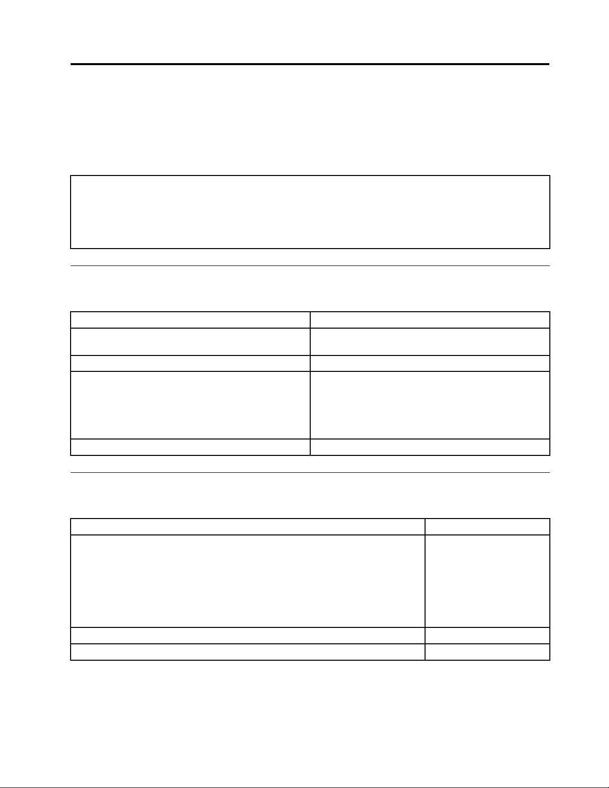
Harddiskdrivebooterror
Aharddiskdrivebooterror(errorcodes1962andI999030X)canhavethefollowingcauses.
ErrorFRU/Action
Thestart-updriveisnotinthebootsequencein
conguration.
Nooperatingsysteminstalledonthebootdrive.Installanoperatingsystemonthebootdrive.
Thebootsectoronthestart-updriveiscorrupted.
Thedriveisdefective.
.Thisindexcanalsobeusedtohelpyou
Checkthecongurationandensurethestart-updriveis
inthebootsequence.
Thedrivemustbeformatted,dothefollowing:
1.Attempttoback-upthedataonthefailingharddisk
drive.
2.Usingtheoperatingsystemsprograms,formatthe
harddiskdrive.
Replacetheharddiskdrive.
PowerSupplyProblems
Ifyoususpectapowerproblem,usethefollowingprocedures.
Check/VerifyFRU/Action
Checkthefollowingforproperinstallation.
•PowerCord
•On/OffSwitchconnector
•On/OffSwitchPowerSupplyconnector
•SystemBoardPowerSupplyconnectors
•Microprocessor(s)connection
Checkthepowercordforcontinuity.PowerCord
Checkthepower-onswitchforcontinuity.Power-onSwitch
©CopyrightLenovo2008,2010
Reseatconnectors
43
Page 50
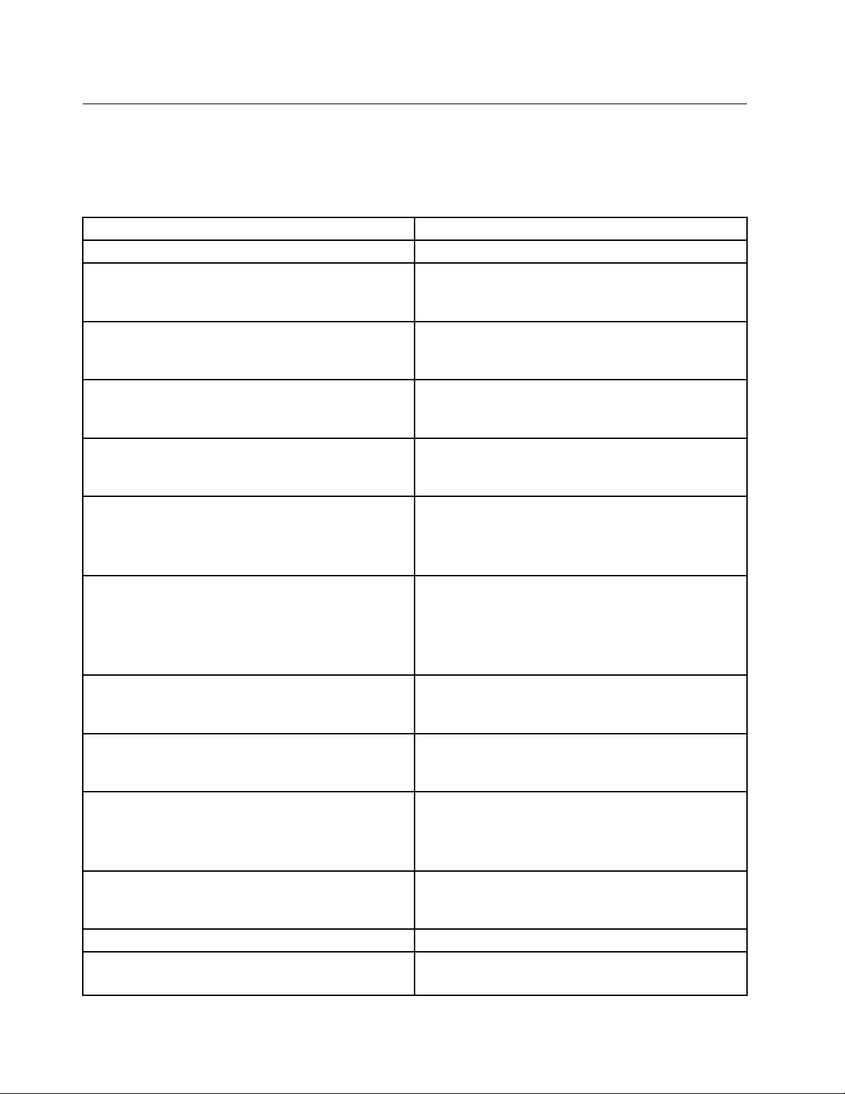
Diagnosticerrorcodes
Refertothefollowingdiagnosticerrorcodeswhenusingthediagnostictests.See"Runningtests"on
page35forthespecictypeforinformationabouttheDiagnosticprograms.
Inthefollowingindex,Xcanrepresentanynumber.
DiagnosticErrorCodeFRU/Action
000-000-XXXBIOSTestPassed
000-002-XXXBIOSTimeout1.Flashthesystem.See"Flashupdateprocedures"
000-024-XXXBIOSAddressingtestfailure1.Flashthesystem.See"Flashupdateprocedures"
000-025-XXXBIOSChecksumValueerror1.Flashthesystem.See"Flashupdateprocedures"
000-026-XXXFLASHdataerror1.Flashthesystem.See"Flashupdateprocedures"
000-027-XXXBIOSConguration/Setuperror1.RunSetup
000-034-XXXBIOSBufferAllocationfailure
000-035-XXXBIOSResetConditiondetected1.Flashthesystem.See"Flashupdateprocedures"
000-036-XXXBIOSRegistererror1.Flashthesystem.See"Flashupdateprocedures"
000-038-XXXBIOSExtensionfailure1.Flashthesystem.See"Flashupdateprocedures"
000-039-XXXBIOSDMIdataerror1.Flashthesystem.See"Flashupdateprocedures"
000-195-XXXBIOSTestabortedbyuser
000-196-XXXBIOStesthalt,errorthresholdexceeded
Noaction
onpage467
2.Systemboard
onpage467
2.Systemboard
onpage467
2.Systemboard
onpage467
2.Systemboard
2.Flashthesystem.See"Flashupdateprocedures"on
page467
3.Systemboard
1.Rebootthesystem
2.Flashthesystem.See"Flashupdateprocedures"on
page467
3.Runmemorytest
4.Systemboard
onpage467
2.Systemboard
onpage467
2.Systemboard
onpage467
2.PCIadaptercard
3.Systemboard
onpage467
2.Systemboard
InformationonlyRe-startthetest,ifnecessary
1.PressF3toreviewthelogle
2.Re-startthetesttoresetthelogle
44ThinkCentreHardwareMaintenanceManual
Page 51
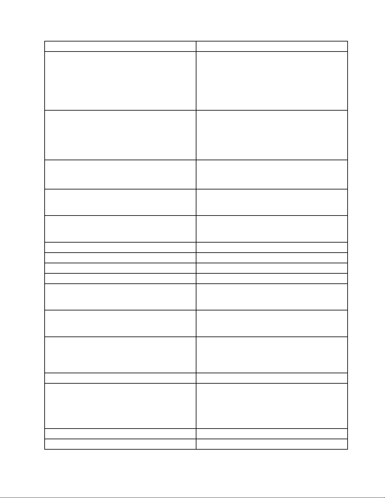
DiagnosticErrorCodeFRU/Action
000-197-XXXBIOStestwarning
1.Makesurethecomponentthatiscalledoutis
connectedand/orenabled.SeeChapter6"Using
theSetupUtility"onpage39
2.Re-runtest
3.Replacethecomponentthatiscalledoutinwarning
statement
4.Replacethecomponentundertest
000-198-XXXBIOStestaborted
1.Makesurethecomponentthatiscalledoutis
connectedand/orenabled.SeeChapter6"Using
theSetupUtility"onpage39
2.Flashthesystemandretest.See"Flashupdate
procedures"onpage467
3.Goto"Undeterminedproblems"onpage65
000-199-XXXBIOStestfailed,causeunknown1.Goto"Undeterminedproblems"onpage65
2.Flashthesystemandre-test
3.Replacecomponentunderfunctiontest
000-250-XXXBIOSAPMfailure1.Flashthesystem.See"Flashupdateprocedures"
onpage467
2.Systemboard
000-270-XXXBIOSACPIfailure1.Flashthesystem.See"Flashupdateprocedures"
onpage467
2.Systemboard
001-000-XXXSystemTestPassed
Noaction
001-00X-XXXSystemErrorSystemboard
001-01X-XXXSystemErrorSystemboard
001-024-XXXSystemAddressingtestfailureSystemboard
001-025-XXXSystemChecksumValueerror1.Flashthesystem.See"Flashupdateprocedures"
onpage467
2.Systemboard
001-026-XXXSystemFLASHdataerror1.Flashthesystem.See"Flashupdateprocedures"
onpage467
2.Systemboard
001-027-XXXSystemConguration/Setuperror1.RunSetup
2.Flashthesystem.See"Flashupdateprocedures"on
page467
3.Systemboard
001-032-XXXSystemDeviceControllerfailureSystemboard
001-034-XXXSystemDeviceBufferAllocationfailure
1.Rebootthesystem
2.Flashthesystem.See"Flashupdateprocedures"on
page467
3.Runmemorytest
4.Systemboard
001-035-XXXSystemDeviceResetconditiondetectedSystemboard
001-036-XXXSystemRegistererrorSystemboard
Chapter7Symptom-to-FRUIndex45
Page 52
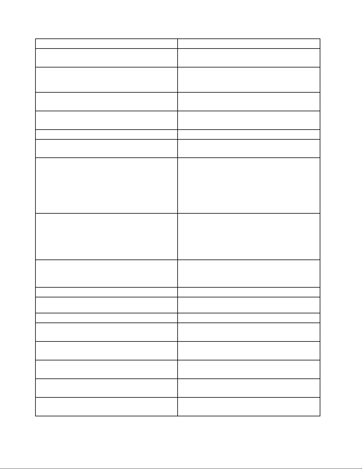
DiagnosticErrorCodeFRU/Action
001-038-XXXSystemExtensionfailure1.PCIadaptercard
2.Systemboard
001-039-XXXSystemDMIdatastructureerror1.Flashthesystem.See"Flashupdateprocedures"
onpage467
2.Systemboard
001-040-XXXSystemIRQfailure1.Power-off/onsystemandre-test
2.Systemboard
001-041-XXXSystemDMAfailure1.Power-off/onsystemandre-test
2.Systemboard
001-195-XXXSystemTestabortedbyuser
001-196-XXXSystemtesthalt,errorthresholdexceeded
001-197-XXXSystemtestwarning
001-198-XXXSystemtestaborted
001-199-XXXSystemtestfailed,causeunknown1.Goto"Undeterminedproblems"onpage65
001-250-XXXSystemECCerrorSystemboard
001-254-XXX001-255-XXX001-256-XXX001-257-XXX
SystemDMAerror
001-260-XXX001-264-XXXSystemIRQerrorSystemboard
001-268-XXXSystemIRQ1failure1.DeviceonIRQ1
001-269-XXXSystemIRQ2failure1.DeviceonIRQ2
001-270-XXXSystemIRQ3failure1.DeviceonIRQ3
001-271-XXXSystemIRQ4failure1.DeviceonIRQ4
001-272-XXXSystemIRQ5failure1.DeviceonIRQ5
InformationonlyRe-startthetest,ifnecessary
1.PressF3toreviewthelogle
2.Re-startthetesttoresetthelogle
1.Makesurethecomponentthatiscalledoutis
connectedand/orenabled.SeeChapter6"Using
theSetupUtility"onpage39
2.Re-runtest
3.Replacethecomponentthatiscalledoutinwarning
statement
4.Replacethecomponentundertest
1.Ifacomponentiscalledout,makesureitis
connectedand/orenabled.SeeChapter6"Using
theSetupUtility"onpage39
2.Flashthesystemandretest.See"Flashupdate
procedures"onpage467
3.Goto"Undeterminedproblems"onpage65
2.Flashthesystemandre-test
3.Replacecomponentunderfunctiontest
Systemboard
2.Systemboard
2.Systemboard
2.Systemboard
2.Systemboard
2.Systemboard
46ThinkCentreHardwareMaintenanceManual
Page 53

DiagnosticErrorCodeFRU/Action
001-273-XXXSystemIRQ6(diskettedrive)failure1.DisketteCable
2.Diskettedrive
3.Systemboard
001-274-XXXSystemIRQ7failure1.DeviceonIRQ7
2.Systemboard
001-275-XXXSystemIRQ8failure1.DeviceonIRQ8
2.Systemboard
001-276-XXXSystemIRQ9failure1.DeviceonIRQ9
2.Systemboard
001-277-XXXSystemIRQ10failure1.DeviceonIRQ10
2.Systemboard
001-278-XXXSystemIRQ11failure1.DeviceonIRQ11
2.Systemboard
001-279-XXXSystemIRQ12failure1.DeviceonIRQ12
2.Systemboard
001-280-XXXSystemIRQ13failure1.DeviceonIRQ13
2.Systemboard
001-281-XXXSystemIRQ14(harddiskdrive)failure
1.Harddiskdrivecable
2.Harddiskdrive
3.Systemboard
001-282-XXXSystemIRQ15failure1.DeviceonIRQ15
2.Systemboard
001-286-XXX001-287-XXX001-288-XXXSystemTimer
Systemboard
failure
001-292-XXXSystemCMOSRAMerror1.RunSetupandre-test
2.Systemboard
001-293-XXXSystemCMOSBattery1.CMOSBattery
2.Systemboard
001-298-XXXSystemRTCdate/timeupdatefailure1.Flashthesystem.See"Flashupdateprocedures"
onpage467
2.Systemboard
001-299-XXXSystemRTCperiodicinterruptfailureSystemboard
001-300-XXXSystemRTCAlarmfailureSystemboard
001-301-XXXSystemRTCCenturybyteerror1.Flashthesystem.See"Flashupdateprocedures"
onpage467
2.Systemboard
005-000-XXXVideoT estPassedNoaction
005-00X-XXXVideoerror1.Videocard,ifinstalled
2.Systemboard
005-010-XXX005-011-XXX005-012-XXX005-013-XXX
VideoSignalfailure
1.Videocard,ifinstalled
2.Systemboard
Chapter7Symptom-to-FRUIndex47
Page 54
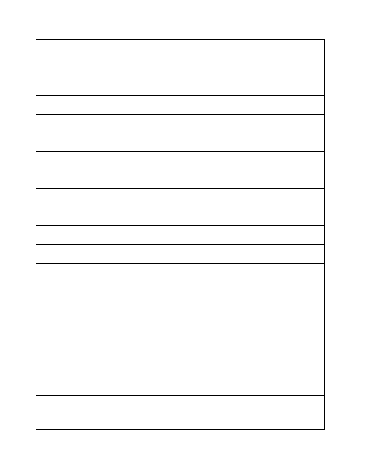
DiagnosticErrorCodeFRU/Action
005-016-XXXVideoSimplePatterntestfailure
005-024-XXXVideoAddressingtestfailure
005-025-XXXVideoChecksumValueerror
005-027-XXXVideoConguration/Setuperror1.RunSetup
005-031-XXXVideoDeviceCablefailure
005-032-XXXVideoDeviceControllerfailure
005-036-XXXVideoRegistererror1.Videocard,ifinstalled
005-038-XXXSystemBIOSextensionfailure
005-040-XXXVideoIRQfailure
005-195-XXXVideoTestabortedbyuser
005-196-XXXVideotesthalt,errorthresholdexceeded1.PressF3toreviewthelogle
005-197-XXXVideotestwarning1.Makesurethecomponentthatiscalledoutis
005-198-XXXVideotestaborted1.Ifacomponentiscalledout,makesureitis
005-199-XXXVideotestfailed,causeunknown
1.VideoRam
2.Videocard,ifinstalled
3.Systemboard
1.Videocard,ifinstalled
2.Systemboard
1.Videocard,ifinstalled
2.Systemboard
2.Videodriversupdate
3.Videocard,ifinstalled
4.Systemboard
1.Videocable
2.Monitor
3.Videocard,ifinstalled
4.Systemboard
1.Videocard,ifinstalled
2.Systemboard
2.Systemboard
1.Videocard,ifinstalled
2.Systemboard
1.Videocard,ifinstalled
2.Systemboard
InformationonlyRe-startthetest,ifnecessary
2.Re-startthetesttoresetthelogle
connectedand/orenabled.SeeChapter6"Using
theSetupUtility"onpage39
2.Re-runtest
3.Replacethecomponentcalledoutinwarning
statement
4.Replacethecomponentundertest
connectedand/orenabled.SeeChapter6"Using
theSetupUtility"onpage39
2.Flashthesystemandre-test.See"Flashupdate
procedures"onpage467
3.Goto"Undeterminedproblems"onpage65
1.Goto"Undeterminedproblems"onpage65
2.Flashthesystemandre-test.See"Flashupdate
procedures"onpage467
3.Replacecomponentunderfunctiontest
48ThinkCentreHardwareMaintenanceManual
Page 55
DiagnosticErrorCodeFRU/Action
005-2XX-XXX005-3XX-XXXVideosubsystemerror1.Videocard,ifinstalled
2.Systemboard
006-000-XXXDisketteinterfaceT estPassed
006-0XX-XXXDisketteinterfaceerror
Noaction
1.DiskettedriveCable
2.Diskettedrive
3.Systemboard
006-195-XXXDisketteinterfaceTestabortedbyuserInformationonlyRe-startthetest,ifnecessary
006-196-XXXDisketteinterfacetesthalt,errorthreshold
exceeded
006-197-XXXDisketteinterfacetestwarning
1.PressF3toreviewthelogle
2.Re-startthetesttoresetthelogle
1.Ifacomponentiscalledout,makesureitis
connectedand/orenabled
2.Re-runtest
3.Replacethecomponentthatiscalledoutinwarning
statement
4.Replacethecomponentundertest
006-198-XXXDisketteinterfacetestaborted
1.Ifacomponentiscalledout,makesureitis
connectedand/orenabled
2.Flashthesystemandre-test.See"Flashupdate
procedures"onpage467
3.Goto"Undeterminedproblems"onpage65
006-199-XXXDisketteinterfacetestfailed,cause
unknown
1.Goto"Undeterminedproblems"onpage65
2.Flashthesystemandre-test
3.Replacecomponentunderfunctiontest
006-25X-XXXDisketteinterfaceError
1.Diskettedrivecable
2.Diskettedrive
3.Systemboard
011-000-XXXSerialportInterfaceT estPassed
011-001-XXXSerialportPresence
Noaction
1.Removeexternalserialdevice,ifpresent
2.Runsetup,enableport
3.Systemboard
011-002-XXX011-003-XXXSerialportTimeout/Parity
Systemboard
error
011-013-XXX011-014-XXXSerialportControl
Systemboard
Signal/Loopbacktestfailure
011-015-XXXSerialportExternalLoopbackfailure
1.Wrapplug
2.Systemboard
011-027-XXXSerialportConguration/Setuperror1.RunSetup,enableport
2.Flashthesystem.See"Flashupdateprocedures"on
page467
3.Systemboard
011-03X-XXX011-04X-XXXSerialportfailureSystemboard
011-195-XXXSerialportTestabortedbyuser
InformationonlyRe-startthetest,ifnecessary
Chapter7Symptom-to-FRUIndex49
Page 56
DiagnosticErrorCodeFRU/Action
011-196-XXXSerialporttesthalt,errorthreshold
exceeded
011-197-XXXSerialporttestwarning
011-198-XXXSerialporttestaborted
011-199-XXXSerialporttestfailed,causeunknown1.Goto"Undeterminedproblems"onpage65
011-2XX-XXXSerialportsignalfailure
014-000-XXXParallelportInterfaceTestPassed
014-001-XXXParallelportPresence1.Removeexternalparalleldevice,ifpresent
014-002-XXX014-003-XXXParallelportTimeout/Parity
error
014-013-XXX014-014-XXXParallelportControl
Signal/Loopbacktestfailure
014-015-XXXParallelportExternalLoopbackfailure
014-027-XXXParallelportConguration/Setuperror1.RunSetup,enableport
014-03X-XXX014-04X-XXXParallelportfailure
014-195-XXXParallelportT estabortedbyuser
014-196-XXXParallelporttesthalt,errorthreshold
exceeded
1.PressF3toreviewthelogle
2.Re-startthetesttoresetthelogle
1.Makesurethecomponentthatiscalledoutis
connectedand/orenabled.SeeChapter6"Using
theSetupUtility"onpage39
2.Re-runtest
3.Replacethecomponentthatiscalledoutinwarning
statement
4.Replacethecomponentundertest
1.Ifacomponentiscalledout,makesureitis
connectedand/orenabled.SeeChapter6"Using
theSetupUtility"onpage39
2.Flashthesystemandre-test.See"Flashupdate
procedures"onpage467
3.Goto"Undeterminedproblems"onpage65
2.Flashthesystemandre-test.See"Flashupdate
procedures"onpage467
3.Replacecomponentunderfunctiontest
1.Externalserialdevice
2.Systemboard
Noaction
2.Runsetup,enableport
3.Systemboard
Systemboard
Systemboard
1.Wrapplug
2.Systemboard
2.Flashthesystem.See"Flashupdateprocedures"on
page467
3.Systemboard
Systemboard
InformationonlyRe-startthetest,ifnecessary
1.PressF3toreviewthelogle
2.Re-startthetesttoresetthelogle
50ThinkCentreHardwareMaintenanceManual
Page 57
DiagnosticErrorCodeFRU/Action
014-197-XXXParallelporttestwarning1.Makesurethecomponentthatiscalledoutis
connectedand/orenabled.SeeChapter6"Using
theSetupUtility"onpage39
2.Re-runtest
3.Replacethecomponentthatiscalledoutinwarning
statement
4.Replacethecomponentundertest
014-198-XXXParallelporttestaborted1.Ifacomponentiscalledout,makesureitis
connectedand/orenabled
2.Flashthesystemandre-test.See"Flashupdate
procedures"onpage467
3.Goto"Undeterminedproblems"onpage65
014-199-XXXParallelporttestfailed,causeunknown
1.Goto"Undeterminedproblems"onpage65
2.Flashthesystemandre-test.See"Flashupdate
procedures"onpage467
3.Replacecomponentunderfunctiontest
014-2XX-XXX014-3XX-XXXParallelportfailure
1.Externalparalleldevice
2.Systemboard
015-000-XXXUSBportInterfaceT estPassed
Noaction
015-001-XXXUSBportPresence1.RemoveUSBdevice(s)andre-test
2.Systemboard
015-002-XXXUSBportTimeout1.RemoveUSBdevice(s)andre-test
2.Systemboard
015-015-XXXUSBportExternalLoopbackfailure1.RemoveUSBdevice(s)andre-test
2.Systemboard
015-027-XXXUSBportConguration/Setuperror1.Flashthesystem.See"Flashupdateprocedures"
onpage467
2.Systemboard
015-032-XXXUSBportDeviceControllerfailureSystemboard
015-034-XXXUSBportbufferallocationfailure
1.Rebootthesystem
2.Flashthesystemandre-test.See"Flashupdate
procedures"onpage467
3.Runmemorytest
4.Systemboard
015-035-XXXUSBportResetconditiondetected1.RemoveUSBdevice(s)andre-test
2.Systemboard
015-036-XXXUSBportRegistererrorSystemboard
015-040-XXXUSBportIRQfailure
1.Runsetupandcheckforconicts
2.Flashthesystem.See"Flashupdateprocedures"on
page467
3.Systemboard
015-195-XXXUSBportTestabortedbyuser
InformationonlyRe-startthetest,ifnecessary
Chapter7Symptom-to-FRUIndex51
Page 58
DiagnosticErrorCodeFRU/Action
015-196-XXXUSBporttesthalt,errorthresholdexceeded
015-197-XXXUSBporttestwarning
015-198-XXXUSBporttestaborted
015-199-XXXUSBporttestfailed,causeunknown1.Goto"Undeterminedproblems"onpage65
018-000-XXXPCICardTestPassed
018-0XX-XXXPCICardFailure
018-195-XXXPCICardT estabortedbyuser1.PCIcard
018-196-XXXPCICardtesthalt,errorthresholdexceeded
018-197-XXXPCICardtestwarning
018-198-XXXPCICardtestaborted
018-199-XXXPCICardtestfailed,causeunknown1.Goto"Undeterminedproblems"onpage65
1.PressF3toreviewthelogle
2.Re-startthetesttoresetthelogle
1.Makesurethecomponentthatiscalledoutis
connectedand/orenabled.SeeChapter6"Using
theSetupUtility"onpage39
2.Re-runtest
3.Replacethecomponentthatiscalledoutinwarning
statement
4.Replacethecomponentundertest
1.Ifacomponentiscalledout,makesureitis
connectedand/orenabled.SeeChapter6"Using
theSetupUtility"onpage39
2.Flashthesystemandre-test.See"Flashupdate
procedures"onpage467
3.Goto"Undeterminedproblems"onpage65
2.Flashthesystemandre-test.See"Flashupdate
procedures"onpage467
3.Replacecomponentunderfunctiontest
Noaction
1.Risercard,ifinstalled
2.Systemboard
2.InformationonlyRe-startthetest,ifnecessary
1.PressF3toreviewthelogle
2.Re-startthetesttoresetthelogle
1.Makesurethecomponentthatiscalledoutis
connectedand/orenabled.SeeChapter6"Using
theSetupUtility"onpage39
2.Re-runtest
3.Replacethecomponentthatiscalledoutinwarning
statement
4.Replacethecomponentundertest
1.Ifacomponentiscalledout,makesureitis
connectedand/orenabled.SeeChapter6"Using
theSetupUtility"onpage39
2.Flashthesystemandre-test.See"Flashupdate
procedures"onpage467
3.Goto"Undeterminedproblems"onpage65
2.Flashthesystemandre-test.See"Flashupdate
procedures"onpage467
3.Replacecomponentunderfunctiontest
52ThinkCentreHardwareMaintenanceManual
Page 59
DiagnosticErrorCodeFRU/Action
018-250-XXXPCICardServiceserror1.PCIcard
2.Risercard,ifinstalled
3.Systemboard
020-000-XXXPCIInterfaceTestPassed
Noaction
020-0XX-XXXPCIInterfaceerror1.PCIcard
2.Risercard,ifinstalled
3.Systemboard
020-195-XXXPCITestabortedbyuser
020-196-XXXPCItesthalt,errorthresholdexceeded
InformationonlyRe-startthetest,ifnecessary
1.PressF3toreviewthelogle
2.Re-startthetesttoresetthelogle
020-197-XXXPCItestwarning
1.Makesurethecomponentthatiscalledoutis
connectedand/orenabled.SeeChapter6"Using
theSetupUtility"onpage39
2.Re-runtest
3.Replacethecomponentthatiscalledoutinwarning
statement
4.Replacethecomponentundertest
020-198-XXXPCItestaborted
1.Ifacomponentiscalledout,makesureitis
connectedand/orenabled.SeeChapter6"Using
theSetupUtility"onpage39
2.Flashthesystemandre-test.See"Flashupdate
procedures"onpage467
3.Goto"Undeterminedproblems"onpage65
020-199-XXXPCItestfailed,causeunknown1.Goto"Undeterminedproblems"onpage65
2.Flashthesystemandre-test.See"Flashupdate
procedures"onpage467
3.Replacecomponentunderfunctiontest
020-262-XXXPCIsystemerror1.PCIcard
2.Risercard,ifinstalled
3.Systemboard
025-000-XXXIDEinterfaceTestPassed
025-00X-XXX025-01X-XXXIDEinterfacefailure
Noaction
1.IDEsignalcable
2.Checkpowersupplyvoltages
3.ReseatIDEsignalcable
4.IDEdevice
5.Systemboard
025-027-XXXIDEinterfaceConguration/Setuperror
1.IDEsignalcable
2.Flashthesystem.See"Flashupdateprocedures"on
page467
3.ReseatIDEsignalcable
4.IDEdevice
5.Systemboard
Chapter7Symptom-to-FRUIndex53
Page 60

DiagnosticErrorCodeFRU/Action
025-02X-XXX025-03X-XXX025-04X-XXXIDEInterface
failure
025-195-XXXIDEinterfaceT estabortedbyuserInformationonlyRe-startthetest,ifnecessary
025-196-XXXIDEinterfacetesthalt,errorthreshold
exceeded
025-197-XXXIDEinterfacetestwarning
025-198-XXXIDEinterfacetestaborted
025-199-XXXIDEinterfacetestfailed,causeunknown
030-000-XXXSCSIinterfaceTestPassed
030-00X-XXX030-01X-XXXSCSIinterfacefailure1.SCSIsignalcable
030-027-XXXSCSIinterfaceConguration/Setuperror1.SCSIsignalcable
030-03X-XXX030-04X-XXXSCSIinterfaceerror1.SCSIsignalcable
030-195-XXXSCSIinterfaceT estabortedbyuser
1.IDEsignalcable
2.Checkpowersupply
3.ReseatIDEsignalcable
4.IDEdevice
5.Systemboard
1.PressF3toreviewthelogle
2.Re-startthetesttoresetthelogle
1.Makesurethecomponentthatiscalledoutis
connectedand/orenabled.SeeChapter6"Using
theSetupUtility"onpage39
2.Re-runtest
3.Replacethecomponentthatiscalledoutinwarning
statement
4.Replacethecomponentundertest
1.Ifacomponentiscalledout,makesureitis
connectedand/orenabled.SeeChapter6"Using
theSetupUtility"onpage39
2.Flashthesystemandre-test.See"Flashupdate
procedures"onpage467
3.Goto"Undeterminedproblems"onpage65
1.Goto"Undeterminedproblems"onpage65
2.Flashthesystemandre-test.See"Flashupdate
procedures"onpage467
3.Replacecomponentunderfunctiontest
Noaction
2.Checkpowersupply
3.SCSIdevice
4.SCSIadaptercard,ifinstalled
5.Systemboard
2.Flashthesystem.See"Flashupdateprocedures"on
page467
3.SCSIdevice
4.SCSIadaptercard,ifinstalled
5.Systemboard
2.Checkpowersupply
3.SCSIdevice
4.SCSIadaptercard,ifinstalled
5.Systemboard
InformationonlyRe-startthetest,ifnecessary
54ThinkCentreHardwareMaintenanceManual
Page 61

DiagnosticErrorCodeFRU/Action
030-196-XXXSCSIinterfacetesthalt,errorthreshold
exceeded
030-197-XXXSCSIinterfacetestwarning
1.PressF3toreviewthelogle
2.Re-startthetesttoresetthelogle
1.Makesurethecomponentthatiscalledoutis
connectedand/orenabled.SeeChapter6"Using
theSetupUtility"onpage39
2.Re-runtest
3.Replacethecomponentthatiscalledoutinwarning
statement
4.Replacethecomponentundertest
030-198-XXXSCSIinterfacetestaborted
1.Ifacomponentiscalledout,makesureitis
connectedand/orenabled.SeeChapter6"Using
theSetupUtility"onpage39
2.Flashthesystemandre-test.See"Flashupdate
procedures"onpage467
3.Goto"Undeterminedproblems"onpage65
030-199-XXXSCSIinterfacetestfailed,causeunknown1.Goto"Undeterminedproblems"onpage65
2.Flashthesystemandre-test.See"Flashupdate
procedures"onpage467
3.Replacecomponentunderfunctiontest
035-000-XXXRAIDinterfaceTestPassed
035-0XX-XXXRAIDinterfaceFailure
Noaction
1.RAIDsignalcable
2.RAIDdevice
3.RAIDadaptercard,ifinstalled
4.Systemboard
035-195-XXXRAIDinterfaceT estabortedbyuserInformationonlyRe-startthetest,ifnecessary
035-196-XXXRAIDinterfacetesthalt,errorthreshold
exceeded
035-197-XXXRAIDinterfacetestwarning
1.PressF3toreviewthelogle
2.Re-startthetesttoresetthelogle
1.Makesurethecomponentthatiscalledoutis
connectedand/orenabled.SeeChapter6"Using
theSetupUtility"onpage39
2.Re-runtest
3.Replacethecomponentthatiscalledoutinwarning
statement
4.Replacethecomponentundertest
035-198-XXXRAIDinterfacetestaborted
1.Ifacomponentiscalledout,makesureitis
connectedand/orenabled.SeeChapter6"Using
theSetupUtility"onpage39
2.Flashthesystemandre-test.See"Flashupdate
procedures"onpage467
3.Goto"Undeterminedproblems"onpage65
035-199-XXXRAIDinterfacetestfailed,causeunknown
1.See"Undeterminedproblems"onpage65
2.Flashthesystemandre-test.See"Flashupdate
procedures"onpage467
3.Replacecomponentunderfunctiontest
071-000-XXXAudioportInterfaceT estPassed
Noaction
Chapter7Symptom-to-FRUIndex55
Page 62
DiagnosticErrorCodeFRU/Action
071-00X-XXX071-01X-XXX071-02X-XXXAudioport
error
071-03X-XXXAudioportfailure
071-04X-XXXAudioportfailure
071-195-XXXAudioportTestabortedbyuser
071-196-XXXAudioporttesthalt,errorthreshold
exceeded
071-197-XXXAudioporttestwarning1.Makesurethecomponentthatiscalledoutis
071-198-XXXAudioporttestaborted1.Ifacomponentiscalledout,makesureitis
071-199-XXXAudioporttestfailed,causeunknown
071-25X-XXXAudioportfailure
080-000-XXXGamePortinterfaceTestPassed
080-XXX-XXXGamePortinterfaceError
080-195-XXXGamePortinterfaceT estabortedbyuser
080-196-XXXGamePortinterfacetesthalt,error
thresholdexceeded
1.RunSetup
2.Flashthesystem.See"Flashupdateprocedures"on
page467
3.Systemboard
1.Speakers
2.Microphone
3.Audiocard,ifinstalled
4.Systemboard
1.RunSetup
2.Audiocard,ifinstalled
3.Systemboard
InformationonlyRe-startthetest,ifnecessary
1.PressF3toreviewthelogle
2.Re-startthetesttoresetthelogle
connectedand/orenabled.SeeChapter6"Using
theSetupUtility"onpage39
2.Re-runtest
3.Replacethecomponentthatiscalledoutinwarning
statement
4.Replacethecomponentundertest
connectedand/orenabled.SeeChapter6"Using
theSetupUtility"onpage39
2.Flashthesystemandre-test.See"Flashupdate
procedures"onpage467
3.Goto"Undeterminedproblems"onpage65
1.See"Undeterminedproblems"onpage65
2.Flashthesystemandre-test.See"Flashupdate
procedures"onpage467
3.Replacecomponentunderfunctiontest
1.Speakers
2.Audiocard,ifinstalled
3.Systemboard
Noaction
1.Removethegameportdeviceandre-testthe
system
InformationonlyRe-startthetest,ifnecessary
1.PressF3toreviewthelogle
2.Re-startthetesttoresetthelogle
56ThinkCentreHardwareMaintenanceManual
Page 63
DiagnosticErrorCodeFRU/Action
080-197-XXXGamePortinterfacetestwarning
1.Makesurethecomponentthatiscalledoutis
connectedand/orenabled.SeeChapter6"Using
theSetupUtility"onpage39
2.Re-runtest
3.Replacethecomponentthatiscalledoutinwarning
statement
4.Replacethecomponentundertest
080-198-XXXGamePortinterfacetestaborted
1.Ifacomponentiscalledout,makesureitis
connectedand/orenabled.SeeChapter6"Using
theSetupUtility"onpage39
2.Flashthesystemandre-test.See"Flashupdate
procedures"onpage467
3.Goto"Undeterminedproblems"onpage65
080-199-XXXGamePortinterfacetestfailed,cause
unknown
1.See"Undeterminedproblems"onpage65
2.Flashthesystemandre-test.See"Flashupdate
procedures"onpage467
3.Replacecomponentunderfunctiontest
086-000-XXXMousePortinterfaceTestPassed
086-001-XXXMousePortinterfacePresence
Noaction
1.Mouse
2.Systemboard
086-032-XXXMousePortinterfaceDevicecontroller
failure
086-035-XXXMousePortinterfaceReset
1.Mouse
2.Systemboard
1.Mouse
2.Systemboard
086-040-XXXMousePortinterfaceIRQfailure1.RunSetup
2.Mouse
3.Systemboard
086-195-XXXMousePortinterfaceT estabortedbyuserInformationonlyRe-startthetest,ifnecessary
086-196-XXXMousePortinterfacetesthalt,error
thresholdexceeded
086-197-XXXMousePortinterfacetestwarning
1.PressF3toreviewthelogle
2.Re-startthetesttoresetthelogle
1.Makesurethecomponentthatiscalledoutis
connectedand/orenabled.SeeChapter6"Using
theSetupUtility"onpage39
2.Re-runtest
3.Replacethecomponentthatiscalledoutinwarning
statement
4.Replacethecomponentundertest
086-198-XXXMousePortinterfacetestaborted
1.Ifacomponentiscalledout,makesureitis
connectedand/orenabled.SeeChapter6"Using
theSetupUtility"onpage39
2.Flashthesystemandre-test.See"Flashupdate
procedures"onpage467
3.Goto"Undeterminedproblems"onpage65
Chapter7Symptom-to-FRUIndex57
Page 64
DiagnosticErrorCodeFRU/Action
086-199-XXXMousePortinterfacetestfailed,cause
unknown
089-000-XXXMicroprocessorT estPassedNoaction
089-XXX-XXXMicroprocessorfailure
089-195-XXXMicroprocessorTestabortedbyuser
089-196-XXXMicroprocessortesthalt,errorthreshold
exceeded
089-197-XXXMicroprocessortestwarning1.Makesurethecomponentthatiscalledoutis
089-198-XXXMicroprocessortestaborted
089-199-XXXMicroprocessortestfailed,causeunknown
170-000-XXXVoltageSensor(s)TestPassed
170-0XX-XXXVoltageSensor(s)failure
170-195-XXXVoltageSensor(s)Testabortedbyuser
170-196-XXXVoltageSensor(s)testhalt,errorthreshold
exceeded
170-197-XXXVoltageSensor(s)testwarning
170-198-XXXVoltageSensor(s)testaborted
1.See"Undeterminedproblems"onpage65
2.Flashthesystemandre-test.See"Flashupdate
procedures"onpage467
3.Replacecomponentunderfunctiontest
1.Microprocessor(s)
2.Systemboard
InformationonlyRe-startthetest,ifnecessary
1.PressF3toreviewthelogle
2.Re-startthetesttoresetthelogle
connectedand/orenabled.SeeChapter6"Using
theSetupUtility"onpage39
2.Re-runtest
3.Replacethecomponentthatiscalledoutinwarning
statement
4.Replacethecomponentundertest
1.Flashthesystem.See"Flashupdateprocedures"
onpage467
2.Goto"Undeterminedproblems"onpage65
1.See"Undeterminedproblems"onpage65
2.Flashthesystemandre-test.See"Flashupdate
procedures"onpage467
3.Replacecomponentunderfunctiontest
Noaction
1.Flashsystem
2.Systemboard
InformationonlyRe-startthetest,ifnecessary
1.PressF3toreviewthelogle
2.Re-startthetesttoresetthelogle
1.Makesurethecomponentthatiscalledoutis
connectedand/orenabled.SeeChapter6"Using
theSetupUtility"onpage39
2.Re-runtest
3.Replacethecomponentthatiscalledoutinwarning
statement
4.Replacethecomponentundertest
1.Ifacomponentiscalledout,makesureitis
connectedand/orenabled.SeeChapter6"Using
theSetupUtility"onpage39
2.Flashthesystemandre-test.See"Flashupdate
procedures"onpage467
3.Goto"Undeterminedproblems"onpage65
58ThinkCentreHardwareMaintenanceManual
Page 65
DiagnosticErrorCodeFRU/Action
170-199-XXXVoltageSensor(s)testfailed,cause
unknown
1.See"Undeterminedproblems"onpage65
2.Flashthesystemandre-test.See"Flashupdate
procedures"onpage467
3.Replacecomponentunderfunctiontest
170-250-XXX170-251-XXXVoltageSensor(s)Voltage
limiterror
170-254-XXXVoltageSensor(s)VoltageRegulator
Moduleerror
1.Powersupply
2.Systemboard
1.VoltageRegulatorModule(VRM)
2.Microprocessor
3.Systemboard
175-000-XXXThermalSensor(s)TestPassed
175-0XX-XXXThermalSensor(s)failure
Noaction
1.Flashsystem
2.Systemboard
175-195-XXXThermalSensor(s)T estabortedbyuser
175-196-XXXThermalSensor(s)testhalt,errorthreshold
exceeded
175-197-XXXThermalSensor(s)testwarning
InformationonlyRe-startthetest,ifnecessary
1.PressF3toreviewthelogle
2.Re-startthetesttoresetthelogle
1.Makesurethecomponentthatiscalledoutis
connectedand/orenabled.SeeChapter6"Using
theSetupUtility"onpage39
2.Re-runtest
3.Replacethecomponentthatiscalledoutinwarning
statement
4.Replacethecomponentundertest
175-198-XXXThermalSensor(s)testaborted
1.Ifacomponentiscalledout,makesureitis
connectedand/orenabled
2.Flashthesystemandre-test.See"Flashupdate
procedures"onpage467
3.Goto"Undeterminedproblems"onpage65
175-199-XXXThermalSensor(s)testfailed,cause
unknown
1.See"Undeterminedproblems"onpage65
2.Flashthesystemandre-test.See"Flashupdate
procedures"onpage467
3.Replacecomponentunderfunctiontest
175-250-XXX175-251-XXXThermalSensor(s)limiterror1.Checkfans
2.CheckPowersupplyvoltages
3.Microprocessor
4.Systemboard
185-000-XXXAssetSecurityTestPassed
185-XXX-XXXAssetSecurityfailure
Noaction
1.Flashsystem
2.Systemboard
185-278-XXXAssetSecurityChassisIntrusion1.AssureAssetSecurityEnabled
2.C2CoverSwitch
3.Systemboard
201-000-XXXSystemMemoryTestPassed
Noaction
Chapter7Symptom-to-FRUIndex59
Page 66
DiagnosticErrorCodeFRU/Action
201-XXX-XXXSystemMemoryerror
202-000-XXXSystemCacheT estPassed
202-XXX-XXXSystemCacheerror1.Cache,ifremovable
206-000-XXXDisketteDriveTestPassedNoaction
206-XXX-XXXDisketteDriveerror
215-000-XXXCD-ROMDriveTestPassed
215-XXX-XXXCD-ROMDriveerror1.CD-ROMDriveCable
217-000-XXXHardDiskDriveT estPassedNoaction
217-25X-XXX217-26X-XXXHardDiskDrive(IDE)error1.HardDiskDriveCable
217-28X-XXX217-29X-XXXHardDiskDrive(SCSI)error1.HardDiskDriveCable
220-000-XXXHi-CapacityCartridgeDriveTestPassed
220-XXX-XXXHi-CapacityCartridgeDriveerror1.RemovetheHi-CapacityCartridgeDriveand
301-XXX-XXXKeyboarderror1.Keyboard
301-000-XXXKeyboardTestPassedNoaction
302-000-XXXMouseTestPassedNoaction
302-XXX-XXXMouseerror1.Mouse
303-000-XXXJoystickTestPassedNoaction
303-XXX-XXXJoystickerrorRemovetheJoystickandre-testthesystem
1.Replacethememorymodulecalledoutbythetest
2.Systemboard
Noaction
2.Systemboard
3.Microprocessor
1.DisketteDriveCable
2.Checkpowersupplyvoltages
3.Diskettedrive
4.Systemboard
Noaction
2.Checkpowersupplyvoltages
3.CD-ROMdrive
4.Systemboard
2.Checkpowersupplyvoltages
3.Reseattheharddiskdrivecable
4.HardDiskdrive(IDE)
5.Systemboard
2.Checkpowersupplyvoltages
3.Reseattheharddiskdrivecable
4.HardDiskdrive(SCSI)
5.SCSIadaptercard
6.Systemboard
Noaction
re-testthesystem
2.Checkandtestmouse
3.Systemboard
2.CheckandtestKeyboard
3.Systemboard
60ThinkCentreHardwareMaintenanceManual
Page 67
DiagnosticErrorCodeFRU/Action
305-000-XXXMonitorDDCTestPassed
305-250-XXXMonitorDDCselftestfailure1.RunSetuptoenableDDC
415-000-XXXModemTestPassedNoaction
415-XXX-XXXModemerrorRemovetheModemandre-testthesystem
Noaction
2.Cable
3.Monitor
4.Videocard
5.Systemboard
Beepsymptoms
Beepsymptomsaretonesoraseriesoftonesseparatedbypauses(intervalswithoutsound)duringPOST.
Thefollowingtablesdescribesbeepsymptoms.
BeepSymptomFRU/Action
2shortbeepsCMOSsettingerror
1longand2shortbeepsMonitororvideoadaptercard
error
1longand3shortbeepsKeyboarderror
1longand9shortbeepsBIOSROMerror
OnelongbeeploopDRAMmemoryerror
Performthefollowingactionsinorder.
1.StarttheSetupUtilityprogramandpressF10toSave
andexit.SeeChapter6"UsingtheSetupUtility"on
page39
2.StarttheSetupUtilityprogramandpressF7toload
defaultsandthenpressF10toSaveandexit.
3.PerformaBootblockrecovery.See"Recoveringfrom
aPOST/BIOSupdatefailure"onpage468.
Performthefollowingactionsinorder.
1.Makesurethemonitorisproperlyconnectedtothe
computer.
2.Replacethevideoadaptercard(ifpresent).
3.Replacethesystemboard.
Performthefollowingactionsinorder.
1.Makesurethekeyboardisproperlyconnectedtothe
keyboardconnector.
2.Replacethekeyboard.
3.Replacethesystemboard.
Performthefollowingactionsinorder.
1.StarttheSetupUtilityprogramandpressF7toload
defaultsandthenpressF10toSaveandexit.See
Chapter6"UsingtheSetupUtility"onpage39
2.PerformaBootblockrecovery.See"Recoveringfrom
aPOST/BIOSupdatefailure"onpage468.
3.Replacethesystemboard.
Performthefollowingactionsinorder.
1.Makesurethememorymodule(s)areproperlyseated
intheconnector(s).
2.Replacethememorymodule(s).
3.Replacethesystemboard.
.
.
Chapter7Symptom-to-FRUIndex61
Page 68
POSTerrorcodes
Eachtimeyoupower-onthesystem,itperformsaseriesofteststhatchecktheoperationofthesystem
andsomeoptions.ThisseriesoftestsiscalledthePower-OnSelf-Test,orPOST.POSTdoesthefollowing
operations.
•Checkssomebasicsystem-boardoperations
•Checksthememoryoperation
•Startsthevideooperation
•Veriesthatthebootdriveisworking
IfthePOSTdetectsaproblem,anerrormessageappearsonthescreen.Asingleproblemcancauseseveral
errormessagestoappear.Whenyoucorrectthecauseofthersterrormessage,theothererrormessages
probablywillnotappearonthescreenthenexttimeyouturnonthesystem.
POSTErrorMessageDescription/Action
CMOSbatteryfailedTheCMOSbatteryisnolongerfunctional.
Replacethebattery.
CMOSchecksumerror-defaultsloadedChecksumofCMOSisincorrect.
Thecomputerloadsthedefaultcongurationsettings.
ThiserrormightindicatethatCMOShasbecomecorrupt
duetoaweakCMOSbattery.
CPUatnnnn
PressEsctoskipmemorytest
HARDDISKINSTALLFAILURECannotndorinitializetheharddiskdrivecontrolleror
nnnnistherunningspeedofthemicroprocessor.
PressingEscskipsthefullmemorytest
thedrive.
Keyboarderrorornokeyboardpresent
MemoryT est:
Memorytestfail
Makesuretheharddiskdriveiscorrectlyinstalled.
Ifnoharddiskdrivesareinstalled,makesurethehard
diskdriveselectioninSetupissettoNONE.
Cannotinitializethekeyboard.
Makesurethekeyboardisproperlyconnectedtothe
computerandthatnokeysareheldpressedduringPOST .
Topurposelycongurethecomputerwithoutakeyboard,
settheerrorhaltconditioninSetuptoHAL TONALL,BUT
KEYBOARD.TheBIOSthenignoresthemissingkeyboard
duringPOST.
Thismessagedisplaysduringafullmemorytest,counting
downthememoryareasbeingtested.
IfPOSTdetectsanerrorduringmemorytesting,additional
informationappears.Thisinformationgivesspecics
aboutthetypeandlocationofthememoryerror.
62ThinkCentreHardwareMaintenanceManual
Page 69
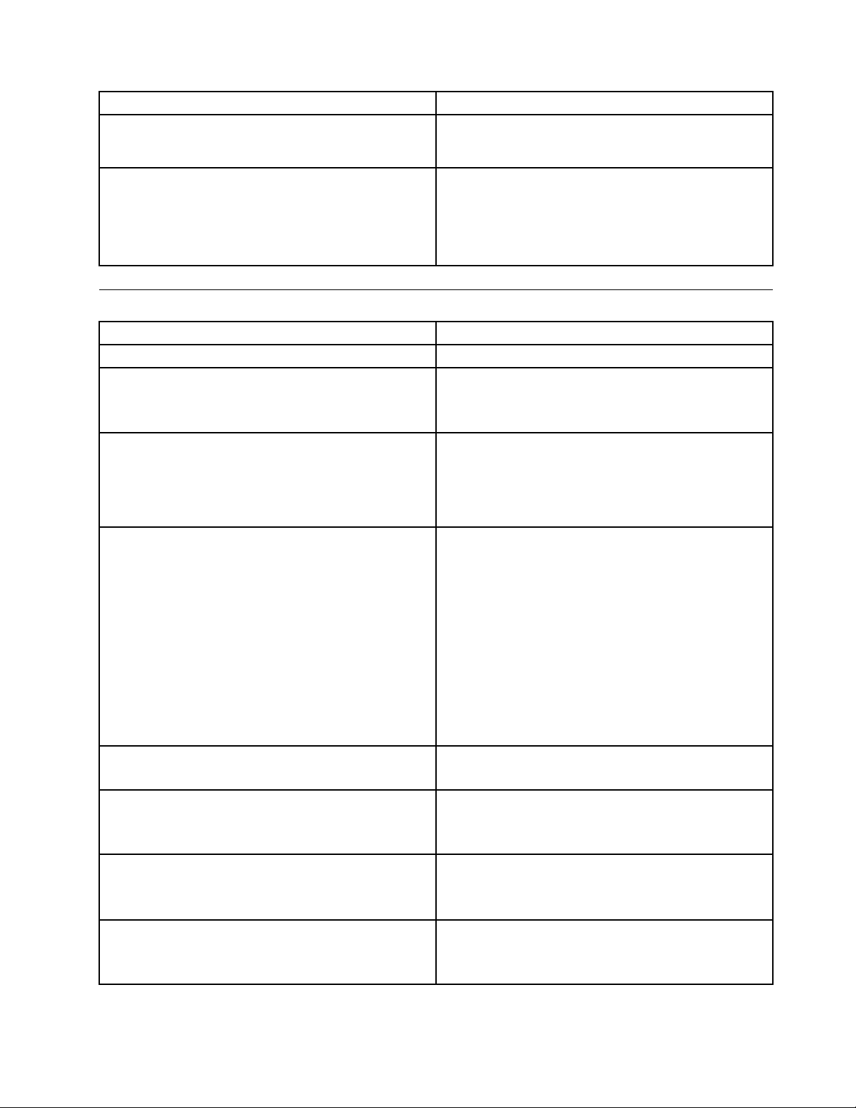
POSTErrorMessageDescription/Action
PressTABtoshowPOSTscreen
Error:Non-SystemdiskordiskerrorReplaceandpress
anykeywhenready
PressingtheTABkeypermitstheusertotogglebetween
thedefaultPOSTdisplayscreenandacustomPOST
displayscreen.
TheBIOSwasunabletondasuitablebootdevice.
Makesurethebootdriveisproperlyconnectedtothe
computer.
Makesureyouhavebootablemedia.
Miscellaneouserrormessages
Message/SymptomFRU/Action
ChangingdisplaycolorsDisplay/Monitor
Computerwillnotpower-off.See"Harddiskdriveboot
error"onpage43
ComputerwillnotRPLfromserver
ComputerwillnotperformaWakeOnLAN®(ifapplicable)1.Checkpowersupplyandsignalcableconnections
Deadcomputer.See"Harddiskdrivebooterror"on
page43.
Diskettedrivein-uselightremainsonordoesnotlight
whendriveisactive.
Flashingcursorwithanotherwiseblankdisplay.
IncorrectmemorysizeduringPOST
.
1.PowerSwitch
2.SystemBoard
3.Risercard,ifinstalled
1.Ensurethatnetworkisinstartupsequenceasrst
deviceorrstdeviceafterdiskette
2.EnsurethatnetworkadapterisenabledforRPL
3.Networkadapter(Advisenetworkadministratorofnew
MACaddress)
tonetworkadapter
2.Ensurethattheoperatingsystemsettingsaresetto
enableWakeonLAN®
3.EnsureWakeOnLANfeatureisenabledin
Setup/Conguration(see"StartingtheSetupUtility
program"onpage39
4.EnsurenetworkadministratorisusingcorrectMAC
address
5.EnsurenointerruptorI/Oaddressconicts
6.Networkadapter(advisenetworkadministratorofnew
MACaddress)
1.PowerSupply
2.SystemBoard
1.DisketteDrive
2.SystemBoard
3.DisketteDriveCable
1.SystemBoard
2.PrimaryHardDiskDrive
3.HardDiskDriveCable
1.RuntheMemorytests
2.MemoryModule
3.SystemBoard
)
Chapter7Symptom-to-FRUIndex63
Page 70
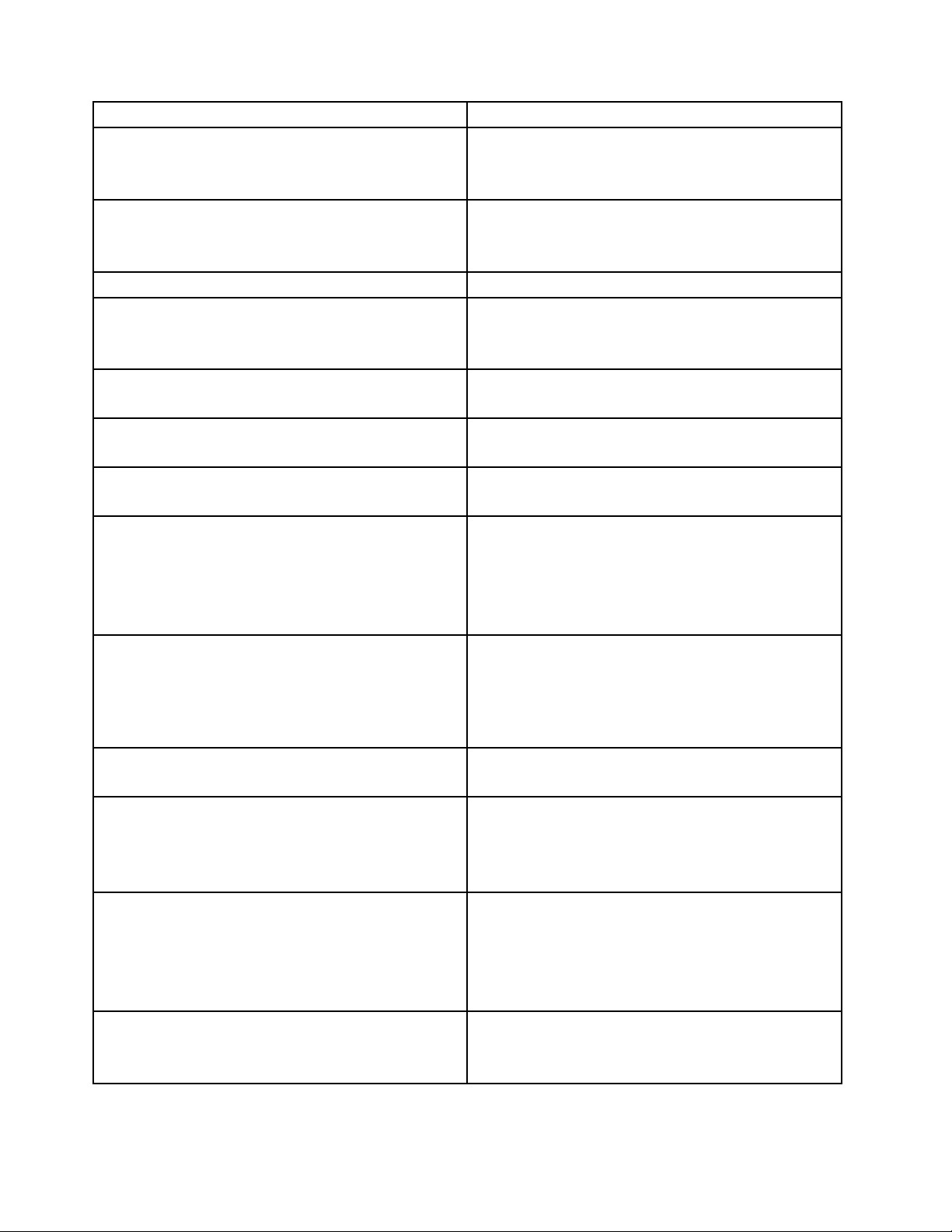
Message/SymptomFRU/Action
"InsertaDiskette"iconappearswithaknown-good
diagnosticsdisketteintherst3.5-inchdiskettedrive.
Intensityorcolorvariesfromlefttorightofcharacters
andcolorbars
Nopowerorfannotrunning
Non-systemdiskordiskerror-typemessagewitha
known-gooddiagnosticdiskette.
Otherdisplaysymptomsnotlistedabove(includingblank
orillegibledisplay)
Power-onindicatororharddiskdrivein-uselightnoton,
butcomputerworkscorrectly
Printerproblems1.Printer
Programloadsfromtheharddiskwithaknown-good
diagnosticsdisketteintherst3.5-inchdiskettedrive
RPLcomputercannotaccessprogramsfromitsownhard
disk.
RPLcomputerdoesnotRPLfromserver
Serialorparallelportdevicefailure(systemboardport)1.ExternalDeviceSelf- T estOK?
Serialorparallelportdevicefailure(adapterport)1.ExternalDeviceSelf- T estOK?
Someorallkeysonthekeyboarddonotwork
1.SystemBoard
2.DisketteDriveCable
3.NetworkAdapter
1.Display
2.Videoadapter(ifpresent)
3.SystemBoard
1.See"Harddiskdrivebooterror"onpage43.
1.DisketteDrive
2.SystemBoard
3.DisketteDriveCable
1.Display
2.SystemBoard
1.Powerswitch/LEDassembly
2.SystemBoard
2.SystemBoard
1.RunSetupandcheckStartupsequence.
2.DisketteDrive
3.DisketteDriveCable
4.SystemBoard
5.PowerSupply
1.IfnetworkadministratorisusingLCCMHybrid
RPL,checkstartupsequence:
a.Firstdevice-network
b.Seconddevice-harddisk
2.Harddiskdrive
1.Checkstartupsequence
2.CheckthenetworkadapterLEDstatus
2.ExternalDevice
3.Cable
4.SystemBoard
2.ExternalDevice
3.Cable
4.AlternateAdapter
5.SystemBoard
1.Keyboard
2.KeyboardCable
3.SystemBoard
64ThinkCentreHardwareMaintenanceManual
Page 71

Undeterminedproblems
IfthiscomputerhasaparallelATAharddiskdrive,makesurethattheharddiskdriveisjumperedasa
masterandtheopticaldriveisjumperedasaslave.
1.Power-offthecomputer.
2.Removeordisconnectthefollowingcomponents(ifinstalled)oneatatime.
a.Externaldevices(modem,printer,ormouse)
b.Anyadapters
c.Memorymodules
d.Extendedvideomemory
e.ExternalCache
f.ExternalCacheRAM
g.Harddiskdrive
h.Diskettedrive
3.Power-onthecomputertore-testthesystem.
4.Repeatsteps1through3untilyoundthefailingdeviceoradapter.
Ifalldevicesandadaptershavebeenremoved,andtheproblemcontinues,replacethesystemboard.
Chapter7Symptom-to-FRUIndex65
Page 72

66ThinkCentreHardwareMaintenanceManual
Page 73
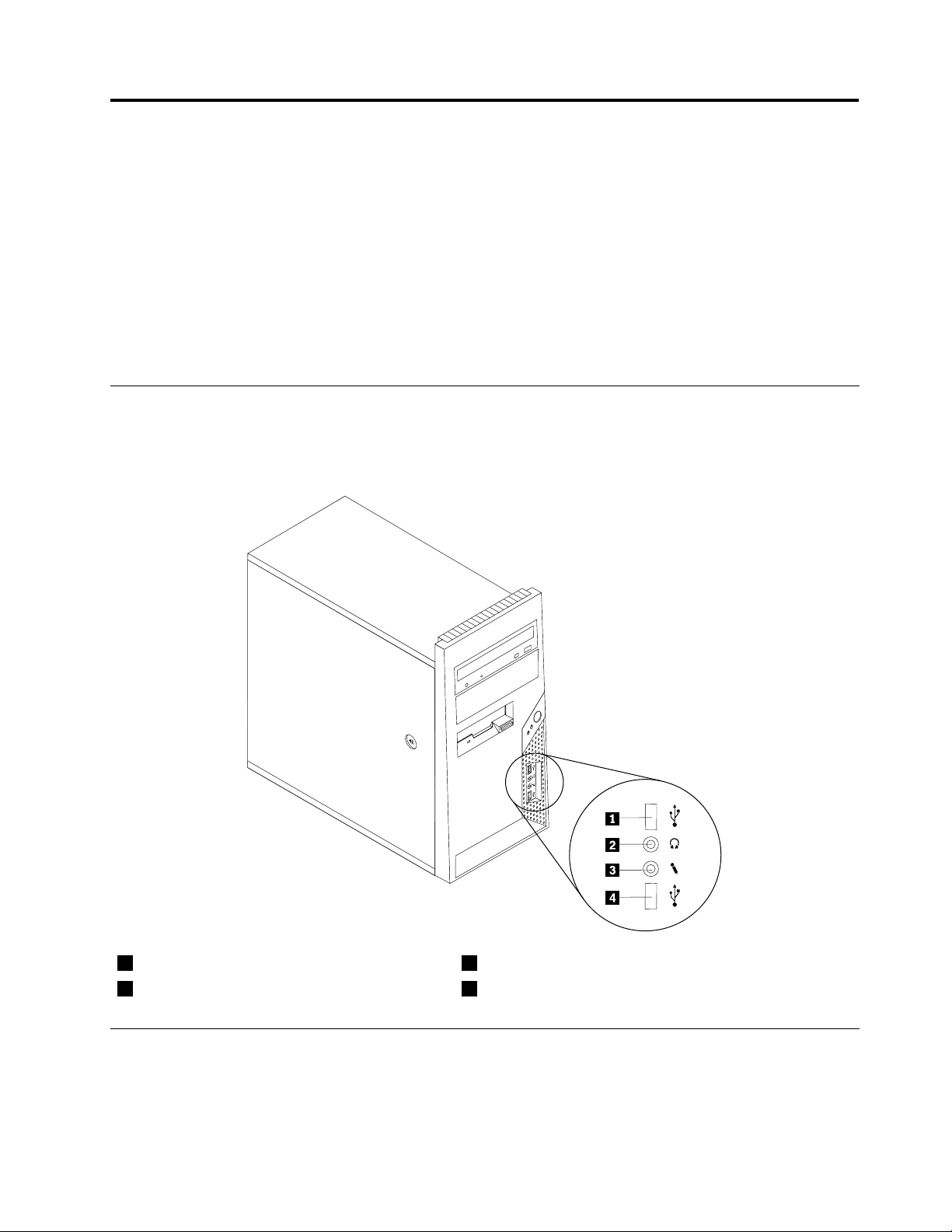
Chapter8.ReplacingFRUs(Types7061,7090,9353,9421,
9485,9623,9625,9705,9786,9795,9935,9946,9953)
Important
BeforeyoureplaceanyFRU,readChapter2"Safetyinformation"onpage3.Theseprecautionsand
guidelineswillhelpyouworksafely.
FRUreplacementsaretobedonebytrainedservicetechniciansonly.
ThischapterdoesnotcontainaremoveandreplaceprocedureforallFRUs.OnlythemajorFRUsare
documented.
Locatingcontrolsandconnectorsonthefrontofyourcomputer
Thefollowingillustrationshowsthelocationofthecontrolsandconnectorsonthefrontofyourcomputer.
Note:Notallcomputermodelswillhavethefollowingcontrolsandconnections.
1
2
USBconnector
Headphoneconnector
3
4
Microphoneconnector
USBconnector
Rearconnectors
Thefollowingillustrationshowsthelocationsoftheconnectorsontherearofthecomputer.
©CopyrightLenovo2008,2010
67
Page 74
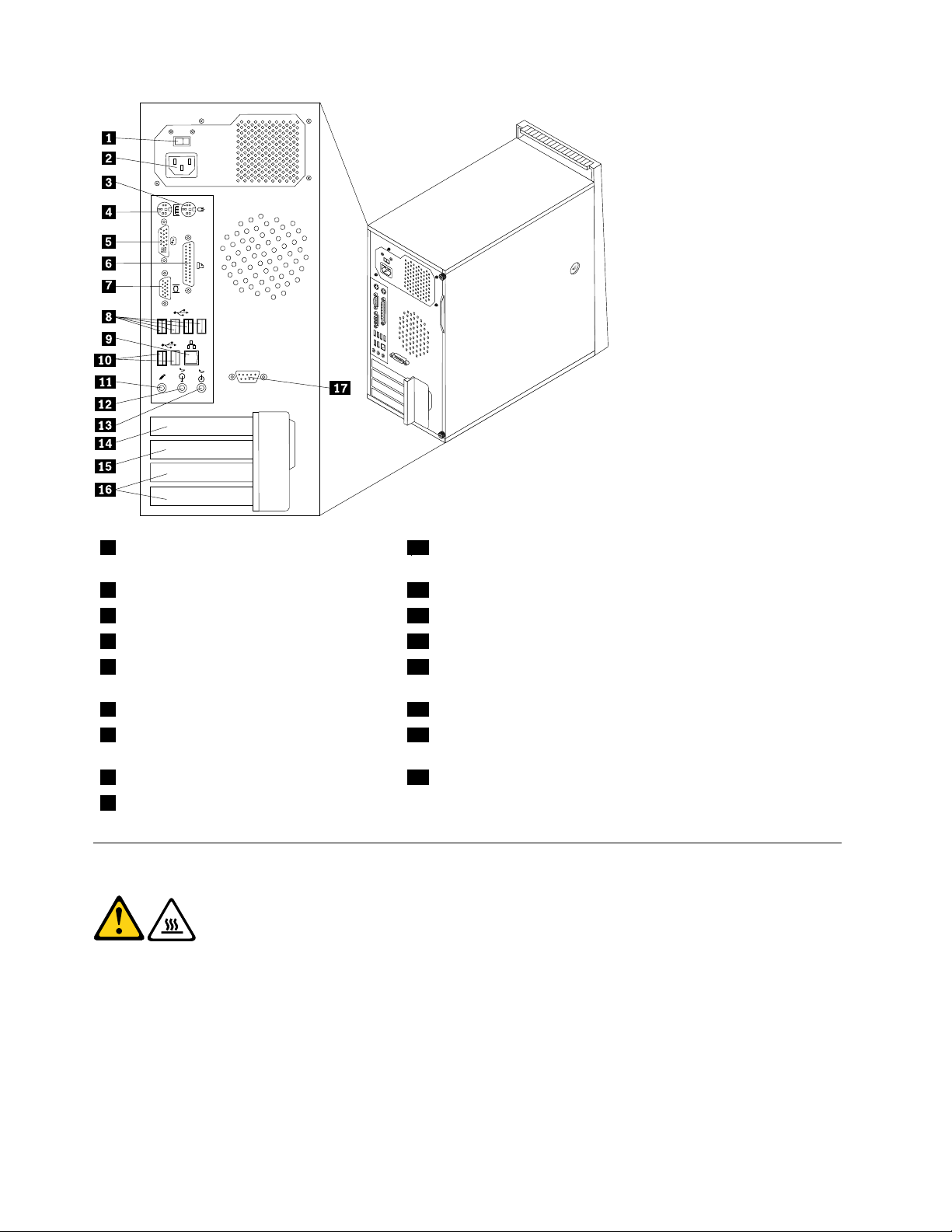
1
Voltageselectionswitch(some
10
USBconnectors(2)
models)
2
3
4
5
Powercordconnector
Standardmouseconnector
Standardkeyboardconnector
Digitalvideointerface(DVI)monitor
11
12
13
14
Microphoneconnector
Audioline-outconnector
Audioline-inconnector
PCIExpressx1adapterconnector
connector
6
7
Parallelconnector
Videographicsarray(VGA)monitor
15
16
PCIExpressx16graphicsadapterconnector
PCIadapterconnectors(2)
connector
8
9
USBconnectors(4)
Ethernetconnector
17
Serialconnector(somemodels)
Removingthecover
CAUTION:
Theheatsinkandmicroprocessormightbeveryhot.Turnoffthecomputerandwait
threetoveminutestoletthecomputercoolbeforeopeningthecomputercover.
Thissectionprovidesinstructionsonhowtoremovethecover.
Toremovethecover,dothefollowing:
1.Shutdowntheoperatingsystem,removeanymedia(DVDs,CDs,ortapes)fromthedrives,andturnoff
allattacheddevices.
2.Unplugallpowercordsfromelectricaloutlets.
68ThinkCentreHardwareMaintenanceManual
Page 75
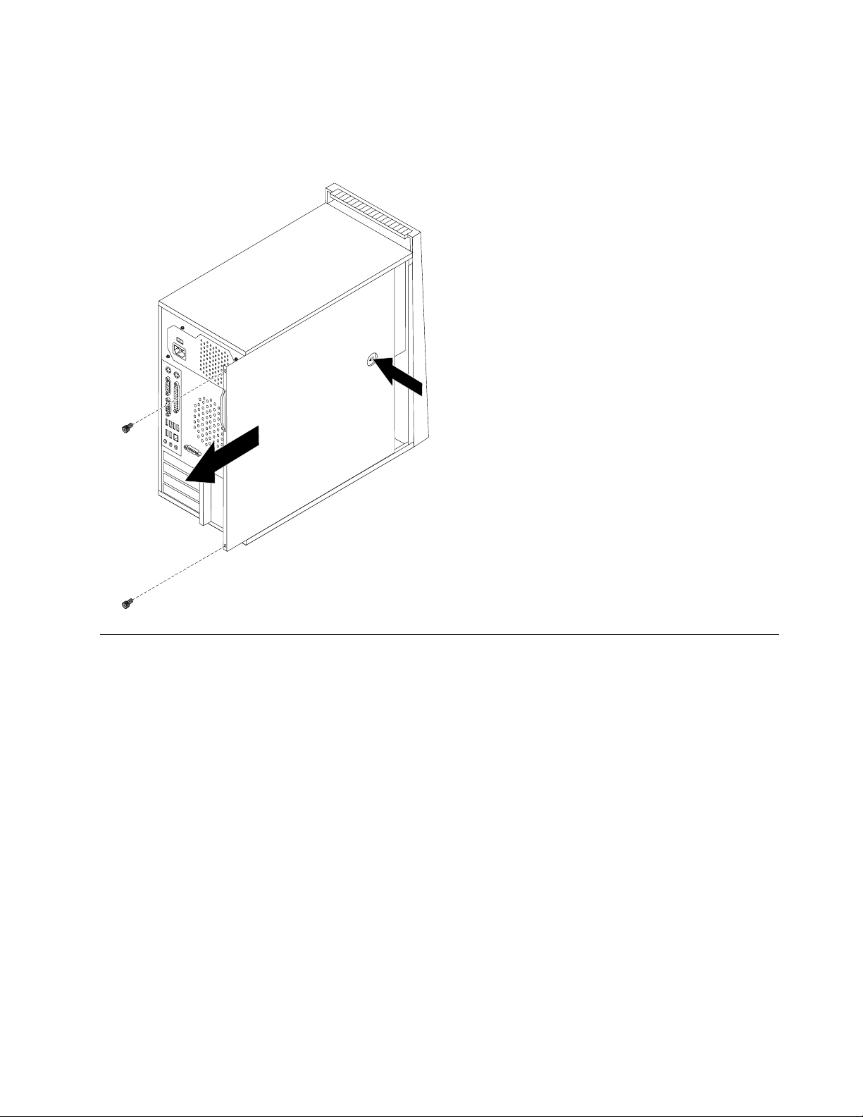
3.Disconnectallcablesattachedtothecomputer.Thisincludespowercords,input/output(I/O)cables,
andanyothercablesthatareconnectedtothecomputer.
4.Iftherearethumbscrewssecuringthecover,removethem.
5.Pressthebuttonontheleft-sidecoverandslidethecovertothereartoremove.
Locations
Toremovethecomputercover,see"Removingthecover"onpage68.
ThefollowingillustrationwillhelpyoulocatethemajorFRUsinthecomputer.
Chapter8ReplacingFRUs(T ypes7061,7090,9353,9421,9485,9623,9625,9705,9786,9795,9935,9946,9953)69
Page 76
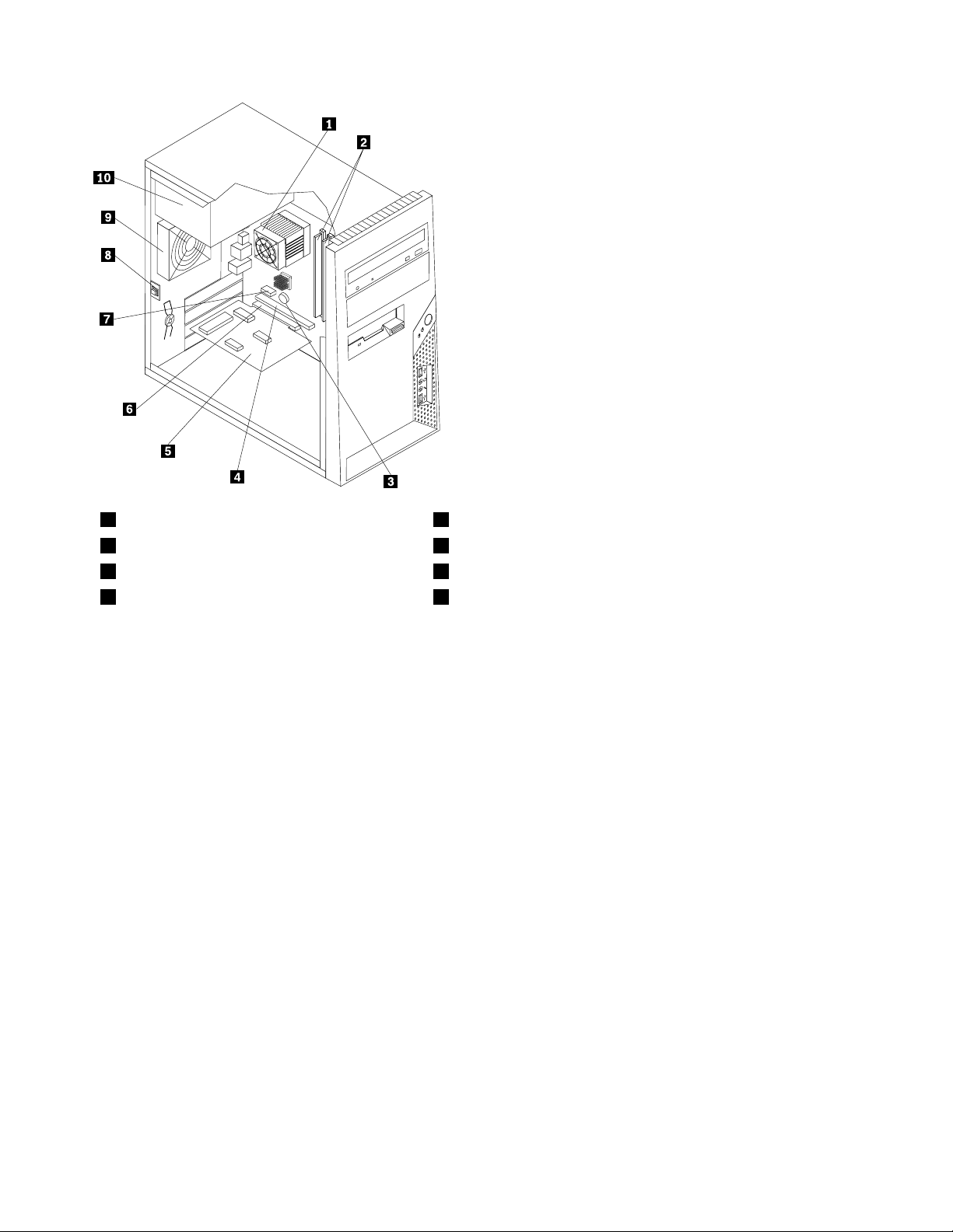
1
2
3
4
Microprocessorfanandheatsink
Memorymodules
Battery
PCIExpressx16graphicsadapter
6
7
8
9
PCIadapterconnector
PCIExpressx1adapterconnector
Coverpresence(Intrusion)switch
Rearfanassembly
connector
70ThinkCentreHardwareMaintenanceManual
Page 77
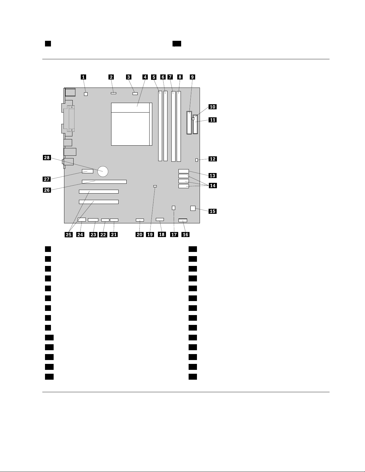
5
PCIadaptercard
Locatingpartsonthesystemboard
10
Powersupply
1
2
3
4
5
6
7
8
9
10
11
12
13
14
4-pinpowerconnector
Systemfanconnector
Microprocessorfanconnector
Microprocessorandheatsink
Memoryconnector1
Memoryconnector2
Memoryconnector3
Memoryconnector4
24-pinpowerconnector
Thermalsensorconnector
Diskettedriveconnector
Coverpresence(Intrusion)switchconnector
SATAconnector
SATAconnectors(3)
15
16
17
18
19
20
21
22
23
24
25
26
27
28
Powerfanconnector
Frontpanelconnector
Internalspeakerconnector
FrontUSBconnector2
ClearCMOS/Recoveryjumper
FrontUSBconnector1
Serial(COM2)connector
Serial(COMl)connector
CD-INconnector
Frontaudioconnector
PCIadapterconnectors(2)
PCIExpressx16graphicsadapterconnector
PCIExpressx1adapterconnector
Battery
Removingandreplacingthefrontbezel
Thissectionprovidesinformationonhowtoremoveandreplacethefrontbezel.
Toinstallorreplacethefrontbezel:
Chapter8ReplacingFRUs(T ypes7061,7090,9353,9421,9485,9623,9625,9705,9786,9795,9935,9946,9953)71
Page 78
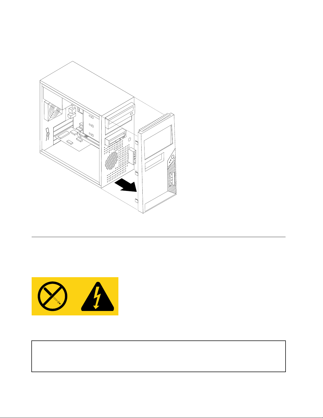
1.Removethecomputercover.See"Removingthecover"onpage68.
2.Removethefrontbezelbyreleasingthethreeplastictabsinsidethechassisandpivotingthebezel
outward.Carefullysetthebezeltothesidewithoutdisconnectingthepowerswitch/LEDassemblycable.
3.T oreinstallthebezel,aligntheplastictabsontherightsideofthebezelwiththecorrespondingholesin
thechassis,thenpivotitinwarduntilitsnapsintopositionontheleftside.
Replacingthepowersupply
Attention
Neverremovethecoveronapowersupplyoranypartthathasthefollowinglabelattached.
Hazardousvoltage,current,andenergylevelsarepresentinsideanycomponentthathasthislabelattached.
Therearenoservicablepartsinsidethesecomponents.
Attention
Donotopenyourcomputerorattemptanyrepairbeforereadingandunderstandingthe"Importantsafetyinformation"
intheThinkCentreSafetyandWarrantyGuidethatcamewithyourcomputer.T oobtainacopyoftheThinkCentre
SafetyandWarrantyGuide,goto:http://www.lenovo.com/support
72ThinkCentreHardwareMaintenanceManual
Page 79
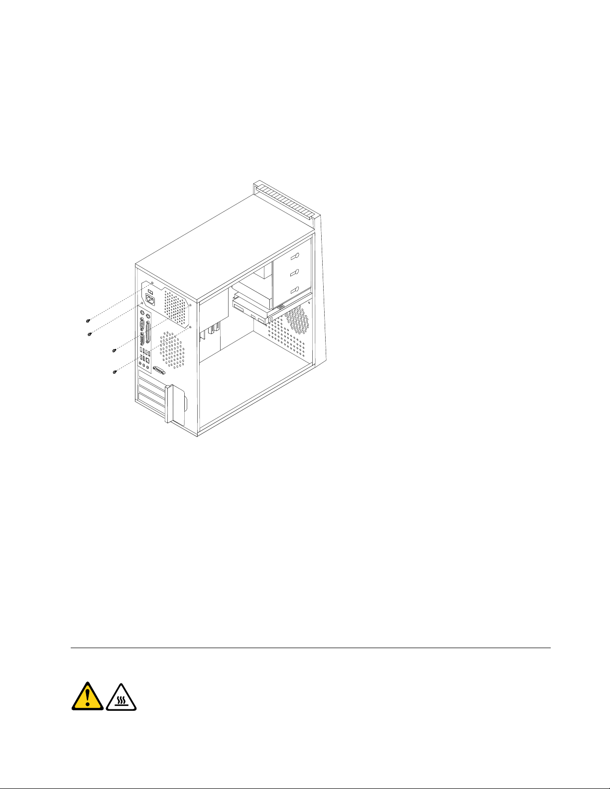
Thissectionprovidesinformationonhowtoremoveandreplacethepowersupply.
Toremoveorreplacethepowersupply,dothefollowing:
1.Removethecomputercover.See"Removingthecover"onpage68.
Note:Forthisprocedure,ithelpstolaythecomputeronitsside.
2.Disconnectthepowersupplycablesfromthesystemboardandfromalldrives.
3.Removethefourscrewsthatsecurethepowersupplyattherearofthechassis.
4.Liftthepowersupplyoutofthechassis.
5.Ifthepowersupplyhasavoltage-selectionswitch,ensurethatitissettomatchthevoltageavailable
attheelectricaloutlet.
•Ifthevoltagesupplyrangeinyourlocalcountryorregionis100-127Vac,settheswitchto115V.
•Ifthevoltagesupplyrangeinyourlocalcountryorregionis200-240Vac,settheswitchto230V.
6.Installthenewpowersupplyintothechassissothatthescrewholesinthepowersupplyalignwith
thoseinthechassis.
7.Installthefourscrewstosecurethepowersupply.
Note:UseonlythescrewsprovidedbyLenovo.
8.Reconnectthepowersupplyconnectorstothesystemboard.See"Locatingpartsonthesystem
board"onpage71.
9.Reconnectapowersupplyconnectortoeachofthedrives.
10.Goto"CompletingtheFRUreplacement"onpage91.
Replacingthesystemboard
CAUTION:
Theheatsinkandmicroprocessormightbeveryhot.Turnoffthecomputerandwait
threetoveminutestoletthecomputercoolbeforeopeningthecomputercover.
Chapter8ReplacingFRUs(T ypes7061,7090,9353,9421,9485,9623,9625,9705,9786,9795,9935,9946,9953)73
Page 80
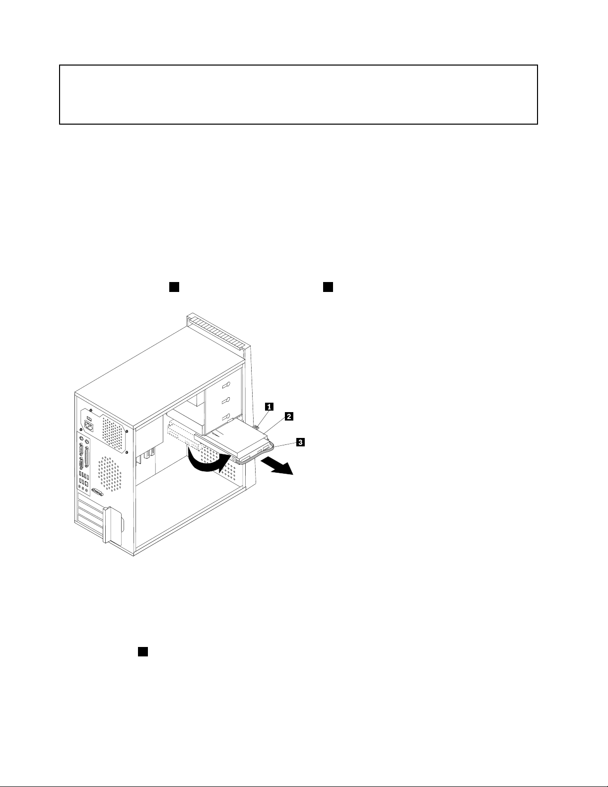
Attention
Donotopenyourcomputerorattemptanyrepairbeforereadingandunderstandingthe"Importantsafetyinformation"
intheThinkCentreSafetyandWarrantyGuidethatcamewithyourcomputer.T oobtainacopyoftheThinkCentre
SafetyandWarrantyGuide,goto:http://www.lenovo.com/support
Note:Whenreplacingthesystemboardyoumustalsoorderanewretentionmoduleforthenewsystem
board.Makesureyouhavearetentionmoduleforthenewsystemboardbeforecontinuingwiththis
procedure.
Thissectionprovidesinstructionsonhowtoremoveandinstallthesystemboard.
Toreplacethesystemboard,dothefollowing:
1.Removethesidecover.See"Removingthecover"onpage68.
2.Placethecomputeronitsrightsidetohelpmakethesystemboardmoreaccessible.
3.RemoveanyPCIadaptercardsinstalled."ReplacingaPCIadaptercard"onpage80
4.Disconnectthesignalandpowercablesfromtheharddiskdrive.
5.Pressthereleasetab1down,slidetheharddrivecage2back,andpivottheharddiskdriveoutward
asshown.
6.Carefullytakenoteofthelocationofallcableconnectionsonthesystemboardanddisconnectallcables.
See"Locatingpartsonthesystemboard"onpage71
.
7.Removethescrewsthatsecurethesystemboardtothechassis.
8.Liftthesystemboardoutofthechassis.
9.Removethememorymodulesfromthefailingsystemboardandinstalltheminthesamelocationon
thenewsystemboard.
10.Rotatehandle1toreleasetheheatsinkclampandthendisengagetheclampfromtheplasticretention
bracket.
74ThinkCentreHardwareMaintenanceManual
Page 81
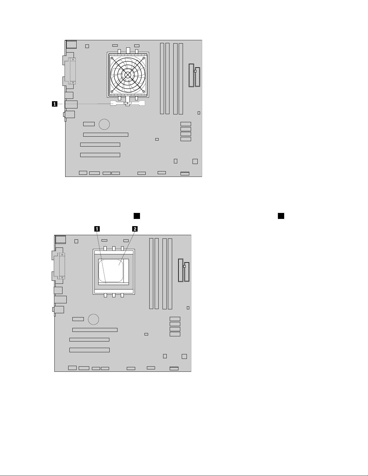
11.Lifttheheatsinkandfanassemblyoffthefailingsystemboard.Placetheheatsinkonitssidesothatthe
thermalgreasedoesnotcomeincontactwithanything.
12.Removetheretentionmodulefromtherearofthefailingsystemboardandinstallitinthesameposition
onthenewsystemboard.
13.Toreleasethemicroprocessor2fromthesystemboardsocket,liftthesmallhandle1.
Important:Touchonlythesidesofthemicroprocessor.Donottouchthegoldcontactsonthebottom.
14.Liftthemicroprocessorstraightupandoutofthesocket.
Chapter8ReplacingFRUs(T ypes7061,7090,9353,9421,9485,9623,9625,9705,9786,9795,9935,9946,9953)75
Page 82
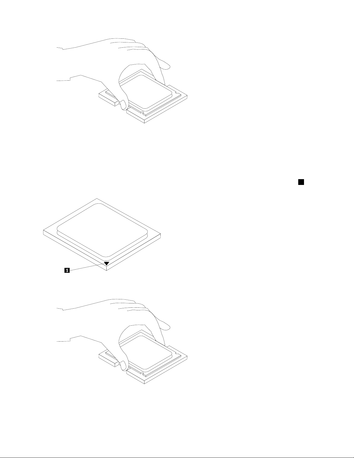
Notes:
a.Yourmicroprocessorandsocketmightlookdifferentthantheoneillustrated.
b.Notetheorientationofthemicroprocessorinthesocket.Lookforthesmalltriangleononecornerof
themicroprocessor.Thisisimportantwhenreinstallingthemicroprocessoronthenewsystemboard.
c.Donotdropanythingontothemicroprocessorsocketwhileitisexposed.Thesocketpinsmustbe
keptascleanaspossible.
15.Holdingthemicroprocessorwithyourngers,positionthemicroprocessorsothatthesmalltriangle1on
onecornerisalignedwiththecorrespondingtriangleonthesocketonthenewsystemboard.
16.Makesurethatthesmallhandleisintheraisedposition.
17.Lowerthemicroprocessorstraightdownintothesystemboardsocketofthenewsystemboard.
18.Lowerthesmallhandletosecurethemicroprocessorinthesocket.
19.Positiontheheatsinkonthemicroprocessorsocketandthenpositiontheclampontheplasticretention
bracket.Pivotthehandletoclamptheheatsinktotheplasticretentionbracket.
76ThinkCentreHardwareMaintenanceManual
Page 83
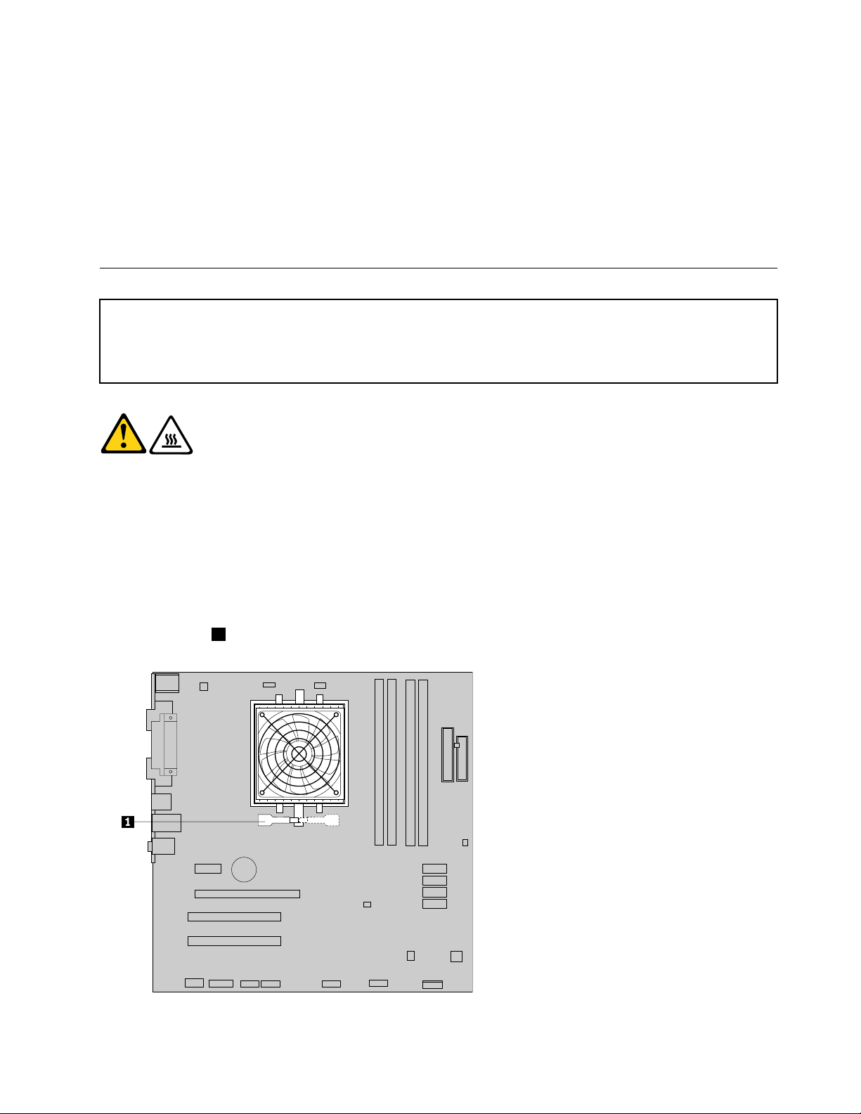
20.Connecttheheatsinkandfanassemblycabletothesystemboard.See"Locatingpartsonthesystem
board"onpage71.
21.Installthenewsystemboardintothechassisandalignthescrewholeswiththoseinthechassis.Insert
andtightenthescrewsthatsecurethesystemboard.
22.Pivottheharddiskdrivebackintoposition.
23.Connectthepowerandsignalcablestotheharddiskdrive.
24.Connectallremainingcablestothesystemboard.See"Locatingpartsonthesystemboard"onpage71.
25.Goto"CompletingtheFRUreplacement"onpage91.
Replacingthemicroprocessor
Attention
Donotopenyourcomputerorattemptanyrepairbeforereadingandunderstandingthe"Importantsafetyinformation"
intheThinkCentreSafetyandWarrantyGuidethatcamewithyourcomputer.T oobtainacopyoftheThinkCentre
SafetyandWarrantyGuide,goto:http://www.lenovo.com/support
CAUTION:
Theheatsinkandmicroprocessormightbeveryhot.Turnoffthecomputerandwait
threetoveminutestoletthecomputercoolbeforeopeningthecomputercover.
Thissectionprovidesinformationonhowtoremoveandreplacethemicroprocessor.
Toremoveorreplacethemicroprocessor,dothefollowing:
1.Removethecover.See"Removingthecover"onpage68.
2.Placethecomputeronitsrightsidetohelpmakethemicroprocessormoreaccessible.
3.Disconnecttheheatsinkandfanassemblycablefromthesystemboard.See"Locatingpartsonthe
systemboard"onpage71.
4.Rotatehandle1toreleasetheheatsinkclampandthendisengagetheclampfromtheplasticretention
bracket.
Chapter8ReplacingFRUs(T ypes7061,7090,9353,9421,9485,9623,9625,9705,9786,9795,9935,9946,9953)77
Page 84
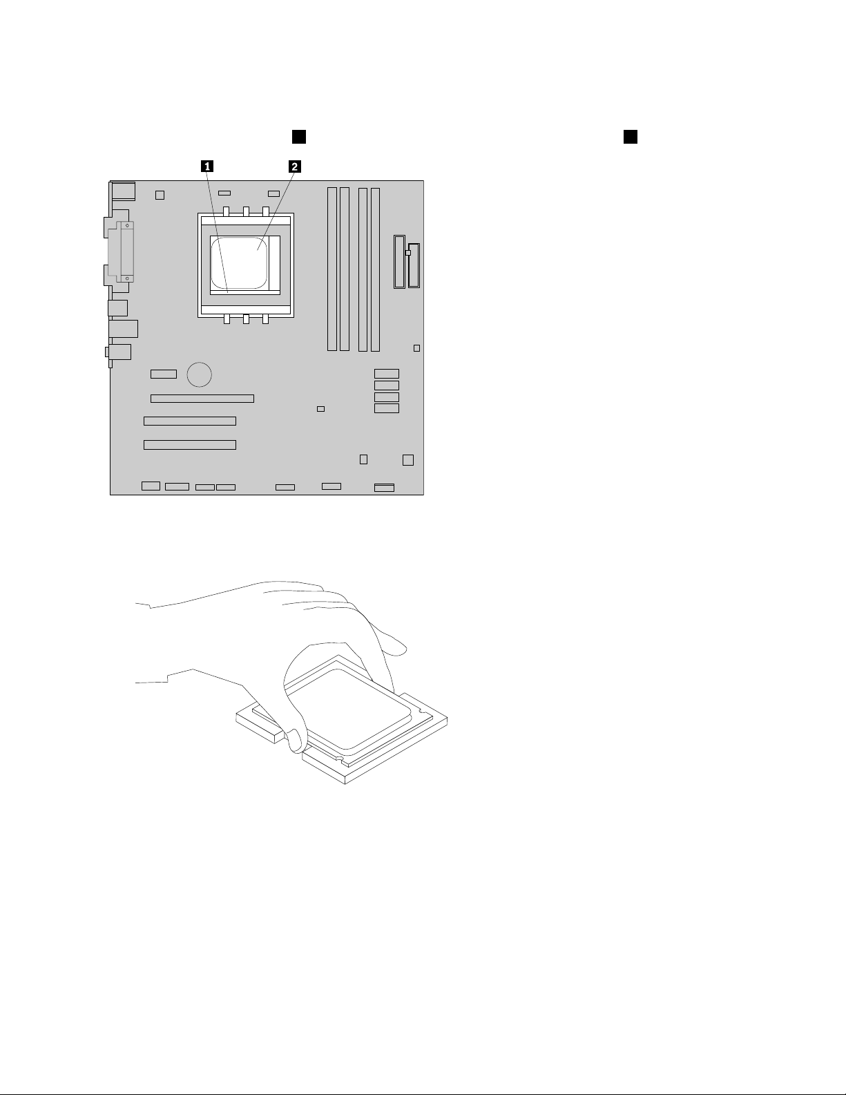
5.Lifttheheatsinkandfanassemblyoffthesystemboard.Placetheheatsinkonitssidesothatthe
thermalgreasedoesnotcomeincontactwithanything.
6.T oreleasethemicroprocessor2fromthesystemboardsocket,liftthesmallhandle1.
Important:Donottouchthegoldcontactsonthebottomofthemicroprocessor.Ifyoumusttouchthe
microprocessor,touchonlythesides.
7.Liftthemicroprocessorstraightupandoutofthesocket.
a.Yourmicroprocessorandsocketmightlookdifferentthantheoneillustrated.
b.Notetheorientationofthemicroprocessorinthesocket.Lookforthesmalltriangleononecornerof
themicroprocessor.Thisisimportantwhenreinstallingthemicroprocessoronthenewsystemboard.
c.Donotdropanythingontothemicroprocessorsocketwhileitisexposed.Thesocketpinsmustbe
keptascleanaspossible.
8.Makesurethatthesmallhandleisintheraisedposition.
9.Holdingthemicroprocessorwithyourngers,positionthemicroprocessorsothatthesmalltriangleon
onecornerisalignedwiththecorrespondingtriangleonthemicroprocessorsocket.
78ThinkCentreHardwareMaintenanceManual
Page 85
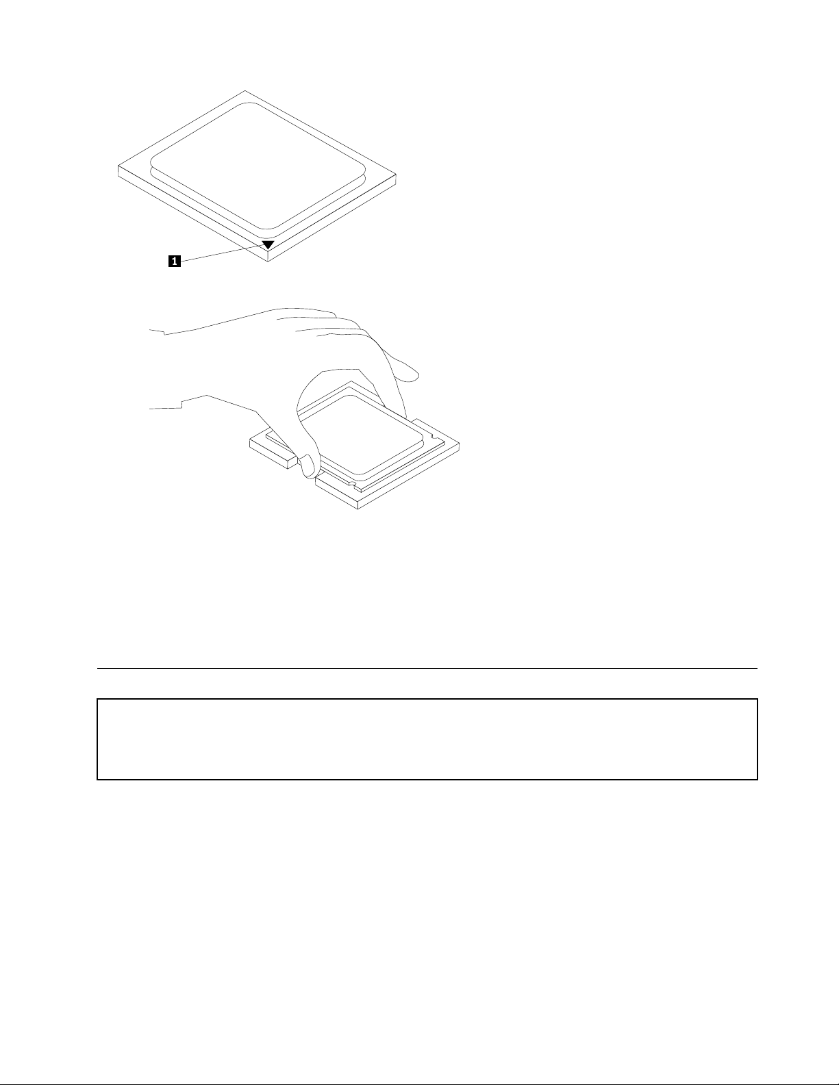
10.Lowerthemicroprocessorstraightdownintothesystemboardsocketofthenewsystemboard.
11.Lowerthesmallhandletosecurethemicroprocessorinthesocket.
12.Positiontheheatsinkonthemicroprocessorsocketandthenpositiontheclampontheplasticretention
bracket.Pivotthehandletoclamptheheatsinktotheplasticretentionbracket.
13.Installtheheatsinkandfanassemblyonthesystemboard.
14.Connecttheheatsinkandfanassemblycabletothesystemboard.See"Locatingpartsonthesystem
board"onpage71
.
15.Goto"CompletingtheFRUreplacement"onpage91.
Replacingamemorymodule
Attention
Donotopenyourcomputerorattemptanyrepairbeforereadingandunderstandingthe"Importantsafetyinformation"
intheThinkCentreSafetyandWarrantyGuidethatcamewithyourcomputer.T oobtainacopyoftheThinkCentre
SafetyandWarrantyGuide,goto:http://www.lenovo.com/support
Thissectionprovidesinformationonhowtoremoveandreplaceamemorymodule.
Toremoveorreplacethememorymodule,dothefollowing:
1.Removethecomputercover.See"Removingthecover"onpage68.
Note:Forthisprocedure,ithelpstolaythecomputeronitsside.
2.Locatethememorymoduleconnectors.See"Locatingpartsonthesystemboard"onpage71.
Chapter8ReplacingFRUs(T ypes7061,7090,9353,9421,9485,9623,9625,9705,9786,9795,9935,9946,9953)79
Page 86
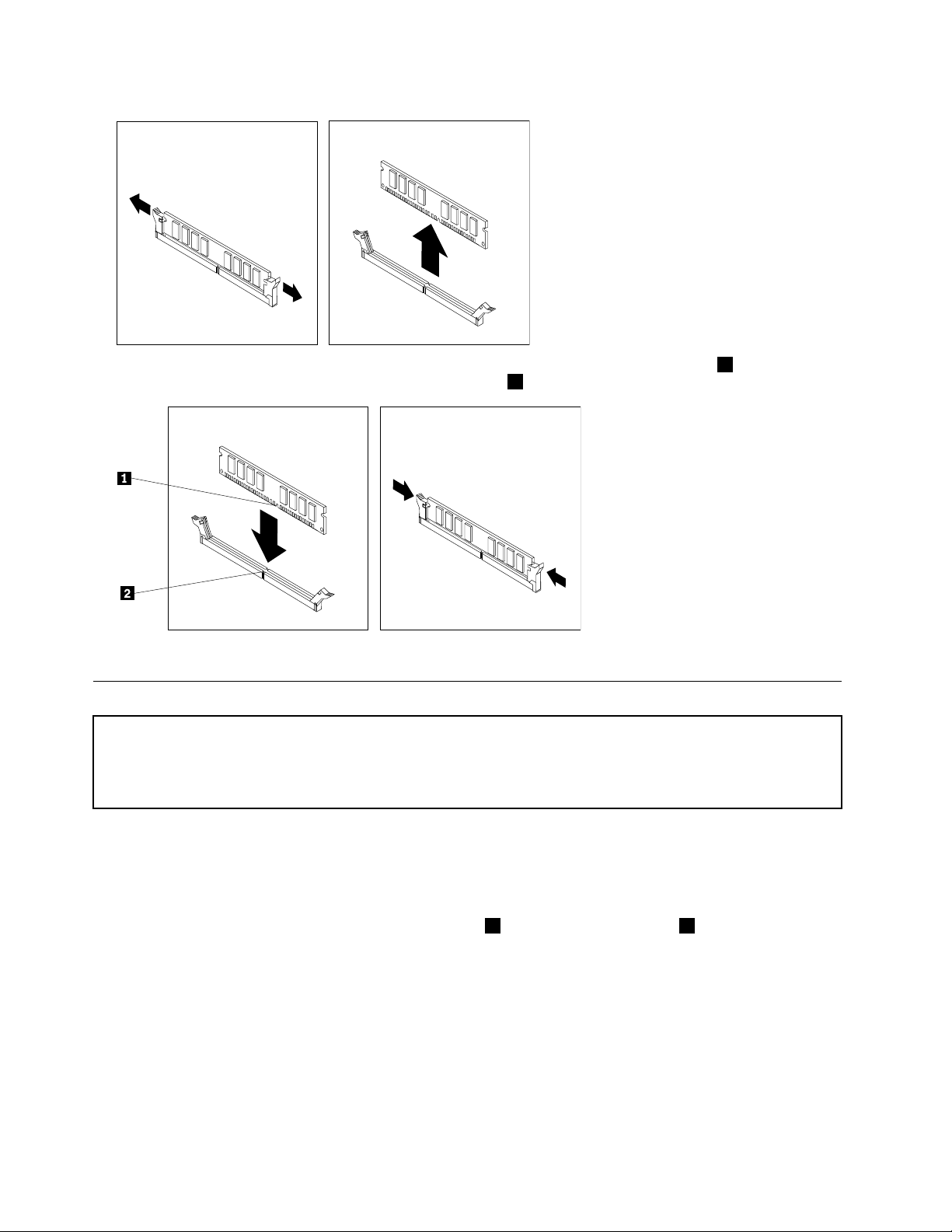
3.Removethememorymodulebeingreplacedbyopeningtheretainingclipsasshown.
4.Positionthenewmemorymoduleoverthememoryconnector.Makesurethenotch1
onthememoryalignscorrectlywiththeconnectorkey2onthesystemboard.Push
thememorymodulestraightdownintotheconnectoruntiltheretainingclipsclose.
5.Goto"CompletingtheFRUreplacement"onpage91.
ReplacingaPCIadaptercard
Attention
Donotopenyourcomputerorattemptanyrepairbeforereadingandunderstandingthe"Importantsafetyinformation"
intheThinkCentreSafetyandWarrantyGuidethatcamewithyourcomputer.T oobtainacopyoftheThinkCentre
SafetyandWarrantyGuide,goto:http://www.lenovo.com/support
ThissectionprovidesinformationonhowtoremoveandreplaceaPCIadaptercard.
ToremoveorreplaceaPCIadaptercard,dothefollowing:
1.Removethecomputercover.See"Removingthecover"onpage68.
2.Attherearofthecomputer,pressthereleasebutton1toopentheadapterlatch2andremovethe
slotcover.
80ThinkCentreHardwareMaintenanceManual
Page 87
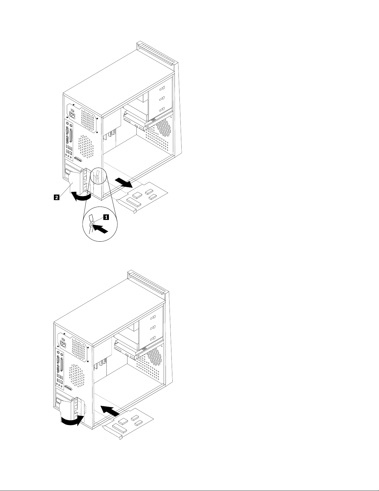
3.Removetheadapterfromitsstatic-protectivepackage.
4.Installthenewadapterintothesameadapterconnector.
5.Ensuretheadapterisfullyseatedintotheadapterconnector.
Chapter8ReplacingFRUs(T ypes7061,7090,9353,9421,9485,9623,9625,9705,9786,9795,9935,9946,9953)81
Page 88
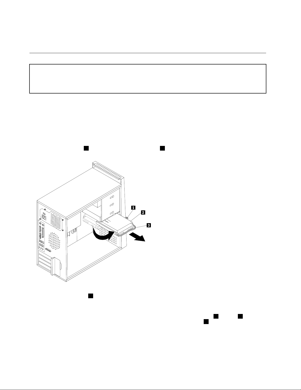
6.Attherearofthecomputer,pivottheadapterlatchtotheclosedpositiontosecuretheadapter.
7.Goto"CompletingtheFRUreplacement"onpage91.
Replacingtheharddiskdrive
Attention
Donotopenyourcomputerorattemptanyrepairbeforereadingandunderstandingthe"Importantsafetyinformation"
intheThinkCentreSafetyandWarrantyGuidethatcamewithyourcomputer.T oobtainacopyoftheThinkCentre
SafetyandWarrantyGuide,goto:http://www.lenovo.com/support
Thissectionprovidesinformationonhowtoremoveandreplacetheharddiskdrive.
Toremoveorreplacetheharddiskdrive,dothefollowing:
1.Removethecomputercover.See"Removingthecover"onpage68.
Note:Forthisprocedure,ithelpstolaythecomputeronitsside.
2.Disconnectthesignalandpowercablesfromtheharddiskdrive.
3.Pressthereleasetab1down,slidetheharddrivecage2back,andpivottheharddiskdriveoutward
asshown.
4.Removetheharddiskdrivecagefromthechassisbysimplyslidingitoutward.
5.Pullonthebluehandle3toremoveharddiskdrivefromthedrivecage.
6.Removethefailingharddiskdrivefromtheblueplasticbracketfrombyexingthesidesofthebracket
enoughtofreeitfromtheharddiskdrive.
7.T oinstallthenewdriveintothebluebracket,exthebracket,andalignthepins1through4onthe
bracketwiththeholesintheharddiskdrive.Donottouchthecircuitboard5onthebottomofthe
harddiskdrive.
82ThinkCentreHardwareMaintenanceManual
Page 89
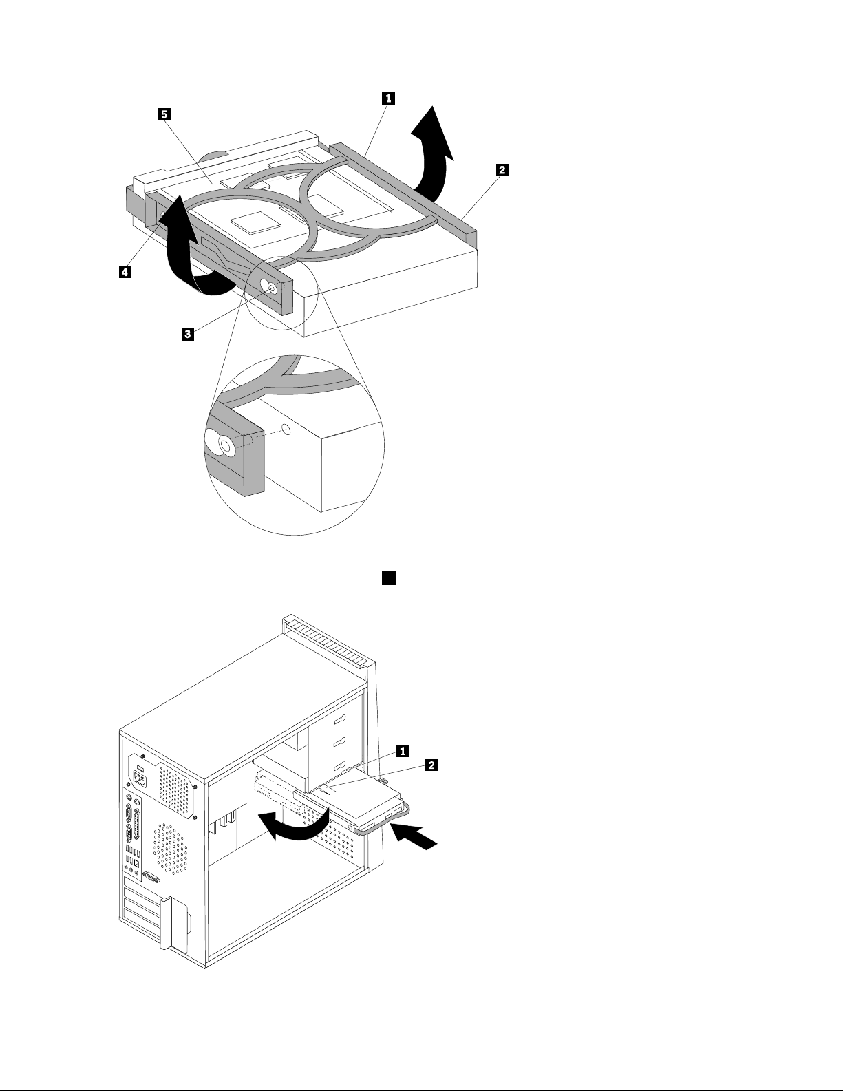
8.Slidethenewharddiskdriveintothedrivecageuntilitsnapsintoposition.
9.Alignthedrivecagepivotpinwiththeslot1intheupperdrivecageandslidetheharddiskdrive
intothechassis.
Chapter8ReplacingFRUs(T ypes7061,7090,9353,9421,9485,9623,9625,9705,9786,9795,9935,9946,9953)83
Page 90
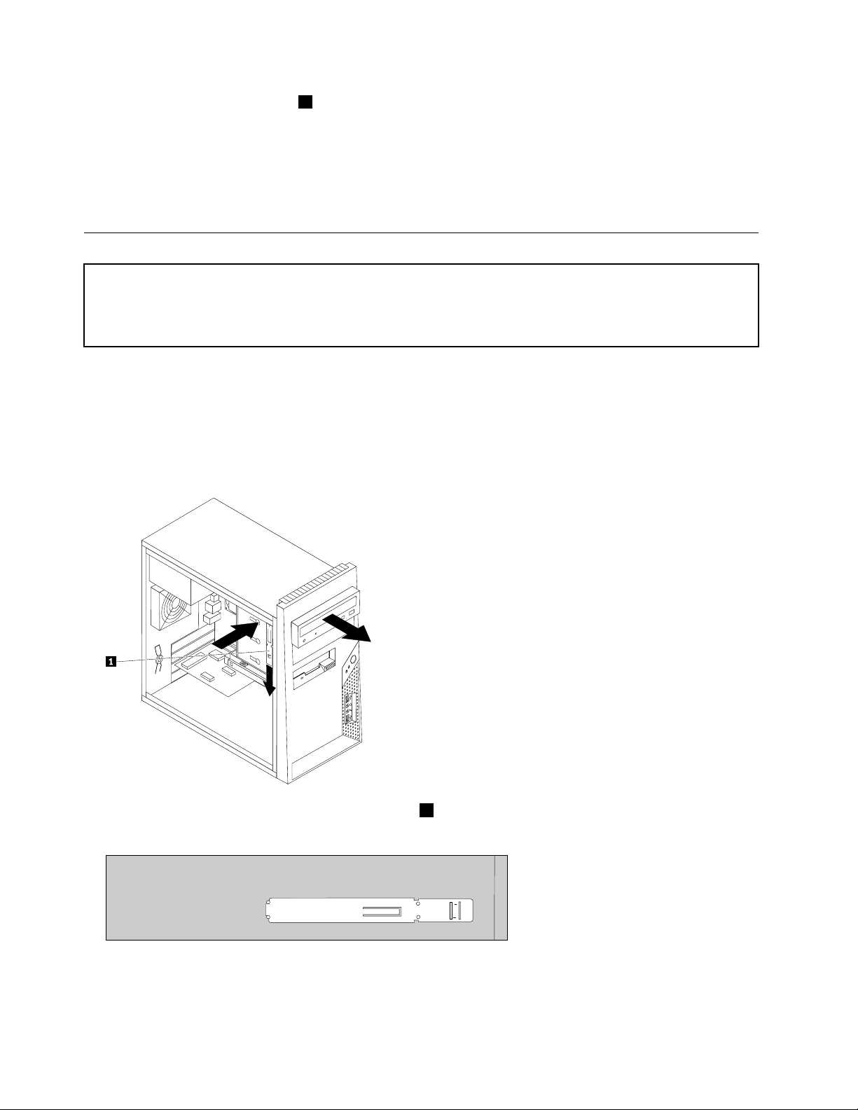
10.Pressdownonthemetallatch2andpivotinthedrivecageintoplace.Slideitforwarduntilitsnaps
intoposition.
Note:Therearetwoarrows,oneontheupperdrivecageandoneontheharddiskdrivecage,thatare
alignedwhentheharddiskdriveisintheproperposition.
11.Connectthepowerandsignalcablestotheharddiskdrive.
12.Goto"CompletingtheFRUreplacement"onpage91.
Replacinganopticaldrive
Attention
Donotopenyourcomputerorattemptanyrepairbeforereadingandunderstandingthe"Importantsafetyinformation"
intheThinkCentreSafetyandWarrantyGuidethatcamewithyourcomputer.T oobtainacopyoftheThinkCentre
SafetyandWarrantyGuide,goto:http://www.lenovo.com/support
Thissectionprovidesinformationonhowtoremoveandreplaceanopticaldrive.
Toremoveandreplacetheopticaldrive,dothefollowing;
1.Removethecomputercover.See"Removingthecover"onpage68.
2.Disconnectthesignalandpowercablesfromtherearoftheopticaldrive.
3.Pressthereleasebuttonandremovetheopticaldriveoutthefrontofthecomputer.
Note:Noticethatthereisaspareretainerbracket1attachedtotheupperdrivecage.
4.Removetheretainerbracketfromthedrivebeingreplacedandinstallitonthenewdrive.
5.Slidethenewopticaldriveintothebayfromthefrontuntilitsnapsintoposition.
6.Connectthesignalandpowercablestothedrive.
7.Goto"CompletingtheFRUreplacement"onpage91.
84ThinkCentreHardwareMaintenanceManual
Page 91
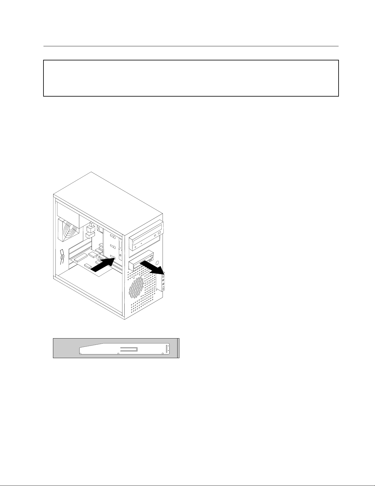
Replacingthediskettedrive
Attention
Donotopenyourcomputerorattemptanyrepairbeforereadingandunderstandingthe"Importantsafetyinformation"
intheThinkCentreSafetyandWarrantyGuidethatcamewithyourcomputer.T oobtainacopyoftheThinkCentre
SafetyandWarrantyGuide,goto:http://www.lenovo.com/support
Thisprocedureprovidesinformationonhowtoremoveandreplacethediskettedrive.
Toremoveorreplacethediskettedrive,dothefollowing:
1.Removethecomputercover.See"Removingthecover"onpage68.
2.Removethefrontbezel.See"Removingandreplacingthefrontbezel"onpage71.
3.Disconnectthesignalandpowercablesfromtherearofthediskettedrive.
4.Pressthereleasebuttonandslidethediskettedriveoutthefrontofthecomputer.
5.Removetheretainerbracketfromthefailingdiskettedriveandinstallitonthenewdiskettedrive.
6.Slidethenewdiskettedriveintothedrivebayuntilitsnapsintoposition.
7.Connectthesignalandpowercablestothedrive.
8.Goto"CompletingtheFRUreplacement"onpage91.
Chapter8ReplacingFRUs(T ypes7061,7090,9353,9421,9485,9623,9625,9705,9786,9795,9935,9946,9953)85
Page 92
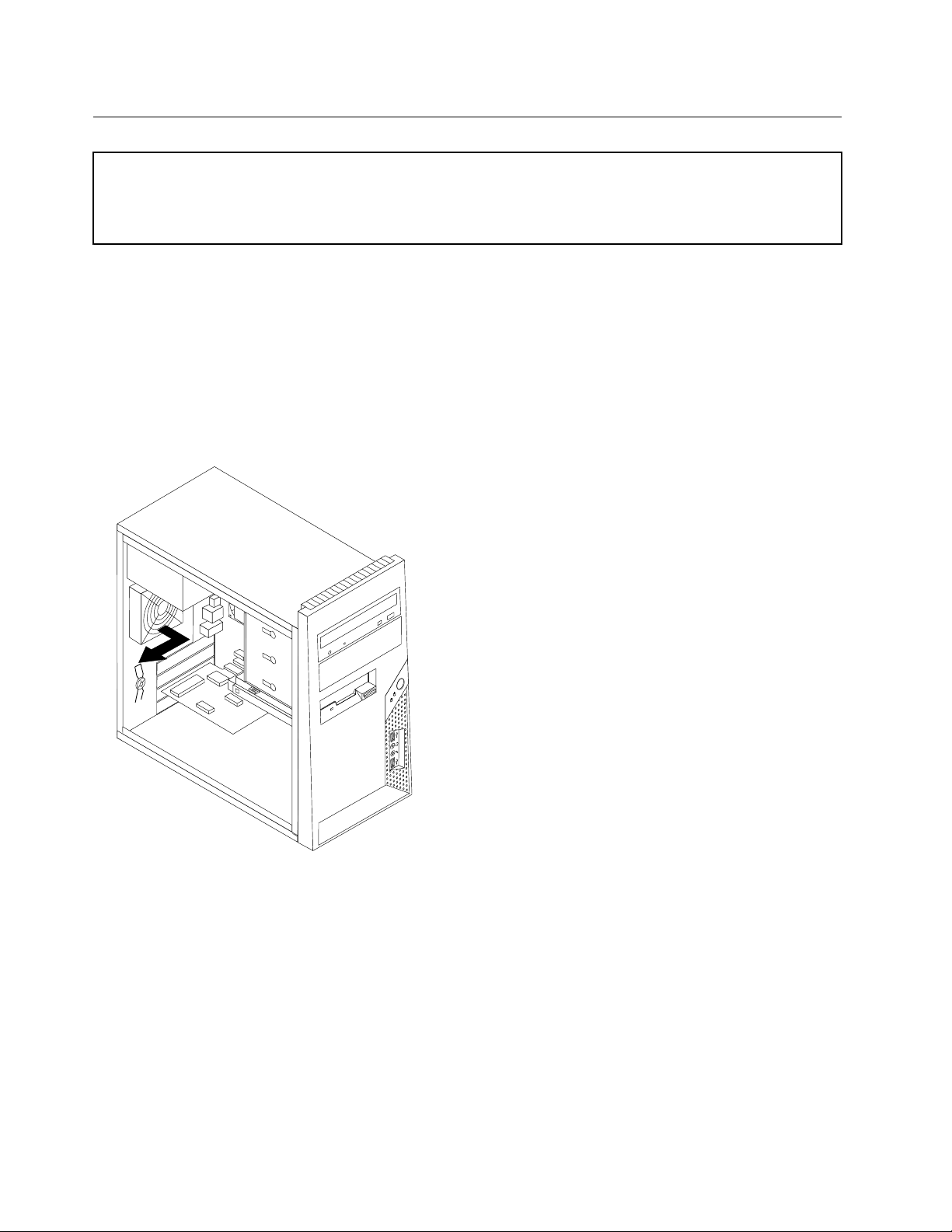
Replacingtherearfanassembly
Attention
Donotopenyourcomputerorattemptanyrepairbeforereadingandunderstandingthe"Importantsafetyinformation"
intheThinkCentreSafetyandWarrantyGuidethatcamewithyourcomputer.T oobtainacopyoftheThinkCentre
SafetyandWarrantyGuide,goto:http://www.lenovo.com/support
Thissectionprovidesinformationonhowtoremoveandreplacethesystemfan.
Toremoveorreplacethesystemfan,dothefollowing:
1.Removethecomputercover.See"Removingthecover"onpage68.
2.Locatetherearfanassembly.Disconnecttherearfancablefromthesystemfanconnectoronthesystem
board.See"Locatingpartsonthesystemboard"onpage71
3.Therearfanassemblyismountedwithfourrubbermountsthatprotrudethroughtherearofthechassis.
Removethefanassemblybypullingtherubbermountsbackthroughthechassis.
.
4.Installthenewrearfanassemblybyaligningtherubbermountsofthesystemfanassemblywiththe
holesonthechassisandpushtherubbermountsthroughtheholes.
5.Pullonthetipsoftherubbermountsuntilthefanassemblyisinplace.
86ThinkCentreHardwareMaintenanceManual
Page 93
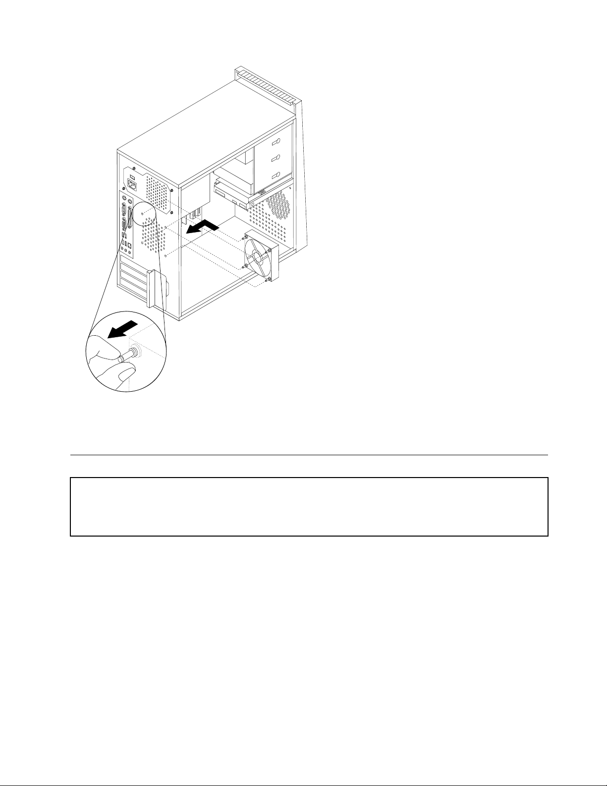
6.Routethefancabletothesystemboardandconnectthecabletothesystemboard.See"Locating
partsonthesystemboard"onpage71.
7.Goto"CompletingtheFRUreplacement"onpage91.
Replacingthefrontfanassembly
Attention
Donotopenyourcomputerorattemptanyrepairbeforereadingandunderstandingthe"Importantsafetyinformation"
intheThinkCentreSafetyandWarrantyGuidethatcamewithyourcomputer.T oobtainacopyoftheThinkCentre
SafetyandWarrantyGuide,goto:http://www.lenovo.com/support
Thissectionprovidesinformationonhowtoremoveandreplacethefrontfanassembly.
Toremoveorreplacethefrontfanassembly,dothefollowing:
1.Removethecomputercover.See"Removingthecover"onpage68.
2.Removethefrontbezel.See"Removingandreplacingthefrontbezel"onpage71.
3.Disconnectthefrontfanassemblycablefromthepowerfanconnectoronthesystemboard.See
"Locatingpartsonthesystemboard"onpage71
4.Thefrontfanassemblyisattachedtothechassisbyfourrubbermounts.Removethefrontfanassembly
bygentlypullingitoutofthechassis.
.
Chapter8ReplacingFRUs(T ypes7061,7090,9353,9421,9485,9623,9625,9705,9786,9795,9935,9946,9953)87
Page 94
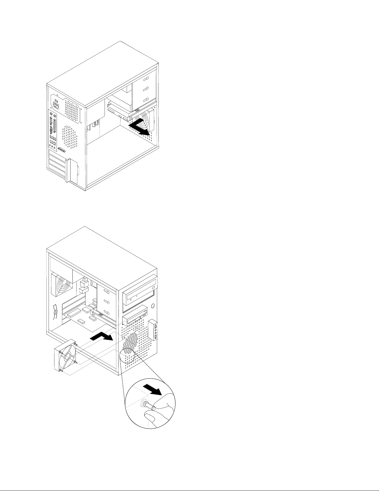
5.Installthenewfrontfanassemblybyaligningtherubbermountsofthefrontfanassemblywiththeholes
onthechassisandpushtherubbermountsthroughtheholes.
6.Pullonthetipsoftherubbermountsuntilthefanassemblyisinplace.
7.Routethefancabletothesystemboardandconnectthecabletothesystemboard.See"Locating
partsonthesystemboard"onpage71.
88ThinkCentreHardwareMaintenanceManual
Page 95
8.Replacethefrontbezel.
9.Goto"CompletingtheFRUreplacement"onpage113.
Replacingthefrontaudio/USBassembly
Attention
Donotopenyourcomputerorattemptanyrepairbeforereadingandunderstandingthe"Importantsafetyinformation"
intheThinkCentreSafetyandWarrantyGuidethatcamewithyourcomputer.T oobtainacopyoftheThinkCentre
SafetyandWarrantyGuide,goto:http://www.lenovo.com/support
Thissectionprovidesinformationonhowtoremoveandreplacethefrontaudio/USBassembly.
Toremoveorreplacethefrontaudio/USBassembly,dothefollowing:
1.Removethecomputercover.See"Removingthecover"onpage68.
2.Removethefrontbezel.See"Removingandreplacingthefrontbezel"onpage71
3.Disconnectthefrontaudio/USBassemblycablefromthesystemboard.See"Locatingpartsonthe
systemboard"onpage71.
4.Notethefrontaudio/USBassemblycableroutingandremovethescrewthatsecurestheassemblyto
thechassis.
5.Removethefrontaudio/USBassembly.
6.Routethecableforthenewfrontaudio/USBassemblythroughtheholeinthechassisandtothesystem
board.
7.Installthefrontaudio/USBassemblyintothechassisandsecureitwiththescrew.
8.Connectthefrontaudio/USBassemblycabletothesystemboard.
9.Reinstallthefrontbezel.
10.Goto"CompletingtheFRUreplacement"onpage91.
Replacingthepowerswitch/LEDassembly
Attention
Donotopenyourcomputerorattemptanyrepairbeforereadingandunderstandingthe"Importantsafetyinformation"
intheThinkCentreSafetyandWarrantyGuidethatcamewithyourcomputer.T oobtainacopyoftheThinkCentre
SafetyandWarrantyGuide,goto:http://www.lenovo.com/support
Thissectionprovidesinformationonhowtoremoveandreplacethepowerswitch/LEDassembly.
Toremoveorreplacethepowerswitch/LEDassembly,dothefollowing:
1.Removethecomputercover.See"Removingthecover"onpage68.
2.Removethefrontbezel.See"Removingandreplacingthefrontbezel"onpage71
3.Disconnectthepowerswitch/LEDassemblycablefromthesystemboard.See"Locatingpartsonthe
systemboard"onpage71.
4.Notethepowerswitch/LEDassemblycableroutingandthepositionofthetwoLEDs.
5.RemovetheswitchandtheLEDsfromthebezel.
6.Routethecableforthenewpowerswitch/LEDassemblythroughtheholeinthechassisandtothe
systemboard.
7.Installthenewpowerswitch/LEDassemblyintothebezel.MakesurethattheLEDsareinthecorrect
position.
8.Connectthepowerswitch/LEDcabletothesystemboard.
Chapter8ReplacingFRUs(T ypes7061,7090,9353,9421,9485,9623,9625,9705,9786,9795,9935,9946,9953)89
Page 96
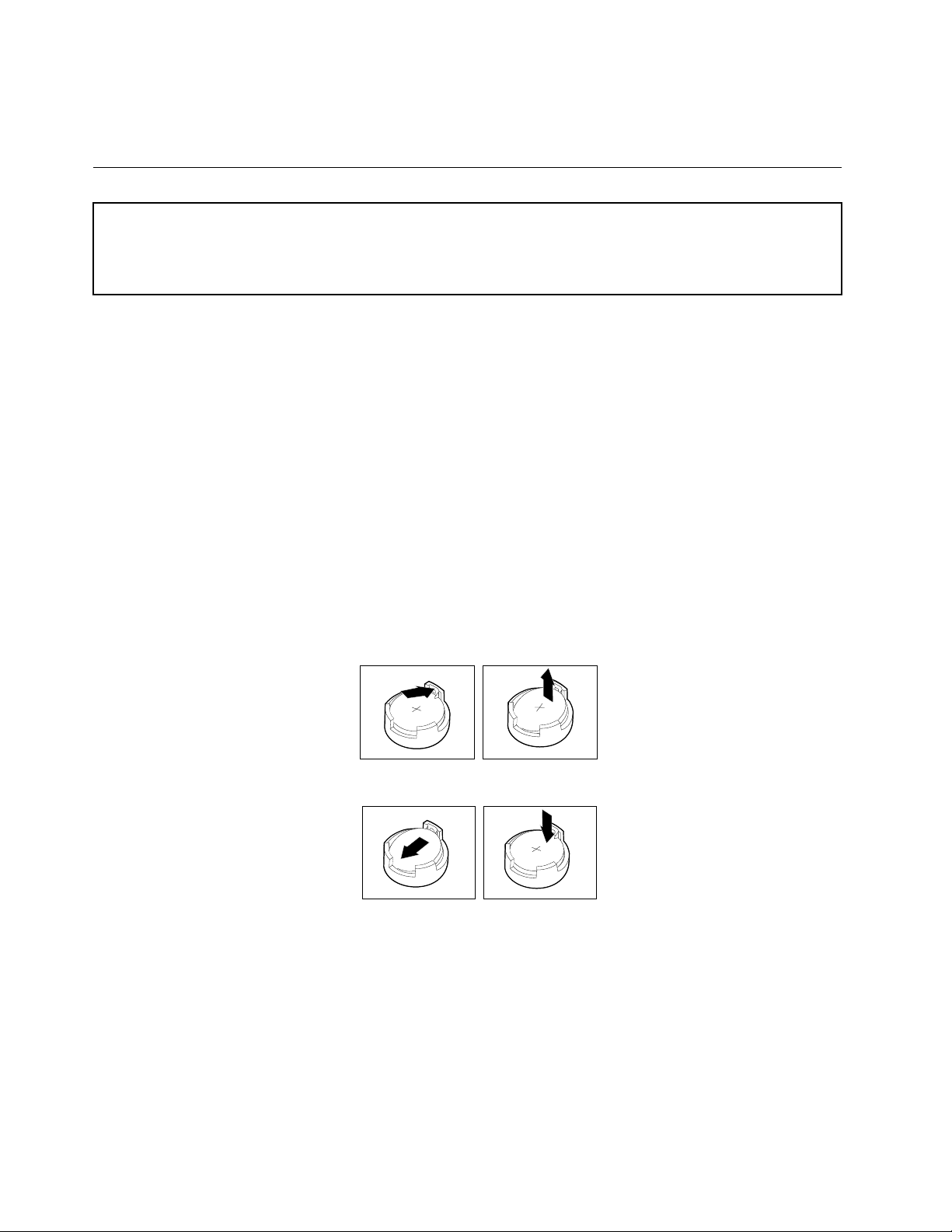
9.Reinstallthefrontbezel.
10.Goto"CompletingtheFRUreplacement"onpage91.
ReplacingtheCMOSbattery
Attention
Donotopenyourcomputerorattemptanyrepairbeforereadingandunderstandingthe"Importantsafetyinformation"
intheThinkCentreSafetyandWarrantyGuidethatcamewithyourcomputer.T oobtainacopyoftheThinkCentre
SafetyandWarrantyGuide,goto:http://www.lenovo.com/support
ThissectionprovidesinformationonhowtoremoveandreplacetheCMOSbattery.
ToremoveorreplacetheCMOSbattery,dothefollowing:
IftheCMOSbatteryfails,thedate,time,andcongurationinformation(includingpasswords)arelost.An
errormessageisdisplayedwhenyouturnonthecomputer.
Important
Referto"Safetynotices(multi-lingualtranslations)"onpage6forinformationaboutreplacinganddisposing
ofthebattery.
CAUTION:
Whenreplacingthelithiumbattery,useonlyPartNumber33F8354oranequivalenttypebattery
recommendedbythemanufacturer.
1.Removethecomputercover.See"Removingthecover"onpage68.
2.Locatethebattery.See"Locatingpartsonthesystemboard"onpage71.
3.Removetheoldbattery.
4.Installthenewbattery.
5.Replacethecomputercover,andconnectthecables.
Note:Whenthecomputeristurnedonforthersttimeafterbatteryreplacement,anerrormessage
mightbedisplayed.Thisisnormalafterreplacingthebattery.
6.T urnonthecomputerandallattacheddevices.
7.UsetheSetupUtilityprogramtosetthedateandtimeandanypasswords.See"UsingtheSetup
Utility"intheUserGuide.
90ThinkCentreHardwareMaintenanceManual
Page 97

CompletingtheFRUreplacement
AfterreplacingFRUs,youneedtoinstallanyremovedparts,replacethecover,andreconnectanycables,
includingtelephonelinesandpowercords.Also,dependingontheFRUthatisreplaced,youmightneedto
conrmtheupdatedinformationintheSetupUtilityprogram.
Note:Whenthepowercordisrstpluggedin,thecomputermightappeartoturnonforafewsecondsand
thenturnoff.Thisisanormalsequencetoenablethecomputertoinitialize.
1.Ensurethatallcomponentshavebeenreassembledcorrectlyandthatnotoolsorloosescrewsareleft
insideyourcomputer.
2.Replacethecover.
3.Reconnecttheexternalcablesandpowercordstothecomputer.See"Rearconnectors"onpage67.
4.Ifyouhavereplacedthesystemboard,youmustupdate(ash)theBIOS.See"Flashupdateprocedures"
onpage467.
5.SomeFRUreplacementsrequirethecongurationtobeupdated.SeeChapter6"UsingtheSetup
Utility"onpage39.
Chapter8ReplacingFRUs(T ypes7061,7090,9353,9421,9485,9623,9625,9705,9786,9795,9935,9946,9953)91
Page 98

92ThinkCentreHardwareMaintenanceManual
Page 99
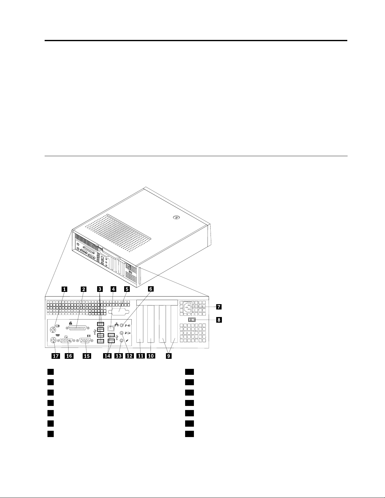
Chapter9.ReplacingFRUs(Types7057,7062,7092,9342,
9344,9354,9426,9486,9624,9707,9787,9804,9945)
Important
BeforeyoureplaceanyFRU,readChapter2"Safetyinformation"onpage3.Theseprecautionsand
guidelineswillhelpyouworksafely.
FRUreplacementsaretobedonebytrainedservicetechniciansonly.
ThischapterdoesnotcontainaremoveandreplaceprocedureforallFRUs.OnlythemajorFRUsare
documented.
Rearconnectors
Thefollowingillustrationshowsthelocationsoftheconnectorsontherearofthecomputer.
1
Standardmouseconnector
2
Parallelconnector
3
USBconnectors(4)
4
Ethernetconnector
5
Serialconnector(somemodels)
6
Audiolineinconnector
7
Powercordconnector
©CopyrightLenovo2008,2010
10
11
12
13
14
15
16
PCIExpress16xadapterconnector
PCIExpressx1adapterconnector
Audiolineoutconnector
Microphoneconnector
USBconnectors(2)
VGAmonitorconnector
DVImonitorconnector
93
Page 100
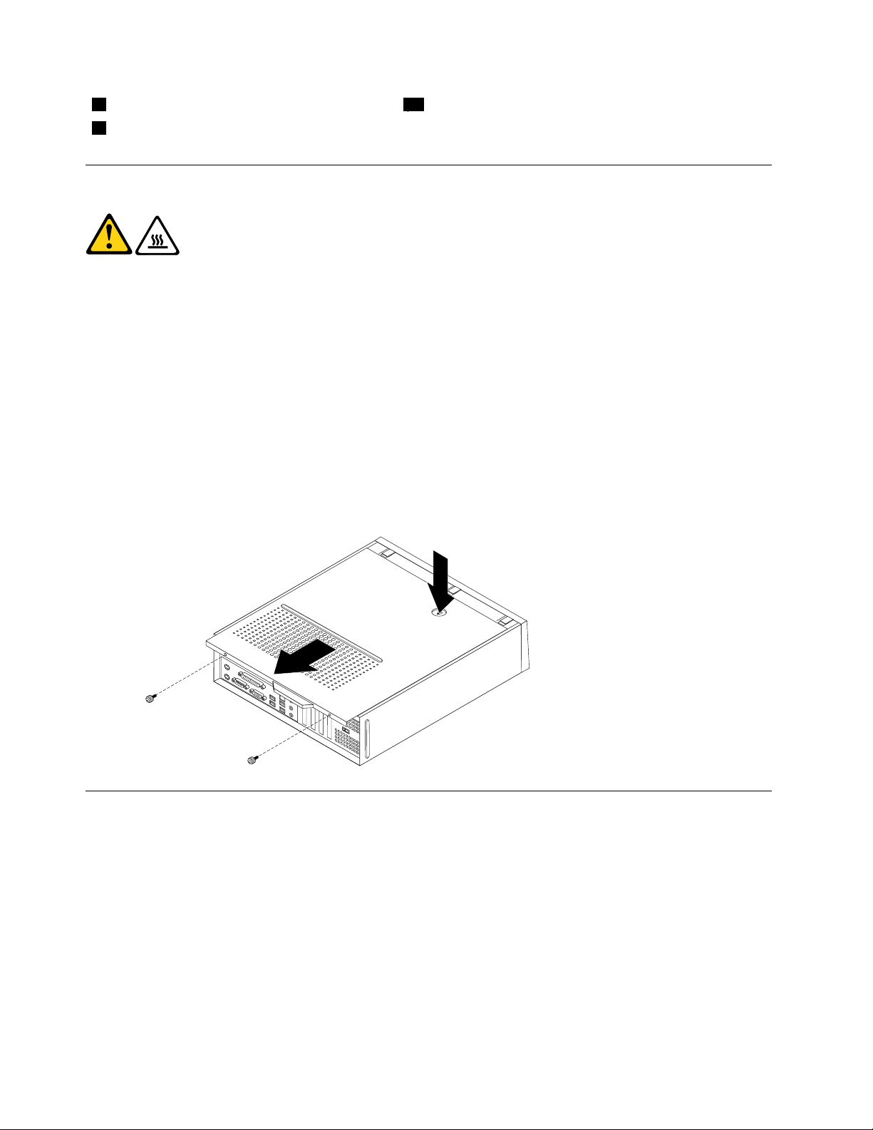
8
Voltage-selectionswitch(somemodels)
9
PCIadapterconnectors(2)
17
Standardkeyboardconnector
Removingthecover
CAUTION:
Theheatsinkandmicroprocessormightbeveryhot.Turnoffthecomputerandwait
threetoveminutestoletthecomputercoolbeforeopeningthecomputercover.
Thissectionprovidesinformationonhowtoremovethecover.
Toremoveorreplacethecover,dothefollowing:
1.Removeanymedia(diskettes,CDs,ortapes)fromthedrives,shutdowntheoperatingsystem,and
turnoffallattacheddevices.
2.Unplugallpowercordsfromelectricaloutlets.
3.Disconnectallcablesattachedtothecomputer.Thisincludespowercords,input/output(I/O)cables,
andanyothercablesthatareconnectedtothecomputer.
4.Removeanylockingdevicessuchasapadlockthatsecurethecover.
5.Ifthecoverissecuredwiththumbscrews,removethem.
6.Pressthebuttonnearthefrontofthecomputercoverandslidethecovertotherear,andremoveit.If
yourcomputerhasscrewstosecurethecomputercover,removethescrews,andthenremovethecover.
Locations
ThefollowingillustrationwillhelpyoulocatethemajorFRUsinthecomputer.
94ThinkCentreHardwareMaintenanceManual
 Loading...