

Lenovo 5468, 7X58 Setup Manual

ThinkSystem SD650 Dual Node DWC Tray and
NeXtScale n1200 DWC Enclosure
Setup Guide
Machine Type: 7X58 and 5468

Note
Before using this information and the product it supports, be sure to read and understand the safety
information and the safety instructions, which are available at:
http://thinksystem.lenovofiles.com/help/topic/safety_documentation/pdf_files.html
http://systemx.lenovofiles.com/help/topic/com.lenovo.sysx.safety.doc/safety_pdf.pdf
The server is intended for use in a system/rack always installed on the load side of Power Distribution Unit
(PDU) or Uninterruptible Power Supply (UPS) supplying a maximum 20 A branch circuit protection. The
overall system/rack connection to mains power is to be a Pluggable Type B connector.
In addition, be sure that you are familiar with the terms and conditions of the Lenovo warranty for your
solution, which can be found at:
http://datacentersupport.lenovo.com/warrantylookup
Third Edition (October 2018)
© Copyright Lenovo 2018.
LIMITED AND RESTRICTED RIGHTS NOTICE: If data or software is delivered pursuant to a General Services
Administration (GSA) contract, use, reproduction, or disclosure is subject to restrictions set forth in Contract No.
GS-35F-05925.

Contents
Chapter 1. Introduction . . . . . . . . . 1
Solution package contents . . . . . . . . . . . 1
Features. . . . . . . . . . . . . . . . . . . 1
Specifications . . . . . . . . . . . . . . . . 3
Upgrade existing NeXtScale nx360 M5 to
ThinkSystem SD650 . . . . . . . . . . . . 7
Management options. . . . . . . . . . . . . . 7
Chapter 2. Solution components . . . 15
Front view . . . . . . . . . . . . . . . . . 17
Enclosure . . . . . . . . . . . . . . . 17
Tray . . . . . . . . . . . . . . . . . 17
Rear view . . . . . . . . . . . . . . . . . 18
Fan power control (FPC) module . . . . . . 19
Power supplies . . . . . . . . . . . . . 19
Internal cable routing. . . . . . . . . . . . . 21
2.5-inch drive models. . . . . . . . . . . 21
Internal Faceplate Transition (IFT) adapter . . . 21
Parts list. . . . . . . . . . . . . . . . . . 22
Power cords . . . . . . . . . . . . . . 27
Chapter 3. Solution hardware
setup . . . . . . . . . . . . . . . . . . 29
Solution setup checklist . . . . . . . . . . . 29
Installation Guidelines . . . . . . . . . . . . 30
System reliability guidelines . . . . . . . . 31
Working inside the solution with the power
on . . . . . . . . . . . . . . . . . . 31
Handling static-sensitive devices . . . . . . 32
Install solution hardware options . . . . . . . . 32
Remove a DWC tray from the enclosure . . . 32
Remove the tray cover . . . . . . . . . . 34
Remove a DIMM. . . . . . . . . . . . . 34
Remove a drive . . . . . . . . . . . . . 37
Remove the M.2 backplane . . . . . . . . 39
Remove an adapter . . . . . . . . . . . 40
Remove an Internal Faceplate Transition (IFT)
adapter . . . . . . . . . . . . . . . . 42
Memory module installation . . . . . . . . 44
Install an M.2 drive into the M.2 backplane . . 51
Install the M.2 backplane . . . . . . . . . 54
Install a drive . . . . . . . . . . . . . . 55
Install an adapter . . . . . . . . . . . . 57
Install an Internal Faceplate Transition (IFT)
adapter . . . . . . . . . . . . . . . . 59
Install the tray cover . . . . . . . . . . . 61
Install a DWC tray in the enclosure. . . . . . 63
Install the enclosure in a rack . . . . . . . . . 64
Cable the enclosure . . . . . . . . . . . . . 64
Power on nodes . . . . . . . . . . . . . . 64
Power off nodes . . . . . . . . . . . . . . 65
Chapter 4. System configuration . . . 67
Set the network connection for the Lenovo XClarity
Controller . . . . . . . . . . . . . . . . . 67
Update the firmware . . . . . . . . . . . . . 68
Configure the firmware . . . . . . . . . . . . 71
Memory configuration . . . . . . . . . . . . 71
RAID configuration . . . . . . . . . . . . . 72
Install the operating system . . . . . . . . . . 72
Back up the solution configuration . . . . . . . 73
Chapter 5. Resolving installation
issues . . . . . . . . . . . . . . . . . 75
Appendix A. Getting help and
technical assistance . . . . . . . . . . 79
Before you call . . . . . . . . . . . . . . . 79
Collecting service data . . . . . . . . . . . . 80
Contacting Support . . . . . . . . . . . . . 81
Index . . . . . . . . . . . . . . . . . . 83
© Copyright Lenovo 2018 i

ii ThinkSystem SD650 Dual Node DWC Tray and NeXtScale n1200 DWC Enclosure Setup Guide
Chapter 1. Introduction
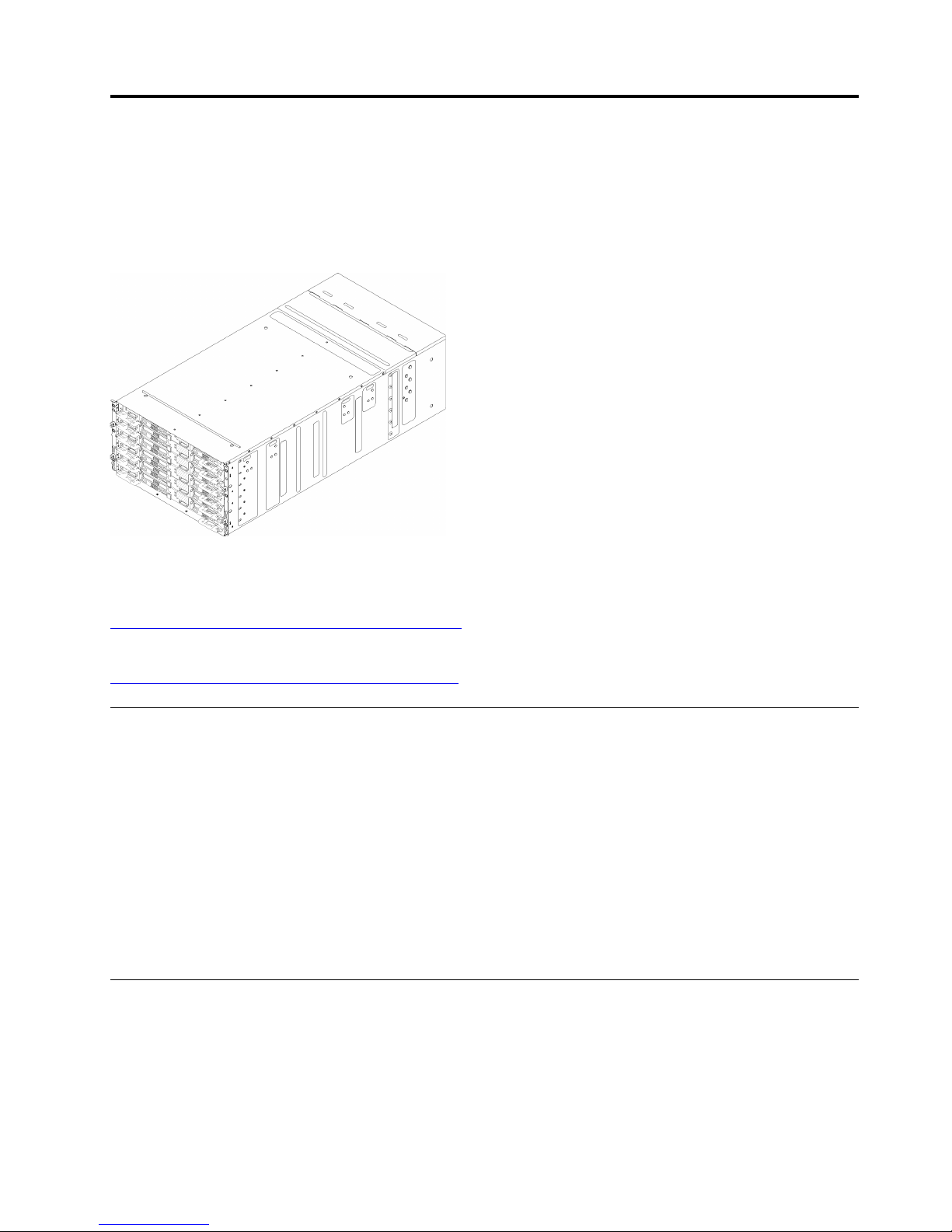
The ThinkSystem SD650 Dual Node DWC Tray and NeXtScale n1200 DWC Enclosure is a 6U solution
designed for high-volume network transaction processing. This solution includes a single enclosure that can
contain up to six ThinkSystem SD650 trays, which are designed to deliver a dense, scalable platform for
distributed enterprise and hyperconverged solutions.
Figure 1. Enclosure with six ThinkSystem SD650 trays installed
The solution comes with a limited warranty. For details about the warranty, see:
https://support.lenovo.com/us/en/solutions/ht503310
For details about your specific warranty, see:
http://datacentersupport.lenovo.com/warrantylookup
Solution package contents
When you receive your solution, verify that the shipment contains everything that you expected to receive.
The solution package includes the following items:
Note: Some of the items listed are available on select models only.
• DWC tray
• Enclosure
• Rail installation kit (optional). Detailed instructions for installing the rail installation kit are provided in the
package with the rail installation kit.
• Material box, including items such as power cords, rack installation template, and accessory kit.
Features
Performance, ease of use, reliability, and expansion capabilities were key considerations in the design of
your solution. These design features make it possible for you to customize the system hardware to meet your
needs today and provide flexible expansion capabilities for the future.
Your solution implements the following features and technologies:
© Copyright Lenovo 2018 1

• Features on Demand
If a Features on Demand feature is integrated in the solution or in an optional device that is installed in the
solution, you can purchase an activation key to activate the feature. For information about Features on
Demand, see:
https://fod.lenovo.com/lkms
• Lenovo XClarity Controller (XCC)
The Lenovo XClarity Controller is the common management controller for Lenovo ThinkSystem solution
hardware. The Lenovo XClarity Controller consolidates multiple management functions in a single chip on
the node system board.
Some of the features that are unique to the Lenovo XClarity Controller are enhanced performance, higherresolution remote video, and expanded security options. For additional information about the Lenovo
XClarity Controller, see:
http://sysmgt.lenovofiles.com/help/topic/com.lenovo.systems.management.xcc.doc/product_page.html
• UEFI-compliant server firmware
Lenovo ThinkSystem firmware is Unified Extensible Firmware Interface (UEFI) 2.5 compliant. UEFI
replaces BIOS and defines a standard interface between the operating system, platform firmware, and
external devices.
Lenovo ThinkSystem solutions are capable of booting UEFI-compliant operating systems, BIOS-based
operating systems, and BIOS-based adapters as well as UEFI-compliant adapters.
Note: The solution does not support DOS (Disk Operating System).
• Active Memory
The Active Memory feature improves the reliability of memory through memory mirroring. Memory
mirroring mode replicates and stores data on two pairs of DIMMs within two channels simultaneously. If a
failure occurs, the memory controller switches from the primary pair of memory DIMMs to the backup pair
of DIMMs.
• Large system-memory capacity
The solution supports synchronous dynamic random-access memory (SDRAM) registered dual inline
memory modules (DIMMs) with error correcting code (ECC). For more information about the specific types
and maximum amount of memory, see “Specifications” on page 3.
• Integrated network support
The tray comes with an integrated 1-port Gigabit Ethernet controller with RJ-45 connector, which
supports connection to a 1000 Mbps network.
• Integrated Trusted Platform Module (TPM)
This integrated security chip performs cryptographic functions and stores private and public secure keys.
It provides the hardware support for the Trusted Computing Group (TCG) specification. You can
download the software to support the TCG specification.
Trusted Platform Module (TPM) has two versions - TPM 1.2 and TPM 2.0. You can change the TPM
version from 1.2 to 2.0 and back again.
For more information on TPM configurations, see “Enable TPM/TCM” in the Maintenance Manual.
Note: For customers in the People’s Republic of China, a Lenovo-qualified TPM 2.0 adapter or a Trusted
Cryptographic Module (TCM) adapter (sometimes called a daughter card) may be pre-installed.
• Large data-storage capacity
The simple-swap solution models support the following drives:
– Supports up to four 2.5-inch simple-swap Serial ATA (SATA) hard disk drives per tray
– Supports up to two 2.5-inch simple-swap Serial ATA (SATA) NVMe solid-state drives per tray
2
ThinkSystem SD650 Dual Node DWC Tray and NeXtScale n1200 DWC Enclosure Setup Guide

• Light path diagnostics
Light path diagnostics provides LEDs to help you diagnose problems. For more information about the light
path diagnostics, see Light path diagnostics panel and Light path diagnostics LEDs.
• Mobile access to Lenovo Service Information website
The solution provides a QR code on the system service label, which is on the cover of the solution, that
you can scan using a QR code reader and scanner with a mobile device to get quick access to the Lenovo
Service Information website. The Lenovo Service Information website provides additional information for
parts installation, replacement videos, and error codes for solution support.
• Active Energy Manager
Lenovo XClarity Energy Manager is a power and temperature management solution for data centers. You
can monitor and manage the power consumption and temperature of Converged, NeXtScale, System x,
ThinkServer solutions and ThinkServer servers, and improve energy efficiency using Lenovo XClarity
Energy Manager.
• Optional power capabilities
The solution supports a maximum of six 1300-watt, 1500-watt or 2000-watt hot-swap power supplies.
Note: You cannot mix 1300-watt, 1500-watt and 2000-watt power supplies in the solution.
• ThinkSystem RAID support
The ThinkSystem RAID provides software RAID supports for RAID levels 0 and 1 while integrated onboard hardware RAID supports for RAID levels 1.
Specifications
The following information is a summary of the features and specifications of the solution. Depending on the
model, some features might not be available, or some specifications might not apply.
Enclosure specifications
Table 1. Enclosure specifications
Specification
Power supply
Fan power control (FPC)
module
Size 6U enclosure
Description
Supports six hot-swap ac power supplies
• 1300-watt ac
• 1500-watt ac
• 2000-watt ac
Important: Power supplies and redundant power supplies in the enclosure must be
with the same power rating, wattage or efficiency Level .
• Hot-swappable
• Height: 263.3 mm (10.37 inches)
• Depth: 914.5 mm (36 inches)
• Width: 447 mm (17.6 inches)
• Weight:
– Fully configured (stand-alone): approximately 135.5 kg (298 lbs)
– Empty enclosure (with midplane, FPC, and cables): approximately 25 kg (55 lbs)
Chapter 1. Introduction 3

Table 1. Enclosure specifications (continued)
Specification
Acoustical noise emissions Note: The following readings are worst case for the air cooling. The water cooling
Heat output Approximate heat output:
Electrical input
Water requirement
Description
results would be significantly less.
• Operation: 7.0 bels
• Idle: 6.5 bels
• Minimum configuration (with one minimal configuration tray): 433 BTU per hour
(127 watts)
• Maximum configuration (with six maximal configuration trays): 40946 BTU per
hour (12000 watts)
• Sine-wave input (50-60 Hz) required
• Input voltage range:
– Minimum: 200 V AC
– Maximum: 240 V AC
• Minimum water flow rate: 6.0 liters per minute per enclosure, assuming 1.0 lpm
per compute tray with 6 trays per enclosure (1 tray consists of 2 compute nodes)
– For processors below 205 W: 6.0 liters per minute per enclosure, assuming 1.0
lpm per compute tray with 6 trays per enclosure (1 tray consists of 2 compute
nodes)
• Maximum pressure: 4.4 bars
Note: The water required to initially fill the system side cooling loop must be
reasonably clean, bacteria- free water (<100 CFU/ml) such as de-mineralized water,
reverse osmosis water, de-ionized water, or distilled water. The water must be
filtered with an in-line 50 micron filter (approximately 288 mesh). The water must be
treated with anti-biological and anti-corrosion measures.
4 ThinkSystem SD650 Dual Node DWC Tray and NeXtScale n1200 DWC Enclosure Setup Guide

Tray specifications
Table 2. Tray specifications
Specification Description
Size Tray
• Height: 41.0 mm (1.6 inches)
• Depth: 742.0 mm (29.2 inches)
• Width: 438.0 mm (17.25 inches)
• Weight estimation: 17.2 kg (38 lb)
Environment The SD650 tray complies with ASHRAE class A2 specifications.
The SD650 tray is supported in the following environment:
• Water Temperature:
– Operating: ASHRAE class W4: 2 - 45°C (35.6 - 113°F)
• Air temperature:
– Operating: ASHRAE class A2: 10 - 35°C (50 - 95°F); when the altitude exceeds
900 m (2953 ft), the maximum ambient temperature value decreases by 1°C
(1.8°F) with every 300 m (984 ft) of altitude increase.
– Solution off: 5 - 45°C (41 - 113°F)
– Shipping/storage: -40 - 60°C (-40 - 140°F)
• Maximum altitude: 3048 m (10 000 ft)
• Relative Humidity (non-condensing):
– Operating:
– ASHRAE Class A2: 8% - 80%, maximum dew point : 21°C (70°F)
– Shipment/storage: 8% - 90%
• Particulate contamination:
Airborne particulates and reactive gases acting alone or in combination with other
environmental factors such as humidity or temperature might pose a risk to the
solution. For information about the limits for particulates and gases, see
Particulate contamination .
Chapter 1. Introduction 5

Node specifications
Table 3. Node specifications
Specification Description
Processor (depending on the
model)
Memory
Drive bays
• Supports up to two Intel Xeon series multi-core processors per node (1 tray
consists of 2 nodes)
• Level-3 cache
Notes:
1. Use the Setup utility to determine the type and speed of the processors in the
node.
2. For a list of supported processors, see
serverproven/
3. With certain processors installed, if UEFI Boot Mode is set to Legacy then PXE
Boot from the onboard Gigabit Ethernet port may not work as expected and is
not supported. The affected processors are all processors with embedded Omni
Path fabric. These are processors models that have an F at the end of the model
name and include (but not limited to) the following processor models:
• Intel Xeon Gold 6126F Processor
• Intel Xeon Gold 6130F Processor
• Intel Xeon Gold 6138F Processor
• Intel Xeon Gold 6142F Processor
• Intel Xeon Gold 6148F Processor
• Intel Xeon Platinum 8160F Processor
• Intel Xeon Platinum 8176F Processor
• Slots: 12 DIMM slots per node (1 tray consists of 2 nodes)
• Minimum: 8 GB (single DDR4 DIMM per processor)
• Maximum: 768 GB
– 384 GB (12 x 32GB RDIMM)
– 768 GB (12 x 64GB LRDIMM)
• Type:
– PC4-21300 (dual-rank), 2666 MT/s, error correcting code (ECC), double-data-
rate 4 (DDR4) registered DIMM (RDIMM) or load reduced DIMM (LRDIMM)
• Supports (depending on the model):
– 8 GB, 16 GB, and 32 GB size DIMMs
– 64 GB LRDIMM
Supports up to two 2.5-inch simple-swap SATA/NVMe drive bays per node (1 tray
consists of 2 nodes).
Attention: As a general consideration, do not mix standard 512-byte and advanced
4-KB format drives in the same RAID array because it might lead to potential
performance issues.
Supports the following 2.5-inch simple-swap drive:
• Two 2.5-inch 7mm SATA solid-state drives per node (1 tray consists of 2 nodes)
• One 2.5-inch 15mm SATA/NVMe hard disk drive/solid-state drive per node (1 tray
consists of 2 nodes)
.
http://www.lenovo.com/us/en/
6 ThinkSystem SD650 Dual Node DWC Tray and NeXtScale n1200 DWC Enclosure Setup Guide

Table 3. Node specifications (continued)
Specification
M.2 drive/backplane ThinkSystem M.2 with Mirroring Enablement Kit contains dual M.2 backplane
RAID
Video controller (integrated
into Lenovo XClarity
Controller)
Input/Output (I/O) features
Description
supports up to two identical M.2 drives.
Supports 2 different physical sizes of M.2 drives:
• 42 mm (2242)
• 80 mm (2280)
See “Install an M.2 drive into the M.2 backplane” on page 51for supported M.2 drive
configurations.
• Software RAID supports for RAID levels 0 and 1 for SATA storages
• Integrated on-board Hardware RAID supports for RAID levels 1 for M.2 SSD
• ASPEED
• SVGA compatible video controller
• Avocent Digital Video Compression
• Video memory is not expandable
Note: Maximum video resolution is 1920 x 1200 at 60 Hz.
• Front panel
• KVM breakout cable connector
• One STD USB 3.0 connector with Intel DCI feature
• One 1GbE Ethernet connector with share-NIC feature for Lenovo XClarity
Controller access
• One 1GbE Ethernet connector dedicated for Lenovo XClarity Controller access
Minimum configuration for
debugging
• One n1200 Enclosure
• One SD650 Dual Node DWC Tray (contains two computer nodes)
• One processor on location 1 on specific node
• One CFF v2 power supply (any type)
• One DIMM (any type) on specific node
• One disk (any type) (If OS is needed for debugging)
Upgrade existing NeXtScale nx360 M5 to ThinkSystem SD650
The following enclosure requirements are mandatory if you are upgrading existing NeXtScale nx360 M5 to
ThinkSystem SD650.
Attention: Only Lenovo Professional Service - Data Center Services is allowed to perform the upgrading
task.
• Update all firmware to the latest level
• Flow rate only needs to be adjusted if 205 W processors installed. If 205 W processors installed, increase
the water flow rate to 1.25 liters per minute per tray.
Management options
Several management interfaces are available for managing your server. The management options described
in this section are provided to support the direct management of Lenovo servers.
Chapter 1. Introduction 7

Function
Lenovo
XClarity
Administrator
Lenovo
XClarity
Integrator
Lenovo
XClarity
Energy
Manager
Lenovo
XClarity
Provisioning
Manager
Lenovo
XClarity
Essen-
1
tials
Lenovo
XClarity
Controller
Lenovo
Capacity
Planner
Lenovo
Business
Vantage
Fan and
Power
Control
Multiple
systems
management
Operating
system
deployment
Firmware
updates
2
System
configuration
Events /
alerts
Inventory /
Log
Power
management
Data
center
planning
√ √ √ √
√ √
√ √ √
3
√ √ √
√ √ √ √ √
√ √ √ √ √
√ √ √
5
√
√ √
4
√ √ √
√
Security
6
√
management
Notes:
1. Lenovo XClarity Essentials includes Lenovo XClarity Essentials OneCLI, Lenovo XClarity Essentials
Bootable Media Creator, and Lenovo XClarity Essentials UpdateXpress.
2. Most options can be updated through the Lenovo tools. Some options, such as GPU firmware or OmniPath firmware require the use of vendor tools.
3. Firmware updates are limited to Lenovo XClarity Provisioning Manager, Lenovo XClarity Controller
firmware, and UEFI updates only. Firmware updates for optional devices, such as adapters, are not
supported.
4. The server UEFI settings for option ROM must be set to Auto or UEFI to update firmware using Lenovo
XClarity Administrator or Lenovo XClarity Essentials.
5. The server UEFI settings for option ROM must be set to Auto or UEFI for detailed adapter card
information, such as model name and firmware levels, to be displayed in Lenovo XClarity Administrator,
Lenovo XClarity Controller, or Lenovo XClarity Essentials.
6. Limited inventory.
7. Power management function is supported by Lenovo XClarity Integrator for VMware vCenter.
8. Available only in the People’s Republic of China.
8
ThinkSystem SD650 Dual Node DWC Tray and NeXtScale n1200 DWC Enclosure Setup Guide

Lenovo XClarity Administrator
Lenovo XClarity Administrator is a centralized, resource-management solution that simplifies infrastructure
management, speeds responses, and enhances the availability of Lenovo server systems and solutions. It
runs as a virtual appliance that automates discovery, inventory, tracking, monitoring, and provisioning for
server, network, and storage hardware in a secure environment.
Lenovo XClarity Administrator provides a central interface to perform the following functions for all managed
endpoints:
• Manage and monitor hardware. Lenovo XClarity Administrator provides agent-free hardware
management. It can automatically discover manageable endpoints, including server, network, and storage
hardware. Inventory data is collected for managed endpoints for an at-a-glance view of the managed
hardware inventory and status.
• Configuration management. You can quickly provision and pre-provision all of your servers using a
consistent configuration. Configuration settings (such as local storage, I/O adapters, boot settings,
firmware, ports, and Lenovo XClarity Controller and UEFI settings) are saved as a server pattern that can
be applied to one or more managed servers. When the server patterns are updated, the changes are
automatically deployed to the applied servers.
• Firmware compliance and updates. Firmware management is simplified by assigning firmware-
compliance policies to managed endpoints. When you create and assign a compliance policy to managed
endpoints, Lenovo XClarity Administrator monitors changes to the inventory for those endpoints and flags
any endpoints that are out of compliance.
When an endpoint is out of compliance, you can use Lenovo XClarity Administrator to apply and activate
firmware updates for all devices in that endpoint from a repository of firmware updates that you manage.
• Operating System deployment. You can use Lenovo XClarity Administrator to manage a repository of
operating-system images and to deploy operating-system images to up to 28 managed servers
concurrently.
• Service and support. Lenovo XClarity Administrator can be set up to collect and send diagnostic files
automatically to your preferred service provider when certain serviceable events occur in Lenovo XClarity
Administrator and the managed endpoints. You can choose to send diagnostic files to Lenovo Support
using Call Home or to another service provider using SFTP. You can also manually collect diagnostic files,
open a problem record, and send diagnostic files to the Lenovo Support Center.
Lenovo XClarity Administrator can be integrated into external, higher-level management and automation
platforms through open REST application programming interfaces (APIs). Using the REST APIs, Lenovo
XClarity Administrator can easily integrate with your existing management infrastructure. In addition, you can
automate tasks using the PowerShell toolkit or the Python toolkit.
To obtain the latest version of the Lenovo XClarity Administrator, see:
https://datacentersupport.lenovo.com/documents/LNVO-LXCAUPD
Documentation for Lenovo XClarity Administrator is available at:
http://sysmgt.lenovofiles.com/help/topic/com.lenovo.lxca.doc/aug_product_page.html
Lenovo XClarity Integrator
Lenovo also provides the following integrators that you can use to manage Lenovo servers from higher-level
management tools:
• Lenovo XClarity Integrator for VMware vCenter
• Lenovo XClarity Integrator Microsoft System Center
For more information about Lenovo XClarity Integrator, see:
http://www3.lenovo.com/us/en/data-center/software/systems-management/xclarity-integrators
Chapter 1. Introduction 9

Lenovo XClarity Energy Manager
Lenovo XClarity Energy Manager is a web-based power and temperature management solution designed for
data center administrators. It monitors and manages the power consumption and temperature of servers,
such as Converged, NeXtScale, System x, ThinkServer, and ThinkSystem servers, using the out-of-band
method. Lenovo XClarity Energy Manager models data center physical hierarchy and monitors power and
temperature at the server/group level. By analyzing monitored power and temperature data, Lenovo XClarity
Energy Manager greatly improves business continuity and energy efficiency.
With Lenovo XClarity Energy Manager, administrators can take control of power usage through improved
data analysis and lower the TCO (total cost of ownership). The tool optimizes data center efficiency by
allowing administrators to:
• Monitor energy consumption, estimate power need, and re-allocate power to servers as needed via IPMI
or Redfish.
• Track platform power consumption, inlet temperature, and component-level power consumption, such as
CPU and memory power consumption.
• Visually check the layout of room, row and rack via 2D thermal map.
• Show events and send e-mail or SNMP trap notifications when certain faults occur or certain thresholds
are reached.
• Limit the consumed amount of energy of an endpoint by setting up policies.
• Optimize energy efficiency by identifying hotspot or over-cooling servers to optimize cooling efficiency
and identifying low-usage servers to save energy.
• Reduce the power consumption to the minimum level to prolong service time during emergency power
event (such as a data-center power failure).
For more information about downloading, installation, and usage, see:
https://datacentersupport.lenovo.com/solutions/lnvo-lxem
Lenovo XClarity Provisioning Manager
Lenovo XClarity Provisioning Manager is embedded software that provides a graphic user interface (GUI) for
configuring the system with support for 10 languages. It simplifies the process of configuring Basic Input
Output System (BIOS) settings and configuring Redundant Array of Independent Disks (RAID) in a GUI
wizard. It also provides functions for updating applications and firmware, performing system diagnostics,
and automating the process of installing the supported Windows, Linux, or VMware ESXi operating systems
and associated device drivers.
Note: When you start a server and press F1, the Lenovo XClarity Provisioning Manager interface is displayed
by default. However, the text-based interface to system configuration (the Setup Utility) is also available.
From Lenovo XClarity Provisioning Manager, you can choose to restart the server and access the text-based
interface. In addition, you can choose to make the text-based interface the default interface that is displayed
when you press F1.
Lenovo XClarity Provisioning Manager provides a system summary of all installed devices and includes the
following functions:
• UEFI setup. Use this function to configure UEFI system settings, such as processor configuration, start
options, and user security. You can also view POST events and the System Event Log (SEL).
• Firmware update. Use this function to update the firmware for Lenovo XClarity Controller, Unified
Extensible Firmware Interface (UEFI), Lenovo XClarity Provisioning Manager, and operating system device
drivers.
10
ThinkSystem SD650 Dual Node DWC Tray and NeXtScale n1200 DWC Enclosure Setup Guide

• RAID setup. Use this function to configure RAID for the server. It provides an easy-to-use graphical
wizard that supports a unified process for performing RAID setup for a variety of RAID adapters. You can
also perform advanced RAID configuration from the UEFI Setup.
• OS installation. Use this function to deploy an operating system for the server with an easy-to-use
Guided Install mode. Operating systems can be installed using unattended mode after you choose the
Operating System version and basic settings; the device drivers are installed automatically.
A Manual Install mode is also available. You can export the drivers from system, manually install the
operating systems, and then install the drivers. This way, you do not need to go to the web to download
device drivers.
Note: In Guided Install mode, you can export the operating system installation settings to a response file
during operating system installation. Then, you can use the Import function under the Cloning menu to
apply the operating system installation settings to the target server.
• Cloning. Use this function to clone settings in one server to other similarly configured Lenovo servers.
– Export: Export UEFI, RAID, and BMC settings for the current server to files respectively and save the
files to a USB storage drive or a shared network folder.
– Import: Apply UEFI, RAID, BMC, and operating system installation settings to the target server by
using the files you have saved.
• Diagnostics. Use this function to view the overall health of devices installed in the server, collect logs for
RAID adapters, and perform diagnostics for hard disk drives and memory. You can also collect service
data that can be saved to a USB device and sent to Lenovo Support.
Note: The service data collected by Lenovo XClarity Provisioning Manager does not include the operating
system logs. To collect the operating system logs and the hardware service data, use Lenovo XClarity
Essentials OneCLI.
Documentation for Lenovo XClarity Provisioning Manager is available at:
http://sysmgt.lenovofiles.com/help/topic/LXPM/LXPM_introduction.html
Lenovo XClarity Essentials
Lenovo XClarity Essentials (LXCE) is a collection of server management utilities that provides a less
complicated method to enable customers to manage Lenovo ThinkSystem, System x, and Thinkserver
servers more efficiently and cost-effectively.
Lenovo XClarity Essentials includes the following utilities:
• Lenovo XClarity Essentials OneCLI is a collection of several command line applications, which can be
used to:
– Configure the server.
– Collect service data for the server. If you run Lenovo XClarity Essentials OneCLI from the server
operating system (in-band), you can collect operating system logs as well. You can also choose to view
the service data that has been collected or to send the service data to Lenovo Support.
– Update firmware and device drivers for the server. Lenovo XClarity Essentials OneCLI can help to
download UpdateXpress System Packs (UXSPs) for your server and update all the firmware and device
drivers payloads within the UXSP.
– Perform miscellaneous functions, such as rebooting the server or rebooting the BMC.
To learn more about Lenovo XClarity Essentials OneCLI, see:
https://datacentersupport.lenovo.com/documents/LNVO-CENTER
Documentation for Lenovo XClarity Essentials OneCLI is available at:
Chapter 1. Introduction 11

http://sysmgt.lenovofiles.com/help/topic/xclarity_essentials/overview.html
• Lenovo XClarity Essentials Bootable Media Creator (BoMC) is a software application that applies
UpdateXpress System Packs and individual updates to your system.
Using Lenovo XClarity Essentials Bootable Media Creator, you can:
– Update the server using an ISO image or CD.
– Update the server using a USB key.
– Update the server using the Preboot Execution Environment (PXE) interface.
– Update the server in unattendance mode.
– Update the server in Serial Over LAN (SOL) mode.
To learn more about Lenovo XClarity Essentials Bootable Media Creator, see:
https://datacentersupport.lenovo.com/solutions/lnvo-bomc
• Lenovo XClarity Essentials UpdateXpress is a software application that applies UpdateXpress System
Packs and individual updates to your system.
Using Lenovo XClarity Essentials UpdateXpress, you can:
– Update the local server.
– Update a remove server.
– Create a repository of updates.
To learn more about Lenovo XClarity Essentials UpdateXpress, see:
https://datacentersupport.lenovo.com/solutions/lnvo-xpress
Lenovo XClarity Controller
Lenovo XClarity Controller is the management processor for the server. It is the third generation of the
Integrated Management Module (IMM) service processor that consolidates the service processor
functionality, super I/O, video controller, and remote presence capabilities into a single chip on the server
system board.
There are two ways to access the management processor:
• Web-based interface. To access the web-based interface, point your browser to the IP address for the
management processor.
• Command-line interface. To access the CLI interface, use SSH or Telnet to log in to the management
processor.
Whenever power is applied to a server, the management processor is available. From the management
processor interface, you can perform the following functions:
• Monitor all hardware devices installed in the server.
• Power the server on and off.
• View the system event log and system audit log for the server.
• Use the Remote management function to log in to the server itself.
Documentation for Lenovo XClarity Controller is available at:
http://sysmgt.lenovofiles.com/help/topic/com.lenovo.systems.management.xcc.doc/product_page.html
Lenovo Capacity Planner
Lenovo Capacity Planner is a power consumption evaluation tool that enhances data center planning by
enabling IT administrators and pre-sales to understand important parameters of different type of racks,
12
ThinkSystem SD650 Dual Node DWC Tray and NeXtScale n1200 DWC Enclosure Setup Guide

servers, and other devices. Lenovo Capacity Planner can dynamically calculate the power consumption,
current, British Thermal Unit (BTU), and volt-ampere (VA) rating at the rack level, and therefore improves the
efficiency of large scale deployments.
Lenovo Capacity Planner provides the following functions:
• Power and thermal evaluation of servers and network devices; generating evaluation reports.
• Customizable server configuration, workload, CPU turbo model, and fan speed for different user
scenarios.
• Chassis-level and node-level customizable configuration for Flex System and High-Density servers.
• Visual memory configuration guidance for best memory performance.
More information about Lenovo Capacity Planner is available at:
https://datacentersupport.lenovo.com/solutions/lnvo-lcp
Lenovo Business Vantage
Lenovo Business Vantage is a security software tool suite designed to work with the Trusted Cryptographic
Module (TCM) adapter for enhanced security, to keep user data safe, and to erase confidential data
completely from a hard disk drive.
Lenovo Business Vantage provides the following functions:
• Data Safe. Encrypt files to ensure data safety by using the TCM adapter.
• Sure Erase. Erase confidential data from a hard disk. This tool follows the industry standard method to do
the erasing and allows the user to select different erasing levels.
• Smart USB Protection. Prohibit unauthorized access to the USB port of devices.
• USB Data Safe. Encrypt files to ensure data security on a USB storage device.
Note: This tool is available in the People’s Republic of China only.
More information about Lenovo Business Vantage is available at:
http://support.lenovo.com.cn/lenovo/wsi/es/es.html
Fan and Power Control
FPC is a hot-swap enclosure management module that helps you to easily manage the system power bank
and fan speed. It provides the fan, power and enclosure status with event logs.
Documentation for FPC is available at:
http://thinksystem.lenovofiles.com/help/index.jsp.
Chapter 1. Introduction 13

14 ThinkSystem SD650 Dual Node DWC Tray and NeXtScale n1200 DWC Enclosure Setup Guide
Chapter 2. Solution components
Use the information in this section to learn about each of the components associated with your solution.
Identifying your component
When you contact Lenovo for help, the machine type, model, and serial number information helps support
technicians to identify your components and provide faster service.
The enclosure machine type, model number and serial number are on the enclosure label that can be found
on the front of the enclosure, as shown in the following illustration.
Figure 2. Enclosure label on the front of the enclosure
Table 4. Enclosure label on the front of the enclosure
1 Enclosure label
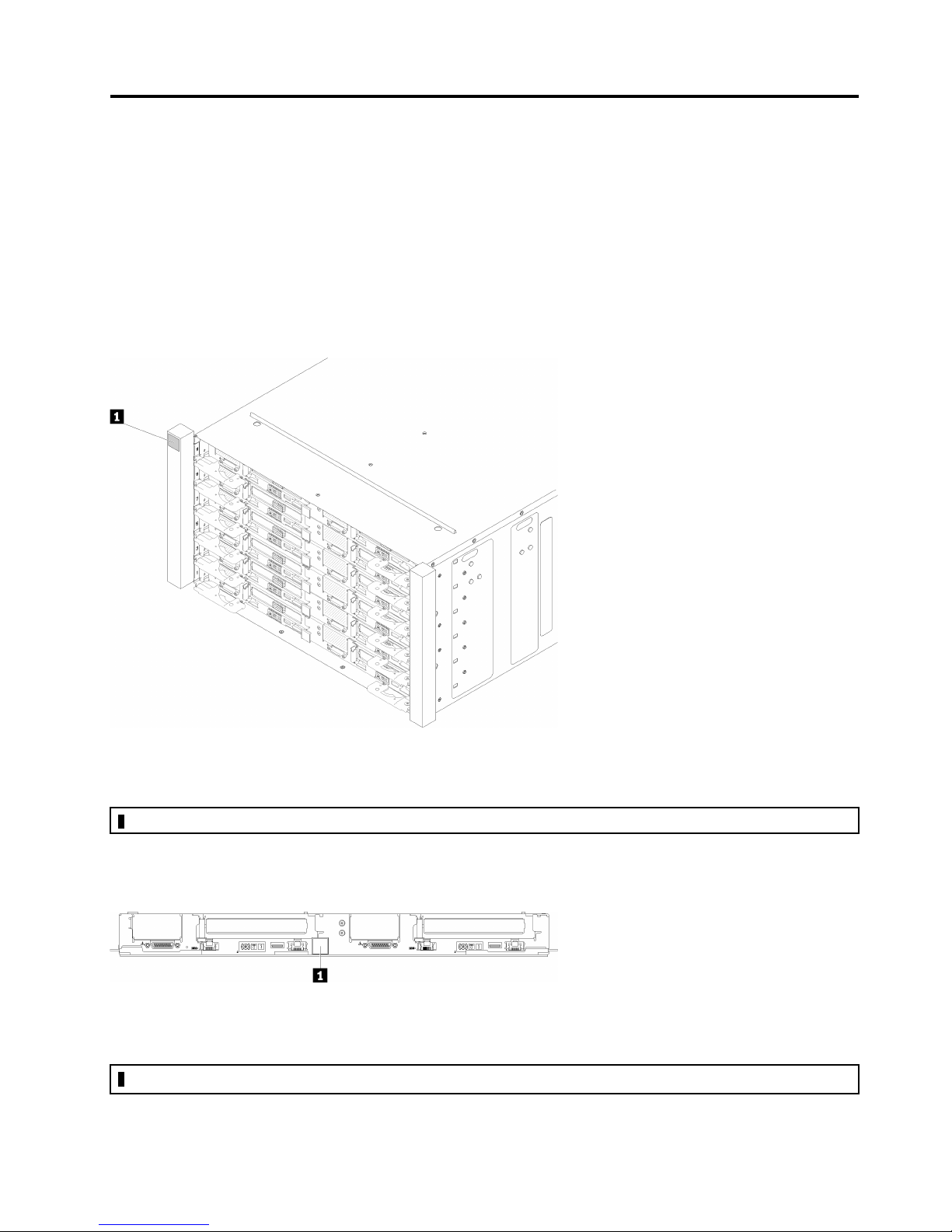
The tray machine type, model number and serial number are on the tray label that can be found on the front
of the tray, as shown in the following illustration.
Figure 3. Tray label on the front of the tray
Table 5. Tray label on the front of the tray
1 Tray label
© Copyright Lenovo 2018 15
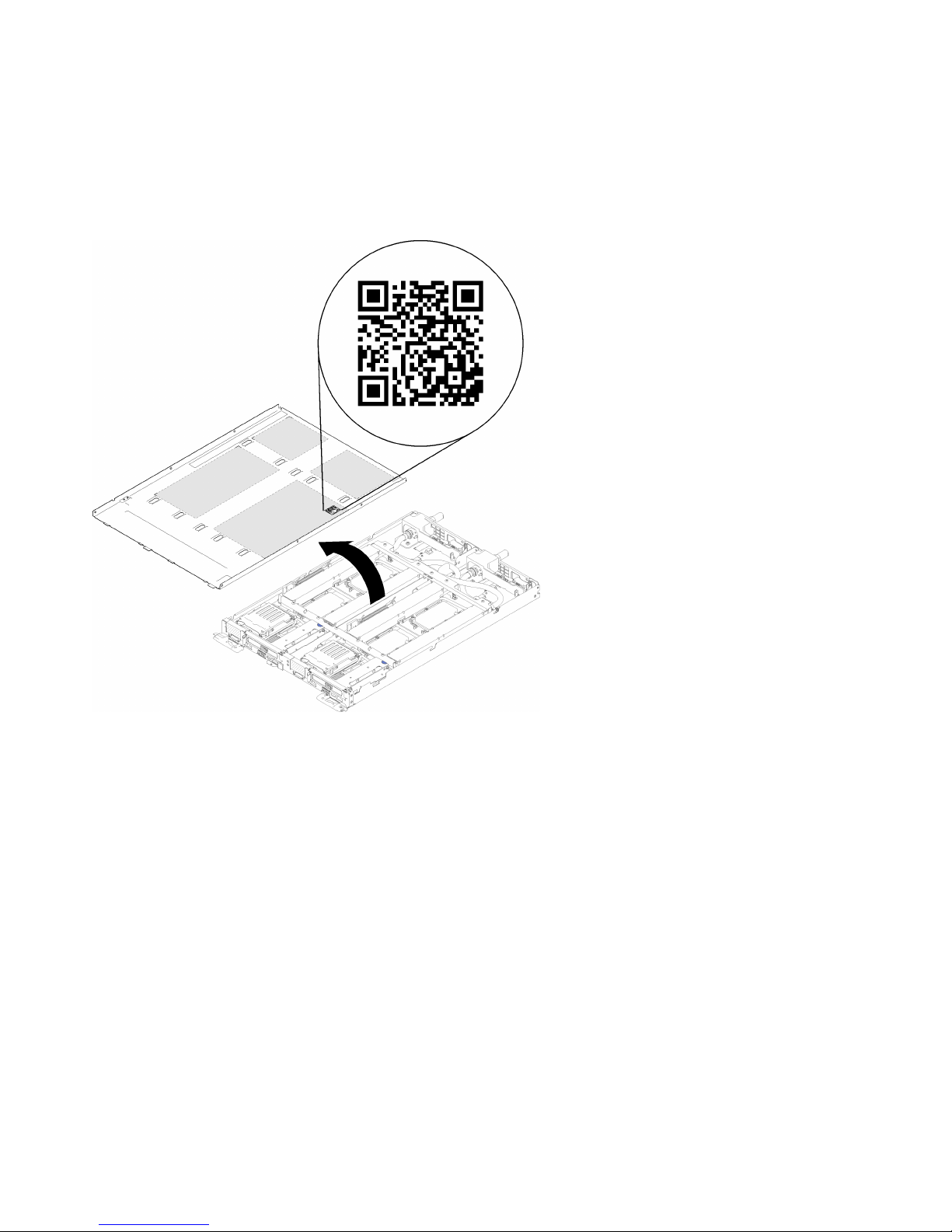
QR code
In addition, the system Service Label is located on the inside surface of the tray cover, provides a quick
reference (QR) code for mobile access to service information. You can scan the QR code with a mobile
device using a QR code reader application and get quick access to the Service Information web page. The
Service Information web page provides additional information for parts installation and replacement videos,
and error codes for solution support.
Figure 4. Service Label and QR code
Network access tag
The Lenovo XClarity Controller network access information for both nodes can be found on the pull out
information tag located at the front of the tray. You can use the information on the pull out tag to access the
XCC MAC address and LLA for each node. The left node information is on the left side and the right node
information is on the right side. You can also use the information tag for your own node labeling information
such as the hostname, the system name and the inventory bar code.
16
ThinkSystem SD650 Dual Node DWC Tray and NeXtScale n1200 DWC Enclosure Setup Guide
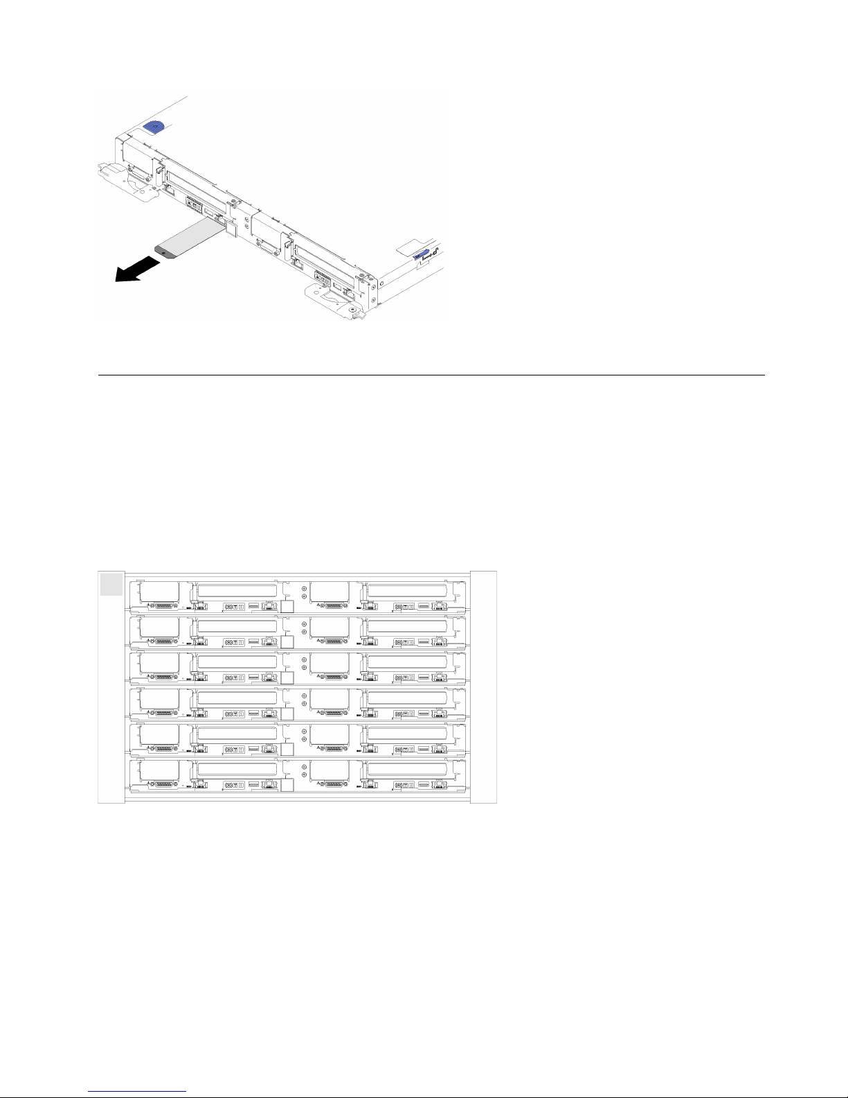
Figure 5. Network access information on the pull out tag
Front view
The following illustration shows the controls, LEDs, and connectors on the front of the solution.
Enclosure
Note: The illustrations in this document might differ slightly from your hardware.
The enclosure supports up to six trays.
The following illustration shows six trays installed in the enclosure.
Figure 6. Enclosure
Tray
The following illustrations show the controls, LEDs, and connectors on the front of each tray.
Chapter 2. Solution components 17
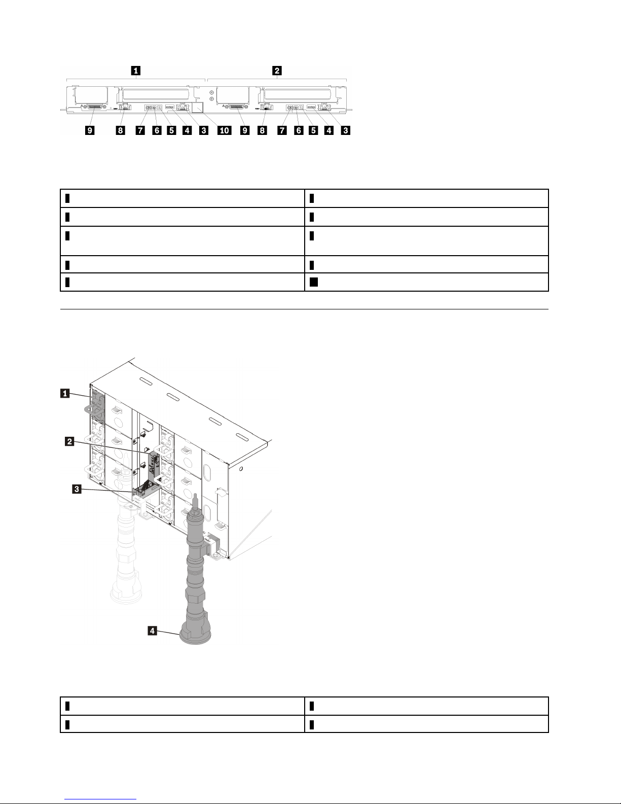
Figure 7. Tray
Table 6. Tray indicators, controls, and connectors
1 Left node (odd bay numbers)
2 Right node (even bay numbers) 7 Power button/LED
3 Dedicated LAN RJ45 port for Lenovo XClarity Controller
access
4 USB 3.0 connector
5 System error LED
6 Identification LED
8 Ethernet RJ45 port with share-NIC feature to access
Lenovo XClarity Controller
9 KVM breakout cable connector
10 Tray label
Rear view
The following illustration shows the components on the rear of the enclosure.
Figure 8. Rear view
Table 7. Rear view
1 Power supply 3 Drip sensor assembly
2 Fan and Power Control
18 ThinkSystem SD650 Dual Node DWC Tray and NeXtScale n1200 DWC Enclosure Setup Guide
4 Manifold
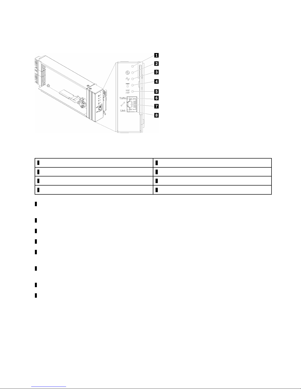
Fan power control (FPC) module
The following illustration shows the connectors and LEDs on the FPC module.
Figure 9. FPC connectors and LEDs
Table 8. FPC connectors and LEDs
1 Reset button hole
2 Power LED (green) 6 Ethernet port activity (RJ-45) LED (green)
3 Activity LED (green) 7 Dedicated Ethernet port for FPC management access
4 Identification LED (blue) 8 Ethernet port link (RJ-45) LED (green)
1 Reset button: Press the button for 1 to 4 seconds, FPC reboots. Press over 4 seconds, FPC reboots and
5 Check log LED (yellow)
loads to the default settings.
2 Power-on LED: When this LED is lit (green), it indicates that the FPC has power.
3 Activity LED: When this LED is lit (green), it indicates that the FPC is actively controlling the enclosure.
4 Identification LED: When this LED is lit (blue), it indicates the enclosure location in a rack.
5 Check log LED: When this LED is lit (yellow), it indicates that a system error has occurred. Check the FPC
event log for additional information.
6 Ethernet port activity (RJ-45) LED: When this LED is flashing (green), it indicates that there is activity
through the remote management and console (Ethernet) port over the management network.
7 Dedicated Ethernet port for FPC management access: Use this connector to access FPC management.
8 Ethernet port link (RJ-45) LED: When this LED is lit (green), it indicates that there is an active connection
through the remote management and console (Ethernet) port to the management network.
Power supplies
The NeXtScale n1200 DWC Enclosure Type 5468 supports six autoranging power supplies.
The power supplies get electrical power from a 200 - 240 V ac power source and convert the ac input into 12
V outputs. The power supplies are capable of autoranging within the input voltage range. There is one
common power domain for the enclosure that distributes power to each of the DWC tray and modules
through the system midplane.
Chapter 2. Solution components 19

AC redundancy is achieved by distributing the ac power cord connections between independent ac circuits.
Each power supply has internal fans and a controller. The power supply controller can be powered by any
installed power supply that is providing power through the midplane.
Attention: The power supplies contain internal cooling fans. Do not obstruct the fan exhaust vents.
You have to install all of the six power supplies regardless of the type of power supply, the enclosure power
load, or selected enclosurepower policy.
The NeXtScale n1200 DWC Enclosure Type 5468 does not support mixing of low input voltage power
supplies with high input voltage power supplies. For example, if you install a power supply with an input
voltage of 100 - 127 V ac in a enclosure that is powered by 200 - 240 V ac power supplies, the 100 - 127 V
power supply will not power on. The same restriction applies to a enclosure that is powered by 100 - 127 V
ac power supplies. If you install a 200 - 240 V ac power supply in a enclosure that is powered by 100 - 127 V
ac power supplies, the 200 - 240 V ac power supply will not power on.
The following illustration shows the power supply:
Figure 10. Power supply LEDs and connectors
1 Input (AC) power LED (green) 3 Power supply error LED (yellow)
2 Output (DC) power LED (green)
There are three LEDs on each power supply:
1 AC power LED (green): When this LED is lit (green), it indicates that ac power is being supplied to the
power supply.
2 DC power LED (green): When this LED is lit (green), it indicates that dc power is being supplied from the
power supply to the enclosure midplane.
20
ThinkSystem SD650 Dual Node DWC Tray and NeXtScale n1200 DWC Enclosure Setup Guide
3 Power supply error LED (yellow): When this LED is lit (yellow), it indicates that there is a fault with the
power supply.
Note: Before unplugging the ac power cord from the power supply, or removing the power supply from the
enclosure, verify that the capacity of the remaining power supplies are sufficient to meet the minimum power
requirements for all components in the enclosure.
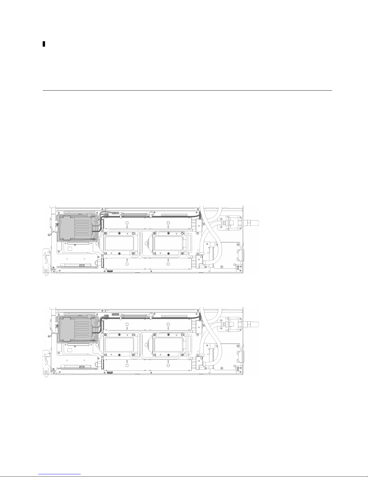
Internal cable routing
Some of the components in the solution have internal cables and cable connectors.
Note: Disengage all latches, release tabs, or locks on cable connectors when you disconnect cables from
the system board. Failing to release them before removing the cables will damage the cable sockets on the
system board, which are fragile. Any damage to the cable sockets might require replacing the system board.
Some options, such as IFT processors, might require additional internal cabling. See the documentation that
is provided for the option to determine any additional cabling requirements and instructions.
2.5-inch drive models
The following illustrations show the cable routing for 2.5-inch drive models.
1x2.5-inch drive model
Figure 11. Cable routing - 1x2.5-inch drive model
2x2.5-inch drive model
Figure 12. Cable routing - 2x2.5-inch drive model
Internal Faceplate Transition (IFT) adapter
The following illustration shows the cable routing for the Internal Faceplate Transition (IFT) adapter.
Chapter 2. Solution components 21
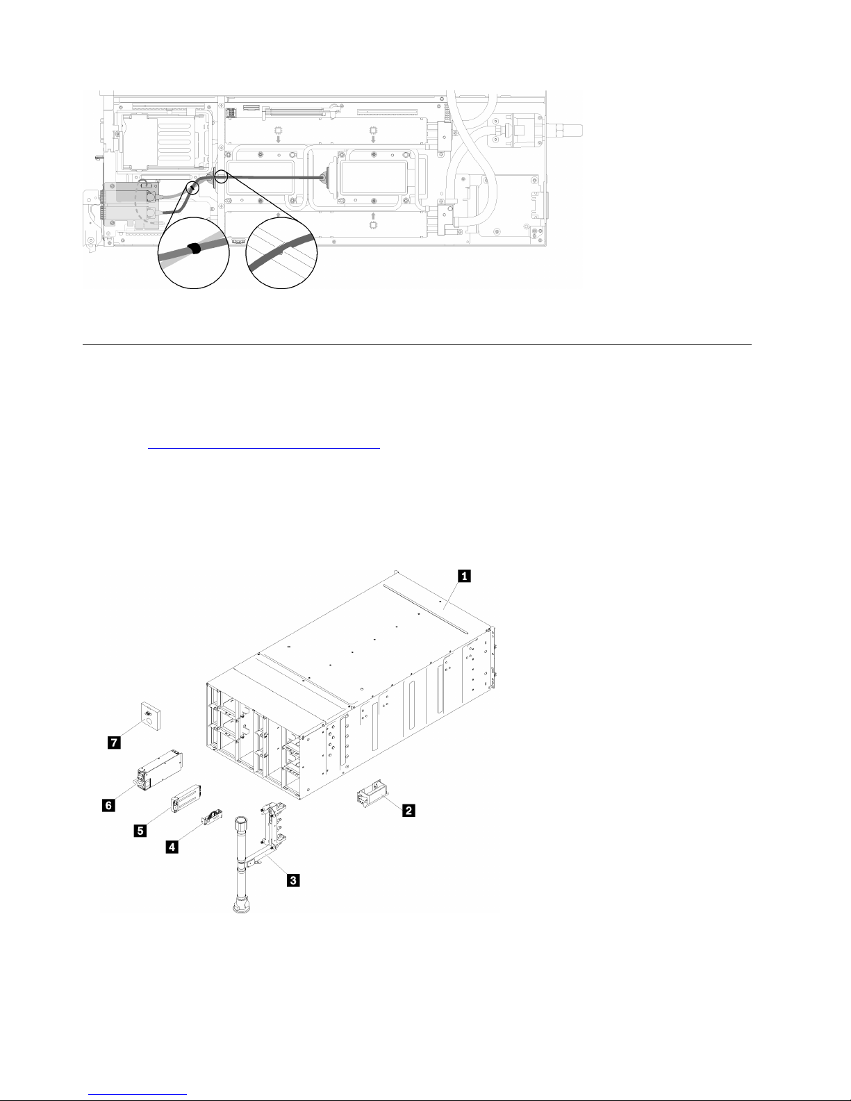
Figure 13. Cable routing - Internal Faceplate Transition (IFT) adapter
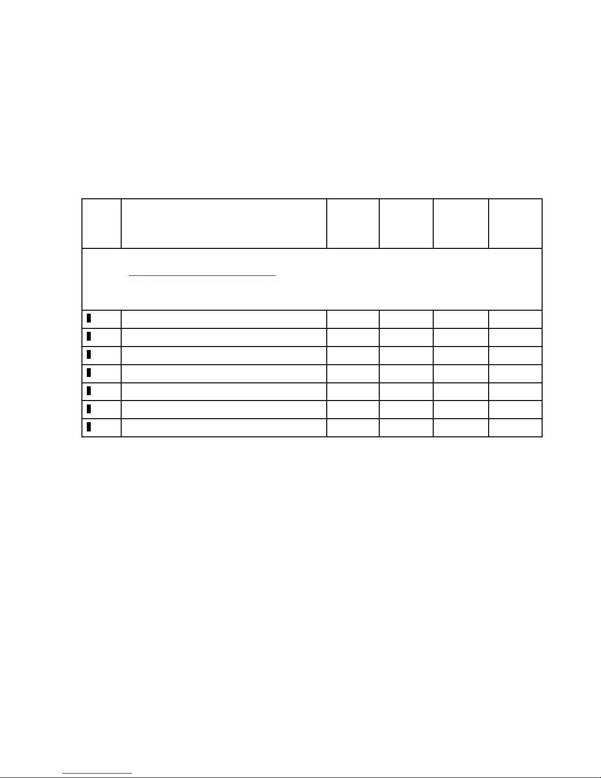
Parts list
Use the parts list to identify each of the components that are available for your solution.
For more information about ordering the parts shown in Figure 14 “Enclosure components” on page 22:
1. Go to
2. Click Service Parts.
3. Enter the serial number to view a listing of parts for your solution.
Note: Depending on the model, your solution might look slightly different from the illustration.
• Enclosure components
http://datacentersupport.lenovo.com and navigate to the support page for your solution.
Figure 14. Enclosure components
The parts listed in the following table are identified as one of the following:
22
ThinkSystem SD650 Dual Node DWC Tray and NeXtScale n1200 DWC Enclosure Setup Guide
– Tier 1 customer replaceable unit (CRU): Replacement of Tier 1 CRUs is your responsibility. If Lenovo
installs a Tier 1 CRU at your request with no service agreement, you will be charged for the installation.
– Tier 2 customer replaceable unit: You may install a Tier 2 CRU yourself or request Lenovo to install it,
at no additional charge, under the type of warranty service that is designated for your solution.
– Field replaceable unit (FRU): FRUs must be installed only by trained service technicians.
– Consumable and Structural parts: Purchase and replacement of consumable and structural parts
(components, such as a cover or bezel) is your responsibility. If Lenovo acquires or installs a structural
component at your request, you will be charged for the service.
Table 9. Parts listing
Index Description Tier 1
CRU
Tier 2
CRU
FRU Consuma-
ble and
Structural
part
For more information about ordering the parts shown in Figure 14 “Enclosure components” on page 22:
1. Go to
http://datacentersupport.lenovo.com and navigate to the support page for your solution.
2. Click Service Parts.
3. Enter the serial number to view a listing of parts for your solution.
1
2
3
4
5
6
7
6U enclosure assembly
Lift handle
Manifold assembly
Drip sensor assembly
Fan and Power Control module
Power supply
Fan module filler
√
√
√
√
√
√
√
Chapter 2. Solution components 23
 Loading...