

Page 1

ThinkServer RD120 Ty pes 6444, 6445, 6446, and 6447
Installation Guid e
Page 2

Page 3

ThinkServer RD120 Ty pes 6444, 6445, 6446, and 6447
Installation Guid e
Page 4

Note: Before using this information and the product it supports, read the general information in Appendix B, “Notices,” on page 85
and the Warranty and Support Information document on the Lenovo ThinkServer Documentation DVD.
First Edition (October 2008)
© Copyright Lenovo 2008.
Portions © Copyright International Business Machines Corporation 2007.
All rights reserved.
LENOVO products, data, computer software, and services have been developed exclusively at private expense and
are sold to governmental entities as commercial items as defined by 48 C.F.R. 2.101 with limited and restricted rights
to use, reproduction and disclosure.
LIMITED AND RESTRICTED RIGHTS NOTICE: If products, data, computer software, or services are delivered
pursuant a General Services Administration ″GSA″ contract, use, reproduction, or disclosure is subject to restrictions
set forth in Contract No. GS-35F-05925.
Page 5

Contents
Safety . . . . . . . . . . . . . . . . . . . . . . . . . . . .v
Chapter 1. Introduction . . . . . . . . . . . . . . . . . . . . . .1
The Lenovo ThinkServer Documentation DVD . . . . . . . . . . . . . .2
Hardware and software requirements . . . . . . . . . . . . . . . .2
Notices and statements in this document . . . . . . . . . . . . . . . .3
Features and specifications . . . . . . . . . . . . . . . . . . . . .3
Major components of the server . . . . . . . . . . . . . . . . . . .5
Chapter 2. Installing optional devices . . . . . . . . . . . . . . . .7
Installation guidelines . . . . . . . . . . . . . . . . . . . . . . .7
System reliability guidelines . . . . . . . . . . . . . . . . . . . .8
Working inside the server with the power on . . . . . . . . . . . . .8
Handling static-sensitive devices . . . . . . . . . . . . . . . . . .9
Removing the cover . . . . . . . . . . . . . . . . . . . . . . .9
Installing a memory module . . . . . . . . . . . . . . . . . . . .10
Memory mirroring . . . . . . . . . . . . . . . . . . . . . . .13
Online-spare memory . . . . . . . . . . . . . . . . . . . . .14
Installing a hard disk drive . . . . . . . . . . . . . . . . . . . . .16
Installing a tape drive . . . . . . . . . . . . . . . . . . . . . .17
Installing an additional microprocessor . . . . . . . . . . . . . . . .18
Installing an adapter . . . . . . . . . . . . . . . . . . . . . . .24
Installing a Remote Supervisor Adapter II SlimLine . . . . . . . . . . . .27
Replacing the ServeRAID SAS controller . . . . . . . . . . . . . . .29
Completing the installation . . . . . . . . . . . . . . . . . . . . .30
Installing the cover . . . . . . . . . . . . . . . . . . . . . .31
Connecting the cables . . . . . . . . . . . . . . . . . . . . .31
Updating the server configuration . . . . . . . . . . . . . . . . .32
Chapter 3. Server controls, LEDs, and power . . . . . . . . . . . . .35
Front view . . . . . . . . . . . . . . . . . . . . . . . . . .35
Rear view . . . . . . . . . . . . . . . . . . . . . . . . . . .37
Server power features . . . . . . . . . . . . . . . . . . . . . .38
Turning on the server . . . . . . . . . . . . . . . . . . . . .39
Turning off the server . . . . . . . . . . . . . . . . . . . . .39
Chapter 4. Configuring the server . . . . . . . . . . . . . . . . .41
Using the ThinkServer EasyStartup program . . . . . . . . . . . . . .41
Using ThinkServer EasyManage products . . . . . . . . . . . . . .43
Using the Configuration/Setup Utility program . . . . . . . . . . . . .43
Configuring the Gigabit Ethernet controllers . . . . . . . . . . . . . .43
Using the RAID configuration programs . . . . . . . . . . . . . . . .44
Using the IBM ServeRAID Configuration Utility program . . . . . . . . .44
Using ServeRAID Manager . . . . . . . . . . . . . . . . . . .45
Using the baseboard management controller . . . . . . . . . . . . . .47
Enabling and configuring SOL using the OSA SMBridge management utility
program . . . . . . . . . . . . . . . . . . . . . . . . .47
Installing the OSA SMBridge management utility program . . . . . . . .56
Using the baseboard management controller utility programs . . . . . . .58
Chapter 5. Solving problems . . . . . . . . . . . . . . . . . . .61
Diagnostic tools overview . . . . . . . . . . . . . . . . . . . . .61
POST beep codes . . . . . . . . . . . . . . . . . . . . . . .61
© Lenovo 2008. Portions © IBM Corp. 2007. iii
Page 6

POST error codes . . . . . . . . . . . . . . . . . . . . . . . .63
EasyStartup problems . . . . . . . . . . . . . . . . . . . . . .64
Troubleshooting tables . . . . . . . . . . . . . . . . . . . . . .65
CD-RW/DVD drive problems . . . . . . . . . . . . . . . . . . .65
General problems . . . . . . . . . . . . . . . . . . . . . . .66
Hard disk drive problems . . . . . . . . . . . . . . . . . . . .66
Intermittent problems . . . . . . . . . . . . . . . . . . . . . .67
USB keyboard, mouse, or pointing-device problems . . . . . . . . . .68
Memory problems . . . . . . . . . . . . . . . . . . . . . . .69
Microprocessor problems . . . . . . . . . . . . . . . . . . . .70
Monitor problems . . . . . . . . . . . . . . . . . . . . . . .71
Optional-device problems . . . . . . . . . . . . . . . . . . . .73
Power problems . . . . . . . . . . . . . . . . . . . . . . .73
Serial port problems . . . . . . . . . . . . . . . . . . . . . .75
Software problems . . . . . . . . . . . . . . . . . . . . . .76
Universal Serial Bus (USB) port problems . . . . . . . . . . . . . .77
Video problems . . . . . . . . . . . . . . . . . . . . . . . .77
Light path diagnostics . . . . . . . . . . . . . . . . . . . . . .77
Diagnosing problems using light path diagnostics . . . . . . . . . . .78
Light path diagnostics LEDs . . . . . . . . . . . . . . . . . . .78
Appendix A. Getting help and technical assistance . . . . . . . . . .81
Before you call . . . . . . . . . . . . . . . . . . . . . . . . .81
Using the documentation . . . . . . . . . . . . . . . . . . . . .81
Getting help and information from the World Wide Web . . . . . . . . . .82
Calling for service . . . . . . . . . . . . . . . . . . . . . . . .82
Using other services . . . . . . . . . . . . . . . . . . . . . . .83
Purchasing additional services . . . . . . . . . . . . . . . . . . .83
Lenovo product service . . . . . . . . . . . . . . . . . . . . . .83
Appendix B. Notices . . . . . . . . . . . . . . . . . . . . . .85
Trademarks . . . . . . . . . . . . . . . . . . . . . . . . . .86
Important notes . . . . . . . . . . . . . . . . . . . . . . . . .86
Waste electrical and electronic equipment (WEEE) notices . . . . . . . . .87
Battery return program . . . . . . . . . . . . . . . . . . . . . .88
German Ordinance for Work gloss statement . . . . . . . . . . . . . .89
Electronic emissions notices . . . . . . . . . . . . . . . . . . . .89
Federal Communications Commission (FCC) statement . . . . . . . . .89
Industry Canada Class A emission compliance statement . . . . . . . .90
Avis de conformité à la réglementation d'Industrie Canada . . . . . . . .90
Australia and New Zealand Class A statement . . . . . . . . . . . .90
United Kingdom telecommunications safety requirement . . . . . . . . .90
European Union EMC Directive conformance statement . . . . . . . . .90
German Class A compliance statement . . . . . . . . . . . . . . .90
Japanese Voluntary Control Council for Interference (VCCI) statement . . .91
Taiwanese Class A warning statement . . . . . . . . . . . . . . .92
Chinese Class A warning statement . . . . . . . . . . . . . . . .92
Korean Class A warning statement . . . . . . . . . . . . . . . .92
Index . . . . . . . . . . . . . . . . . . . . . . . . . . . .93
iv ThinkServer RD120 Types 6444, 6445, 6446, and 6447: Installation Guide
Page 7
Safety
Before installing this product, read the Safety Information.
Antes de instalar este produto, leia as Informações de Segurança.
Pred instalací tohoto produktu si prectete prírucku bezpecnostních instrukcí.
Læs sikkerhedsforskrifterne, før du installerer dette produkt.
Lees voordat u dit product installeert eerst de veiligheidsvoorschriften.
Ennen kuin asennat tämän tuotteen, lue turvaohjeet kohdasta Safety Information.
Avant d’installer ce produit, lisez les consignes de sécurité.
Vor der Installation dieses Produkts die Sicherheitshinweise lesen.
Prima di installare questo prodotto, leggere le Informazioni sulla Sicurezza.
Les sikkerhetsinformasjonen (Safety Information) før du installerer dette produktet.
Antes de instalar este produto, leia as Informações sobre Segurança.
Antes de instalar este producto, lea la información de seguridad.
Läs säkerhetsinformationen innan du installerar den här produkten.
© Lenovo 2008. Portions © IBM Corp. 2007. v
Page 8

Important:
Each caution and danger statement in this document is labeled with a number. This
number is used to cross reference an English-language caution or danger
statement with translated versions of the caution or danger statement in the Safety
Information document.
For example, if a caution statement is labeled “Statement 1”, translations for that
caution statement are in the Safety Information document under “Statement 1.”
Be sure to read all caution and danger statements in this document before you
perform the procedures. Read any additional safety information that comes with the
server or optional device before you install the device.
Attention: The information in this document regarding installing and removing
power supplies and connecting and disconnecting power refers to ac power
supplies only. If the server contains dc power supplies, see the documentation that
comes with the dc power supplies. In a dc power environment, only trained service
personnel other than Lenovo service technicians are authorized to connect or
disconnect power to the dc power supply and to install and remove a dc power
supply.
vi ThinkServer RD120 Types 6444, 6445, 6446, and 6447: Installation Guide
Page 9
Statement 1:
DANGER
Electrical
current from power, telephone, and communication cables is
hazardous.
To avoid a shock hazard:
v Do not connect or disconnect any cables or perform installation,
maintenance, or reconfiguration of this product during an electrical
storm.
v Connect all power cords to a properly wired and grounded electrical
outlet.
v Connect to properly wired outlets any equipment that will be attached to
this product.
v When possible, use one hand only to connect or disconnect signal
cables.
v Never turn on any equipment when there is evidence of fire, water, or
structural damage.
v Disconnect the attached power cords, telecommunications systems,
networks, and modems before you open the device covers, unless
instructed otherwise in the installation and configuration procedures.
v Connect and disconnect cables as described in the following table when
installing, moving, or opening covers on this product or attached
devices.
To Connect: To Disconnect:
1. Turn everything OFF.
2. First, attach all cables to devices.
3. Attach signal cables to connectors.
4. Attach power cords to outlet.
1. Turn everything OFF.
2. First, remove power cords from outlet.
3. Remove signal cables from connectors.
4. Remove all cables from devices.
5. Turn device ON.
Safety vii
Page 10

Statement 2:
CAUTION:
When replacing the lithium battery, use only the battery recommended by the
manufacturer. If your system has a module containing a lithium battery,
replace it only with the same module type made by the same manufacturer.
The battery contains lithium and can explode if not properly used, handled, or
disposed of.
Do not
v Throw or immerse into water
v Heat to more than 100°C (212°F)
v Repair or disassemble
Dispose
of the battery as required by local ordinances or regulations.
viii ThinkServer RD120 Types 6444, 6445, 6446, and 6447: Installation Guide
Page 11
Statement 3:
CAUTION:
When laser products (such as CD drives, DVD drives, fiber optic devices, or
transmitters) are installed, note the following:
v Do not remove the covers. Removing the covers of the laser product could
result in exposure to hazardous laser radiation. There are no serviceable
parts inside the device.
v Use of controls or adjustments or performance of procedures other than
those specified herein might result in hazardous radiation exposure.
DANGER
laser products contain an embedded Class 3A or Class 3B laser
Some
diode. Note the following.
Laser radiation when open. Do not stare into the beam, do not view directly
with optical instruments, and avoid direct exposure to the beam.
Class 1 Laser Product
Laser Klasse 1
Laser Klass 1
Luokan 1 Laserlaite
Appareil A Laser de Classe 1
`
Safety ix
Page 12
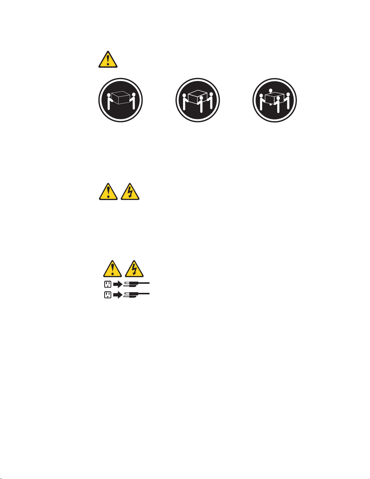
Statement 4:
≥ 18 kg (39.7 lb) ≥ 32 kg (70.5 lb) ≥ 55 kg (121.2 lb)
CAUTION:
Use safe practices when lifting.
Statement 5:
CAUTION:
The power control button on the device and the power switch on the power
supply do not turn off the electrical current supplied to the device. The device
also might have more than one power cord. To remove all electrical current
from the device, ensure that all power cords are disconnected from the power
source.
2
1
x ThinkServer RD120 Types 6444, 6445, 6446, and 6447: Installation Guide
Page 13
Statement 8:
CAUTION:
Never remove the cover on a power supply or any part that has the following
label attached.
Hazardous voltage, current, and energy levels are present inside any
component that has this label attached. There are no serviceable parts inside
these components. If you suspect a problem with one of these parts, contact
a service technician.
Statement 26:
CAUTION:
Do not place any object on top of rack-mounted devices.
Safety xi
Page 14

This server is suitable for use on an IT power-distribution system whose maximum
phase-to-phase voltage is 240 V under any distribution fault condition.
Important: This product is not suitable for use with visual display workplace
devices according to Clause 2 of the German Ordinance for Work with Visual
Display Units.
xii ThinkServer RD120 Types 6444, 6445, 6446, and 6447: Installation Guide
Page 15

Chapter 1. Introduction
This Installation Guide contains instructions for setting up your Lenovo
®
ThinkServer™ RD120 Types 6444, 6445, 6446, and 6447 server and basic
instructions for installing some optional devices. More detailed instructions for
installing optional devices are in the User Guide on the ThinkServer Documentation
DVD, which comes with the server. This document contains information about:
v Setting up and cabling the server
v Starting and configuring the server
v Installing some optional devices
v Solving problems
Attention: The information in this document regarding installing and removing
power supplies and connecting and disconnecting power refers to ac power
supplies only. If the server contains dc power supplies, see the documentation that
comes with the dc power supplies. In a dc power environment, only trained service
personnel other than Lenovo service technicians are authorized to connect or
disconnect power to the dc power supply and to install and remove a dc power
supply.
The server has two model styles, which are based on the size and number of hard
disk drive bays:
v The 3.5-inch models have six 3.5-inch hot-swap hard disk drive bays. Install only
3.5-inch drives in these models. If you intend to install a tape drive, the tape
drive will occupy two of the six 3.5-inch drive bays.
v The 2.5-inch models have eight 2.5-inch hot-swap hard disk drive bays and one
3.5-inch tape drive bay. Install only 2.5-inch hard disk drives and an optional
3.5-inch tape drive in these models.
Throughout this documentation, the terms 2.5-inch models and 3.5-inch models are
used to distinguish between the server styles.
If firmware and documentation updates are available, you can download them from
the Lenovo Web site. The server might have features that are not described in the
documentation that comes with the server, and the documentation might be updated
occasionally to include information about those features, or technical updates might
be available to provide additional information that is not included in the server
documentation. To check for updates, complete the following steps:
Changes are made periodically to the Lenovo Web site. The actual
Note:
procedure might vary slightly from what is described in this document.
1. Go to: http://www.lenovo.com/support.
© Lenovo 2008. Portions © IBM Corp. 2007. 1
Page 16

2. Enter your product number (machine type and model number) or select Servers
from the Select your product list.
3. Select Servers from the Brand list.
4. From Family list, select ThinkServer RD120, and click Continue.
server comes with an ThinkServer EasyStartup DVD to help you configure the
The
hardware, install device drivers, and install the operating system.
The server comes with a limited warranty. You can obtain up-to-date information
about the server and other Lenovo products at http://www.lenovo.com/thinkserver.
Record information about the server in the following table. You will need this
information when you register the server with Lenovo.
Product name ThinkServer RD120
Machine type 6444, 6445, 6446, and 6447
Model number _____________________________________________
Serial number _____________________________________________
The model number and serial number are on the ID label 1 on the bezel, as
shown in the following illustration.
Note: This illustration shows a model with 3.5-inch serial-attached SCSI (SAS)
hot-swap hard disk drives. Models with 2.5-inch SAS hot-swap hard disk drives are
also available. The location of the ID label is the same on both model styles. This
illustration might differ slightly from your hardware.
For a list of supported optional devices for the server, see http://www.lenovo.com/
accessories.
See the Rack Installation Instructions document for complete rack installation and
removal instructions.
The Lenovo ThinkServer Documentation DVD
The Lenovo ThinkServer Documentation DVD contains documentation for the
server in Portable Document Format (PDF).
Hardware and software requirements
The Lenovo ThinkServer Documentation DVD requires the following minimum
hardware and software:
2 ThinkServer RD120 Types 6444, 6445, 6446, and 6447: Installation Guide
Page 17

v Microsoft® Windows® XP, Windows 2000, or Red Hat Linux
v 100 MHz microprocessor
v 32 MB of RAM
v Adobe® Acrobat® Reader 3.0 (or later) or xpdf, which comes with Linux operating
systems
Notices and statements in this document
The caution and danger statements that appear in this document are also in the
multilingual Safety Information document, which is on the Lenovo ThinkServer
Documentation DVD. Each statement is numbered for reference to the
corresponding statement in the Safety Information document.
The following notices and statements are used in this document:
v Note: These notices provide important tips, guidance, or advice.
v Important: These notices provide information or advice that might help you avoid
inconvenient or problem situations.
v Attention: These notices indicate potential damage to programs, devices, or
data. An attention notice is placed just before the instruction or situation in which
damage could occur.
v Caution: These statements indicate situations that can be potentially hazardous
to you. A caution statement is placed just before the description of a potentially
hazardous procedure step or situation.
v Danger: These statements indicate situations that can be potentially lethal or
extremely hazardous to you. A danger statement is placed just before the
description of a potentially lethal or extremely hazardous procedure step or
situation.
Features and specifications
The following information is a summary of the features and specifications of the
server. Depending on the server model, some features might not be available, or
some specifications might not apply.
Racks are marked in vertical increments of 4.45 cm (1.75 inches). Each increment
is referred to as a unit, or “U.” A 1-U-high device is 1.75 inches tall.
Notes:
1. Power consumption and heat output vary depending on the number and type of
optional features that are installed and the power-management optional features
that are in use.
2. The sound levels were measured in controlled acoustical environments
according to the procedures specified by the American National Standards
Institute (ANSI) S12.10 and ISO 7779 and are reported in accordance with ISO
9296. Actual sound-pressure levels in a given location might exceed the
average values stated because of room reflections and other nearby noise
sources. The declared sound-power levels indicate an upper limit, below which
a large number of computers will operate.
Chapter 1. Introduction 3
Page 18

Table 1. Features and specifications
Microprocessor:
v Intel® Xeon™ FC-LGA 771 dual-core
with 4 MB Level-2 cache or
quad-core with 8 MB (2x4 MB)
Level-2 cache
v Support for up to two
microprocessors
v Support for Intel Extended Memory
64 Technology (EM64T)
Note:
v Use the Configuration/Setup Utility
program to determine the type and
speed of the microprocessors.
Memory:
v Twelve DIMM connectors
v Minimum: 1 GB
v Maximum: 48 GB
v Type: Fully buffered DIMM (FBD)
PC2-5300 DIMMs only
v Sizes: 512 MB, 1 GB, 2 GB, or
4 GB (when available), in pairs
v Chipkill™ supported
Drives:
CD/DVD: IDE 24x CD-RW/ 8x DVD
combination
Expansion bays:
v Hot-swap hard disk drive bays:
SAS only. Number and size depend
on the server model. One of the
following configurations:
– Six 3.5-inch drive bays (optional
tape drive [SATA or SCSI]
requires two of these bays)
– Eight 2.5-inch drive bays and
one tape-drive (SATA or SCSI)
bay
v
One 5.25-inch Ultrabay Enhanced
bay (CD-RW/DVD drive installed)
Expansion
slots:
v Two PCI Express x8 slots (x4
lanes) on system board (low profile)
v Support for either of the following
optional riser cards:
– Riser card with two PCI Express
x8 slots (x8 lanes) (standard)
– Riser card with two 133
MHz/64-bit PCI-X slots
Hot-swap fans:
v Standard: Five
v Maximum: Ten - provide
redundant cooling
Hot-swap
power supplies:
835 watts (100 - 240 V ac)
v Minimum: One
v Maximum: Two - provide
redundant power
(2 U):
Size
v Height: 85.4 mm (3.36 in.)
v Depth: 705 mm (27.8 in.)
v Width: 443.6 mm (17.5 in.)
v Weight: approximately 21.09 kg
(46.5 lb) to 29.03 kg (64 lb)
depending upon configuration
Integrated
functions:
v Baseboard management controller
v Two Broadcom 10/100/1000
Ethernet controllers with Wake on
LAN® support and TCP/IP Offload
Engine (TOE) support
v One RAID controller, active only
when a 8k or 8k-l SAS controller
is installed
v One serial port
v One serial-attached SCSI (SAS)
controller
v Seven Universal Serial Bus (USB)
ports (two on front and four on
rear of server, plus one internal),
v2.0 supporting v1.1
v Two video ports (one on front and
one on rear of server)
v One internal serial ATA (SATA)
connector for tape
v Support for Remote Supervisor
Adapter II SlimLine
Note:
In messages and
documentation, the term service
processor refers to the baseboard
management controller or the
optional Remote Supervisor Adapter
II SlimLine.
Video controller:
v ATI RN50 video on system board
v Compatible with SVGA and VGA
v 16 MB DDR video memory
ServeRAID SAS controller:
v ServeRAID™-8k-l SAS Controller that
supports RAID levels 0, 1, 10
(standard)
v Upgradeable to ServeRAID-8k SAS
Controller, 256 MB with battery
backup, that supports RAID levels 0,
1, 1E, 5, 6, and 10
Environment:
v Air temperature:
– Server on: 10° to 35°C (50.0° to
95.0°F); altitude: 0 to 914.4 m
(3000 ft). Decrease system
temperature by 0.75°C for every
1000-foot increase in altitude.
– Server off: 10° to 43°C (50.0° to
109.4°F); maximum altitude: 2133
m (7000 ft)
– Shipment: -40° to +60°C (-40° to
140°F); maximum altitude: 2133
m (7000 ft)
v
Humidity:
– Server on/off: 8% to 80%
– Shipment: 5% to 100%
Acoustical
noise emissions:
v Declared sound power, idle: 6.8 bel
v Declared sound power, operating:
6.8 bel
Heat
output:
Approximate heat output in British
thermal units (Btu) per hour:
v Minimum configuration: 1230 Btu per
hour (360 watts)
v Maximum configuration: 3390 Btu
per hour (835 watts)
Electrical
input with hot-swap ac
power supplies:
v Sine-wave input (50-60 Hz) required
v Input voltage range automatically
selected
v Input voltage low range:
– Minimum: 100 V ac
– Maximum: 127 V ac
v
Input voltage high range:
– Minimum: 200 V ac
– Maximum: 240 V ac
v
Input kilovolt-amperes (kVA)
approximately:
– Minimum: 0.29 kVA
– Maximum: 1.00 kVA
4 ThinkServer RD120 Types 6444, 6445, 6446, and 6447: Installation Guide
Page 19
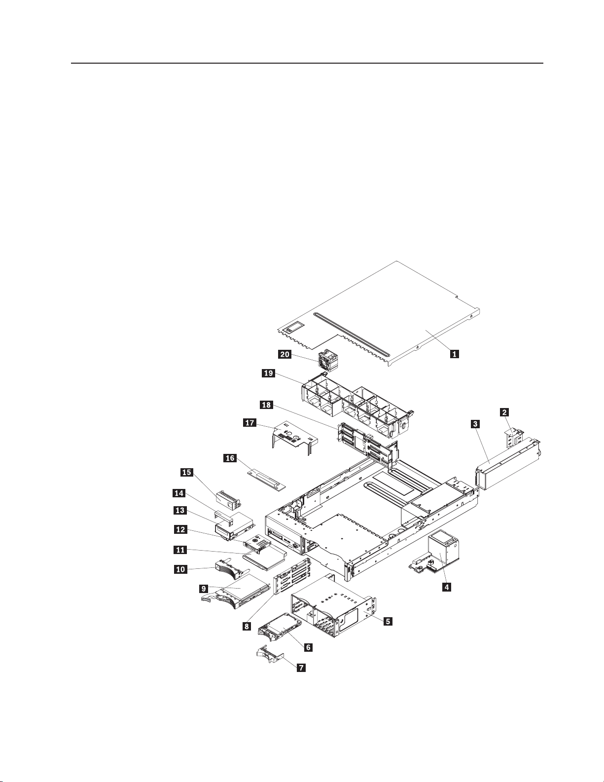
Major components of the server
Blue on a component indicates touch points, where you can grip the component to
remove it from or install it in the server, open or close a latch, and so on.
Orange on a component or an orange label on or near a component indicates that
the component can be hot-swapped, which means that if the server and operating
system support hot-swap capability, you can remove or install the component while
the server is running. (Orange can also indicate touch points on hot-swap
components.) See the instructions for removing or installing a specific hot-swap
component for any additional procedures that you might have to perform before you
remove or install the component.
The following illustrations show the major components in the server.
Note: The illustrations in this document might differ slightly from your hardware.
1 Cover 11 CD/DVD drive
2 Power-supply filler 12 Operator information panel
3 Power supply 13 Optional tape drive
Chapter 1. Introduction 5
Page 20

4 Power backplane 14 Tape drive space filler
5 2.5-inch drive cage with hard disk
15 Tape drive filler
drive backplane
6 2.5-inch hard disk drive 16 CD/DVD media backplane
7 2.5-inch filler panel 17 Microprocessor air baffle
8 3.5-inch cage divider 18 3.5-inch hard disk drive backplane
9 3.5-inch hard disk drive 19 Fan bracket assembly
10 3.5-inch filler panel 20 Fans (5 or 10)
1 Riser-card assembly 8 VRM
2 Full-height adapter 9 Microprocessor
3 DIMM air baffle 10 Heat sink
4 DIMM 11 Heat sink filler
5 ServerRAID SAS controller 12 Remote Supervisor Adapter II
6 system board 13 Low-profile adapter
7 Heat sink retention module
6 ThinkServer RD120 Types 6444, 6445, 6446, and 6447: Installation Guide
SilmLine
Page 21

Chapter 2. Installing optional devices
This chapter provides basic instructions for installing optional hardware devices in
the server. These instructions are intended for users who are experienced with
setting up Lenovo® server hardware. If you need more detailed instructions, see the
User Guide on the ThinkServer Documentation DVD.
Installation guidelines
Before you install optional devices, read the following information:
v Read the safety information that begins on page v and the guidelines in
“Handling static-sensitive devices” on page 9. This information will help you work
safely.
v When you install your new server, take the opportunity to download and apply
the most recent firmware updates. This step will help to ensure that any known
issues are addressed and that your server is ready to function at maximum levels
of performance. To download firmware updates for your server, complete the
following steps:
Changes are made periodically to the Lenovo Web site. The actual
Note:
procedure might vary slightly from what is described in this document.
1. Go to: http://www.lenovo.com/support.
2. Enter your product number (machine type and model number) or select
Servers from the Select your product list.
3. Select Servers from the Brand list.
4. From Family list, select ThinkServer RD120, and click Continue.
5. Click Downloads and drivers to download firmware updates.
Before you install optional hardware, make sure that the server is working
v
correctly. Start the server, and make sure that the operating system starts, if an
operating system is installed, or that a 19990305 error code is displayed,
indicating that an operating system was not found but the server is otherwise
working correctly. If the server is not working correctly, see Chapter 5, “Solving
problems,” on page 61 for diagnostic information.
v Observe good housekeeping in the area where you are working. Place removed
covers and other parts in a safe place.
v If you must start the server while the cover is removed, make sure that no one is
near the server and that no tools or other objects have been left inside the
server.
v Do not attempt to lift an object that you think is too heavy for you. If you have to
lift a heavy object, observe the following precautions:
– Make sure that you can stand safely without slipping.
– Distribute the weight of the object equally between your feet.
– Use a slow lifting force. Never move suddenly or twist when you lift a heavy
object.
– To avoid straining the muscles in your back, lift by standing or by pushing up
with your leg muscles.
Make sure that you have an adequate number of properly grounded electrical
v
outlets for the server, monitor, and other devices.
v Back up all important data before you make changes to disk drives.
v Have a small flat-blade screwdriver available.
© Lenovo 2008. Portions © IBM Corp. 2007. 7
Page 22

v You do not have to turn off the server to install or replace hot-swap fans,
redundant hot-swap ac power supplies, or hot-plug Universal Serial Bus (USB)
devices. However, you must turn off the server before performing any steps that
involve removing or installing adapter cables or non-hot-swap optional devices or
components.
Attention: In a dc power environment, only trained service personnel other
than Lenovo service technicians are authorized to connect or disconnect power
to the dc power supply and to install and remove a dc power supply. See the
documentation that comes with each dc power supply.
v Blue on a component indicates touch points, where you can grip the component
to remove it from or install it in the server, open or close a latch, and so on.
v Orange on a component or an orange label on or near a component indicates
that the component can be hot-swapped, which means that if the server and
operating system support hot-swap capability, you can remove or install the
component while the server is running. (Orange can also indicate touch points on
hot-swap components.) See the instructions for removing or installing a specific
hot-swap component for any additional procedures that you might have to
perform before you remove or install the component.
v When you are finished working on the server, reinstall all safety shields, guards,
labels, and ground wires.
v For a list of supported optional devices for the server, see http://www.lenovo.com/
accessories.
System reliability guidelines
To help ensure proper cooling and system reliability, make sure that the following
requirements are met:
v Each of the drive bays has a drive or a filler panel and electromagnetic
compatibility (EMC) shield installed in it.
v If the server has redundant power, each of the power-supply bays has a power
supply installed in it.
v There is adequate space around the server to allow the server cooling system to
work properly. Leave approximately 50 mm (2.0 in.) of open space around the
front and rear of the server. Do not place objects in front of the fans. For proper
cooling and airflow, replace the server cover before turning on the server.
Operating the server for extended periods of time (more than 30 minutes) with
the server cover removed might damage server components.
v You have followed the cabling instructions that come with optional adapters.
v You have replaced a failed fan within 48 hours.
v You have replaced a hot-swap drive within 2 minutes of removal.
v You do not operate the server without the air baffles installed. Operating the
server without the air baffles might cause the microprocessors to overheat.
v Microprocessor socket 2 always contains either a heat-sink filler or a
microprocessor and heat sink.
Working inside the server with the power on
Attention: Static electricity that is released to internal server components when
the server is powered-on might cause the server to halt, which could result in the
loss of data. To avoid this potential problem, always use an electrostatic-discharge
wrist strap or other grounding system when working inside the server with the
power on.
8 ThinkServer RD120 Types 6444, 6445, 6446, and 6447: Installation Guide
Page 23

The server supports hot-plug, hot-add, and hot-swap devices and is designed to
operate safely while it is turned on and the cover is removed. Follow these
guidelines when you work inside a server that is turned on:
v Avoid wearing loose-fitting clothing on your forearms. Button long-sleeved shirts
before working inside the server; do not wear cuff links while you are working
inside the server.
v Do not allow your necktie or scarf to hang inside the server.
v Remove jewelry, such as bracelets, necklaces, rings, and loose-fitting wrist
watches.
v Remove items from your shirt pocket, such as pens and pencils, that could fall
into the server as you lean over it.
v Avoid dropping any metallic objects, such as paper clips, hairpins, and screws,
into the server.
Handling static-sensitive devices
Attention: Static electricity can damage the server and other electronic devices.
To avoid damage, keep static-sensitive devices in their static-protective packages
until you are ready to install them.
To reduce the possibility of damage from electrostatic discharge, observe the
following precautions:
v Limit your movement. Movement can cause static electricity to build up around
you.
v The use of a grounding system is recommended. For example, wear an
electrostatic-discharge wrist strap, if one is available. Always use an
electrostatic-discharge wrist strap or other grounding system when working inside
the server with the power on
v Handle the device carefully, holding it by its edges or its frame.
v Do not touch solder joints, pins, or exposed circuitry.
v Do not leave the device where others can handle and damage it.
v While the device is still in its static-protective package, touch it to an unpainted
metal surface on the outside of the server for at least 2 seconds. This drains
static electricity from the package and from your body.
v Remove the device from its package and install it directly into the server without
setting down the device. If it is necessary to set down the device, put it back into
its static-protective package. Do not place the device on the server cover or on a
metal surface.
v Take additional care when handling devices during cold weather. Heating reduces
indoor humidity and increases static electricity.
Removing the cover
Important: Before you install optional hardware, make sure that the server is
working correctly. Start the server, and make sure that the operating system starts,
if an operating system is installed, or that a 19990305 error code is displayed,
indicating that an operating system was not found but the server is otherwise
working correctly. If the server is not working correctly, see the Hardware
Maintenance Manual for diagnostic information.
To remove the cover, complete the following steps:
1. Read the safety information that begins on page v and “Installation guidelines”
on page 7.
Chapter 2. Installing optional devices 9
Page 24

2. If you are planning to install or remove a microprocessor, memory module, PCI
adapter, battery, or other non-hot-swap optional device, turn off the server and
all attached devices and disconnect all external cables and power cords (see
“Turning off the server” on page 39).
Attention: In a dc power environment, only trained service personnel other
than Lenovo service technicians are authorized to connect or disconnect power
to the dc power supply. See the documentation that comes with each dc power
supply.
3. Press down on the left and right side latches and pull the server out of the rack
enclosure until both slide rails lock.
Note: You can reach the cables on the back of the server when the server is in
the locked position.
4. Lift the cover-release latch 1. Lift the cover off the server and set the cover
aside.
Attention: For proper cooling and airflow, replace the cover before you turn on
the server. Operating the server for extended periods of time (more than 30
minutes) with the cover removed might damage server components.
Installing a memory module
The following notes describe the types of dual inline memory modules (DIMMs) that
the server supports and other information that you must consider when installing
DIMMs:
v The server supports up to 12 Fully Buffered DIMM PC2-5300 512 MB, 1 GB, 2
GB, and 4 GB DIMMs, for a maximum of 48 GB of system memory. See
http://www.lenovo.com/accessories for a list of memory modules that you can use
with the server.
Note: Because some memory is reserved for system operation, the actual
usable memory size that is reported by the operating system is less than the total
installed size.
v The server comes with a minimum of two 512 MB DIMMs, installed in slots 1 and
4. When you install additional DIMMs, you must install two identical DIMMS at a
time, in the order shown in the following table, to maintain performance.
10 ThinkServer RD120 Types 6444, 6445, 6446, and 6447: Installation Guide
Page 25
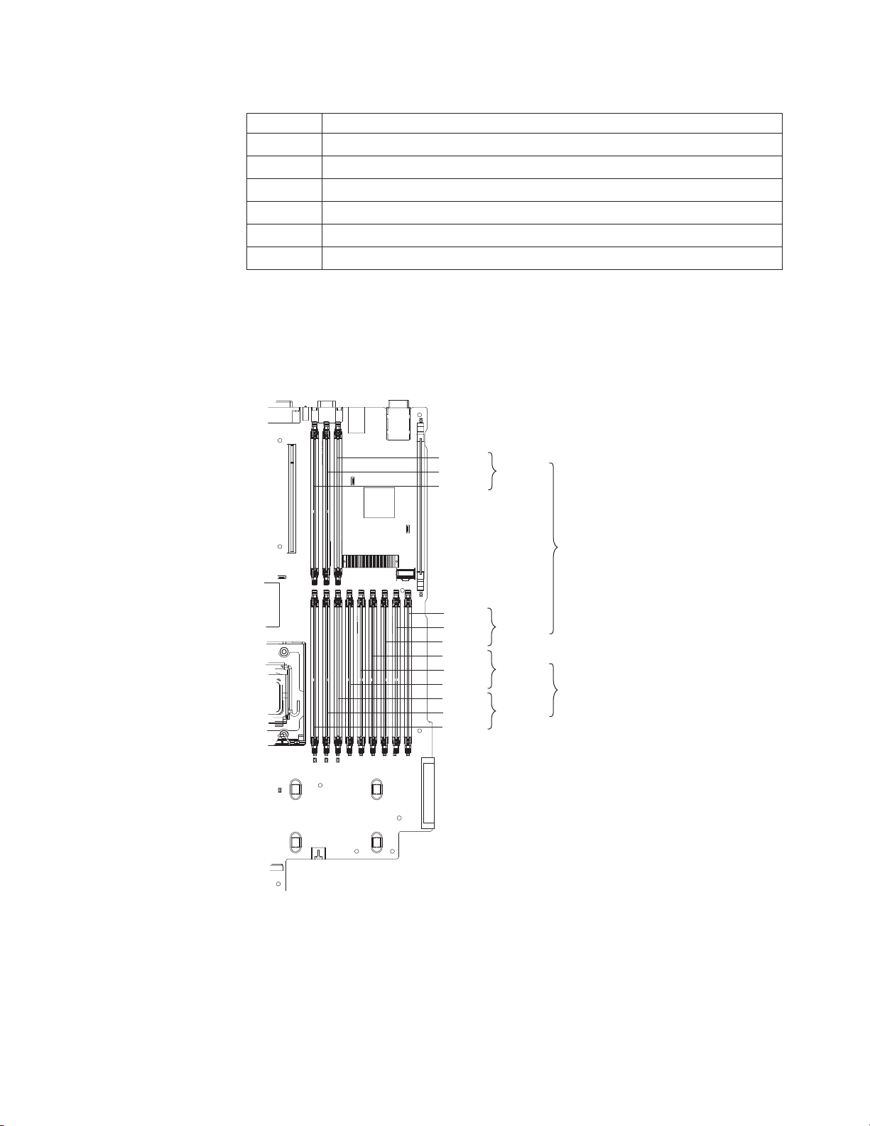
Table 2. DIMM installation sequence
Pair DIMM connectors
1 1 and 4
2 7 and 10
3 2 and 5
4 8 and 11
5 3 and 6
6 9 and 12
Note: When only one pair of DIMMs is installed in the server and the BIOS code
level is version 1.04 (GGE127A) or later, you can improve performance by
installing the DIMMs in connectors 1 and 7 instead of 1 and 4. However, because
the connectors in the pair are not on the same memory branch (see the following
illustration), Chipkill memory protection is disabled.
DIMM 12
DIMM 11
DIMM 10
DIMM 9
DIMM 8
DIMM 7
DIMM 6
DIMM 5
DIMM 4
DIMM 3
DIMM 2
DIMM 1
Channel 3
Branch 1
Channel 2
Channel 1
Branch 0
Channel 0
v Each DIMM in a pair must be the same size, speed, type, and technology to
ensure that the server will operate correctly.
v You can configure the server to use memory mirroring. Memory mirroring stores
data in two pairs of DIMMs simultaneously. If a failure occurs, the memory
controller switches from the active pair to the mirroring pair. See “Memory
mirroring” on page 13 for more information about memory mirroring and the
DIMM installation sequence that is required.
Chapter 2. Installing optional devices 11
Page 26

v The server supports online-spare memory. This feature disables the failed
memory from the system configuration and activates an online-spare pair of
DIMMs to replace the failed active DIMM pair. See “Online-spare memory” on
page 14 for more information about online-spare memory and the DIMM
configuration that is required.
v You can enable either online-spare memory or memory mirroring, but not both at
the same time. Online-spare memory provides more memory capacity than
mirroring; mirroring provides better memory protection but less memory capacity
than online-spare memory.
v When you install or remove DIMMs, the server configuration information
changes. When you restart the server, the system displays a message that
indicates that the memory configuration has changed.
To install a DIMM, complete the following steps:
1. Read the safety information that begins on page v and “Installation guidelines”
on page 7.
2. Turn off the server and peripheral devices, and disconnect the power cord and
all external cables.
Attention: In a dc power environment, only trained service personnel other
than Lenovo service technicians are authorized to connect or disconnect power
to the dc power supply. See the documentation that comes with each dc power
supply.
3. Remove the cover.
Attention: To avoid breaking the retaining clips or damaging the DIMM
connectors, open, and close the clips gently.
12 ThinkServer RD120 Types 6444, 6445, 6446, and 6447: Installation Guide
Page 27
1 DIMM air baffle 3 Finger hole
2 Riser card assembly 4 Release ring
4. Remove the riser-card assembly.
5. Remove the DIMM air baffle.
6. Open the retaining clip on each end of the DIMM connector.
7. Touch the static-protective package that contains the DIMM to any unpainted
metal surface on the outside of the server. Then, remove the DIMM from the
package.
8. Turn the DIMM so that the keys align correctly with the connector.
9. Insert the DIMM into the connector. Firmly press the DIMM straight down into
the connector. The retaining clips snap into the locked position when the DIMM
is firmly seated in the connector.
Note: If there is a gap between the DIMM and the retaining clips, the DIMM
has not been correctly inserted; open the retaining clips, remove the DIMM,
and then reinsert it.
10. Replace the DIMM air baffle.
11. Replace the riser-card assembly.
If you have other optional devices to install, do so now. Otherwise, go to
“Completing the installation” on page 30.
Memory mirroring
You can configure the server to use memory mirroring. Memory mirroring stores
data in two pairs of DIMMs simultaneously. If a failure occurs, the memory controller
Chapter 2. Installing optional devices 13
Page 28

switches from the active pair to the mirroring pair. Memory mirroring reduces the
amount of available memory. Enable memory mirroring through the
Configuration/Setup Utility program. See the section about using the
Configuration/Setup Utility program in the User Guide on the ThinkServer
Documentation DVD for details about enabling memory mirroring.
When you use memory mirroring, you must install two pairs of DIMMs at a time.
The four DIMMs in each group must be identical. See Table 3 for the DIMM
connectors that are in each group.
Table 3. Memory mirroring DIMM installation sequence
Group DIMM connectors
1 1, 4, 7, and 10
2 2, 5, 8, and 11
3 3, 6, 9, and 12
Table 4. Memory mirroring DIMM functions
Group Active DIMMs Mirroring DIMMs
1 1, 4 7, 10
2 2, 5 8, 11
3 3, 6 9, 12
Online-spare memory
The server supports online-spare memory. This feature disables the failed memory
from the system configuration and activates an online-spare pair of DIMMs to
replace the failed active DIMM pair.
Online-spare memory reduces the amount of available memory. Before you can
enable this feature, you must install up to two additional pairs of DIMMs. The
online-spare DIMM pairs must be the same speed, type, and the same size as, or
larger than, the largest active DIMM pairs.
Enable online-spare memory through the Configuration/Setup Utility program. The
BIOS code assigns the online-spare DIMM pairs according to your DIMM
configuration. Online-sparing is enabled on a memory branch basis; the BIOS code
does not enable online-sparing on a branch that cannot support online-sparing. See
the illustration on page 11 for the memory branch structure. DIMM ranks are
online-spared if the DIMMs are installed according to the rules in Table 5 on page
15 or Table 6 on page 15.
POST gives a warning message when online-sparing cannot be enabled on
Note:
both branches. However, no warning message is given when online-sparing is
enabled on one branch and disabled on the other.
Online-spare configurations are supported for each branch. See Table 5 on page 15
and Table 6 on page 15 for the online-spare DIMM connector assignments.
Important: Table 5 on page 15 shows the default DIMM online-spare scheme. If the
BIOS code level is version 1.04 or later, you can install the DIMMs according to the
scheme shown in Table 6 on page 15 instead.
14 ThinkServer RD120 Types 6444, 6445, 6446, and 6447: Installation Guide
Page 29

In the configuration that you use, install the largest DIMMs first.
Table 5. Online-spare DIMM configurations, basic scheme
Number of
DIMMs DIMM connectors Results
4 1 and 4 (largest DIMMs)
Online-sparing on branch 0
2 and 5
6 1 and 4 (largest DIMMs)
Online-sparing on branch 0
2 and 5
3 and 6
8 1 and 4 (largest DIMMs)
2 and 5
3 and 6
Online-sparing on branch 0
Online-sparing on dual-rank DIMMs on
branch 1
7 and 10 (dual-rank DIMMs only)
10 1 and 4 (largest DIMMs)
2 and 5
Online-sparing on branch 0
Online-sparing on branch 1
3 and 6
7 and 10
8 and 11
12 1 and 4 (largest DIMMs)
2 and 5
Online-sparing on branch 0
Online-sparing on branch 1
3 and 6
7 and 10
8 and 11
9 and 12
Table 6. Online-spare DIMM configurations, alternative scheme (requires BIOS code version
1.04 or later)
Number
of DIMMs DIMM connectors Results
4 7 and 10 (largest DIMMs)
8
and 11
6 7 and 10 (largest DIMMs)
Online-sparing on branch 1
Online-sparing on branch 1
8 and 11
9 and 12
8 7 and 10 (largest DIMMs)
8 and 11
9 and 12
Online-sparing on branch 1
Online-sparing on dual-rank DIMMs on
branch 0
1 and 4 (dual-rank DIMMs only)
10 1 and 4 (largest DIMMs)
2 and 5
Online-sparing on branch 0
Online-sparing on branch 1
7 and 10
8 and 11
9
and 12
12 N/A N/A
Chapter 2. Installing optional devices 15
Page 30
Installing a hard disk drive
Locate the documentation that comes with the hard disk drive and follow those
instructions in addition to the instructions in this chapter.
Important: Do not install a SCSI hard disk drive in this server; install only SAS hard
disk drives.
The following notes describe the type of hard disk drive that the server supports
and other information that you must consider when installing a hard disk drive:
v The server 3.5-inch models support six slim 3.5-inch hard disk drives installed on
Ultra-Slim hard disk drive trays for 3.5-inch drives.
v The server 2.5-inch models support eight 2.5-inch hot-swap hard disk drives
installed on Ultra-Slim hard disk drive trays for 2.5-inch drives.
v All hot-swap drives in the server should have the same throughput speed rating.
Mixing hard disk drives with different speed ratings will cause all drives to
operate at the lower throughput speed.
v The ID that is assigned to each bay is printed on the front of the server.
The following illustrations show how to install a hot-swap hard disk drive.
3.5-inch drives
1 Filler panel 3 Hard disk drive
2 Tray handle
16 ThinkServer RD120 Types 6444, 6445, 6446, and 6447: Installation Guide
Page 31

2.5-inch drives
To install a drive in a hot-swap bay, complete the following steps:
Attention: To maintain proper system cooling, do not operate the server for more
than 10 minutes without either a drive or a filler panel installed in each bay.
1. Read the safety information that begins on page v, and “Installation guidelines”
on page 7.
2. Remove the filler panel from one of the empty hot-swap bays.
3. Install the hard disk drive in the hot-swap bay:
a. Make sure that the tray handle is open (that is, perpendicular to the drive).
b. Align the drive assembly with the guide rails in the bay.
c. Gently push the drive assembly into the bay until the drive stops.
d. Push the tray handle to the closed (locked) position.
e. Check the hard disk drive status LED to verify that the hard disk drive is
operating correctly.
If the amber hard disk drive status LED for a drive is lit continuously, that
drive is faulty and must be replaced. If the green hard disk drive activity LED
is flashing, the drive is being accessed.
You might have to reconfigure the disk arrays after you install hard disk
Note:
drives. See the RAID documentation on the ThinkServer Documentation DVD
for information about RAID controllers.
you have other optional devices to install or remove, do so now. Otherwise, go to
If
“Completing the installation” on page 30.
Installing a tape drive
For information about installing an optional tape drive, see the User Guide on the
ThinkServer Documentation DVD, which comes with the server.
Chapter 2. Installing optional devices 17
Page 32

Installing an additional microprocessor
The following notes describe the type of microprocessor that the server supports
and other information that you must consider when installing a microprocessor:
v The server supports certain Intel Xeon dual-core or quad-core flip-chip land grid
array 771 (FC-LGA 771) microprocessors, which are designed for the LGA771
socket. See http://www.lenovo.com/accessories for a list of supported
microprocessors.
Important: Dual-core and quad-core microprocessors are not interchangeable
and cannot be used in the same server. For example, if the server has a
dual-core microprocessor, you cannot install a quad-core microprocessor as the
second microprocessor. Use the Configuration/Setup Utility program to determine
the type and speed of the microprocessor that is currently installed in the server.
v The server supports up to two microprocessors. If the server comes with one
microprocessor, you can install a second microprocessor.
v Both microprocessors must have the same cache size and type, front-side bus
frequency, and the same clock speed. Microprocessor internal and external clock
frequencies must be identical.
v When you install an additional microprocessor in microprocessor connector 2,
you must also install the voltage regulator module (VRM), which comes with the
microprocessor, in the VRM connector.
v Read the documentation that comes with the microprocessor to determine
whether you must update the basic input/output system (BIOS) code for the
server. To download the most current level of BIOS code and many other code
updates for your server:
1. Go to: http://www.lenovo.com/support.
2. Enter your product number (machine type and model number) or select
Servers from the Select your product list.
3. Select Servers from the Brand list.
4. From Family list, select ThinkServer RD120, and click Continue.
5. Click Downloads and drivers to download firmware updates.
v (Optional) Obtain an SMP-capable operating system. For a list of supported
operating systems and optional devices, go to http://www.lenovo.com/support/.
v To order additional microprocessors, contact your Lenovo marketing
representative or authorized reseller.
v The microprocessor speeds are automatically set for this server; therefore, you
do not have to set any microprocessor frequency-selection jumpers or switches.
v If you have to replace a microprocessor, call for service.
v If the thermal-grease protective cover (for example, a plastic cap or tape liner) is
removed from the heat sink, do not touch the thermal grease on the bottom of
the heat sink or set down the heat sink.
v Do not remove the first microprocessor from the system board to install the
second microprocessor.
The following illustration shows the microprocessor connector locations and other
microprocessor-related components on the system board.
18 ThinkServer RD120 Types 6444, 6445, 6446, and 6447: Installation Guide
Page 33

1 Microprocessor 1 3 Voltage regulator module
connector
2 Microprocessor 2
The following illustration shows how to install the second microprocessor on the
system board.
Chapter 2. Installing optional devices 19
Page 34

Note: For simplicity, certain components are not shown in this illustration.
1 Heat sink 3 Microprocessor
2 Heat sink filler 4 Microprocessor socket dust cover
Attention:
v A startup (boot) processor must always be installed in microprocessor connector
1 on the system board.
v To ensure correct server operation when you install an additional microprocessor,
use microprocessors that have the same cache size and type, and the same
clock speed. Microprocessor internal and external clock frequencies must be
identical.
install an additional microprocessor, complete the following steps:
To
1. Read the safety information that begins on page v and “Installation guidelines”
on page 7.
2. Turn off the server and peripheral devices, and disconnect the power cords and
all external cables.
Attention: In a dc power environment, only trained service personnel other
than Lenovo service technicians are authorized to connect or disconnect power
to the dc power supply. See the documentation that comes with each dc power
supply.
3. Remove the server cover.
20 ThinkServer RD120 Types 6444, 6445, 6446, and 6447: Installation Guide
Page 35

Attention: When you handle static-sensitive devices, take precautions to
avoid damage from static electricity. For details about handling these devices,
see “Handling static-sensitive devices” on page 9.
1 Microprocessor air baffle
2 Finger holes
4. Remove the microprocessor air baffle.
5. Touch the static-protective package containing the VRM to any unpainted metal
surface on the outside of the server. Then, remove the VRM from the package.
1 Alignment key
6. Turn the VRM so that the keys align correctly with the VRM connector; then,
firmly press the VRM straight down into the connector. Make sure that the
connector retaining clips are in the locked position.
7. Install the microprocessor:
Chapter 2. Installing optional devices 21
Page 36

a. Touch the static-protective package that contains the microprocessor to any
unpainted metal surface on the server. Then, remove the microprocessor
from the package.
b. Remove the protective dust cover 1, tape, or label from the surface of the
microprocessor socket, if one is present.
c. Rotate the microprocessor release lever 2 on the socket from its closed
and locked position until it stops in the fully open position.
Attention:
v Handle the microprocessor carefully. Dropping the microprocessor during
installation or removal can damage the contacts. Also, contaminants on
the microprocessor contacts, such as oil from your skin, can cause
connection failures between the contacts and the socket.
v Do not use excessive force when you press the microprocessor into the
socket.
v Make sure that the microprocessor is correctly aligned and positioned in
the socket before you try to close the lever.
d. Align the microprocessor 1 with the socket (note the alignment marks 2
and the position of the notches 3); then, carefully place the
microprocessor on the socket. Close the microprocessor bracket frame.
Note: The microprocessor fits only one way on the socket.
e. Carefully close the microprocessor release lever to secure the
microprocessor in the socket.
22 ThinkServer RD120 Types 6444, 6445, 6446, and 6447: Installation Guide
Page 37

8. Install a heat sink on the microprocessor.
Attention: Do not touch the thermal grease 1 on the bottom of the heat sink
2 or set down the heat sink after you remove the plastic cover. Touching the
thermal grease will contaminate it. For details, see the information about thermal
grease in the User Guide on the ThinkServer Documentation DVD.
a. Make sure that the heat-sink release lever is in the open position.
b. Remove the plastic protective cover from the bottom of the heat sink.
c. Align the heat sink above the microprocessor with the thermal grease side
down.
1 Retainer bracket 3 Heat sink release lever
2 Microprocessor
d. Slide the rear flange of the heat sink into the opening in the retainer bracket.
e. Press down firmly on the front of the heat sink until it is seated securely.
f. Rotate the heat-sink release lever to the closed position and hook it
underneath the lock tab.
Install the microprocessor air baffle.
9.
If you have other optional devices to install or remove, do so now. Otherwise, go to
“Completing the installation” on page 30.
Chapter 2. Installing optional devices 23
Page 38

Installing an adapter
1 Expansion slot cover 5 Low-profile PCI Express adapter
2 Raiser-card assembly 6 Expansion slot cover
3 Expansion slot 1 7 Expansion slot 2
4 Adapter 8 Adapter
The following illustration shows the locations of the adapter expansion slots.
1 PCI slot 1 3 PCI slot 3
2 PCI slot 2 4 PCI slot 4
The following notes describe the types of adapters that the server supports and
other information that you must consider when installing an adapter:
v You can install only low-profile PCI Express adapters in PCI slots 3 and 4 on the
system board.
24 ThinkServer RD120 Types 6444, 6445, 6446, and 6447: Installation Guide
Page 39

v You can install a full-height, half-length adapter in slot 2 on the PCI riser card
and a full-height, full-length adapter in slot 1 on the PCI riser card.
v An optional Remote Supervisor Adapter II SlimLine can be installed only in a
dedicated slot on the system board. To install a Remote Supervisor Adapter II
SlimLine, see “Installing a Remote Supervisor Adapter II SlimLine” on page 27.
v The server supports only 3.3 V and universal PCI adapters.
v The PCI bus configuration is as follows:
– Non-hot-plug, low-profile PCI Express x8 (x4 lanes), slot 4
– Non-hot-plug, low-profile PCI Express x8 (x4 lanes), slot 3
– Non-hot-plug, half-length PCI Express x8 (x8 lanes), slot 2
– Non-hot-plug, full-length PCI Express x8 (x8 lanes), slot 1
If you have replaced the PCI Express riser-card assembly with the
Note:
optional PCI-X riser-card assembly, slots 1 and 2 are non-hot-plug, 64-bit,
133-MHz PCI-X slots.
v The system scans devices in the following order, if you have not changed the
default boot precedence: integrated Ethernet controllers, integrated SAS
controller, and then PCI slots 1, 2, 3, and 4.
riser card
PCI
The following illustration shows the location of the adapter expansion slots 1 on
the PCI riser card.
Note: For clarity, the PCI riser-card assembly is inverted in the illustration.
To install an adapter, complete the following steps:
1. Read the safety information that begins on page v and “Installation guidelines”
on page 7.
2. Turn off the server and peripheral devices and disconnect all power cords and
external cables.
Attention: In a dc power environment, only trained service personnel other
than Lenovo service technicians are authorized to connect or disconnect power
to the dc power supply. See the documentation that comes with each dc power
supply.
3. Determine which expansion slot you will use for the adapter. If you are installing
an adapter in PCI slot 1 or 2, remove the PCI riser-card assembly.
Chapter 2. Installing optional devices 25
Page 40

1 Access holes
2 Release tabs
4. Slide the expansion-slot cover out of the PCI low-profile expansion slot or PCI
riser-card assembly expansion slot.
5. Install the adapter. The following illustration shows how to install an adapter in a
PCI slot on the riser-card assembly.
Note: For clarity, the PCI riser-card assembly 1 is shown inverted in the
following illustration.
6. If you removed the PCI riser-card assembly to install the adapter, align the
riser-card assembly with the release-tab posts, rear guides, and connector;
then, press the PCI riser-card assembly firmly into the connector.
26 ThinkServer RD120 Types 6444, 6445, 6446, and 6447: Installation Guide
Page 41

1 Hard disk drive cable connector 4 - 7 4 ServeRAID-MR10i SAS/SATA
controller
2 Hard disk drive cable connector 0 - 3 5 Hard disk drive cable 4 - 7
3 Battery 6 Hard disk drive cable 0 - 3
7. Connect any required cables to the adapter.
Attention:
v When you route cables, do not block any connectors or the ventilated space
around any of the fans.
v Make sure that cables are not routed on top of components under the PCI
riser-card assembly.
v Make sure that cables are not pinched by the server components.
Perform any configuration tasks that are required for the adapter.
8.
If you have other optional devices to install, do so now. Otherwise, go to
“Completing the installation” on page 30.
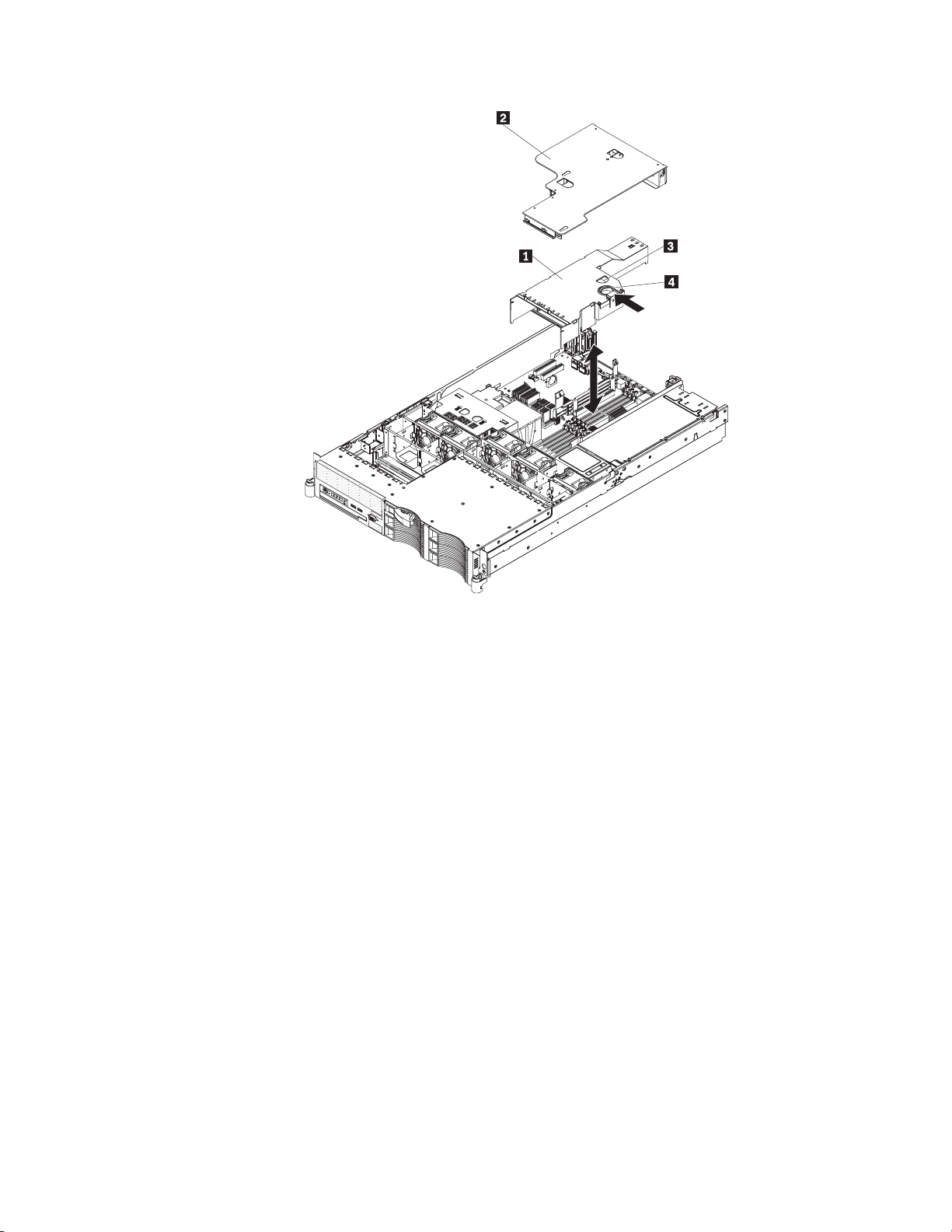
Installing a Remote Supervisor Adapter II SlimLine
An optional Remote Supervisor Adapter II SlimLine can be installed only in a
dedicated connector on the system board. After the Remote Supervisor Adapter II
SlimLine is installed, the systems-management Ethernet port on the rear of the
server is active.
Note: Earlier versions of the Remote Supervisor Adapter II SlimLine might not work
in this server. See http://www.lenovo.com/support/ for information about which
versions of the Remote Supervisor Adapter II SlimLine are supported.
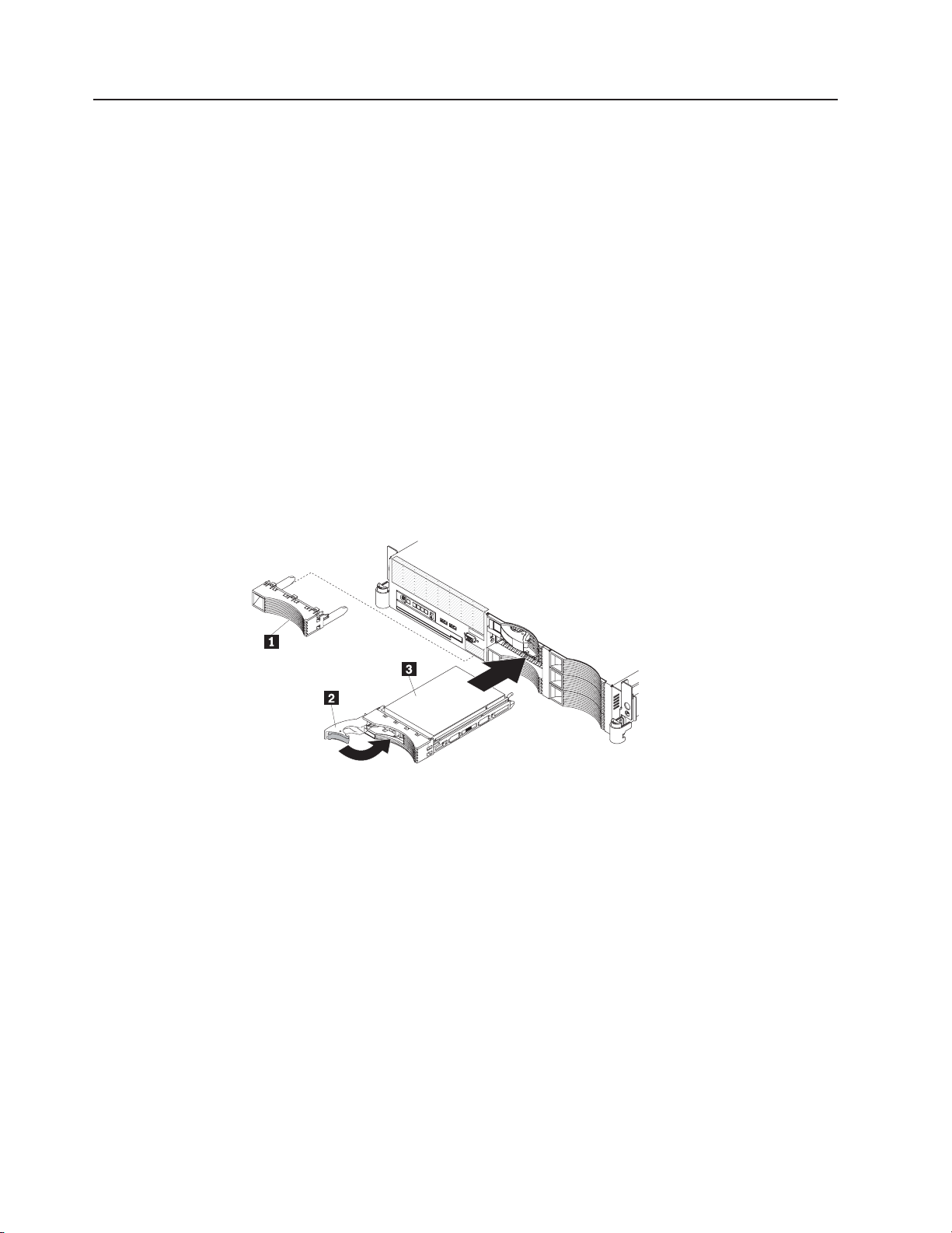
The following illustration shows how to install a Remote Supervisor Adapter II
SlimLine.
Chapter 2. Installing optional devices 27
Page 42

1 Retainer bracket 3 Remote Supervisor Adapter II
SlimLine
2 Connector 4 Latch bracket
To install a Remote Supervisor Adapter II SlimLine, complete the following steps:
1. Read the safety information that begins on page v and “Installation guidelines”
on page 7.
2. Turn off the server and peripheral devices and disconnect all power cords and
external cables.
Attention: In a dc power environment, only trained service personnel other
than Lenovo service technicians are authorized to connect or disconnect power
to the dc power supply. See the documentation that comes with each dc power
supply.
3. Remove the cover.
4. Remove the PCI riser-card assembly.
5. Align the keys on the Remote Supervisor Adapter II SlimLine connector with the
connector on the system board.
6. Slip the free end of the Remote Supervisor Adapter II SlimLine under the tab on
the retainer bracket, aligning the holes in the adapter with the posts on the
retainer bracket and latch bracket; then, press the adapter into the connector on
the system board and make sure that all tabs on the latch bracket secure the
adapter in place.
7. Replace the PCI riser-card assembly.
the documentation that comes with the Remote Supervisor Adapter II SlimLine
See
for information about installing the firmware and configuring the adapter. Create a
backup copy of the configuration so that if you have to replace the adapter in the
future, you can restore the configuration.
If you have other optional devices to install or remove, do so now. Otherwise, go to
“Completing the installation” on page 30.
28 ThinkServer RD120 Types 6444, 6445, 6446, and 6447: Installation Guide
Page 43

Replacing the ServeRAID SAS controller
A ServeRAID SAS controller can be installed only in a dedicated slot on the system
board. The server comes with a ServeRAID-8k-l SAS Controller installed.
Note: The ServeRAID-8k-l SAS Controller does not have a battery.
To replace the ServeRAID-8k-l SAS Controller with a ServeRAID-8k SAS Controller,
complete the following steps:
1. Read the safety information that begins on page v and the “Installation
guidelines” on page 7.
2. Turn off the server and peripheral devices and disconnect all power cords and
external cables (see “Turning off the server” on page 39).
Attention: In a dc power environment, only trained service personnel other
than Lenovo service technicians are authorized to connect or disconnect power
to the dc power supply. See the documentation that comes with each dc power
supply.
3. Remove the cover (see “Removing the cover” on page 9).
4. Remove the riser-card assembly and the air baffle over the DIMMs. See the
User Guide for more information.
5. Locate the ServeRAID-8k-l SAS controller on the system board.
Attention: To avoid breaking the retaining clips or damaging the connectors,
handle the clips gently.
6. Open the retaining clip on each end of the connector.
7. Lift the ServeRAID-8k-l SAS controller out of the connector.
8. Touch the static-protective package that contains the new ServeRAID-8k SAS
controller to any unpainted metal surface on the server. Then, remove the
ServeRAID-8k SAS controller from the package.
Chapter 2. Installing optional devices 29
Page 44

1 RAID controller 4 Battery mounting tabs
2 Battery cable 5 Battery mounting clips
3 Battery 6 Battery cable connector
9. Turn the new ServeRAID-8k SAS controller so that the keys on the bottom
edge align correctly with the connector.
10. Firmly press the ServeRAID-8k SAS controller straight down into the connector
by applying pressure on both ends of the controller simultaneously. The
retaining clips snap into the locked position when the controller is firmly seated
in the connector.
Note: If there is a gap between the controller and the retaining clips, the
controller has not been correctly installed. In this case, open the retaining clips
and remove the controller; then, reinsert the controller.
11. Remove the battery from the ServeRAID-8k SAS Controller package.
12. Slide the battery mounting tabs into the battery mounting clips on the server
wall that is next to the ServeRAID SAS controller connector.
13. Connect the battery to the ServeRAID-8k SAS Controller.
14. Replace the air baffle over the DIMMs. See the User Guide for more
information.
15. Replace the riser-card assembly.
you have other optional devices to install or remove, do so now. Otherwise, go to
If
“Completing the installation.”
Notes:
1. When you restart the server for the first time after you install a ServeRAID-8k
SAS controller, the monitor screen remains blank while the controller initializes
the battery. This might take a few minutes, after which the startup process
continues. This is a one-time occurrence.
Important: You must allow the initialization process to be completed. If you do
not, the battery pack will not work, and the server might not start.
The battery comes partially charged, at 30% or less of capacity. Run the server
for 4 to 6 hours to fully charge the controller battery. The LED just above the
battery on the controller remains lit until the battery is fully charged.
Until the battery is fully charged, the controller firmware sets the controller
cache to write-through mode; after the battery is fully charged, the controller
firmware re-enables write-back mode.
2. When you restart the server, you will be given the opportunity to import the
existing RAID configuration to the new ServeRAID SAS controller.
Completing the installation
To complete the installation, complete the following steps:
1. Install the cover. See “Installing the cover” on page 31 for more information.
2. Install the server in the rack cabinet. See the Rack Installation Instructions that
come with the server for detailed information about how to install the server in a
rack cabinet.
30 ThinkServer RD120 Types 6444, 6445, 6446, and 6447: Installation Guide
Page 45

Attention:
v Install the server only in a rack cabinet that has perforated doors.
v Do not leave open space above or below an installed server in your rack
Connect the cables and power cords.
3.
Attention: In a dc power environment, only trained service personnel other
than Lenovo service technicians are authorized to connect or disconnect power
to the dc power supply. See the documentation that comes with each dc power
supply.
See
4. Update the server configuration. See “Updating the server configuration” on
page 32 for more information.
Installing the cover
To install the cover, place it into position and slide it forward.
cabinet. To help prevent damage to server components, always install a filler
panel to cover the open space and to help ensure proper air circulation. See
the documentation that comes with the rack cabinet for more information.
“Connecting the cables” on page 31 for more information.
1 Cover-release latch
Connecting the cables
The following illustrations show the locations of the input and output connectors on
the front and rear of the server.
Front view
1 USB 5 connector 3 Video connector
Chapter 2. Installing optional devices 31
Page 46

2 USB 6 connector
Rear view
1 Power cord connector 7 USB connector 2
2 Systems-management Ethernet
8 USB connector 1
connector
3 Ethernet connector 9 Video connector
4 USB connector 4 10 Serial connector
5 USB connector 3 11 SAS connector
6 Ethernet connector 2
Attention: In a dc power environment, only trained service personnel other than
Lenovo service technicians are authorized to connect or disconnect power to the dc
power supply. See the documentation that comes with each dc power supply for
instructions and an illustration of the dc power supply.
You must turn off the server before you connect or disconnect cables from the
server.
See the documentation that comes with any external devices for additional cabling
instructions. It might be easier for you to route cables before you connect the
devices to the server.
Cable identifiers are printed on the cables that come with the server and optional
devices. Use these identifiers to connect the cables to the correct connectors.
Updating the server configuration
When you start the server for the first time after you add or remove an internal
optional device, external SAS device, or USB keyboard or mouse, you might
receive a message that the configuration has changed. The Configuration/Setup
Utility program starts automatically so that you can save the new configuration
settings. For more information, see Chapter 4, “Configuring the server,” on page 41.
Some optional devices have device drivers that you must install. See the
documentation that comes with each optional device for information about installing
device drivers.
The server comes with at least one microprocessor. If more than one
microprocessor is installed, the server can operate as a symmetric multiprocessing
(SMP) server. You might have to upgrade the operating system to support SMP. For
more information, see the operating-system documentation.
32 ThinkServer RD120 Types 6444, 6445, 6446, and 6447: Installation Guide
Page 47

If you have installed or removed a hard disk drive, see “Using the RAID
configuration programs” on page 44 for information about reconfiguring the disk
arrays.
If you have installed a Remote Supervisor Adapter SlimLine to manage the server
remotely, see the documentation comes with the adapter for information about
setting up, configuring, and using the adapter.
For information about configuring the integrated Gigabit Ethernet controllers, see
the User Guide.
Chapter 2. Installing optional devices 33
Page 48

34 ThinkServer RD120 Types 6444, 6445, 6446, and 6447: Installation Guide
Page 49

Chapter 3. Server controls, LEDs, and power
This section describes the controls and light-emitting diodes (LEDs) and how to turn
the server on and off.
Front view
The following illustration shows the controls, light-emitting diodes (LEDs), and
connectors on the front of the 3.5-inch model server.
1 Operator information panel 6 Hard disk drive status LED (amber)
2 USB 5 connector 7 Rack release latch
3 USB 6 connector 8 CD/DVD eject button
4 Video connector 9 CD/DVD drive activity LED
5 Hard disk drive activity LED (green) 10 Rack release latch
The following illustration shows the controls, light-emitting diodes (LEDs), and
connectors on the front of the 2.5-inch model server.
1 Operator information panel 7 Hard disk drive status LED (amber)
2 USB 5 connector 8 Rack release latch
3 USB 6 connector 9 CD/DVD eject button
4 Video connector 10 CD/DVD drive activity LED
5 Tape drive bay 11 Rack release latch
6 Hard disk drive activity LED (green)
Operator information panel: This panel contains controls, LEDs, and connectors.
The following illustration shows the controls, LEDs, and connectors on the operator
information panel.
© Lenovo 2008. Portions © IBM Corp. 2007. 35
Page 50

1 Power-on LED 5 System-error LED
2 Hard disk drive activity LED 6 System-locator LED
3 Information LED 7 Power-control button
4 Release latch
The following controls, LEDs, and connectors are on the operator information panel:
v Power-control button: Press this button to turn the server on and off manually.
v Power-on LED: When this LED is lit and not flashing, it indicates that the server
is turned on. When this LED is flashing, it indicates that the server is turned off
and still connected to a power source. When this LED is off, it indicates that
power is not present, or the power supply or the LED itself has failed.
Note: If this LED is off, it does not mean that there is no electrical power in the
server. The LED might be burned out. To remove all electrical power from the
server, you must disconnect the power cord from the electrical outlet.
Attention: In a dc power environment, only trained service personnel other than
Lenovo service technicians are authorized to connect or disconnect power to the
dc power supply. See the documentation that comes with each dc power supply.
v Hard disk drive activity LED: When this LED is flashing, it indicates that a hard
disk drive is in use.
v System-locator LED: Use this LED to visually locate the server among other
servers. You can use IBM Director to light this LED remotely.
v Information LED: When this LED is lit, it indicates that a noncritical event has
occurred. An LED on the light path diagnostics panel is also lit to help isolate the
error.
v System-error LED: When this LED is lit, it indicates that a system error has
occurred. An LED on the light path diagnostics panel is also lit to help isolate the
error.
v Release latch: Slide this latch to the left to access the light path diagnostics
panel, which is behind the operator information panel.
connectors: Connect a USB device, such as USB mouse, keyboard, or other
USB
USB device, to either of these connectors.
Video connector: Connect a monitor to this connector. The video connectors on
the front and rear of the server can be used simultaneously.
Hard disk drive activity LED: Each hot-swap hard disk drive has an activity LED.
When this LED is flashing, it indicates that the drive is in use.
Hard disk drive status LED: On some server models, each hot-swap hard disk
drive has a status LED. When this LED is lit, it indicates that the drive has failed.
When this LED is flashing slowly (one flash per second), it indicates that the drive is
36 ThinkServer RD120 Types 6444, 6445, 6446, and 6447: Installation Guide
Page 51

Rear view
being rebuilt as part of a RAID configuration. When the LED is flashing rapidly
(three flashes per second), it indicates that the controller is identifying the drive.
CD/DVD-eject button: Press this button to release a CD or DVD from the
CD-RW/DVD drive.
CD/DVD drive activity LED: When this LED is lit, it indicates that the CD-RW/DVD
drive is in use.
Rack release latches: Press these latches to release the server from the rack.
The following illustration shows the connectors and LEDs on the rear of the server.
Attention: In a dc power environment, see the documentation that comes with
the dc power supply for information about the power-supply LEDs.
1 Power cord connector 1 11 Ethernet connector 2
2 AC power LED 12 USB connector 2
3 DC power LED 13 USB connector 1
4 Power supply filler panel 14 Video connector
5 Systems-management Ethernet
15 System-error LED
connector
6 Ethernet activity LEDs 16 System-locator LED
7 Ethernet link LEDs 17 Power-on LED
8 Ethernet connector 1 18 Serial connector
9 USB connector 4 19 SAS connector
10 USB connector 3 20 Power supply 1
Power-cord connector (ac power supply only): Connect the power cord to this
connector.
Attention: In a dc power environment, only trained service personnel other than
Lenovo service technicians are authorized to connect or disconnect power to the dc
power supply. See the documentation that comes with each dc power supply.
AC power LED: Each hot-swap power supply has an ac power LED and a dc
power LED. When the ac power LED is lit, it indicates that sufficient power is
coming into the power supply through the power cord. During typical operation, both
the ac and dc power LEDs are lit. For any other combination of LEDs, see the
Hardware Maintenance Manual on the ThinkServer Documentation DVD.
DC power LED: Each hot-swap power supply has a dc power LED and an ac
power LED. When the dc power LED is lit, it indicates that the power supply is
Chapter 3. Server controls, LEDs, and power 37
Page 52

supplying adequate DC power to the system. During typical operation, both the ac
and dc power LEDs are lit. For any other combination of LEDs, see the Hardware
Maintenance Manual on the ThinkServer Documentation DVD.
Systems-management Ethernet connector: Use this connector to connect the
server to a network for systems-management information control. This connector is
active only if you have installed a Remote Supervisor Adapter II SlimLine, and it is
used only by the Remote Supervisor Adapter II SlimLine.
Ethernet activity LEDs: When these LEDs are lit, they indicate that the server is
transmitting to or receiving signals from the Ethernet LAN that is connected to the
Ethernet port.
Ethernet link LEDs: When these LEDs are lit, they indicate that there is an active
link connection on the 10BASE-T, 100BASE-TX, or 1000BASE-TX interface for the
Ethernet port.
Ethernet connectors: Use either of these connectors to connect the server to a
network.
USB connectors: Connect a USB device, such as USB mouse, keyboard, or other
USB device, to any of these connectors.
Video connector: Connect a monitor to this connector. The video connectors on
the front and rear of the server can be used simultaneously.
System-error LED: When this LED is lit, it indicates that a system error has
occurred. An LED on the light path diagnostics panel is also lit to help isolate the
error.
System-locator LED: Use this LED to visually locate the server among other
servers.
Power-on LED: When this LED is lit and not flashing, it indicates that the server is
turned on. When this LED is flashing, it indicates that the server is turned off and
still connected to a power source. When this LED is off, it indicates that power is
not present, or the power supply or the LED itself has failed.
Serial connector: Connect a 9-pin serial device to this connector. The serial port is
shared with the baseboard management controller (BMC). The BMC can take
control of the shared serial port to perform text console redirection and to redirect
serial traffic, using Serial over LAN (SOL).
SAS connector: Connect a serial-attached SCSI (SAS) device to this connector.
Server power features
When the server is connected to a power source but is not turned on, the operating
system does not run, and all core logic except for the service processor (the
baseboard management controller or optional Remote Supervisor Adapter II
SlimLine) is shut down; however, the server can respond to requests from the
service processor, such as a remote request to turn on the server. The power-on
LED flashes to indicate that the server is connected to power but is not turned on.
38 ThinkServer RD120 Types 6444, 6445, 6446, and 6447: Installation Guide
Page 53

Attention: In a dc power environment, only trained service personnel other than
Lenovo service technicians are authorized to connect or disconnect power to the dc
power supply. See the documentation that comes with each dc power supply.
Turning on the server
Approximately 5 seconds after the server is connected to power, the power-control
button becomes active, and one or more fans might start running to provide cooling
while the server is connected to power. You can turn on the server and start the
operating system by pressing the power-control button.
The server can also be turned on in any of the following ways:
v If a power failure occurs while the server is turned on, the server will restart
automatically when power is restored.
v If your operating system supports the Wake on LAN feature, the Wake on LAN
feature can turn on the server.
Note: When 4 GB or more of memory (physical or logical) is installed, some
memory is reserved for various system resources and is unavailable to the
operating system. The amount of memory that is reserved for system resources
depends on the operating system, the configuration of the server, and the
configured PCI options.
Turning off the server
When you turn off the server and leave it connected to power, the server can
respond to requests from the service processor, such as a remote request to turn
on the server. While the server remains connected to power, one or more fans
might continue to run. To remove all power from the server, you must disconnect it
from the power source.
Attention: In a dc power environment, only trained service personnel other than
Lenovo service technicians are authorized to connect or disconnect power to the dc
power supply. See the documentation that comes with each dc power supply.
Some operating systems require an orderly shutdown before you turn off the server.
See your operating-system documentation for information about shutting down the
operating system.
Statement 5:
CAUTION:
The power control button on the device and the power switch on the power
supply do not turn off the electrical current supplied to the device. The device
also might have more than one power cord. To remove all electrical current
from the device, ensure that all power cords are disconnected from the power
source.
Chapter 3. Server controls, LEDs, and power 39
Page 54

2
1
Attention: In a dc power environment, only trained service personnel other than
Lenovo service technicians are authorized to connect or disconnect power to the dc
power supply. See the documentation that comes with each dc power supply.
server can be turned off in any of the following ways:
The
v You can turn off the server from the operating system, if your operating system
supports this feature. After an orderly shutdown of the operating system, the
server will be turned off automatically.
v You can press the power-control button to start an orderly shutdown of the
operating system and turn off the server, if your operating system supports this
feature.
v If the operating system stops functioning, you can press and hold the
power-control button for more than 4 seconds to turn off the server.
v The service processor can turn off the server as an automatic response to a
critical system failure.
v You can turn off the server through a request from the service processor.
40 ThinkServer RD120 Types 6444, 6445, 6446, and 6447: Installation Guide
Page 55

Chapter 4. Configuring the server
Lenovo provides a number of programs to assist you with getting your server up
and running quickly.
v ThinkServer EasyStartup program
This program simplifies the process of installing the operating system and
devices drivers. It is on the ThinkServer ThinkServer EasyStartup DVD provided
with your server. For details, see “Using the ThinkServer EasyStartup program.”
v Configuration/Setup Utility program
This program enables you to configure hardware settings and preferences in the
BIOS. For details, see “Using the Configuration/Setup Utility program” on page
43
v RAID configuration programs
– Adaptec RAID (HOSTRaid) Configuration Utility program:
This program is part of the BIOS code on models that have an integrated
ServeRAID-8e (Adaptec HostRAID) controller.
– LSI Configuration Utility
This program is part of the BIOS code on models with an optional LSI storage
controller with RAID capability.
v Broadcom Gigabit Ethernet Utility program:
Use this program to configure the network as a startable (bootable) device or
specify where the network startup option is displayed in the startup sequence.
For additional information, see “Configuring the Gigabit Ethernet controllers” on
page 43.
v Baseboard management controller SMBridge management utility program:
Use these programs to configure the baseboard management controller,
download firmware updates, download SDR/FRU updates, and remotely manage
a network.
v ThinkServer EasyManage products
ThinkServer EasyManage Core Server and ThinkServer EasyManage Remote
Client work together to provide centralized hardware and software inventory
management and secure automated system management through a single
console. See “Using ThinkServer EasyManage products” on page 43.
For more information about these programs, see “Configuring the server” in the
User Guide on the ThinkServer Documentation DVD.
Using the ThinkServer EasyStartup program
The ThinkServer EasyStartup program simplifies the process of installing the
operating system and devices drivers by performing the following tasks:
v Detects installed hardware devices
v Guides you through the process of creating a response file
v Prepares the hard disk for installation
v Prompts you to insert the operating-system installation disc
v Initiates an unattended installation of the operating system and device drivers for
most adapters and devices
program is contained on the ThinkServer EasyUpdate disc provided with your
The
server. If you did not receive an ThinkServer EasyStartup DVD with your server,
© Lenovo 2008. Portions © IBM Corp. 2007. 41
Page 56

you can download an ISO image of the DVD from http://www.lenovo.com/support.
The program has a built-in help system and User Guide to answer any questions
you might have. The program also provides compatibility notes to help you
determine what server configurations and operating systems are supported by that
specific version of the program.
The ThinkServer EasyStartup program also enables you to save the response file
on a USB device or diskette for reuse, and an option that enables you to install an
operating systems using the saved response. This option is useful if you intend to
install the same operating system on similarly configured ThinkServer servers.
Notes:
1. If you intend to implement a RAID, make sure your storage controller or RAID
adapter is configured correctly before you use the ThinkServer EasyStartup
program to install the operating system.
2. If you are using any external storage devices or fiber channels, use the utilities
provided with the device. You also will have to provide the device drivers for
these devices and install them after the EasyStartup program finishes installing
the operating system.
3. The ThinkServer EasyStartup DVD requires that you have a DVD drive that is
configured as your first device in the startup sequence. Use the
Configuration/Setup Utility program to view or change your startup sequence.
See “Using the Configuration/Setup Utility program” on page 43.
4. To install an operating system, you need the operating system installation disc
(CD or DVD) and the associated product key, if one was provided.
start the ThinkServer EasyStartup DVD, do the following:
To
1. Insert the ThinkServer EasyStartup DVD and restart the server. If the
EasyStartup program does not start, see “EasyStartup problems” on page 64.
2. Follow the instructions on the screen and continue to the main interface.
3. When you arrive at the Home screen, do any of the following:
v Click Compatibility notes to view detailed information about the operating
systems and server configurations supported by that version of the
EasyStartup program.
v Click User Guide to view an overview of the various functions provided by
that version of the EasyStartup program.
v Click Hardware list to view a list of hardware detected by the ThinkServer
EasyStartup program.
v Click Install operating system to begin the process of creating a response file
and installing the operating system. As part of this procedure you will be
given the opportunity to include the ThinkServer EasyUpdate program and
the ThinkServer EasyManage products (ThinkServer EasyManage Core
Server or ThinkVantage EasyManage Remote Client) as part of the
installation process. You also can provide one or more command-line based
instructions to be run at the end of the operating system installation process.
Click About to view version information and legal notices.
use the ThinkServer EasyStartup DVD to install an operation system using a
To
preexisting response file, do the following:
1. Insert the ThinkServer EasyStartup DVD and restart the server. If the
EasyStartup program does not start, see “EasyStartup problems” on page 64.
2. Follow the instructions on the screen until you get to the Start option screen.
3. When the Start option screen is displayed, do the following:
42 ThinkServer RD120 Types 6444, 6445, 6446, and 6447: Installation Guide
Page 57

a. Insert the USB device or diskette that contains the response file.
b. Select Install the operating system using a preexisting response file.
c. Click OK.
4. Follow the remaining instructions on the screen to complete the procedure.
Using ThinkServer EasyManage products
ThinkServer EasyManage Core Server provides centralized hardware and software
inventory management and secure automated system management through a
single console. The ThinkServer EasyManage Agent enables other computers and
servers to be managed by the centralized console.
You can install the ThinkServer EasyManage Core Server program from the
ThinkServer EasyManage CD or you can download and install the program from
http://www.lenovo.com/support. After one instance of the ThinkServer EasyManage
Core Server has been installed, you can use the ThinkServer EasyManage Agent
installer to install the agent on other servers and clients on the network.
Also, the ThinkServer EasyStartup program provides an option to install these
products as part of the operating system installation process.
Using the Configuration/Setup Utility program
The Configuration/Setup Utility program is part of the BIOS. You can use it to
perform the following tasks:
v View configuration information
v View and change assignments for devices and I/O ports
v Set the date and time
v Set and change passwords
v Set and change the startup characteristics of the server and the order of startup
devices (startup-drive sequence)
v Set and change settings for advanced hardware features
v View and clear the error log
v Change interrupt request (IRQ) settings
v Resolve configuration conflicts
start the Configuration/Setup Utility program, complete the following steps:
To
1. Turn on the server.
2. When the message Press F1 for Configuration/Setup appears, press F1. If
an administrator password has been set, you must type the administrator
password to access the full Configuration/Setup Utility menu.
3. Follow the instructions on the screen.
Configuring the Gigabit Ethernet controllers
The Ethernet controllers are integrated on the system board. They provide an
interface for connecting to a 10 Mbps, 100 Mbps, or 1 Gbps network and provide
full-duplex (FDX) capability, which enables simultaneous transmission and reception
of data on the network. If the Ethernet ports in the server support auto-negotiation,
the controllers detect the data-transfer rate (10BASE-T, 100BASE-TX, or
1000BASE-T) and duplex mode (full-duplex or half-duplex) of the network and
automatically operate at that rate and mode.
Chapter 4. Configuring the server 43
Page 58

Note: The Ethernet controller for Ethernet connector 1 supports Serial over LAN
(SOL).
You do not have to set any jumpers or configure the controllers. However, you must
install a device driver to enable the operating system to address the controllers. For
device drivers and information about configuring the Ethernet controllers, see the
Broadcom NetXtreme II Gigabit Ethernet Software CD that comes with the server.
To find updated information about configuring the controllers, complete the following
steps.
Note: Changes are made periodically to the Lenovo Web site. The actual
procedure might vary slightly from what is described in this document.
1. Go to: http://www.lenovo.com/support.
2. Enter your product number (machine type and model number) or select Servers
from the Select your product list.
3. Select Servers from the Brand list.
4. From Family list, select ThinkServer RD120, and click Continue.
Using the RAID configuration programs
Use the IBM ServeRAID Configuration Utility program and ServeRAID Manager to
configure and manage redundant array of independent disks (RAID) arrays. Be sure
to use these programs as described in this document.
v Use the IBM ServeRAID Configuration Utility program to:
– Perform a low-level format on a hard disk drive
– View or change IDs for attached devices
– Set protocol parameters on hard disk drives
Use ServeRAID Manager to:
v
– Configure arrays
– View the RAID configuration and associated devices
– Monitor operation of the RAID controller
Consider
the following information when using the IBM ServeRAID Configuration
Utility program and ServeRAID Manager to configure and manage arrays:
v The ServeRAID-8k-l SAS controller that comes with the server supports only
RAID level-0, level-1, and level-10. You can replace it with a ServeRAID-8k SAS
controller that supports additional RAID levels.
v Hard disk drive capacities affect how you create arrays. The drives in an array
can have different capacities, but the ServeRAID controller treats them as if they
all have the capacity of the smallest hard disk drive.
v To help ensure signal quality, do not mix drives with different speeds and data
rates.
v To update the firmware and BIOS code for an optional ServeRAID SAS
controller, you must use the IBM ServeRAID Support CD that comes with the
ServeRAID option.
Using the IBM ServeRAID Configuration Utility program
Use the IBM ServeRAID Configuration Utility programs to perform the following
tasks:
v Configure a redundant array of independent disks (RAID) array
v View or change the RAID configuration and associated devices
44 ThinkServer RD120 Types 6444, 6445, 6446, and 6447: Installation Guide
Page 59

Starting the IBM ServeRAID Configuration Utility program
To start the IBM ServeRAID Configuration Utility program, complete the following
steps:
1. Turn on the server.
2. When the prompt <<< Press <CTRL><A> for IBM ServeRAID Configuration
Utility! >>> appears, press Ctrl+A. If you have set an administrator password,
you are prompted to type the password.
3. To select a choice from the menu, use the arrow keys.
4. Use the arrow keys to select the channel for which you want to change settings.
5. To change the settings of the selected items, follow the instructions on the
screen. Be sure to press Enter to save your changes.
IBM ServeRAID Configuration Utility menu choices
The following choices are on the IBM ServeRAID Configuration Utility menu:
v Array Configuration Utility
Select this choice to create, manage, or delete arrays, or to initialize drives.
v SerialSelect Utility
Select this choice to configure the controller interface definitions or to configure
the physical transfer and SAS address of the selected drive.
v Disk Utilities
Select this choice to format a disk or verify the disk media. Select a device from
the list and read the instructions on the screen carefully before making a
selection.
Using ServeRAID Manager
Use ServeRAID Manager, which is on the IBM ServeRAID Support CD, to perform
the following tasks:
v Configure a redundant array of independent disks (RAID) array
v Erase all data from a hard disk drive and return the disk to the factory-default
settings
v View the RAID configuration and associated devices
v Monitor the operation of the RAID controller
perform some tasks, you can run ServeRAID Manager as an installed program.
To
However, to configure the RAID controller and perform an initial RAID configuration
on the server, you must run ServeRAID Manager in Startable CD mode, as
described in the instructions in this section.
See the ServeRAID documentation on the IBM ServeRAID Support CD for
additional information about RAID technology and instructions for using ServeRAID
Manager to configure the RAID controller. Additional information about ServeRAID
Manager is also available from the Help menu. For information about a specific
object in the ServeRAID Manager tree, select the object and click Actions --> Hints
and tips.
Configuring the RAID controller
By running ServeRAID Manager in Startable CD mode, you can configure the RAID
controller before you install the operating system. The information in this section
assumes that you are running ServeRAID Manager in Startable CD mode.
Chapter 4. Configuring the server 45
Page 60

To run ServeRAID Manager in Startable CD mode, turn on the server; then, insert
the CD into the CD-RW/DVD drive. If ServeRAID Manager detects an unconfigured
controller and ready drives, the Configuration wizard starts.
In the Configuration wizard, you can select express configuration or custom
configuration. Express configuration automatically configures the controller by
grouping the first two physical drives in the ServeRAID Manager tree into an array
and creating a RAID level-1 logical drive. If you select custom configuration, you
can select the two physical drives that you want to group into an array and create a
hot-spare drive.
Using express configuration: To use express configuration, complete the
following steps:
1. In the ServeRAID Manager tree, click the controller.
2. Click Express configuration.
3. Click Next.
4. In the “Configuration summary” window, review the information. To change the
configuration, click Modify arrays.
5. Click Apply; when you are asked whether you want to apply the new
configuration, click Yes. The configuration is saved in the controller and in the
physical drives.
6. Exit from ServeRAID Manager and remove the CD from the CD-RW/DVD drive.
7. Restart the server.
custom configuration: To use custom configuration, complete the
Using
following steps:
1. In the ServeRAID Manager tree, click the controller.
2. Click Custom configuration.
3. Click Next.
4. In the “Create arrays” window, from the list of ready drives, select the drives
that you want to group into the array.
5. Click the (Add selected drives) icon to add the drives to the array.
6. If you want to configure a hot-spare drive, complete the following steps:
a. Click the Spares tab.
b. Select the physical drive that you want to designate as the hot-spare drive,
and click the (Add selected drives) icon.
7. Click Next.
8. Review the information in the “Configuration summary” window. To change the
configuration, click Back.
9. Click Apply; when you are asked whether you want to apply the new
configuration, click Yes. The configuration is saved in the controller and in the
physical drives.
10. Exit from ServeRAID Manager and remove the CD from the CD-RW/DVD
drive.
11. Restart the server.
Viewing the configuration
You can use ServeRAID Manager to view information about RAID controllers and
the RAID subsystem (such as arrays, logical drives, hot-spare drives, and physical
46 ThinkServer RD120 Types 6444, 6445, 6446, and 6447: Installation Guide
Page 61

drives). When you click an object in the ServeRAID Manager tree, information about
that object appears in the right pane. To display a list of available actions for an
object, click the object and click Actions.
Using the baseboard management controller
The baseboard management controller provides basic service-processor
environmental monitoring functions for the server. If an environmental condition
exceeds a threshold or if a system component fails, the baseboard management
controller lights LEDs to help you diagnose the problem and also records the error
in the BMC system event log.
The baseboard management controller also provides the following remote server
management capabilities through the OSA SMBridge management utility program:
v Command-line interface (IPMI Shell)
The command-line interface provides direct access to server management
functions through the IPMI protocol. Use the command-line interface to issue
commands to control the server power, view system information, and identify the
server. You can also save one or more commands as a text file and run the file
as a script.
v Serial over LAN
Establish a Serial over LAN (SOL) connection to manage servers from a remote
location. You can remotely view and change the BIOS settings, restart the server,
identify the server, and perform other management functions. Any standard Telnet
client application can access the SOL connection.
Important:
The server Ethernet ports are set to DHCP by default. In order to find
your BMC on an existing network, you will need to identify the server by the default
hostname. The default hostname for each server is the last 8 characters of the
BMC MAC address. The BMC MAC address can be found in the setup utility, on a
label on the system board, and on a tag hanging from the front of the server. Once
you have deployed your server, make sure that you remove the BMC MAC address
tag from the front of the server so that it does not impede airflow through the front
of the server.
Enabling and configuring SOL using the OSA SMBridge management utility program
To enable and configure the server for SOL by using the OSA SMBridge
management utility program, you must update and configure the BIOS code; update
and configure the baseboard management controller (BMC) firmware; update and
configure the Ethernet controller firmware; and enable the operating system for an
SOL connection.
BIOS update and configuration
To update and configure the BIOS code to enable SOL, complete the following
steps:
1. Update the BIOS code:
a. Download the latest version of the BIOS code from http://www.lenovo.com/
support/.
b. Update the BIOS code, following the instructions that come with the update
file that you downloaded.
Update the BMC firmware:
2.
Chapter 4. Configuring the server 47
Page 62

a. Download the latest version of the BMC firmware from http://
www.lenovo.com/support/.
b. Update the BMC firmware, following the instructions that come with the
update file that you downloaded.
Configure the BIOS settings:
3.
a. When you are prompted to start the Configuration/Setup Utility program,
restart the server and press F1.
b. Select Devices and I/O Ports; then, make sure that the values are set as
follows:
v Serial Port A: Auto-configure
v Serial Port B: Auto-configure
c. Select Remote Console Redirection; then, make sure that the values are
set as follows:
v Remote Console Active: Enabled
v Remote Console COM Port: COM 1
v Remote Console Baud Rate: 19200 or higher
v Remote Console Data Bits: 8
v Remote Console Parity: None
v Remote Console Stop Bits: 1
v Remote Console Text Emulation: ANSI
v Remote Console Keyboard Emulation: ANSI
v Remote Console Active After Boot: Enabled
v Remote Console Flow Control: Hardware
Press Esc twice to exit the Remote Console Redirection and Devices and
d.
I/O Ports sections of the Configuration/Setup Utility program.
e. Select Advanced Setup; then, select Baseboard Management Controller
(BMC) Settings.
f. Set BMC Serial Port Access Mode to Dedicated.
g. Press Esc twice to exit the Baseboard Management Controller (BMC)
Settings and Advanced Setup sections of the Configuration/Setup Utility
program.
h. Select Save Settings; then, press Enter.
i. Press Enter to confirm.
j. Select Exit Setup; then, press Enter.
k. Make sure that Yes, exit the Setup Utility is selected; then, press Enter.
Linux configuration
For SOL operation on the server, you must configure the Linux® operating system to
expose the Linux initialization (booting) process. This enables users to log in to the
Linux console through an SOL session and directs Linux output to the serial
console. See the documentation for your specific Linux operating-system type for
information and instructions.
Use one of the following procedures to enable SOL sessions for your Linux
operating system. You must be logged in as a root user to perform these
procedures.
Red Hat Enterprise Linux ES 4 configuration:
48 ThinkServer RD120 Types 6444, 6445, 6446, and 6447: Installation Guide
Page 63

Note: This procedure is based on a default installation of Red Hat Enterprise Linux
ES 4. The file names, structures, and commands might be different for other
versions of Red Hat Linux.
To configure the general Linux parameters for SOL operation when you are using
the Red Hat Enterprise Linux ES 4 operating system, complete the following steps.
Note: Hardware flow control prevents character loss during communication over a
serial connection. You must enable it when you are using a Linux operating system.
1. Add the following line to the end of the # Run gettys in standard runlevels
section of the /etc/inittab file. This enables hardware flow control and enables
users to log in through the SOL console.
7:2345:respawn:/sbin/agetty -h ttyS0 19200 vt102
2. Add the following line at the bottom of the /etc/securetty file to enable a user to
log in as the root user through the SOL console:
ttyS0
LILO configuration: If you are using LILO, complete the following steps:
1. Modify the /etc/lilo.conf file:
a. Add the following text to the end of the first default=linux line
-Monitor
b. Comment out the map=/boot/map line by adding a # at the beginning of this
line.
c. Comment out the message=/boot/message line by adding a # at the beginning
of this line.
d. Add the following line before the first image= line:
# This will allow you to only Monitor the OS boot via SOL
e. Add the following text to the end of the first label=linux line:
-Monitor
f. Add the following line to the first image= section. This enables SOL.
append="console=ttyS0,19200n8 console=tty1"
g. Add the following lines between the two image= sections:
# This will allow you to Interact with the OS boot via SOL
image=/boot/vmlinuz-2.4.9-e.12smp
label=linux-Interact
initrd=/boot/initrd-2.4.9-e.12smp.img
read-only
root=/dev/hda6
append="console=tty1 console=ttyS0,19200n8 "
The following examples show the original content of the /etc/lilo.conf file and the
content of this file after modification.
Chapter 4. Configuring the server 49
Page 64

Original /etc/lilo.conf contents
prompt
timeout=50
default=linux
boot=/dev/hda
map=/boot/map
install=/boot/boot.b
message=/boot/message
linear
image=/boot/vmlinuz-2.4.9-e.12smp
label=linux
initrd=/boot/initrd-2.4.9-e.12smp.img
read-only
root=/dev/hda6
image=/boot/vmlinuz-2.4.9-e.12
label=linux-up
initrd=/boot/initrd-2.4.9-e.12.img
read-only
root=/dev/hda6
50 ThinkServer RD120 Types 6444, 6445, 6446, and 6447: Installation Guide
Page 65

Modified /etc/lilo.conf contents
prompt
timeout=50
default=linux-Monitor
boot=/dev/hda
#map=/boot/map
install=/boot/boot.b
#message=/boot/message
linear
# This will allow you to only Monitor the OS boot via SOL
image=/boot/vmlinuz-2.4.9-e.12smp
label=linux-Monitor
initrd=/boot/initrd-2.4.9-e.12smp.img
read-only
root=/dev/hda6
append="console=ttyS0,19200n8 console=tty1"
# This will allow you to Interact with the OS boot via SOL
image=/boot/vmlinuz-2.4.9-e.12smp
label=linux-Interact
initrd=/boot/initrd-2.4.9-e.12smp.img
read-only
root=/dev/hda6
append="console=tty1 console=ttyS0,19200n8 "
image=/boot/vmlinuz-2.4.9-e.12
label=linux-up
initrd=/boot/initrd-2.4.9-e.12.img
read-only
root=/dev/hda6
2. Run the lilo command to store and activate the LILO configuration.
When the Linux operating system starts, a LILO boot: prompt is displayed instead
of the graphical user interface. Press Tab at this prompt to install all of the boot
options that are listed. To load the operating system in interactive mode, type
linux-Interact and then press Enter.
GRUB configuration: If you are using GRUB, complete the following steps to
modify the /boot/grub/grub.conf file:
1. Comment out the splashimage= line by adding a # at the beginning of this line.
2. Add the following line before the first title= line:
# This will allow you to only Monitor the OS boot via SOL
3. Append the following text to the first title= line:
SOL Monitor
4. Append the following text to the kernel/ line of the first title= section:
console=ttyS0,19200 console=tty1
5. Add the following five lines between the two title= sections:
# This will allow you to Interact with the OS boot via SOL
title Red Hat Linux (2.4.9-e.12smp) SOL Interactive
root (hd0,0)
Chapter 4. Configuring the server 51
Page 66

kernel /vmlinuz-2.4.9-e.12smp ro root=/dev/hda6 console=tty1
console=ttyS0,19200
initrd /initrd-2.4.9-e.12smp.img
Note: The entry that begins with kernel /vmlinuz is shown with a line break after
console=tty1. In your file, the entire entry must all be on one line.
The following examples show the original content of the /boot/grub/grub.conf file
and the content of this file after modification.
Original /boot/grub/grub.conf contents
#grub.conf generated by anaconda
#
# Note that you do not have to rerun grub after making changes to this file
# NOTICE: You have a /boot partition. This means that
# all kernel and initrd paths are relative to /boot/, eg.
# root (hd0,0)
# kernel /vmlinuz-version ro root=/dev/hda6
# initrd /initrd-version.img
#boot=/dev/hda
default=0
timeout=10
splashimage=(hd0,0)/grub/splash.xpm.gz
title Red Hat Enterprise Linux ES (2.4.9-e.12smp)
root (hd0,0)
kernel /vmlinuz-2.4.9-e.12smp ro root=/dev/hda6
initrd /initrd-2.4.9-e.12smp.img
title Red Hat Enterprise Linux ES-up (2.4.9-e.12)
root (hd0,0)
kernel /vmlinuz-2.4.9-e.12 ro root=/dev/hda6
initrd /initrd-2.4.9-e.12.img
52 ThinkServer RD120 Types 6444, 6445, 6446, and 6447: Installation Guide
Page 67

Modified /boot/grub/grub.conf contents
#grub.conf generated by anaconda
#
# Note that you do not have to rerun grub after making changes to this file
# NOTICE: You have a /boot partition. This means that
# all kernel and initrd paths are relative to /boot/, eg.
# root (hd0,0)
# kernel /vmlinuz-version ro root=/dev/hda6
# initrd /initrd-version.img
#boot=/dev/hda
default=0
timeout=10
# splashimage=(hd0,0)/grub/splash.xpm.gz
# This will allow you to only Monitor the OS boot via SOL
title Red Hat Enterprise Linux ES (2.4.9-e.12smp) SOL Monitor
root (hd0,0)
kernel /vmlinuz-2.4.9-e.12smp ro root=/dev/hda6 console=ttyS0,19200 console=tty1
initrd /initrd-2.4.9-e.12smp.img
# This will allow you to Interact with the OS boot via SOL
title Red Hat Linux (2.4.9-e.12smp) SOL Interactive
root (hd0,0)
kernel /vmlinuz-2.4.9-e.12smp ro root=/dev/hda6 console=tty1 console=ttyS0,19200
initrd /initrd-2.4.9-e.12smp.img
title Red Hat Enterprise Linux ES-up (2.4.9-e.12)
root (hd0,0)
kernel /vmlinuz-2.4.9-e.12 ro root=/dev/hda6
initrd /initrd-2.4.9-e.12.img
You must restart the Linux operating system after you complete these procedures
for the changes to take effect and to enable SOL.
SUSE SLES 9.0 configuration:
Note: This procedure is based on a default installation of SUSE Linux Enterprise
Server (SLES) 9.0. The file names, structures, and commands might be different for
other versions of SUSE Linux.
To configure the general Linux parameters for SOL operation when using the SLES
9.0 operating system, complete the following steps.
Note: Hardware flow control prevents character loss during communication over a
serial connection. You must enable it when using a Linux operating system.
1. Add the following line to the end of the # getty-programs for the normal
runlevels section of the /etc/inittab file. This enables hardware flow control and
enables users to log in through the SOL console.
7:2345:respawn:/sbin/agetty -h ttyS0 19200 vt102
2. Add the following line after the tty6 line at the bottom of the /etc/securetty file to
enable a user to log in as the root user through the SOL console:
ttyS0
3. Complete the following steps to modify the /boot/grub/menu.lst file:
Chapter 4. Configuring the server 53
Page 68

a. Comment out the gfxmenu line by adding a # in front of the word gfxmenu.
b. Add the following line before the first title line:
# This will allow you to only Monitor the OS boot via SOL
c. Append the following text to the first title line:
SOL Monitor
d. Append the following text to the kernel line of the first title section:
console=ttyS1,19200 console=tty0
e. Add the following four lines between the first two title sections:
# This will allow you to Interact with the OS boot via SOL
title linux SOL Interactive
kernel (hd0,1)/boot/vmlinuz root=/dev/hda2 acpi=oldboot vga=791
console=tty1 console=ttyS0,19200
initrd (hd0,1)/boot/initrd
The following examples show the original content of the /boot/grub/menu.lst
file and the content of this file after modification.
Original /boot/grub/menu.lst contents Notes
gfxmanu (hd0,1)/boot/message
color white/blue black/light-gray
default 0
timeout 8
title linux
kernel (hd0,1)/boot/vmlinuz root=/dev/hda2 acpi=oldboot vga=791 1
initrd (hd0,1)/boot/initrd
title floppy
root
chainloader +1
title failsafe
kernal (hd0,1)/boot/vmlinuz.shipped root=/dev/hda2 ide=nodma apm=off vga=normal nosmp 1
disableapic maxcpus=0 3
initrd (hd0,1)/boot/initrd.shipped
Note 1: The kernel line is shown with a line break. In your file, the entire entry must all be on one line.
Modified /boot/grub/menu.lst contents Notes
#gfxmanu (hd0,1)/boot/message
color white/blue black/light-gray
default 0
timeout 8
# This will allow you to only Monitor the OS boot via SOL
title linux SOL Monitor
kernel (hd0,1)/boot/vmlinuz root=/dev/hda2 acpi=oldboot vga=791 console=ttyS1,19200 1
console=tty1
initrd (hd0,1)/boot/initrd
# This will allow you to Interact with the OS boot via SOL
title linux SOL Interactive
kernel (hd0,1)/boot/vmlinuz root=/dev/hda2 acpi=oldboot vga=791 console=tty1 console=ttyS0,19200
initrd (hd0,1)/boot/initrd
title floppy
54 ThinkServer RD120 Types 6444, 6445, 6446, and 6447: Installation Guide
Page 69

Modified /boot/grub/menu.lst contents Notes
root
chainloader +1
title failsafe
kernel (hd0,1)/boot/vmlinuz.shipped root=/dev/hda2 ide=nodma apm=off vga=normal nosmp 1
disableapic maxcpus=0 3
initrd (hd0,1)/boot/initrd.shipped
Note 1: The kernel line is shown with a line break. In your file, the entire entry must all be on one line.
You must restart the Linux operating system after you complete these procedures
for the changes to take effect and to enable SOL.
Microsoft Windows 2003 Standard Edition configuration
Note: This procedure is based on a default installation of the Microsoft® Windows
2003 operating system.
To configure the Windows 2003 operating system for SOL operation, complete the
following steps. You must be logged in as a user with administrator access to
perform this procedure.
1. Complete the following steps to determine which boot entry ID to modify:
a. Type bootcfg at a Windows command prompt; then, press Enter to display
the current boot options for your server.
b. In the Boot Entries section, locate the boot entry ID for the section with an
OS friendly name of Windows Server 2003, Standard. Write down the boot
entry ID for use in the next step.
To enable the Microsoft Windows Emergency Management System (EMS), at a
2.
Windows command prompt, type
bootcfg /EMS ON /PORT COM1 /BAUD 19200 /ID boot_id
where boot_id is the boot entry ID from step 1b; then, press Enter.
3. Complete the following steps to verify that the EMS console is redirected to the
COM1 serial port:
a. Type bootcfg at a Windows command prompt; then, press Enter to display
the current boot options for your server.
b. Verify the following changes to the bootcfg settings:
v In the Boot Loader Settings section, make sure that redirect is set to
COM1 and that redirectbaudrate is set to 19200.
v In the Boot Entries section, make sure that the OS Load Options: line
has /redirect appended to the end of it.
following examples show the original bootcfg program output and the output
The
after modification.
®
Chapter 4. Configuring the server 55
Page 70

Original bootcfg program output
Boot Loader Settings
----------------------------
timeout: 30
default: multi(0)disk(0)rdisk(0)partition(1)\WINDOWS
Boot Entries
----------------
Boot entry ID: 1
OS Friendly Name: Windows Server 2003, Standard
Path: multi(0)disk(0)rdisk(0)partition(1)\WINDOWS
OS Load Options: /fastdetect
Modified bootcfg program output
Boot Loader Settings
----------------------------
timeout: 30
default: multi(0)disk(0)rdisk(0)partition(1)\WINDOWS
redirect: COM1
redirectbaudrate: 19200
Boot Entries
----------------
Boot entry ID: 1
OS Friendly Name: Windows Server 2003, Standard
Path: multi(0)disk(0)rdisk(0)partition(1)\WINDOWS
OS Load Options: /fastdetect /redirect
You must restart the Windows 2003 operating system after you complete this
procedure for the changes to take effect and to enable SOL.
Installing the OSA SMBridge management utility program
Important: To obtain maximum benefit from the OSA SMBridge management utility
program, install and load the program before problems occur.
To install the OSA SMBridge management utility program on a server running a
Windows operating system, complete the following steps:
1. Go to http://www.lenovo.com/support/ and download the utility program and
create the OSA BMC Management Utility CD.
2. Insert the OSA BMC Management Utility CD into the drive. The InstallShield
wizard starts, and a window similar to that shown in the following illustration
opens.
56 ThinkServer RD120 Types 6444, 6445, 6446, and 6447: Installation Guide
Page 71

3. Follow the prompts to complete the installation.
The installation program prompts you for a TCP/IP port number and an IP
address. Specify an IP address, if you want to limit the connection requests that
will be accepted by the utility program. To accept connections from any server,
type INADDR_ANY as the IP address. Also specify the port number that the utility
program will use. These values will be recorded in the smbridge.cfg file for the
automatic startup of the utility program.
install the OSA SMBridge management utility program on a server running a
To
Linux operating system, complete the following steps. You must be logged in as a
root user to perform these procedures.
1. Go to http://www.lenovo.com/support/. Download the utility program and create
the OSA BMC Management Utility CD.
2. Insert the OSA BMC Management Utility CD into the drive.
3. Type mount/mnt/cdrom.
4. Locate the directory where the installation RPM package is located and type
cd/mnt/cdrom.
5. Type the following command to run the RPM package and start the installation:
rpm -ivh smbridge-2.0-xx.rpm
where xx is the release level being installed.
6. Follow the prompts to complete the installation. When the installation is
complete, the utility copies files to the following directories:
/etc/init.d/SMBridge
/etc/smbridge.cfg
/usr/sbin/smbridged
/var/log/smbridge/Liscense.txt
/var/log/smbridge/Readme.txt
Chapter 4. Configuring the server 57
Page 72

The utility starts automatically when the server is started. You can also locate the
/ect/init.d directory to start the utility and use the following commands to manage
the utility:
smbridge status
smbridge start
smbridge stop
smbridge restart
Using the baseboard management controller utility programs
Use the baseboard management controller utility programs to configure the
baseboard management controller, download firmware updates and SDR/FRU
updates, and remotely manage a network.
Using the baseboard management controller configuration utility program
Use the baseboard management controller configuration utility program to view or
change the baseboard management controller configuration settings. You can also
use the utility program to save the configuration to a file for use on multiple servers.
Note: You must attach an optional USB diskette drive to the server to run this
program.
To start the baseboard management controller configuration utility program,
complete the following steps:
1. Insert the configuration utility diskette into the diskette drive and restart the
server.
2. From a command-line prompt, type bmc_cfg and press Enter.
3. Follow the instructions on the screen.
Using the baseboard management controller firmware update utility program
Use the baseboard management controller firmware update utility program to
download and apply a baseboard management controller firmware update and
SDR/FRU data update. The firmware update utility program updates the baseboard
management controller firmware and SDR/FRU data only and does not affect any
device drivers.
Note: To ensure proper server operation, be sure to update the server baseboard
management controller firmware before you update the BIOS code.
To update the firmware, if the Linux or Windows operating-system update package
is available from the World Wide Web and you have obtained the applicable update
package, follow the instructions that come with the update package.
Using the OSA SMBridge management utility program
Use the OSA SMBridge management utility program to remotely manage and
configure a network. The utility program provides the following remote management
capabilities:
58 ThinkServer RD120 Types 6444, 6445, 6446, and 6447: Installation Guide
Page 73

v CLI (command-line interface) mode
Use CLI mode to remotely perform power-management and system identification
control functions over a LAN or serial port interface from a command-line
interface. Use CLI mode also to remotely view the BMC system event log.
Use the following commands in CLI mode:
– identify
Control the system-locator LED on the front of the server.
– power
Turn the server on and off remotely.
– sel
Perform operations with the BMC system event log.
– sysinfo
Display general system information that is related to the server and the
baseboard management controller.
v Serial over LAN
Use the Serial over LAN capability to remotely perform control and management
functions over a Serial over LAN (SOL) network. You can also use SOL to
remotely view and change the server BIOS settings.
At a command prompt, type telnet localhost 623 to access the SOL network.
Type help at the smbridge> prompt for more information.
Use the following commands in an SOL session:
– connect
Connect to the LAN. Type connect -ip ip_address -u username -p
password.
– identify
Control the system-locator LED on the front of the server.
– power
Turn the server on and off remotely.
– reboot
Force the server to restart.
– sel get
Display the BMC system event log.
– sol
Configure the SOL function.
– sysinfo
Display system information that is related to the server and the globally
unique identifier (GUID).
Chapter 4. Configuring the server 59
Page 74

60 ThinkServer RD120 Types 6444, 6445, 6446, and 6447: Installation Guide
Page 75

Chapter 5. Solving problems
This chapter provides basic troubleshooting information to help you solve some
common problems that might occur while you are setting up the server.
If you cannot locate and correct the problem using the information in this chapter,
see Appendix A, “Getting help and technical assistance,” on page 81, the Hardware
Maintenance Manual on the ThinkServer Documentation DVD.
Diagnostic tools overview
The following tools are available to help you diagnose and solve hardware-related
problems:
v POST beep codes
The power-on self-test beep codes indicate the detection of a problem.
– One beep indicates successful completion of POST, with no errors.
– More than one beep indicates that POST detected a problem. Error messages
also appear during startup if POST detects a hardware-configuration problem.
See “POST beep codes” and the Hardware Maintenance Manual on the
ThinkServer Documentation DVD for more information.
Diagnostics DVD
v
The Diagnostics DVD provided with your server contains the diagnostic programs
for testing the major components of the server. For additional information about
the Diagnostics DVD, see the Hardware Maintenance Manual on the ThinkServer
Documentation DVD.
v Troubleshooting tables
These tables list problem symptoms and steps to correct the problems. See
“Troubleshooting tables” on page 65 for more information.
v Diagnostic programs and error messages
The system diagnostic programs are provided in ROM. These programs test the
major components of the server. See the Hardware Maintenance Manual on the
ThinkServer Documentation DVD
v Light path diagnostics
Use light path diagnostics to diagnose system errors quickly. See “Light path
diagnostics” on page 77 for more information.
POST beep codes
POST emits one beep to signal successful completion. If POST detects a problem
during startup, other beep codes might occur. Use the following beep code
descriptions to help diagnose and solve problems that are detected during startup.
Note: See the Hardware Maintenance Manual on the ThinkServer Documentation
DVD for more information about the POST beep codes.
beep
One
POST was completed successfully without finding any errors.
One long beep and two short beeps
A video error has occurred, and the BIOS cannot initialize the monitor
screen to display additional information.
© Lenovo 2008. Portions © IBM Corp. 2007. 61
Page 76

Other beep codes
See the Hardware Maintenance Manual on the ThinkServer Documentation
DVD for information about other beep codes.
62 ThinkServer RD120 Types 6444, 6445, 6446, and 6447: Installation Guide
Page 77

POST error codes
The following table provides an abbreviated list of the error codes that might appear
during POST. See the Hardware Maintenance Manual on the ThinkServer
Documentation DVD for more information about the POST error codes. To check for
updated technical information, complete the following steps.
Note:
procedure might vary slightly from what is described in this document.
1. Go to: http://www.lenovo.com/support.
2. Enter your product number (machine type and model number) or select Servers
3. Select Servers from the Brand list.
4. From Family list, select ThinkServer RD120, and click Continue.
5. Click User's guides and manuals for documentation.
Changes are made periodically to the Lenovo Web site. The actual
from the Select your product list.
Table 7. Abbreviated list of POST error messages
POST
message
161 The real-time clock
162 A device configuration
Failing device or
problem found Suggested action
battery has failed.
1. Reseat the battery.
2. Replace the battery or call for service.
v Run the Configuration/Setup Utility program,
has changed.
select Load Default Settings, and save the
settings.
v Make sure that optional devices are turned on
and installed correctly.
163 The time of day has
not been set.
289 A failing DIMM was
disabled.
301, 303 Keyboard and
keyboard controller
Run the Configuration/Setup Utility program and set
the date and time.
Make sure that the DIMMs are supported by the
server and that they are installed correctly.
Make sure that the keyboard cable is connected
and that nothing is resting on the keyboard keys.
1810 PCI device error Make sure that all PCI adapters are installed
correctly. In the Configuration/Setup Utility program,
make sure that all PCI devices are enabled.
Disable option ROMs and integrated devices that
are not needed and set the PCI device boot priority
to ensure that the boot device option ROM is able
to load.
1962 POST could not find
Install an operating system.
an operating system.
00019xxx Microprocessor x is
not functioning or
failed the built-in
Make sure that microprocessor x is installed
correctly. (Trained service technician only) If the
problem remains, replace microprocessor x.
self-test.
012980xx
Data for
Download and install the latest level of BIOS code.
microprocessor x
012981xx
Chapter 5. Solving problems 63
Page 78

EasyStartup problems
Table 8. ThinkServer EasyStartup DVD
v Follow the suggested actions in the order in which they are listed in the Action Column until the problem
is resolved.
v See the Hardware Maintenance Manual on the ThinkServer Documentation DVD to determine which
components are customer replaceable units (CRU’s) and which fields are field replacable units (FRU’s).
v If an action step is preceded by “(Trained service technician only),” that step must be performed only by a
trained service technician.
Symptom Action
The ThinkServer
EasyStartup DVD will not
start.
The ServeRAID Manager
program cannot view all
installed drives, or the
operating system cannot
be installed.
The operating-system
installation program
continuously loops.
The EasyStartup
program will not start the
operating-system media.
The operating system
cannot be installed; the
option is not available.
v Make sure that the server supports the EasyStartup program and has a startable
(bootable) CD or DVD drive.
v If the startup (boot) sequence settings have been changed, make sure that the CD or
DVD drive is first in the startup sequence.
v If more than one CD or DVD drive is installed, make sure that only one drive is set as
the primary drive. Start the CD from the primary drive.
v Make sure that the hard disk drive is connected correctly.
v Make sure that the SAS hard disk drive cables are securely connected.
Make more space available on the hard disk.
Make sure that the operating-system media is supported by the EasyStartup program.
See the Lenovo Support Web site for a list of supported operating-system versions.
Make sure that the server supports the operating-system. If it does, either no logical drive
is defined (RAID servers), or the EasyStartup program is not installed. Run the
EasyStartup program and make sure that setup is complete.
64 ThinkServer RD120 Types 6444, 6445, 6446, and 6447: Installation Guide
Page 79

Troubleshooting tables
Use the troubleshooting tables to find solutions to problems that have identifiable
symptoms. See the Hardware Maintenance Manual on the ThinkServer
Documentation DVD for more detailed troubleshooting information. If you cannot
find the problem in these tables, run the diagnostic programs (see “Running the
diagnostic programs” in the Hardware Maintenance Manual).
If you have just added new software or a new optional device and the server is not
working, complete the following steps before using the troubleshooting tables:
1. Check the light path diagnostics LEDs on the operator information panel (see
“Light path diagnostics” on page 77).
2. Remove the software or device that you just added.
3. Run the diagnostic tests to determine whether the server is running correctly.
4. Reinstall the new software or new device.
CD-RW/DVD drive problems
v Follow the suggested actions in the order in which they are listed in the Action column until the problem
is solved.
v See the parts listing in the Hardware Maintenance Manual to determine which components are customer
replaceable units (CRU) and which components are field replaceable units (FRU).
v If an action step is preceded by “(Trained service technician only),” that step must be performed only by a
trained service technician.
Symptom Action
The CD-RW/DVD drive is not
recognized.
The CD-RW/DVD drive is not
working correctly.
1. Make sure that:
v The IDE channel to which the CD-RW/DVD drive is attached (primary) is
enabled in the Configuration/Setup Utility program.
v All cables and jumpers are installed correctly.
v The signal cable and connector are not damaged and the connector pins are
not bent.
v All damaged parts are repaired or replaced.
v The correct device driver is installed for the CD-RW/DVD drive.
Run the CD-RW/DVD drive diagnostic programs.
2.
3. Reseat the following components:
a. CD-RW/DVD drive
b. IDE/Ultrabay Enhanced (UBE) interposer card cable
Replace the components listed in step 3 one at a time, in the order shown,
4.
restarting the server each time.
1. Clean the CD or DVD.
2. Run the CD-RW/DVD drive diagnostic programs.
3. Check the connector and signal cable for bent pins or damage.
4. Replace any damaged parts.
5. Reseat the CD-RW/DVD drive.
6. Replace the CD-RW/DVD drive.
Chapter 5. Solving problems 65
Page 80

v Follow the suggested actions in the order in which they are listed in the Action column until the problem
is solved.
v See the parts listing in the Hardware Maintenance Manual to determine which components are customer
replaceable units (CRU) and which components are field replaceable units (FRU).
v If an action step is preceded by “(Trained service technician only),” that step must be performed only by a
trained service technician.
Symptom Action
The CD-RW/DVD drive tray is
not working.
1. Make sure that the server is turned on.
2. Insert the end of a straightened paper clip into the manual tray-release
opening.
3. Reseat the CD-RW/DVD drive.
4. Replace the CD-RW/DVD drive.
General problems
v Follow the suggested actions in the order in which they are listed in the Action column until the problem
is solved.
v See the parts listing in the Hardware Maintenance Manual to determine which components are customer
replaceable units (CRU) and which components are field replaceable units (FRU).
v If an action step is preceded by “(Trained service technician only),” that step must be performed only by a
trained service technician.
Symptom Action
A cover lock is broken, an LED
is not working, or a similar
problem has occurred.
If the part is a CRU, replace it. If the part is a FRU, the part must be replaced by a
trained service technician.
Hard disk drive problems
v Follow the suggested actions in the order in which they are listed in the Action column until the problem
is solved.
v See the parts listing in the Hardware Maintenance Manual to determine which components are customer
replaceable units (CRU) and which components are field replaceable units (FRU).
v If an action step is preceded by “(Trained service technician only),” that step must be performed only by a
trained service technician.
Symptom Action
Not all drives are recognized by
the hard disk drive diagnostic
test (the Fixed Disk test).
The server stops responding
during the hard disk drive
diagnostic test.
A hard disk drive was not
detected while the operating
system was being started.
A hard disk drive passes the
diagnostic Fixed Disk Test, but
the problem remains.
Remove the drive that is indicated by the diagnostic tests; then, run the hard disk
drive diagnostic test again. If the remaining drives are recognized, replace the drive
that you removed with a new one.
Remove the hard disk drive that was being tested when the server stopped
responding, and run the diagnostic test again. If the hard disk drive diagnostic test
runs successfully, replace the drive that you removed with a new one.
Reseat all hard disk drives and cables; then, run the hard disk drive diagnostic
tests again.
Run the diagnostic SCSI Attached Disk Test.
66 ThinkServer RD120 Types 6444, 6445, 6446, and 6447: Installation Guide
Page 81

Intermittent problems
v Follow the suggested actions in the order in which they are listed in the Action column until the problem
is solved.
v See the parts listing in the Hardware Maintenance Manual to determine which components are customer
replaceable units (CRU) and which components are field replaceable units (FRU).
v If an action step is preceded by “(Trained service technician only),” that step must be performed only by a
trained service technician.
Symptom Action
A problem occurs only
occasionally and is difficult to
diagnose.
The server resets (restarts)
occasionally
1. Make sure that:
v All cables and cords are connected securely to the rear of the server and
attached devices.
Attention: In a dc power environment, only trained service personnel
other than Lenovo service technicians are authorized to connect or
disconnect power to the dc power supply. See the documentation that comes
with each dc power supply.
v When the server is turned on, air is flowing from the fan grille. If there is no
airflow, the fans are not working. This can cause the server to overheat and
shut down.
Check the system event/error log or BMC system event log (see “Error Logs” in
2.
the Hardware Maintenance Manual).
1. If the reset occurs during POST and the POST watchdog timer is enabled (click
Advanced Setup --> Baseboard Management Controller (BMC) Setting -->
BMC Post Watchdog in the Configuration/Setup Utility program to see the
POST watchdog setting), make sure that sufficient time is allowed in the
watchdog timeout value (BMC POST Watchdog Timeout). See the User Guide
for information about the settings in the Configuration/Setup Utility program.
If the server continues to reset during POST, see the “POST” and “Diagnostic
programs” sections in the Hardware Maintenance Manual.
2. If the reset occurs after the operating system starts, disable any automatic
server restart (ASR) utilities, such as the IBM Automatic Server Restart IPMI
Application for Windows, or ASR devices that may be installed.
Note: ASR utilities operate as operating-system utilities and are related to the
IPMI device driver.
If the reset continues to occur after the operating system starts, the operating
system might have a problem; see “Software problems” on page 76.
3. If neither condition applies, check the system event/error log or BMC system
event log (see “Error Logs” in the Hardware Maintenance Manual).
Chapter 5. Solving problems 67
Page 82

USB keyboard, mouse, or pointing-device problems
v Follow the suggested actions in the order in which they are listed in the Action column until the problem
is solved.
v See the parts listing in the Hardware Maintenance Manual to determine which components are customer
replaceable units (CRU) and which components are field replaceable units (FRU).
v If an action step is preceded by “(Trained service technician only),” that step must be performed only by a
trained service technician.
Symptom Action
All or some keys on the
keyboard do not work.
The USB mouse or USB
pointing device does not work.
1. If you have installed a USB keyboard, run the Configuration/Setup Utility
program and enable keyboardless operation to prevent the POST error
message 301 from being displayed during startup.
2. See http://www.lenovo.com/accessories for keyboard compatibility.
3. Make sure that:
v The keyboard cable is securely connected.
v The server and the monitor are turned on.
Move the keyboard cable to a different USB connector.
4.
5. Replace the following components one at a time, in the order shown, restarting
the server each time:
a. Keyboard
b. (Only if the problem occurred with a front USB connector) Internal USB
cable
c. (Trained service technician only) System board
1. Make sure that:
v The mouse is compatible with the server. See http://www.lenovo.com/
accessories.
v The mouse or pointing-device USB cable is securely connected to the
server, and the device drivers are installed correctly.
v The server and the monitor are turned on.
If a USB hub is in use, disconnect the USB device from the hub and connect it
2.
directly to the server.
3. Move the mouse or pointing device cable to another USB connector.
4. Replace the following components one at a time, in the order shown, restarting
the server each time:
a. Mouse or pointing device
b. (Only if the problem occurred with a front USB connector) Internal USB
cable
c. (Trained service technician only) System board
68 ThinkServer RD120 Types 6444, 6445, 6446, and 6447: Installation Guide
Page 83

Memory problems
v Follow the suggested actions in the order in which they are listed in the Action column until the problem
is solved.
v See the parts listing in the Hardware Maintenance Manual to determine which components are customer
replaceable units (CRU) and which components are field replaceable units (FRU).
v If an action step is preceded by “(Trained service technician only),” that step must be performed only by a
trained service technician.
Symptom Action
The amount of system memory
that is displayed is less than the
amount of installed physical
memory.
Multiple rows of DIMMs in a
branch are identified as failing.
1. Make sure that:
v No error LEDs are lit on the operator information panel.
v Memory mirroring or memory sparing does not account for the discrepancy.
v The memory modules are seated correctly.
v You have installed the correct type of memory (see “Installing a memory
module” on page 10).
v If you changed the memory, you updated the memory configuration in the
Configuration/Setup Utility program.
v All banks of memory are enabled. The server might have automatically
disabled a memory bank when it detected a problem, or a memory bank
might have been manually disabled.
Check the POST error log for error message 289:
2.
v If a DIMM was disabled by a system-management interrupt (SMI), replace
the DIMM.
v If a DIMM was disabled by the user or by POST, run the Configuration/Setup
Utility program and enable the DIMM.
Run memory diagnostics (see “Running the diagnostic programs” in the
3.
Hardware Maintenance Manual).
4. Make sure that there is no memory mismatch when the server is at the
minimum memory configuration (two 512 MB DIMMs).
5. Add one pair of DIMMs at a time, making sure that the DIMMs in each pair are
matching. Install the DIMMs in the sequence that is described in “Installing a
memory module” on page 10.
6. Reseat the DIMMs.
7. Replace the following components one at a time, in the order shown, restarting
the server each time:
a. DIMMs
b. (Trained service technician only) System board
1. Reseat the DIMMs; then, restart the server.
2. Replace the lowest-numbered DIMM pair of those that are identified; then,
restart the server. Repeat as necessary.
3. (Trained service technician only) Replace the system board.
Chapter 5. Solving problems 69
Page 84

Microprocessor problems
v Follow the suggested actions in the order in which they are listed in the Action column until the problem
is solved.
v See the parts listing in the Hardware Maintenance Manual to determine which components are customer
replaceable units (CRU) and which components are field replaceable units (FRU).
v If an action step is preceded by “(Trained service technician only),” that step must be performed only by a
trained service technician.
Symptom Action
The server emits a continuous
beep during POST, indicating
that the microprocessor is not
working correctly.
1. Correct any errors that are indicated by the LEDs (see “Light path diagnostics
LEDs” in the Hardware Maintenance Manual).
2. Make sure that the server supports all the microprocessors and that the
microprocessors match in speed and cache size.
3. (Trained service technician only) Make sure that microprocessor 1 is seated
correctly.
4. Reseat the following components:
a. (Trained service technician only) Microprocessors
b. VRM, if microprocessor 2 is installed
(Trained service technician only) Replace the microprocessors.
5.
70 ThinkServer RD120 Types 6444, 6445, 6446, and 6447: Installation Guide
Page 85

Monitor problems
Some Lenovo monitors have their own self-tests. If you suspect a problem with your
monitor, see the documentation that comes with the monitor for instructions for
testing and adjusting the monitor. If you cannot diagnose the problem, call for
service.
v Follow the suggested actions in the order in which they are listed in the Action column until the problem
is solved.
v See the parts listing in the Hardware Maintenance Manual to determine which components are customer
replaceable units (CRU) and which components are field replaceable units (FRU).
v If an action step is preceded by “(Trained service technician only),” that step must be performed only by a
trained service technician.
Symptom Action
Testing the monitor
The screen is blank.
1. Make sure that the monitor cables are firmly connected.
2. Try using the other video port.
3. Try using a different monitor on the server, or try testing the monitor on a
different server.
4. Run the diagnostic programs (see the Hardware Maintenance Manual). If the
monitor passes the diagnostic programs, the problem might be a video device
driver.
5. Reseat the Remote Supervisor Adapter II SlimLine (if one is present).
6. Replace the following components one at a time, in the order shown, restarting
the server each time:
a. Remote Supervisor Adapter II SlimLine (if one is present)
b. (Trained service technician only) System board
1. If the server is attached to a KVM switch, bypass the KVM switch to eliminate it
as a possible cause of the problem: connect the monitor cable directly to the
correct connector on the rear of the server.
2. Make sure that:
v The server is turned on. If there is no power to the server, see “Power
problems” on page 73.
v The monitor cables are connected correctly.
v The monitor is turned on and the brightness and contrast controls are
adjusted correctly.
v No beep codes sound when the server is turned on.
Important:
In some memory configurations, the 3-3-3 beep code might sound
during POST, followed by a blank monitor screen. If this occurs and the Boot
Fail Count option in the Start Options of the Configuration/Setup Utility
program is enabled, you must restart the server three times to reset the
configuration settings to the default configuration (the memory connector or
bank of connectors enabled).
3. Make sure that the correct server is controlling the monitor, if applicable.
4. Make sure that damaged BIOS code is not affecting the video; see the
Hardware Maintenance Manual for information about recovering from a BIOS
failure.
5. See the Hardware Maintenance Manual for information about solving
undetermined problems.
Chapter 5. Solving problems 71
Page 86

v Follow the suggested actions in the order in which they are listed in the Action column until the problem
is solved.
v See the parts listing in the Hardware Maintenance Manual to determine which components are customer
replaceable units (CRU) and which components are field replaceable units (FRU).
v If an action step is preceded by “(Trained service technician only),” that step must be performed only by a
trained service technician.
Symptom Action
The monitor works when you
turn on the server, but the
screen goes blank when you
start some application
programs.
1. Make sure that:
v The application program is not setting a display mode that is higher than the
capability of the monitor.
v You installed the necessary device drivers for the application.
Run video diagnostics (see the Hardware Maintenance Manual for information
2.
about running the diagnostic programs).
v If the server passes the video diagnostics, the video is good; see the
Hardware Maintenance Manual for information about solving undetermined
problems.
The monitor has screen jitter, or
the screen image is wavy,
unreadable, rolling, or distorted.
1. If the monitor self-tests show that the monitor is working correctly, consider the
location of the monitor. Magnetic fields around other devices (such as
transformers, appliances, fluorescent lights, and other monitors) can cause
screen jitter or wavy, unreadable, rolling, or distorted screen images. If this
happens, turn off the monitor.
Attention: Moving a color monitor while it is turned on might cause screen
discoloration.
Move the device and the monitor at least 305 mm (12 in.) apart, and turn on
the monitor.
Notes:
a. To prevent diskette drive read/write errors, make sure that the distance
between the monitor and any external diskette drive is at least 76 mm (3
in.).
b. Non-Lenovo monitor cables might cause unpredictable problems.
Reseat the following components:
2.
a. Monitor cable
b. Remote Supervisor Adapter II SlimLine (if one is present)
Replace the following components one at a time, in the order shown, restarting
3.
the server each time:
a. Monitor cable
b. Monitor
c. Remote Supervisor Adapter II SlimLine (if one is present)
d. (Trained service technician only) System board
Wrong characters appear on the
screen.
1. If the wrong language is displayed, update the BIOS code with the correct
language.
2. Reseat the monitor cable.
3. Replace the following components one at a time, in the order shown, restarting
the server each time:
a. Monitor
b. (Trained service technician only) System board
72 ThinkServer RD120 Types 6444, 6445, 6446, and 6447: Installation Guide
Page 87

Optional-device problems
v Follow the suggested actions in the order in which they are listed in the Action column until the problem
is solved.
v See the parts listing in the Hardware Maintenance Manual to determine which components are customer
replaceable units (CRU) and which components are field replaceable units (FRU).
v If an action step is preceded by “(Trained service technician only),” that step must be performed only by a
trained service technician.
Symptom Action
An Lenovo optional device that
was just installed does not
work.
An Lenovo optional device that
used to work does not work
now.
1. Make sure that:
v The device is designed for the server (see http://www.lenovo.com/support/).
v You followed the installation instructions that came with the device and the
device is installed correctly.
v You have not loosened any other installed devices or cables.
Attention: In a dc power environment, only trained service personnel
other than Lenovo service technicians are authorized to connect or
disconnect power to the dc power supply. See the documentation that comes
with each dc power supply.
v You updated the configuration information in the Configuration/Setup Utility
program. Whenever memory or any other device is changed, you must
update the configuration.
Reseat the device that you just installed.
2.
3. Replace the device that you just installed.
1. Make sure that all of the hardware and cable connections for the device are
secure.
Attention: In a dc power environment, only trained service personnel other
than Lenovo service technicians are authorized to connect or disconnect power
to the dc power supply. See the documentation that comes with each dc power
supply.
2. If the device comes with test instructions, use those instructions to test the
device.
3. Reseat the failing device.
4. Follow the instructions for device maintenance, such as keeping the heads
clean, and troubleshooting in the documentation that comes with the device.
5. Replace the failing device.
Power problems
Attention: In a dc power environment, only trained service personnel other than
Lenovo service technicians are authorized to connect or disconnect power to the dc
power supply. See the documentation that comes with each dc power supply.
Chapter 5. Solving problems 73
Page 88

v Follow the suggested actions in the order in which they are listed in the Action column until the problem
is solved.
v See the parts listing in the Hardware Maintenance Manual to determine which components are customer
replaceable units (CRU) and which components are field replaceable units (FRU).
v If an action step is preceded by “(Trained service technician only),” that step must be performed only by a
trained service technician.
Symptom Action
The power-control button does
not work, and the reset button
does work (the server does not
start).
Note: The power-control button
will not function until 20
seconds after the server has
been connected to power.
1. Make sure that:
v The power cords are correctly connected to the server and to a working
power source.
Attention: In a dc power environment, only trained service personnel
other than Lenovo service technicians are authorized to connect or
disconnect power to the dc power supply. See the documentation that comes
with each dc power supply.
v The type of memory that is installed is correct.
v The LEDs on the power supply do not indicate a problem.
v The microprocessors are installed in the correct sequence.
Make sure that the power-control button and the reset button are working
2.
correctly:
Attention: In a dc power environment, only trained service personnel other
than Lenovo service technicians are authorized to connect or disconnect power
to the dc power supply. See the documentation that comes with each dc power
supply.
a. Disconnect the server power cords.
b. Reseat the operator information panel assembly cable.
c. Reconnect the power cords.
d. Press the power-control button to restart the server. If the button does not
work, replace the operator information panel assembly.
e. Press the reset button (on the light path diagnostics panel) to restart the
server. If the button does not work, replace the operator information panel
assembly.
If you just installed an optional device, remove it, and restart the server. If the
3.
server now starts, you might have installed more devices than the power supply
supports.
4. Reseat the power backplane and restart the server.
5. Replace the power backplane and restart the server.
6. Replace the following components one at a time, in the order shown, restarting
the server each time:
a. Power supplies
Attention: In a dc power environment, only trained service personnel
other than Lenovo service technicians are authorized to connect or
disconnect power to the dc power supply and to remove and install the dc
power supply. See the documentation that comes with each dc power
supply.
b. (Trained service technician only) System board
See “Solving power problems” and “Solving undetermined problems” in the
7.
Hardware Maintenance Manual.
74 ThinkServer RD120 Types 6444, 6445, 6446, and 6447: Installation Guide
Page 89

v Follow the suggested actions in the order in which they are listed in the Action column until the problem
is solved.
v See the parts listing in the Hardware Maintenance Manual to determine which components are customer
replaceable units (CRU) and which components are field replaceable units (FRU).
v If an action step is preceded by “(Trained service technician only),” that step must be performed only by a
trained service technician.
Symptom Action
The server does not turn off.
1. Turn off the server by pressing the power-control button for 5 seconds.
2. Restart the server.
3. If the server fails POST and the power-control button does not work, disconnect
the power cord for 20 seconds; then, reconnect the power cord and restart the
server.
Attention: In a dc power environment, only trained service personnel other
than Lenovo service technicians are authorized to connect or disconnect power
to the dc power supply. See the documentation that comes with each dc power
supply.
4. If the problem remains, suspect the system board.
The OVER SPEC LED on the
light path diagnostics panel is
See the power troubleshooting table in the Hardware Maintenance Manual or call
for service.
lit, and the one of the power
channel LEDs on the system
board is lit.
The server unexpectedly shuts
See “Solving undetermined problems” in the Hardware Maintenance Manual.
down, and the LEDs on the
operator information panel are
not lit.
Serial port problems
v Follow the suggested actions in the order in which they are listed in the Action column until the problem
is solved.
v See the parts listing in the Hardware Maintenance Manual to determine which components are customer
replaceable units (CRU) and which components are field replaceable units (FRU).
v If an action step is preceded by “(Trained service technician only),” that step must be performed only by a
trained service technician.
Symptom Action
The number of serial ports that
are identified by the operating
system is less than the number
of installed serial ports.
1. Make sure that:
v Each port is assigned a unique address in the Configuration/Setup Utility
program and none of the serial ports is disabled.
v The serial-port adapter (if one is present) is seated correctly.
Reseat the serial port adapter, if one is present.
2.
3. Replace the serial port adapter, if one is present.
Chapter 5. Solving problems 75
Page 90

v Follow the suggested actions in the order in which they are listed in the Action column until the problem
is solved.
v See the parts listing in the Hardware Maintenance Manual to determine which components are customer
replaceable units (CRU) and which components are field replaceable units (FRU).
v If an action step is preceded by “(Trained service technician only),” that step must be performed only by a
trained service technician.
Symptom Action
A serial device does not work.
1. Make sure that:
v The device is compatible with the server.
v The serial port is enabled and is assigned a unique address.
v The device is connected to the correct connector (see “Rear view” on page
37).
Reseat the following components:
2.
a. Failing serial device
b. Serial cable
c. Remote Supervisor Adapter II SlimLine (if one is present)
Replace the following components one at a time, in the order shown, restarting
3.
the server each time:
a. Failing serial device
b. Serial cable
c. Remote Supervisor Adapter II SlimLine (if one is present)
d. (Trained service technician only) System board
Software problems
v Follow the suggested actions in the order in which they are listed in the Action column until the problem
is solved.
v See the parts listing in the Hardware Maintenance Manual to determine which components are customer
replaceable units (CRU) and which components are field replaceable units (FRU).
v If an action step is preceded by “(Trained service technician only),” that step must be performed only by a
trained service technician.
Symptom Action
You suspect a software
problem.
1. To determine whether the problem is caused by the software, make sure that:
v The server has the minimum memory that is needed to use the software. For
memory requirements, see the information that comes with the software. If
you have just installed an adapter or memory, the server might have a
memory-address conflict.
v The software is designed to operate on the server.
v Other software works on the server.
v The software works on another server.
If you received any error messages when using the software, see the
2.
information that comes with the software for a description of the messages and
suggested solutions to the problem.
3. Contact your place of purchase of the software.
76 ThinkServer RD120 Types 6444, 6445, 6446, and 6447: Installation Guide
Page 91

Universal Serial Bus (USB) port problems
v Follow the suggested actions in the order in which they are listed in the Action column until the problem
is solved.
v See the parts listing in the Hardware Maintenance Manual to determine which components are customer
replaceable units (CRU) and which components are field replaceable units (FRU).
v If an action step is preceded by “(Trained service technician only),” that step must be performed only by a
trained service technician.
Symptom Action
A USB device does not work.
1. Make sure that:
v The correct USB device driver is installed.
v The operating system supports USB devices.
Make sure that the USB configuration options are set correctly in the
2.
Configuration/Setup Utility program menu (see the User Guide for more
information).
3. If you are using a USB hub, disconnect the USB device from the hub and
connect it directly to the server.
4. Move the device cable to a different USB connector.
Video problems
See “Monitor problems” on page 71.
Light path diagnostics
Use light path diagnostics to diagnose system errors. The light path diagnostics
panel is behind the operator information panel, on the left front of the server. To
access the light path diagnostics panel, slide the release latch on the front of the
operator information panel to the left.
The following illustration shows the controls and LEDs on the light path diagnostics
panel.
REMIND
Diagnostics
OVER SPEC
CPU
MEM
FAN
PCI
Light Path
PS1SPPS2
VRM
NMI
S ERR
DASD
TEMP
CNFG
RAID
BRD
To acknowledge a system error but not take immediate action, press the remind
button to place the server in Remind mode. When the server is in Remind mode,
the system-error LED on the front of the server flashes. If a new failure occurs, the
system-error LED is lit again.
Chapter 5. Solving problems 77
Page 92

Press the reset button to reset the server and run the power-on self-test (POST).
You might have to use a pen or the end of a straightened paper clip to press the
button.
The server is designed so that LEDs remain lit when the server is connected to a
power source but is not turned on, provided that the power supply is operating
correctly. This feature helps you to isolate the problem when the operating system
is shut down.
Diagnosing problems using light path diagnostics
LEDs in two locations on the server are available to help you diagnose problems
that might occur during installation. Use them in the following order:
1. Light path diagnostics panel - Look at this panel first. If a system error has
occurred, the system-error LED on the front of the light path diagnostics drawer
is lit. Slide the latch to the left on the front of the operator information panel to
access the light path diagnostics panel. Note any LEDs that are lit, and then
close the drawer.
2. LEDs on the system board - To identify the component that is causing the
error, note the lit LED on or beside the component.
Light path diagnostics LEDs
The following table describes the LEDs on the light path diagnostics panel, the
problems that they indicate, and actions to solve the problems.
v Follow the suggested actions in the order in which they are listed in the Action column until the problem
is solved.
v See the parts listing in the Hardware Maintenance Manual to determine which components are customer
replaceable units (CRU) and which components are field replaceable units (FRU).
v If an action step is preceded by “(Trained service technician only),” that step must be performed only by a
trained service technician.
LED Description Action
None, but
the
systemerror
is lit.
An error has occurred and cannot be
diagnosed, or the Advanced System
Management (ASM) processor on the
LED
Remote Supervisor Adapter II SlimLine
has failed. The error is not represented
Use the Configuration/Setup Utility program to check the
system-error log for information about the error.
by a light path diagnostics LED.
OVER
SPEC
The power supplies are using more
power than their maximum rating.
1. Remove optional devices from the server.
2. Replace the failing power supply.
Attention: In a dc power environment, only trained
service personnel other than Lenovo service technicians are
authorized to connect or disconnect power to the dc power
supply and to remove and install a dc power supply. See
the documentation that comes with each dc power supply.
PS 1 The power supply in bay 1 has failed. Attention: In a dc power environment, only trained service
personnel other than Lenovo service technicians are authorized
to connect or disconnect power to the dc power supply and to
remove and install a dc power supply. See the documentation
that comes with each dc power supply.
1. Make sure that the power supply is correctly seated.
2. Replace the failed power supply.
78 ThinkServer RD120 Types 6444, 6445, 6446, and 6447: Installation Guide
Page 93

v Follow the suggested actions in the order in which they are listed in the Action column until the problem
is solved.
v See the parts listing in the Hardware Maintenance Manual to determine which components are customer
replaceable units (CRU) and which components are field replaceable units (FRU).
v If an action step is preceded by “(Trained service technician only),” that step must be performed only by a
trained service technician.
LED Description Action
PS 2 The power supply in bay 2 has failed. Attention: In a dc power environment, only trained service
personnel other than Lenovo service technicians are authorized
to connect or disconnect power to the dc power supply and to
remove and install a dc power supply. See the documentation
that comes with each dc power supply.
1. Make sure that the power supply is correctly seated.
2. Replace the failed power supply.
CPU A microprocessor has failed.
1. Make sure that the failing microprocessor, which is indicated
by a lit LED on the system board, is installed correctly. See
the User Guide on the ThinkServer Documentation DVD for
information about installing a microprocessor.
2. Call for service.
VRM An error occurred on the
microprocessor voltage regulator
module (VRM).
CNFG A hardware configuration error has
occurred.
1. Replace the VRM.
2. Call for service.
1. Check the microprocessors that were just installed to make
sure that they are compatible with each other and with the
VRM (see “Installing an additional microprocessor” on page
18 for compatiblity requirements).
2. (Trained service technician only) Replace an incompatible
microprocessor.
3. Check the system error logs for information about the error.
Replace any components that are indicated. (Use the
Configuration/Setup Utility program to view the error logs.)
MEM A memory error has occurred. Replace the failing DIMM, which is indicated by the lit LED on
the system board.
NMI A machine check error has occurred. Check the system-error log for information about the error. (Use
the Configuration/Setup Utility program to view the error logs.)
S ERR Reserved.
SP The service processor has failed. Attention: In a dc power environment, only trained service
personnel other than Lenovo service technicians are authorized
to connect or disconnect power to the dc power supply. See the
documentation that comes with each dc power supply.
1. Remove power from the server; then, reconnect the server
to power and restart the server.
2. Update the firmware on the BMC.
3. If a Remote Supervisor Adapter II SlimLine is installed,
update the firmware; if the problem remains, replace the
adapter.
4. Call for service
DASD A hard disk drive error has occurred.
1. Check the LEDs on the hard disk drives and replace the
indicated drive.
2. Call for service.
Chapter 5. Solving problems 79
Page 94

v Follow the suggested actions in the order in which they are listed in the Action column until the problem
is solved.
v See the parts listing in the Hardware Maintenance Manual to determine which components are customer
replaceable units (CRU) and which components are field replaceable units (FRU).
v If an action step is preceded by “(Trained service technician only),” that step must be performed only by a
trained service technician.
LED Description Action
RAID A RAID controller error has occurred.
1. Make sure that a RAID controller is installed.
Note: The server will not start without a RAID controller
installed.
2. Check the system-error log for information about the error.
(Use the Configuration/Setup Utility program to view the
error logs.)
FAN A fan has failed, is operating too slowly,
or has been removed. The TEMP LED
Replace the failing fan, which is indicated by a lit LED on the
fan itself.
might also be lit.
TEMP The system temperature has exceeded
a threshold level. A failing fan can
cause the TEMP LED to be lit.
1. Determine whether a fan has failed. If it has, replace it.
2. Make sure that the room temperature is not too high. See
“Features and specifications” on page 3 for temperature
information.
3. Make sure that the air vents are not blocked.
4. Call for service.
BRD An error has occurred on the system
board.
1. Check the LEDs on the system board to identify the
component that is causing the error.
2. Check the system-error log for information about the error.
(Use the Configuration/Setup Utility program to view the
error logs.)
PCI An error has occurred on a PCI bus or
on the system board. An additional LED
will be lit next to a failing PCI slot.
1. Check the LEDs on the PCI slots to identify the component
that is causing the error.
2. Check the system-error log for information about the error.
(Use the Configuration/Setup Utility program to view the
error logs.)
3. If you cannot isolate the failing adapter through the LEDs
and the information in the system-error log, remove one
adapter at a time from the failing PCI bus, and restart the
server after each adapter is removed.
4. Call for service.
80 ThinkServer RD120 Types 6444, 6445, 6446, and 6447: Installation Guide
Page 95

Appendix A. Getting help and technical assistance
If you need help, service, or technical assistance or just want more information
about Lenovo products, you will find a wide variety of sources available from
Lenovo to assist you. This section contains information about where to go for
additional information about Lenovo and Lenovo products, what to do if you
experience a problem with your system, and whom to call for service, if it is
necessary.
Before you call
Before you call, make sure that you have taken these steps to try to solve the
problem yourself:
v Check all cables to make sure that they are connected.
v Check the power switches to make sure that the system and any optional
devices are turned on.
v Use the troubleshooting information in your system documentation, and use the
diagnostic tools that come with your system. Information about diagnostic tools is
in the Hardware Maintenance Manual on the ThinkServer Documentation DVD
that comes with your system.
v Go to the Lenovo support Web site at http://www.lenovo.com/support to check for
technical information, hints, tips, and new device drivers or to submit a request
for information.
can solve many problems without outside assistance by using the information
You
available on the Lenovo support site or by following the troubleshooting procedures
that Lenovo provides in the documentation that is provided with your Lenovo
product. The documentation that comes with Lenovo systems also describes the
diagnostic tests that you can perform. Most systems, operating systems, and
programs come with documentation that contains troubleshooting procedures and
explanations of error messages and error codes. If you suspect a software problem,
see the documentation for the operating system or program.
Using the documentation
Information about your Lenovo system and preinstalled software, if any, or optional
device is available in the documentation that comes with the product. That
documentation can include printed documents, online documents, readme files, and
help files. Most of the documentation for your server is on the ThinkServer
Documentation DVD provided with your server. See the troubleshooting information
in your system documentation for instructions for using the diagnostic programs.
The troubleshooting information or the diagnostic programs might tell you that you
need additional or updated device drivers or other software. Lenovo maintains
pages on the World Wide Web where you can get the latest technical information
and download device drivers and updates. To access these pages, go to
http://www.lenovo.com/support and follow the instructions.
© Lenovo 2008. Portions © IBM Corp. 2007. 81
Page 96

Getting help and information from the World Wide Web
On the World Wide Web, the Lenovo Web site has up-to-date information about
Lenovo systems, optional devices, services, and support. For general information
about Lenovo products or to purchase Lenovo products, go to http://
www.lenovo.com.
support.
For support on Lenovo products, go to http://www.lenovo.com/
Calling for service
During the warranty period, you can get help and information by telephone through
the Customer Support Center.
These services are available during the warranty period:
v Problem determination - Trained personnel are available to assist you with
determining a hardware problem and deciding what action is necessary to fix the
problem.
v Hardware repair - If the problem is caused by hardware under warranty, trained
service personnel are available to provide the applicable level of service.
v Engineering Change management - There might be changes that are required
after a product has been sold. Lenovo or your reseller will make selected
Engineering Changes (ECs) available that apply to your hardware.
items are not covered by the warranty:
These
v Replacement or use of parts not manufactured for or by Lenovo or
non-warranted Lenovo parts
v Identification of software problem sources
v Configuration of BIOS as part of an installation or upgrade
v Changes, modifications, or upgrades to device drivers
v Installation and maintenance of network operating systems (NOS)
v Installation and maintenance of application programs
to the safety and warranty information that is provided with your computer for
Refer
a complete explanation of warranty terms. You must retain your proof of purchase
to obtain warranty service.
For a list of service and support phone numbers for your country or region, go to
http://www.lenovo.com/support and click Support phone list or refer to the safety
and warranty information provided with your computer.
Phone numbers are subject to change without notice. If the number for your
Note:
country or region is not provided, contact your Lenovo reseller or Lenovo marketing
representative.
If possible, be at your computer when you call. Have the following information
available:
v Machine type and model
v Serial numbers of our hardware products
v Description of the problem
v Exact working of any error messages
v Hardware and software configuration information
82 ThinkServer RD120 Types 6444, 6445, 6446, and 6447: Installation Guide
Page 97

Using other services
If you travel with a Lenovo notebook computer or relocate your computer to a
country where your desktop, notebook, or server machine type is sold, your
computer might be eligible for International Warranty Service, which automatically
entitles you to obtain warranty service throughout the warranty period. Service will
be performed by service providers authorized to perform warranty service.
Service methods and procedures vary by country, and some services might not be
available in all countries. International Warranty Service is delivered through the
method of service (such as depot, carry-in, or on-site service) that is provided in the
servicing country. Service centers in certain countries might not be able to service
all models of a particular machine type. In some countries, fees and restrictions
might apply at the time of service.
To determine whether your computer is eligible for International Warranty Service
and to view a list of the countries where service is available, go to
http://www.lenovo.com/support, click Warranty, and follow the instructions on the
screen.
For technical assistance with the installation of, or questions related to, Service
Packs for your preinstalled Microsoft Windows product, refer to the Microsoft
Product Support Services Web site at http://www.support.microsoft.com/directory/,
or you can contact the Customer Support Center. Some fees might apply.
Purchasing additional services
During and after the warranty period, you can purchase additional services, such as
support for hardware, operating systems, and application programs; network setup
and configuration; upgraded or extended hardware repair services; and custom
installations. Service availability and service name might vary by country or region.
For more information about these services, go to the Lenovo Web site at
http://www.lenovo.com/.
Lenovo product service
Appendix A. Getting help and technical assistance 83
Page 98

84 ThinkServer RD120 Types 6444, 6445, 6446, and 6447: Installation Guide
Page 99

Appendix B. Notices
Lenovo may not offer the products, services, or features discussed in this document
in all countries. Consult your local Lenovo representative for information on the
products and services currently available in your area. Any reference to a Lenovo
product, program, or service is not intended to state or imply that only that Lenovo
product, program, or service may be used. Any functionally equivalent product,
program, or service that does not infringe any Lenovo intellectual property right may
be used instead. However, it is the user’s responsibility to evaluate and verify the
operation of any other product, program, or service.
Lenovo may have patents or pending patent applications covering subject matter
described in this document. The furnishing of this document does not give you any
license to these patents. You can send license inquiries, in writing, to:
Lenovo (United States), Inc.
1009 Think Place - Building One
Morrisville, NC 27560
U.S.A.
Attention: Lenovo Director of Licensing
LENOVO PROVIDES THIS PUBLICATION “AS IS” WITHOUT WARRANTY OF
ANY KIND, EITHER EXPRESS OR IMPLIED, INCLUDING, BUT NOT LIMITED TO,
THE IMPLIED WARRANTIES OF NON-INFRINGEMENT, MERCHANTABILITY OR
FITNESS FOR A PARTICULAR PURPOSE. Some jurisdictions do not allow
disclaimer of express or implied warranties in certain transactions, therefore, this
statement may not apply to you.
This information could include technical inaccuracies or typographical errors.
Changes are periodically made to the information herein; these changes will be
incorporated in new editions of the publication. Lenovo may make improvements
and/or changes in the product(s) and/or the program(s) described in this publication
at any time without notice.
The products described in this document are not intended for use in implantation or
other life support applications where malfunction may result in injury or death to
persons. The information contained in this document does not affect or change
Lenovo product specifications or warranties. Nothing in this document shall operate
as an express or implied license or indemnity under the intellectual property rights
of Lenovo or third parties. All information contained in this document was obtained
in specific environments and is presented as an illustration. The result obtained in
other operating environments may vary.
Lenovo may use or distribute any of the information you supply in any way it
believes appropriate without incurring any obligation to you.
Any references in this publication to non-Lenovo Web sites are provided for
convenience only and do not in any manner serve as an endorsement of those
Web sites. The materials at those Web sites are not part of the materials for this
Lenovo product, and use of those Web sites is at your own risk.
Any performance data contained herein was determined in a controlled
environment. Therefore, the result obtained in other operating environments may
vary significantly. Some measurements may have been made on development-level
systems and there is no guarantee that these measurements will be the same on
generally available systems. Furthermore, some measurements may have been
© Lenovo 2008. Portions © IBM Corp. 2007. 85
Page 100

Trademarks
estimated through extrapolation. Actual results may vary. Users of this document
should verify the applicable data for their specific environment.
The following terms are trademarks of Lenovo in the United States, other countries,
or both:
Lenovo
Lenovo logo
ThinkServer
The following terms are trademarks of International Business Machines Corporation
in the United States, other countries, or both:
IBM
Chipkill
ServeRAID
Wake on LAN
and Intel Xeon are trademarks of Intel Corporation in the United States, other
Intel
countries, or both.
Microsoft and Windows are trademarks of Microsoft Corporation in the United
States, other countries, or both.
Important notes
Adaptec and HostRAID are trademarks of Adaptec, Inc., in the United States, other
countries, or both.
Linux is a registered trademark of Linus Torvalds in the United States, other
countries, or both.
Red Hat, the Red Hat “Shadow Man” logo, and all Red Hat-based trademarks and
logos are trademarks or registered trademarks of Red Hat, Inc., in the United States
and other countries.
Other company, product, or service names may be trademarks or service marks of
others.
Processor speed indicates the internal clock speed of the microprocessor; other
factors also affect application performance.
CD or DVD drive speed is the variable read rate. Actual speeds vary and are often
less than the possible maximum.
When referring to processor storage, real and virtual storage, or channel volume,
KB stands for 1024 bytes, MB stands for 1 048 576 bytes, and GB stands for
1 073 741 824 bytes.
When referring to hard disk drive capacity or communications volume, MB stands
for 1 000 000 bytes, and GB stands for 1 000 000 000 bytes. Total user-accessible
capacity can vary depending on operating environments.
Maximum internal hard disk drive capacities assume the replacement of any
standard hard disk drives and population of all hard disk drive bays with the largest
currently supported drives that are available from Lenovo.
86 ThinkServer RD120 Types 6444, 6445, 6446, and 6447: Installation Guide
 Loading...