

Lenovo NetVista M42, 6290 Hardware Maintenance Manual

IBM
Hardware Maintenance Manual
Ty pe 629 0


IBM
Hardware Maintenance Manual
Ty pe 629 0

Note: Before using this information and the product it supports be sure to read the
general information under “Notices” on page 127.
Third Edition (December 2002)
INTERNATIONAL BUSINESS MACHINES CORPORATION PROVIDES THIS PUBLICATION ″AS IS″ WITHOUT
ANY WARRANTY OF ANY KIND EITHER EXPRESS OR IMPLIED INCLUDING BUT NOT LIMITED TO THE
LIMITED WARRANTIES OF MERCHANTABILITY OR FITNESS FOR A PARTICULAR PURPOSE. Some
jurisdictions do not allow disclaimers or express or implied warranties in certain transactions; therefore this
statement may not apply to you.
This publication could include technical inaccuracies or typographical errors. Changes are periodically made to the
information herein; these changes will be incorporated in new editions of the publication. IBM may make
improvements or changes in the products or the programs described in this publication at any time.
Requests for technical information about IBM products should be made to your IBM Authorized Dealer or your
IBM Marketing Representative.
© Copyright International Business Machines Corporation 2001. All rights reserved.
US Government Users Restricted Rights – Use, duplication or disclosure restricted by GSA ADP Schedule Contract
with IBM Corp.

Contents
Chapter 1. About this manual . . . . . 1
Important Safety Information . . . . . . . . . 1
Chapter 2. General Checkout . . . . . . 3
Chapter 3. General information . . . . . 5
Features . . . . . . . . . . . . . . . . 5
Specifications . . . . . . . . . . . . . . 7
Available options . . . . . . . . . . . . . 8
Chapter 4. Diagnostics . . . . . . . . 9
IBM Setup Utility program . . . . . . . . . 9
Product Recovery Program menu . . . . . . . 11
Diagnostics . . . . . . . . . . . . . . 12
Diagnostics program download . . . . . . . 12
Navigating through the diagnostics programs . . 12
Running diagnostics tests . . . . . . . . . 12
Test selection . . . . . . . . . . . . . 12
Test results . . . . . . . . . . . . . 13
Fixed disk advanced test (FDAT) . . . . . . 13
Quick and Full erase - hard drive . . . . . . 15
Viewing the test log . . . . . . . . . . 16
Chapter 5. Installing Options . . . . . 17
Installing external options . . . . . . . . . 17
Locating controls and connectors on the front of
your computer . . . . . . . . . . . . 18
Locating connectors on the rear of your computer 19
Obtaining device drivers . . . . . . . . . 19
Removing the cover . . . . . . . . . . 20
Locating components . . . . . . . . . . 21
Accessing system board components . . . . . 21
Identifying parts on the system board . . . . 25
Installing memory . . . . . . . . . . . 26
Installing adapters . . . . . . . . . . . 27
Installing a cable lock . . . . . . . . . . 28
Changing the battery . . . . . . . . . . 29
Erasing a lost or forgotten password (clearing
CMOS) . . . . . . . . . . . . . . . 30
Replacing the cover and connecting the cables . . 30
Chapter 6. FRU Removals . . . . . . 33
Front panel card . . . . . . . . . . . . . 33
CD-ROM paddle card . . . . . . . . . . . 33
Hard disk drive . . . . . . . . . . . . . 34
Removing the center beam . . . . . . . . . 34
Replacing a microprocessor . . . . . . . . . 35
Power supply . . . . . . . . . . . . . 35
System board . . . . . . . . . . . . . . 36
Chapter 7. Symptom-to-FRU Index . . . 39
Hard disk drive boot error . . . . . . . . . 39
Power Supply Errors . . . . . . . . . . . 39
Diagnostic error codes . . . . . . . . . . . 41
Beep symptoms . . . . . . . . . . . . . 59
No-beep symptoms . . . . . . . . . . . . 61
POST error codes . . . . . . . . . . . . 62
Miscellaneous error messages . . . . . . . . 77
Undetermined problems . . . . . . . . . . 79
Chapter 8. Parts listing . . . . . . . . 81
Chapter 9. Additional Service
Information . . . . . . . . . . . . . 87
Security features . . . . . . . . . . . . . 87
Passwords . . . . . . . . . . . . . . 87
Vital product data . . . . . . . . . . . 88
Desktop Management Interface (DMI) . . . . 88
Alert on LAN . . . . . . . . . . . . 88
BIOS levels . . . . . . . . . . . . . . 88
Flash (BIOS/VPD) update procedure . . . . . . 89
Flash recovery boot block jumper . . . . . . . 89
Power management . . . . . . . . . . . 91
Automatic configuration and power interface
(ACPI) BIOS . . . . . . . . . . . . . 91
Advanced Power Management . . . . . . . 91
Automatic Hardware Power Management
features . . . . . . . . . . . . . . . 91
Setting Automatic Hardware Power Management
features . . . . . . . . . . . . . . . 91
Automatic Power-On features . . . . . . . 92
Chapter 10. Related service information 93
Safety information . . . . . . . . . . . . 93
General safety . . . . . . . . . . . . 93
Electrical safety . . . . . . . . . . . . 94
Safety inspection guide . . . . . . . . . 95
Handling electrostatic discharge-sensitive devices 96
Grounding requirements . . . . . . . . . 97
Safety notices (multi-lingual translations) . . . 97
Send us your comments! . . . . . . . . . 126
Problem determination tips . . . . . . . . . 127
Notices . . . . . . . . . . . . . . . 127
Trademarks . . . . . . . . . . . . . . 128
© Copyright IBM Corp. 2001 iii

iv Hardware Maintenance Manual
Chapter 1. About this manual
This manual contains service and reference information for IBM® computer Type
6290.
This manual is divided into product service sections and a related service section
as follows:
v The product service sections include procedures for isolating problems to a FRU
a Symptom-to-FRU Index additional service information and an illustrated parts
catalog.
v The related service section includes safety notices and safety information and
problem determination tips.
Note:
This manual is intended for trained servicers who are familiar with IBM Personal
Computer products. Use this manual along with advanced diagnostic tests to troubleshoot
problems effectively.
Before servicing an IBM product be sure to review the “Safety information” on page 93.
Important Safety Information
Be sure to read all caution and danger statements in this book before performing
any of the instructions.
Prenez connaissance de toutes les consignes de type Attention et Danger avant de
procéder aux opérations décrites par les instructions.
Lesen Sie alle Sicherheitshinweise bevor Sie eine Anweisung ausführen.
Accertarsi di leggere tutti gli avvisi di attenzione e di pericolo prima di effettuare
qualsiasi operazione.
© Copyright IBM Corp. 2001 1
Leia todas as instruções de cuidado e perigo antes de executar qualquer operação.
Lea atentamente todas las declaraciones de precaución y peligro ante de llevar a
cabo cualquier operación.
2 Hardware Maintenance Manual

Chapter 2. General Checkout
This general checkout procedure is for Type 6290 computers.
Attention:
The drives in the computer you are servicing might have been rearranged or the drive
startup sequence changed. Be extremely careful during write operations such as copying
saving or formatting. Data or programs can be overwritten if you select an incorrect drive.
Diagnostic error messages appear when a test program finds a problem with a
hardware option. For the test programs to properly determine if a test Passed Failed
or Aborted the test programs check the error-return code at test completion. See
“Diagnostics” on page 12.
General error messages appear if a problem or conflict is found by an application
program the operating system or both. For an explanation of these messages refer
to the information supplied with that software package.
Notes:
v Type 6290 computers default to come up quiet (no beep and no memory count and
checkpoint code display) when no errors are detected by POST.
v To enable beep and memory count and checkpoint code display when a successful POST
occurs do the following:
1. Select Start Options in the Configuration/Setup Utility program (see “IBM Setup
Utility program” on page 9).
2. Set Power-On Self-Test to Enhanced.
v Before replacing any FRUs ensure that the latest level of BIOS is installed on the system.
A down-level BIOS might cause false errors and unnecessary replacement of the system
board. For more information on how to determine and obtain the latest level BIOS see
“BIOS levels” on page 88.
v If multiple error codes are displayed diagnose the first error code displayed.
v If the computer hangs with a POST error go to ″Symptom-to-FRU Index″ on page 39.
v If the computer hangs and no error is displayed go to “Undetermined problems” on
page 79.
v If an installed device is not recognized by the diagnostics program that device might be
defective.
001
1. Power-off the computer and all external devices.
2. Check all cables and power cords.
3. Make sure the system board is seated properly.
4. Set all display controls to the middle position.
5. Power-on all external devices.
6. Power-on the computer.
7. Check for the following response:
v Readable instructions or the Main Menu.
DID YOU RECEIVE THE CORRECT RESPONSE?
© Copyright IBM Corp. 2001 3

If NO continue to 002.
If YES proceed to 003.
002
If the Power Management feature is enabled do the following:
1. Start the Configuration/Setup Utility program (see “IBM Setup Utility
program” on page 9)
2. Select Power Management from the Configuration/Setup Utility program
menu.
3. Select APM.
4. Be sure APM BIOS Mode is set to Disabled. If it is not press Left Arrow (}) or
Right Arrow (Æ) to change the setting.
5. Select Automatic Hardware Power Management.
6. Set Automatic Hardware Power Management to Disabled.
7. If the problem persists continue to 003.
003
Run the Diagnostic programs. If necessary refer to “Diagnostics” on page 12.
v If you receive an error replace the part that the diagnostic program calls out or
go to ″Symptom-to-FRU Index″ on page 39.
v If the test stops and you cannot continue replace the last device tested.
4 Hardware Maintenance Manual

Chapter 3. General information
This IBM® computer incorporates many of the latest advances in computer
technology and can be upgraded as your needs change.
Adding hardware options to your computer is an easy way to increase its
capabilities. Instructions for installing external and internal options are included in
this publication. When adding an option use these instructions along with the
instructions that come with the option.
Go to Access IBM for general information about the use operation and
maintenance of your computer. Access IBM also contains information to help solve
problems and get repair service or other technical assistance.
Features
This section provides an overview of the computer features and preinstalled
software.
Microprocessor
®
Celeron™ processor with 128 KB of L2 cache memory or Pentium™ 4
Intel
processor with either 256 KB or 512 KB of internal L2 cache memory (varies by
model).
Memory
v Support for two dual inline memory modules (DIMMs)
v 512 KB flash memory for system programs
Internal drives
v 3.5-inch 1.44 MB Slimline diskette drive
v Hard disk drive
v EIDE CD-ROM CD-RW Slimline drive or DVD/CD-RW combo drive
Video subsystem
v Support for a Video Graphics Array (VGA) monitor with an integrated
Accelerated Graphics Port (AGP)
v Support For a digital monitor on the Digital Video Interface (DVI)
Audio subsystem
AC’97 with ADI981A Audio Codec
Line-in and Line-out connectors on the rear panel and microphone and headphone
connectors on the front panel
Connectivity
10/100 Mbps integrated Intel Ethernet controller that supports the Wake on LAN
feature
System management features
v Remote Program Load (RPL) and Dynamic Host Configuration Protocol (DHCP)
v Wake on LAN
© Copyright IBM Corp. 2001 5
®

v Wake on Ring (in the IBM Setup Utility program this feature is called Serial Port
Ring Detect for an external modem and Modem Ring Detect for an internal PCI
modem)
v Remote Administration
v Automatic power-on startup
v System Management (SM) BIOS and SM software
v Ability to store POST hardware test results
Input/output features
v 25-pin Extended Capabilities Port (ECP)/Extended Parallel Port (EPP)
v One 9-pin serial connector
v Six 4-pin USB connectors
®
v PS/2
mouse connector
v PS/2 keyboard connector
v Ethernet connector
v VGA Monitor connector
v DVI monitor connector
v Two audio connectors (line in line out) at rear
v Two audio connectors (microphone headphone) at the front
Expansion
v Two 32-bit peripheral component interconnect (PCI) adapter slots
v Two DIMM sockets
Power
v 150 W power supply with manual voltage selection switch
v Automatic 50/60 Hz input frequency switching
v Advanced Power Management support
v Advanced Configuration and Power Interface (ACPI) support
Security features
v Power on and administrator passwords
v Support for the addition of a cable lock
v Startup sequence control
v Startup without diskette drive keyboard or mouse
v Unattended start mode
v Diskette and hard disk I/O control
v Serial and parallel port I/O control
v Security profile by device
IBM preinstalled software
Your computer comes with preinstalled software. An operating system device
drivers to support built-in features and other support programs are included.
Operating systems (preinstalled) (varies by model)
v Microsoft
v Microsoft Windows XP Professional
v Microsoft Windows 2000
6 Hardware Maintenance Manual
®
Windows® XP Home

Specifications
This section lists the specifications for your computer.
Dimensions
Width: 315 mm
Height: 92 mm
Depth: 260 mm
Weight
Minimum configuration as shipped: 5.9 kg
Environment
Air temperature:
System on: 10° to 35°C (Altitude 0 to 2134 m)
System off: 10° to 40°C (Altitude 0 m to 2134 m)
Humidity:
System on: 8% to 80%
System off: 8% to 80%
Electrical input
Input voltage:
Low range:
Minimum: 90 V ac
Maximum: 137 V ac
Input frequency range: 57–63 Hz
Voltage switch setting: 115 V ac
High range:
Minimum: 180 V ac
Maximum: 265 V ac
Input frequency range: 47–53 Hz
Voltage switch setting: 230 V ac
Input kilovolt-amperes (kVA) (approximate) 0.25 kVA
Heat output (approximate) in British thermal units (Btu)
per hour:
Minimum configuration: 164Btu/hr (48 watts)
Maximum configuration: 512 Btu/hr (150 watts)
Airflow
Approximately 0.56 cubic meters per minute
Acoustical noise-emission values
Note: In this computer fan speed is controlled by
temperature configuration and software. Actual
noise-emission values might be different from the stated
values depending on the speed of the fan.
Average sound-pressure levels:
At operator position:
Idle: 33 dBA
Operating: 35 dBA
At bystander position - 1 meter:
Idle: 30 dBA
Operating: 32 dBA
Declared (upper limit) sound-power levels:
Idle: 4. bels
Operating: 4.5 bels
Note: These levels were measured in controlled
acoustical environments according to the procedures
specified by the American National Standards
Institute (ANSI) S12.10 and ISO 7779 and are reported
in accordance with ISO 9296. Actual sound-pressure
levels in a given location might exceed the average
values stated because of room reflections and other
nearby noise sources. The declared sound-power
levels indicate an upper limit below which a large
number of computers will operate.
Chapter 3. General information 7

Available options
The following are some available options:
v External options
v Internal options
For the latest information about available options see the following World Wide
Web pages:
v http://www.ibm.com/pc/us/options/
v http://www.ibm.com/pc/support/
– Parallel port devices such as printers and external drives
– Serial port devices such as external modems and digital cameras
– Audio devices such as external speakers for the sound system
– USB devices such as printers joysticks and scanners
– Security device such as a cable lock
– Monitors
– System memory called dual inline memory modules (DIMMs)
– Peripheral component interconnect (PCI) adapters
– Slimline CD-ROM or CD-RW drive hard disk drive Slimline diskette drive
and other removable media drives
You can also obtain information by calling the following telephone numbers:
v Within the United States call 1-800-IBM-2YOU (1-800-426-2968) your IBM reseller
or IBM marketing representative.
v Within Canada call 1-800-565-3344 or 1-800-IBM-4YOU.
v Outside the United States and Canada contact your IBM reseller or IBM
marketing representative.
8 Hardware Maintenance Manual

Chapter 4. Diagnostics
The following tools are available to help identify and resolve hardware-related
problems.
v Setup Utility program
v Power-On Self-Test (POST)
– POST Beep Codes
– Error Code Format
v Diagnostics program
v Recovery utility
– Factory Contents
– Partial recovery
v Repair utility
IBM Setup Utility program
The IBM Setup Utility program is stored in the electrically erasable programmable
read-only memory (EEPROM) of your computer. The IBM Setup Utility program is
used to view and change the configuration settings of your computer regardless of
which operating system you are using. However the operating-system settings
might override any similar settings in the IBM Setup Utility program.
To start the IBM Setup Utility program do the following:
1. If the computer is already on when you start this procedure shut down the
operating system and turn off the computer.
2. Turn on the computer and look for the following prompt on the logo screen:
(To interrupt normal startup press Enter)
Press Enter when you see the prompt. The Startup Interrupt Menu is displayed.
3. Press F1 to start the IBM Setup Utility.
Note: If a user password is set you must type the password to continue. If an
administrator password has been set you cannot make any changes to
configuration using the IBM Setup Utility program until you type your
administrator password. See “Passwords” on page 87 for more
information.
The IBM Setup Utility might start automatically when POST detects that hardware
has been removed or new hardware has been installed in your computer. A sample
© Copyright IBM Corp. 2001 9
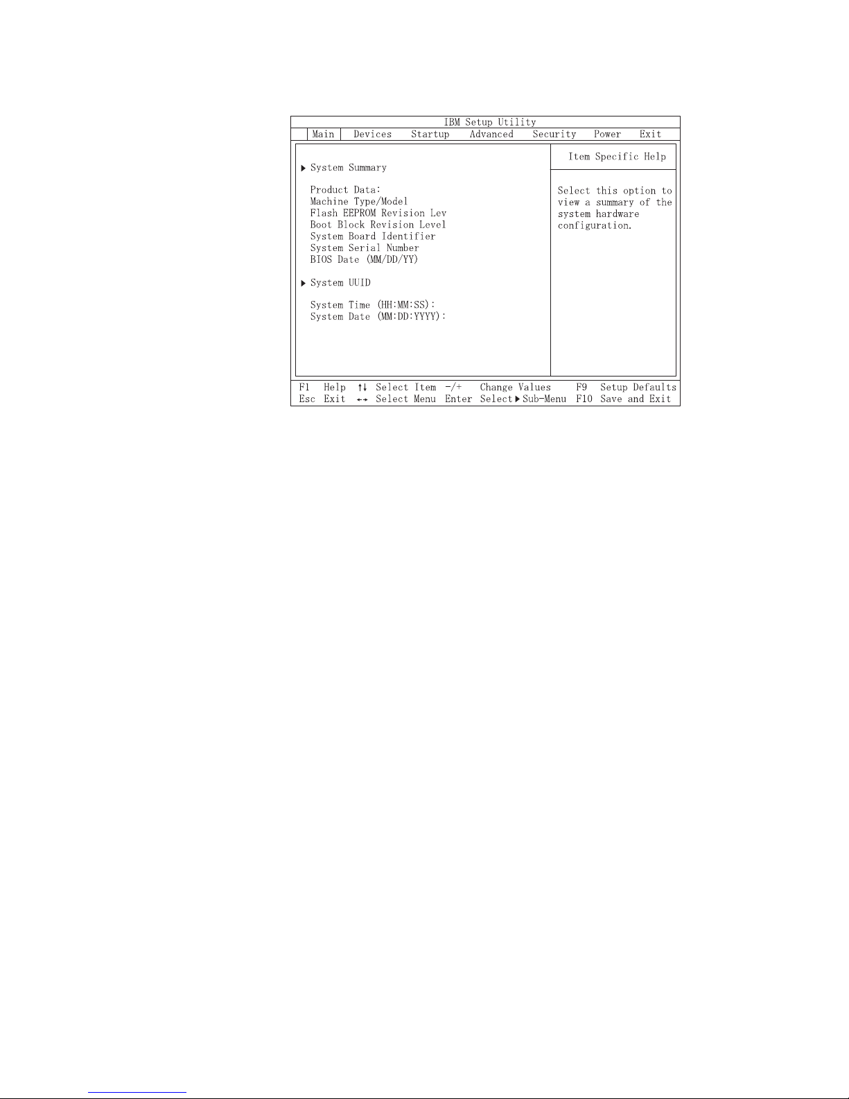
of the first IBM Setup Utility screen is shown here.
6290I01
26KT09AUS
26009A
IBM
1234567
02/22/02
[13:34:25]
[02/22/2002]
The IBM Setup Utility program menu lists items that identify system configuration
topics.
When working with the IBM Setup Utility program menu you must use the
keyboard. The keys used to perform various tasks are displayed at the bottom of
each screen.
When you finish viewing or changing settings press Esc to return to the IBM Setup
Utility program menu (you might have to press Esc several times). If you want to
save the new settings select Save Settings before you exit. Otherwise your changes
will not be saved.
10 Hardware Maintenance Manual

Product Recovery Program menu
Type 6290 machines have recovery and diagnostics programs on a separate hard
drive partition. The Enhanced Diagnostics diskette is not shipped with the
machine. To download the Diagnostics program see “Diagnostics program
download” on page 12.
At startup the machine displays the following prompt:
To start the Product Recovery Program press F11
Attention: Make sure all data is backed up to avoid loss when the Product
Recovery program is used.
After depressing F11 you are given the following options.
v Factory Contents
This utility reformats the hard drive and restores all original files.
v System utilities
1. Repair (Windows NT 4.0 and 2000 Only)
This runs the Windows NT 4.0 emergency repair utility.
2. Run Diagnostics
Runs the IBM Enhanced Diagnostic Program.
3. Create a Diagnostics Diskette
Creates a bootable diagnostic diskette.
4. System Information
Displays information about your computer configuration and allows the user
to gather system information that would be needed during a Help Center
call.
5. Create Recovery/Repair Diskette (Disk to Disk Solution Only)
Creates a startable diskette to restore access to the IBM Product Recovery
program on the hard disk.
6. Recovery CD
In the event of a Hard Disk Drive failure a Recovery CD can be used to
restore the Hard Disk Drive to the original factory preset. Be sure to use the
Recovery CD FRU list to obtain the proper recovery CD for the computer
model you are servicing.
Chapter 4. Diagnostics 11

Diagnostics
Diagnostics program download
Navigating through the diagnostics programs
The Diagnostics program uses a full range of diagnostic utilities to determine the
operating condition of the computer’s hardware components.
For a complete list of error codes and messages see ″Symptom-to-FRU Index″ on
page 39.
To download the Diagnostics program do the following:
v Go to http://www.ibm.com/.
v Select Support.
v Select Personal computing from the ″Get product support for″ pull-down menu.
v Search for the machine type in the ″Quick Path″ box on the left.
v Select Downloadable files from the options on the left.
v Select Diagnostics from the pull down menu.
Use the cursor movement keys to navigate within the menus.
v The Enter key is used to select a menu item.
v The Esc key is used to back up to the previous menu.
v For online help select F1.
Running diagnostics tests
There are four ways to run the diagnostic tests.
1. Using the cursor movement keys highlight Run Normal Test or Run Quick
Test from the Diagnostics menu and then press Enter.
This will automatically run a pre-defined group of tests from each test category.
Run Normal Test runs a more extensive set of tests than does Run Quick Test
and takes longer to execute.
2. Press F5 to automatically run all selected tests in all categories. See ″Test
Selection″.
3. From within a test category press Ctrl-Enter to automatically run only the
selected tests in that category. See ″Test Selection″.
4. Using the cursor movement keys highlight a single test within a test category
then press Enter. This will run only that test.
Press Esc at any time to stop the testing process.
Test results (N/A PASSED FAILED ABORTED) are displayed in the field beside the
test description and in the test log. See “Viewing the test log” on page 16.
Test selection
To select one or more tests use the following procedure.
1. Open the corresponding test category.
2. Using the cursor movement keys highlight the desired test.
3. Press the space bar.
A selected test is marked by >>. Pressing the space bar again de-selects a test
and removes the chevron.
12 Hardware Maintenance Manual

4. Repeat steps 2 and 3 above to select all desired tests.
Test results
Diagnostics test results will produce the following error code format:
Function
Code
v Function Code:
Represents the feature or function within the PC.
v Failure Type:
Represents the type of error encountered.
v DeviceID:
Contains the component’s unit-ID which corresponds to either a fixed disk drive
removable media drive serial or parallel port processor specific RIMM or a
device on the PCI bus.
v Date:
Contains the date on which the diagnostic test was run. The date is retrieved
from CMOS and displayed using the YYYYMMDD format.
v ChkDigits:
Contains a 2-digit check-digit value to ensure the following:
– Diagnostics were run on the specified date.
– Diagnostics were run on the specified IBM computer.
– The diagnostic error code is recorded correctly.
v Text:
Description of the error.
Failure Type DeviceID Date ChkDigits Text
Note: See “Diagnostic error codes” on page 41 for error code listings.
Fixed disk advanced test (FDAT)
PC-Doctor’s (PCDR) Fixed-Disk Advanced Test module (FDAT) is a full-featured
highly configurable fixed-disk test suite. The configurable capabilities of FDAT
allow users to enable or disable specific tests enable or disable testing features
control the test log detail alter testing parameters etc. FDAT will test for and report
most commonly found errors on a fixed-disk drive and is able to test up to 128
SCSI and 4 IDE drives (up to 132 total drives). Drive information is gathered
through FDAT’s enumeration of available devices and user specific configuration
parameters located in the FDAT.INI. FDAT uses information supplied by these
features to indicate specifically what devices are available for test what tests are
available for the device device properties etc. Modify the FDAT.INI file in PC
Doctor for DOS to change testing parameters
FDAT consists of the following subtests and features.
Fixed-Disk Tests:
v Seek Tests: - checks the physical operation of the drive head.
– Linear Seek
– Random Seek
– Min-Max Seek
– Butterfly Seek
Chapter 4. Diagnostics 13

v Verify Tests: - checks the integrity of the data present on the media.
– Linear Verify
– Random Verify
v Surface Scan Tests: - checks the drive media for defects.
– Surface Scan (Linear)
– Surface Scan (Aggressive) - this is disabled for normal customer use.
– Surface Scan (Random)
v SMART: - checks the SMART functionality for drives that support SMART.
– Start SMART Self-Test
– Get SMART test results
Other Test Features:
v Write-Splice Repair - detects and corrects Error Correction Code errors during
Verify tests.
v Auto Spin Down - a gradual spin down of the drive platters to avoid damaging
the media.
v Manufacturer Log - an in-depth manufacturer supported log of errors on the
drive.
Multitasking:
To allow simultaneous testing of multiple hard drives whenever possible the FDAT
module is written as a set of multitasking functions. Each drive under test can run
the same test or run a different test at the same time. Each subtest is written to
handle a single test pass and all test variables are kept track of in a structure
unique for each drive . However when testing IDE drives FDAT will not perform
simultaneous testing of IDE drives that are attached to the same IDE cable. For
example if FDAT is testing four IDE drives on a PC it will perform simultaneous
testing on drives 1 and 3 first (master drives) then perform tests on 2 and 4 (slave
drives). FDAT will also perform simultaneous testing on a master and slave that
are on separate IDE cables but will not perform simultaneous tests on a master and
slave on the same IDE cable. This generally increases the amount of time needed to
test multiple IDE drives. Another limitation of FDAT’S multitasking capability is
the use of Ultra DMA (UDMA). Only one drive at a time can access the UDMA
channel and the UDMA channel buffer must be kept high in order to maintain a
speed advantage over other data transfer modes. In order to use the UDMA
channel during testing users must disable the multitasking feature.
Destructive vs non-destructive testing:
Most of the tests found in FDAT are non-destructive. This means that PCDR will
preserve any data that is present on the tested media prior to beginning any
destructive operations (i.e. write operations). However users can run certain tests
in destructive mode (i.e. surface scan tests). Destructive tests will speed up testing
because FDAT does not preserve the data on the media prior to the test beginning.
Unlike non-destructive tests any data present on the media prior to the test
beginning is lost. FDAT allows for enabling or disabling destructive tests as well as
specifying a range of destructive and non-destructive sectors on the tested drive.
This is done through the configuration of the FDAT.INI .If destructive and
non-destructive ranges somehow overlap then the overlapped area is considered
non-destructive. For example if users specify both destructive and non-destructive
ranges as the same then the entire drive is tested as non-destructive.
14 Hardware Maintenance Manual

Quick and Full erase - hard drive
The Diagnostics program offers two hard drive format utilities:
v Quick Erase Hard Drive
v Full Erase Hard Drive
The Quick Erase Hard Drive provides a DOS utility that performs the following
steps.
v Destroys the Master Boot Record (MBR) on the hard drive.
v Destroys all copies of the FAT Table on all partitions (both the master and
backup).
v Destroys the partition table.
v Provides messages that warn the user that this is a non-recoverable process.
Chapter 4. Diagnostics 15

The Full Erase Hard Drive provides a DOS utility that performs the following
steps.
v Performs all the steps in Quick Erase.
v Provides a DOS utility that writes random data to all sectors of the hard drive.
v Provide an estimate of time to completion along with a visual representation of
completion status.
v Provides messages that warn the user about non-recoverable process.
Important: Make sure that all data is backed up before using the Quick or Full Erase
functions.
To select the Quick Erase or Full Erase Hard Drive utility use the following
procedure.
1. Select the UTILITY option on the toolbar and press Enter.
2. Select either the QUICK ERASE or FULL ERASE HARD DISK option and
follow the instructions.
Viewing the test log
Errors reported by the diagnostic test will be displayed by the program as a failed
test.
To view details of a failure or to view a list of test results use the following
procedure from any test category screen.
v Press F3 to activate the log file.
v Press F3 again to save the file to diskette or F2 to print the file.
16 Hardware Maintenance Manual

Chapter 5. Installing Options
This section contains information on adding or replacing customer options.
Installing external options
This section shows the various external connectors on your computer to which you
can attach external options such as external speakers a printer or a scanner. For
some external options you must install additional software in addition to making
the physical connection. When adding an external option use the information in
this section to identify the required connector and then use the instructions that
come with the option to help you make the connection and install any software or
device drivers that are required for the option.
© Copyright IBM Corp. 2001 17
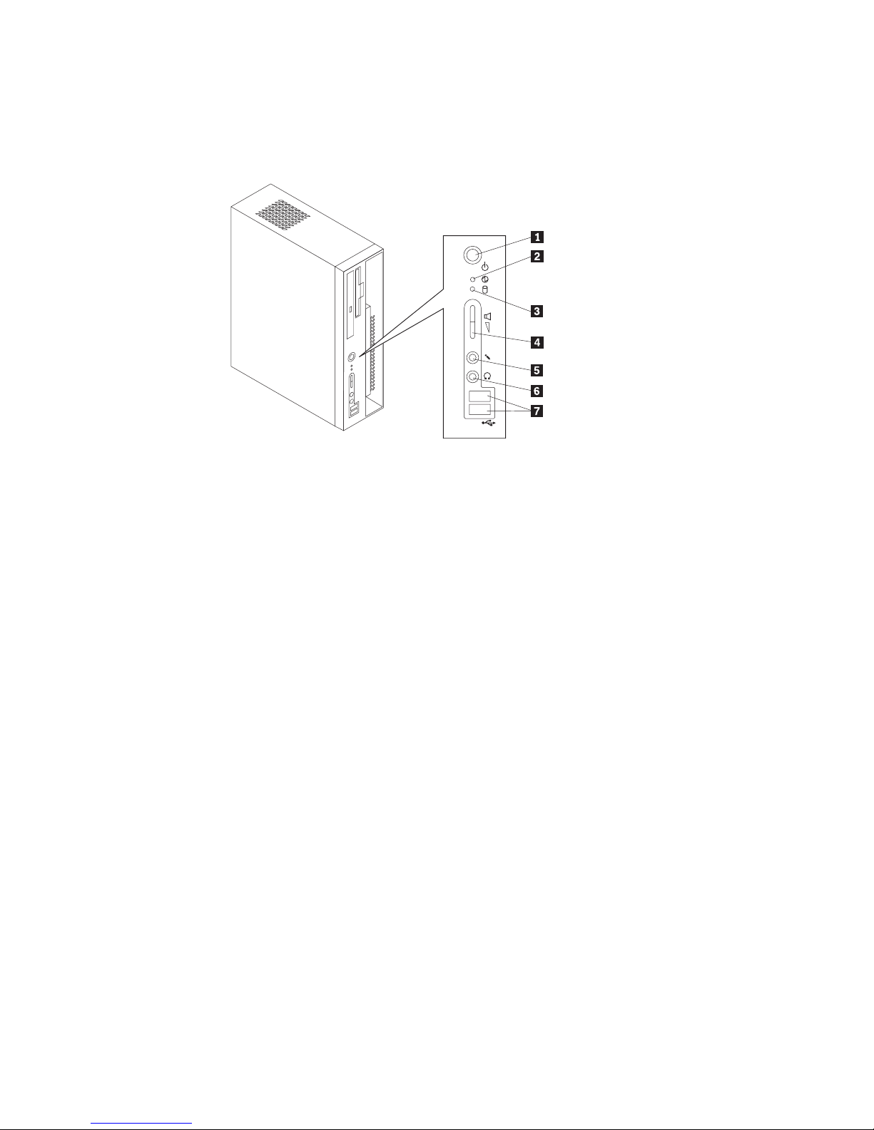
Locating controls and connectors on the front of your
computer
The following illustration shows locations of the controls and connectors on the
front of your computer.
1 Power button 5 Headphone connector
2 Power-on indicator 6 Microphone connector
3 Hard disk drive activity indicator 7 USB connectors
4 Speaker volume control
18 Hardware Maintenance Manual
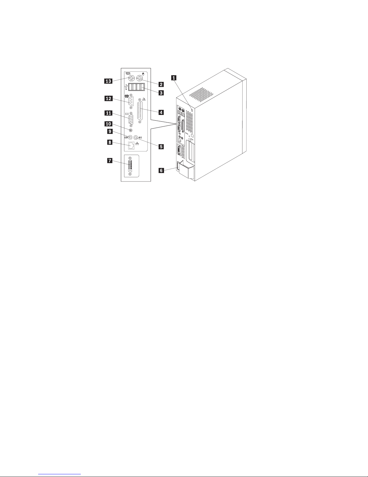
Locating connectors on the rear of your computer
The following illustration shows locations of connectors on the rear of your
computer.
1 Cable-lock latch 8 Ethernet connector
2 PS/2 Mouse connector 9 Audio line-out connector
3 USB connectors (4) 10 Digital monitor 12 V connector
4 Parallel connector 11 VGA monitor connector
5 Audio line-in connector 12 Serial connector
6 Power cord connector 13 PS/2 Keyboard connector
7 Digital monitor connector
Note: Some connectors on the rear of your computer are color-coded to help
determine where to connect the cables.
Obtaining device drivers
You can obtain device drivers for operating systems that are not preinstalled at
http://www.ibm.com/pc/support/ on the World Wide Web. Installation
instructions are provided in README files with the device-driver files.
Chapter 5. Installing Options 19
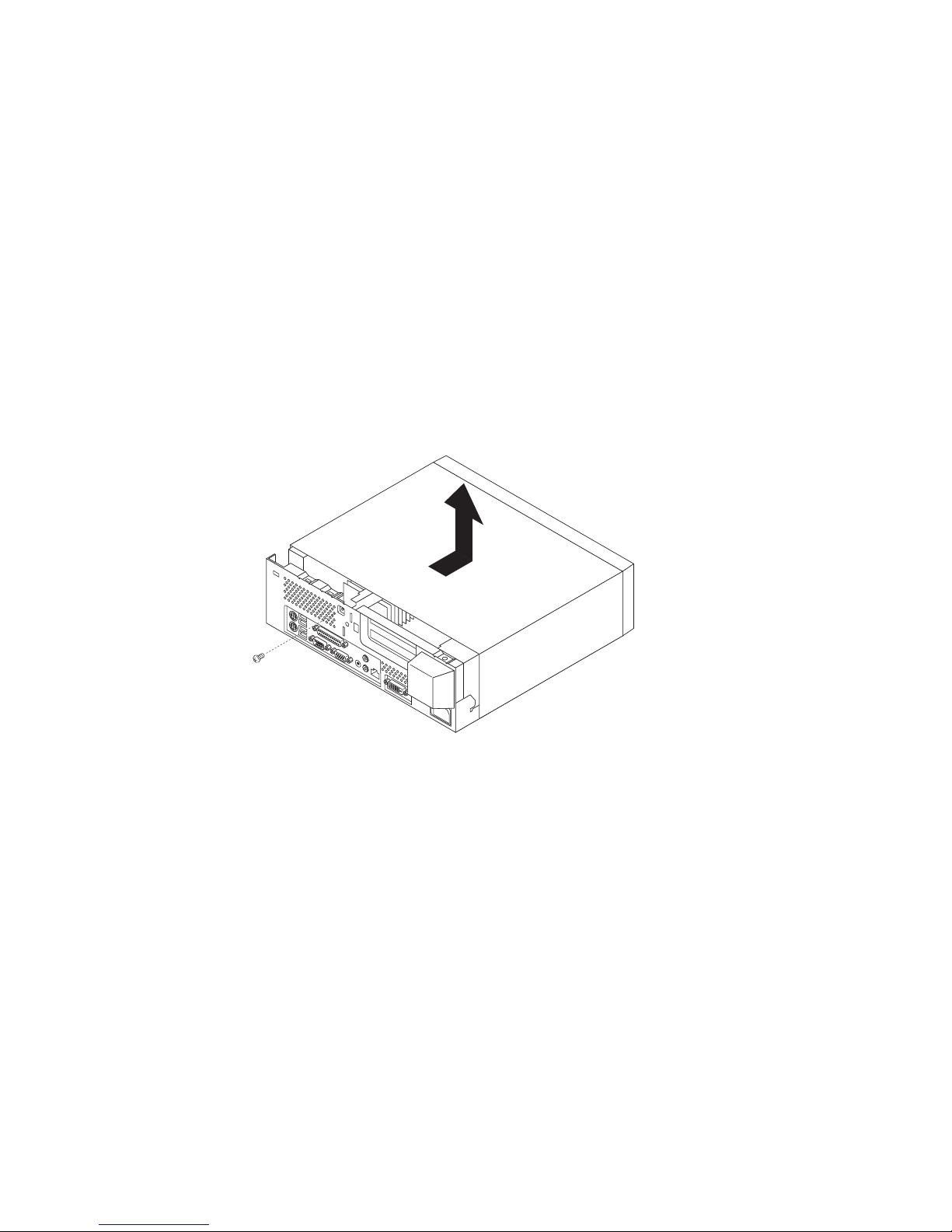
Removing the cover
Important:
See “Safety information” on page 93 and “Handling electrostatic
discharge-sensitive devices” on page 96 before you begin.
To remove the cover:
1. Shut down your operating system remove any media (diskettes CDs or tapes)
from the drives and turn off all attached devices and the computer.
2. Unplug all power cords from electrical outlets.
3. Disconnect all cables attached to the computer. This includes power cords
input/output (I/O) cables and any other cables that are connected to the
computer.
4. Remove the floor stand if attached.
5. Remove the screw that secures the cover at the rear of the system unit.
6. Carefully slide the cover forward and lift it up to remove.
20 Hardware Maintenance Manual
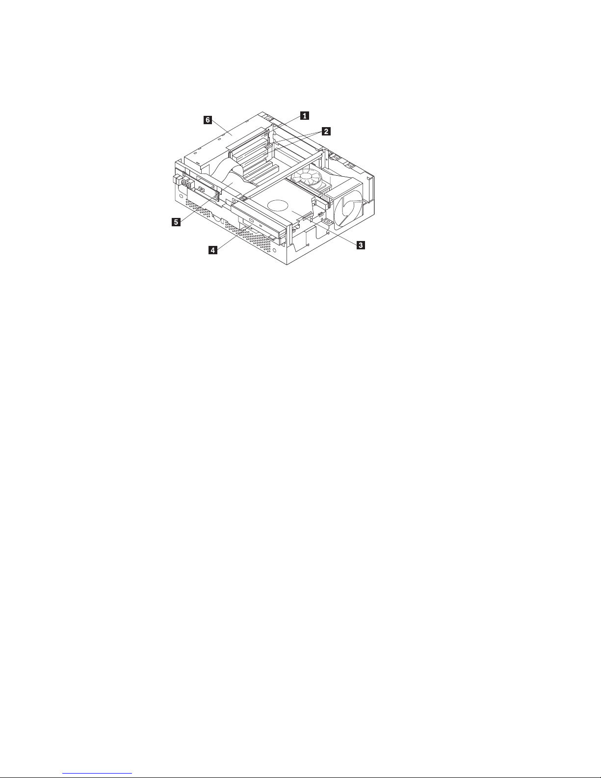
Locating components
The following illustration will help you locate the various components in your
computer.
1 PCI riser 4 Diskette drive
2 PCI slots (2) 5 Hard disk drive
3 CD drive 6 Power supply
Accessing system board components
Use this procedure to gain access to components on the system board such as
memory DIMMs the battery and the Clear CMOS/BIOS recovery jumper. You can
also use this procedure to learn how to remove drives when updating to different
or higher capacity drives.
To access system board components:
1. Turn off the computer and all attached devices.
2. Unplug the power cord and remove the cover. See “Removing the cover” on
page 20.
Chapter 5. Installing Options 21
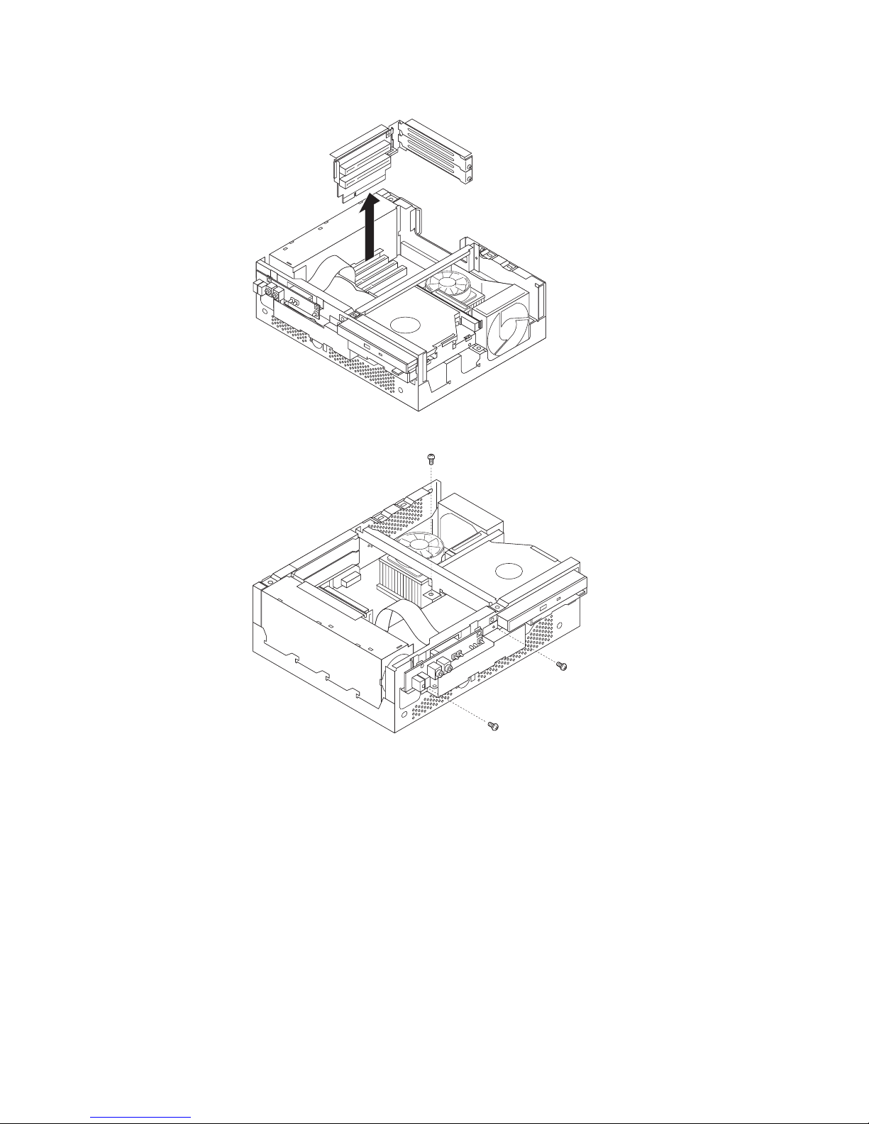
3. Remove the PCI riser. Do not remove any installed adapters from the riser.
4. Remove the three screws holding the hard disk drive tray.
22 Hardware Maintenance Manual
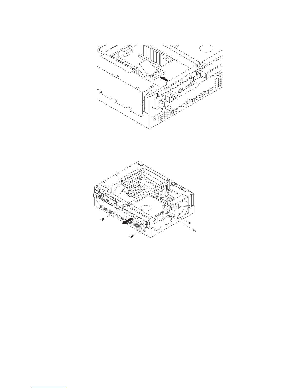
5. Unplug the flat cable attached to the small circuit board at the front.
6. Remove the two screws holding the CD and diskette drive tray.
Note: The individual drives are removed with one screw each accessible from
the side.
Chapter 5. Installing Options 23
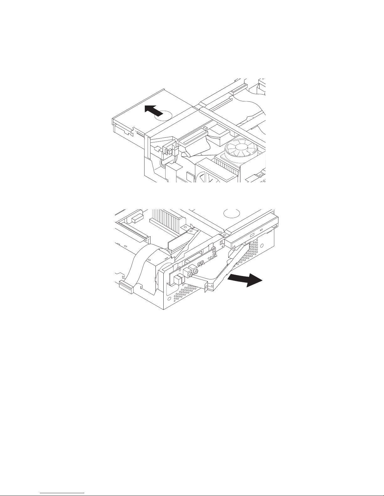
7. Due to cable length limitations both drive trays must slide outward together.
Slide both drive trays out far enough to access the system board. This might
require disconnecting cables that are connected to the drives and to the system
board. Note where the cables are connected before disconnecting them.
24 Hardware Maintenance Manual
 Loading...