

Lenovo 46M4002, 46M4003, 46M4004, 46M4005 Installation And Maintenance Manual

1U C19 and C13 Switched and Monitored
PDUs
Installation and Maintenance Guide

Note: Before using this information and the product it supports, read the general information in Appendix D
“Notices” on page 67; the safety information, warranties, and licenses information on the Lenovo Web site at:
https://support.lenovo.com/documents/LNVO-DOCS
Second Edition (October 2018)
© Copyright Lenovo 2015, 2018.
LIMITED AND RESTRICTED RIGHTS NOTICE: If data or software is delivered pursuant to a General Services
Administration “GSA” contract, use, reproduction, or disclosure is subject to restrictions set forth in Contract No. GS35F-05925.

Contents
Safety . . . . . . . . . . . . . . . . . . . iii
Chapter 1. Introduction . . . . . . . . . 1
Notices and statements in this document . . . . . . 1
Installation requirements . . . . . . . . . . . . 2
Inventory checklist. . . . . . . . . . . . . . . 2
Parts that come with all PDU models. . . . . . 2
Parts that come with the 1U PDU models . . . . 3
Features of the PDU . . . . . . . . . . . . . . 4
Hardware components . . . . . . . . . . . . . 5
Front view . . . . . . . . . . . . . . . . 5
Rear view . . . . . . . . . . . . . . . . 6
PDU load groups . . . . . . . . . . . . . . . 7
Load balancing . . . . . . . . . . . . . . . . 7
Chapter 2. Installing the 1U PDU
vertically in a rack cabinet . . . . . . . . 9
Installing the PDU in the side of a rack cabinet . . . 9
Installing the PDU in the side of an Enterprise rack
cabinet only . . . . . . . . . . . . . . . . 12
Chapter 3. Installing the 1U PDU
horizontally in a rack cabinet . . . . . 17
Connecting the PDU environment sensor to the
PDU . . . . . . . . . . . . . . . . . . . 49
Chapter 7. Customer replaceable
unit parts . . . . . . . . . . . . . . . . 53
Chapter 8. PDU specifications . . . . 55
Appendix A. Default PDU settings . . 59
Appendix B. Behavior of the PDU
reset button . . . . . . . . . . . . . . 61
Appendix C. Getting help and
technical assistance . . . . . . . . . . 63
Before you call . . . . . . . . . . . . . . . 63
Using the documentation . . . . . . . . . . . 64
Getting help and information from the World Wide
Web . . . . . . . . . . . . . . . . . . . 64
How to send DSA data . . . . . . . . . . . . 64
Creating a personalized support web page . . . . 64
Software service and support . . . . . . . . . 65
Hardware service and support . . . . . . . . . 65
Taiwan product service . . . . . . . . . . . . 65
Chapter 4. Cabling the PDU . . . . . . 23
Connecting to a console . . . . . . . . . . . 23
Connecting to a LAN . . . . . . . . . . . . . 24
Connecting to a PDU environment sensor . . . . 24
Connecting output devices . . . . . . . . . . 25
Chapter 5. Monitoring the power
status . . . . . . . . . . . . . . . . . 27
Using the PDU Configuration Utility to set up the
PDU . . . . . . . . . . . . . . . . . . . 27
Power-on sequencing (some models) . . . . . . 31
Using HyperTerminal through the serial port . . 33
Using Telnet through the Ethernet port . . . . 35
Using SNMP through the Ethernet port . . . . 38
Using the web interface . . . . . . . . . . . . 39
Starting the web interface . . . . . . . . . 40
Power management relay setting . . . . . . 41
Environment status and configuration . . . . 41
Modifying the basic settings . . . . . . . . 42
Changing the network configuration . . . . . 46
Event and history log summaries . . . . . . 46
Chapter 6. Using the PDU
environment sensor . . . . . . . . . . 49
Features. . . . . . . . . . . . . . . . . . 49
Appendix D. Notices. . . . . . . . . . 67
Trademarks . . . . . . . . . . . . . . . . 68
Important notes. . . . . . . . . . . . . . . 68
Recycling information . . . . . . . . . . . . 68
Particulate contamination . . . . . . . . . . . 69
Telecommunication regulatory statement. . . . . 69
Electronic emission notices . . . . . . . . . . 69
Federal Communications Commission (FCC)
statement . . . . . . . . . . . . . . . 70
Industry Canada Class A emission compliance
statement . . . . . . . . . . . . . . . 70
Avis de conformité à la réglementation
d'Industrie Canada. . . . . . . . . . . . 70
Australia and New Zealand Class A
statement . . . . . . . . . . . . . . . 70
European Union EMC Directive conformance
statement . . . . . . . . . . . . . . . 70
Germany Class A statement . . . . . . . . 70
Japanese electromagnetic compatibility
statements . . . . . . . . . . . . . . . 71
Korea Communications Commission (KCC)
statement . . . . . . . . . . . . . . . 72
Russia Electromagnetic Interference (EMI)
Class A statement . . . . . . . . . . . . 72
People's Republic of China Class A electronic
emission statement . . . . . . . . . . . 73
© Copyright Lenovo 2015, 2018 i

Taiwan Class A compliance statement . . . . 73
Taiwan BSMI RoHS declaration . . . . . . . 74
Index . . . . . . . . . . . . . . . . . . 75
ii 1U C19 and C13 Switched and Monitored PDUs Installation and Maintenance Guide
Safety
Before installing this product, read the Safety Information.
Antes de instalar este produto, leia as Informações de Segurança.
Læs sikkerhedsforskrifterne, før du installerer dette produkt.
Lees voordat u dit product installeert eerst de veiligheidsvoorschriften.
Ennen kuin asennat tämän tuotteen, lue turvaohjeet kohdasta Safety Information.
Avant d'installer ce produit, lisez les consignes de sécurité.
Vor der Installation dieses Produkts die Sicherheitshinweise lesen.
Prima di installare questo prodotto, leggere le Informazioni sulla Sicurezza.
Les sikkerhetsinformasjonen (Safety Information) før du installerer dette produktet.
Antes de instalar este produto, leia as Informações sobre Segurança.
Antes de instalar este producto, lea la información de seguridad.
Läs säkerhetsinformationen innan du installerar den här produkten.
Each caution and danger statement in this documentation is labeled with a number. This number is used to
cross reference an English-language caution or danger statement with translated versions of the caution or
danger statement in the Safety Information document.
For example, if a caution statement is labeled Statement 1, translations for that caution statement are in the
Safety Information document under Statement 1.
Be sure to read all caution and danger statements in this documentation before you perform the procedures.
Read any additional safety information that comes with your system or optional device before you install the
device.
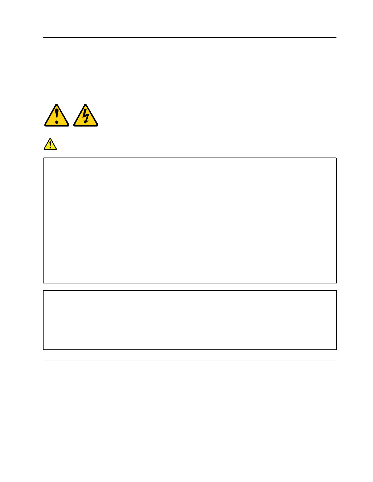
Statement 1
DANGER
Electrical current from power, telephone, and communication cables is hazardous.
To avoid a shock hazard:
• Do not connect or disconnect any cables or perform installation, maintenance, or reconfiguration
of this product during an electrical storm.
• Connect all power cords to a properly wired and grounded electrical outlet.
• Connect to properly wired outlets any equipment that will be attached to this product.
• When possible, use one hand only to connect or disconnect signal cables.
• Never turn on any equipment when there is evidence of fire, water, or structural damage.
• Disconnect the attached power cords, telecommunications systems, networks, and modems
before you open the device covers, unless instructed otherwise in the installation and
configuration procedures.
• Connect and disconnect cables as described in the following table when installing, moving, or
opening covers on this product or attached devices.
Table for Safety Statement 1 that explains the steps to connect and disconnect cables.
To Connect: To Disconnect:
1. Turn everything OFF.
2. First, attach all cables to devices.
3. Attach signal cables to connectors.
4. Attach power cords to outlet.
5. Turn device ON.
1. Turn everything OFF.
2. First, remove power cords from outlet.
3. Remove signal cables from connectors.
4. Remove all cables from devices.
Statement 13
DANGER
Overloading a branch circuit is potentially a fire hazard and a shock hazard under certain
conditions. To avoid these hazards, ensure that your system electrical requirements do not exceed
branch circuit protection requirements. Refer to the information that is provided with your device
for electrical specifications.

Statement 14
CAUTION:
Hazardous voltage, current, and energy levels might be present. Only a qualified service technician is
authorized to remove the covers where the following label is attached.

Chapter 1. Introduction
The switched and monitored 1U PDU products enable you to connect up to nine C19 devices or up to 12
C13 devices (depending on the PDU model) and an additional three C13 peripheral devices to a single
dedicated power source. The PDUs have power monitoring capabilities.
The following PDU models are available:
• 46M4002 - 1U 9 C19 / 3 C13 Switched and Monitored DPI PDU (with removable power cord)
• 46M4003 - 1U 9 C19 / 3 C13 Switched and Monitored 60 A 3 Phase PDU (with attached power cord)
• 46M4004 - 1U 12 C13 Switched and Monitored DPI PDU (with removable power cord)
• 46M4005 - 1U 12 C13 Switched and Monitored 60 A 3 Phase PDU (with attached power cord)
The IBM Systems Director Active Energy Manager product can monitor and control the PDUs. Active Energy
Manager is an IBM Systems Director plug-in that measures and reports server power consumption as it
occurs. Active Energy Manager includes a feature to associate IBM Systems Director managed resources
with the power outlets on the PDUs. This enables you to know how much power each server is consuming
and which servers will be affected by any PDU outages. You can use the graphing capability of Active Energy
Manager to show a trending line for power that is being drawn by the outlets of the PDU models, showing
which systems are connected to them.
Active Energy Manager also enables you to show a trending line for the temperature of the PDU and the
temperature that is measured by the environment sensor. In addition to monitoring, Active Energy Manager
can control power of the individual outlets. From a central location, Active Energy Manager can power off or
power on the outlets. This enables an administrator to prevent someone from connecting additional
equipment into unused outlets, thereby making it easier to control power consumption within a rack. Active
Energy Manager can also shut down outlets in an emergency situation.
If firmware and documentation updates are available, you can download them from the Lenovo website. The
PDU might have features that are not described in the documentation that comes with the PDU, and the
documentation might be updated occasionally to include information about those features, or technical
updates might be available to provide additional information that is not included in the PDU documentation.
To check for updates, Go to
http://www.lenovo.com/support.
Notices and statements in this document
The caution and danger statements in this document are also in the multilingual Safety Information
document, which is on the Documentation CD. Each statement is numbered for reference to the
corresponding statement in your language in the Safety Information document.
The following notices and statements are used in this document:
• Note: These notices provide important tips, guidance, or advice.
• Important: These notices provide information or advice that might help you avoid inconvenient or
problem situations.
• Attention: These notices indicate potential damage to programs, devices, or data. An attention notice is
placed just before the instruction or situation in which damage might occur.
• Caution: These statements indicate situations that can be potentially hazardous to you. A caution
statement is placed just before the description of a potentially hazardous procedure step or situation.
© Copyright Lenovo 2015, 2018 1
• Danger: These statements indicate situations that can be potentially lethal or extremely hazardous to you.
A danger statement is placed just before the description of a potentially lethal or extremely hazardous
procedure step or situation.
Installation requirements
You will need the following tools to install the PDU in a rack cabinet:
• One Phillips screwdriver
• One 10 mm (11/32 in.) wrench
• One cage-nut-insertion tool or flat-blade screwdriver (for installing cage nuts in some rack cabinets)
1
You can install a 1U PDU vertically in the side of a rack cabinet or horizontally within 1U
space in a rack cabinet.
• For vertical mounting instructions of the 1U PDU, see Chapter 2 “Installing the 1U PDU vertically in a rack
cabinet” on page 9.
• For horizontal mounting instructions of the 1U PDU, see Chapter 3 “Installing the 1U PDU horizontally in a
rack cabinet” on page 17.
of EIA mounting
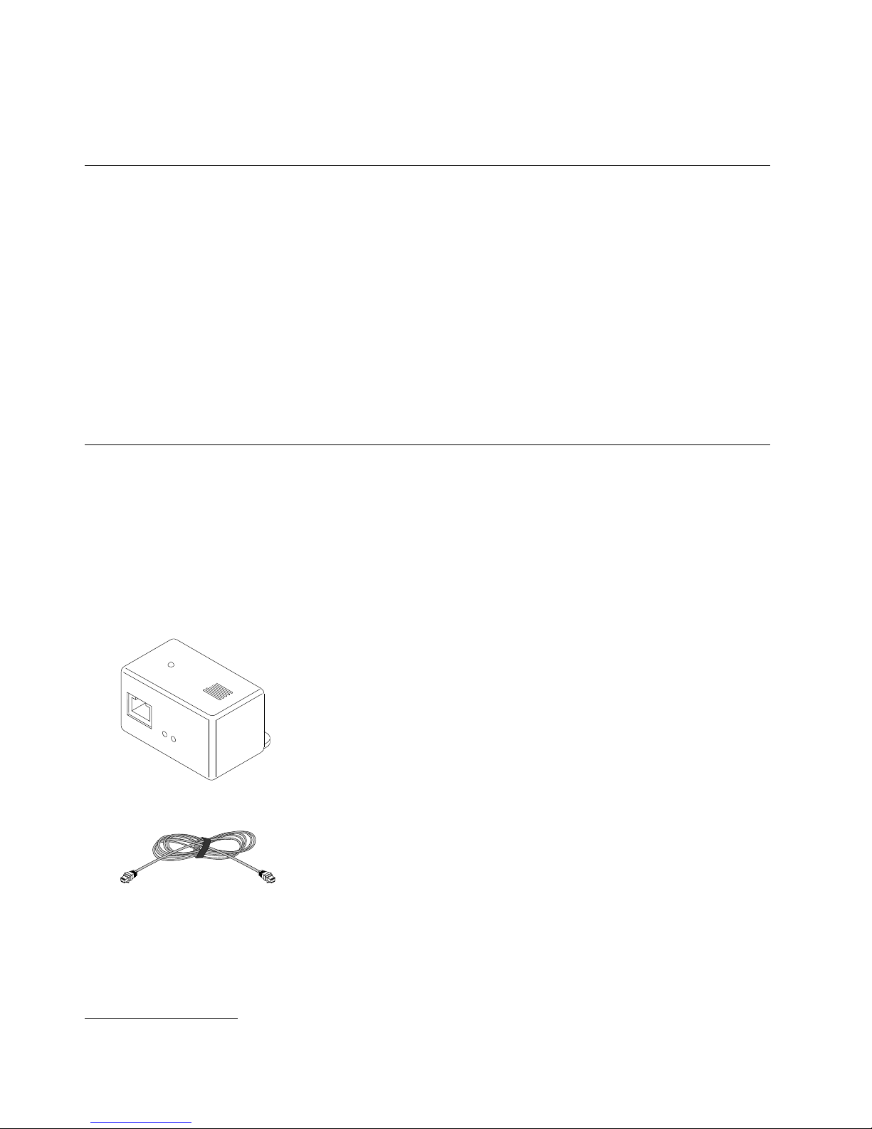
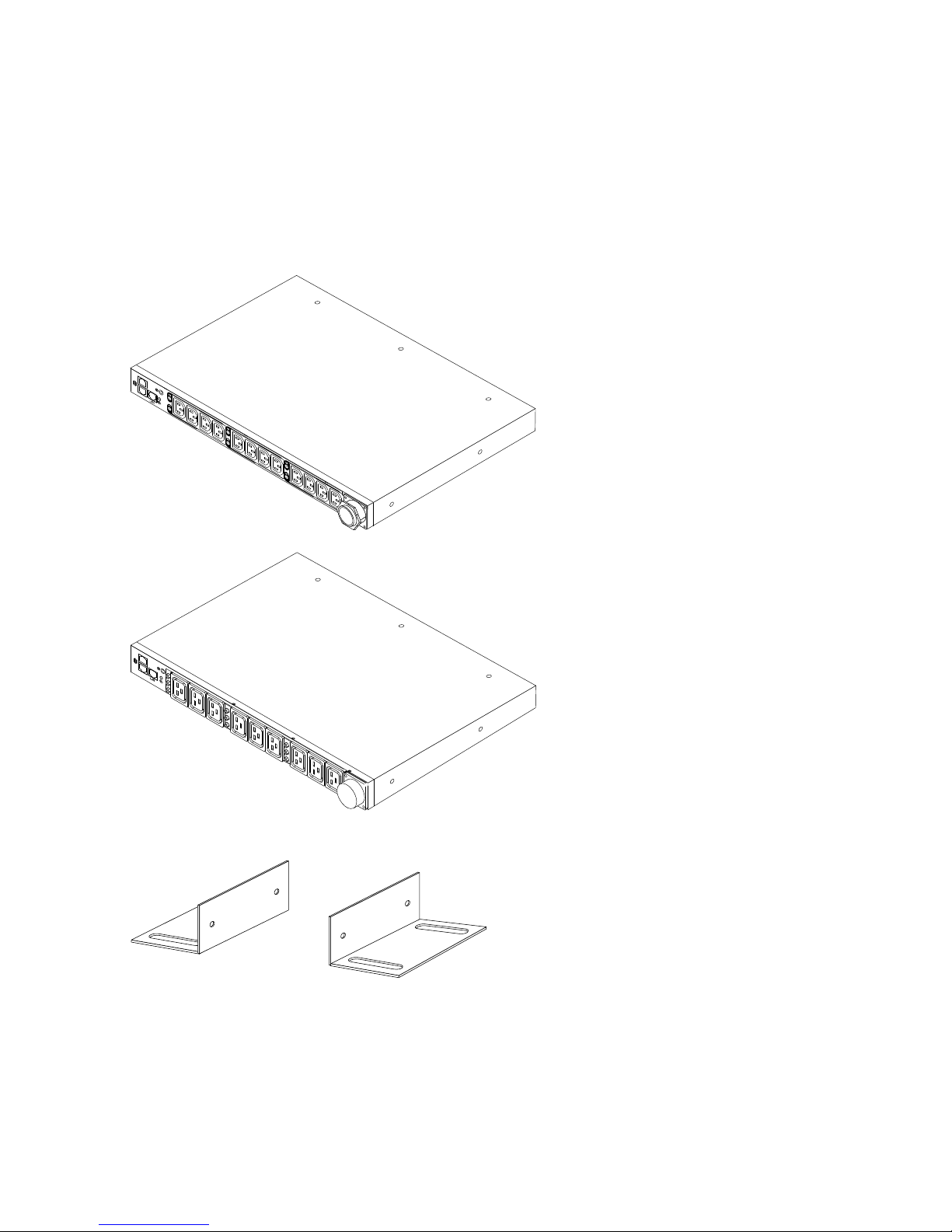
Inventory checklist
Note: The illustrations in this document might differ slightly from your hardware.
Parts that come with all PDU models
The following parts come with all PDU models:
• One PDU environment sensor kit:
– One PDU environment sensor
– One Category 5 Ethernet cable
– One mounting screw
– Self-adhesive hook-and-loop fastener pad
• Miscellaneous hardware kit (for attaching the mounting brackets to the PDU and installing the PDU in a
rack cabinet)
1. One U is equal to 4.45 cm (1.75 in.)
2
1U C19 and C13 Switched and Monitored PDUs Installation and Maintenance Guide
1. Power cables for devices that you will connect to the PDU do not come with the PDU.
2. You will have some unused parts depending on how you install the PDU.
Parts that come with the 1U PDU models
The following parts come with the 1U PDU models:
• One of the following PDU models (some models come with an attached power cord)
• Two vertical-mounting brackets (for all rack cabinets)
• Two short mounting brackets (for horizontal mounting in all rack cabinets; for vertical mounting only in
Enterprise rack cabinets)
Chapter 1. Introduction 3
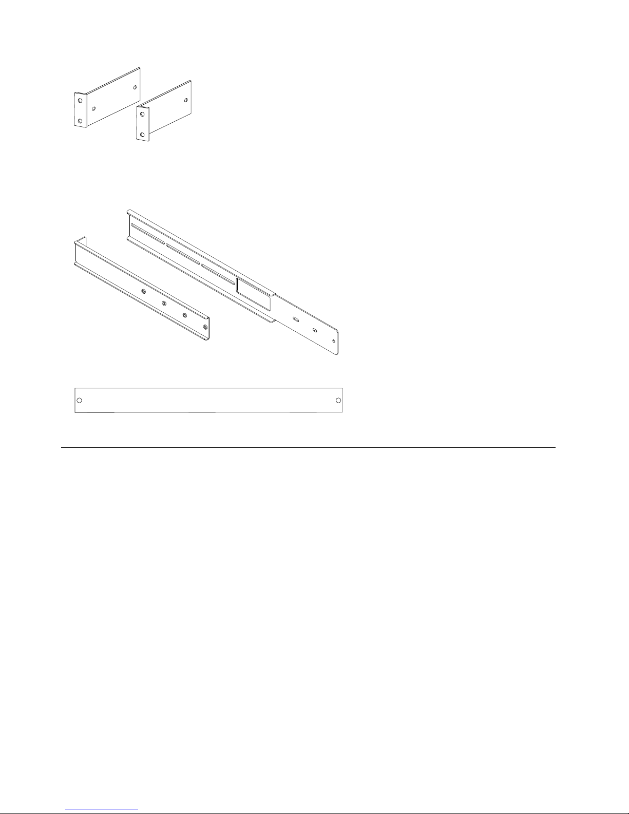
• Two adjustable mounting rails (for horizontal mounting in all rack cabinets)
Note: The following illustration shows the two components of one adjustable mounting rail. The
adjustable mounting rail might come pre-assembled.
• One 1U blank filler panel
• Cable straps
Features of the PDU
The PDU models have the following features:
• Ability to access the versatile sensors in the PDU environment sensor through the environment sensor
inputs
Note: This feature requires the PDU environment sensor, which comes with the PDU.
• Address-specific IP security masks to prevent unauthorized access
• Remote monitoring of connected devices and sensors
• Monitoring of the PDU locally, remotely through IBM Systems Director Active Energy Manager, or
remotely through a console or network
• Comprehensive power management and flexible configuration through a web browser, NMS, Telnet,
SNMP, or HyperTerminal (console)
• Configurable user-security control
• Daily history report through e-mail
• Detailed data logging for statistical analysis and diagnostics
• Easy-to-use interface to display input and output status
• Event notification through SNMP trap or e-mail alerts
• Upgrade utility for easy firmware updates
4
1U C19 and C13 Switched and Monitored PDUs Installation and Maintenance Guide
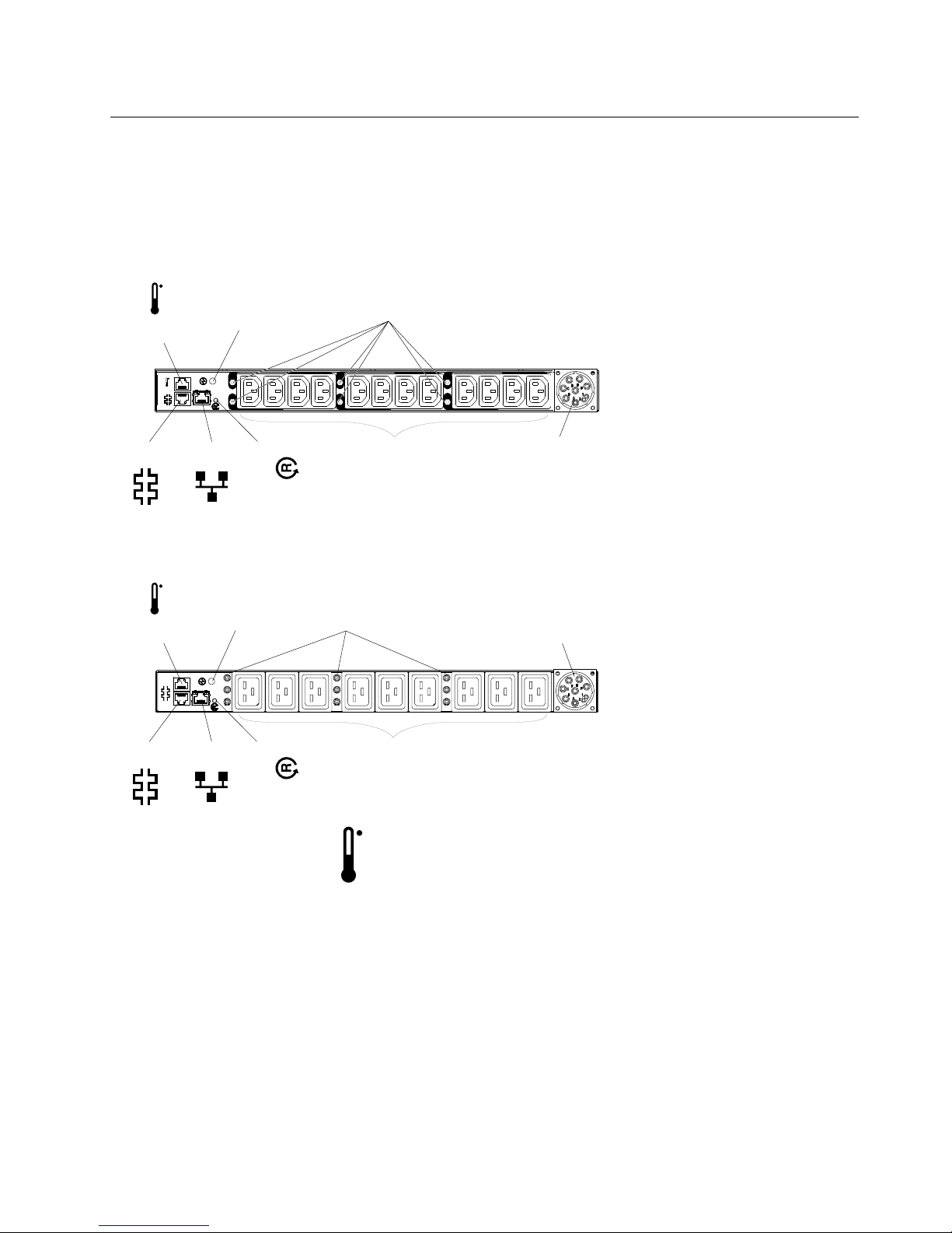
Hardware components
5 6
Input power
connector
Power outlets
21
3 4
Circuit breakers
LED
Reset button
RS-232
connector
LAN
Ethernet
connector
Environment
sensor connector
LED
Input power
connector
Power outlets
Circuit breakers
Reset button
LAN
RS-232
connector
Ethernet
connector
Environment
sensor connector
The following sections provide descriptions of the front and rear components on the PDUs.
Front view
The following illustration shows the components and controls on the front of the 1U PDU with 12 C13 outlets
on the front.
The following illustration shows the components and controls on the front of the 1U PDU with 9 C19 outlets
on the front.
Environment sensor connector
You can connect a PDU environment sensor to this connector. The PDU environment sensor monitors
humidity and temperature. The connection of a PDU environment sensor is automatically detected.
LED
The green LED shows the PDU input voltage status. When this LED is lit, the PDU is receiving voltage. If
the input voltage is too low, this LED is flashing.
Circuit breakers
If the load current rating for a power outlet exceeds 20 A, the associated circuit breaker is activated (the
breaker pole pops out), and power to the outlet is turned off automatically. To reset the circuit breaker,
firmly press the breaker pole until it locks into place.
Note: To manually disconnect power to a device that is connected to the PDU, disconnect the device
power cord from the PDU power outlet.
Chapter 1. Introduction 5
Input power connector
Connect a power cord to this connector.
Note: Some PDU models come with an attached power cord.
Power outlets
You can connect a device to each power outlet. Depending on the PDU model, there are C19 power
outlets and C13 power outlets.
Reset button
Use this button to reset the PDU for communication purposes only. Resetting the PDU does not affect
the loads.
Ethernet connector
Use this connector to configure the PDU through a LAN. The Ethernet connector supports 10/100 auto
sense network connection.
Green LED (on the left):
• This LED is lit when the PDU is connected to a 100 Mb network.
• This LED flashes while data is transmitted and received.
Amber LED (on the right):
• This LED is lit when the PDU is connected to a 10 Mb network.
• This LED flickers while data is transmitted and received.
RS-232 connector
Connect a DB9-to-RJ-45 cable to this connector and to the serial (COM) connector on a workstation or
notebook computer, and use the workstation or notebook computer as a configuration console.
Green LED (on the left in a horizontal orientation; on the top in a vertical orientation):
• This LED is lit when the power to the PDU is turned on.
• This LED flashes (500 ms on, 500 ms off) while the PDU is starting to indicate startup status.
Amber LED (on the right in a horizontal orientation; on the bottom in a vertical orientation):
• This LED flashes while the PDU is communicating with a server or computer or when it is reading data
from a PDU environment sensor.
Rear view
The following illustration shows the power outlets on the rear of the 1U 9 C19 / 3 C13 switched and
monitored PDU models. There are no power outlets on the rear of the 1U PDU with 12 C13 outlets on the
front.
6 1U C19 and C13 Switched and Monitored PDUs Installation and Maintenance Guide
PDU load groups
The PDU load groups are described in the following tables.
Table 1. Switched and monitored 1U C19 PDU load groups
Circuit breaker number Associated front outlet Associated rear outlet
1 1 10 1
2 2
3 3
4 4 11 2
5 5
6 6
7 7 12 3
8 8
9 9
Table 2. Switched and monitored 1U C13 PDU load groups
Associated outlets (The load
segment number that is visible on
Circuit breaker number
1
the front of the PDU is in
parentheses.)
1 and 2 (1)
Phase (when using 3-phase input
power)
1
Phase (when using 3phase input power)
2
3
4
5
6
3 and 4 (2)
5 and 6 (3)
7 and 8 (4)
9 and 10 (5)
11 and 12 (6)
2
3
Load balancing
The internal circuits of some PDUs might be overloaded if you are not aware of the circuit breaker
specifications and how the PDU outlets are connected. If loads are greater than the specification of the
circuit breaker, it will trip and turn off the load.
There are either six or nine circuit breakers on the front of the PDU, depending on the model. Each circuit
breaker is rated for 20 amps. When you connect loads, make sure that the rating for each circuit breaker is
not exceeded.
Some PDUs can be connected to three-phase power. The loads should be distributed across all three
phases. If single-phase power is used, it also is important to distribute the load between the outlet groups.
The PDU models with 12 C13 outlets on the front have phase one connected to the first 4 outlets, outlet
group one. Phase two is connected to the next 4 outlets, outlet group two and phase three are connected to
the last 4 outlets, outlet group three (see the following illustration).
Chapter 1. Introduction 7
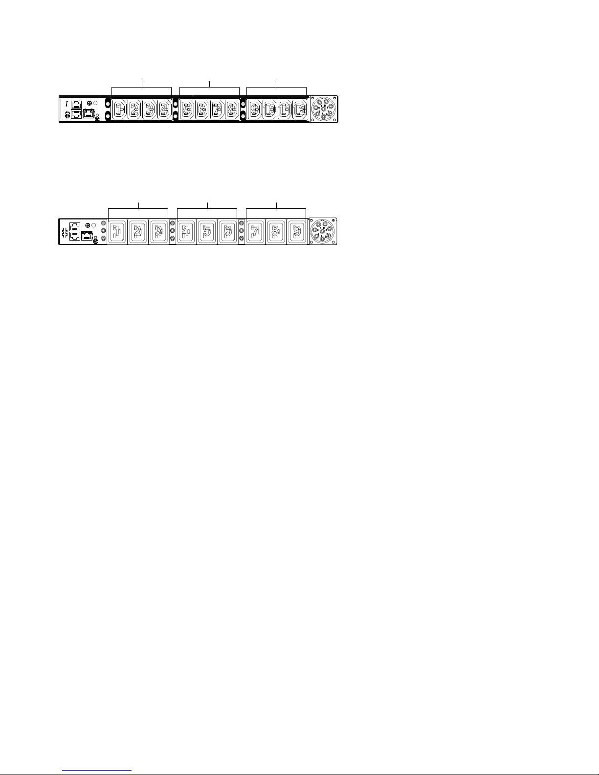
5 6
21
3 4
LAN
21 3 4 65 7 8 109 1112
Phase 1
outlet group 1
Phase 2
outlet group 2
Phase 3
outlet group 3
The PDU models with 9 C19 outlets on the front have phase one connected to the first three (3) outlets, outlet
LAN
21 3 4 65 7 8 9
Phase 1
outlet group 1
Phase 2
outlet group 2
Phase 3
outlet group 3
group one. Phase 2 is connected to the next three (3) outlets, outlet group two. Phase 3 is connected to the
last 3 outlets, outlet group three (see the following illustration).
Some models have 3 outlets on the rear of the PDU. These outlets are not monitored or switched. Each
outlet is connected to a different phase.
To balance loads on the PDU, do not connect loads so that there is more load on one group of outlets than
others. For example, if there are three loads on a 9-outlet PDU, do not use outlets 1, 2, or 3; use outlets 1, 4,
and 7.
If there are three loads on a 12-outlet PDU, use outlets 1, 5, and 9. If there are more then 3 loads, distribute
them across the three output groups.
8
1U C19 and C13 Switched and Monitored PDUs Installation and Maintenance Guide
Chapter 2. Installing the 1U PDU vertically in a rack cabinet
This chapter describes how to install the PDU vertically in a rack cabinet. To install the PDU in the side of an
Enterprise rack cabinet, see “Installing the PDU in the side of an Enterprise rack cabinet only ” on page 12.
Statement 1
DANGER
Electrical current from power, telephone, and communication cables is hazardous.
To avoid a shock hazard:
• Do not connect or disconnect any cables or perform installation, maintenance, or reconfiguration
of this product during an electrical storm.
• Connect all power cords to a properly wired and grounded electrical outlet.
• Connect to properly wired outlets any equipment that will be attached to this product.
• When possible, use one hand only to connect or disconnect signal cables.
• Never turn on any equipment when there is evidence of fire, water, or structural damage.
• Disconnect the attached power cords, telecommunications systems, networks, and modems
before you open the device covers, unless instructed otherwise in the installation and
configuration procedures.
• Connect and disconnect cables as described in the following table when installing, moving, or
opening covers on this product or attached devices.
To Connect: To Disconnect:
1. Turn everything OFF.
2. First, attach all cables to devices.
3. Attach signal cables to connectors.
4. Attach power cords to outlet.
5. Turn device ON.
1. Turn everything OFF.
2. First, remove power cords from outlet.
3. Remove signal cables from connectors.
4. Remove all cables from devices.
Installing the PDU in the side of a rack cabinet
The mounting holes on the upper and lower side braces in a rack side compartment must be between 48.6
cm (19.1 in.) and 56.9 cm (22.4 in.) apart. If your rack cabinet has movable side braces, see the rack cabinet
documentation for information about relocating the side braces if they are not already spaced for this
installation.
Note: Removing the rack doors and side panels might make installation easier. See the rack cabinet
documentation for more information.
© Copyright Lenovo 2015, 2018 9
Review the documentation that comes with your rack cabinet for safety and cabling information. When you
5 6
2
1
3 4
L
AN
install the PDU in a rack cabinet, observe the following precautions:
• Make sure that the room air temperature is below 35°C (95°F).
• Do not block any air vents; usually 15 cm (6 in.) of air space provides proper airflow.
• Connect all power cords to properly wired and grounded electrical outlets.
• Do not overload the power outlet when you install multiple devices in the rack cabinet.
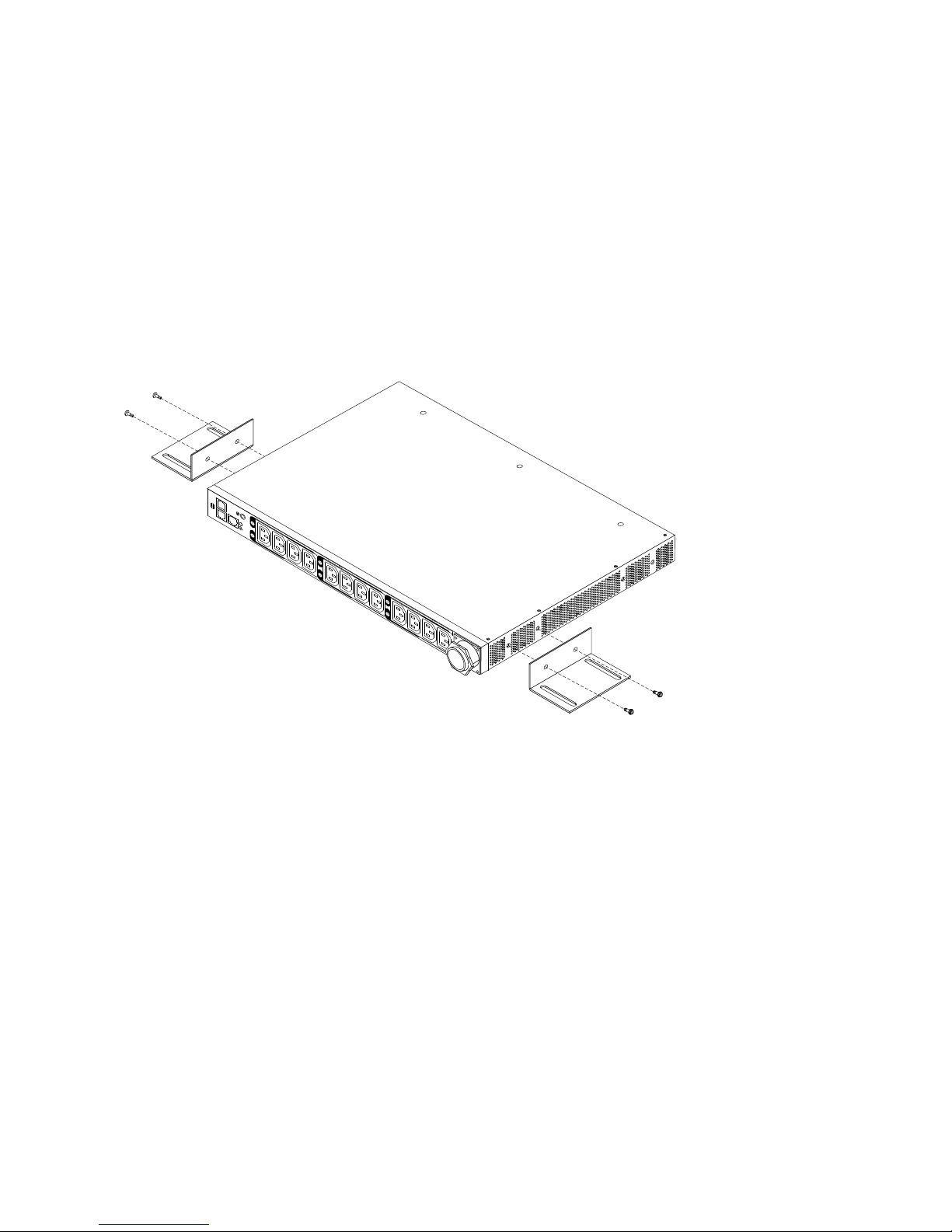
To install a PDU in the side of a rack cabinet by using the vertical mounting brackets, complete the following
steps:
1. Align the vertical mounting brackets to the front of the PDU and attach the brackets to the PDU with two
M3 x 5 screws per bracket. Use the screws that come with the PDU. You can install the PDU in a rack
cabinet with the power outlets facing the rear or the front of the rack cabinet.
2. Hold the PDU in the side of the rack cabinet, and attach the vertical mounting brackets to the side
braces with four M6 screws and nuts that come with the PDU.
10
1U C19 and C13 Switched and Monitored PDUs Installation and Maintenance Guide
a. Leave enough space to connect, route, and disconnect power cords.
b. If you are installing a cable-management bracket in the same side of the rack cabinet, leave enough
space between the outlet side of the PDU and the EIA mounting flanges for the cable-management
bracket installation.
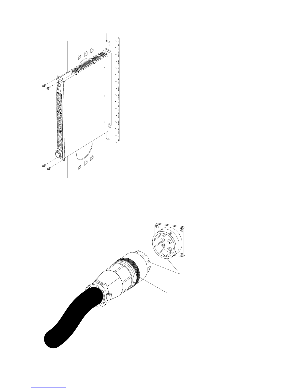
Attention: You must disconnect the main input power before you connect or disconnect the input
power cord from the PDU.
3. If the PDU comes with a detached power cord, connect the power cord. Align the connector on the
power cord that comes with the PDU with the connector on the front of the PDU, turning as necessary
for key alignment; then, turn the twist-lock on the connector clockwise until it locks into place.
Chapter 2. Installing the 1U PDU vertically in a rack cabinet 11
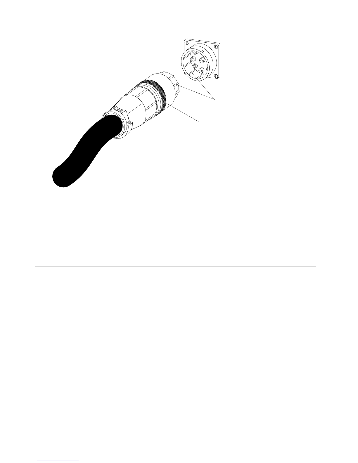
Key alignment
Twist lock
4. Route the power cord from the PDU toward the rack cabinet side braces; then, route the power cord
along a side brace toward the back of the rack cabinet, and secure the power cord with the cable straps
that come with the PDU.
5. Route the power cord toward a dedicated power source. Use the provided cable straps to secure the
power cord along the way. If the power cord must exit the rack cabinet to connect to a power source,
use the openings in the rack cabinet.
6. Connect the power cord to a properly wired and grounded dedicated power source. Then, you can
connect servers or rack PDUs in the rack cabinet to the power outlets on the PDU.
Installing the PDU in the side of an Enterprise rack cabinet only
Note: Removing the rack doors and side panels might make installation easier. See the rack cabinet
documentation for more information.
Review the documentation that comes with your rack cabinet for safety and cabling information. When you
install the PDU in a rack cabinet, observe the following precautions:
• Make sure that the room air temperature is below 35°C (95°F).
• Do not block any air vents; usually 15 cm (6 in.) of air space provides proper airflow.
• Connect all power cords to properly wired and grounded electrical outlets.
• Do not overload the power outlet when you install multiple devices in the rack.
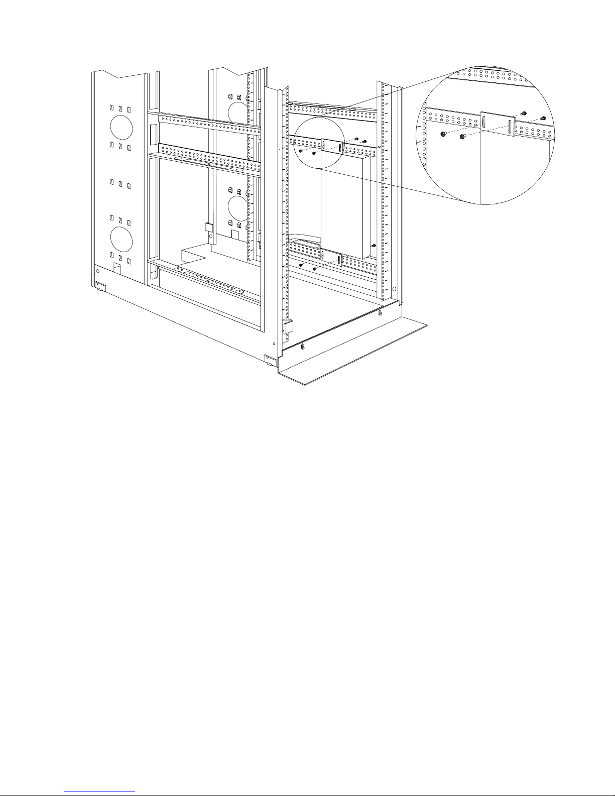
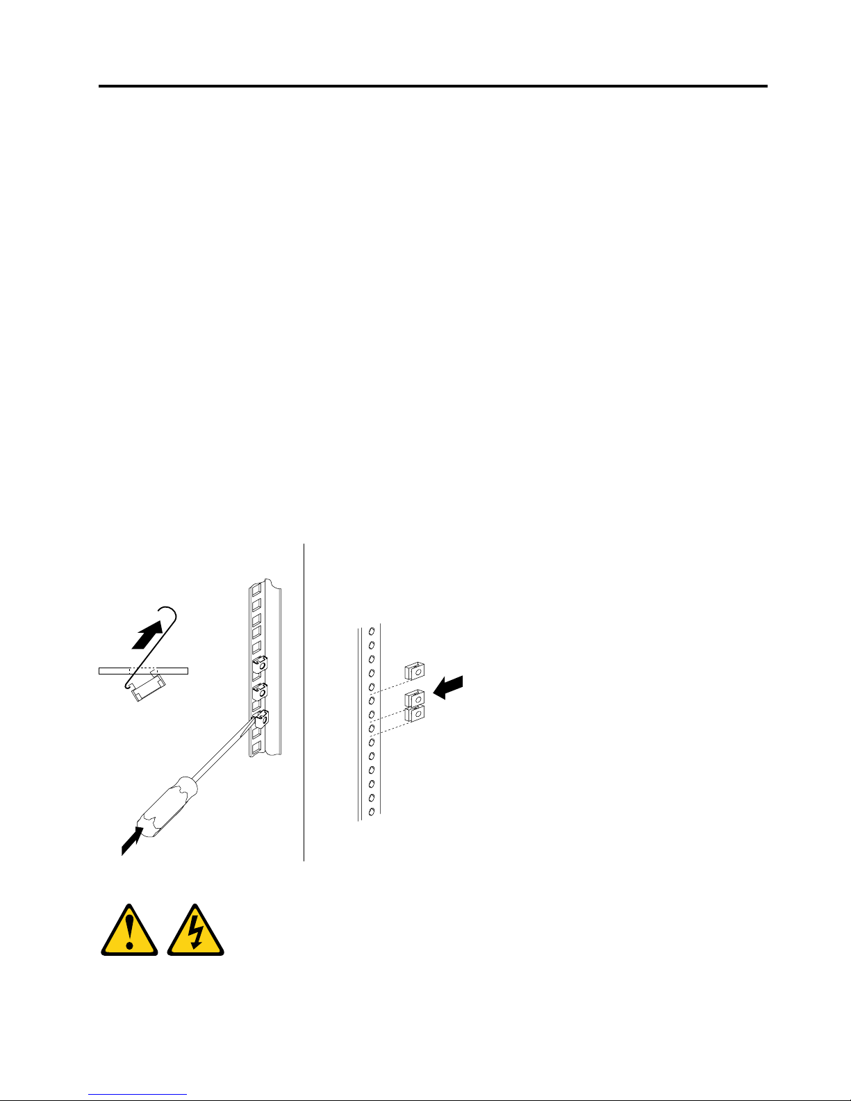
You must use clip nuts to install the mounting brackets. Clip nuts come with the PDU and are installed on the
rack mounting flanges, as shown in the following illustration.
12
1U C19 and C13 Switched and Monitored PDUs Installation and Maintenance Guide
21
20
19
To install the PDU in the 1U mounting space in the side of an Enterprise rack cabinet, complete the following
5
6
21
3
4
LAN
Short mounting bracket
steps:
1. Align the vertical-mounting brackets to the front of the PDU. Be sure to attach the brackets so that the
power outlets face the rear of the rack cabinet.
2. Attach the brackets to the PDU with two M3 x 5 screws per bracket. Use the screws that come with the
PDU.
3. Align the PDU with the opening in the side of the rack cabinet; then, while you hold the PDU in place,
attach the brackets to the rack-mounting flanges with four clip nuts and four M6 screws that come with
the PDU.
Chapter 2. Installing the 1U PDU vertically in a rack cabinet 13
5
6
21
3 4
LA
N
Attention: You must disconnect the main input power before you connect or disconnect the input
Key alignment
Twist lock
power cord from the PDU.
4. If the PDU comes with a detached power cord, connect the power cord. Align the connector on the
power cord that comes with the PDU with the connector on the front of the PDU, turning as necessary
for key alignment; then, turn the twist-lock on the connector clockwise until it locks into place.
14 1U C19 and C13 Switched and Monitored PDUs Installation and Maintenance Guide

5. Route the power cord from the PDU toward the rack cabinet side braces; then, route the power cord
along a side brace toward the back of the rack cabinet, and secure the power cord with the cable straps
that come with the PDU.
6. Route the power cord toward a dedicated power source. Use the provided cable straps to secure the
power cord along the way. If the power cord must exit the rack cabinet to connect to a power source,
use the openings in the rack cabinet.
7. Connect the power cord to a properly wired and grounded dedicated power source. Then, you can
connect servers or rack PDUs in the rack cabinet to the power outlets on the PDU.
8. Route all the other power cords neatly and secure the power cords with cable straps.
Chapter 2. Installing the 1U PDU vertically in a rack cabinet 15

16 1U C19 and C13 Switched and Monitored PDUs Installation and Maintenance Guide
Chapter 3. Installing the 1U PDU horizontally in a rack cabinet
Cage
nuts
Cage
nuts
Clip
nuts
Attention: Horizontal installation of a PDU is not supported during relocation or shipping of a rack cabinet.
You must remove any horizontally mounted PDUs from the EIA mounting space before you relocate the rack
cabinet.
Note: Removing the rack doors and side panels might make installation easier. See the rack cabinet
documentation for more information.
Review the documentation that comes with your rack cabinet for safety and cabling information. When you
install the PDU in a rack cabinet, observe the following precautions:
• Make sure that the room air temperature is below 35°C (95°F).
• Do not block any air vents; usually 15 cm (6 in.) of air space provides proper airflow.
• Plan the device installation starting from the bottom of the rack cabinet.
• Install the heaviest device in the bottom of the rack cabinet.
• Do not extend more than one device out of the rack cabinet at the same time.
• Connect all power cords to properly wired and grounded electrical outlets.
• Do not overload the power outlet when you install multiple devices in the rack cabinet.
Use cage nuts for rack cabinets with square holes, and use clip nuts for rack cabinets with round holes. If
your rack cabinet requires cage nuts, use a cage-nut-insertion tool or a flat-blade screwdriver to install them.
Statement 1
© Copyright Lenovo 2015, 2018 17
DANGER
5 6
2
1
3
4
LA
N
Short mounting bracket
Electrical current from power, telephone, and communication cables is hazardous.
To avoid a shock hazard:
• Do not connect or disconnect any cables or perform installation, maintenance, or reconfiguration
of this product during an electrical storm.
• Connect all power cords to a properly wired and grounded electrical outlet.
• Connect to properly wired outlets any equipment that will be attached to this product.
• When possible, use one hand only to connect or disconnect signal cables.
• Never turn on any equipment when there is evidence of fire, water, or structural damage.
• Disconnect the attached power cords, telecommunications systems, networks, and modems
before you open the device covers, unless instructed otherwise in the installation and
configuration procedures.
• Connect and disconnect cables as described in the following table when installing, moving, or
opening covers on this product or attached devices.
To Connect: To Disconnect:
1. Turn everything OFF.
2. First, attach all cables to devices.
3. Attach signal cables to connectors.
4. Attach power cords to outlet.
1. Turn everything OFF.
2. First, remove power cords from outlet.
3. Remove signal cables from connectors.
4. Remove all cables from devices.
5. Turn device ON.
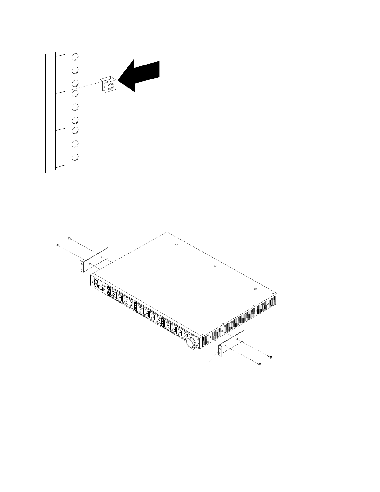
To install the PDU horizontally in a rack cabinet, complete the following steps:
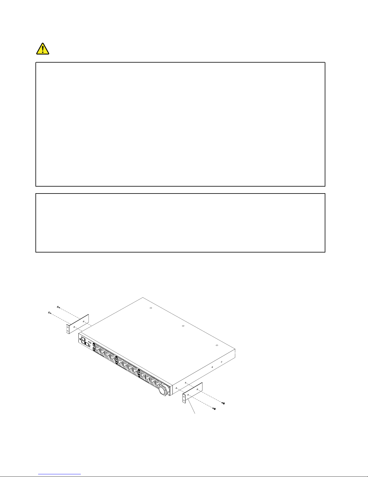
1. Align the short mounting brackets with the holes in the front of the PDU and attach the brackets to the
PDU with two M3 flat-head screws per bracket. Use the screws that come with the rack-mounting kit.
2. If the adjustable mounting rail is not assembled, complete the following steps to assemble it:
18
1U C19 and C13 Switched and Monitored PDUs Installation and Maintenance Guide
 Loading...