


 Loading...
ThinkServer
Installation and User Guide
Machine Types: 1043, 1044, 4010, and 4011
Note
Before using this information and the product it supports, be sure to read and understand the following:
•The Important Notices that comes with your product
•The Safety Information and the Warranty and Support Information on the documentation DVD that comes with your product
•Appendix C “Notices” on page 103
Fourth Edition (June 2011)
© Copyright Lenovo 2010, 2011.
LIMITED AND RESTRICTED RIGHTS NOTICE: If data or software is delivered pursuant a General Services Administration “GSA” contract, use, reproduction, or disclosure is subject to restrictions set forth in Contract No. GS-35F-05925.

Contents
Safety information . . . . . . . . . . |
iii |
Chapter 1. General information. . . . . |
1 |
Introduction . . . . . . . . . . . . . . . . . |
1 |
Notices and statements in the document . . . . . |
1 |
Related documentation . . . . . . . . . . . . |
2 |
Chapter 2. Server setup roadmap . . . |
3 |
Chapter 3. Features and |
|
technologies . . . . . . . . . . . . . . |
5 |
What is included with your server . . . . . . . . |
5 |
Features . . . . . . . . . . . . . . . . . . |
5 |
Specifications . . . . . . . . . . . . . . . . |
5 |
Software programs . . . . . . . . . . . . . . |
7 |
EasyStartup . . . . . . . . . . . . . . . |
7 |
EasyManage. . . . . . . . . . . . . . . |
7 |
Reliability, availability, and serviceability. . . . . . |
7 |
Chapter 4. Locating parts, controls, |
|
LEDs, and connectors . . . . . . . . . |
9 |
Front view . . . . . . . . . . . . . . . . . |
9 |
Rear view. . . . . . . . . . . . . . . . . . |
9 |
Front control panel . . . . . . . . . . . . . |
10 |
Locating server components . . . . . . . . . |
13 |
Locating parts on the system board . . . . . . |
13 |
Locating connectors on the backplane . . . . . |
16 |
Chapter 5. Installing, removing, or |
|
replacing hardware . . . . . . . . . . |
17 |
Guidelines . . . . . . . . . . . . . . . . |
17 |
Basic guidelines . . . . . . . . . . . . |
17 |
System reliability guidelines . . . . . . . . |
18 |
Handling static-sensitive devices . . . . . |
18 |
Working inside the server with the power on . |
19 |
Removing the server cover . . . . . . . . . . |
19 |
Installing, removing, or replacing optional hardware |
|
devices . . . . . . . . . . . . . . . . . |
20 |
Installing or removing a memory module. . . |
20 |
Removing or installing internal drives . . . . |
23 |
Installing or removing the riser card. . . . . |
32 |
Installing or removing a PCI card . . . . . . |
35 |
Removing or installing the Ethernet card . . . |
37 |
Installing, removing, or replacing hardware |
|
devices . . . . . . . . . . . . . . . . . |
38 |
Removing or installing the system board |
|
battery . . . . . . . . . . . . . . . . |
38 |
Removing or installing the RAID controller . . |
40 |
Removing or installing the heat sink |
|
assembly . . . . . . . . . . . . . . . |
52 |
Removing or installing the power supply. . . |
55 |
Removing or installing the microprocessor . . |
60 |
Completing the parts replacement . . . . . . . |
64 |
Installing the server cover . . . . . . . . |
64 |
Connecting the cables . . . . . . . . . . |
64 |
Turning on the server . . . . . . . . . . |
65 |
Updating the server configuration . . . . . |
65 |
Turning off the server . . . . . . . . . . |
65 |
Connecting external devices . . . . . . . |
66 |
Chapter 6. Configuring the server . . |
67 |
Using the Setup Utility program . . . . . . . . |
67 |
Starting the Setup Utility program . . . . . |
68 |
Introduction of the BIOS items. . . . . . . |
68 |
Using passwords . . . . . . . . . . . . |
75 |
RAID controllers . . . . . . . . . . . . . . |
76 |
Using the ThinkServer EasyStartup program . . . |
76 |
Before you use the EasyStartup DVD . . . . |
77 |
Setup and configuration . . . . . . . . . |
77 |
Configuring RAID . . . . . . . . . . . . |
78 |
Typical operating system installation . . . . |
78 |
Configuring the onboard SATA software RAID . . |
79 |
RAID information . . . . . . . . . . . . |
79 |
Starting the Intel Matrix Storage Manager |
|
program . . . . . . . . . . . . . . . |
79 |
Creating the RAID volume . . . . . . . . |
79 |
Deleting the RAID volume . . . . . . . . |
80 |
Rebuilding the RAID volume . . . . . . . |
80 |
Configuring the Gigabit Ethernet controller. . . . |
80 |
Updating the firmware. . . . . . . . . . . . |
80 |
Using the EasyUpdate Firmware Updater |
|
program . . . . . . . . . . . . . . . |
80 |
Installing the ThinkServer EasyManage program . |
81 |
Chapter 7. Troubleshooting. . . . . . |
83 |
Troubleshooting tables . . . . . . . . . . . |
83 |
DVD drive problems . . . . . . . . . . . |
83 |
General problems. . . . . . . . . . . . |
84 |
Hard disk drive problems . . . . . . . . . |
84 |
Intermittent problems . . . . . . . . . . |
84 |
Keyboard, mouse, or pointing-device |
|
problems . . . . . . . . . . . . . . . |
85 |
Memory problems . . . . . . . . . . . |
85 |
Microprocessor problems . . . . . . . . |
86 |
Monitor problems. . . . . . . . . . . . |
87 |
© Copyright Lenovo 2010, 2011 |
i |
Optional-device problems . . . . . . . . |
88 |
Power problems . . . . . . . . . . . . |
89 |
Serial port problems. . . . . . . . . . . |
90 |
Software problems . . . . . . . . . . . |
91 |
Universal Serial Bus (USB) port problems . . |
92 |
Solving power problems . . . . . . . . . . . |
92 |
Solving Ethernet controller problems . . . . . . |
92 |
Solving undetermined problems . . . . . . . . |
93 |
Event logs . . . . . . . . . . . . . . . . |
94 |
Viewing event logs without restarting the |
|
server . . . . . . . . . . . . . . . . |
94 |
System event log. . . . . . . . . . . . . . |
95 |
Diagnostic LEDs on the front control panel . . . |
95 |
Onboard debug digitron . . . . . . . . . . . |
95 |
Appendix A. RAID battery card |
|
assembly . . . . . . . . . . . . . . . |
97 |
Specifications . . . . . . . . . . . . . . . |
97 |
Battery life and data retention time . . . . . |
97 |
Appendix B. Getting help and
technical assistance . . . . . . . . . 99
Before you call. . . . . . . . . . . . . . . |
99 |
Using the documentation . . . . . . . . . . |
99 |
Getting help and information from the World Wide |
|
Web . . . . . . . . . . . . . . . . . . . |
99 |
Lenovo Support Web site . . . . . . . . . . |
100 |
Calling for service . . . . . . . . . . . . . |
100 |
Using other services . . . . . . . . . . . . |
101 |
Purchasing additional services . . . . . . . . |
101 |
Lenovo product service information for Taiwan . . |
101 |
Appendix C. Notices . . . . . . . |
. |
103 |
Trademarks . . . . . . . . . . . . . . |
. . |
104 |
Important notes . . . . . . . . . . . . |
. . |
104 |
Product recycling and disposal . . . . . . |
. . |
104 |
Particulate contamination . . . . . . . . |
. . |
105 |
Turkish statement of compliance . . . . . |
. . |
106 |
Battery return program . . . . . . . . . |
. . |
106 |
German Ordinance for Work gloss statement. |
. . |
107 |
Electronic emission notices. . . . . . . . |
. . |
107 |
Federal Communications Commission (FCC) |
|
|
Statement. . . . . . . . . . . . . |
. . |
107 |
Index. . . . . . . . . . . . . . . . |
. |
111 |
ii ThinkServer Installation and User Guide

Safety information
Before installing this product, read the Safety Information.
© Copyright Lenovo 2010, 2011 |
iii |
Important: Each caution and danger statement in this document is labeled with a number. This number is used to cross reference an English-language caution or danger statement with translated versions of the caution or danger statement in the Safety Information manual. For example, if a caution statement is labeled “Statement 1,” translations for this caution statement are in the Safety Information manual under “Statement 1.”
Be sure to read and understand all caution and danger statements in this document before you perform the procedures. Read and understand any additional safety information that comes with the server or an optional device before you install, remove, or replace the device.
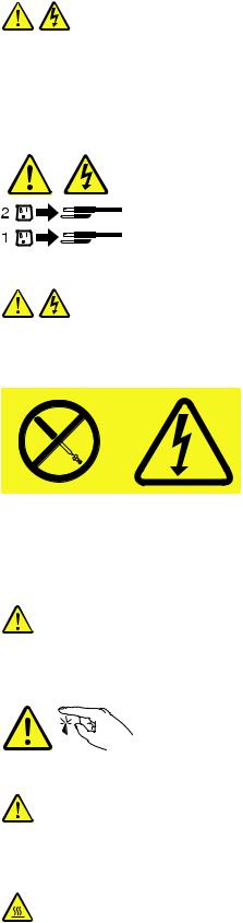
Statement 1
DANGER
Electrical current from power, telephone, and communication cables is hazardous.
To avoid a shock hazard:
•Do not connect or disconnect any cables or perform installation, maintenance, or reconfiguration of this product during an electrical storm.
•Connect all power cords to a properly wired and grounded electrical outlet.
•Connect to properly wired outlets any equipment that will be attached to this product.
•When possible, use one hand only to connect or disconnect signal cables.
•Never turn on any equipment when there is evidence of fire, water, or structural damage.
•Disconnect the attached power cords, telecommunications systems, networks, and modems before you open the device covers, unless instructed otherwise in the installation and configuration procedures.
•Connect and disconnect cables as described in the following table when installing, moving, or opening covers on this product or attached devices.
To Connect: |
To Disconnect: |
||
1. |
Turn everything OFF. |
1. |
Turn everything OFF. |
2. |
First, attach all cables to devices. |
2. |
First, remove power cords from outlet. |
3. |
Attach signal cables to connectors. |
3. |
Remove signal cables from connectors. |
4. |
Attach power cords to outlet. |
4. |
Remove all cables from devices. |
5. |
Turn device ON. |
|
|
|
|
|
|
iv ThinkServer Installation and User Guide
Statement 2
CAUTION:
When replacing the lithium battery, use only the battery recommended by the manufacturer. If your system has a module containing a lithium battery, replace it only with the same module type made by the same manufacturer. The battery contains lithium and can explode if not properly used, handled, or disposed of. Do not:
•Throw or immerse into water
•Heat to more than 100°C (212°F)
•Repair or disassemble
Dispose of the battery as required by local ordinances or regulations.
Statement 3
CAUTION:
When laser products (such as CD-ROMs, DVD drives, fiber optic devices, or transmitters) are installed, note the following:
•Do not remove the covers. Removing the covers of the laser product could result in exposure to hazardous laser radiation. There are no serviceable parts inside the device.
•Use of controls or adjustments or performance of procedures other than those specified herein might result in hazardous radiation exposure.
 DANGER
Some laser products contain an embedded Class 3A or Class 3B laser diode. Note the following.
Laser radiation when open. Do not stare into the beam, do not view directly with optical instruments, and avoid direct exposure to the beam.
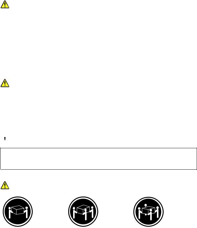
Statement 4
≥ 18 kg (39.7 lb) |
≥ 32 kg (70.5 lb) |
≥ 55 kg (121.2 lb) |
< 32 kg (70.5 lb) |
< 55 kg (121.2 lb) |
< 100 kg (220.5 lb) |
CAUTION:
Use safe practices when lifting.
© Copyright Lenovo 2010, 2011 |
v |
Statement 5
CAUTION:
The power control button on the device and the power switch on the power supply do not turn off the electrical current supplied to the device. The device also might have more than one power cord. To remove all electrical current from the device, ensure that all power cords are disconnected from the power source.
Statement 8
CAUTION:
Never remove the cover on a power supply or any part that has the following label attached.
Hazardous voltage, current, and energy levels are present inside any component that has this label attached. There are no serviceable parts inside these components. If you suspect a problem with one of these parts, contact a service technician.
Statement 11
CAUTION:
The following label indicates sharp edges, corners, or joints nearby.
Statement 12
CAUTION:
The following label indicates a hot surface nearby.
vi ThinkServer Installation and User Guide
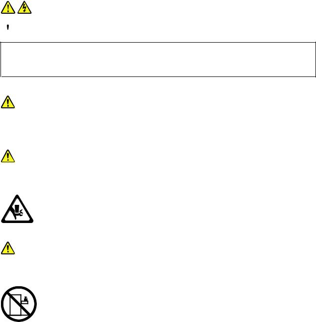
Statement 13
 DANGER
Overloading a branch circuit is potentially a fire hazard and a shock hazard under certain conditions. To avoid these hazards, ensure that your system electrical requirements do not exceed branch circuit protection requirements. Refer to the information that is provided with your device for electrical specifications.
Statement 15
CAUTION:
Make sure that the rack is secured properly to avoid tipping when the server unit is extended.
Statement 17
CAUTION:
The following label indicates moving parts nearby.
Statement 26
CAUTION:
Do not place any object on top of rack-mounted devices.
© Copyright Lenovo 2010, 2011 |
vii |
viii ThinkServer Installation and User Guide
Chapter 1. General information
This chapter provides some general information about your server.
This chapter contains the following topics:
•“Introduction” on page 1
•“Notices and statements in the document” on page 1
•“Related documentation” on page 2
Introduction
This Installation and User Guide is for your Lenovo® ThinkServer® RD230 server (machine types 1043, 1044, 4010, and 4011). This document contains the following information:
•Setting up and cabling the server
•Starting and configuring the server
•Installing options and replacing customer replaceable units (CRUs)
•Solving problems
The server comes with the ThinkServer EasyStartup DVD to help you configure the hardware, install device drivers, and install the operating system.
The server comes with a limited warranty. For information about the terms of the warranty and getting service and assistance, see the Warranty and Support Information on the documentation DVD that comes with your server.
To obtain the most up-to-date information about the server and other Lenovo products, go to: http://www.lenovo.com/thinkserver
Record information about the server in the following table. You will need this information when you register the server with Lenovo.
Product name |
ThinkServer RD230 |
Machine type |
1043, 1044, 4010, or 4011 |
Model number |
_____________________________________________ |
Serial number |
_____________________________________________ |
|
|
The model number and serial number are on the labels on the bottom of the server and on the front, visible through the bezel.
Notices and statements in the document
The caution and danger statements that appear in this document are also in the multilingual Safety Information. Each caution and danger statement in this document is labeled with a number. This number is used to cross reference an English-language caution or danger statement with translated versions of the caution or danger statement in the Safety Information. See “Related documentation” on page 2 for detailed information about how to get the various documentation for your server.
© Copyright Lenovo 2010, 2011 |
1 |

The following notices and statements are used in this document:
•Note: These notices provide important tips, guidance, or advice.
•Important: These notices provide information or advice that might help you avoid problems or inconvenient situations.
•Attention: These notices indicate potential damage to programs, devices, or data. An attention notice is placed just before the instruction or situation in which damage could occur.
•Caution: These statements indicate situations that can be potentially hazardous to you. A caution statement is placed just before the description of a potentially hazardous procedure step or situation.
•Danger: These statements indicate situations that can be potentially lethal or extremely hazardous to you. A danger statement is placed just before the description of a potentially lethal or extremely hazardous procedure step or situation.
Related documentation
The Lenovo documentation DVD, which comes with your server, contains documentation for the server in Portable Document Format (PDF). To view the documentation on the documentation DVD, you need to have the Adobe Reader 5.0 program or later installed, or the xpdf, which comes with Linux® operating systems.
The following table provides information about the general descriptions of the various documentation provided with your server and how to obtain all the documentation.
Table 1. Related documentation for the server
Documentation |
Description |
Location |
|
|
|
Hardware Maintenance |
This document provides diagnostic |
This document is in English and posted |
Manual |
information, parts listing, replacement |
on the Lenovo Support Web site at |
|
procedures for all CRUs, and replacement |
http://www.lenovo.com/support. |
|
procedures for other field replaceable units |
|
|
(FRUs) replaced by trained service personnel. |
|
|
|
|
Important Notices |
This document includes safety and legal |
This document is printed out and |
|
notices that you are expected to read before |
provided in server packaging. |
|
using the server. |
|
|
|
|
Rack Installation |
This document provides instructions on how |
The English version of this document is |
Instructions |
to install your server in a rack. |
printed out and provided in the server |
|
|
packaging. Additional languages are |
|
|
provided on the documentation DVD |
|
|
and on the Lenovo Support Web site: |
|
|
http://www.lenovo.com/support |
|
|
|
Read Me First |
This document directs you to the |
This document is printed out and |
|
documentation DVD for complete warranty |
provided in server packaging. |
|
and support information. |
|
|
|
|
Safety Information |
This document includes translations of all |
Available on the documentation DVD |
|
safety statements used in the ThinkServer |
|
|
documentation. |
|
|
|
|
Warranty and Support |
This document includes the warranty |
Available on the documentation DVD |
Information |
statement and information about how to |
|
|
contact Lenovo Support. |
|
|
|
|
Note: You can obtain all the documentation in PDF for your server from the Lenovo Support Web site at http://www.lenovo.com/support.
2 ThinkServer Installation and User Guide

Chapter 2. Server setup roadmap
This chapter provides a general roadmap to guide you through setting up your server.
The server setup procedure varies depending on the configuration of the server when it was delivered. In some cases, the server is fully configured and you just need to connect the server to the network and an electrical outlet, and then you can turn on the server. In other cases, the server needs to have hardware features installed, requires hardware and firmware configuration, and requires the operating system to be installed.
Table 2. Server setup roadmap
Task |
Where to find the information |
|
|
Unpack |
Chapter 3 “Features and technologies” on page 5 |
|
|
Install hardware |
Chapter 5 “Installing, removing, or replacing hardware” on page 17 |
|
|
Install the server in the rack |
The Rack Installation Instructions manual is printed and also included on the |
|
documentation DVD. |
|
|
Connect the Ethernet cable |
“Rear view” on page 9 |
and power cord |
|
|
|
Turn on the server to verify |
“Turning on the server” on page 65 |
operation |
|
|
|
Review the BIOS settings |
“Starting the Setup Utility program” on page 68 |
and customize as needed |
|
|
|
Configure RAID (onboard |
“RAID controllers” on page 76 |
SATA RAID or the installed |
|
SAS RAID adapter) |
|
|
|
Check for firmware updates |
“Using the EasyUpdate Firmware Updater program” on page 80 |
|
|
Install operating system and |
“Using the ThinkServer EasyStartup program” on page 76 |
basic drivers |
|
|
|
Install any additional drivers |
Refer to the instructions that came with the hardware option. |
needed for added features |
|
|
|
Configure Ethernet settings |
See the operating system help. This step is not required if the operating system was |
in the operating system |
installed using the ThinkServer EasyStartup program. |
|
|
Install remote management |
“Installing the ThinkServer EasyManage program” on page 81 |
applications |
|
|
|
Install applications |
Refer to the documentation that comes with the applications that you want to install. |
|
|
© Copyright Lenovo 2010, 2011 |
3 |
4 ThinkServer Installation and User Guide

Chapter 3. Features and technologies
What is included with your server
The RD230 server package includes the server, a power cord, documentation, the documentation DVD, and software media.
Features
The RD230 server offers the following features and technologies:
•Microprocessor(s): The server supports up to two Intel® Xeon® dual-core, quad-core, or hex-core microprocessors.
•BIOS: The server firmware defines a standard interface between the operating system, platform firmware, and external devices.
•EasyStartup DVD: The ThinkServer EasyStartup program guides you through the configuration of the hardware, the redundant array of independent disks (RAID) controller, and the installation of the operating system and device drivers.
•Integrated network support: The server comes with two integrated single-port Gigabit Ethernet controllers and each supports connection to a 10 Mbps, 100 Mbps, or 1000 Mbps network. For more information, see “Configuring the Gigabit Ethernet controller” on page 80.
•Large data-storage capacity and hot-swap capability: Some hot-swap server models support four 3.5-inch hot-swap hard disk drives. With the hot-swap feature, you can add, remove, or replace hard disk drives without turning off the server.
•Large system-memory capacity: The server supports up to 64 GB of system memory. The memory module supports error correcting code (ECC) for up to eight industry-standard single-rank or dual-rank, 1333 MHz, DDR3 (third-generation double-data-rate) registered synchronous dynamic random access memory (SDRAM) dual inline memory modules (DIMMs).
•High-performance graphics controller: The server comes with an onboard high-performance graphics controller that supports high resolutions and includes many performance-enhancing features for the operating-system environment.
•Redundant connection: The two onboard network interface controllers (NIC) provide a failover capability to a redundant Ethernet connection. If a problem occurs with the primary Ethernet connection, all Ethernet traffic that is associated with the primary connection is automatically switched to the redundant NIC. If the applicable device drivers are installed, this switching occurs without data loss and without user intervention.
•Intelligent Platform Management Interface (IPMI) 2.0: The command-line interface provides direct access to server management functions through the IPMI 2.0 protocol. Use the command-line interface to issue commands to control the server power, view system information, and identify the server. You can also save one or more commands as a text file and run the file as a script.
•RAID support: The server supports the onboard SATA software RAID and an add-on SAS RAID card (ThinkServer 8708ELP SAS RAID Adapter, ThinkServer 8708EM2 RAID Adapter, or ThinkServer RAID 700 Adapter), which are required for you to use the hot-swap SATA or SAS hard disk drives and to create the RAID configurations.
Specifications
The following information is a summary of the features and specifications of the server. Depending on the server model, some features might not be available, or some specifications might not apply.
© Copyright Lenovo 2010, 2011 |
5 |

Table 3. Features and specifications
Microprocessor(s): Supports up to |
Optical drive: |
Environment: |
|||
two Intel Xeon dual-core, quad-core, |
• Slim DVD/RW |
• |
Air temperature: |
||
or hex-core microprocessors. For the |
|
– |
Server on: 10°C to 35°C (50°F |
||
|
|
||||
specific type and speed information |
Hard disk drive expansion bays |
|
|
to 95°F); altitude: 0 to 914.4 m |
|
about the microprocessor, use |
|
|
(3 000 ft) |
||
(depending on the model): |
|
|
|||
the Setup Utility program. See |
|
– |
Server on: 10°C to 32°C (50°F |
||
|
|
||||
“Using the Setup Utility program” on |
Up to four 3.5-inch SATA or SAS hard |
|
|
to 89.6°F); altitude: 914.4 m (3 |
|
page 67. For a list of the supported |
|
|
000 ft) to 2 133.6 m (7 000 ft) |
||
disk drives |
|
|
|||
microprocessors for your server, go to |
|
– |
Server off: 10°C to 43°C (50°F |
||
|
|
||||
http://www.lenovo.com/thinkserver. |
Expansion slots: |
|
|
to 109.4°F); maximum altitude: |
|
On the ThinkServer systems page, |
|
|
2 133.6 m (7 000 ft) |
||
|
|
|
|||
click Products Options |
• Three PCI Express slots on the |
|
– |
Shipping: -40°C to 60°C (-104°F |
|
ThinkServer Processors. |
system board and the PCI Express |
|
|
to 140°F) |
|
|
|
x16 slot is for a riser card (there is |
• |
Humidity: |
|
Memory modules: |
one PCI Express x16 slot on the |
|
– Server on: 8-90%, |
||
• |
Minimum system memory: 2 GB |
riser card) |
|
|
non-condensing |
• |
Maximum system memory: 64 GB |
|
|
– Server off: 8-90%, |
|
|
(eight memory slots, each with one |
Power supply: Single 600-watt |
|
|
non-condensing |
|
8 GB RDIMM installed) |
power supply |
|
– |
Shipping and storage: up to |
• |
Types: ECC, 1333 MHz, DDR3 |
|
|
|
93%, non-condensing |
|
registered SDRAM DIMMs only |
System fans: Five system fans |
• |
Particulate contamination: |
|
• |
Slots: Eight dual inline memory |
with automatic energy-saving noise |
|
Attention: Airborne particulates |
|
|
module (DIMM) slots |
reduction technology |
|
||
• Supports 2 GB, 4 GB, and 8 GB |
|
|
and reactive gases acting alone |
||
|
RDIMMs |
Integrated functions: |
|
or in combination with other |
|
|
|
• Two single-port Gb Ethernet |
|
environmental factors such as |
|
Integrated graphics card: |
controllers |
|
humidity or temperature might |
||
• 8 MB video memory |
• Six USB 2.0 connectors (two front |
|
pose a risk to the server. |
||
|
|
and four rear) |
|
|
|
Size: |
• Two RJ-45 Ethernet connectors |
|
|
|
|
• |
Height: 43.6 mm (1.72 inches) |
• One serial port |
|
|
|
• |
Width: 436 mm (17.17 inches) |
• One Video Graphics Array (VGA) |
|
|
|
• |
Depth: 568 mm (22.36 inches) |
monitor connector |
|
|
|
•Maximum weight: 17 kg (37.48 lb) when fully configured
6 ThinkServer Installation and User Guide

Table 3. Features and specifications (continued)
RAID controllers: |
Electrical input |
Notes: |
||
• Onboard SATA Software RAID |
• Input voltage: |
1. Power consumption and heat |
||
• ThinkServer 8708ELP SAS RAID |
– |
Low range: |
output vary depending on the |
|
number and type of optional |
||||
Adapter |
|
|
||
|
Minimum: 100 V ac |
features installed and the |
||
• ThinkServer 8708EM2 RAID |
|
|||
|
Maximum: 127 V ac |
power-management optional |
||
Adapter |
|
features in use. |
||
|
Input frequency range: 50 to |
|||
• ThinkServer RAID 700 Adapter |
|
2. The sound levels were measured |
||
|
60 Hz |
|||
|
|
in controlled acoustical |
||
|
– |
High range: |
||
|
environments according to |
|||
|
|
Minimum: 200 V ac |
the procedures specified by the |
|
|
|
American National Standards |
||
|
|
Maximum: 240 V ac |
||
|
|
Institute (ANSI) S12.10 and |
||
|
|
Input frequency range: 50 to |
ISO 7779 and are reported in |
|
|
|
accordance with ISO 9296. |
||
|
|
60 Hz |
||
|
|
Actual sound-pressure levels in a |
||
|
|
|
||
|
|
|
given location might exceed the |
|
|
|
|
average values stated because |
|
|
|
|
of room reflections and other |
|
|
|
|
nearby noise sources. The |
|
|
|
|
noise emission level stated |
|
|
|
|
is the declared (upper limit) |
|
|
|
|
sound-power level, in bels, for a |
|
|
|
|
random sample of system. |
|
|
|
|
3. There is no keyboard connector |
|
|
|
|
or mouse connector on the |
|
|
|
|
server. You can connect a USB |
|
|
|
|
keyboard and USB mouse to |
|
|
|
|
the server by using the USB |
|
|
|
|
connectors. |
|
|
|
|
|
|
Software programs
Lenovo provides software to help get your server up and running.
EasyStartup
The ThinkServer EasyStartup program simplifies the process of configuring RAID and installing supported Microsoft® Windows® and Linux operating systems and device drivers on your server. The EasyStartup program is provided with your server on the ThinkServer EasyStartup DVD. The DVD is self-starting (bootable). The user guide for the EasyStartup program is on the DVD and can be accessed directly from the program interface. For additional information, see “Using the ThinkServer EasyStartup program” on page 76.
EasyManage
The ThinkServer EasyManage Agent enables this server to be managed by the centralized console of an EasyManage Core Server over the network. The ThinkServer EasyManage Agent is supported on 32-bit and 64-bit Windows, Red Hat, and SUSE operating systems.
Reliability, availability, and serviceability
Reliability, availability, and serviceability (hereafter referred to as RAS) are three important server design features. The RAS features help you to ensure the integrity of the data stored on the server, the availability of the server when you need it, and the ease with which you can diagnose and correct problems.
Chapter 3. Features and technologies 7
The server has the following RAS features:
•Advanced Configuration and Power Interface (ACPI)
•Advanced Desktop Management Interface (DMI)
•Automatic memory downsizing on error detection
•Automatic restart on non-maskable interrupt (NMI)
•Availability of microcode level
•Built-in, menu-driven setup, system configuration, and RAID configuration
•Built-in monitoring for fan, temperature, and voltage
•Cooling fans with speed-sensing capability
•ECC DDR3 SDRAM with Serial Presence Detect (SPD)
•Error codes and messages to help you identify problems
•Generating error logs for the power-on self-test (POST) failures
•Hot-swap SAS hard disk drives
•Integrated Ethernet controllers
•Intelligent Platform Management Interface (IPMI) 2.0
•Power-on self-test (POST)
•Redundant Ethernet connection with failover capability (requires an optional Ethernet card)
•Standby voltage for system-management features and monitoring
•System-error light-emitting diode (LED) on the front panel
•Vital product data (VPD), including the serial number information and replacement part numbers, stored in the nonvolatile memory for easier remote maintenance
8 ThinkServer Installation and User Guide
Chapter 4. Locating parts, controls, LEDs, and connectors
This chapter provides information to help you locate your server parts, controls, light-emitting diodes (LEDs), and connectors.
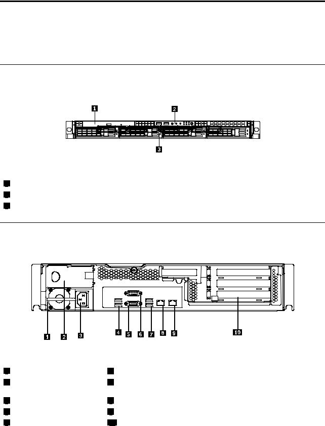
Front view
The following illustration shows the drives and parts on the front of the server.
Figure 1. Front view of the server |
|
1 |
Slim optical drive |
2 |
Front control panel (see “Front control panel” on page 10) |
3 |
Mounting point for 3.5-inch hard disk drive |
Rear view
The following illustration shows the locations of the connectors and parts on the rear of the server.
Figure 2. Rear view of the server
1 |
Power supply 1 |
2 Power supply 2 bay (blank and covered by a bay bezel)
3 |
Power cord connector |
4 |
USB connectors (1 and 2) |
5 |
VGA monitor connector |
6 Serial port
7 USB connectors (3 and 4)
8 Ethernet connector 1
9 Ethernet connector 2 (share with MGMT)
10 PCI expansion slot
© Copyright Lenovo 2010, 2011 |
9 |
Connector |
Description |
Power cord connector |
Used to connect the power cord. |
Ethernet connector |
Used to attach an Ethernet cable for a local area network (LAN). |
Serial port |
Used to attach a device that uses a 9-pin serial port. |
USB connector |
Used to attach a device that uses a USB connector, such as a USB keyboard |
|
or a USB mouse. |
VGA monitor connector |
Used to attach a VGA monitor or other devices that use a VGA monitor connector. |
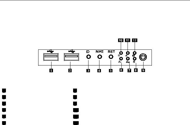
Front control panel
This section provides information about the front control panel of the server.
The following illustration helps you identify the connectors, controls, and LEDs on the front control panel of your server.
Figure 3. Front control panel locations
1 |
USB connector |
2 |
USB connector |
3 |
ID button |
4 |
NMI button |
5 |
Reset button |
6 |
Ethernet 1 status LED |
7 |
Ethernet 2 status LED |
8 |
Hard disk drive status LED |
9 |
Power button and LED |
10System ID LED
11System status LED
12LED (will not be used in this server)
The following table describes the meaning of the LEDs on the front control panel.
Table 4. Front control panel LEDs
LED |
State |
Color |
Description |
|
|
|
|
|
|
Power LED |
On |
Green |
The server power is on. |
|
|
|
|
|
|
|
Blinking |
Green |
The server power is under S1. |
|
|
|
|
|
|
|
Off |
Off |
The server power is off. |
|
|
|
|
|
|
Hard disk drive |
Off |
Off |
The hard disk drive is not active. |
|
LED |
|
|
|
|
Blinking |
Green |
The hard disk drive is active. |
||
|
||||
|
|
|
|
|
Ethernet 1 |
On |
Green |
LAN is linked. |
|
status LED |
|
|
|
|
Blinking |
Green |
LAN is active. |
||
|
||||
|
|
|
|
|
|
Off |
Off |
LAN is not linked. |
|
|
|
|
|
10 ThinkServer Installation and User Guide
Table 4. Front control panel LEDs (continued)
LED |
State |
Color |
Description |
|
|
|
|
|
|
Ethernet 2 |
On |
Green |
LAN is linked. |
|
status LED |
|
|
|
|
Blinking |
Green |
LAN is active. |
||
|
||||
|
|
|
|
|
|
Off |
Off |
LAN is not linked. |
|
|
|
|
|
|
System status |
On |
Red |
Failure. Over temperature or over voltage. |
|
LED |
|
|
|
|
Off |
Off |
No failure. |
||
|
||||
|
|
|
|
|
ID LED |
On |
Blue |
System is identified. |
|
|
|
|
|
|
|
Off |
Off |
System is not identified. |
|
|
|
|
|
Each hard disk drive has two status LEDs on the front. The green LED 1 (bottom) indicates activity and the amber LED 2 (top) indicates the RAID status.
Notes: If the onboard SATA and onboard SATA software RAID are configured, note the following:
•The SGPIO connector of the 4–port SATA cable in the chassis should be connected to the J45 connector on the system board. See “Locating parts on the system board” on page 13.
•The function of the amber LED 2 is only available after you enter the operating system.
Table 5. Hard disk drive LEDs
|
Green LED 1 |
|
Description |
(bottom) |
Amber LED 2 (top) |
|
|
|
Hard disk drive is not present. |
Off |
Off |
|
|
|
Hard disk drive is present but is not active. |
On |
Off |
|
|
|
Hard disk drive is present and active. |
Blinking |
Off |
|
|
|
Server is in the process of locating the hard disk drive. |
On |
Blinking |
|
|
|
RAID has failed. |
Off |
On |
|
|
|
Hard disk drive is rebuilding. |
Blinking |
Blinking |
|
|
|
Note: For some models, the hard disk drive status information might be different from the information listed in the above table. For these server models, refer to the following two tables for the hard disk drive LED status.
Table 6. Hard disk drive LEDs for the onboard SATA and onboard SATA software RAID configurations (some models)
|
Green LED 1 |
|
Description |
(bottom) |
Amber LED 2 (top) |
|
|
|
Hard disk drive is not present. |
Off |
Off |
|
|
|
Hard disk drive is present but is not active. |
On |
Off |
|
|
|
Hard disk drive is present and active. |
Blinking |
Off |
|
|
|
Server is in the process of locating the hard disk drive. |
On |
Off |
|
|
|
RAID has failed. |
On |
Off |
|
|
|
Hard disk drive is rebuilding. |
Blinking |
Off |
|
|
|
Chapter 4. Locating parts, controls, LEDs, and connectors 11

Table 7. Hard disk drive LEDs for the add-on SAS RAID adapter configuration (some models)
|
Green LED 1 |
|
Description |
(bottom) |
Amber LED 2 (top) |
|
|
|
Hard disk drive is not present. |
Off |
Off |
|
|
|
Hard disk drive is present but is not active. |
On |
Off |
|
|
|
Hard disk drive is present and active. |
Blinking |
Off |
|
|
|
Server is in the process of locating the hard disk drive. |
Blinking |
Blinking |
|
|
|
RAID has failed. |
Off |
On |
|
|
|
Hard disk drive is rebuilding. |
Blinking |
Blinking |
|
|
|
The Ethernet 1 and Ethernet 2 connectors have two status LEDs that indicate the LAN connection and activity of the connection.
Table 8. Ethernet LEDs
LED |
State |
Color |
Description |
|
|
|
|
RJ-45 linkage/activity (left) |
On |
Green |
10/100/1000 Mb linked |
|
|
|
|
|
Blinking |
Green |
10/100/1000 Mb activity |
|
|
|
|
|
Off |
Off |
No LAN connection. |
|
|
|
|
RJ-45 speed (right) |
On |
Amber |
1000 Mb linked and active |
|
|
|
|
|
On |
Green |
100 Mb linked and active |
|
|
|
|
|
Off |
Off |
10 Mb mode or no LAN connection. |
|
|
|
|
12 ThinkServer Installation and User Guide
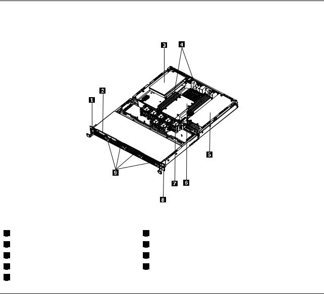
Locating server components
The following illustration shows the locations of the major components in your server.
Figure 4. Server component locations
1 |
Left handle of the chassis |
2 |
Slim optical drive |
3 |
PCI card |
4 |
Memory modules |
5 |
Power supply assembly |
6 |
Heat sink assembly and microprocessor(s) underneath |
7 |
System fans |
8 |
Right handle of the chassis |
9 |
Mounting points for the 3.5-inch hard disk drives |
Locating parts on the system board
The following illustrations show the locations of the parts on the system board.
Chapter 4. Locating parts, controls, LEDs, and connectors 13
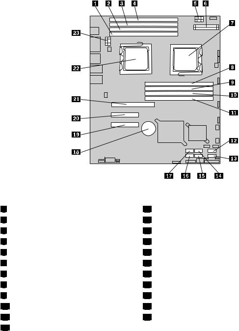
Figure 5. Locating major parts on the system board
1 |
Memory slot (CPU1 DIMM CHA1) |
2 |
Memory slot (CPU1 DIMM CHA0) |
3 |
Memory slot (CPU1 DIMM CHB0) |
4 |
Memory slot (CPU1 DIMM CHC0) |
5 |
Power connector 2 (for CPU0) |
6 |
24-pin power connector for the system board |
7 |
Microprocessor (CPU0) |
8 |
Memory slot (CPU0 DIMM CHA1) |
9 |
Memory slot (CPU0 DIMM CHA0) |
10Memory slot (CPU0 DIMM CHB0)
11Memory slot (CPU0 DIMM CHC0)
12SATA connector 0
13 |
14 |
15 |
16 |
17 |
18 |
19 |
20 |
21 |
22 |
23 |
SATA connector 1
SATA connector 2
SATA connector 3
SATA connector 5
SATA connector 4
System board battery
PCI Express x8 slot (for the riser card) PCI Express x8 slot (for the riser card) PCI Express x16 slot (for the riser card) Microprocessor (CPU1)
Power connector 3 (for CPU1)
14 ThinkServer Installation and User Guide
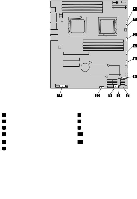
Figure 6. Locating other connectors on the system board
1 |
J47 (system fan 1 connector) |
2 |
J48 (system fan 2 connector) |
3 |
J50 (system fan 3 connector) |
4 |
J56 (system fan 4 connector) |
5 |
J49 (system fan 5 connector) |
6 |
J19 (front USB connector) |
7 J35 (for front control cable)
8 JP1 (Clear CMOS jumper)
9 USB 2 connector
10 J45 connector (for the SGPIO connector of the 4–port SATA cable)
11 JP8 (COM2 connector)
The following table introduces the jumper switches on the system board.
Table 9. Jumper settings
Jumper |
Position |
Description |
|
|
|
JP1: Clear |
Pins 1-2 |
The default position at which the jumper is placed on pins 1-2 during the normal |
CMOS |
|
operation of the system. |
|
|
|
|
Pins 2-3 |
If the jumper is placed on pins 2-3, when the jumper is moved back to the default |
|
|
position, the settings of CMOS will be cleared automatically at the next startup. |
|
|
|
Note: Before clearing the CMOS, turn off the server and disconnect the power cord. Move the jumper from pins 1-2 to pins 2-3. Wait more than five minutes and then move the jumper back to the normal position (pins 1-2) to clear CMOS.
Chapter 4. Locating parts, controls, LEDs, and connectors 15
Locating connectors on the backplane
The following illustration shows the connector locations on the backplane.
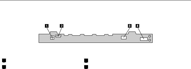
Figure 7. Backplane connector locations
1 |
Power connector 2 |
2 |
Power connector 1 |
3 |
Optical drive power connector |
4 |
Mini-SAS signal cable connector |
16 ThinkServer Installation and User Guide

Chapter 5. Installing, removing, or replacing hardware
This chapter provides instructions on how to install, remove, or replace hardware for your server.
This chapter contains the following topics:
•“Guidelines” on page 17
•“Removing the server cover” on page 19
•“Installing, removing, or replacing optional hardware devices” on page 20
•“Installing, removing, or replacing hardware devices” on page 38
•“Completing the parts replacement” on page 64
Guidelines
This section provides some guidelines that you should read and understand before using your server.
Basic guidelines
Before you use the server, be sure to read and understand the following guidelines:
•Be sure to read and understand the Safety Information and the Warranty and Support Information on the documentation DVD that comes with your product, and “Guidelines” on page 17. These information will help you work safely. To obtain a copy of the publications, go to:
http://www.lenovo.com/support
•When you install your new server, take the opportunity to download and apply the most recent firmware updates. This step will help you to ensure that any known issues are addressed and the server is ready to function at optimal performance. To download firmware updates for your server, do the following:
1.Go to http://www.lenovo.com/support.
2.Click Download & Drivers ThinkServer and then follow the instructions on the Web page to download firmware updates for your server.
•Observe good housekeeping in the area where you are working. Put removed covers and other parts in a safe place.
•If you must turn on the server while the server cover is removed, make sure that no one is near the server and that no tools or other objects have been left inside the server.
•Do not attempt to lift an object that you think is too heavy for you. If you have to lift a heavy object, observe the following precautions:
–Make sure that you can stand safely without slipping.
–Distribute the weight of the object equally between your feet.
–Use a slow lifting force. Never move suddenly or twist when you lift a heavy object.
–To avoid straining the muscles in your back, lift by standing or by pushing up with your leg muscles.
•Make sure that you have an adequate number of properly grounded electrical outlets for the server, monitor, and other devices.
•Back up all important data before you make changes to drives.
•Have a small flat-blade screwdriver available.
•To view the error LEDs on the system board and internal components, leave the server connected to power.
© Copyright Lenovo 2010, 2011 |
17 |
•You do not have to turn off the server to install or replace hot-swap fans, redundant hot-swap ac power supplies, or hot-plug USB devices. However, you must turn off the server before performing any steps that involve installing, removing, or replacing adapter cables or non-hot-swap optional devices or components.
•After completing any installation, removal, or replacement procedure, reinstall all safety shields, guards, labels, and ground wires.
•For a list of supported optional devices for the server, go to http://www.lenovo.com/thinkserver.
•When working inside the server, you might find some tasks easier if you lay the server on its side.
System reliability guidelines
To help ensure proper cooling and system reliability, make sure that you follow these guidelines:
•Every drive bay has an internal drive installed or an Electro Magnetic Compatibility (EMC) shield installed.
•If the server has redundant power, every power supply bay has a power supply assembly installed.
•Leave adequate space around the server to make sure that the server cooling system works well.
•Properly route the cables. For some options, such as PCI cards, follow the cabling instructions that come with the options.
•Make sure that you replace a failing fan within 48 hours.
•When replacing a hot-swap drive, install the new hot-swap drive within two minutes of removal.
•Do not remove any air duct or air baffles while the server is running. Operating the server without the air duct or air baffles might cause the microprocessor to overheat.
•The second microprocessor socket always contains either a microprocessor socket cover or a microprocessor.
Handling static-sensitive devices
Attention:
Do not open the static-protective package containing the new part until the defective part has been removed from the server and you are ready to install the new part. Static electricity, although harmless to you, can seriously damage server components and parts.
When you handle server parts and components, take these precautions to avoid static-electricity damage:
•Limit your movement. Movement can cause static electricity to build up around you.
•Wear an electrostatic-discharge wrist strap, if one is available.
•Always carefully handle the parts and other components (such as PCI cards, memory modules, system boards, and microprocessors) by its edges or its frame. Do not touch solder joints, pins, or exposed circuitry.
•Prevent others from touching the parts and other computer components.
•Before you replace a new part, touch the static-protective package containing the new part to a metal expansion-slot cover or other unpainted metal surface on the server for at least two seconds. This reduces static electricity from the package and your body.
•Remove the new part from the static-protective package and directly install it in the server without placing it on any other surface. If it is hard for you to do this in your specific situation, place the static-protective package of the new part on a smooth, level surface, and then place the new part on the static-protective package.
•Do not place the part on the server cover or other metal surface.
•Take additional care when handling devices during cold weather. Heating reduces indoor humidity and increases static electricity.
18 ThinkServer Installation and User Guide
Working inside the server with the power on
Attention:
Static electricity that is released to internal server components when the server is turned on might cause the server to halt, which might result in the loss of data. To avoid this potential problem, always use an electrostatic-discharge wrist strap or other grounding system when you work inside the server with the power on.
The server supports hot-swap devices and is designed to operate safely while it is turned on and the cover is removed. Follow these guidelines when you work inside the server with the power on:
•Avoid wearing loose-fitting clothing on your forearms. Button long-sleeved shirts before working inside the server; do not wear cuff links while you are working inside the server.
•Do not allow your necktie or scarf to hang inside the server.
•Remove jewelry, such as bracelets, necklaces, rings, and loose-fitting wrist watches.
•Remove items from your shirt pocket, such as pens and pencils. These items might fall into the server as you lean over it.
•Avoid dropping any metallic objects into the server, such as paper clips, hairpins, and screws.
Removing the server cover
Attention: Do not open your server or attempt any repair before reading and understanding the “Safety information” on page iii and “Guidelines” on page 17.
This section provides instructions on how to remove the server cover.
Attention: For proper cooling and airflow, install the server cover before turning on the server. Operating the server for more than 30 minutes with the server cover removed might damage server components.
To remove the server cover, do the following:
1.Remove all media from the drives. Then, turn off all attached devices and the server.
2.Disconnect all power cords from electrical outlets.
3.Disconnect the power cord(s), Input/Output (I/O) cables, and all other cables that are connected to the server.
Chapter 5. Installing, removing, or replacing hardware 19
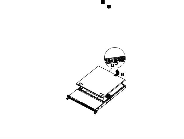
4.Loosen the thumbscrew in the rear of the server cover 1 . Then, slide the server cover to the rear until you can lift it up to completely remove it from the chassis 2 .
Notes:
a.The thumbscrew is securely installed and you need to use a tool, for example a screw driver, to loosen it.
b.The thumbscrew is an integrated part of the server cover and it cannot be removed from the server cover.
Figure 8. Removing the server cover
To reinstall the server cover, see “Installing the server cover” on page 64.
Installing, removing, or replacing optional hardware devices
This section provides instructions on how to install, remove, or replace optional hardware devices for your server. You can expand the capabilities of your server by adding memory modules, PCI cards, or drives, and maintain your server by replacing the failing optional hardware devices. If you are replacing an optional hardware device, perform the removal procedure and then perform the installation procedure for the optional hardware device that you want to replace.
Installing or removing a memory module
This section provides instructions on how to install or remove a memory module. For a list of the supported memory modules for your server, go to http://www.lenovo.com/thinkserver. On the ThinkServer systems page, click Products Options ThinkServer Memory.
Memory module installation rules
Your server has eight memory slots for installing or replacing DDR3 SDRAM DIMMs that provide up to a maximum of 64 GB of system memory.
The following tables provide information about the memory module installation rules that you should consider when installing a memory module. The “X” mark indicates the suggested memory slot(s) into which the memory module(s) should be installed in different situations. The number, for example 1, 2, or 3, indicates the installation sequence. See “Locating parts on the system board” on page 13 to identify the various memory slots.
20 ThinkServer Installation and User Guide
Loading...