

Page 1

ThinkServer
UserGuide
MachineTypes:1098,1100,1105,and1106
Page 2

Note:
Beforeusingthisinformationandtheproductitsupports,besuretoreadandunderstandthefollowing:
•TheImportantNoticesthatcamewithyourproduct
•TheSafetyInformationandtheWarrantyandSupportInformationathttp://www.lenovo.com/support
•AppendixA“Notices”onpage83
FirstEdition(May2011)
©CopyrightLenovo2011.
LENOVOproducts,data,computersoftware,andserviceshavebeendevelopedexclusivelyatprivateexpenseandare
soldtogovernmentalentitiesascommercialitemsasdenedby48C.F.R.2.101withlimitedandrestrictedrightsto
use,reproductionanddisclosure.
LIMITEDANDRESTRICTEDRIGHTSNOTICE:Ifproducts,data,computersoftware,orservicesaredeliveredpursuant
aGeneralServicesAdministration“GSA”contract,use,reproduction,ordisclosureissubjecttorestrictionssetforth
inContractNo.GS-35F-05925.
Page 3

Contents
Safetyinformation..........iii
Chapter1.Generalinformation.....1
Introduction.................1
Noticesandstatementsinthedocument.....1
Relateddocumentation............2
Chapter2.Serversetuproadmap...3
Chapter3.Productoverview......5
Whatisincludedwithyourserver........5
Featuresandspecications...........5
Softwareprograms..............7
EasyStartup...............7
Reliability,availability,andserviceability....7
Chapter4.Locatingparts,controls,
andconnectors.............9
Frontview.................9
Rearview..................9
Locatingpartsonthesystemboard......11
Internalcomponents............12
Internaldrives...............13
Machinetypeandmodellabel........13
Chapter5.Installing,removing,or
replacinghardware..........15
Guidelines................15
Basicguidelines............15
Systemreliabilityguidelines........16
Handlingstatic-sensitivedevices.....16
Removingtheservercover..........17
Removingandreinstallingthefrontbezel....18
Installing,removing,orreplacingoptionalhardware
devices.................20
InstallingorreplacingaPCIcard......20
InstallingorremovingtheEthernetcard...23
Installingorremovingamemorymodule...24
Installingorreplacingtheopticaldrive...26
Replacingtheprimaryharddiskdrive....28
Installingorreplacingthesecondaryharddisk
drive.................31
Installing,removing,orreplacinghardware
devices.................34
Replacingthepowersupplyassembly...35
Replacingtheheatsinkandfanassembly..37
ReplacingthefrontaudioandUSB
assembly...............39
Replacingthefrontfanassembly.....40
Replacingtherearfanassembly......42
Replacingthemicroprocessor.......44
Replacingthesystemboardbattery....47
Completingthepartsreplacement.......48
Connectingthecables..........49
Turningontheserver..........49
Turningofftheserver..........50
Connectingexternaldevices.......50
Updatingtheserverconguration.....51
Installingsecurityfeatures..........51
Integratedcablelock..........51
Padlock...............51
Passwordprotection..........51
Chapter6.Conguringtheserver..53
UsingtheSetupUtilityprogram........53
StartingtheSetupUtilityprogram.....53
IntroductionoftheBIOSitems.......53
Viewingandchangingsettings......66
Usingpasswords............66
Enablingordisablingadevice.......68
Selectingastartupdevice........69
ExitingfromtheSetupUtilityprogram....69
ConguringRAID..............69
RAIDlevel...............69
ConguringthesystemBIOStoenableSATA
RAIDfunctionality............70
CreatingRAIDvolumes.........70
DeletingRAIDvolumes.........70
Resettingdiskstonon-RAID.......71
Updatingthermware............71
UsingtheEasyUpdateFirmwareUpdater
program...............71
UsingtheThinkServerEasyStartupprogram...72
Updatingsystemprograms..........72
Usingsystemprograms.........72
Updating(ashing)theBIOSfromadisc...73
Updating(ashing)theBIOSfromyour
operatingsystem............73
RecoveringfromaPOST/BIOSupdate
failure................74
Chapter7.Troubleshootingand
diagnostics..............75
Basictroubleshooting............75
Generalproblems............75
©CopyrightLenovo2011
i
Page 4

EasyStartupproblems..........76
PC-DoctorforDOS.............76
Creatingadiagnosticdisc........76
Runningthediagnosticprogramfroma
diagnosticdisc.............76
Chapter8.Informationresources..79
SafetyandWarranty............79
LenovoWebsite(http://www.lenovo.com)....79
LenovoSupportWebsite..........79
Chapter9.Helpandservice.....81
Usingthedocumentation..........81
Callingforservice.............81
Usingotherservices............82
Purchasingadditionalservices........82
PolyvinylChloride(PVC)cableandcordnotice..84
Recyclinginformation............84
Batteryreturnprogram..........85
RequirementsforBatteriesContaining
Perchlorate..............85
ImportantinformationfortheEuropeanDirective
2002/96/EC................86
Particulatecontamination..........89
RestrictionofHazardousSubstancesDirective
(RoHS)..................90
ChinaRoHS..............91
Turkishstatementofcompliance......91
GermanOrdinanceforWorkglossstatement...92
Electronicemissionnotices..........92
FederalCommunicationsCommission(FCC)
Statement...............92
AppendixA.Notices.........83
Trademarks................84
Index..................95
iiThinkServerUserGuide
Page 5
Safetyinformation
Beforeinstallingthisproduct,readtheSafetyInformation.
©CopyrightLenovo2011
iii
Page 6
Important:Eachcautionanddangerstatementinthisdocumentislabeledwithanumber.Thisnumber
isusedtocrossreferenceanEnglish-languagecautionordangerstatementwithtranslatedversionsof
thecautionordangerstatementintheSafetyInformationmanual.Forexample,ifacautionstatementis
labeled“Statement1,”translationsforthiscautionstatementareintheSafetyInformationmanualunder
“Statement1.”
Besuretoreadandunderstandallcautionanddangerstatementsinthisdocumentbeforeyouperform
theprocedures.Readandunderstandanyadditionalsafetyinformationthatcomeswiththeserveroran
optionaldevicebeforeyouinstall,remove,orreplacethedevice.
Statement1
DANGER
Electricalcurrentfrompower,telephone,andcommunicationcablesishazardous.
Toavoidashockhazard:
•Donotconnectordisconnectanycablesorperforminstallation,maintenance,orrecongurationofthis
productduringanelectricalstorm.
•Connectallpowercordstoaproperlywiredandgroundedelectricaloutlet.
•Connecttoproperlywiredoutletsanyequipmentthatwillbeattachedtothisproduct.
•Whenpossible,useonehandonlytoconnectordisconnectsignalcables.
•Neverturnonanyequipmentwhenthereisevidenceofre,water,orstructuraldamage.
•Disconnecttheattachedpowercords,telecommunicationssystems,networks,andmodemsbeforeyou
openthedevicecovers,unlessinstructedotherwiseintheinstallationandcongurationprocedures.
•Connectanddisconnectcablesasdescribedinthefollowingtablewheninstalling,moving,oropening
coversonthisproductorattacheddevices.
ToConnect:ToDisconnect:
1.TurneverythingOFF.
2.First,attachallcablestodevices.
3.Attachsignalcablestoconnectors.
4.Attachpowercordstooutlet.
5.TurndeviceON.
ivThinkServerUserGuide
1.TurneverythingOFF.
2.First,removepowercordsfromoutlet.
3.Removesignalcablesfromconnectors.
4.Removeallcablesfromdevices.
Page 7
Statement2
CAUTION:
Whenreplacingthelithiumbattery,useonlythebatteryrecommendedbythemanufacturer.Ifyour
systemhasamodulecontainingalithiumbattery,replaceitonlywiththesamemoduletypemadeby
thesamemanufacturer.Thebatterycontainslithiumandcanexplodeifnotproperlyused,handled,
ordisposedof.
Donot:
•Throworimmerseintowater
•Heattomorethan100°C(212°F)
•Repairordisassemble
Disposeofthebatteryasrequiredbylocalordinancesorregulations.
Statement3
CAUTION:
Whenlaserproducts(suchasCD-ROMs,DVDdrives,beropticdevices,ortransmitters)are
installed,notethefollowing:
•Donotremovethecovers.Removingthecoversofthelaserproductcouldresultinexposureto
hazardouslaserradiation.Therearenoserviceablepartsinsidethedevice.
•Useofcontrolsoradjustmentsorperformanceofproceduresotherthanthosespeciedherein
mightresultinhazardousradiationexposure.
DANGER
SomelaserproductscontainanembeddedClass3AorClass3Blaserdiode.Notethefollowing.
Laserradiationwhenopen.Donotstareintothebeam,donotviewdirectlywithoptical
instruments,andavoiddirectexposuretothebeam.
©CopyrightLenovo2011
v
Page 8
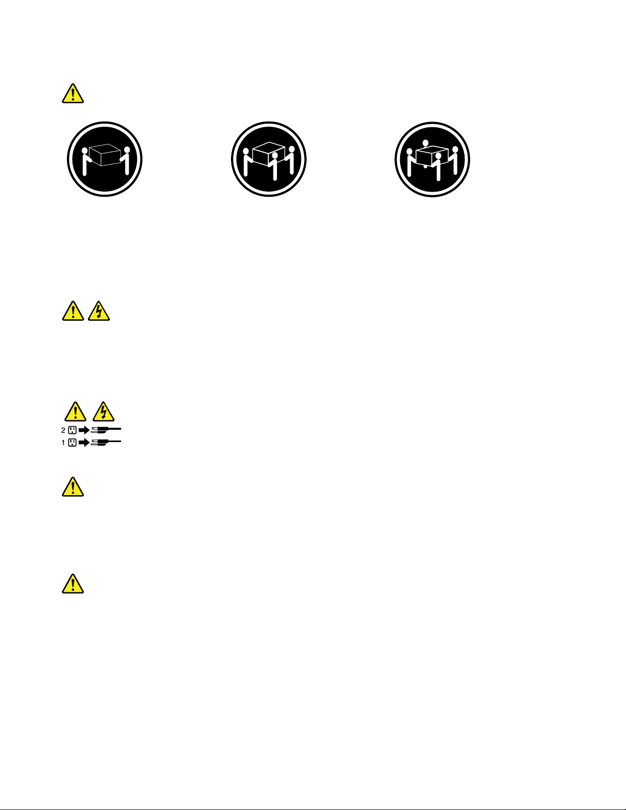
Statement4
≥18kg(39.7lb)≥32kg(70.5lb)≥55kg(121.2lb)
<32kg(70.5lb)<55kg(121.2lb)<100kg(220.5lb)
CAUTION:
Usesafepracticeswhenlifting.
Statement5
CAUTION:
Thepowercontrolbuttononthedeviceandthepowerswitchonthepowersupplydonotturnoff
theelectricalcurrentsuppliedtothedevice.Thedevicealsomighthavemorethanonepower
cord.T oremoveallelectricalcurrentfromthedevice,ensurethatallpowercordsaredisconnected
fromthepowersource.
Statement6
CAUTION:
Ifyouinstallastrain-reliefbracketoptionovertheendofthepowercordthatisconnectedtothe
device,youmustconnecttheotherendofthepowercordtoaneasilyaccessiblepowersource.
Statement7
CAUTION:
Ifthedevicehasdoors,besuretoremoveorsecurethedoorsbeforemovingorliftingthedeviceto
avoidpersonalinjury.Thedoorswillnotsupporttheweightofthedevice.
viThinkServerUserGuide
Page 9
Statement8
CAUTION:
Neverremovethecoveronapowersupplyoranypartthathasthefollowinglabelattached.
Hazardousvoltage,current,andenergylevelsarepresentinsideanycomponentthathasthislabel
attached.Therearenoserviceablepartsinsidethesecomponents.Ifyoususpectaproblemwith
oneoftheseparts,contactaservicetechnician.
Statement9
CAUTION:
Toavoidpersonalinjury,disconnectthehot-swapfancablesbeforeremovingthefanfromthedevice.
Statement10
CAUTION:
Thefollowinglabelindicatessharpedges,corners,orjointsnearby.
Statement11
CAUTION:
Thefollowinglabelindicatesahotsurfacenearby.
Statement12
DANGER
Overloadingabranchcircuitispotentiallyarehazardandashockhazardundercertainconditions.T oavoid
thesehazards,ensurethatyoursystemelectricalrequirementsdonotexceedbranchcircuitprotection
requirements.Refertotheinformationthatisprovidedwithyourdeviceforelectricalspecications.
©CopyrightLenovo2011
vii
Page 10
Statement13
CAUTION:
Makesurethattherackissecuredproperlytoavoidtippingwhentheserverunitisextended.
Statement14
CAUTION:
SomeaccessoryoroptionboardoutputsexceedClass2orlimitedpowersourcelimitsandmustbe
installedwithappropriateinterconnectingcablinginaccordancewiththenationalelectriccode.
Statement15
CAUTION:
Thepower-controlbuttononthedevicedoesnotturnofftheelectricalcurrentsuppliedtothe
device.Thedevicealsomighthavemorethanoneconnectiontodcpower.T oremoveallelectrical
currentfromthedevice,ensurethatallconnectionstodcpoweraredisconnectedatthedcpower
inputterminals.
Statement16
CAUTION:
Toreducetheriskofelectricshockorenergyhazards:
•Thisequipmentmustbeinstalledbytrainedservicepersonnelinarestricted-accesslocation,as
denedbytheNECandthelatesteditionofIEC60950,TheStandardforSafetyofInformation
TechnologyEquipment.
•Connecttheequipmenttoareliablygroundedsafetyextralowvoltage(SELV)source.AnSEL V
sourceisasecondarycircuitthatisdesignedsothatnormalandsinglefaultconditionsdonot
causethevoltagestoexceedasafelevel(60Vdirectcurrent).
•Thebranchcircuitovercurrentprotectionmustberatedinaccordancewithlocalbuildingcodes.
•Use16AmericanWireGauge(AWG)or1.3mm
2
copperconductoronly,notexceeding3meters
inlength.
•T orquethewiring-terminalscrewsto12inch-pounds(1.4newton-meters).
•Incorporateareadilyavailableapprovedandrateddisconnectdeviceintheeldwiring.
Statement17
CAUTION:
ThisproductcontainsaClass1Mlaser.Donotviewdirectlywithopticalinstruments.
viiiThinkServerUserGuide
Page 11
Statement18
CAUTION:
Donotplaceanyobjectontopofrack-mounteddevices.
Statement19
CAUTION:
Hazardousmovingpartsarenearby.
Statement20
CAUTION:
Thebatteryisalithiumionbattery.T oavoidpossibleexplosion,donotburnthebattery.Exchangeit
onlywiththeLenovo-approvedpart.Recycleordiscardthebatteryasinstructedbylocalregulations.
©CopyrightLenovo2011
ix
Page 12

xThinkServerUserGuide
Page 13
Chapter1.Generalinformation
Thischapterprovidessomegeneralinformationaboutyourserver.
Thischaptercontainsthefollowingtopics:
•“Introduction”onpage1
•“Noticesandstatementsinthedocument”onpage1
•“Relateddocumentation”onpage2
Introduction
ThisuserguideisforyourLenovo
®
ThinkServer
Thisdocumentcontainsthefollowinginformation:
•Settingupandcablingtheserver
•Startingandconguringtheserver
•Installingoptionsandreplacingcustomerreplaceableunits(CRUs)
•Solvingproblems
TheservercomeswiththeThinkServerEasyStartupDVDtohelpyoucongurethehardware,installdevice
drivers,andinstalltheoperatingsystem.
®
TS130server(machinetypes1098,1100,1105,and1106).
Theservercomeswithalimitedwarranty.Forinformationaboutthetermsofthewarrantyandgettingservice
andassistance,seetheWarrantyandSupportInformationathttp://www.lenovo.com/support.
Toobtainthemostup-to-dateinformationabouttheserverandotherLenovoproducts,goto:
http://www.lenovo.com/thinkserver
Recordinformationabouttheserverinthefollowingtable.Youwillneedtheseinformationwhenyou
registertheserverwithLenovo.
Productname
Machinetype1098,1100,1105,and1106
Modelnumber
Serialnumber
ThinkServerTS130
_____________________________________________
_____________________________________________
Themodelnumberandserialnumberareonlabelsonthetoporonthebottomoftheserver.
Noticesandstatementsinthedocument
ThecautionanddangerstatementsthatappearinthisdocumentarealsointhemultilingualSafety
Information.Eachcautionanddangerstatementinthisdocumentislabeledwithanumber.Thisnumberis
usedtocrossreferenceanEnglish-languagecautionordangerstatementwithtranslatedversionsofthe
cautionordangerstatementintheSafetyInformation.See“Relateddocumentation”onpage2fordetailed
informationabouthowtogetthevariousdocumentationforyourserver.
Thefollowingnoticesandstatementsareusedinthisdocument:
•Note:Thesenoticesprovideimportanttips,guidance,oradvice.
©CopyrightLenovo2011
1
Page 14

•Important:Thesenoticesprovideinformationoradvicethatmighthelpyouavoidproblemsor
inconvenientsituations.
•Attention:Thesenoticesindicatepotentialdamagetoprograms,devices,ordata.Anattentionnoticeis
placedjustbeforetheinstructionorsituationinwhichdamagecouldoccur.
•Caution:Thesestatementsindicatesituationsthatcanbepotentiallyhazardoustoyou.Acaution
statementisplacedjustbeforethedescriptionofapotentiallyhazardousproceduresteporsituation.
•Danger:Thesestatementsindicatesituationsthatcanbepotentiallylethalorextremelyhazardous
toyou.Adangerstatementisplacedjustbeforethedescriptionofapotentiallylethalorextremely
hazardousproceduresteporsituation.
Relateddocumentation
Toviewthedocumentationathttp://www.lenovo.com/support,youneedtohavetheAdobeReader5.0
programorlaterinstalled.
Thefollowinginformationprovidesgeneraldescriptionsofthevariousdocumentationthatcamewithyour
serverandinformationabouthowtoobtainallthesedocumentation:
•HardwareMaintenanceManual:Thisdocumentprovidesdiagnosticinformation,partslisting,replacement
proceduresforallCRUs,andreplacementproceduresforothereldreplaceableunits(FRUs)replaced
bytrainedservicepersonnel.
•GettingStarted:Thisdocumentprovidesgeneralinformationaboutinstallingandconguringtheserver.
Note:ThisdocumentisinSerbianLatinonly.
•ImportantNotices:Thisdocumentincludessafetyandlegalnoticesthatyouareexpectedtoreadbefore
usingtheserver.
•ReadMeFirst:Thisdocumentdirectsyoutothehttp://www.lenovo.com/supportforcompletewarranty
andsupportinformation.
•SafetyInformation:ThisdocumentincludestranslationsofallsafetystatementsusedintheThinkServer
documentation.
•WarrantyandSupportInformation:Thisdocumentincludesthewarrantystatementandinformation
abouthowtocontactLenovoSupport.
YoucanobtainallthedocumentationinPortableDocumentFormat(PDF)foryourserverfromtheLenovo
SupportWebsiteathttp://www.lenovo.com/support.
2ThinkServerUserGuide
Page 15
Chapter2.Serversetuproadmap
Thischapterprovidesageneralroadmaptoguideyouthroughsettingupyourserver.
Theserversetupprocedurevariesdependingonthecongurationoftheserverwhenitwasdelivered.In
somecases,theserverisfullyconguredandyoujustneedtoconnecttheservertothenetworkandan
electricaloutlet,andthenyoucanturnontheserver.Inothercases,theserverneedstohavehardware
featuresinstalled,requireshardwareandrmwareconguration,andrequirestheoperatingsystemto
beinstalled.
Table1.Serversetuproadmap
TaskWheretondtheinformation
Unpack“Whatisincludedwithyourserver”onpage5
Installhardware
ConnecttheEthernetcable
andpowercord
Turnontheservertoverify
operation
ReviewtheBIOSsettings
andcustomizeasneeded
CongureRAID“ConguringRAID”onpage69
Checkforrmwareupdates
Installtheoperatingsystem
andbasicdrivers
Installanyadditionaldrivers
neededforaddedfeatures
CongureEthernetsettings
intheoperatingsystem
Installapplications
Chapter5“Installing,removing,orreplacinghardware”onpage15
“Rearview”onpage9
“Turningontheserver”onpage49
“StartingtheSetupUtilityprogram”onpage53
“Updatingthermware”onpage71
“EasyStartup”onpage7
Refertotheinstructionsthatcamewiththehardwareoption.
Seetheoperatingsystemhelp.Thisstepisnotrequirediftheoperatingsystemwas
installedusingtheThinkServerEasyStartupprogram.
Refertothedocumentationthatcomeswiththeapplicationsthatyouwanttoinstall.
©CopyrightLenovo2011
3
Page 16

4ThinkServerUserGuide
Page 17
Chapter3.Productoverview
Thischapterprovidesinformationabouttheserverpackage,features,specications,andsoftwareprograms.
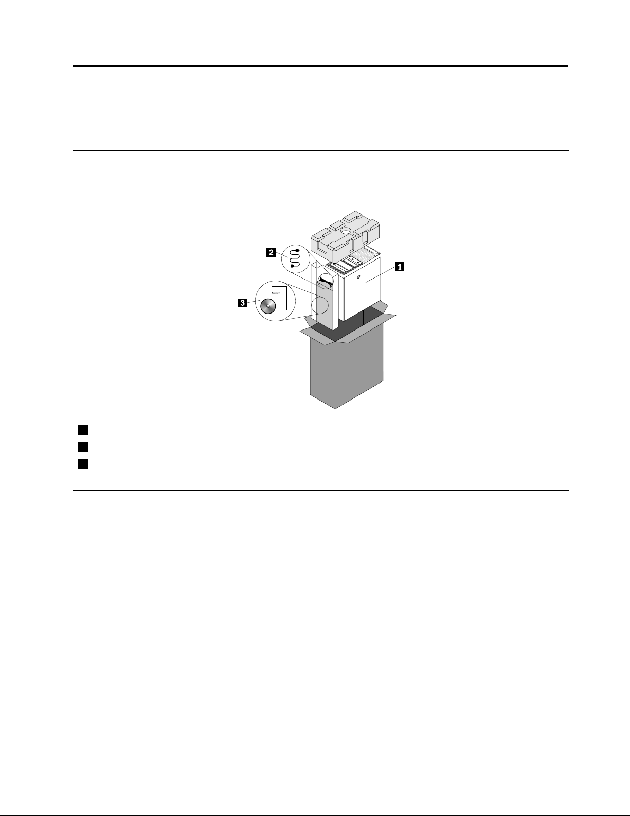
Whatisincludedwithyourserver
TheThinkServerTS130serverpackageincludestheserver,apowercord,documentation,andsoftware
media.
1
Server
2
Powercord
3
Documentationandsoftwaremedia
Featuresandspecications
Thefollowingtableprovidesinformationaboutthefeaturesandspecicationsoftheserver.Depending
ontheservermodel,somefeaturesmightnotbeavailable,orsomespecicationsmightnotapply.For
informationaboutyourspecicmodel,usetheSetupUtilityprogram.See“UsingtheSetupUtilityprogram”
onpage53
.
©CopyrightLenovo2011
5
Page 18
Table2.Featuresandspecications
Microprocessor(s):SupportuptotwoIntel
®
Xeon
dual-core,quad-core,orhex-coremicroprocessors
(internalcachesizevariesbymodeltype)
Forthespecictypeandspeedinformationaboutthe
microprocessor,usetheSetupUtilityprogram.See
“UsingtheSetupUtilityprogram”onpage53
.
Foralistofsupportedmicroprocessors,goto
http://www.lenovo.com/thinkserverandclickOptions
undertheProductstab.
Memory
•SupportsuptofourDDR3ECCUDIMMs(doubledata
rate3errorcorrectioncodeunbuffereddualinline
memorymodules)
•Types:1333MHz,DDR3registeredSDRAMDIMMs
Internaldrives
•SerialAdvancedTechnologyAttachment(SATA)hard
diskdrive
•SATAopticaldrive
Videosubsystem
•IntegratedgraphicsforaVideoGraphicsArray(VGA)
connectorandaDisplayPortconnector
Connectivity
•100/1000MbpsintegratedEthernetcontroller
Powersupply:Yourservercomeswithoneofthe
followingpowersupplies:
•280–wattauto-sensingpowersupply
•320–wattauto-sensingpowersupply
®
Expansion
•Twoopticaldrivebays
•Twoharddiskdrivebays
•TwoPCIcardslots
•OnePCIExpressx1cardslot
•OnePCIExpressx16cardslot
Systemmanagementfeatures
•Abilitytostorepower-onself-test(POST)hardware
testresults
•Automaticpower-onstartup
•IntelActiveManagementT echnology(AMT)
•IntelHyper-Threadingtechnology(somemodels)
•IntelRapidStorageTechnology(RST)
•PrebootExecutionEnvironment(PXE)
•SystemManagement(SM)UEFIandSMsoftware
•WakeonLAN
•WakeonRing(intheSetupUtilityprogram,thisfeature
iscalledSerialPortRingDetectforanexternalmodem)
Input/Output(I/O)features
•EightUniversalSerialBus(USB)connectors(twoon
thefrontpanelandsixontherearpanel)
•One9-pinserialport
•OneEthernetconnector
•OneDisplayPortconnector
•OneVGAmonitorconnector
•Threeaudioconnectorsontherearpanel(audioline-in
connector,audioline-outconnector,andmicrophone
connector)
6ThinkServerUserGuide
Preinstalledoperatingsystem
Somemodelsarepreinstalledwithoneofthefollowing
operatingsystems:
•Microsoft
•MicrosoftWindows
®
WindowsServer
®
®
2008R2Foundation
SmallBusinessServer(SBS)
Aurora
Operatingsystem(s),supported
•MicrosoftWindowsServer2008R2Foundation
•MicrosoftWindowsServer2008R2(ServicePack1)
•MicrosoftWindowsSmallBusinessServer(SBS)
Aurora
•MicrosoftWindowsSmallBusinessServer(SBS)7
•MicrosoftWindowsMultipointServer
Page 19
Table2.Featuresandspecications(continued)
Integratedfunctions:
•Ethernetcontrollers(Theservercomeswithtwo
integratedGigabitEthernetcontrollers,whichsupport
connectionto100Mbpsor1000Mbpsnetwork.)
•Oneserialport
•OneVideoGraphicsArray(VGA)monitorconnector
•SixUSBconnectors(twofrontandfourrear)
•OneRJ-45Ethernetconnectorsontherearpanel
•EightdiagnosticLEDs
Size:
•Width:174.8mm(6.88inches)
•Height:377.3mm(14.85inches)
•Depth:406.7mm(16.01inches)
Weight:Maximumconguration:11.2kg(24.7lbs)
Electricalinput
•Inputvoltage:
–Lowrange:
Minimum:90Vac
Maximum:137Vac
–Highrange:
Minimum:180Vac
Maximum:264Vac
Environment
•Airtemperature:
Operating:10°Cto35°C(50°Fto95°F)
Non-operating:-40°Cto60°C(14°Fto140°F)(with
package)
Non-operating:-10°Cto60°C(14°Fto140°F)
(withoutpackage)
•Humidity:
Operating:10%to80%(non-condensing)(10%
perhour)
Non-operating:10%to90%(non-condensing)
(10%perhour)
•Altitude:
Operating:-50to10000ft(-15.2to3048m)
Non-operating:-50to35000ft(-15.2to10668m)
Securityfeatures
•Computrace
•Enablingordisablingadevice
•EnablingordisablingUSBconnectorsindividually
•Harddiskdrivepassword
•Power-OnPassword(POP)andAdministrator
PasswordforUEFIaccess
•Startupsequencecontrol
•Startupwithoutkeyboardormouse
•Supportforanintegratedcablelock(Kensingtonlock)
•Supportforapadlock
•TrustedPlatformModule(TPM)
Softwareprograms
Lenovoprovidessoftwaretohelpgetyourserverupandrunning.
EasyStartup
TheThinkServerEasyStartupprogramsimpliestheprocessofconguringRAIDandinstallingsupported
MicrosoftWindowsoperatingsystemsanddevicedriversonyourserver.TheEasyStartupprogramis
providedwithyourserverontheThinkServerEasyStartupDVD.TheDVDisself-starting(bootable).Theuser
guidefortheEasyStartupprogramisontheDVDandcanbeaccesseddirectlyfromtheprograminterface.
Foradditionalinformation,see“UsingtheThinkServerEasyStartupprogram”onpage72
.
Reliability,availability,andserviceability
Reliability,availability,andserviceability(hereafterreferredtoasRAS)arethreeimportantserverdesign
features.TheRASfeatureshelpyoutoensuretheintegrityofthedatastoredontheserver,theavailabilityof
theserverwhenyouneedit,andtheeasewithwhichyoucandiagnoseandcorrectproblems.
TheserverhasthefollowingRASfeatures:
Chapter3.Productoverview7
Page 20

•AdvancedCongurationandPowerInterface(ACPI)
•AdvancedDesktopManagementInterface(DMI)
•Automaticmemorydownsizingonerrordetection
•Automaticrestartonnon-maskableinterrupt(NMI)
•Availabilityofmicrocodelevel
•Built-in,menu-drivensetup,systemconguration,andRAIDconguration
•Built-inmonitoringforfan,temperature,andvoltage
•Coolingfanswithspeed-sensingcapability
•ECCDDR3SDRAMwithSerialPresenceDetect(SPD)
•Errorcodesandmessagestohelpyouidentifyproblems
•Generatingerrorlogsforthepower-onself-test(POST)failures
•Hot-swapSASharddiskdrives
•IntegratedEthernetcontrollers
•IntelligentPlatformManagementInterface(IPMI)2.0
•Power-onself-test(POST)
•Standbyvoltageforsystem-managementfeaturesandmonitoring
•System-errorlight-emittingdiode(LED)onthefrontpanel
•Vitalproductdata(VPD),includingtheserialnumberinformationandreplacementpartnumbers,storedin
thenonvolatilememoryforeasierremotemaintenance
8ThinkServerUserGuide
Page 21
Chapter4.Locatingparts,controls,andconnectors
Thischapterprovidesinformationtohelpyoulocateyourserverparts,controls,andconnectors.
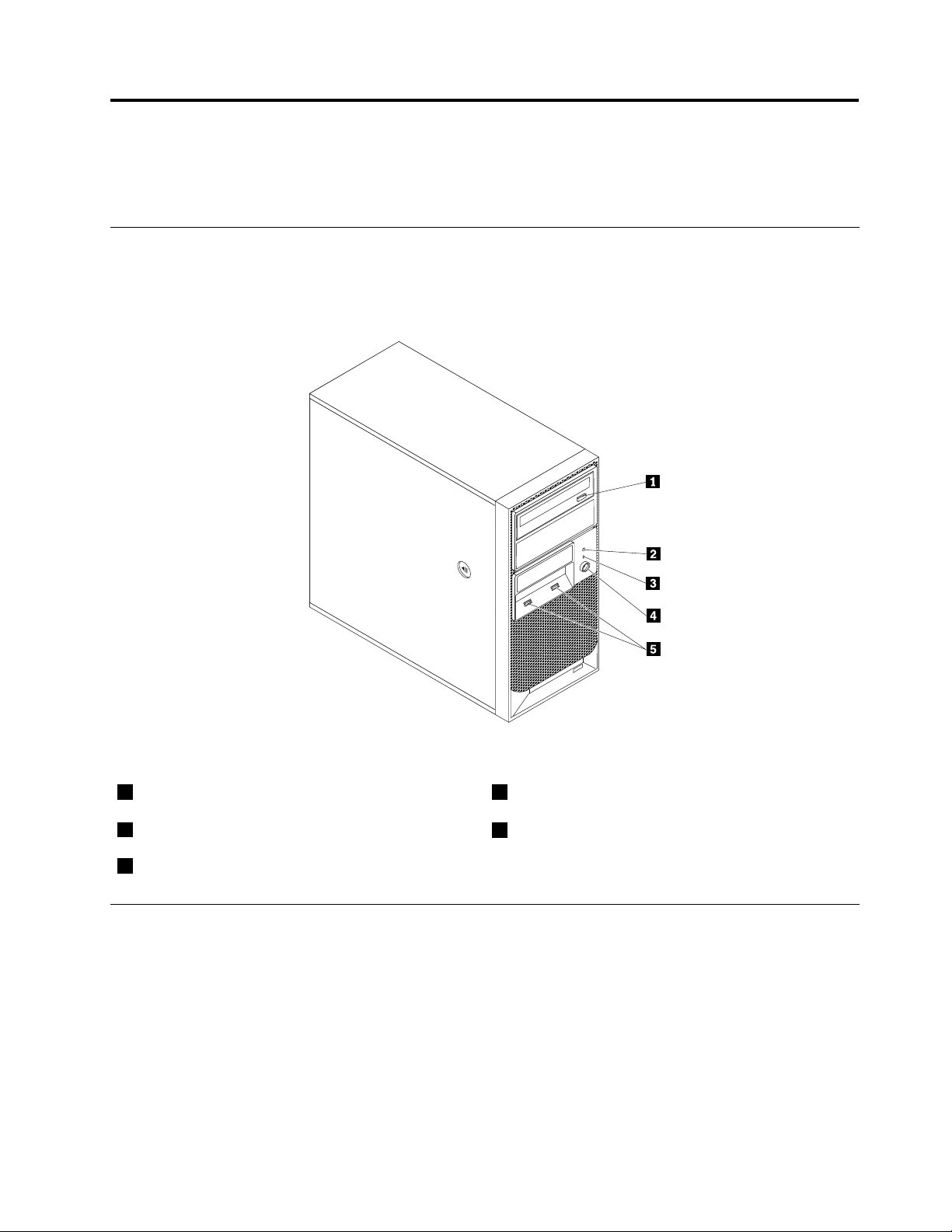
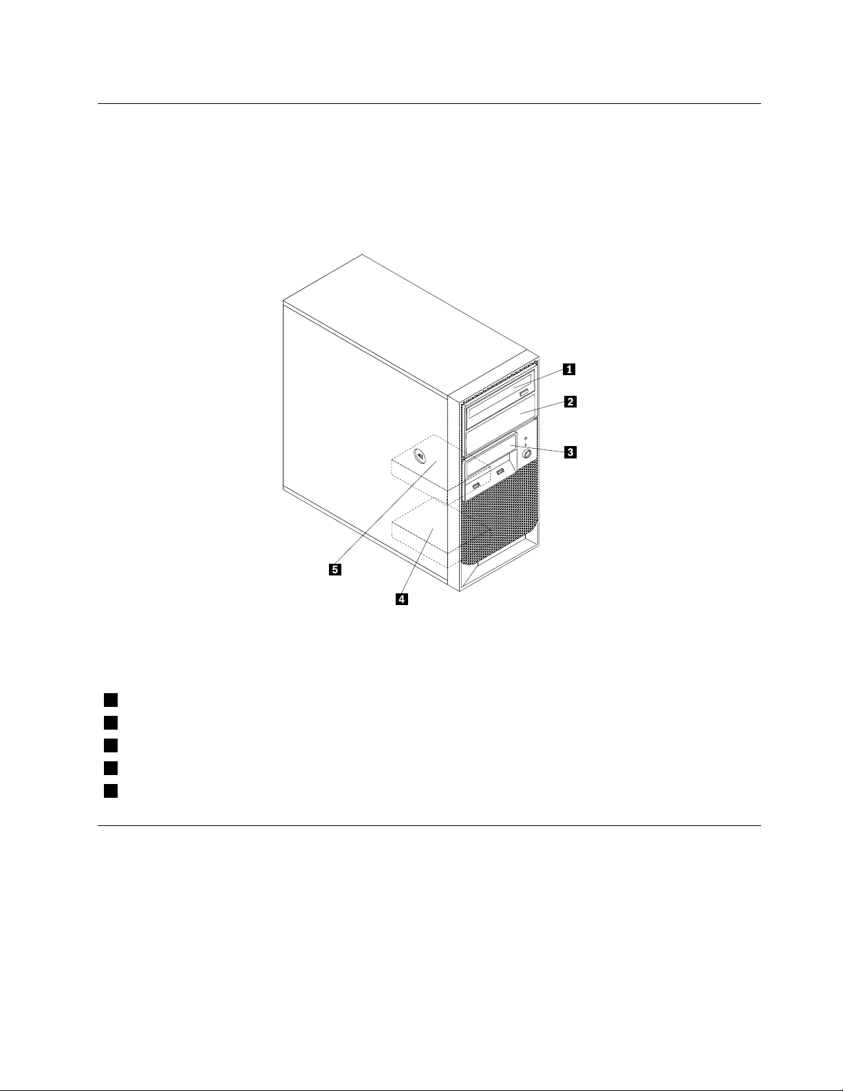
Frontview
Figure1“Frontcontrolandconnectorlocations”onpage9showsthelocationsofthecontrolsand
connectorsonthefrontofyourserver.
Figure1.Frontcontrolandconnectorlocations
1Opticaldriveeject/closebutton
2HarddiskdriveactivityLED
3Power-onLED
4Powerswitch
5USBconnectors(2)
Rearview
Figure2“Rearconnectorlocations”onpage10showsthelocationsoftheconnectorsontherearof
yourserver.Someconnectorsontherearofyourserverarecolor-codedtohelpyoudeterminewhereto
connectthecablesinyourserver.
©CopyrightLenovo2011
9
Page 22
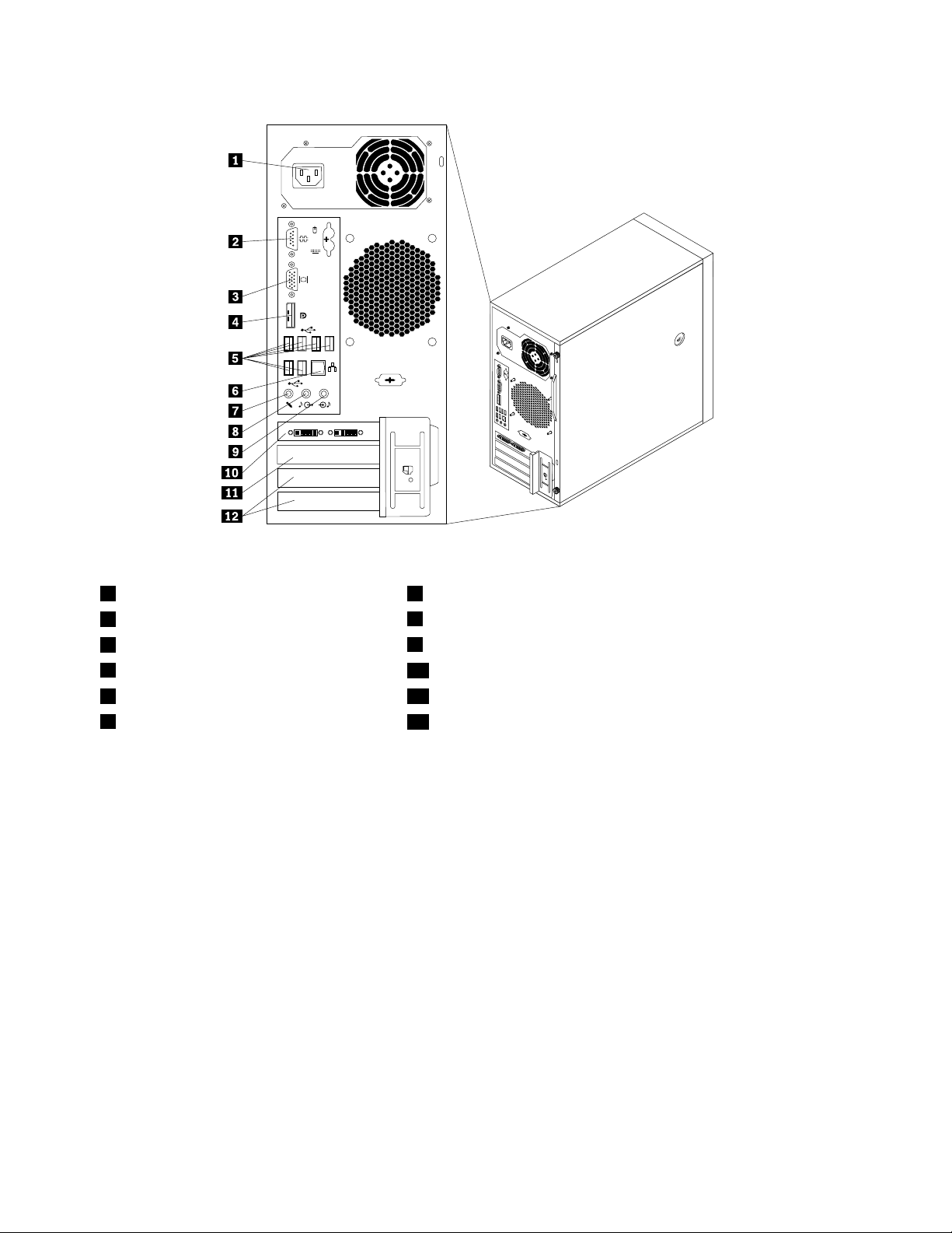
Figure2.Rearconnectorlocations
1Powercordconnector7Microphoneconnector
2Serialport
3VGAmonitorconnector
4DisplayPortconnector
5USBconnectors(6)11PCIExpressx1cardslot
6Ethernetconnector
8Audioline-outconnector
9Audioline-inconnector
10PCIExpressx16cardslot
12PCIcardslots(2)
ConnectorDescription
Audioline-inconnector
Usedtoreceiveaudiosignalsfromanexternalaudiodevice,suchasastereo
system.Whenyouattachanexternalaudiodevice,acableconnectstheaudio
line-outconnectorofthedevicetotheaudioline-inconnectoroftheserver.
Audioline-outconnector
Usedtosendaudiosignalsfromtheservertoexternaldevices,suchaspowered
stereospeakers(speakerswithbuilt-inampliers),headphones,multimedia
keyboards,ortheaudioline-inconnectoronastereosystemorotherexternal
recordingdevice.
DisplayPortconnector
Usedtoattachahigh-performancemonitor,adirect-drivemonitor,orotherdevices
thatuseaDisplayPortconnector.
Ethernetconnector
UsedtoattachanEthernetcableforalocalareanetwork(LAN).
Note:T ooperatetheserverwithinFCCClassBlimits,useaCategory5Ethernet
cable.
Microphoneconnector
Usedtoattachamicrophonetoyourserverwhenyouwanttorecordsoundorif
youusespeech-recognitionsoftware.
Serialport
Usedtoattachanexternalmodem,aserialprinter,orotherdevicesthatusea
9-pinserialport.
10ThinkServerUserGuide
Page 23
ConnectorDescription
USBconnectorUsedtoattachadevicethatrequiresaUSBconnector,suchasaUSBkeyboard,a
USBmouse,aUSBscanner,oraUSBprinter.IfyouhavemorethaneightUSB
devices,youcanpurchaseaUSBhub,whichyoucanusetoconnectadditional
USBdevices.
VGAmonitorconnectorUsedtoattachaVGAmonitororotherdevicesthatuseaVGAmonitorconnector.
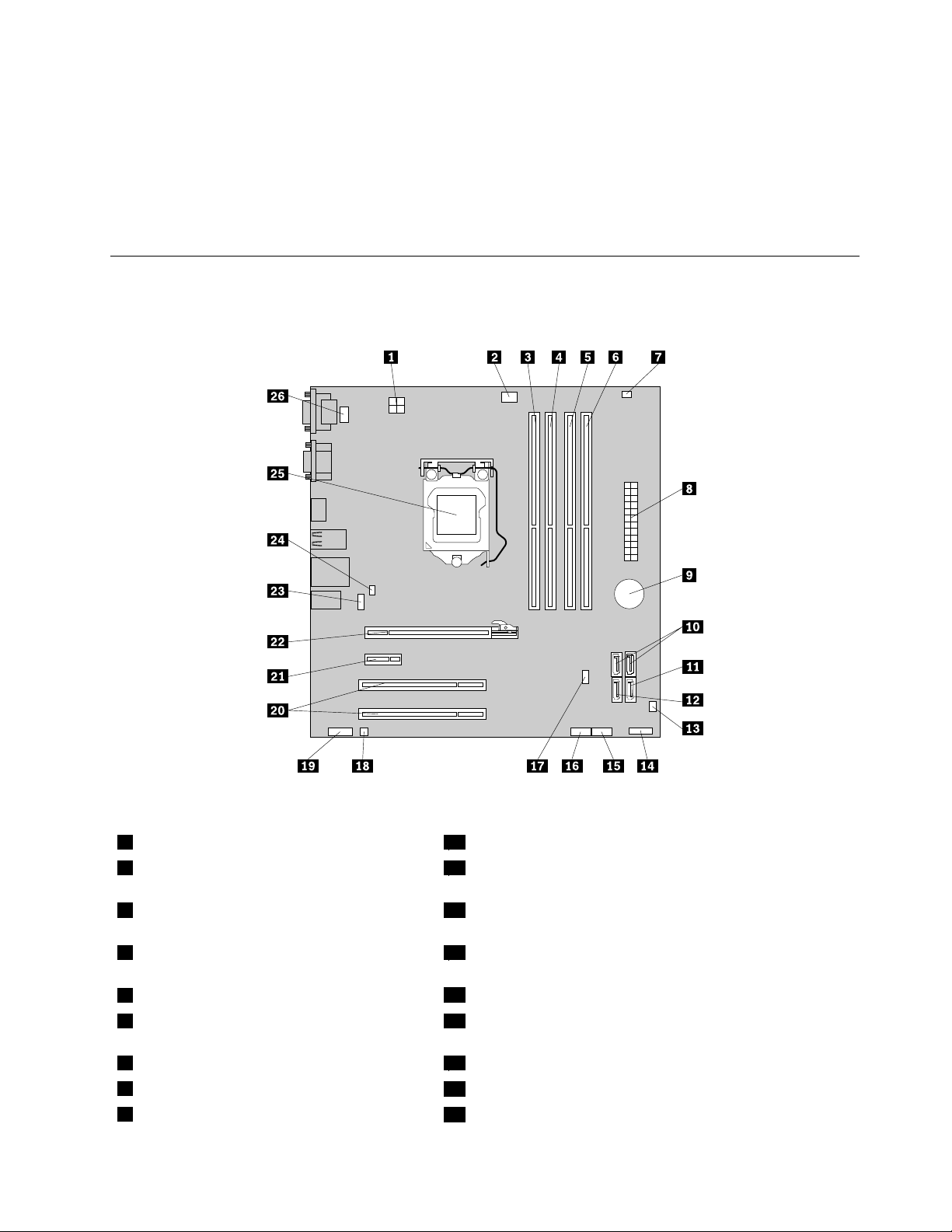
Locatingpartsonthesystemboard
Figure3“Systemboardpartlocations”onpage11showsthelocationsofthepartsonthesystemboard.
Figure3.Systemboardpartlocations
14-pinpowerconnector
2Microprocessorfanconnector
14FrontpanelconnectorforpowerswitchandLEDindicators
15FrontUSBconnector1(forconnectingUSBport1and2
onthefrontbezel)
3Memoryslot1(DIMM1)16FrontUSBconnector2(forconnectingadditionalUSB
devices)
4Memoryslot2(DIMM2)17ClearCMOS(ComplementaryMetalOxideSemiconductor)
/Recoveryjumper
5Memoryslot3(DIMM3)
6Memoryslot4(DIMM4)19Frontaudioconnector(forconnectingthemicrophoneand
18Internalspeakerconnector
headphoneconnectorsonthefrontbezel)
7Thermalsensorconnector
824-pinpowerconnector
9Battery
20PCIcardslots(2)
21PCIExpressx1cardslot
22PCIExpressx16graphicscardslot
Chapter4.Locatingparts,controls,andconnectors11
Page 24
10SATAconnectors1and2(SATA3.0
23Rearfanconnector
connectors)
11SATAconnector3(SATA2.0connector)24Coverpresenceswitchconnector(Intrusionswitchconnector)
12eSATAconnector
13Frontfanconnector
25Microprocessor
26PS/2keyboardandmouseconnector
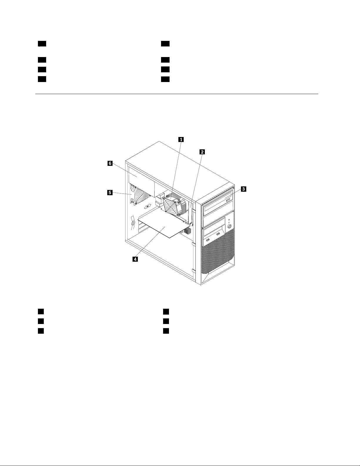
Internalcomponents
Figure4“Componentlocations”onpage12showsthelocationsofthevariouscomponentsinyourserver.
Toremovetheservercoverandaccesstheinsideoftheserver,see“Removingtheservercover”onpage17
.
Figure4.Componentlocations
1Heatsinkandfanassembly
2Memorymodule
3Opticaldrive
12ThinkServerUserGuide
4PCIcard
5Rearfanassembly
6Powersupplyassembly
Page 25
Internaldrives
Internaldrivesaredevicesthatyourserverusestoreadandstoredata.Y oucanadddrivestoyourserverto
increasestoragecapacityandenableyourservertoreadothertypesofmedia.Internaldrivesareinstalledin
bays.Inthismanual,thebaysarereferredtoasbay1,bay2,andsoon.
Figure5“Drivebaylocations”onpage13showsthelocationsofthedrivebays.
Figure5.Drivebaylocations
Thefollowinglistdescribesthetypeandsizeofthedrivethatyoucaninstallineachbay:
1Bay1-Opticaldrivebay(withanopticaldriveinstalledonsomemodels)
2Bay2-Opticaldrivebay
3Bay3-Cardreaderdrivebay
4Bay4-SecondarySATAharddiskdrivebay
5Bay5-PrimarySATAharddiskdrivebay(witha3.5-inchSATAharddiskdriveinstalled)
Machinetypeandmodellabel
Themachinetypeandmodellabelidentiesyourcomputer.WhenyoucontactLenovoforhelp,themachine
typeandmodelinformationhelpssupporttechnicianstoidentifyyourcomputerandprovidefasterservice.
Chapter4.Locatingparts,controls,andconnectors13
Page 26
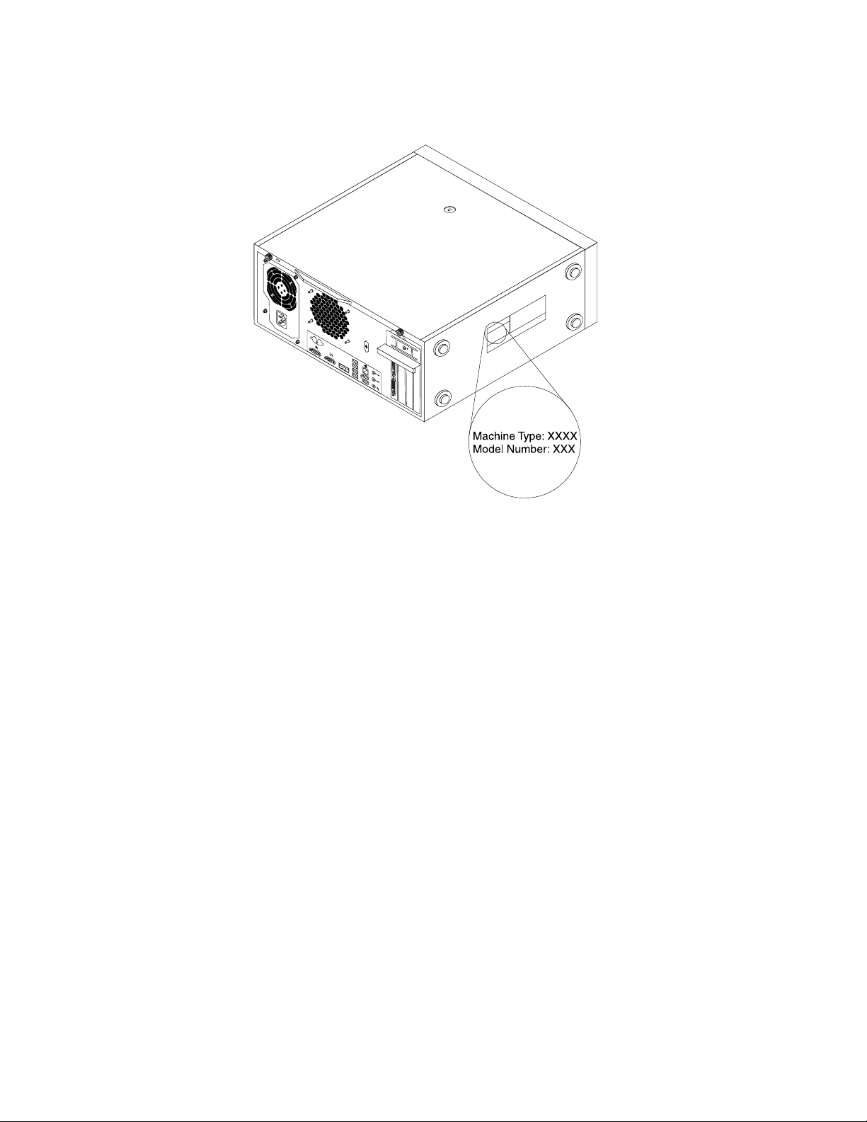
Thefollowingisasampleofthemachinetypeandmodellabel.
Figure6.Machinetypeandmodellabel
14ThinkServerUserGuide
Page 27

Chapter5.Installing,removing,orreplacinghardware
Thischapterprovidesinstructionsonhowtoinstall,remove,orreplacehardwareforyourserver.
Thischaptercontainsthefollowingtopics:
•“Guidelines”onpage15
•“Removingtheservercover”onpage17
•“Removingandreinstallingthefrontbezel”onpage18
•“Installing,removing,orreplacingoptionalhardwaredevices”onpage20
•“Installing,removing,orreplacinghardwaredevices”onpage34
•“Completingthepartsreplacement”onpage48
•“Installingsecurityfeatures”onpage51
Guidelines
Thissectionprovidessomeguidelinesthatyoushouldreadandunderstandbeforeusingyourserver.
Basicguidelines
Beforeyouusetheserver,besuretoreadandunderstandthefollowingguidelines:
•BesuretoreadandunderstandtheSafetyInformationandtheWarrantyandSupportInformationat
http://www.lenovo.com/support,and“Guidelines”onpage15.Theinformationwillhelpyouworksafely.
•Whenyouinstallyournewserver,taketheopportunitytodownloadandapplythemostrecentrmware
updates.Thisstepwillhelptoensurethatanyknownissuesareaddressedandthatyourserveris
readytofunctionatmaximumlevelsofperformance.T odownloadrmwareupdatesforyourserver,
dothefollowing:
1.Gotohttp://www.lenovo.com/support.
2.ClickDownload&Drivers➙ThinkServerandthenfollowtheinstructionsontheWebpageto
downloadrmwareupdatesforyourserver.
•Beforeyouinstalloptionalhardwaredevices,makesurethattheserverisworkingcorrectly.Ifan
operatingsystemisinstalled,turnontheserverandmakesurethattheoperatingsystemstarts.Ifno
operatingsystemisinstalled,makesurethatamessageBOOTMGRismissingisdisplayed,indicatingthatan
operatingsystemwasnotfoundbuttheserverisworkingcorrectly.Iftheserverisnotworkingcorrectly,
refertoChapter7“Troubleshootinganddiagnostics”onpage75
•Observegoodhousekeepingintheareawhereyouareworking.Putremovedcoversandotherparts
inasafeplace.
•Ifyoumustturnontheserverwhiletheservercoverisremoved,makesurethatnooneisneartheserver
andthatnotoolsorotherobjectshavebeenleftinsidetheserver.
•Donotattempttoliftanobjectthatyouthinkistooheavyforyou.Ifyouhavetoliftaheavyobject,
observethefollowingprecautions:
fordetaileddiagnosticinformation.
–Makesurethatyoucanstandsafelywithoutslipping.
–Distributetheweightoftheobjectequallybetweenyourfeet.
–Useaslowliftingforce.Nevermovesuddenlyortwistwhenyouliftaheavyobject.
–Toavoidstrainingthemusclesinyourback,liftbystandingorbypushingupwithyourlegmuscles.
©CopyrightLenovo2011
15
Page 28
•Makesurethatyouhaveanadequatenumberofproperlygroundedelectricaloutletsfortheserver,
monitor,andotherdevices.
•Backupallimportantdatabeforeyoumakechangestodrives.
•Haveasmallat-bladescrewdriveravailable.
•ToviewtheerrorLEDsonthesystemboardandinternalcomponents,leavetheserverconnectedto
power.
•Youdonothavetoturnofftheservertoinstallorreplacehot-swapfans,redundanthot-swapacpower
supplies,orhot-plugUSBdevices.However,youmustturnofftheserverbeforeperforminganystepsthat
involveinstalling,removing,orreplacingadaptercablesornon-hot-swapoptionaldevicesorcomponents.
•Aftercompletinganyinstallation,removal,orreplacementprocedure,reinstallallsafetyshields,guards,
labels,andgroundwires.
•Foralistofsupportedoptionaldevicesfortheserver,gotohttp://www.lenovo.com/thinkserver.
•Whenworkinginsidetheserver,youmightndsometaskseasierifyoulaytheserveronitsside.Y ou
mightneedtorstpivotthefootstandsinwardandthenlaythecomputeronitsside.
Systemreliabilityguidelines
Tohelpensurepropercoolingandsystemreliability,makesurethatyoufollowtheseguidelines:
•EverydrivebayhasaninternaldriveinstalledoranElectroMagneticCompatibility(EMC)shieldinstalled.
•Iftheserverhasredundantpower,everypowersupplybayhasapowersupplyassemblyinstalled.
•Leaveadequatespacearoundtheservertomakesurethattheservercoolingsystemworkswell.
•Properlyroutethecables.Forsomeoptions,suchasPCIcards,followthecablinginstructionsthat
comewiththeoptions.
•Makesurethatyoureplaceafailingfanwithin48hours.
•Whenreplacingahot-swapdrive,installthenewhot-swapdrivewithintwominutesofremoval.
•Donotremoveanyairductorairbafeswhiletheserverisrunning.Operatingtheserverwithoutthe
airductorairbafesmightcausethemicroprocessortooverheat.
•Thesecondmicroprocessorsocketalwayscontainseitheramicroprocessorsocketcoverora
microprocessorandheatsinkassembly.
Handlingstatic-sensitivedevices
Attention:
Donotopenthestatic-protectivepackagecontainingthenewpartuntilthedefectiveparthasbeenremovedfromthe
serverandyouarereadytoinstallthenewpart.Staticelectricity,althoughharmlesstoyou,canseriouslydamage
servercomponentsandparts.
Whenyouhandleserverpartsandcomponents,taketheseprecautionstoavoidstatic-electricitydamage:
•Limityourmovement.Movementcancausestaticelectricitytobuilduparoundyou.
•Wearanelectrostatic-dischargewriststrap,ifoneisavailable.
•Alwayscarefullyhandlethepartsandothercomponents(suchasPCIcards,memorymodules,system
boards,andmicroprocessors)byitsedgesoritsframe.Donottouchsolderjoints,pins,orexposed
circuitry.
•Preventothersfromtouchingthepartsandothercomputercomponents.
•Beforeyoureplaceanewpart,touchthestatic-protectivepackagecontainingthenewparttoametal
expansion-slotcoverorotherunpaintedmetalsurfaceontheserverforatleasttwoseconds.This
reducesstaticelectricityfromthepackageandyourbody.
16ThinkServerUserGuide
Page 29
•Removethenewpartfromthestatic-protectivepackageanddirectlyinstallitintheserverwithout
placingitonanyothersurface.Ifitishardforyoutodothisinyourspecicsituation,placethe
static-protectivepackageofthenewpartonasmooth,levelsurface,andthenplacethenewparton
thestatic-protectivepackage.
•Donotplacethepartontheservercoverorothermetalsurface.
•Takeadditionalcarewhenhandlingdevicesduringcoldweather.Heatingreducesindoorhumidity
andincreasesstaticelectricity.
Removingtheservercover
Attention:
DonotopenyourserverorattemptanyrepairbeforereadingandunderstandingtheSafetyInformationandthe
WarrantyandSupportInformationontheThinkServerDocumentationDVDthatcamewithyourproduct,and
“Guidelines”onpage15
http://www.lenovo.com/support
Thissectionprovidesinstructionsonhowtoremovetheservercover.
CAUTION:
Turnofftheserverandwaitthreetoveminutestolettheservercoolbeforeremovingtheserver
cover.
.Toobtainacopyofthepublications,goto:
Toremovetheservercover,dothefollowing:
1.Removeanymediafromthedrivesandturnoffallattacheddevicesandtheserver.
2.Disconnectallpowercordsfromelectricaloutlets.
3.Disconnectthepowercords,Input/Output(I/O)cables,andanyothercablesthatareconnectedtothe
server.See“Frontview”onpage9and“Rearview”onpage9.
4.Removeanylockingdevicethatsecurestheservercover,suchasapadlockoranintegratedcablelock.
See“Integratedcablelock”onpage51and“Padlock”onpage51.
5.Removethetwothumbscrewsthatsecuretheservercover.
Chapter5.Installing,removing,orreplacinghardware17
Page 30
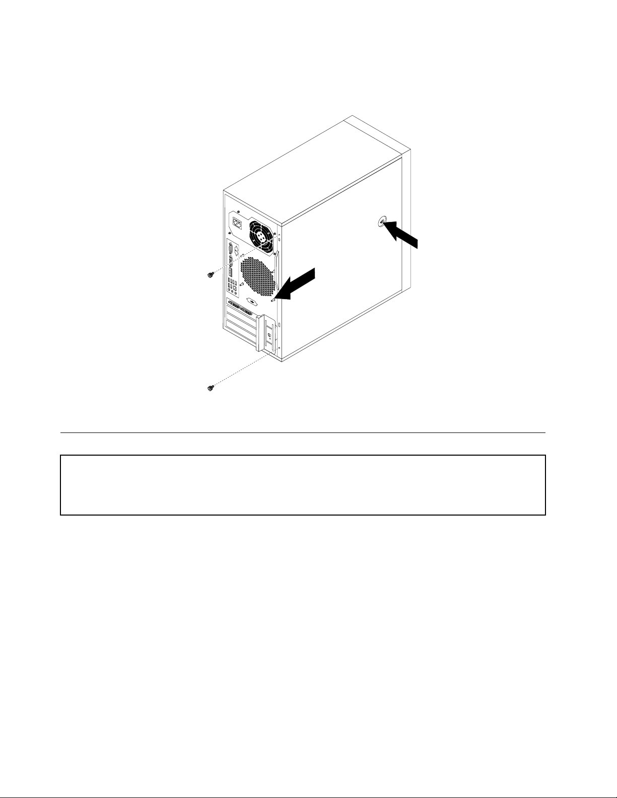
6.Pressthecover-releasebuttononthesideoftheserverandslidethecovertotherearoftheserver
toremovethecover.
Figure7.Removingtheservercover
Removingandreinstallingthefrontbezel
Attention:
DonotopenyourserverorattemptanyrepairbeforereadingandunderstandingtheSafetyInformationandthe
WarrantyandSupportInformationontheThinkServerDocumentationDVDthatcamewithyourproduct,and
“Guidelines”onpage15
http://www.lenovo.com/support
Thissectionprovidesinstructionsonhowtoremoveandreinstallthefrontbezel.
Toremoveandreinstallthefrontbezel,dothefollowing:
1.Removeallmediafromthedrivesandturnoffallattacheddevicesandtheserver.Then,disconnectall
powercordsfromelectricaloutletsanddisconnectallcablesthatareconnectedtotheserver.
2.Removetheservercover.See“Removingtheservercover”onpage17.
.Toobtainacopyofthepublications,goto:
18ThinkServerUserGuide
Page 31

3.Removethefrontbezelbyreleasingthethreeplastictabsontheleftsideandpivotingthefrontbezel
outward.
Figure8.Removingthefrontbezel
4.Toreinstallthefrontbezel,alignthethreeplastictabsontherightsideofthefrontbezelwiththe
correspondingholesinthechassis,thenpivotthefrontbezelinwarduntilitsnapsintopositionon
theleftside.
Figure9.Reinstallingthefrontbezel
Chapter5.Installing,removing,orreplacinghardware19
Page 32

Whattodonext:
•Toworkwithanotherpieceofhardware,gototheappropriatesection.
•Tocompletetheinstallationorreplacement,goto“Completingthepartsreplacement”onpage48.
Installing,removing,orreplacingoptionalhardwaredevices
Thissectionprovidesinstructionsonhowtoinstall,remove,orreplaceoptionalhardwaredevicesforyour
server.Youcanexpandthecapabilitiesofyourserverbyaddingmemorymodules,PCIcards,ordrives,
andmaintainyourserverbyreplacingthefailingoptionalhardwaredevices.Ifyouarereplacinganoptional
hardwaredevice,performtheremovalprocedureandthenperformtheinstallationprocedurefortheoptional
hardwaredevicethatyouwanttoreplace.
InstallingorreplacingaPCIcard
Attention:
DonotopenyourserverorattemptanyrepairbeforereadingandunderstandingtheSafetyInformationandthe
WarrantyandSupportInformationontheThinkServerDocumentationDVDthatcamewithyourproduct,and
“Guidelines”onpage15.Toobtainacopyofthepublications,goto:
http://www.lenovo.com/support
ThissectionprovidesinstructionsonhowtoinstallorreplaceaPCIcard.
YourserverhastwostandardPCIcardslots,onePCIExpressx1cardslot,andonePCIExpressx16
cardslot.
ToinstallorreplaceaPCIcard,dothefollowing:
1.Removeallmediafromthedrivesandturnoffallattacheddevicesandtheserver.Then,disconnectall
powercordsfromelectricaloutletsanddisconnectallcablesthatareconnectedtotheserver.
2.Removetheservercover.See“Removingtheservercover”onpage17.
20ThinkServerUserGuide
Page 33

3.Attherearoftheserver,pressthereleasebutton1toopenthePCIcardlatch2.
Figure10.OpeningthePCIcardlatch
Chapter5.Installing,removing,orreplacinghardware21
Page 34

4.IfyouareinstallingaPCIcard,removetheappropriatemetalslotcover.IfyouarereplacinganoldPCI
card,grasptheoldcardthatiscurrentlyinstalledandgentlypullitoutoftheslot.
Notes:
a.ThePCIcardtstightlyintothecardslot.Ifnecessary,alternatemovingeachsideofthecarda
smallandequalamountuntilitiscompletelyremovedfromthecardslot.
b.IfthePCIcardisheldinplacebyaretaininglatch,pressthecardretaininglatch1asshownto
disengagethelatch.GraspthePCIcardandgentlypullitoutofthecardslot.
Figure11.RemovingaPCIcard
5.RemovethenewPCIcardfromitsstatic-protectivepackage.
6.InstallthenewPCIcardintotheappropriateslotonthesystemboard.See“Locatingpartsonthe
systemboard”onpage11.
Note:IfyouareinstallingaPCIExpressx16card,makesurethememoryslotretainingclipsareclosed
beforeyouinstallthePCIExpressx16card.
22ThinkServerUserGuide
Page 35

7.PivotthePCIcardlatchtotheclosedpositiontosecurethePCIcard.
Figure12.InstallingaPCIcard
Whattodonext:
•Toworkwithanotherpieceofhardware,gototheappropriatesection.
•Tocompletetheinstallationorreplacement,goto“Completingthepartsreplacement”onpage48.
InstallingorremovingtheEthernetcard
Attention:
DonotopenyourserverorattemptanyrepairbeforereadingandunderstandingtheSafetyInformationandthe
WarrantyandSupportInformationontheThinkServerDocumentationDVDthatcamewithyourproduct,and
“Guidelines”onpage15.Toobtainacopyofthepublications,goto:
http://www.lenovo.com/support
ThissectionprovidesinstructionsonhowtoinstallorremovetheEthernetcard.Useanydocumentationthat
camewiththeEthernetcardandfollowthoseinstructionsinadditiontotheinstructionsinthissection.
ToinstallorremovetheEthernetcard,dothefollowing:
1.Removeallmediafromthedrivesandturnoffallattacheddevicesandtheserver.Then,disconnectall
powercordsfromelectricaloutletsanddisconnectallcablesthatareconnectedtotheserver.
2.Removetheservercover.See“Removingtheservercover”onpage17.
3.Laytheserveronitssideforeasieroperation.
4.TheEthernetcardisakindofPCIcard.See“InstallingorreplacingaPCIcard”onpage20andfollow
thoseinstructionstoinstallorremovetheEthernetcard.
5.IfyouareinstructedtoreturntheremovedEthernetcardtothemanufacturer,followallpackaging
instructionsanduseanypackagingmaterialsthataresuppliedtoyouforshipping.
Chapter5.Installing,removing,orreplacinghardware23
Page 36

IfyouareusingtheMicrosoftWindowsoperatingsystems,youneedtoinstallthedevicedriverforthe
Ethernetcard.ToinstallthedevicedriveronWindowsoperatingsystems,dothefollowing:
1.Saveanyopendocumentsandexitallapplications.
2.InserttheThinkServerEasyStartupDVDthatcamewithyourserverintotheDVDdrive.
Note:YoudonotneedtousethedriverdiscthatcamewiththeEthernetcard.
3.Right-clickMyComputerandselectProperties.TheSystemPropertieswindowopens.
4.OntheHardwaretab,clicktheDeviceManagerbutton.TheDeviceManagerwindowopens.
5.ExpandNetworkadaptersandthenright-clickoneoftheEthernetcards(PRO/1000PTortheyellow
questionmark).
6.SelectUpdateDriver....TheHardwareUpdateWizardprogramopens.
7.SelectInstallthesoftwareautomatically(Recommended)andclickNexttocontinue.
8.Followtheinstructionsonthescreen.
Whattodonext:
•Toworkwithanotherpieceofhardware,gototheappropriatesection.
•Tocompletetheinstallation,goto“Completingthepartsreplacement”onpage48.
Installingorremovingamemorymodule
Attention:
DonotopenyourserverorattemptanyrepairbeforereadingandunderstandingtheSafetyInformationandthe
WarrantyandSupportInformationontheThinkServerDocumentationDVDthatcamewithyourproduct,and
“Guidelines”onpage15.Toobtainacopyofthepublications,goto:
http://www.lenovo.com/support
Thissectionprovidesinstructionsonhowtoinstallorremoveamemorymodule.
YourserverhasfourslotsforinstallingorreplacingDDR3UDIMMsthatprovideuptoamaximumof16GB
systemmemory.Wheninstallingorreplacingamemorymodule,usethefollowingguidelines:
•Use1GB,2GB,or4GBDDR3UDIMMsinanycombinationuptoamaximumof16GB.
•InstallmemorymodulesinthesequenceofDIMM1,DIMM3,DIMM2,andDIMM4.See“Locating
partsonthesystemboard”onpage11
.
Toinstallorreplaceamemorymodule,dothefollowing:
1.Removeallmediafromthedrivesandturnoffallattacheddevicesandtheserver.Then,disconnectall
powercordsfromelectricaloutletsanddisconnectallcablesthatareconnectedtotheserver.
2.Removetheservercover.See“Removingtheservercover”onpage17.
3.Laytheserveronitssideforeasieraccesstothesystemboard.
4.Locatethememoryslots.See“Locatingpartsonthesystemboard”onpage11.
5.Removeanypartsthatmightpreventyouraccesstothememoryslots.Dependingonyourserver
model,youmightneedtoremovethePCIExpressx16graphicscardforeasieraccesstothememory
slots.See“InstallingorreplacingaPCIcard”onpage20.
6.Dependingonwhetheryouareinstallingorreplacingamemorymodule,dooneofthefollowing:
24ThinkServerUserGuide
Page 37

•Ifyouarereplacinganoldmemorymodule,opentheretainingclipsandgentlypullthememory
moduleoutofthememoryslot.
Figure13.Removingamemorymodule
•Ifyouareinstallinganewmemorymodule,opentheretainingclipsofthememoryslotintowhichyou
wanttoinstallthememorymodule.
Figure14.Openingtheretainingclips
7.Touchthestatic-protectivepackagethatcontainsthenewmemorymoduletoanyunpaintedmetal
surfaceontheoutsideoftheserver.Then,removethenewmemorymodulefromthepackage.
Chapter5.Installing,removing,orreplacinghardware25
Page 38

8.Positionthenewmemorymoduleoverthememoryslot.Makesurethatthenotch1onthenewmemory
moduleisalignedwiththekey2inthememoryslot.Then,pressthenewmemorymodulestraightdown
intothememoryslotuntiltheretainingclipscloseandthenewmemorymodulesnapsintoposition.
Note:Ifthereisagapbetweenthememorymoduleandtheretainingclips,thememorymodulehas
notbeencorrectlyinstalled.Opentheretainingclips,removethememorymodule,andthenreinstallit
intotheslot.
Figure15.Installingamemorymodule
9.ReinstallthePCIExpressx16graphicscardifyouhaveremovedit.
Whattodonext:
•Toworkwithanotherpieceofhardware,gototheappropriatesection.
•Tocompletetheinstallationorreplacement,goto“Completingthepartsreplacement”onpage48.
Installingorreplacingtheopticaldrive
Attention:
DonotopenyourserverorattemptanyrepairbeforereadingandunderstandingtheSafetyInformationandthe
WarrantyandSupportInformationontheThinkServerDocumentationDVDthatcamewithyourproduct,and
“Guidelines”onpage15
http://www.lenovo.com/support
Thissectionprovidesinstructionsonhowtoinstallorreplacetheopticaldrive.
Toinstallorreplaceanopticaldrive,dothefollowing:
1.Removeallmediafromthedrivesandturnoffallattacheddevicesandtheserver.Then,disconnectall
powercordsfromelectricaloutletsanddisconnectallcablesthatareconnectedtotheserver.
2.Removetheservercover.See“Removingtheservercover”onpage17.
3.Removethefrontbezel.See“Removingandreinstallingthefrontbezel”onpage18.
4.Dependingonwhetheryouareinstallingorreplacinganopticaldrive,dooneofthefollowing:
•Ifyouareinstallingasecondaryopticaldrive,removetheplasticpanelinthefrontbezelforthe
drivebayyouwanttouse.Ifthereisametalstaticshieldinstalledinthedrivebay,removethe
metalstaticshield.
.Toobtainacopyofthepublications,goto:
26ThinkServerUserGuide
Page 39

•Ifyouarereplacinganopticaldrive,disconnectthesignalcableandthepowercablefromtherear
oftheopticaldrive,pressthebluereleasebuttonandthenslidetheopticaldriveoutofthefrontof
theserver.
Figure16.Removingtheopticaldrive
5.Slidethenewopticaldrivewiththeopticaldriveretainer1installedintothedrivebayfromthefrontof
theserveruntiltheopticaldrivesnapsintoposition.
Figure17.Installingtheopticaldrive
Chapter5.Installing,removing,orreplacinghardware27
Page 40

6.Reinstallthefrontbezel.See“Removingandreinstallingthefrontbezel”onpage18.
7.ConnectoneendofthesignalcabletotheopticaldriveandtheotherendtoanavailableSATA
connectoronthesystemboard.See“Locatingpartsonthesystemboard”onpage11.Then,locatean
availableve-wirepowerconnectorandconnectittotheSATAdrive.
Figure18.ConnectingaSATAopticaldrive
Whattodonext:
•Toworkwithanotherpieceofhardware,gototheappropriatesection.
•Tocompletetheinstallationorreplacement,goto“Completingthepartsreplacement”onpage48.
Replacingtheprimaryharddiskdrive
Attention:
DonotopenyourserverorattemptanyrepairbeforereadingandunderstandingtheSafetyInformationandthe
WarrantyandSupportInformationontheThinkServerDocumentationDVDthatcamewithyourproduct,and
“Guidelines”onpage15.Toobtainacopyofthepublications,goto:
http://www.lenovo.com/support
Thissectionprovidesinstructionsonhowtoreplacetheprimaryharddiskdrive.
Toreplacetheprimaryharddiskdrive,dothefollowing:
1.Removeallmediafromthedrivesandturnoffallattacheddevicesandtheserver.Then,disconnectall
powercordsfromelectricaloutletsanddisconnectallcablesthatareconnectedtotheserver.
2.Removetheservercover.See“Removingtheservercover”onpage17.
3.Locatetheprimaryharddiskdrive.See“Locatingpartsonthesystemboard”onpage11.
4.Disconnectthesignalcableandthepowercablefromtherearoftheharddiskdrive.
28ThinkServerUserGuide
Page 41

5.Pressthebluereleasetab1downward,slidetheharddiskdrivecage2totherearoftheserver,and
thenpivotitoutwardtocompletelyremovethedrivecagefromthechassis.Then,pullontheblue
handle3toremovetheharddiskdrivefromthedrivecage.
Figure19.Removingtheprimaryharddiskdrive
6.Flexthesidesofthebluebrackettoremovetheharddiskdrivefromthebracket.
7.Toinstallanewharddiskdriveintothebluebracket,exthesidesofthebracketandalignpin1,pin2,
pin3,andpin4onthebracketwiththecorrespondingholesintheharddiskdrive.Donottouchthe
circuitboard5onthebottomoftheharddiskdrive.
Note:Ifyouareinstallinga2.5-inchharddiskdrive,installtheharddiskdriveintoa2.5-inchto3.5-inch
harddiskdrivetrayrstandtheninstallthetrayintothebluebracket.
Figure20.Installingtheharddiskdriveintothebracket
Chapter5.Installing,removing,orreplacinghardware29
Page 42

8.Slidethenewharddiskdrivewiththebluebracketintothedrivecageuntilitsnapsintopositionand
aligntheharddiskdrivecagepivotpinwiththeslot1intheupperdrivecage.Then,slidetheharddisk
drivecageintothechassis.Pressdownonthemetallatch2andpivottheharddiskdrivecageinto
place.Then,slidethedrivecagetothefrontoftheserveruntilitsnapsintoposition.
Note:Therearetwoarrows,oneontheupperdrivecageandoneontheharddiskdrivecage.The
arrowsarealignedwhentheharddiskdriveisinthecorrectposition.
Figure21.Installingtheprimaryharddiskdrive
30ThinkServerUserGuide
Page 43

9.ConnectoneendofthesignalcabletotheharddiskdriveandtheotherendtoanavailableSATA
connectoronthesystemboard.See“Locatingpartsonthesystemboard”onpage11.Then,locatean
availableve-wirepowerconnectorandconnectittotheharddiskdrive.
Figure22.ConnectingaSATAharddiskdrive
Whattodonext:
•Toworkwithanotherpieceofhardware,gototheappropriatesection.
•Tocompletethereplacement,goto“Completingthepartsreplacement”onpage48.
Installingorreplacingthesecondaryharddiskdrive
Attention:
DonotopenyourserverorattemptanyrepairbeforereadingandunderstandingtheSafetyInformationandthe
WarrantyandSupportInformationontheThinkServerDocumentationDVDthatcamewithyourproduct,and
“Guidelines”onpage15
http://www.lenovo.com/support
.Toobtainacopyofthepublications,goto:
Toinstallorreplacethesecondaryharddiskdrive,dothefollowing:
1.Removeallmediafromthedrivesandturnoffallattacheddevicesandtheserver.Then,disconnectall
powercordsfromelectricaloutletsanddisconnectallcablesthatareconnectedtotheserver.
2.Removetheservercover.See“Removingtheservercover”onpage17.
3.Locatethesecondaryharddiskdrive.See“Locatingpartsonthesystemboard”onpage11and
“Internaldrives”onpage13.
4.Ifyouarereplacingthesecondaryharddiskdrive,disconnectthesignalcableandthepowercable
fromtheharddiskdrive.
Chapter5.Installing,removing,orreplacinghardware31
Page 44

5.Pressthereleasebutton1toreleasetheharddiskdrivecageandthenlifttheharddiskdrivecage
outofthechassis.
Figure23.Removingthesecondaryharddiskdrive
6.Pullonthebluehandletoreleaseandremovetheharddiskdrivefromtheharddiskdrivecage.
7.Flexthesidesofthebluebrackettoremovetheharddiskdrivefromthebracket.
8.Toinstallthesecondaryharddiskdrive,exthesidesofthebracketproperlyandalignpin1,pin2,pin
3,andpin4onthebracketwiththecorrespondingholesintheharddiskdrive.Donottouchthecircuit
board5onthebottomoftheharddiskdrive.
Note:Ifyouareinstallinga2.5-inchharddiskdrive,installtheharddiskdriveintoa2.5-inchto3.5-inch
harddiskdrivetrayrstandtheninstallthetrayintothebluebracket.
Figure24.Installingtheharddiskdriveintothebracket
32ThinkServerUserGuide
Page 45

9.Slidethenewharddiskdrivewiththebluebracketintothesecondaryharddiskdrivecageuntil
itsnapsintoposition.
10.Slidetheharddiskdrivecagewiththenewharddiskdriveintothechassisuntilitisdirectlyunderneath
themetaltab1.
Figure25.Installingthesecondaryharddiskdrive
Chapter5.Installing,removing,orreplacinghardware33
Page 46

11.Presstheharddiskdrivecagedownwarduntilitsnapsintoposition.Makesurethattheharddisk
drivecageissecuredinthechassis.
Figure26.Installingthesecondaryharddiskdrive
12.ConnectoneendofthesignalcabletotheharddiskdriveandtheotherendtoanavailableSATA
connectoronthesystemboard.See“Locatingpartsonthesystemboard”onpage11.Then,locatean
availableve-wirepowerconnectorandconnectittotheharddiskdrive.
Figure27.ConnectingaSATAharddiskdrive
Installing,removing,orreplacinghardwaredevices
Thissectionprovidesinstructionsonhowtoinstall,remove,orreplacehardwaredevicesforyourserver.
Youcanmaintainyourserverbyreplacingthefailinghardwaredevices.Ifyouarereplacingahardware
device,performtheremovalprocedureandthenperformtheinstallationprocedureforthehardwaredevice
thatyouwanttoreplace.
34ThinkServerUserGuide
Page 47

Replacingthepowersupplyassembly
Attention:
DonotopenyourserverorattemptanyrepairbeforereadingandunderstandingtheSafetyInformationandthe
WarrantyandSupportInformationontheThinkServerDocumentationDVDthatcamewithyourproduct,and
“Guidelines”onpage15
http://www.lenovo.com/support
Thissectionprovidesinstructionsonhowtoreplacethepowersupplyassembly.
Althoughtherearenomovingpartsinyourserverafterthepowercordhasbeendisconnected,thefollowing
warningsarerequiredforyoursafetyandproperUnderwritersLaboratories(UL)certication.
DANGER
Hazardousmovingparts.Keepngersandotherbodypartsaway.
.Toobtainacopyofthepublications,goto:
CAUTION:
Neverremovethecoveronapowersupplyoranypartthathasthefollowinglabelattached.
Hazardousvoltage,current,andenergylevelsarepresentinsideanycomponentthathasthislabel
attached.Therearenoserviceablepartsinsidethesecomponents.Ifyoususpectaproblemwith
oneoftheseparts,contactaservicetechnician.
Toreplacethepowersupplyassembly,dothefollowing:
1.Removeallmediafromthedrivesandturnoffallattacheddevicesandtheserver.Then,disconnectall
powercordsfromelectricaloutletsanddisconnectallcablesthatareconnectedtotheserver.
2.Removetheservercover.See“Removingtheservercover”onpage17.
3.Laytheserveronitssideanddisconnectthepowersupplyassemblycablesfromthesystemboardand
alldrives.See“Locatingpartsonthesystemboard”onpage11.
Chapter5.Installing,removing,orreplacinghardware35
Page 48

4.Removethefourscrewsattherearofthechassisthatsecurethepowersupplyassembly.
Figure28.Removingthescrewsthatsecurethepowersupplyassembly
5.Slidethepowersupplyassemblyalittlebitforwardandthenremoveitfromthechassis.
Figure29.Removingthepowersupplyassembly
6.Ensurethatthenewpowersupplyassemblyisthecorrectreplacement.
7.Installthenewpowersupplyassemblyintothechassissothatthescrewholesinthepowersupply
assemblyalignwiththoseinthechassis.
8.Installandtightenthefourscrewstosecurethepowersupplyassembly.
Note:UseonlyscrewsprovidedbyLenovo.
9.Reconnectthepowersupplyassemblycablestothesystemboardandeachofthedrives.
10.Securethepowersupplyassemblycableswiththecableclipsandtiesinthechassis.
36ThinkServerUserGuide
Page 49

Whattodonext:
•Toworkwithanotherpieceofhardware,gototheappropriatesection.
•Tocompletethereplacement,goto“Completingthepartsreplacement”onpage48.
Replacingtheheatsinkandfanassembly
Attention:
DonotopenyourserverorattemptanyrepairbeforereadingandunderstandingtheSafetyInformationandthe
WarrantyandSupportInformationontheThinkServerDocumentationDVDthatcamewithyourproduct,and
“Guidelines”onpage15
http://www.lenovo.com/support
Thissectionprovidesinstructionsonhowtoreplacetheheatsinkandfanassembly.
CAUTION:
Turnofftheserverandwaitthreetoveminutestolettheservercoolbeforeremovingtheserver
cover.
Toreplacetheheatsinkandfanassembly,dothefollowing:
1.Removeallmediafromthedrivesandturnoffallattacheddevicesandtheserver.Then,disconnectall
powercordsfromelectricaloutletsanddisconnectallcablesthatareconnectedtotheserver.
2.Removetheservercover.See“Removingtheservercover”onpage17.
3.Laytheserveronitssideforeasieraccesstothesystemboard.
4.Locatetheheatsinkandfanassembly.See“Locatingpartsonthesystemboard”onpage11.
5.Disconnecttheheatsinkandfanassemblycablefromthemicroprocessorfanconnectoronthesystem
board.See“Locatingpartsonthesystemboard”onpage11.
.Toobtainacopyofthepublications,goto:
Chapter5.Installing,removing,orreplacinghardware37
Page 50

6.Followthissequencetoremovethefourscrewsthatsecuretheheatsinkandfanassemblytothe
systemboard:
a.Partiallyremovescrew1,thenfullyremovescrew2,andthenfullyremovescrew1.
b.Partiallyremovescrew3,thenfullyremovescrew4,andthenfullyremovescrew3.
Note:Carefullyremovethefourscrewsfromthesystemboardtoavoidanypossibledamagetothe
systemboard.Thefourscrewscannotberemovedfromtheheatsinkandfanassembly.
Figure30.Removingtheheatsinkandfanassembly
7.Liftthefailingheatsinkandfanassemblyoffthesystemboard.
Notes:
a.Youmighthavetogentlytwisttheheatsinkandfanassemblytofreeitfromthemicroprocessor.
b.Whilehandlingtheheatsinkandfanassembly,donottouchthethermalgreaseonthebottomofit.
8.Placethenewheatsinkandfanassemblyonthesystemboardsothatthefourscrewsontheheatsink
andfanassemblyarealignedwiththecorrespondingholesonthesystemboard.Makesurethatyou
properlyplacetheheatsinkandfanassemblysothatyoucaneasilyconnecttheheatsinkandfan
assemblycabletothemicroprocessorfanconnectoronthesystemboard.
9.Followthissequencetoinstallthefourscrewstosecurethenewheatsinkandfanassembly.SeeFigure
30“Removingtheheatsinkandfanassembly”onpage38
.
a.Partiallytightenscrew1,thenfullytightenscrew2,andthenfullytightenscrew1.
b.Partiallytightenscrew3,thenfullytightenscrew4,andthenfullytightenscrew3.
Note:Donotover-tightenthescrews.
10.Connecttheheatsinkandfanassemblycabletothemicroprocessorfanconnectoronthesystem
board.See“Locatingpartsonthesystemboard”onpage11.
Whattodonext:
•Toworkwithanotherpieceofhardware,gototheappropriatesection.
38ThinkServerUserGuide
Page 51

•Tocompletethereplacement,goto“Completingthepartsreplacement”onpage48.
ReplacingthefrontaudioandUSBassembly
Attention:
DonotopenyourserverorattemptanyrepairbeforereadingandunderstandingtheSafetyInformationandthe
WarrantyandSupportInformationontheThinkServerDocumentationDVDthatcamewithyourproduct,and
“Guidelines”onpage15
http://www.lenovo.com/support
ThissectionprovidesinstructionsonhowtoreplacethefrontaudioandUSBassembly.
ToreplacethefrontaudioandUSBassembly,dothefollowing:
1.Removeallmediafromthedrivesandturnoffallattacheddevicesandtheserver.Then,disconnectall
powercordsfromelectricaloutletsanddisconnectallcablesthatareconnectedtotheserver.
2.Removetheservercover.See“Removingtheservercover”onpage17.
3.Removethefrontbezel.See“Removingandreinstallingthefrontbezel”onpage18.
4.DisconnectthefrontaudioandUSBassemblycablefromthesystemboard.SeeChapter4“Locating
parts,controls,andconnectors”onpage9.
5.NotethefrontaudioandUSBassemblycableroutingandremovethescrewthatsecuresthefrontaudio
andUSBassembly.Then,removethefrontaudioandUSBassemblyfromthechassis.
.Toobtainacopyofthepublications,goto:
Figure31.RemovingthefrontaudioandUSBassembly
6.RoutethenewfrontaudioandUSBassemblythroughtheholeinthechassis.
7.PositionthenewfrontaudioandUSBassemblytothechassissothatthescrewholeinthenewfront
audioandUSBassemblyisalignedwiththecorrespondingholeinthechassis.
8.InstallthescrewtosecurethenewfrontaudioandUSBassemblyinplace.
9.ConnectthenewfrontaudioandUSBassemblycablestothesystemboard.SeeChapter4“Locating
parts,controls,andconnectors”onpage9.
Chapter5.Installing,removing,orreplacinghardware39
Page 52

10.Reinstallthefrontbezel.See“Removingandreinstallingthefrontbezel”onpage18.
Whattodonext:
•Toworkwithanotherpieceofhardware,gototheappropriatesection.
•Tocompletethereplacement,goto“Completingthepartsreplacement”onpage48.
Replacingthefrontfanassembly
Attention:
DonotopenyourserverorattemptanyrepairbeforereadingandunderstandingtheSafetyInformationandthe
WarrantyandSupportInformationontheThinkServerDocumentationDVDthatcamewithyourproduct,and
“Guidelines”onpage15
http://www.lenovo.com/support
Dependingonthemodeltype,yourservermighthaveafrontfanassemblyinstalled.Thissectionprovides
instructionsonhowtoreplacethefrontfanassembly.
Toreplacethefrontfanassembly,dothefollowing:
1.Removeallmediafromthedrivesandturnoffallattacheddevicesandtheserver.Then,disconnectall
powercordsfromelectricaloutletsanddisconnectallcablesthatareconnectedtotheserver.
2.Removetheservercover.See“Removingtheservercover”onpage17.
3.Removethefrontbezel.See“Removingandreinstallingthefrontbezel”onpage18.
4.Disconnectthefrontfanassemblycablefromthepowerfanconnectoronthesystemboard.See
“Locatingpartsonthesystemboard”onpage11
.Toobtainacopyofthepublications,goto:
.
Note:Ifyourserverhasasecondaryharddiskdriveinstalled,removethesecondaryharddiskdrive
togeteasieraccesstothepowerfanconnectoronthesystemboard.See“Installingorreplacingthe
secondaryharddiskdrive”onpage31.
40ThinkServerUserGuide
Page 53

5.Releasethetwotabs1thatattachthefrontfanassemblytothechassisasshownandthencompletely
removethefrontfanassemblyfromthechassis.
Figure32.Removingthefrontfanassembly
Chapter5.Installing,removing,orreplacinghardware41
Page 54

6.Insertthetwotabs2ofthenewfrontfanassemblyintothecorrespondingholesinthechassis,and
presstheothertwotabs1throughtheholesuntilthefrontfanassemblyissecuredinplace.
Figure33.Installingthefrontfanassembly
7.Connectthenewfrontfanassemblycabletothepowerfanconnectoronthesystemboard.See
“Locatingpartsonthesystemboard”onpage11
.
Whattodonext:
•Toworkwithanotherpieceofhardware,gototheappropriatesection.
•Tocompletethereplacement,goto“Completingthepartsreplacement”onpage48.
Replacingtherearfanassembly
Attention:
DonotopenyourserverorattemptanyrepairbeforereadingandunderstandingtheSafetyInformationandthe
WarrantyandSupportInformationontheThinkServerDocumentationDVDthatcamewithyourproduct,and
“Guidelines”onpage15
http://www.lenovo.com/support
Thissectionprovidesinstructionsonhowtoreplacetherearfanassembly.
Toreplacetherearfanassembly,dothefollowing:
1.Removeallmediafromthedrivesandturnoffallattacheddevicesandtheserver.Then,disconnectall
powercordsfromelectricaloutletsanddisconnectallcablesthatareconnectedtotheserver.
.Toobtainacopyofthepublications,goto:
42ThinkServerUserGuide
Page 55

2.Removetheservercover.See“Removingtheservercover”onpage17.
3.Locatetherearfanassembly.See“Internalcomponents”onpage12.
4.Disconnecttherearfanassemblycablefromthesystemfanconnectoronthesystemboard.See
“Locatingpartsonthesystemboard”onpage11.
5.Therearfanassemblyisattachedtothechassisbyfourrubbermounts.Removetherearfanassembly
bycuttingtherubbermountsandgentlypullingtherearfanassemblyoutofthechassis.
Figure34.Removingtherearfanassembly
6.Installthenewrearfanassemblybyaligningthenewrubbermountswiththecorrespondingholesinthe
chassisandpushtherubbermountsthroughtheholes.
Note:Thenewrearfanassemblywillhavefournewrubbermountsattached.
Chapter5.Installing,removing,orreplacinghardware43
Page 56

7.Carefullypullonthetipsoftherubbermountsuntilthenewrearfanassemblyissecuredinplace.
Figure35.Installingtherearfanassembly
8.Connectthenewrearfanassemblycabletothesystemfanconnectoronthesystemboard.See
“Locatingpartsonthesystemboard”onpage11.
Whattodonext:
•Toworkwithanotherpieceofhardware,gototheappropriatesection.
•Tocompletethereplacement,goto“Completingthepartsreplacement”onpage48.
Replacingthemicroprocessor
Attention:
DonotopenyourserverorattemptanyrepairbeforereadingandunderstandingtheSafetyInformationandthe
WarrantyandSupportInformationontheThinkServerDocumentationDVDthatcamewithyourproduct,and
“Guidelines”onpage15
http://www.lenovo.com/support
Thissectionprovidesinstructionsonhowtoreplacethemicroprocessor.
CAUTION:
Theheatsinkandmicroprocessormightbeveryhot.T urnoffthecomputerandwaitthreetove
minutestoletthecomputercoolbeforeremovingthecomputercover .
.Toobtainacopyofthepublications,goto:
44ThinkServerUserGuide
Page 57

Toreplacethemicroprocessor,dothefollowing:
1.Removeallmediafromthedrivesandturnoffallattacheddevicesandthecomputer.Then,disconnect
allpowercordsfromelectricaloutletsanddisconnectallcablesthatareconnectedtothecomputer.
2.Removethecomputercover.See“Removingtheservercover”onpage17.
3.Laythecomputeronitssideforeasieraccesstothesystemboard.
4.Locatethesystemboardanddisconnectallcablesconnectedtothesystemboard.See“Locating
partsonthesystemboard”onpage11
.
5.Removetheheatsinkandfanassembly.See“Replacingtheheatsinkandfanassembly”onpage37.
Note:Placetheheatsinkandfanassemblyonitssidesothatthethermalgreaseonthebottomofit
doesnotgetincontactwithanything.
6.Liftthesmallhandle1andopentheretainer2toaccessthemicroprocessor3.
Figure36.Accessingthemicroprocessor
7.Liftthemicroprocessorstraightupandoutofthemicroprocessorsocket.
Figure37.Removingthemicroprocessor
Chapter5.Installing,removing,orreplacinghardware45
Page 58

Notes:
a.Yourmicroprocessorandsocketmightlookdifferentfromtheoneillustrated.
b.Notetheorientationofthemicroprocessorinthesocket.Y oucaneitherlookforthesmalltriangle1
ononecornerofthemicroprocessorornotetheorientationofthenotches2onthemicroprocessor.
Thisisimportantwheninstallingthenewmicroprocessoronthesystemboard.
c.Touchonlytheedgesofthemicroprocessor.Donottouchthegoldcontactsonthebottom.
d.Donotdropanythingontothemicroprocessorsocketwhileitisexposed.Thesocketpinsmustbe
keptascleanaspossible.
8.Makesurethatthesmallhandleisintheraisedpositionandthemicroprocessorretainerisfullyopen.
9.Removetheprotectivecoverthatprotectsthegoldcontactsofthenewmicroprocessor.
10.Holdthenewmicroprocessorbyitssidesandalignthesmalltriangleononecornerofthenew
microprocessorwiththecorrespondingsmalltriangleononecornerofthemicroprocessorsocket.
11.Lowerthenewmicroprocessorstraightdownintothemicroprocessorsocketonthesystemboard.
Figure38.Installingthemicroprocessor
12.Closethemicroprocessorretainerandlockitintopositionwiththesmallhandletosecurethenew
microprocessorinthesocket.
13.Reinstalltheheatsinkandfanassembly.See“Replacingtheheatsinkandfanassembly”onpage37.
46ThinkServerUserGuide
Page 59

14.Reconnectallcablesthatweredisconnectedfromthesystemboard.
Whattodonext:
•Toworkwithanotherpieceofhardware,gototheappropriatesection.
•Tocompletethereplacement,goto“Completingthepartsreplacement”onpage48.
Replacingthesystemboardbattery
Attention:
DonotopenyourserverorattemptanyrepairbeforereadingandunderstandingtheSafetyInformationandthe
WarrantyandSupportInformationontheThinkServerDocumentationDVDthatcamewithyourproduct,and
“Guidelines”onpage15
http://www.lenovo.com/support
Thissectionprovidesinstructionsonhowtoreplacethesystemboardbattery.
Yourserverhasaspecialtypeofmemorythatmaintainsthedate,time,andcongurationinformationfor
built-infeatures.Thesystemboardbatterykeepsthisinformationactivewhenyouturnofftheserver.
Thesystemboardbatterynormallyrequiresnochargingormaintenancethroughoutitslife;however,no
batterylastsforever.Ifthesystemboardbatteryfails,thedate,time,andcongurationinformation,including
passwords,arelost.Anerrormessageisdisplayedwhenyouturnontheserver.
Besuretoconsiderthefollowinginformationwhenyoureplacethebatteryintheserver:
.Toobtainacopyofthepublications,goto:
•Youmustreplacethebatterywithalithiumbatteryofthesametypefromthesamemanufacturer.
•Toavoidpossibledanger,besuretoreadandunderstandthefollowingsafetystatement.
•Afteryoureplacethesystemboardbattery,youmustresetpasswords,systemdateandtime,and
reconguretheserver.
Statement2
CAUTION:
Whenreplacingthelithiumbattery,useonlythebatteryrecommendedbythemanufacturer.Ifyour
systemhasamodulecontainingalithiumbattery,replaceitonlywiththesamemoduletypemadeby
thesamemanufacturer.Thebatterycontainslithiumandcanexplodeifnotproperlyused,handled,
ordisposedof.
Donot:
•Throworimmerseintowater
•Heattomorethan100°C(212°F)
•Repairordisassemble
Disposeofthebatteryasrequiredbylocalordinancesorregulations.
Toreplacethesystemboardbattery,dothefollowing:
1.Removeallmediafromthedrivesandturnoffallattacheddevicesandtheserver.Then,disconnectall
powercordsfromelectricaloutletsanddisconnectallcablesthatareconnectedtotheserver.
2.Removetheservercover.See“Removingtheservercover”onpage17.
3.Locatethesystemboardbattery.SeeChapter4“Locatingparts,controls,andconnectors”onpage9.
Chapter5.Installing,removing,orreplacinghardware47
Page 60

4.Removetheoldsystemboardbattery.
Figure39.Removingtheoldsystemboardbattery
5.Installthenewsystemboardbattery.
Figure40.Installingthenewsystemboardbattery
6.Reinstallthecomputercoverandconnectthecables.See“Completingthepartsreplacement”on
page48
.
Note:Whenthecomputeristurnedonforthersttimeafterthebatteryisreplaced,anerrormessage
mightbedisplayed.Thisisnormalafterreplacingthebattery.
7.Turnonthecomputerandallattacheddevices.
8.UsetheSetupUtilityprogramtosetthedate,time,andanypasswords.SeeChapter6“Conguring
theserver”onpage53.
9.Disposeofthefailingbatteryasrequiredbylocalordinancesorregulations.
Whattodonext:
•Toworkwithanotherpieceofhardware,gototheappropriatesection.
•Tocompletethereplacement,goto“Completingthepartsreplacement”onpage48.
Completingthepartsreplacement
Aftercompletingtheinstallationorreplacementforallparts,youneedtoreinstalltheservercoverand
reconnectcables.
Toreinstalltheservercoverandreconnectcablestoyourserver,dothefollowing:
1.Makesurethatallcomponentshavebeenreassembledcorrectlyandthatnotoolsorloosescrewsare
leftinsideyourserver.See“Internalcomponents”onpage12forthelocationsofvariouscomponentsin
yourserver.
2.Ifyouhaveremovedthefrontbezel,reinstallit.See“Removingandreinstallingthefrontbezel”on
page18.
3.Makesurethatthecablesareroutedcorrectlybeforereinstallingtheservercover.Keepcablesclearof
thehingesandsidesoftheserverchassistoavoidinterferencewithreinstallingtheservercover.
48ThinkServerUserGuide
Page 61

4.Positiontheservercoveronthechassissothattherailguidesonthebottomoftheservercoverengage
therailsonthechassis.Then,slidethecovertothefrontoftheserveruntilitsnapsintoposition.
Figure41.Reinstallingtheservercover
5.Installthescrewstosecuretheservercover.
6.Locktheservercoverifyouhaveaservercoverlock.See“Integratedcablelock”onpage51or
“Padlock”onpage51.
7.Reconnecttheexternalcablesandpowercordstotheserver.See“Frontview”onpage9and“Rear
view”onpage9
8.Dependingonthepartsyouinstalledorreplaced,youmightneedtoconrmtheupdatedinformationin
theSetupUtilityprogram.RefertoChapter6“Conguringtheserver”onpage53
Note:Inmostareasoftheworld,LenovorequiresthereturnofthedefectiveCustomerReplaceableUnit
(CRU).InformationaboutthiswillcomewiththeCRUorwillcomeafewdaysaftertheCRUarrives.
.
.
Connectingthecables
Attention:Topreventdamagetoequipment,connectthepowercordsaftercompletingtheparts
replacement.
Iftheservercablesandconnectorpanelhavecolor-codedconnections,matchthecolorofthecable
endwiththecoloroftheconnector.Forexample,matchabluecableendwithabluepanelconnector,a
redcableendwitharedconnector,andsoon.See“Rearview”onpage9
connectorsontherearoftheserver.
foranillustrationoftheI/O
Turningontheserver
Whentheserverisconnectedtoanacpowersourcebutisnotturnedon,theoperatingsystemdoesnot
run,andallcorelogicexceptfortheserviceprocessor(theintegratedmanagementmodule)isshutdown;
Chapter5.Installing,removing,orreplacinghardware49
Page 62

however,theservercanrespondtorequeststotheserviceprocessor,suchasaremoterequesttoturnon
theserver.
Aftertheserverisconnectedtoanacpowersource,youcanturnontheserverbypressingthepowerbutton.
Turningofftheserver
Whenyouturnofftheserverandleaveitconnectedtoanacpowersource,theservercanrespondto
requeststotheserviceprocessor,suchasaremoterequesttoturnontheserver.Toremoveallpowerfrom
theserver,youmustdisconnectthepowercordfromtheserver.
Someoperatingsystemsrequireanorderlyshutdownbeforeyouturnofftheserver.Seeyouroperating
systemdocumentationforinformationaboutshuttingdowntheoperatingsystem.
Statement5
CAUTION:
Thepowercontrolbuttononthedeviceandthepowerswitchonthepowersupplydonotturnoff
theelectricalcurrentsuppliedtothedevice.Thedevicealsomighthavemorethanonepower
cord.T oremoveallelectricalcurrentfromthedevice,ensurethatallpowercordsaredisconnected
fromthepowersource.
Theservercanbeturnedoffinanyofthefollowingways:
•Youcanturnofftheserverfromtheoperatingsystem,ifyouroperatingsystemsupportsthisfeature.After
anorderlyshutdownoftheoperatingsystem,theserverwillturnoffautomatically.
•Youcanpressthepowerbuttontostartanorderlyshutdownoftheoperatingsystemandturnoffthe
server,ifyouroperatingsystemsupportsthisfeature.
•Iftheoperatingsystemstopsfunctioning,youcanpressandholdthepowerbuttonformorethanfour
secondstoturnofftheserver.
•TheservercanbeturnedoffthroughtheShutdownonLANfeature.
•Theintegratedmanagementmodule(IMM)canturnofftheserverasanautomaticresponsetoacritical
systemfailure.
Connectingexternaldevices
Ifyouinstallasupportedoptionaladapter,youcanattachexternaldevicestotheserver.
Toattachanexternaldevice,dothefollowing:
Note:Ifyouareattachinganexternaldevice,seethedocumentationthatcomeswiththedevicefor
informationaboutcabling.
1.ReadandunderstandtheSafetyInformationathttp://www.lenovo.com/support,and“Guidelines”
onpage15
2.Turnofftheserverandallattacheddevices.
3.Followtheinstructionsthatcomewiththedevicetoprepareitforinstallationandtoconnectitto
theserver.
.
50ThinkServerUserGuide
Page 63

Updatingtheserverconguration
Whenyoustarttheserverforthersttimeafteryouinstallorremoveaninternaloptionorexternaldevice,
youmightreceiveamessagesayingthatthecongurationhaschanged.TheSetupUtilityprogramstarts
automaticallysothatyoucansavethenewcongurationsettings.
Someoptionshavedevicedriversthatyoumustinstall.Forinformationaboutinstallingdevicedrivers,see
thedocumentationthatcomeswitheachoption.
Youcanobtaindevicedriversforoperatingsystemsthatarenotpreinstalledat
http://www.lenovo.com/support.Installationinstructionsareprovidedinreadmeleswiththedevice
driverles.
Installingsecurityfeatures
Thereareseveralsecurityoptionsavailabletohelpyoupreventhardwaretheftandunauthorizedaccessto
yourserver.Inadditiontophysicallocks,youcanalsopreventunauthorizeduseofyourserverbyasoftware
lockthatlocksthekeyboarduntilacorrectpasswordistypedin.
Note:Makesurethatanysecuritycablesyouinstalleddonotinterferewithotherservercables.
Integratedcablelock
Anintegratedcablelock,sometimesreferredtoastheKensingtonlock,canbeusedtosecureyourserverto
adesk,table,orothernon-permanentxture.Thecablelockattachestotheintegratedcablelockslotatthe
rearofyourserverandisoperatedwithakey.Thecablelockalsolocksthebuttonsusedtoremovethe
servercover.Thisisthesametypeoflockusedwithmanynotebookcomputers.Youcanorderanintegrated
cablelockdirectlyfromLenovobysearchingforKensingtonat:
http://www.lenovo.com/support
Padlock
Yourserverisequippedwithapadlockloopsothatthecovercannotberemovedwhenapadlockisinstalled.
Passwordprotection
Todeterunauthorizeduseofyourserver,youcanusetheSetupUtilityprogramtosetapassword.When
youturnonyourserver,youarepromptedtotypethepassword.Theservercannotbeuseduntilavalid
passwordistypedin.RefertoChapter6“Conguringtheserver”onpage53formoreinformation.
Chapter5.Installing,removing,orreplacinghardware51
Page 64

52ThinkServerUserGuide
Page 65

Chapter6.Conguringtheserver
Thefollowingcongurationprogramscomewiththeserver:
•SetupUtility
TheSetupUtilityprogramispartoftheserverrmware.Y oucanusetheSetupUtilityprogramtoview
yourserverconguration,changethestartupdevicesequence,setthedateandtime,andsetpasswords.
Forinformationaboutusingthisprogram,see“UsingtheSetupUtilityprogram”onpage53
•ThinkServerEasyStartup
ForinformationabouttheThinkServerEasyStartupprogram,see“UsingtheThinkServerEasyStartup
program”onpage72.
•EasyUpdateFirmwareUpdater
ForinformationabouttheEasyUpdateFirmwareUpdaterprogram,see“UsingtheEasyUpdateFirmware
Updaterprogram”onpage71
.
UsingtheSetupUtilityprogram
TheSetupUtilityprogramisusedtoviewandchangethecongurationsettingsofyourcomputer,regardless
ofwhichoperatingsystemyouareusing.However,theoperatingsystemsettingsmightoverrideanysimilar
settingsintheSetupUtilityprogram.
StartingtheSetupUtilityprogram
TostarttheSetupUtilityprogram,dothefollowing:
1.Makesureyourcomputeristurnedoff.
2.RepeatedlypressandreleasetheF1keywhenturningonthecomputer.Whenyouhearmultiple
beepsorseealogoscreen,releasetheF1key.
.
Note:IfaPower-OnPasswordoranAdministratorPasswordhasbeenset,theSetupUtilityprogram
menuwillnotbedisplayeduntilyoutypethecorrectpassword.Formoreinformation,see“Using
passwords”onpage66
WhenthePOSTdetectsthattheharddiskdrivehasbeenremovedfromyourcomputerorthememory
modulesizehasdecreased,anerrormessagewillbedisplayedwhenyoustartthecomputerandyouwillbe
promptedtodooneofthefollowing:
•PressF1toentertheSetupUtilityprogram.AfteryouentertheSetupUtilityprogram,pressF10tosave
thesettingsandexittheSetupUtilityprogram.Theerrormessagewillnotbedisplayedagain.
•PressF2tobypasstheerrormessageandlogintotheoperatingsystem.
.
IntroductionoftheBIOSitems
ThefollowingtableslistallthemainmenusanditemsintheSetupUtilityprogram.
Notes:
•SomeitemsmightvaryduetoBIOSupdates.
•Someitemsaredisplayedonthemenuonlyiftheserversupportsthecorrespondingfeatures.
•Thedefaultsettingsarealreadyoptimizedforyou.Usethedefaultvalueforanyitemyouarenotfamiliar
with.Donotchangethevalueofunfamiliaritemsoritemsthatarenotmentionedinthistopictoavoid
unexpectedproblems.Ifyouconsiderchangingtheserverconguration,proceedwithextremecaution.
Settingthecongurationincorrectlymightcauseunexpectedresults.
©CopyrightLenovo2011
53
Page 66

•LenovoprovidestheBIOSupdateutilityontheLenovoWebsite.Y oucandownloadtheBIOSimageand
followtheinstructionsontheWebsitetoupdatetheBIOS.See“Updatingsystemprograms”onpage72.
AfterupdatingtheBIOS,alltheBIOSsettingsbecomethedefaultsettingsoftheupdatedBIOSversion.
YouneedtocheckandreconguretheBIOSsettingsforyourspecicneeds.
•Ifyouhavechangedanyhardwareintheserver,youmightneedtoreashtheBIOSandtheRDX.
Table3.ItemsundertheSetupUtilityprogrammenu
ItemDescription
Main
Devices
Advanced
Power
SecuritySetthesecurityparameters.SeeT able20“ItemsundertheSecurity
Startup
Exit
SetthebasicBIOSparameters.SeeT able4“ItemsundertheMainmenu”
onpage54.
Setthedeviceparameters.SeeT able7“ItemsundertheDevicesmenu”
onpage55.
SettheadvancedBIOSparameters.SeeTable14“Itemsunderthe
Advancedmenu”onpage58.
Setthepowerparameters.SeeT able18“ItemsunderthePowermenu”
onpage61.
menu”onpage62
Fromthecurrentlydetectedbootdevices,selecttherstbootdevicefor
systeminitialization.SeeTable25“ItemsundertheStartupmenu”on
page65
ExittheSetupUtilityprogram.SeeTable26“ItemsundertheExitmenu”
onpage66
.
.
.
Table4.ItemsundertheMainmenu
ItemOptionordescription
SystemSummaryEnterthesubmenutoviewalltheoptions.SeeTable5
“SubmenusundertheSystemSummarymenu”onpage
55.
SystemTime&DateEnterthesubmenutoviewalltheoptions.SeeTable6
“SubmenusundertheSystemTime&Datemenu”on
page55.
SystemBrandID
MachineT ypeandModelVersion
SystemSerialNumberSerialNumber
AssetTagAssetTagNumber
SystemUUID
EthernetMACAddressXX-XX-XX-XX-XX-XX/NotAvailable
BIOSRevisionLevelBIOSVersion
BIOSDate(MM/DD/YYYY)
Language
Notes:
•[]indicatesthedefaultsetting.
•ThedefaultBIOSlanguageisEnglish.Y oucanchangeittoFrenchorChineseontheMainmenu.
ProductName
UUID
[English]/Français/Chinese
54ThinkServerUserGuide
Page 67

Table5.SubmenusundertheSystemSummarymenu
ItemOptionordescription
CPUTypeShowtheCPUbrandandCPUtype.
CPUSpeedShowtheCPUspeed.
CPUCoreCount
InstalledMemory
Showthetotalsizeofmemoryinstalledonthesystem
board.
MemoryBusSpeed
ActiveVideo
IGD/PEG/PCI
OnboardAudio[Enabled]/Disabled
OnboardEthernet[Enabled]/Disabled
Fan1
Fan2
Operating/NotOperating
Operating/NotOperating
SATADrive0None/Devicetype:Devicemodelnumber
SATADrive1None/Devicetype:Devicemodelnumber
SATADrive2None/Devicetype:Devicemodelnumber
SATADrive3None/Devicetype:Devicemodelnumber
Note:[]indicatesthedefaultsetting.
Table6.SubmenusundertheSystemTime&Datemenu
ItemOptionDescription
SystemTimeHH:MM:SSSetthesystemtime.
SystemDate(MM/DD/YYYY)MM/DD/YYYYSetthesystemdate.
Table7.ItemsundertheDevicesmenu
ItemDescription
SerialPortSetupEnterthesubmenutoviewalltheoptions.SeeTable8
“SubmenusundertheSerialPortSetupmenu”onpage
56.
USBSetupEnterthesubmenutoviewalltheoptions.SeeTable9
“SubmenusundertheUSBSetupmenu”onpage56
ATADriveSetupEnterthesubmenutoviewalltheoptions.SeeT able10
“SubmenusundertheA TADriveSetupmenu”onpage
56
.
VideoSetupEnterthesubmenutoviewalltheoptions.SeeT able11
“SubmenusundertheVideoSetupmenu”onpage57
AudioSetupEnterthesubmenutoviewalltheoptions.SeeTable12
“SubmenusundertheAudioSetupmenu”onpage57
NetworkSetupEnterthesubmenutoviewalltheoptions.SeeT able13
“SubmenusundertheNetworkSetupmenu”onpage58
Note:DonotchangethevalueofanyunfamiliaritemsundertheDevicesmenu.
.
.
.
.
Chapter6.Conguringtheserver55
Page 68

Table8.SubmenusundertheSerialPortSetupmenu
ItemOptionDescription
SerialPort1AddressDisabled,[3F8/IRQ4],2F8/IRQ3,
3E8/IRQ4,2E8/IRQ3
Note:[]indicatesthedefaultsetting.
Table9.SubmenusundertheUSBSetupmenu
ItemOptionDescription
USBSupport[Enabled]/DisabledEnableordisableUSBfunctions.If
USBLegacySupport[Enabled]/DisabledEnableordisabletheUSBlegacy
FrontUSBPorts[Enabled]/DisabledEnableordisablefrontUSBports.
RearUSBPorts[Enabled]/DisabledEnableordisablerearUSBports.
USBPort1[Enabled]/DisabledEnableordisableUSBport1.
USBPort2[Enabled]/DisabledEnableordisableUSBport2.
USBPort3[Enabled]/DisabledEnableordisableUSBport3.
USBPort4[Enabled]/DisabledEnableordisableUSBport4.
USBPort5[Enabled]/DisabledEnableordisableUSBport5.
USBPort6[Enabled]/DisabledEnableordisableUSBport6.
USBPort7[Enabled]/DisabledEnableordisableUSBport7.
USBPort8[Enabled]/DisabledEnableordisableUSBport8.
Note:[]indicatesthedefaultsetting.
DisableorselectsettingsforSerial
Port1.
itisdisabled,noUSBdevicecanbe
used.
support.WhentheUSBlegacy
supportisdisabled,theUSB
keyboardandmousewillnotfunction
unlessthedevicedriverisinstalled.
Table10.SubmenusundertheATADriveSetupmenu
ItemOptionDescription
ExternalSA TAPort[Enabled]/DisabledEnableordisabletheexternalSATA
port.
SATAController[Enabled]/DisabledEnableordisabletheSATAcontroller.
CongureSATAasIDE/[AHCI]/RAIDSelectthisoptiontocongureyour
systemATAdrive.
Note:Devicedriversupportis
requiredforAHCIandRAID.
Dependingonhowtheharddisk
imagewasinstalled,changingthis
settingmaypreventthesystemfrom
booting.
NativeModeOperation[Enabled]/Disabled
Enableordisablenativemodefor
ATA.
56ThinkServerUserGuide
Page 69

Table10.SubmenusundertheA TADriveSetupmenu(continued)
ItemOptionDescription
HardDiskPre-delay
[Disabled]/3Seconds/6Seconds/9
Seconds/12Seconds/15Seconds
/21Seconds/30Seconds
ForcetheBIOStodelaythe
initializationofharddiskdrivesforup
to30seconds.Thedelayprovides
yourharddiskdrivesmoretimeto
spinupbeforetheBIOSinitializes
them.
Note:[]indicatesthedefaultsetting.
Table11.SubmenusundertheVideoSetupmenu
ItemOptionDescription
SelectActiveVideoIGD/PEG/PCI/[Auto]Selecttheprimaryvideodevicethat
willbeusedforgraphicoutput.Ifyou
selectAuto,thesystemwillprioritize
videodevicesinthefollowing
sequence:PEG(PCI-eGraphics
Device),PCI(PCIGraphicsDevice),
andIGD(InternalGraphicsDevice).
Notes:WhenyouselectIGD,the
followingitemswillbehidden:
•Pre-AllocatedMemorySize
•TotalGraphicsMemory
•Multi-MonitorSupport
Pre-AllocatedMemorySize32MB/64MB/[128MB]MemoryallocatedtoIGD.
TotalGraphicsMemory128MB/256MB/[Maximum]
Totalmemoryallocatedtographics
devices.
Note:Thisfunctionworksonly
whenyouareusingtheWindowsXP
operatingsystemonyourserver.
Multi-MonitorSupportEnabled/[Disabled]
Enableordisablethemulti-monitor
supportfunction.
Note:[]indicatesthedefaultsetting.
Table12.SubmenusundertheAudioSetupmenu
ItemOptionDescription
OnboardAudioController[Enabled]/Disabled
Note:[]indicatesthedefaultsetting.
Enableordisabletheonboardaudio
controller.
Chapter6.Conguringtheserver57
Page 70

Table13.SubmenusundertheNetworkSetupmenu
ItemOptionDescription
OnboardEthernetController[Enabled]/Disabled
Enableordisabletheonboard
Ethernetcontroller.
Note:IfyouselectDisabled,the
IntelAMTrelatedfunctionswillbe
disabled.
BootAgent
[PXE]/SMC/DisabledLoadtheonboardPXE(Preboot
ExecutionEnvironment)orSMC
(SecureManagedClient).Thisfeature
enablestheservertobootfroma
serverimage.
Note:[]indicatesthedefaultsetting.
Table14.ItemsundertheAdvancedmenu
ItemDescription
CPUSetupEnterthesubmenutoviewalltheoptions.SeeTable15
“SubmenusundertheCPUSetupmenu”onpage58
®
Intel
Manageability
Enterthesubmenutoviewalltheoptions.SeeTable16
“SubmenusundertheIntel
®
Manageabilitymenu”on
page60.
Note:Theaboveoptionsmightvarydependingonthetypeofthemicroprocessor.
.
Table15.SubmenusundertheCPUSetupmenu
ItemOptionDescription
®
Intel
SpeedStep™Technology[Enabled]/DisabledEnableordisabletheIntelSpeedStep
technology.Thistechnologyenablesthe
systemtodynamicallyadjustprocessor
voltageandcorefrequency,which
canresultindecreasedaveragepower
consumptionanddecreasedaverageheat
production.
CoreMulti-Processing[Enabled]/Disabled
Enableordisablethemulti-core
processingfunction.
HyperThreadingTechnology
[Enabled]/Disabled
EnableordisabletheHyperThreading
technology.Thistechnologyenables
multiplelogicalprocessorswithinthe
sameprocessorcoretoshareexecution
resourcesandcachehierarchy.
Execute-DisableBit
[Enabled]/Disabled
EnableordisabletheExecute-DisableBit
function.Thistechnologycanprevent
certainclassesofmaliciousbufferoverow
attacksifyourserveroperatingsystems
supportthistechnology.
58ThinkServerUserGuide
Page 71

Table15.SubmenusundertheCPUSetupmenu(continued)
ItemOptionDescription
®
Intel
VirtualizationT echnology
Enabled/[Disabled]
EnableordisabletheIntelVirtualization
technology.Thistechnologycan
provideadditionalcapacityforhardware
computing.Ifyousetthisfeatureto
Enabled,youhavetoturnofftheserver
anddisconnectthepowercordfrom
electricaloutlet,andthenreconnectthe
powercordandturnontheservertohave
thisfeaturetakeeffect.
VT-d
Enabled/[Disabled]
EnableordisableVT-d.VT-dsupporton
Intelplatformsprovidesthecapability
toensureimprovedisolationofI/O
resourcesforgreaterreliability,security,
andavailability.
TxT
Enabled/[Disabled]EnableordisableTxT(T rustedExecution
Technology).Thistechnologyprovides
hardware-basedmechanismsthathelp
protectagainstsoftware-basedattacks
andprotectthecondentialityand
integrityofdatastoredorcreatedonclient
computers.Thissettingmightimpact
systemperformance.
Note:IfTxTissettoEnabled,theTCG
securityfeaturewillbesettoActive
automatically.
CStateSupportC1/C1C3/[C1C3C6]SelectsupportedCPUpowermanagement
statustominimizetheidlepower
consumptionoftheprocessor.
•C1:C1only
•C1C3:C1andC3
•C1C3C6:C1,C3,andC6
TurboMode
[Enabled]/Disabled
EnableordisabletheTurbomode.This
functionenablestheprocessortoassess
itsownthermals,current,andpowerto
comeupwithadynamicupperlimitonits
frequeccybenet.
CPUID
MicrocodeRevision(MM/DD/
(MM/DD/YYYY)
YYYY)
Notes:
1.[]indicatesthedefaultsetting.
2.Theaboveoptionsmightvarydependingonthetypeofthemicroprocessor.
Chapter6.Conguringtheserver59
Page 72

Table16.SubmenusundertheIntel
®
Manageabilitymenu
ItemOptionDescription
®
Intel
ManageabilityControl[Enabled]/Disabled
EnableordisableIntelManageability
Control.Whenthisfunctionis
disabled:
•Ifthesystemisprovisioned,
MEBx(ManagementEngineBIOS
Extension)willbeunprovisioned
rstly.
Note:Whenyouarepromptedto
unprovisionMEBx,pressYES.
•Themanageabilityfunctionswillbe
disabled.YoucangointoMEBxor
theBIOStore-enablethisfunction.
®
Intel
ManageabilityReset
Enabled/[Disabled]
EnableordisabletheIntel
ManageabilityResetfunction.
Whenthisfunctionisenabled,Intel
Manageabilitysettingswillbereset
todefaults.TheMEBxpasswordwill
alsobereset.
Press<Ctrl-P>toenterMEBx[Enabled]/DisabledEnableordisablethePress<Ctrl-P>
toenterMEBxfunction.Thisfunction
providesplatform-levelconguration
optionsforyoutocongurethe
ManagementEngine(ME)platform.
SOLConguration
Enterthesubmenutoviewallthe
options.SeeTable17“Submenus
undertheSOLCongurationmenu”
onpage60.
Notes:
1.[]indicatesthedefaultsetting.
2.Theaboveoptionsmightvarydependingonthetypeofthemicroprocessor.
Table17.SubmenusundertheSOLCongurationmenu
ItemOptionDescription
SOLCongurationConsoletypes:
•VT100
•VT100,8bit
•PC-ANSI,7bit
•PC-ANSI
•[VT100+]
•VT-UTF8
•ASCII
Notes:
1.[]indicatesthedefaultsetting.
2.Theaboveoptionsmightvarydependingonthetypeofthemicroprocessor.
60ThinkServerUserGuide
Selectaconsoletype.
Page 73

Table18.ItemsunderthePowermenu
ItemOptionDescription
AfterPowerLoss
EnhancedPowerSavingMode[Disabled]/Enabled
PowerOff/PowerOn/[LastState]
Thiseldshowswhetherthesystem
willstayonafteracpowerisremoved
andthenrestored.
•SelectPowerOnifyouareusinga
powerstriptoturnthesystemon.
•SelectPowerOffifyouwantthe
systemtoremainoffafterthe
powerisrestored.
•SelectLastStatetohavethe
systemreturntothepreviousstate.
EnableordisableEnhancedPower
SavingMode.Whenthisfunction
isenabled,thesystemwillenter
EnhancedPowerSavingModewhen
itispoweredoff.Thetotalpower
consumptionwillbelowerwhenitis
turnedoff.
Note:WhenEnhancedPowerSaving
Modeisenabled,onlytheWake
UponAlarmfunctionissupported.
TheIntelManageabilityManagement
functioncannotbeused.
SmartPerformanceChoice[BetterAcousticPerformance]/Better
ThermalPerformance
AutomaticPowerOn
Enablethesystemtoenterthelower
acousticlevelorbetterthermallevel.
Enterthesubmenustoviewallthe
options.SeeTable19“Submenus
undertheAutomaticPowerOn
menu”onpage61.
Note:[]indicatesthedefaultsetting.
Table19.SubmenusundertheAutomaticPowerOnmenu
ItemOptionDescription
WakeonLAN
Primary/[Automatic]/Disabled
EnableordisabletheWakeonLAN
functionandcontrolwhichstartup
sequencetouseafteraWakeonLAN
event.
Note:Thisitemcontrolsthewake-up
eventfromonboardLANandPCI
LAN.
WakefromPCIModem[Primary]/Automatic/DisabledEnableordisabletheWakefromPCI
Modemfunctionandcontrolwhich
startupsequencetouseafteraPCI
modemwake-upevent.
Chapter6.Conguringtheserver61
Page 74

Table19.SubmenusundertheAutomaticPowerOnmenu(continued)
ItemOptionDescription
WakefromSerialPortRing[Primary]/Automatic/Disabled
WakefromPCIDevice[Primary]/Automatic/DisabledEnableordisabletheWakefromPCI
WakeUponAlarm
StartupSequence[Primary]/AutomaticSelectthestartupsequenceaftera
AlarmTime(HH:MM:SS)[00]:00:00Specifythetimewhenthesystemis
AlarmDate(MM/DD/YYYY)[01]/01/1999Specifythedatewhenthesystemis
AlarmDayofWeek
Note:[]indicatesthedefaultsetting.
SingleEvent/DailyEvent/Weekly
Event/[Disabled]
[Sunday]/Monday/Tuesday/
Wednesday/Thursday/Friday/
Saturday
EnableordisabletheWakefrom
SerialPortRingfunctionandcontrols
whichstartupsequencetouseaftera
serialportwake-upevent.
Devicefunctionandcontrolwhich
startupsequencetouseafteraPCI
devicewake-upevent.
EnableordisabletheWakeupon
Alarmfunction.Thisfunctionenables
youtoturnonyoursystemonaday
ofthemonth,adayoftheweek,or
daily.
Note:Valuesintheseeldsmightbe
overriddenbytheoperatingsystem.
WakeUponAlarmevent.
towakeup.
towakeup.
Selectthedayoftheweekwhenthe
systemistowakeup.
Table20.ItemsundertheSecuritymenu
ItemOptionDescription
HardwarePasswordManager
CurrentsettingRegistered/Disabled/[Enabled]
AdministratorPassword
Power-OnPasswordNotInstalled/Installed
SetAdministratorPassword
SetPower-OnPassword
[Enabled]/Disabled
NotInstalled/Installed
Enter
Enter
Congurethisitemtoset,change,or
deletetheAdministratorPassword.
Tosetapassword,usecharacters
a-zand0-9.Passwordsarenotcase
sensitive.
Note:T odeletetheAdministrator
Password,clearthecorresponding
eldsforeachpassword.
Congurethisitemtoset,change,or
deletetheAdministratorPassword.
Tosetapassword,usecharacters
a-zand0-9.Passwordsarenotcase
sensitive.
Note:TodeletethePower-On
Password,clearthecorresponding
eldsforeachpassword.
62ThinkServerUserGuide
Page 75

Table20.ItemsundertheSecuritymenu(continued)
ItemOptionDescription
RequireAdminPasswordwhen
Flashing
Yes/[No]
IfNoisselected,theAdministrator
Passwordwillnotberequiredwhen
updatingthesystemsoftware.
RequirePOPonRestartYes/[No]IfNoisselected,thePower-On
Passwordwillonlyberequiredwhen
thesystemisstartedwithacoldboot.
HardDiskPasswordEnterthesubmenustoviewallthe
options.SeeTable21“Submenus
undertheHardDiskPassword
.
FingerprintSetup
menu”onpage63
Enterthesubmenustoviewallthe
options.SeeTable22“Submenus
undertheFingerprintSetupmenu”
onpage64.
TCGFeatureSetup
Enterthesubmenustoviewallthe
options.SeeTable23“Submenus
undertheTCGFeatureSetup
submenu”onpage64.
SystemEventLog
Enterthesubmenustoviewallthe
options.SeeTable24“Submenus
undertheSystemEventLogmenu”
onpage64.
CongurationChangeDetectionEnabled/[Disabled]EnableordisableConguration
ChangeDetection.
Note:[]indicatesthedefaultsetting.
Table21.SubmenusundertheHardDiskPasswordmenu
ItemOptionDescription
SATADrive0Password[Disabled]/User/User+Master
SATADrive1Password[Disabled]/User/User+Master
TheHardDiskPasswordprevents
unauthorizedusersfromaccessing
thedataontheharddiskdrive.In
additiontotheUserPassword,an
optionalMasterPasswordcanbe
usedtorecovertheharddiskdriveif
theUserPasswordislost.
Note:Ifmultipleharddiskdrivesare
present,itisrecommendedtosetthe
samepasswordforalltheharddisk
drives.
Chapter6.Conguringtheserver63
Page 76

Table21.SubmenusundertheHardDiskPasswordmenu(continued)
ItemOptionDescription
RequireHDPonRestart
Note:[]indicatesthedefaultsetting.
Table22.SubmenusundertheFingerprintSetupmenu
ItemOptionDescription
PrebootAuthentication
EraseFingerprintData
Note:[]indicatesthedefaultsetting.
Table23.SubmenusundertheTCGFeatureSetupsubmenu
ItemOptionDescription
TCGSecurityFeatureActive/[Inactive]/DisabledChangetheTCGSecurityFeature
ClearTCGSecurityFeatureYes/[No]SelectwhethertoclearTCGSecurity
Note:[]indicatesthedefaultsetting.
Yes/[No]
[Enabled]/Disabled
Yes/[No]Selectwhethertoclearngerprint
IfNoisselected,theHardDisk
Passwordwillonlyberequiredwhen
thesystemisstartedwithacoldboot.
Note:Itishighlyrecommendedto
setthisvaluetoYestoachievethe
highestlevelofsecurity.
Enableordisablethengerprint
readerfunctionforBIOSpassword
input.
datastoredinangerprintreader.
settings.
•Active:Thefeatureisfully
functional.
•Inactive:Thefeatureisvisible,but
isnotfunctional.
•Disabled:Thefeatureishidden
andnotfunctional.
Note:WhenyousetitasInactive
orDisabled,theTxTwillbesetto
Disabledautomatically.
Featuresettings.
Table24.SubmenusundertheSystemEventLogmenu
ItemDescription
ViewSystemEventLog
ClearSystemEventLogClearthesystemeventlog.
Viewthesystemeventlog.
64ThinkServerUserGuide
Page 77

Table25.ItemsundertheStartupmenu
ItemOptionDescription
PrimaryBootSequence
Thissequenceisusedwhenthe
systemstartsnormally.Pressthe
UpandDownarrowkeystoselecta
device.
AutomaticBootSequence
Thissequenceisusedwhena
communicationdevicewakesthe
systemup.PresstheUpandDown
arrowkeystoselectadevice.
ErrorBootSequence
Thissequenceisusedwhenthe
BIOSdeterminesthatanerrorhas
occurred.PresstheUpandDown
arrowkeystoselectadevice.
BootMode
[Auto]/UEFI/LegacyChoosebootpolicy:
•Auto:Thesystemwillprioritize
bootoptionsinbootabledevices
byrunningUEFIbootoptionsrst
andthenprocessingLegacyboot
options.
•UEFI:Thesystemwillbootfrom
UEFIbootabledevicesonly.
•Legacy:Thesystemwillbootfrom
Legacybootabledevicesonly.
QuickBoot[Enabled]/DisabledSelectEnabledtoobtainthefastest
boottime.SelectDisabledtotest
forastuckkeyduringthePOSTand
youmayhearabeepafterPOST
completes.
BootUpNum-LockStatus[On]/Off
Thiseldindicatesthestateofthe
NumLockfeatureofthekeyboard
afterstartup.
•IfNumLockisOn,thekeysonthe
keyboardwillactasnumerickeys.
•IfNumLockisOff,thekeysonthe
keyboardwillactascursorkeys.
KeyboardlessOperationEnabled/[Disabled]
Enableordisablethekeyboardless
operation.Thisfunctionenables
thesystemtofunctionwithouta
keyboard.Itiscommonlyusedwhen
thesystemhasbeensetupasa
networkserver.
Note:Ifitisenabled,systemswithout
keyboardswillnotdisplaykeyboard
errorsduringthePOST.
OptionKeysDisplay[Enabled]/DisabledEnableordisabletheOptionKeys
Displayfunction.Whenthisfunction
isenabled,thesystemsoftware
optionkey(suchastheF1key)
promptswillbedisplayed.
Note:Disablingthepromptswillnot
affectthefunctionofaspecickey.
Chapter6.Conguringtheserver65
Page 78

Table25.ItemsundertheStartupmenu(continued)
ItemOptionDescription
OptionKeysDisplayStyle[Normal]/LegacyControlthepromptsdisplayedonthe
POSTlogoscreen.
•Normal:DuringthePOST,this
messagewillbedisplayed:To
interruptnormalstartup,press
Enter.
•Legacy:DuringthePOST,this
messagewillbedisplayed:Press
F1toenterSetupandpressF12to
displayBootMenu.
StartupDeviceMenuPrompt[Enabled]/DisabledEnableordisabletheStartupDevice
MenuPrompt.Thisfunctionenables
theStartupDeviceMenutobe
displayedbypressingF12afterthe
serveristurnedon.TheStartup
DeviceMenuenablesthesequence
ofstartupdevicestobetemporarily
changed.
Note:[]indicatesthedefaultsetting.
Table26.ItemsundertheExitmenu
ItemDescription
SaveChangesandExitExittheSetupUtilityprogramaftersavingthechanges.
DiscardChangesandExitExittheSetupUtilityprogramwithoutsavinganychanges.
LoadOptimalDefaultsRestore/Loaddefaultvaluesforallthesetupoptions.
Viewingandchangingsettings
TheSetupUtilityprogrammenulistsvariousitemsaboutthesystemconguration.Tovieworchange
settings,starttheSetupUtilityprogram.See“StartingtheSetupUtilityprogram”onpage53.Then,follow
theinstructionsonthescreen.
YoucanuseeitherthekeyboardorthemousetonavigatethroughBIOSmenuchoices.Thekeysusedto
performvarioustasksaredisplayedatthebottomofeachscreen.
Usingpasswords
ByusingtheSetupUtilityprogram,youcansetpasswordstopreventunauthorizedaccesstoyourcomputer
anddata.Thefollowingtypesofpasswordsareavailable:
•Power-OnPassword
•AdministratorPassword
•HardDiskPassword
Youdonothavetosetanypasswordstouseyourcomputer.However,usingpasswordsimproves
computingsecurity.Ifyoudecidetosetanypasswords,readthefollowingsections.
66ThinkServerUserGuide
Page 79

Passwordconsiderations
Apasswordcanbeanycombinationofupto64alphabeticandnumericcharacters.Forsecurityreasons,it
isrecommendedtouseastrongpasswordthatcannotbeeasilycompromised.Tosetastrongpassword,
usethefollowingguidelines:
•Haveatleasteightcharactersinlength
•Containatleastonealphabeticcharacterandonenumericcharacter
•SetupUtilityprogramandharddiskdrivepasswordsarenotcasesensitive
•Notbeyournameoryourusername
•Notbeacommonwordoracommonname
•Besignicantlydifferentfromyourpreviouspasswords
Power-OnPassword
WhenaPower-OnPasswordisset,youarepromptedtotypeavalidpasswordeachtimethecomputeris
turnedon.Thecomputercannotbeuseduntilthevalidpasswordistypedin.
AdministratorPassword
SettinganAdministratorPassworddetersunauthorizedusersfromchangingcongurationsettings.Ifyou
areresponsibleformaintainingthecongurationsettingsofseveralcomputers,youmightwanttosetan
AdministratorPassword.
WhenanAdministratorPasswordisset,youarepromptedtotypeavalidpasswordeachtimeyoutryto
accesstheSetupUtilityprogram.TheSetupUtilityprogramcannotbeaccesseduntilavalidpassword
istypedin.
IfboththePower-OnPasswordandAdministratorPasswordareset,youcantypeeitherpassword.However,
youmustuseyourAdministratorPasswordtochangeanycongurationsettings.
HardDiskPassword
SettingaHardDiskPasswordpreventsunauthorizedaccesstothedataontheharddiskdrive.Whena
HardDiskPasswordisset,youarepromptedtotypeavalidpasswordeachtimeyoutrytoaccessthe
harddiskdrive.
Notes:
•AfteryousetaHardDiskPassword,yourdataontheharddiskdriveisprotectedeveniftheharddisk
driveisremovedfromonecomputerandinstalledinanother.
•IftheHardDiskPasswordisforgotten,thereisnowaytoresetthepasswordorrecoverdatafromthe
harddiskdrive.
Setting,changing,anddeletingapassword
Toset,change,ordeleteapassword,dothefollowing:
1.StarttheSetupUtilityprogram.See“StartingtheSetupUtilityprogram”onpage53.
2.FromtheSetupUtilityprogrammainmenu,selectSecurity.
3.Dependingonthepasswordtype,selectSetPower-OnPassword,SetAdministratorPassword,or
HardDiskPassword.
4.Followtheinstructionsontherightsideofthescreentoset,change,ordeleteapassword.
Note:Apasswordcanbeanycombinationofupto64alphabeticandnumericcharacters.Formore
information,see“Passwordconsiderations”onpage67.
Chapter6.Conguringtheserver67
Page 80

Erasinglostorforgottenpasswords(clearingCMOS)
Thissectionprovidesinstructionsonhowtoeraselostorforgottenpasswords,suchasauserpassword.
Toerasealostorforgottenpassword,dothefollowing:
1.Removeallmediafromthedrivesandturnoffallattacheddevicesandtheserver.Then,disconnectall
powercordsfromelectricaloutletsanddisconnectallcablesthatareconnectedtotheserver.
2.Removetheservercover.See“Removingtheservercover”onpage17.
3.LocatetheClearCMOS/Recoveryjumperonthesystemboard.See“Locatingpartsonthesystem
board”onpage11.
4.RemoveallpartsanddisconnectallcablesthatmightpreventyouraccesstotheClearCMOS
/Recoveryjumper.
Note:Ifyourserverhasasecondaryharddiskdriveinstalled,removethesecondaryharddiskdrive
toaccesstheClearCMOS/Recoveryjumper.See“Installingorreplacingthesecondaryharddisk
drive”onpage31
5.Movethejumperfromthestandardposition(pin1andpin2)tothemaintenanceposition(pin2and
pin3).
6.Reinstallallpartsandreconnectallcablesthathavebeenremoved.
7.Reinstalltheservercoverandreconnecttheserverpowercord.See“Completingthepartsreplacement”
onpage48
8.Turnontheserverandleaveitonforapproximately10seconds.Then,turnofftheserverbyholdingthe
powerswitchforapproximatelyveseconds.
9.Repeatstep1throughstep4.
10.MovetheClearCMOS/Recoveryjumperbacktothestandardposition(pin1andpin2).
11.Reinstallallpartsandreconnectallcablesthathavebeenremoved.
12.Reinstalltheservercoverandconnectthepowercords.See“Completingthepartsreplacement”
onpage48.
.
.
Enablingordisablingadevice
Thissectionprovidesinformationonhowtoenableordisableuseraccesstothefollowingdevices:
USBSetupUsethisoptiontoenableordisableaUSBconnector.WhenaUSBconnectoris
disabled,thedeviceconnectedtotheUSBconnectorcannotbeused.
SATAControllerWhenthisfeatureissettoDisabled,alldevicesconnectedtotheSATAconnectors
(suchasharddiskdrivesortheopticaldrive)aredisabledandcannotbeaccessed.
ExternalSATAPortWhenthisoptionissettoDisabled,thedeviceconnectedtotheExternalSA TA
connectorcannotbeaccessed.
Toenableordisableadevice,dothefollowing:
1.StarttheSetupUtilityprogram.See“StartingtheSetupUtilityprogram”onpage53.
2.FromtheSetupUtilityprogrammainmenu,selectDevices.
3.Dependingonthedeviceyouwanttoenableordisable,dooneofthefollowing:
•SelectUSBSetuptoenableordisableaUSBdevice.
•SelectATADriveSetuptoenableordisableaninternalorexternalSATAdevice.
4.SelectthedesiredsettingsandpressEnter.
5.PressF10tosavechangesandexittheSetupUtilityprogram.See“ExitingfromtheSetupUtility
program”onpage69.
68ThinkServerUserGuide
Page 81

Selectingastartupdevice
Ifyourcomputerdoesnotstartupfromadevicesuchasthediscorharddiskdriveasexpected,dooneof
thefollowingtoselectthestartupdeviceyouwant.
Selectingatemporarystartupdevice
Usethisproceduretoselectatemporarystartupdevice.
Note:Notalldiscsandharddiskdrivesarebootable.
1.Turnoffyourcomputer.
2.RepeatedlypressandreleasetheF12keywhenturningonthecomputer.Whenthe“Pleaseselect
bootdevice”windowopens,releasetheF12key.
3.SelectthedesiredstartupdeviceandpressEnter.Thecomputerwillstartupfromthedeviceyou
selected.
Note:Selectingastartupdevicefromthe“Pleaseselectbootdevice”windowdoesnotpermanently
changethestartupsequence.
Selectingorchangingthestartupdevicesequence
Tovieworpermanentlychangetheconguredstartupdevicesequence,dothefollowing:
1.StarttheSetupUtilityprogram.See“StartingtheSetupUtilityprogram”onpage53.
2.FromtheSetupUtilityprogrammainmenu,selectStartup.
3.SelectthedevicesforthePrimaryStartupSequence,theAutomaticStartupSequence,andtheError
StartupSequence.Readtheinformationdisplayedontherightsideofthescreen.
4.PressF10tosavechangesandexittheSetupUtilityprogram.See“ExitingfromtheSetupUtility
program”onpage69
.
ExitingfromtheSetupUtilityprogram
Afteryounishviewingorchangingsettings,pressEsctoreturntotheSetupUtilityprogrammainmenu.
YoumighthavetopressEscseveraltimes.Dooneofthefollowing:
•Ifyouwanttosavethenewsettings,pressF10tosaveandexittheSetupUtilityprogram.
•Ifyoudonotwanttosavethesettings,selectExit➙DiscardChangesandExit.
•Ifyouwanttoreturntothedefaultsettings,pressF9toloadthedefaultsettings.
ConguringRAID
ThistopicprovidesinformationabouthowtocongureRedundantArrayofIndependentDisks(RAID)for
yourserver.
Note:TheinformationaboutconguringRAIDinthistopicisapplicableonlyinaWindowsenvironment.For
informationaboutconguringRAIDinaLinuxenvironment,contactyourLinuxsoftwareprovider.
RAIDlevel
YourservermusthavetheminimumnumberofSATAharddiskdrivesinstalledforthesupportedlevelof
RAIDtofunction:
•RAIDLevel0–Stripeddiskarray
–Twoharddiskdrivesminimum
–Betterperformancewithoutfaulttolerance
•RAIDLevel1–Mirroreddiskarray
Chapter6.Conguringtheserver69
Page 82

–Twoharddiskdrivesminimum
–Improvedreadperformanceand100%redundancy
Toinstallasecondaryharddiskdrive,referto“Installingorreplacingthesecondaryharddiskdrive”
onpage31
.
ConguringthesystemBIOStoenableSATARAIDfunctionality
ThissectiondescribeshowtocongurethesystemBIOStoenableSATARAIDfunctionality.
Note:Usethearrowkeysonthekeyboardtomakeselections.
ToenableSATARAIDfunctionality,dothefollowing:
1.StarttheSetupUtilityprogram.See“StartingtheSetupUtilityprogram”onpage53.
2.SelectDevices➙ATADriveSetup.
3.SelectCongureSATAasandpressEnter.
4.SelectRAIDModeandpressEnter.
5.PressF10tosavechangesandexittheSetupUtilityprogram.
CreatingRAIDvolumes
ThissectiondescribeshowtousetheIntelMatrixStorageManageroptionROMcongurationutilityto
createRAIDvolumes.
TocreateRAIDvolumes,dothefollowing:
1.PressCtrl+IwhenpromptedtoentertheIntelMatrixStorageManageroptionROMcongurationutility
duringsystemstartup.
2.UsetheupanddownarrowkeystoselectCreateRAIDVolumeandpressEnter.
3.TypeaproperRAIDvolumenameintheNameeldandpressT ab.
4.UsethearrowkeystoselectaRAIDlevelintheRAIDLeveleldandpressT ab.
5.Ifappropriate,usethearrowkeystoselectastripesizeintheStripeSizeeldandpressTab.
6.TypeavolumesizeintheCapacityeldandpressTab.
7.PressEntertoinitiatevolumecreation.
8.Whenprompted,pressYtoacceptthewarningmessageandcreatethevolume.
9.Ifdesired,returntostep2tocreateadditionalRAIDvolumes.
10.Whennished,selectExitandpressEnter.
DeletingRAIDvolumes
ThissectiondescribeshowtousetheIntelMatrixStorageManageroptionROMcongurationutilityto
deleteRAIDvolumes.
TodeleteRAIDvolumes,dothefollowing:
1.PressCtrl+IwhenpromptedtoentertheIntelMatrixStorageManageroptionROMcongurationutility
duringsystemstartup.
2.UsetheupanddownarrowkeystoselectDeleteRAIDVolumeandpressEnter.
3.UsethearrowkeystoselecttheRAIDvolumetobedeletedandpressDelete.
4.Whenprompted,pressYtoconrmthedeletionoftheselectedRAIDvolume.DeletingaRAIDvolume
willresettheharddiskdrivestonon-RAID.
5.AfterdeletingaRAIDvolume,youcan:
70ThinkServerUserGuide
Page 83

•Returntostep2todeleteadditionalRAIDvolumes.
•See“CreatingRAIDvolumes”onpage70forRAIDvolumecreation.
•UsetheupanddownarrowkeystoselectExitandpressEnter.
Resettingdiskstonon-RAID
Thissectiondescribeshowtoresetyourharddiskdrivestonon-RAID.
Toresetyourharddiskdrivestonon-RAID,dothefollowing:
1.PressCtrl+IwhenpromptedtoentertheIntelMatrixStorageManageroptionROMcongurationutility
duringsystemstartup.
2.UsetheupanddownarrowkeystoselectResetDiskstoNon-RAIDandpressEnter.
3.Usethearrowkeysandthespacekeytomarkindividualphysicalharddiskdrivestobereset,andthen
pressEntertocompletetheselection.
4.Whenprompted,pressYtoconrmtheresetaction.
5.Afterresettingtheharddiskdrivestonon-RAID,youcan:
•See“DeletingRAIDvolumes”onpage70forRAIDvolumedeletion.
•See“CreatingRAIDvolumes”onpage70forRAIDvolumecreation.
•UsetheupanddownarrowkeystoselectExitandpressEnter.
Updatingthermware
ThermwareintheserverisperiodicallyupdatedandisavailablefordownloadontheLenovoSupportWeb
site.Gotohttp://www.lenovo.com/supporttocheckforthelatestlevelofrmware,suchastheBIOS
ROMleandRAIDFWles.
Whenyoureplaceadeviceintheserver,youmighthavetoeitherupdatetheserverwiththelatestversionof
thermwarethatisstoredinmemoryonthedeviceorrestorethepre-existingrmwarefromadisketteor
CDimage.
•TheBIOSROMleisstoredinashonthesystemboard.
•TheonboardSATAsoftwareRAIDrmwareisintegratedintotheBIOSROMonthesystemboard.
TheEthernetrmwareisdownloadableathttp://www.lenovo.com/support.
UsingtheEasyUpdateFirmwareUpdaterprogram
ThinkServerEasyUpdateFirmwareUpdaterisasoftwareapplicationthatenablesyoutomaintainyour
systemrmwareup-to-dateandhelpsyouavoidunnecessaryoutages.FirmwareUpdaterupdatesthe
serversystemandadapterrmware.
Toupdateyoursystem,dothefollowing:
1.Gotohttp://www.lenovo.com/support.
2.ClickDownload&Drivers➙ThinkServerandthenfollowtheinstructionsontheWebpageto
downloadtheISOimagefortheEasyUpdateFirmwareUpdaterprogram.
3.BurntheISOimagetoadisc.
4.Settheopticaldriveastherstbootdeviceandinsertthediscintotheopticaldrive.Theserverwill
proceeddirectlytotheUserInterfaceApplication’sintroductoryscreen.
5.Readthemessagesandinstructionsdisplayedontheintroductoryscreen.Then,clickNexttoproceed
tothelistofrmwareupdatesavailableontheopticalmedia.
Chapter6.Conguringtheserver71
Page 84

6.ClickApplytobegintheupdates(clickCancelifyouwanttoaborttheupdatesandexit).Allupdates
willruntocompletion,witheachupdater’snativeuserinterfacekeptvisibletotheuser.WhentheUser
InterfaceApplicationregainscontrol,youwillseetheresultsscreen.
Beforedistributingthermwareupdatetootherservers,ensurethatyourservercanrestartsuccessfully
withoutencounteringhardwareproblems.
Notes:
1.Ifyouhavechangedanyhardware(excepttheharddiskdrives)intheserver,youmustreashthe
BIOSandtheRDX.
2.AfterupdatingtheBIOS,alltheBIOSsettingsbecomethedefaultsettingsoftheupdatedBIOSversion.
YouneedtocheckandreconguretheBIOSsettingsforyourspecicneeds.
UsingtheThinkServerEasyStartupprogram
TheThinkServerEasyStartupDVDsimpliestheprocessofconguringyourRAIDcontrollersandinstalling
anoperatingsystem.TheprogramworksinconjunctionwithyourWindowsoperating-systeminstallation
disctoautomatetheprocessofinstallingtheoperatingsystemsandassociateddevicedrivers.
IfyoudidnotreceiveaThinkServerEasyStartupDVDwithyourserver,youcandownloadanimagefromthe
LenovoSupportWebsiteat:http://www.lenovo.com/support.
TheEasyStartupprogramhasthefollowingfeatures:
•Self-bootingDVD
•Easy-to-use,language-selectableinterface
•Integratedhelpsystem
•Automatichardwaredetection
•RAIDcongurationutility
•Devicedriversprovidedbasedontheservermodelanddetecteddevices
•Selectablepartitionsizeandlesystem
•Supportformultipleoperatingsystems
•Installingtheoperatingsystemanddevicedriversinanunattendedmodetosavetime
•CreatingareuseableresponselethatcanbeusedwithsimilarlyconguredLenovoserverstomake
futureinstallationsevenfaster
Updatingsystemprograms
ThischapterprovidesinformationaboutupdatingthePOSTandBIOS,andhowtorecoverfromaPOST
andBIOSupdatefailure.
Usingsystemprograms
Systemprogramsarethebasiclayerofsoftwarebuiltintoyourcomputer.Systemprogramsincludethe
POST,theBIOS,andtheSetupUtilityprogram.ThePOSTisasetoftestsandproceduresthatare
performedeachtimeyouturnonyourcomputer.TheBIOSisalayerofsoftwarethattranslatesinstructions
fromotherlayersofsoftwareintoelectricalsignalsthatthecomputerhardwarecanexecute.Youcanusethe
SetupUtilityprogramtovieworchangethecongurationsettingsofyourcomputer.See“UsingtheSetup
Utilityprogram”onpage53
Yourcomputersystemboardhasamodulecalledelectricallyerasableprogrammableread-onlymemory
(EEPROM,alsoreferredtoasashmemory).YoucaneasilyupdatethePOST,theBIOS,andtheSetup
72ThinkServerUserGuide
fordetailedinformation.
Page 85

Utilityprogrambystartingyourcomputerwithasystem-program-updatediscorrunningaspecialupdate
programfromyouroperatingsystem.
LenovomightmakechangesandenhancementstothePOSTandBIOS.Whenupdatesarereleased,they
areavailableasdownloadablelesontheLenovoWebsiteathttp://www.lenovo.com.Instructionsforusing
thePOSTandBIOSupdatesareavailableinaTXTlethatisincludedwiththeupdateles.Formost
models,youcandownloadeitheranupdateprogramtocreateasystem-program-updatediscoranupdate
programthatcanberunfromtheoperatingsystem.
Updating(ashing)theBIOSfromadisc
Thissectionprovidesinstructionsonhowtoupdate(ash)theBIOSfromadisc.
Note:Y oucandownloadaself-startingbootablediscimage(knownasanISOimage)withthesystem
programupdatestocreateasystem-program-updatedisc.Goto:
http://www.lenovo.com/support
Toupdate(ash)theBIOSfromadisc,dothefollowing:
1.Turnoffyourcomputer.
2.RepeatedlypressandreleasetheF12keywhenturningonthecomputer.WhentheStartupDevice
Menuopens,releasetheF12key.
3.OntheStartupDeviceMenu,selectthedesiredopticaldriveasthestartupdevice.Then,insertthe
discintothisopticaldriveandpressEnter.Theupdatebegins.
4.Whenpromptedtochangetheserialnumber,itissuggestedthatyoudonotmakethischangeby
pressingN.However,ifyoudowanttochangetheserialnumber,pressY,thentypeintheserialnumber
andpressEnter.
5.Whenpromptedtochangethemachinetypeandmodel,itissuggestedthatyoudonotmakethis
changebypressingN.However,ifyoudowanttochangethemachinetypeandmodel,pressY,then
typeinthemachinetypeandmodelandpressEnter.
6.Followtheinstructionsonthescreentocompletetheupdate.Aftertheupdateiscompleted,removethe
discfromtheopticaldrive.
Updating(ashing)theBIOSfromyouroperatingsystem
Note:BecauseLenovomakesconstantimprovementstoitsWebsites,theWebpagecontentsaresubject
tochangewithoutnotice,includingthecontentsreferencedinthefollowingprocedure.
Toupdate(ash)theBIOSfromyouroperatingsystem,dothefollowing:
1.Gotohttp://www.lenovo.com/support.
2.Dothefollowingtolocatethedownloadablelesforyourmachinetype:
a.IntheEnteraproductnumbereld,typeyourmachinetypeandclickGo.
b.ClickDownloadsanddrivers.
c.SelectBIOSfromtheReneresultsdrop-downlistboxtoeasilylocatealltheBIOSrelatedlinks.
d.ClicktheBIOSupdatelink.
3.ClicktheTXTlethatcontainstheinstructionsforupdating(ashing)theBIOSfromyouroperating
system.
4.Printtheseinstructions.Thisisveryimportantbecausetheseinstructionswillnotbedisplayedon
thescreenafterthedownloadbegins.
5.Followtheprintedinstructionstodownload,extract,andinstalltheupdate.
Chapter6.Conguringtheserver73
Page 86

RecoveringfromaPOST/BIOSupdatefailure
IfthepowertoyourcomputerisinterruptedwhilethePOSTandBIOSisbeingupdated,yourcomputer
mightnotrestartcorrectly.Ifthishappens,performthefollowingproceduretorecoverfromthePOSTand
BIOSupdatefailure.ThisprocedureiscommonlycalledBoot-blockRecovery.
1.Removeallmediafromthedrivesandturnoffallattacheddevicesandthecomputer.Then,disconnect
allpowercordsfromelectricaloutletsanddisconnectallcablesthatareconnectedtothecomputer.
2.Removethecomputercover.See“Removingtheservercover”onpage17.
3.LocatetheClearCMOS/Recoveryjumperonthesystemboard.See“Locatingpartsonthesystem
board”onpage11.
4.RemoveanycablesthatimpedeaccesstotheClearCMOS/Recoveryjumper.
5.Movethejumperfromthestandardposition(pin1andpin2)tothemaintenanceposition(pin2and
pin3).
6.ReconnectanycablesthatweredisconnectedandreinstallthePCIcardifremoved.
7.Reinstallthecomputercoverandreconnectthepowercordsforthecomputerandmonitortoelectrical
outlets.See“Completingthepartsreplacement”onpage48.
8.TurnonthecomputerandtheninsertthePOSTandBIOSupdate(ashupdate)discintotheoptical
drive.Therecoverysessionbegins.Therecoverysessionwilltaketwotothreeminutes.Duringthis
time,youwillhearaseriesofbeeps.
9.Aftertherecoverysessioniscompleted,theseriesofbeepswillend,andthesystemwillautomatically
turnoff.Removethediscfromtheopticaldrivebeforethesystemcompletelyturnsoff.
10.Repeatstep1throughstep4.
11.MovetheClearCMOS/Recoveryjumperbacktothestandardposition(pin1andpin2).
12.ReconnectanycablesthatweredisconnectedandreinstallthePCIcardifremoved.
13.Reinstallthecomputercoverandreconnectanycablesthatweredisconnected.
14.Turnonthecomputertorestarttheoperatingsystem.
74ThinkServerUserGuide
Page 87

Chapter7.Troubleshootinganddiagnostics
Thischapterdescribessomebasictroubleshootinganddiagnosticprograms.Ifyourserverproblemisnot
describedhere,seeChapter9“Helpandservice”onpage81
Thischapterprovidesinformationaboutthefollowingtopics:
•“Basictroubleshooting”onpage75
•“PC-DoctorforDOS”onpage76
Basictroubleshooting
Thefollowingtablesprovideinformationtohelpyoutroubleshootyourserverproblems.
Note:Ifyoucannotcorrecttheproblem,havetheserverserviced.Foralistofserviceandsupporttelephone
numbers,refertotheWarrantyandSupportInformationdocumentat:http://www.lenovo.com/support/phone
Generalproblems
Thefollowingtabledescribesthegeneralproblemsandsuggestedactionstocorrectdetectedproblems.
SymptomAction
Theserverdoesnotstartwhen
youpressthepowerswitch.
Themonitorscreenisblank.
Theoperatingsystemdoesnot
start.
Theserverbeepsmultipletimes
beforetheoperatingsystem
starts.
Verifythat:
•Thepowercordiscorrectlyconnectedtotherearoftheserverandtoaworking
electricaloutlet.
•Ifyourserverhasasecondarypowerswitchontherearoftheserver,makesure
thatitisswitchedon.
•Thepowerindicatoronthefrontoftheserverison.
•Theservervoltagematchesthevoltageavailableattheelectricaloutletforyour
countryorregion.
Verifythat:
•Themonitorsignalcableiscorrectlyconnectedtothemonitorandtothe
appropriatemonitorconnectorontheserver.
•Themonitorpowercordiscorrectlyconnectedtothemonitorandtoaworking
electricaloutlet.
•Themonitoristurnedonandthebrightnessandcontrastcontrolsareset
correctly.
•Theservervoltagematchesthevoltageavailableattheelectricaloutletforyour
countryorregion.
•Ifyourserverhastwomonitorconnectors,besuretousetheconnectoron
thegraphicscard.
Verifythat:
•Thestartupsequenceincludesthedevicewheretheoperatingsystemresides.
Usually,theoperatingsystemisontheharddiskdrive.Formoreinformation,
see“Selectingastartupdevice”onpage69
Verifythatnokeysarestuck.
foradditionaltroubleshootingresources.
.
©CopyrightLenovo2011
75
Page 88

EasyStartupproblems
ThefollowingtabledescribestheEasyStartupproblemsandsuggestedactionstocorrectdetectedproblems.
Table27.ThinkServerEasyStartupDVD
•FollowthesuggestedactionsintheorderinwhichtheyarelistedintheActioncolumnuntiltheproblem
isresolved.
•SeetheHardwareMaintenanceManualtodeterminewhichcomponentsarecustomerreplaceableunits
(CRUs)andwhichcomponentsareeldreplaceableunits(FRUs).
Symptom
TheThinkServer
EasyStartupDVDwill
notstart.
Theoperatingsystem
installationprogram
continuouslyloops.
TheEasyStartup
programwillnotstart
theoperatingsystem
medium.
Action
•MakesuretheserversupportstheEasyStartupprogramandhasastartable(bootable)
DVDdrive.
•Ifthestartup(boot)sequencesettingshavebeenchanged,makesuretheDVDdrive
isrstinthestartupsequence.
•IfmorethanoneDVDdriveisinstalled,makesurethatonlyoneDVDdriveissetasthe
primarydrive.StarttheEasyStartupDVDfromtheprimaryDVDdrive.
Makemorespaceavailableontheharddiskdrive.
MakesurethattheoperatingsystemmediumissupportedbytheEasyStartupprogram.
SeetheEasyStartupUserGuideforalistofsupportedoperatingsystemversions.The
EasyStartupUserGuideandcompatibilitynotesareavailablethroughtheEasyStartup
program.
PC-DoctorforDOS
YoucanalsodownloadthelatestversionofthePC-DoctorforDOSdiagnosticprogramfrom
http://www.lenovo.com/support.ThePC-DoctorforDOSdiagnosticprogramrunsindependentlyofthe
Windowsoperatingsystem.UsethePC-DoctorforDOSdiagnosticprogramifyouareunabletostartthe
Windowsoperatingsystem.Y oucanrunthePC-DoctorforDOSdiagnosticprogramfromadiagnostic
discthatyoucreated.
Creatingadiagnosticdisc
Thissectionprovidesinstructionsonhowtocreateadiagnosticdisc.
Tocreateadiagnosticdisc,dothefollowing:
1.Downloadaself-startingbootableCD/DVDimage(knownasanISOimage)ofthediagnosticprogram
fromthefollowingWebsite:
http://www.lenovo.com/support
2.UseanyCD/DVDburningsoftwaretocreateadiagnosticdiscwiththeISOimage.
Runningthediagnosticprogramfromadiagnosticdisc
Thissectionprovidesinstructionsonhowtorunthediagnosticprogramfromadiagnosticdiscthatyou
created.
Torunthediagnosticprogramfromadiagnosticdiscthatyoucreated,dothefollowing:
1.Turnoffyourserver.
2.RepeatedlypressandreleasetheF12keywhenturningontheserver.Whenthe“Pleaseselectboot
device”windowopens,releasetheF12key.
3.Selecttheopticaldrivethatyouwanttouseastherstbootdevice.
76ThinkServerUserGuide
Page 89

4.InsertthediagnosticdiscintotheopticaldriveandpressEnter.Thediagnosticprogramopens.
5.Followtheinstructionsonthescreentoselectthediagnostictestyouwanttorun.
Note:Foradditionalhelp,presstheF1key.
6.Removethediagnosticdiscfromtheopticaldrivewhenyoucompletethediagnosticprocess.
Chapter7.T roubleshootinganddiagnostics77
Page 90

78ThinkServerUserGuide
Page 91

Chapter8.Informationresources
Youcanusetheinformationinthissectiontoaccessusefulresourcesrelatingtoyourcomputingneeds.
SafetyandWarranty
TheSafetyInformationandtheWarrantyandSupportInformationathttp://www.lenovo.com/support
containinformationonsafety,setup,warranty,andnotices.Readandunderstandallsafetyinformation
beforeusingthisproduct.
LenovoWebsite(http://www.lenovo.com)
TheLenovoWebsiteprovidesup-to-dateinformationandservicestohelpyoubuy,upgrade,andmaintain
yourcomputer.Y oucanalsodothefollowing:
•Shopfordesktop,workstation,andnotebookcomputers,monitors,projectors,upgradesandaccessories
foryourcomputer,andspecialoffers.
•Purchaseadditionalservices,suchassupportforhardware,operatingsystems,applicationprograms,
networksetupandconguration,andcustominstallations.
•Purchaseupgradesandextendedhardwarerepairservices.
•Downloadthelatestdevicedriversandsoftwareupdatesforyourcomputermodel.
•Accesstheonlinemanualsforyourproducts.
•AccesstheLenovoLimitedWarranty.
•Accesstroubleshootingandsupportinformationforyourcomputermodelandothersupportedproducts.
•Findtheserviceandsupportphonenumbersforyourcountryorregion.
•FindaServiceProviderlocatednearyou.
LenovoSupportWebsite
Technicalsupportinformationisavailableat:
http://www.lenovo.com/support
Thisportalisupdatedwiththelatestinformationaboutthefollowingsubjects:
DownloadsandDrivers
Warranty
TechnicalSupportClickNeedHelp?forself-helptipstohelpdiagnoseaproblem.
ThinkVantage
LenovoForums
UserGuides&Manuals
©CopyrightLenovo2011
Downloaddrivers,ashBIOS,andupdateyoursoftware.
Checkyourwarrantystatusandupgradeyourwarranty.
LearnmoreaboutThinkVantagesoftwaretoimproveproductivityand
reducecost.
Searchthecommunityknowledgebaseforyourcomputertoshareand
discoverinformationwithotherusers.
Readorprintanypublicationsrelatedtoyourproduct.
79
Page 92

80ThinkServerUserGuide
Page 93

Chapter9.Helpandservice
Thistopiccontainsinformationaboutobtaininghelpandservice.
Usingthedocumentation
Ifyouexperienceaproblemwithyourcomputer,seeChapter7“Troubleshootinganddiagnostics”onpage
75.Forinformationonadditionalresourcestohelpyoutroubleshootyourcomputerproblem,seeChapter
8“Informationresources”onpage79.
Ifyoususpectasoftwareproblem,seethedocumentationthatcomeswiththeoperatingsystemorsoftware
program,includingreadmelesandonlinehelp.
YoucanalsogetthelatesttechnicalinformationanddownloaddevicedriversandupdatesfromtheLenovo
SupportWebsiteat:
http://www.lenovo.com/support
Callingforservice
Duringthewarrantyperiod,youcangethelpandinformationbytelephonethroughtheCustomerSupport
Center.
Thefollowingservicesareavailableduringthewarrantyperiod:
•Problemdetermination-Trainedservicepersonnelareavailabletoassistyouwithdetermininga
hardwareproblemanddecidingwhatactionisnecessarytoxtheproblem.
•Hardwarerepair-Iftheproblemiscausedbyhardwareunderwarranty,trainedservicepersonnelare
availabletoprovidetheapplicablelevelofservice.
•EngineeringChangemanagement-Theremightbechangesthatarerequiredafteraproducthas
beensold.LenovooryourresellerwillmakeselectedEngineeringChanges(ECs)thatapplytoyour
hardwareavailable.
Theseitemsarenotcoveredbythewarranty:
•ReplacementoruseofpartsnotmanufacturedfororbyLenovoornon-warrantedLenovoparts
•Identicationofsoftwareproblemsources
•CongurationofBIOSaspartofaninstallationorupgrade
•Changes,modications,orupgradestodevicedrivers
•Installationandmaintenanceofnetworkoperatingsystems(NOS)
•Installationandmaintenanceofapplicationprograms
RefertotheThinkStationSafetyandWarrantyGuidethatcomeswithyourcomputerforinformationabout
yourwarrantytypeandduration.Youmustretainyourproofofpurchasetoobtainwarrantyservice.
ForalistoftheLenovoSupportphonenumbersforyourcountryorregion,goto
http://www.lenovo.com/support/phoneorrefertotheThinkStationSafetyandWarrantyGuidethatcomes
withyourcomputer.
Note:Phonenumbersaresubjecttochangewithoutnotice.Ifthenumberforyourcountryorregionisnot
provided,contactyourLenovoresellerorLenovomarketingrepresentative.
Ifpossible,beatyourcomputerwhenyoucall.Havethefollowinginformationavailable:
•Machinetypeandmodel
©CopyrightLenovo2011
81
Page 94

•Serialnumbersofyourhardwareproducts
•Descriptionoftheproblem
•Exactwordingofanyerrormessages
•Hardwareandsoftwarecongurationinformation
Usingotherservices
Ifyoutravelwithyourcomputerorrelocateittoacountrywhereyourdesktopornotebookcomputer
machinetypeissold,yourcomputermightbeeligibleforInternationalWarrantyService,whichautomatically
entitlesyoutoobtainwarrantyservicethroughoutthewarrantyperiod.Servicewillbeperformedbyservice
providersauthorizedtoperformwarrantyservice.
Servicemethodsandproceduresvarybycountry,andsomeservicesmightnotbeavailableinallcountries.
InternationalWarrantyServiceisdeliveredthroughthemethodofservice(suchasdepot,carry-in,or
on-siteservice)thatisprovidedintheservicingcountry.Servicecentersincertaincountriesmightnotbe
abletoserviceallmodelsofaparticularmachinetype.Insomecountries,feesandrestrictionsmight
applyatthetimeofservice.
TodeterminewhetheryourcomputeriseligibleforInternationalWarrantyServiceandtoviewalistofthe
countrieswhereserviceisavailable,gotohttp://www.lenovo.com/support,clickWarranty,andfollow
theinstructionsonthescreen.
FortechnicalassistancewiththeinstallationoforquestionsrelatedtoServicePacksforyour
preinstalledMicrosoftWindowsproduct,refertotheMicrosoftProductSupportServicesWebsiteat
http://support.microsoft.com/directoryoryoucancontacttheCustomerSupportCenter.Somefeesmight
apply.
Purchasingadditionalservices
Duringandafterthewarrantyperiod,youcanpurchaseadditionalservices,suchassupportforhardware,
operatingsystems,andapplicationprograms;networksetupandconguration;upgradedorextended
hardwarerepairservices;andcustominstallations.Serviceavailabilityandservicenamemightvaryby
countryorregion.Formoreinformationabouttheseservices,gototheLenovoWebsiteat:
http://www.lenovo.com
82ThinkServerUserGuide
Page 95

AppendixA.Notices
Lenovomaynotoffertheproducts,services,orfeaturesdiscussedinthisdocumentinallcountries.Consult
yourlocalLenovorepresentativeforinformationontheproductsandservicescurrentlyavailableinyour
area.AnyreferencetoaLenovoproduct,program,orserviceisnotintendedtostateorimplythatonlythat
Lenovoproduct,program,orservicemaybeused.Anyfunctionallyequivalentproduct,program,orservice
thatdoesnotinfringeanyLenovointellectualpropertyrightmaybeusedinstead.However,itistheuser's
responsibilitytoevaluateandverifytheoperationofanyotherproduct,program,orservice.
Lenovomayhavepatentsorpendingpatentapplicationscoveringsubjectmatterdescribedinthis
document.Thefurnishingofthisdocumentdoesnotgiveyouanylicensetothesepatents.Youcansend
licenseinquiries,inwriting,to:
Lenovo(UnitedStates),Inc.
1009ThinkPlace-BuildingOne
Morrisville,NC27560
U.S.A.
Attention:LenovoDirectorofLicensing
LENOVOPROVIDESTHISPUBLICATION“ASIS”WITHOUTWARRANTYOFANYKIND,EITHEREXPRESS
ORIMPLIED,INCLUDING,BUTNOTLIMITEDTO,THEIMPLIEDWARRANTIESOFNON-INFRINGEMENT,
MERCHANTABILITYORFITNESSFORAPARTICULARPURPOSE.Somejurisdictionsdonotallow
disclaimerofexpressorimpliedwarrantiesincertaintransactions,therefore,thisstatementmaynotapply
toyou.
Thisinformationcouldincludetechnicalinaccuraciesortypographicalerrors.Changesareperiodically
madetotheinformationherein;thesechangeswillbeincorporatedinneweditionsofthepublication.
Lenovomaymakeimprovementsand/orchangesintheproduct(s)and/ortheprogram(s)describedinthis
publicationatanytimewithoutnotice.
Theproductsdescribedinthisdocumentarenotintendedforuseinimplantationorotherlifesupport
applicationswheremalfunctionmayresultininjuryordeathtopersons.Theinformationcontainedinthis
documentdoesnotaffectorchangeLenovoproductspecicationsorwarranties.Nothinginthisdocument
shalloperateasanexpressorimpliedlicenseorindemnityundertheintellectualpropertyrightsofLenovo
orthirdparties.Allinformationcontainedinthisdocumentwasobtainedinspecicenvironmentsandis
presentedasanillustration.Theresultobtainedinotheroperatingenvironmentsmayvary.
Lenovomayuseordistributeanyoftheinformationyousupplyinanywayitbelievesappropriatewithout
incurringanyobligationtoyou.
Anyreferencesinthispublicationtonon-LenovoWebsitesareprovidedforconvenienceonlyanddonotin
anymannerserveasanendorsementofthoseWebsites.ThematerialsatthoseWebsitesarenotpartof
thematerialsforthisLenovoproduct,anduseofthoseWebsitesisatyourownrisk.
Anyperformancedatacontainedhereinwasdeterminedinacontrolledenvironment.Therefore,theresult
obtainedinotheroperatingenvironmentsmayvarysignicantly.Somemeasurementsmayhavebeen
madeondevelopment-levelsystemsandthereisnoguaranteethatthesemeasurementswillbethesame
ongenerallyavailablesystems.Furthermore,somemeasurementsmayhavebeenestimatedthrough
extrapolation.Actualresultsmayvary.Usersofthisdocumentshouldverifytheapplicabledatafortheir
specicenvironment.
©CopyrightLenovo2011
83
Page 96

Trademarks
ThefollowingtermsaretrademarksofLenovointheUnitedStates,othercountries,orboth:
Lenovo
TheLenovologo
ThinkServer
Microsoft,Windows,andWindowsServeraretrademarksoftheMicrosoftgroupofcompanies.
IntelandIntelSpeedSteparetrademarkofIntelCorporationintheUnitedStates,othercountries,orboth.
Othercompany,product,orservicenamesmaybetrademarksorservicemarksofothers.
PolyvinylChloride(PVC)cableandcordnotice
WARNING:Handlingthecordonthisproductorcordsassociatedwithaccessoriessoldwiththisproduct
willexposeyoutolead,achemicalknowntotheStateofCaliforniatocausecancer,andbirthdefectsor
otherreproductiveharm.Washhandsafterhandling.
Recyclinginformation
Lenovoencouragesownersofinformationtechnology(IT)equipmenttoresponsiblyrecycletheirequipment
whenitisnolongerneeded.Lenovooffersavarietyofprogramsandservicestoassistequipmentownersin
recyclingtheirITproducts.ForinformationonrecyclingLenovoproducts,goto:
http://www.lenovo.com/lenovo/environment/recycling
84ThinkServerUserGuide
Page 97

CollectingandrecyclingadisusedLenovocomputerormonitor
IfyouareacompanyemployeeandneedtodisposeofaLenovocomputerormonitorthatistheproperty
ofthecompany,youmustdosoinaccordancewiththeLawforPromotionofEffectiveUtilizationof
Resources.Computersandmonitorsarecategorizedasindustrialwasteandshouldbeproperlydisposed
ofbyanindustrialwastedisposalcontractorcertiedbyalocalgovernment.InaccordancewiththeLaw
forPromotionofEffectiveUtilizationofResources,LenovoJapanprovides,throughitsPCCollecting
andRecyclingServices,forthecollecting,reuse,andrecyclingofdisusedcomputersandmonitors.
Fordetails,visittheLenovoWebsiteatwww.ibm.com/jp/pc/service/recycle/pcrecycle/.Pursuantto
theLawforPromotionofEffectiveUtilizationofResources,thecollectingandrecyclingofhome-used
computersandmonitorsbythemanufacturerwasbegunonOctober1,2003.Thisserviceisprovidedfree
ofchargeforhome-usedcomputerssoldafterOctober1,2003.Fordetails,visittheLenovoWebsite
atwww.ibm.com/jp/pc/service/recycle/personal/.
DisposingofLenovocomputercomponents
SomeLenovocomputerproductssoldinJapanmayhavecomponentsthatcontainheavymetalsorother
environmentalsensitivesubstances.Toproperlydisposeofdisusedcomponents,suchasaprintedcircuit
boardordrive,usethemethodsdescribedaboveforcollectingandrecyclingadisusedcomputerormonitor.
Batteryreturnprogram
Thisproductmaycontainalithiumorlithiumionbattery.Consultyourusermanualorservicemanualfor
specicbatteryinformation.Thebatterymustberecycledordisposedofproperty.Recyclingfacilitiesmay
notbeavailableinyourarea.ForinformationondisposalorbatteriesoutsidetheUnitedStates,goto
http://www.lenovo.com/lenovo/environment/recyclingorcontactyourlocalwastedisposalfacility.
RequirementsforBatteriesContainingPerchlorate
ThefollowingstatementappliestousersinthestateofCalifornia,U.S.A.
Perchloratematerial:Specialhandlingmayapply.Goto:
http://www.dtsc.ca.gov/hazardouswaste/perchlorate
AppendixA.Notices85
Page 98

ImportantinformationfortheEuropeanDirective2002/96/EC
EU Only
TheWasteElectricalandElectronicEquipment(WEEE)markappliesonlytocountrieswithintheEuropean
Union(EU)andNorway.AppliancesarelabeledinaccordancewithEuropeanDirective2002/96/EC
concerningwasteelectricalandelectronicequipment(WEEE).TheDirectivedeterminestheframeworkfor
thereturnandrecyclingofusedappliancesasapplicablethroughouttheEuropeanUnion.Thislabelis
appliedtovariousproductstoindicatethattheproductisnottobethrownaway,butratherreclaimedupon
endoflifeperthisDirective.Usersofelectricalandelectronicequipment(EEE)withtheWEEEmarkingper
AnnexIVoftheWEEEDirectivemustnotdisposeofendoflifeEEEasunsortedmunicipalwaste,butusethe
collectionframeworkavailabletothemforthereturn,recycle,recoveryofWEEEandminimizeanypotential
effectsofEEEontheenvironmentandhumanhealthduetothepresenceofhazardoussubstances.For
additionalWEEEinformationgoto:http://www.lenovo.com/lenovo/environment.
Lemarquagedesdéchetsd'équipementsélectriquesetélectroniques(DEEE)s'appliqueuniquementaux
paysdel'Unioneuropéenne(EU)etàlaNorvège.LesappareilssontmarquésconformémentàlaDirective
2002/96/CEduConseilEuropéenrelativeauxdéchetsd'équipementsélectriquesetélectroniques(DEEE).
Cettedirective,applicableàl'ensembledespaysdel'Unioneuropéenne,concernelacollecteetlerecyclage
desappareilsusagés.Cemarquageestapposésurdifférentsproduitspourindiquerquecesderniers
nedoiventpasêtrejetés,maisrécupérésenndevie,conformémentàcettedirective.Lesutilisateurs
d'équipementsélectriquesetélectroniquesportantlemarquageDEEE,conformémentàl'AnnexeIVdela
DirectiveDEEE,nedoiventpasmettreaurebutceséquipementscommedesdéchetsmunicipauxnontriés,
maisilsdoiventutiliserlastructuredecollectemiseàdispositiondesclientspourleretour,lerecyclageetla
récupérationdesdéchetsd'équipementsélectriquesetélectroniques,anderéduiretouteffetpotentiel
deséquipementsélectriquesetélectroniquessurl'environnementetlasantéenraisondelaprésence
possibledesubstancesdangereusesdansceséquipements.Pourplusd'informationssurleséquipements
électriquesetélectroniques,consultezlesitehttp://www.lenovo.com/lenovo/environment.
DieWEEE-KennzeichnunggiltnurinLändernderEuropäischenUnionundinNorwegen.Gerätewerden
gemäßderRichtlinie2002/96/ECderEuropäischenUnionüberElektro-undElektronikaltgeräte(WEEE)
gekennzeichnet.DieRichtlinieregeltdieRückgabeundWiederverwertungvonAltgeräteninnerhalbder
EuropäischenUnion.MitdieserKennzeichnungverseheneAltgerätedürfengemäßdieserRichtlinie
nichtweggeworfenwerden,sondernmüssenzurückgegebenwerden.AnwendervonElektro-und
ElektronikgerätenmitderWEEE-KennzeichnungdürfendiesegemäßAnnexIVderWEEE-Richtlinienach
ihremGebrauchnichtalsallgemeinenHausmüllentsorgen.StattdessenmüssendieseGeräteimverfügbaren
SammelsystemzurückgegebenwerdenunddamiteinemRecycling-oderWiederherstellungsprozess
zugeführtwerden,beidemmöglicheAuswirkungenderGeräteaufdieUmweltunddenmenschlichen
OrganismusaufgrundgefährlicherSubstanzenminimiertwerden.WeitereInformationenzurEntsorgungvon
Elektro-undElektronikaltgerätenndenSieunterderAdresse:http://www.lenovo.com/lenovo/environment.
LamarcadeResiduosdeequiposeléctricosyelectrónicos(WEEE)seaplicasóloalospaísespertenecientes
alaUniónEuropea(UE)yaNoruega.LosaparatosseetiquetanconformealaDirectivaEuropea2002/96/EC
relativaalosresiduosdeequiposeléctricosyelectrónicos(WEEE).Ladirectivadeterminaelmarcopara
devolveryreciclarlosaparatosusadossegúnseaaplicableentodalaUniónEuropea.Estaetiquetase
86ThinkServerUserGuide
Page 99

aplicaavariosproductosparaindicarqueelproductonosevaadesechar,sinoquevaserreclamadopor
estaDirectiva,unavezterminesuciclodevida.Losusuariosdelosequiposeléctricosyelectrónicos(EEE)
conlamarcaWEEEporelAnexoIVdelaDirectivaWEEEnodebentratarlosEEEcomodesperdicios
municipalesnoclasicados,unavezterminadosuciclodevida,sinoquedebenutilizarelmarcoderecogida
disponibleparadevolver,reciclaryrecuperarlosWEEEyminimizarlosposiblesefectosdelosEEEenel
medioambienteyenlasaluddebidosalapresenciadesubstanciaspeligrosas.Paraobtenerinformación
adicionalacercadeWEEEconsulteelsitio:http://www.lenovo.com/lenovo/environment.
IlmarchioWEEE(WasteElectricalandElectronicEquipment)vieneapplicatosoltantoaipaesiall'interno
dell'unioneeuropea(EU)enorvegia.Leapparecchiaturevengonoetichettateinaccordoconladirettiva
europea2002/96/ECriguardandelosmaltimentodiapparecchiaturaelettricaedalettronica(WEEE).Le
direttivedeterminanolaproceduradirestituzioneediriciclaggiodelleapparecchiatureusateinconformità
conlenormativedell'unioneeuropea.Questaclassicazionevieneapplicataavariprodottiperindicareche
ilprodottostessonondeveesseregettatomariscattatoalterminedell'utilizzoperquastadirettiva.Gliutenti
diapparecchiatureelettricheoelettroniche(EEE)marchiateWEEEsecondoAnnexIVdelladirettivaWEEE
nondevonodisporredineutilizzoEEEcomeriuto,municipalenonclassicato,madeveessereutilizzata
laproceduradiclassicazionedisponibileperilriscatto,riciclo,recuperodelWEEEeminimizzarequalsiasi
potenzialeeffettodellaEEEsull'ambienteesullasaluteumanadovutoallapresenzadisostanzepericolose.
PerulterioriinformazionisullaWEEEvisitareilsito:http://www.lenovo.com/lenovo/environment.
AmarcaREEE(ResíduosdeEquipamentosEléctricoseElectrónicos)aplica-seapenasaosEstados
MembrosdaUniãoEuropeiaeàNoruega.Osaparelhoseléctricosdeverãoseridenticadosem
conformidadecomaDirectivaEuropeia2002/96/CErelativaaREEE(ResíduosdeEquipamentosEléctricos
eElectrónicos).ADirectivadeterminaoenquadramentonormativorelativamenteàdevoluçãoereciclagem
deaparelhoseléctricosutilizados,conformeaplicávelnoespaçodaUniãoEuropeia.Estaetiqueta
deveráserapostaemdiversosprodutosparaindicarqueosmesmosnãopoderãoserdeitadosfora,
massimrecuperadosnonaldarespectivavidaútil,deacordocomareferidaDirectiva.Osutilizadores
deequipamentoseléctricoseelectrónicos(EEE)comamarcaREEEemconformidadecomoAnexoIVda
DirectivaREEEnãopoderãodeitarforaosEEEnonaldarespectivavidaútilcomolixomunicipalnão
separado,devendosimutilizaraestruturaderecolhaquelhestenhasidodisponibilizadaparaefeitosde
devolução,reciclagemerecuperaçãodeREEE,porformaaminimizarpotenciaisefeitosdosEEEsobre
oambienteesaúdepúblicaresultantesdapresençadesubstânciasperigosas.Paraobterinformações
adicionaisacercadaREEEconsulteosítiodaweb:http://www.lenovo.com/lenovo/environment.
HetWEEE-merkteken(WasteElectricalandElectronicEquipment)geldtalleenvoorlandenbinnende
EuropeseUnie(EU)enNoorwegen.Apparatenwordenvaneenmerktekenvoorzienovereenkomstig
EuropeseRichtlijn2002/96/ECinzakeafgedankteelektrischeenelektronischeapparatuur(wasteelectrical
andelectronicequipment,WEEE).Dezerichtlijnbepaalthetraamwerkvoorhetretournerenenrecyclenvan
gebruikteapparatuur,zoalsvantoepassingbinnendeEuropeseUnie.Ditmerktekenwordtaangebrachtop
diverseproductenomaantegevendathetproductinkwestienietdienttewordenweggegooid,maardat
hetaanheteindvandelevenscycluskrachtensdezeRichtlijndienttewordengeretourneerd.Gebruikersvan
elektrischeenelektronischeapparaten(EEE)welkezijnvoorzienvanhetWEEE-merktekenzijngehouden
aanAnnexIVvandeWEEERichtlijnenmogengebruikteEEEnietweggooienalsongesorteerdafval,maar
dienengebruiktemakenvanhetinzamelprocesvoorhetteruggeven,recyclenenterugwinnenvanWEEE
datvoorhenbeschikbaaris,endienendemogelijkeeffectendieEEEtengevolgevandeaanwezigheidvan
schadelijkestoffenkunnenhebbenophetmilieuendevolksgezondheid,toteenminimumtebeperken.Voor
meerinformatieoverWEEEgaatunaar:http://www.lenovo.com/lenovo/environment.
WEEE-mærkningen(WasteElectricalandElectronicEquipment)gælderkunforlandeiEUsamtNorge.
UdstyrmærkesihenholdtilEU'sdirektiv2002/96/EFomaffaldafelektriskogelektroniskudstyr(WEEE).
Direktivetfastlæggerderammer,dergælderforreturneringoggenbrugafbrugtudstyriEU.Mærkaten
påsættesforskelligeprodukterforatangive,atproduktetikkemåsmidesvæk,nårdeterudtjent,menskal
genvindesihenholdtildettedirektiv.Brugereafelektriskogelektroniskudstyr(EEE),derermærketmed
WEEE-mærketsomangivetiBilagIVtilWEEE-direktivet,måikkebortskaffebrugtEEEsomusorteret
husholdningsaffald,menskalbrugedenindsamlingsordning,dereretableret,såWEEEkanreturneres,
AppendixA.Notices87
Page 100

genbrugesellergenvindes.Formåleteratminimeredeneventuellepåvirkningafmiljøetogmenneskers
sundhedsomfølgeaftilstedeværelsenafskadeligestoffer.Dererereoplysningeromaffaldafelektriskog
elektroniskudstyrpåadressenhttp://www.lenovo.com/lenovo/environment.
Sähkö-jaelektroniikkalaiteromu(Wasteelectricalandelectronicequipment,WEEE)-merkintäkoskeevain
Euroopanunionin(EU)jäsenmaitajaNorjaa.Sähkö-jaelektroniikkalaitteetmerkitäänEuroopanparlamentin
janeuvostondirektiivin2002/96/EYmukaisesti.KyseinendirektiivimäärittääEuroopanUnioninalueella
käytössäolevatpalautus-jakierrätyskäytännöt.WEEE-merkintälaitteessaosoittaa,ettädirektiivinohjeiden
mukaantuotettaeitulisihävittääsenelinkaarenpäässä,vaansetuleetoimittaauusiokäyttöön.Käyttäjien,
joidensähkö-jaelektroniikkalaitteissaontämäsähkö-jaelektroniikkalaiteromundirektiivinliitteenIV
mukainenmerkintä,tuleekierrättääkyseisetlaitteetkäytettävissäolevienresurssienmukaanjavarmistaa,
ettäniistätainiissäkäytetyistämateriaaleistaeiaiheuduhaittaaympäristölletaiihmistenterveydelle.Sähköjaelektroniikkalaitteitaeisaahävittääsekajätteenmukana.Lisätietojasähkö-jaelektroniikkalaiteromun
uusiokäytöstäonWWW-sivustossahttp://www.lenovo.com/lenovo/environment.
WEEE-merket(WasteElectricalandElectronicEquipment)gjelderbareforlandiDeneuropeiskeunion
(EU)ogNorge.UtstyrmerkesihenholdtilEU-direktiv2002/96/EFomavfallfraelektriskogelektronisk
utstyr(WEEE).DirektivetfastsetterrammeneforreturogresirkuleringavbruktutstyrinnenforEU.Dette
merketbenyttespåforskjelligeprodukterforåangiatproduktetikkemåkastes,menmåbehandlesi
henholdtildettedirektivetvedsluttenavproduktetslevetid.Brukereavelektriskogelektroniskutstyr
(EEE)somermerketmedWEEE-merketifølgevedleggIViWEEE-direktivet,måikkekasteutstyretsom
usorterthusholdningsavfall,menmåbrukedetilgjengeligeinnsamlingssystemeneforretur,resirkuleringog
gjenvinningavkassertelektriskogelektroniskutstyrforåredusereeneventuellskadeligvirkningavelektrisk
ogelektroniskutstyrpåmiljøoghelse,somskyldesskadeligestoffer.DunnermerinformasjonomWEEE
pådenneadressen:http://www.lenovo.com/lenovo/environment.
88ThinkServerUserGuide
 Loading...