

Lenovo ThinkSmart Hub 500, 10V5, 10V6 User Manual And Hardware Maintenance Manual

Hub 500 User Guide and Hardware
Maintenance Manual
Machine Types: 10V5 and 10V6

Note: Before using this information and the product it supports, be sure to read and understand the
Important Product Information Guide and Appendix A “Notices” on page 59.
First Edition (February 2018)
© Copyright Lenovo 2018.
LIMITED AND RESTRICTED RIGHTS NOTICE: If data or software is delivered pursuant to a General Services
Administration “GSA” contract, use, reproduction, or disclosure is subject to restrictions set forth in Contract No. GS35F-05925.

Contents
Chapter 1. Overview. . . . . . . . . . . 1
Front view . . . . . . . . . . . . . . . . . . 1
Right-side and left-side view . . . . . . . . . . . 3
System board, Skype board, and video capture
card . . . . . . . . . . . . . . . . . . . . 4
Machine type and model label . . . . . . . . . . 7
Chapter 2. Specifications . . . . . . . . 9
Chapter 3. Meeting console lock . . . 11
Attaching a Kensington-style cable lock . . . . . 11
Chapter 4. Replacing hardware . . . . 13
Before replacing hardware . . . . . . . . . . 13
Knowing FRUs (including CRUs) . . . . . . . . 13
Locating FRUs (including CRUs) . . . . . . . . 14
Replacing the cable management door. . . . . . 16
Replacing the internal microphones . . . . . . . 18
Removing the system cover . . . . . . . . . . 20
Replacing the video capture card . . . . . . . . 23
Replacing the Skype board . . . . . . . . . . 24
Replacing the Wi-Fi card . . . . . . . . . . . 26
Replacing the system fan . . . . . . . . . . . 30
Replacing the heat sink . . . . . . . . . . . . 31
Replacing the coin-cell battery . . . . . . . . . 33
Replacing the microprocessor . . . . . . . . . 35
Replacing the system board . . . . . . . . . . 39
Replacing a memory module. . . . . . . . . . 41
Replacing the M.2 solid-state drive . . . . . . . 43
Replacing the LED board . . . . . . . . . . . 45
Replacing the hinge pipe . . . . . . . . . . . 48
Replacing the internal speakers . . . . . . . . 52
Replacing the infrared board . . . . . . . . . . 53
Replacing the Wi-Fi antennas . . . . . . . . . 54
Completing the parts replacement . . . . . . . 56
Appendix A. Notices. . . . . . . . . . 59
Appendix B. Trademarks . . . . . . . 61
© Copyright Lenovo 2018 i

ii Hub 500 User Guide and Hardware Maintenance Manual
Chapter 1. Overview
This chapter provides basic information to help you get familiar with your meeting console.
Front view
Note: Your meeting console model might look slightly different from the illustration.
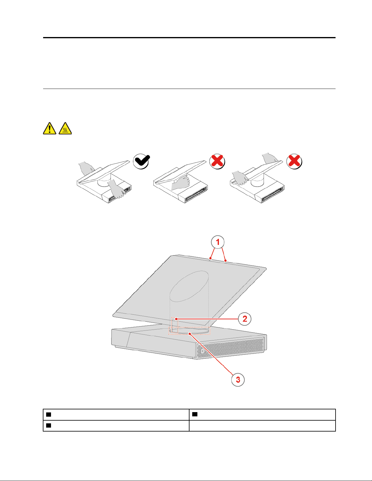
CAUTION:
Move the meeting console by holding the base instead of the hinge or the LCD panel.
Figure 1. Moving the meeting console
Figure 2. Front view
1 Internal microphones (2)
3 System-status indicator (LED ring)
© Copyright Lenovo 2018 1
2 Motion sensor

1 Internal microphone
Used to amplify your voice in a meeting without using an external microphone.
2 Motion sensor
When the meeting console is on, the motion sensor can detect whether you are in front of the screen. When
you exit a meeting and move away from the meeting console, the screen will dim after several minutes
(determined by your settings). When you move in front of the dimmed screen, it will brighten automatically.
Note: The screen will also brighten when you tap it.
3 System-status indicator
The LED ring at the bottom of the hinge shows the system status of the meeting console.
• Off: The meeting console is off.
• White light rotates and then is solid on: You enter Skype Room System, or log in to Skype Room
System successfully, or exit the meeting.
• Solid white: The meeting console is turned on or in the idle mode.
• Solid green: A meeting is in progress.
• Solid red: Your microphone is mute in a meeting.
Note: Only the basic behaviors of the LED ring are listed above.
2
Hub 500 User Guide and Hardware Maintenance Manual
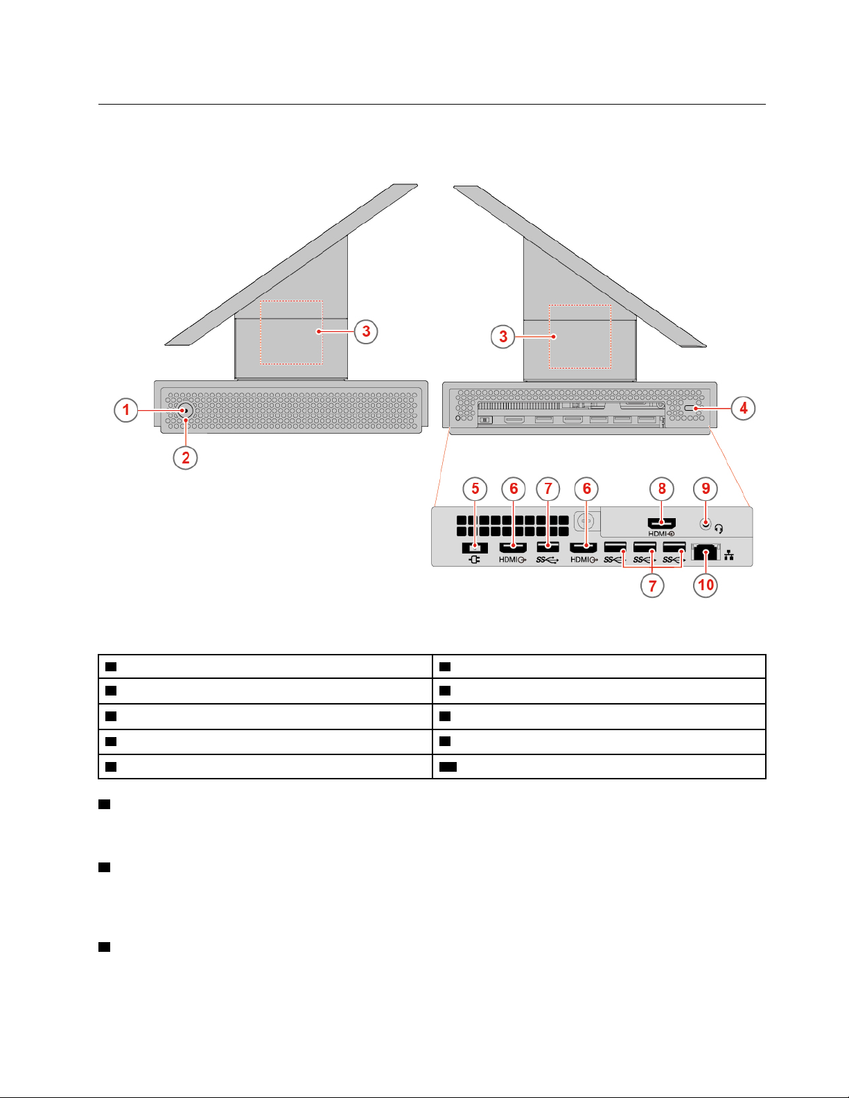
Right-side and left-side view
Note: Your meeting console model might look slightly different from the illustration.
Figure 3. Right-side and left-side view
1 Power indicator 2 Power button
3 Internal speakers (2) 4 Security-lock slot
5 Power adapter connector
7 USB 3.1 Gen 1 connectors (4)
9 Headset connector 10 Ethernet connector
1 Power indicator
6 HDMI
8 HDMI in connector
TM
out connectors (2)
This indicator is on when the meeting console is on.
2 Power button
Used to turn on your meeting console. When you cannot shut down the meeting console from the operating
system, press and hold the power button for four or more seconds to turn off the meeting console.
3 Internal speaker
Used to listen to the high-quality sounds from the meeting console without using a headset or headphones.
Chapter 1. Overview 3

4 Security-lock slot
Used to secure a Kensington-style cable lock.
5 Power adapter connector
Used to connect the power adapter to the meeting console for power supply.
6 HDMI out connector
Used to send audio and video signals from the meeting console to another audio or video device, such as a
high-performance monitor.
7 USB 3.1 Gen 1 connector
Used to connect a USB-compatible device. For optimal data transfer, connect a USB 3.1 Gen 1 device to a
USB 3.1 Gen 2 or USB 3.1 Gen 1 connector instead of a USB 2.0 connector.
8 HDMI in connector
Used to receive audio and video signals from an external computer with HDMI signals output.
9 Headset connector
Used to connect a headset to the meeting console.
To enable the headset function, do the following:
1. In the Skype mode, tap Settings ➙ Settings.
2. Enter the default administrator password “sfb” and tap Yes.
3. Tap Features, and then select Headset Microphone (Lenovo Hub500 Audio) in the Microphone for
Conferencing area.
4. Tap Save and Exit.
Note: The Bluetooth headset function can be enabled only in the administrator mode.
10 Ethernet connector
Used to connect an Ethernet cable for network access.
System board, Skype board, and video capture card
Note: See “Front view” on page 1 and “Right-side and left-side view” on page 3 for additional component
descriptions.
4
Hub 500 User Guide and Hardware Maintenance Manual
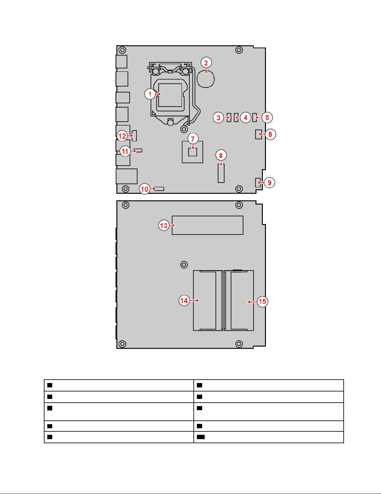
Figure 4. System board
1 Microprocessor socket
3 System fan connector 4 Skype board I
5 Skype board USB 2.0 connector (for the motion
2 Coin-cell battery
6 Skype board USB 2.0 connector (for audio signals)
sensor)
7 PCH
9 Power button board
8 M.2 Wi-Fi card slot
10 Skype board power connector
2
C connector
Chapter 1. Overview 5
11 Video capture module connector (connected to the
video capture card)
12 Skype board DisplayPort
®
connector
13 M.2 solid-state drive slot
15 Memory slot (DIMM2)
14 Memory slot (DIMM1)
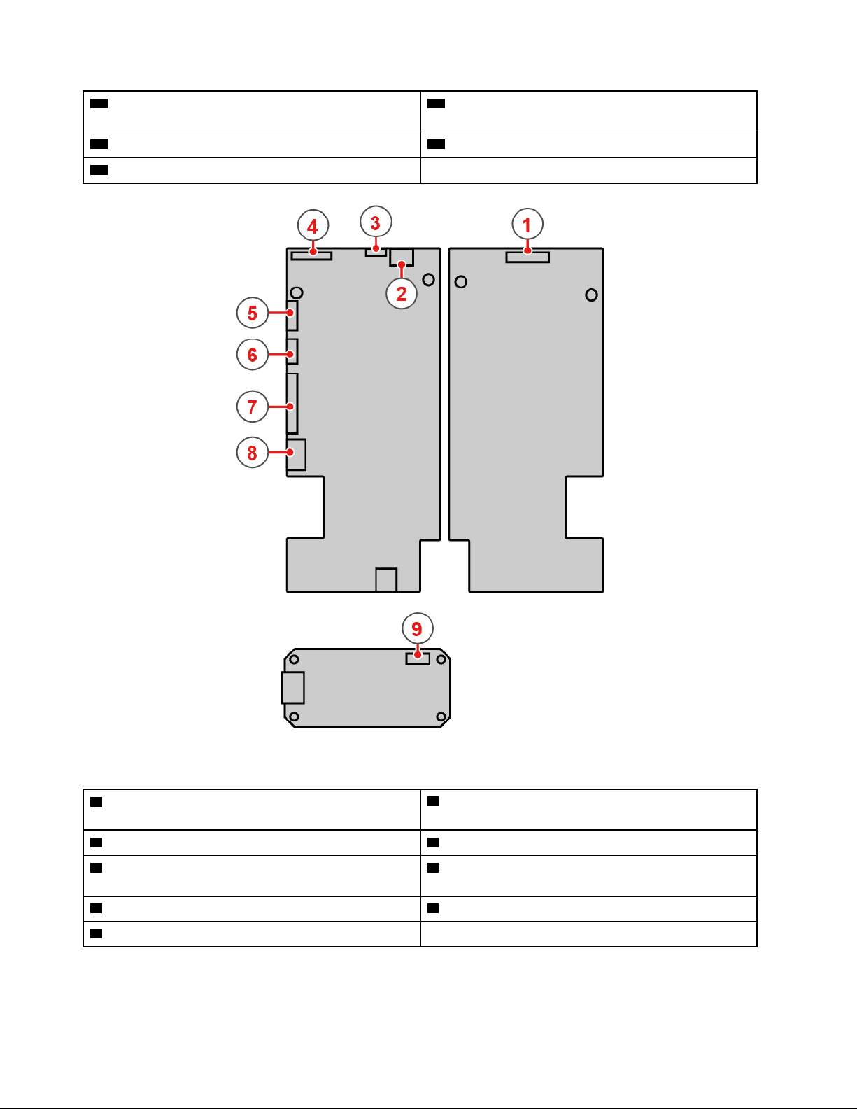
Figure 5. Skype board and video capture card
1 3-in-1 connector (connected to the integrated
2 Internal speaker connector
microphones, the LED board, and the motion sensor)
3 Touch connector 4 Embedded DisplayPort connector
5 USB 2.0 connector (for audio signals and the motion
2
6 I
C connector
sensor)
7 DisplayPort connector 8 Power connector
9 Video capture module connector
6 Hub 500 User Guide and Hardware Maintenance Manual

Machine type and model label
The machine type and model label identifies the meeting console. When you contact Lenovo for help, the
machine type and model information helps support technicians to identify the meeting console and provide
faster service. The machine type and model label is attached on the meeting console as shown.
Figure 6. Machine type and model label
Chapter 1. Overview 7

8 Hub 500 User Guide and Hardware Maintenance Manual

Chapter 2. Specifications
Power supply
• 90-watt automatic voltage-sensing power supply
Storage drives
• M.2 solid-state drive
Video features
• HDMI in connector
• HDMI out connector
Audio features
• Headset connector
• Internal microphones
• Internal speaker
Input/Output (I/O) features
• Audio connectors (headset)
• Display connectors (HDMI in and HDMI out)
• Ethernet connector
• USB 3.1 Gen 1 connector
Network features
• Ethernet LAN
• Wireless LAN
• Bluetooth
Physical dimensions
• Width: 280.0 mm (11.0 inches)
• Height: 180.0 mm (7.1 inches)
• Depth: 193 mm (7.6 inches)
Weight (without the package)
Maximum configuration as shipped: 2.5 kg (5.0 lb)
© Copyright Lenovo 2018 9

10 Hub 500 User Guide and Hardware Maintenance Manual
Chapter 3. Meeting console lock
This chapter provides instructions on how to lock your meeting console with the locking device to keep your
meeting console safe.
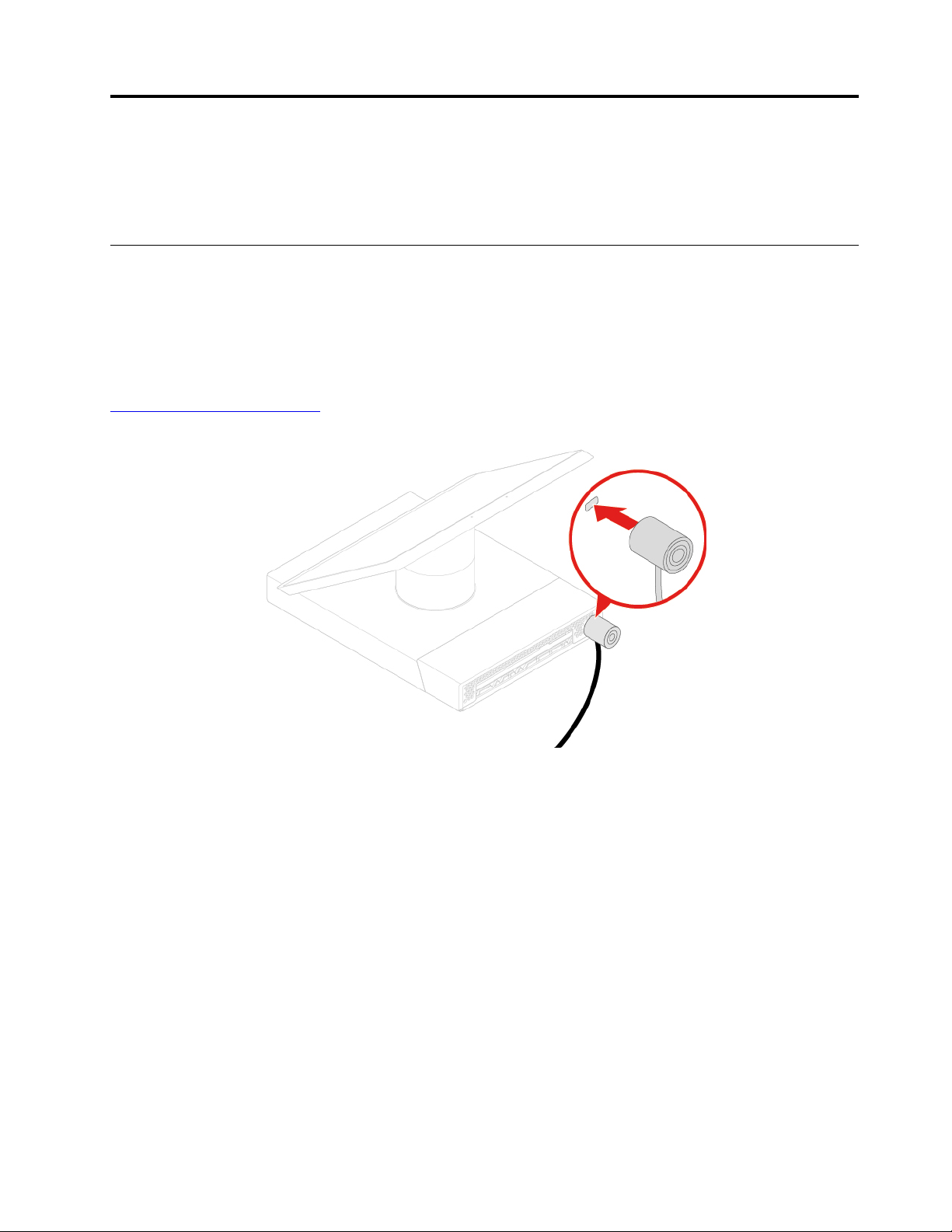
Attaching a Kensington-style cable lock
You can use a Kensington-style cable lock to secure your meeting console to a desk, table, or other
nonpermanent fixture. The cable lock connects to the security-lock slot at the rear of your meeting console.
Depending on the type selected, the cable lock can be operated with a key or combination. The cable lock
also locks the buttons used to open the system cover. This is the same type of lock used with many
notebook meeting consoles. You can order such a cable lock directly from Lenovo by searching for
Kensington at:
http://www.lenovo.com/support
Figure 7. Attaching a Kensington-style cable lock
© Copyright Lenovo 2018 11

12 Hub 500 User Guide and Hardware Maintenance Manual

Chapter 4. Replacing hardware
This chapter provides instructions on how to replace hardware for your meeting console.
Before replacing hardware
Attention: Do not open your meeting console or attempt any repairs before reading this section and the
Important Product Information Guide.
Notes before replacing hardware
• Use meeting console components provided only by Lenovo.
• When installing or replacing an option, use the appropriate instructions explained in this manual along with
the instructions that come with the option.
• In most areas of the world, Lenovo requires the return of defective CRUs. Information about this will come
with the CRU or will come a few days after the CRU arrives.
Handling static-sensitive devices
Do not open the static-protective package containing the new part until the defective part has been removed
and you are ready to install the new part. Static electricity, although harmless to you, can seriously damage
meeting console components and options.
When you handle options and other meeting console components, take these precautions to avoid staticelectricity damage:
• Limit your movement. Movement can cause static electricity to build up around you.
• Always handle options and other meeting console components carefully. Handle PCI/PCIe cards, memory
modules, system boards, and microprocessors by the edges. Never touch any exposed circuitry.
• Prevent others from touching the options and other meeting console components.
• Touch the static-protective package containing the part to a metal expansion-slot cover or other
unpainted metal surface on the meeting console for at least two seconds. This reduces static electricity
from the package and your body before you install or replace a new part.
• When possible, remove the new part from the static-protective package, and install it directly in the
meeting console without setting the part down. When this is not possible, place the static-protective
package on a smooth, level surface and place the part on the package.
• Do not place the part on the system cover or other metal surface.
Knowing FRUs (including CRUs)
• Field Replaceable Units (FRUs) are computer parts that a trained technician can upgrade or replace. FRUs
include all CRUs. For detailed FRU information, such as the FRU part numbers and supported meeting
console models, go to:
http://www.lenovo.com/serviceparts-lookup
• Customer Replaceable Units (CRUs) are computer parts that a user can upgrade or replace.
– Self-service CRUs: You can install self-service CRUs easily. These CRUs might be stand-alone,
latched, or secured by up to two screws. Examples of self-service CRUs include the keyboard, mouse,
any USB device. You are responsible for replacing all self-service CRUs.
– Optional-service CRUs: Handling optional-service CRUs requires some technical skills and simple tools
(such as a screwdriver). These CRUs are isolated parts within the computer. They are usually
© Copyright Lenovo 2018 13

concealed by an access panel that is secured by more than two screws. You must remove the screws
and panel to access the specific CRU. Optional-service CRUs can be removed and installed by users
or, during the warranty period, by a Lenovo service technician.
Before replacing FRUs
Before replacing any FRU, read the following:
• Only certified and trained personnel can service the meeting console.
• Before replacing an FRU, read the entire section about replacing the part.
• Be extremely careful during writing operations such as copying, saving, or formatting.
The sequence of the drives in the meeting console that you are servicing might have been altered. If you
select an incorrect drive, data or programs might be overwritten.
• Replace an FRU only with another FRU of the correct model.
When you replace an FRU, ensure that the model of the machine and the FRU part number are correct.
• An FRU should not be replaced because of a single, unreproducible failure.
Single failures can occur for a variety of reasons that have nothing to do with a hardware defect, such as
cosmic radiation, electrostatic discharge, or software errors. Consider replacing an FRU only when a
problem recurs. If you suspect that an FRU is defective, clear the error log and run the test again. If the
error does not recur, do not replace the FRU.
• Only replace a defective FRU.
Locating FRUs (including CRUs)
Notes:
• Self-service CRUs:
• Some of the following components are optional.
• To replace a component that is not in the list below, contact a Lenovo service technician. For a list of
Lenovo Support phone numbers, go to:
http://www.lenovo.com/support/phone
10 and 11
14 Hub 500 User Guide and Hardware Maintenance Manual
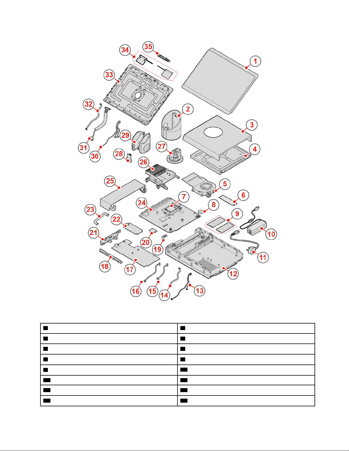
Figure 8. Locating FRUs (including CRUs)
1 Front panel 2 Hinge pipe
3 Upper cover 4 LED board
5 System fan
7 Microprocessor
9 Memory modules (2)
11 Power cord
13 Skype board audio cable 14 Skype board I
15 Skype board DisplayPort cable 16 Skype board power cable
6 M.2 solid-state drive
8 Coin-cell battery
10 Power adapter
12 Chassis
2
C cable
Chapter 4. Replacing hardware 15
17 Skype board 18 Skype board bracket
19 Wi-Fi card shield 20 Wi-Fi card
21 Skype board holder
23 Video capture module cable
25 Cable management door
27 Hinge assembly
29 Internal speakers (2) 30 3-in-1 cable (connected to the integrated
22 Video capture card
24 System board
26 Heat sink
28 Infrared board
microphones, the LED board, and the motion sensor)
31 Embedded DisplayPort cable 32 Touch cable
33 Back cover 34 Wi-Fi antennas
35 Internal microphones
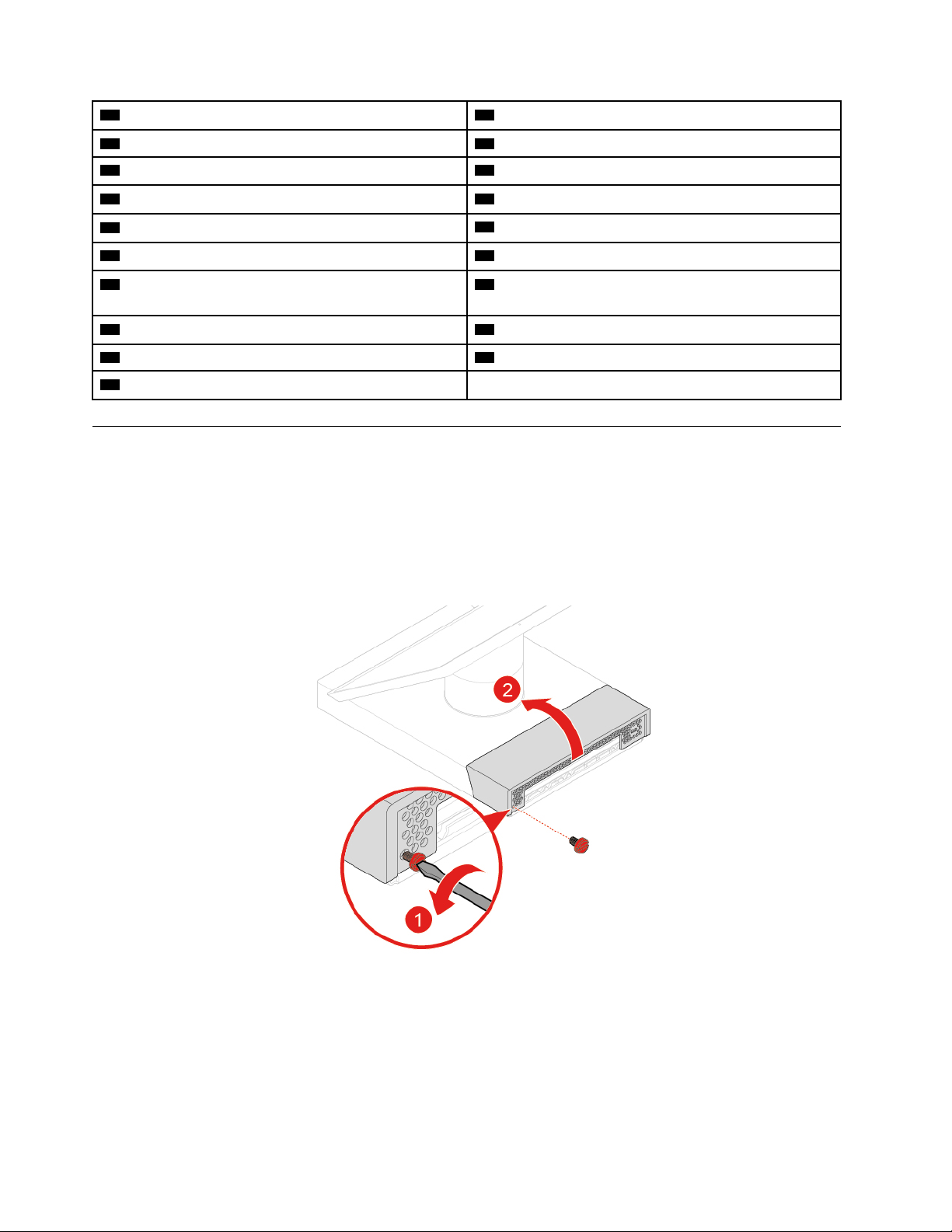
Replacing the cable management door
Attention: Do not open your meeting console or attempt any repairs before reading the Important Product
Information Guide.
1. Remove all connected devices, turn off the meeting console, and disconnect the power cord from the
electrical outlet.
2. Unlock the Kensington-style cable lock.
3. Replace the cable management door.
Figure 9. Opening the cable management door
16 Hub 500 User Guide and Hardware Maintenance Manual
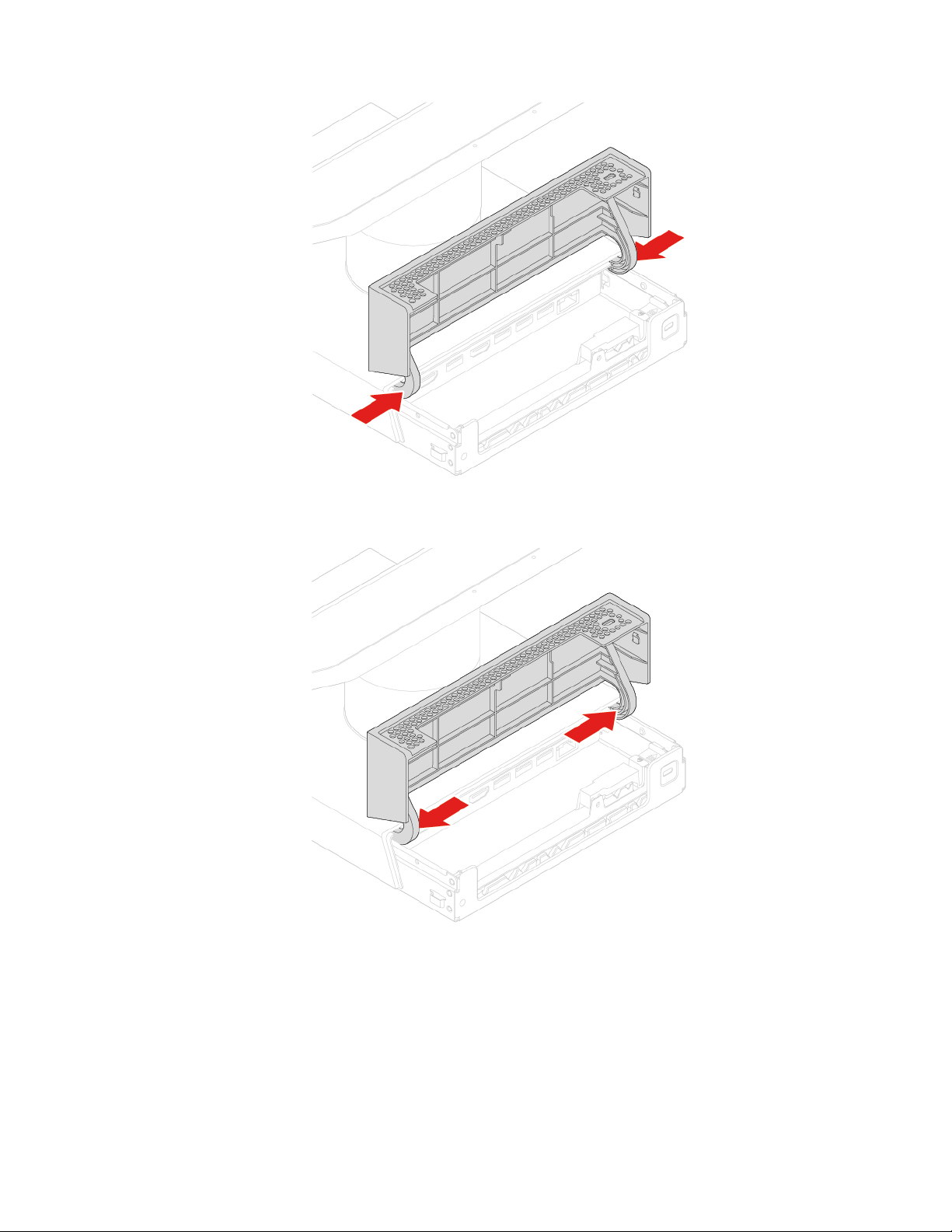
Figure 10. Removing the cable management door
Figure 11. Installing the cable management door
Chapter 4. Replacing hardware 17
 Loading...