

Page 1
PowerDRIVE-Positioning
GEL 6113
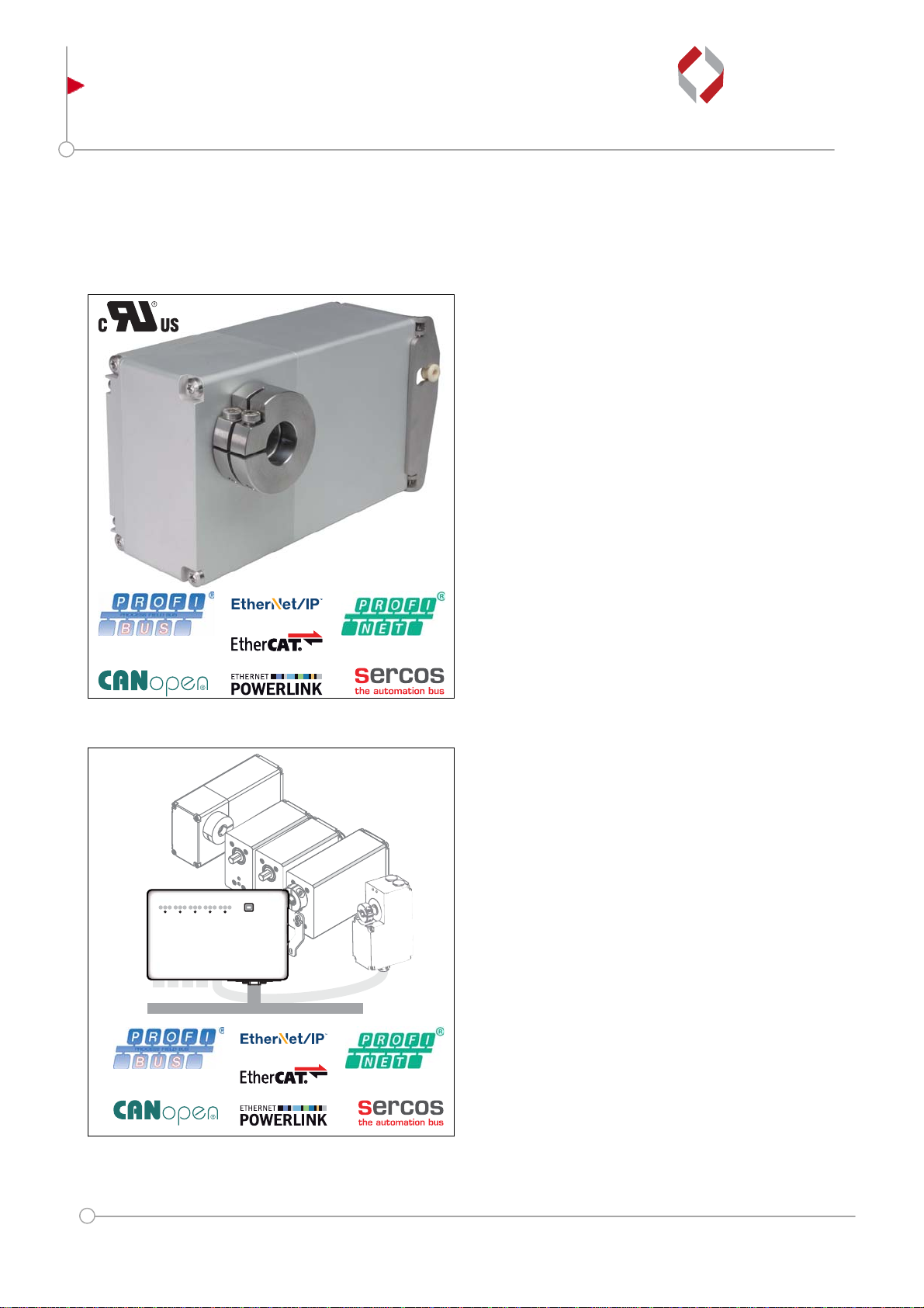
Positioning drive with through hollow shaft
LENORD
+
BAUER
... automates motion.
Technical information
Variable type of conn ecti on a nd int erfa c e
Issued 2017-08
General
The PowerDRIVE-Positioning GEL 6113 forms a compact
mechatronic unit comprising a brushless DCmotor, a 32-bit
microprocessor, a compact power amplifier and a powerful
gear, as well as a magnetic multiturn encoder.
Active system protection against thermal overload and
comprehensive system software allow load-dependent
duty cycles well above 25 %.
The rigid aluminium housing with its high degree of
protection (IP 67) is suitable for a wide range of
applications in various industrial areas.
Features
Nominal torques 5 Nm, 7 Nm, 10 Nm
Aluminium housing
Operating temperature -10 °C to +60 °C
BLDC motor
Magnetic-absolute multiturn encoder
- Accuracy: ±1.8° in the de-energised state
- Detection range: 114 turns, also in de-energised
state
Degree of protection IP67
Integrated communication interfaces
CANopen (CiA 402); PROFIBUS-DP (V0/V1);
Sercos III; POWERLINK; PROFINET IO / RT;
EtherCAT; EtherNet/IP
Optionally with cULus component recognition
PowerDRIVE-Box
On usage with the PowerDRIVE-Box all common
communication interfaces are available
Subject to technical modifications and typographical errors.
Internet: www.lenord.com
E-Mail: [email protected]
DS22-6113
Phone: +49 208 9963–0
Fax: +49 208 676292
Advantages
Either hybrid cable or plug outlet
Onboard joystick for straightforward commissioning
Monitoring of important system parameters ensures
reliable operation (overload protection)
Ready for use immediately after power on due to
absolute multiturn position detection
Maintenance-free due to sealed-for-life lubrication
Fields of application
Packaging machines
Food and bottling plants
Wood and plastic working machines
Printing presses and book binding machines
Extensive production plants
Lenord, Bauer & Co. GmbH
Dohlenstraße 32
46145 Oberhausen, Germany
Page 2

Description
System concept
The positioning drives belong to the product group
PowerDRIVE-Positioning and are a component of the
PowerDRIVE system.
Each positioning drive in the GEL 6113 series is an
intelligent adjustment unit for pushing onto the end of a
shaft or for attachment to a shaft or spindle.
The positioning drive can be integrated directly into a plant
control system via the communication interfaces
integrated.
PowerDRIVE-System
The PowerDRIVE-System is suitable for the efficient
integration of several positioning drives in a machine or
plant. The system consists of the following components:
PowerDRIVE-Positioning:
Positioning drive for fully automatic format adjustment
PowerDRIVE-Motion:
Positioning drive for cyclic operation
PowerDRIVE-Box:
Decentral control unit for up to 5 drives
PowerDRIVE-Connect:
Single cable concept (hybrid cable suitable for drag
chain)
PowerDRIVE-Lib:
Ready-made function blocks for integration in the
machine control system
PowerDRIVE-Support Tool:
Software for advanced commissioning and configuration
The usage of PowerDRIVE-Box and PowerDRIVEConnect significantly reduces the cabling effort for the
positioning drives. Instead of the usual two separate
cables for internal bus communication and a third cable to
supply power to the positioning drives, only ONE hybrid
cable suitable for use in drag chains is connected. In the
maximum configuration with 5 positioning drives
connected, the number of cables typically reduces from 15
to 5 due to PowerDRIVE-Connect. With the aid of the
PowerDRIVE-Box the overall system offers a high degree
of flexibility during integration, as it supports all common
communication interfaces.
Construction
The PowerDRIVE-Positioning GEL 6113 is operated with a
supply voltage of 24 V DC and supports fieldbus profiles
(CANopen (CiA 402); PROFIBUS-DP (V0/V1)) and
Industrial Ethernet protocols (Sercos III; POWERLINK;
PROFINET IO / RT; EtherCAT; EtherNet/IP
PowerDRIVE-Connect is available with either a plug
connection or hybrid cable.
The rigid housing made of anodised aluminium is
particularly robust and achieves the degree of protection
IP 67 due to the Viton shaft sealing ring.
The positioning drive is equipped with mechanical manual
adjustment so that the positioning drive can be actuated if
there is a fault, e.g. a power failure.
A USB service connector is accessible on the rear of the
device for service purposes.
The device variants with integrated fieldbus (CANopen
(CiA 402); PROFIBUS-DP (V0/V1)) have rotary selection
switches for setting the device ID and baud rate, as well as
an onboard joystick. The positioning drive can be operated
in the set-up mode using the joystick without prior PLC
programming. All elements are accessible on the rear of
the device.
).
Integrated absolute rotary encoder
A magnetic-absolute multiturn rotary encoder makes
reference search routines after a power failure or
emergency stop unnecessary. Due to the batteryless
encoder, the positioning drive detects its position after
power on and is immediately ready for use.
In the switched off state the drive shaft can be moved by
±57 turns without loss of the absolute position.
The absolute rotary encoder withstands high shock/
vibration loads.
2 DS22-6113 / (2017-08)
Page 3
Description
Mounting
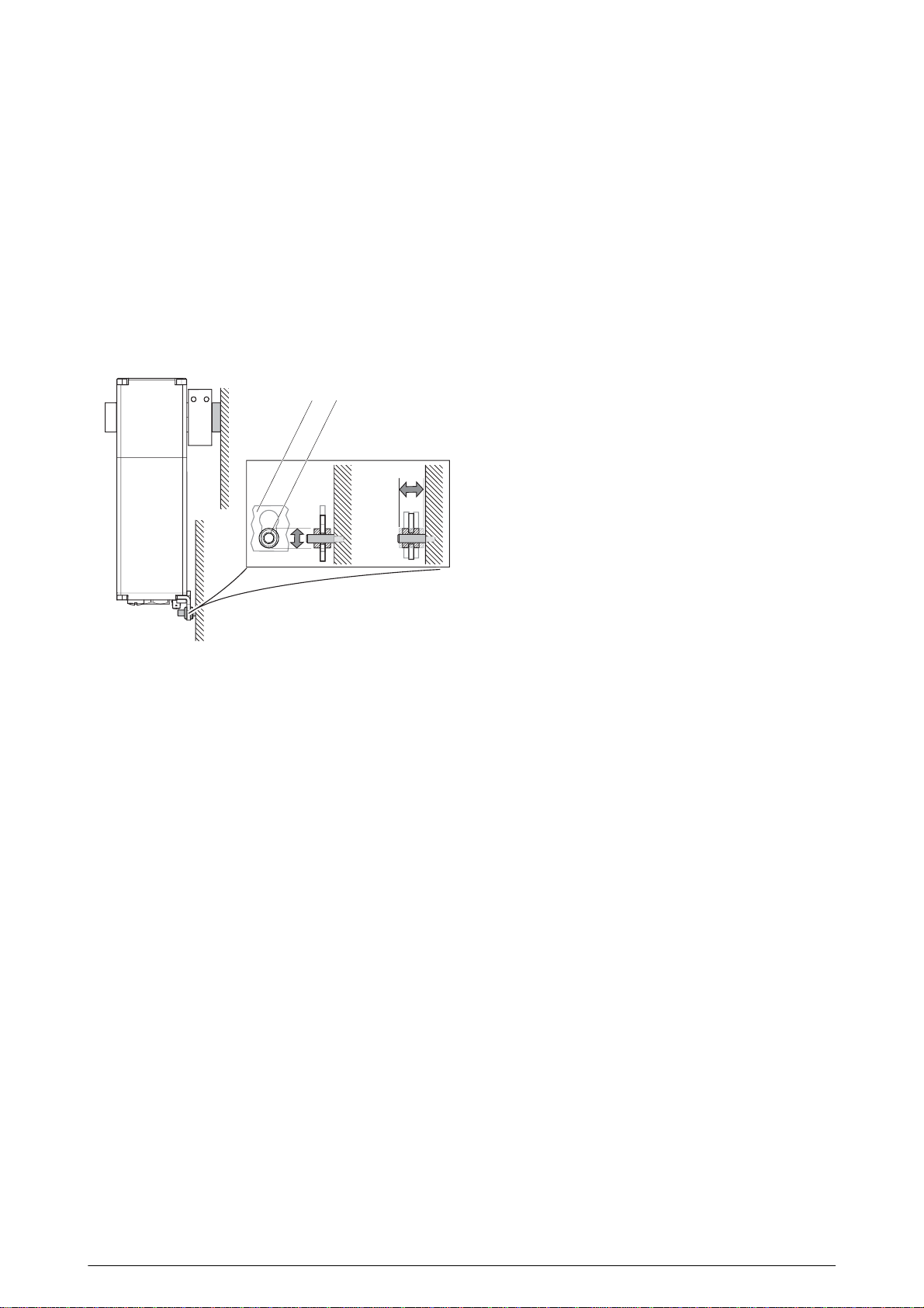
The mounting concept comprises a fixed-moving bearing.
The machine shaft supports the weight of the positioning
drive via the fixed bearing. For this purpose the positioning
drive is mounted directly and positively on the machine
shaft using a clamp coupling with a form-fit via the hollow
shaft. The torque support prevents the positioning drive
rotating and, as the moving bearing, compensates any
movements that occur on the drive shaft due to imbalance,
if necessary. The shape and design of the torque support
are order-specific. Various accessories are available for
mounting.
12
Recording imbalance movements at the moving bea rin g
(example with standard torque support from Lenord +
Bauer)
1 Torque support
2 Plain bearing
Modes of operation
The drive is designed for positioning at nominal torque.
The following intervals are valid for a duty cycle (ED) of
Duty cycle = 25 % at 100 % load torque, positioning
mode S2
(base time 4 minutes: ED = 1 minute, PD = 3 minutes)
Duty cycle ≤ 50 % with reduced load torque, dependent
on ambient parameters and application
Other methods of operation are protected by I
temperature monitoring as well as an adjustable current
limit. This protection permits a briefly increased breakaway
torque.
2
t and
Reliability
Important parameters such as motor power and device
temperature are monitored and in this way the positioning
drive actively protected against overload. The following
monitoring devices ensure trouble-free operation:
Soft start and shutdown via acceleration and
deceleration ramps
Over / undervoltage detection on the power circuit
supply and logic circuit supply
Lag error detection (drive shaft in relation to motor
shaft)
Temperature monitoring on the power amplifier and
inside the housing
Motor and power amplifier overload protection via I2t
monitoring and in combination with the PowerDRIVEBox by means of the maximum current.
General information on PowerDRIVEConnect
The hybrid cable PowerDRIVE-Connect is designed for
flexible application in drag chains. It is available in the
foodgrade, halogen-free and cULus recognised variants.
The hybrid cable is screened under the outer sheath. The
internal communication cores are fully insulated and
multiply screened.
All positioning drives are available with hybrid cable and
connectors and can be connected quickly and
straightforwardly to the PowerDRIVE-Box via the preassembled hybrid connecting cables that can be
configured as required.
Connectors with a quick-release coupling permit quick
connection and disconnection. The positioning drive is
therefore reliably and quickly disconnected from the power
supply for maintenance and service work in a matter of
seconds. Pre-assembled connection cables are available
for the connection, see "Technical information BZK".
DS22-6113 / (2017-08) 3
Page 4
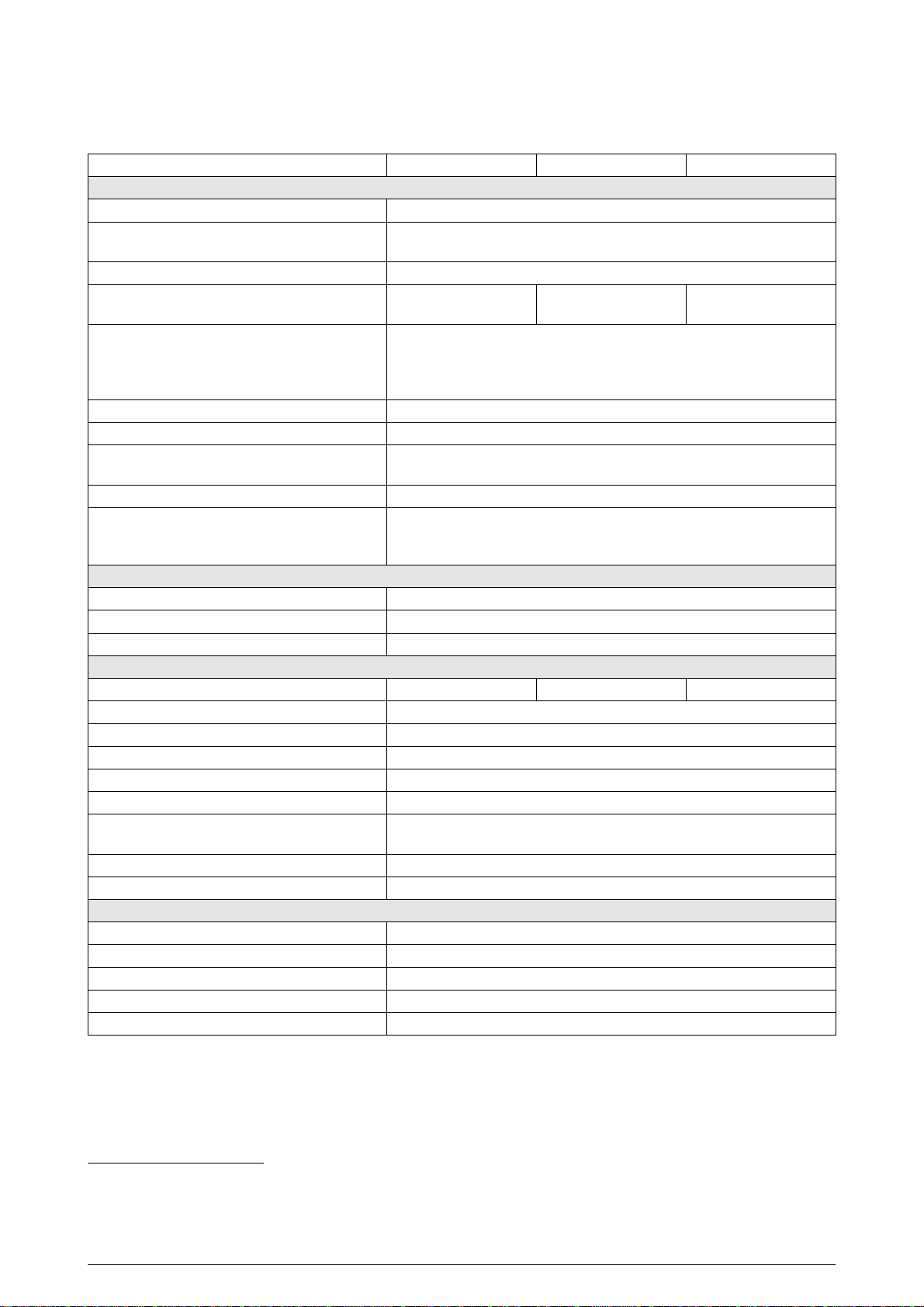
Technical data
Nominal torque (housing size) 05 (K) 07 (K) 10 (L)
Electrical data
Nominal voltage logic circuits 24 V DC -5% / +25%
Nominal voltage power circuits 24 V DC -5 % / +25%
(Attention: max. motor speed is voltage dependent!)
Nominal current logic circuits Max. 400 mA, external fuse required
Nominal current power circuits 2.0 A (max. 7.0 A),
external fuse required
Duty cycle in % (load-dependent ) Duty cycle = 25 % at 100 % load torque, positioning mode S2
(base time 4 minutes: ED = 1 minute, PD
Duty cycle ≤ 50 % with reduced load torque, dependent on ambient
parameters and application
Positioning range Unlimited
(2)
Fieldbus interfaces CANopen (CiA 402); PROFIBUS-DP (V0/V1)
Industrial Ethernet Sercos III; POWERLINK ; PROFINET IO / RT ; EtherCAT ;
EtherNet/IP
Dielectric strength √2 × 500 V DC; as per DIN EN 61439-1:2012-06
(3)
EMC
Electromagnetic immunity EN 61000-6-1:2007-10 /
EN 61000-6-2:2006-03
Electromagnetic emissions EN 61000-6-4:2011-09
Encoder data
Resolution 1000 increments per 360°
Accuracy ±1.8° in the de-energised state
Detection range 114 turns, also in de-energised state
Mechanical data
Nominal torque output shaft 5 Nm at 55 min
-1
Drive shaft Through hollow shaft Ø D = 20 mm
Shaft materials 1.4305
Housing material A: Aluminium AlMgSi
Weight Min. 2.33 kg
(4)
Degree of protection IP 67, EN 60529:2014-09, shaft sealing ring made of Viton
UL protection class
Type 1
(design C)
2
Shock resistance 150 m/s
Vibration resistance 50 m/s
(approx. 15 g); as per DIN EN 60068-2-27:2010-02
2
(approx. 5 g), 10 to 50 Hz; as per DIN EN 60068-2-6:2008-10
Ambient data
Assured operating temperature range 0 °C to +60 °C
Operating temperature range -10 °C to +60 °C
Storage temperature range -20 °C to +85 °C
Max. relative humidity of air 95%
Condensation Not permitted (condensation protection upon request)
2.8 A (max. 7.5 A),
external fuse required
(1)
= 3 minutes)
7 Nm at 55 min
-1
4.1 A (max. 10 A),
external fuse required
10 Nm at 55 min
-1
(1)
PD length of space
(2)
If the supply voltage is present, an electronic counter measures the positioning range over the detection range of the
measuring system.
(3)
Use only screened cables.
(4)
Depending on the type of connection and the housing size
4 DS22-6113 / (2017-08)
Page 5
Technical data
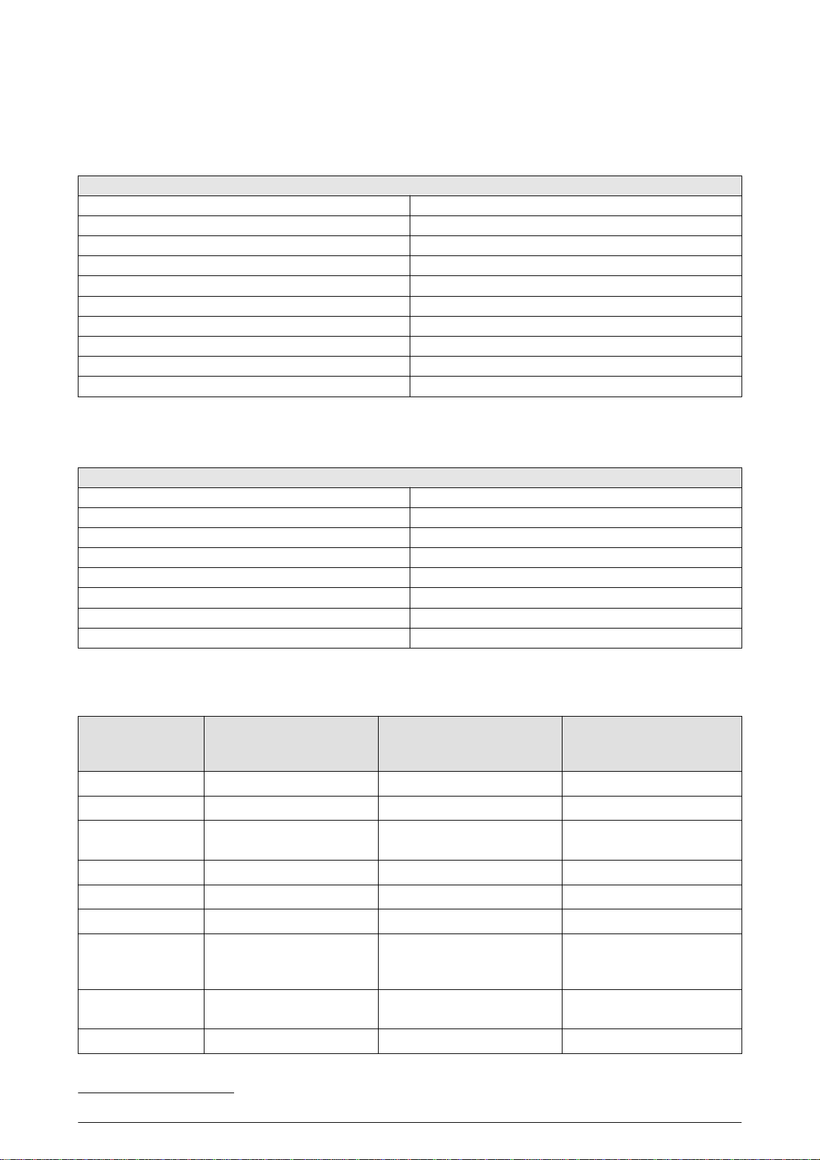
Connector M23
Type of connection H1 / H2 / H3
Technical data – coupling / connector (connector size M23)
Rated voltage Max. 30 V AC / DC
Current carrying capacity According to DIN EN 60512
Contact type (coupling / connector) Male / female
Housing material coupling / connector Nickel-plated brass (others upon request)
Union nut material Nickel-plated brass
Ambient temperature -20 °C to +130 °C
Degree of protection
Mating cycles > 500
Vibration resistance ≤ 200 m/s
Approval cULus recognised component (no. E247738)
Connector M17
Type of connection HS / S1 / S2 / S3
Technical data – coupling / connector (connector size M17)
Rated voltage Max. 30 V AC / DC
Current carrying capacity According to DIN EN 60512
Contact type (coupling / connector) Male / female
Housing material coupling / connector Brass, die-cast zinc and encapsulated in plastic
Ambient temperature -20 °C to +130 °C
Degree of protection
Mating cycles > 500
Approval cULus recognised component (no. E247738)
(1)
(1)
IP 66 / IP 67
2
IP 66 / IP 67
Technical data, cables
Hybrid cable Design 0
(standard)
Sheath material PUR, black, glossy PUR, black, matt PUR, black, matt
Cable properties Screened Screened Screened
Suitable for drag
chains
Food grade Yes No No
Halogen-free No Yes Yes
Cable diameter (d) 9.5 mm 9.5 mm 9.5 mm
Bending radius Permanently flexible: 10 × d
Peak operating
voltage
Temperature range -40 °C to +80 °C -40 °C to +80 °C -40 °C to +80 °C
Max. 350 V CAN bus
Max. 30 V DC (logic / power)
Yes Yes Yes
Fixed routing: 5 × d
(separate fuse protection)
Permanently flexible: 15 × d
Max. 30 V DC (logic / power)
Design 1
Freely moving: 10 × d
Fixed routing: 5 × d
Max. 300 V CAN bus
Design C
(cULus recognised
component)
Permanently flexible: 15 × d
Freely moving: 10 × d
Fixed routing: 5 × d
Max. 300 V CAN bus
Max. 30 V DC (logic / power)
(1)
In the screwed-in state, according to DIN EN 60529 / DIN 40050
DS22-6113 / (2017-08) 5
Page 6
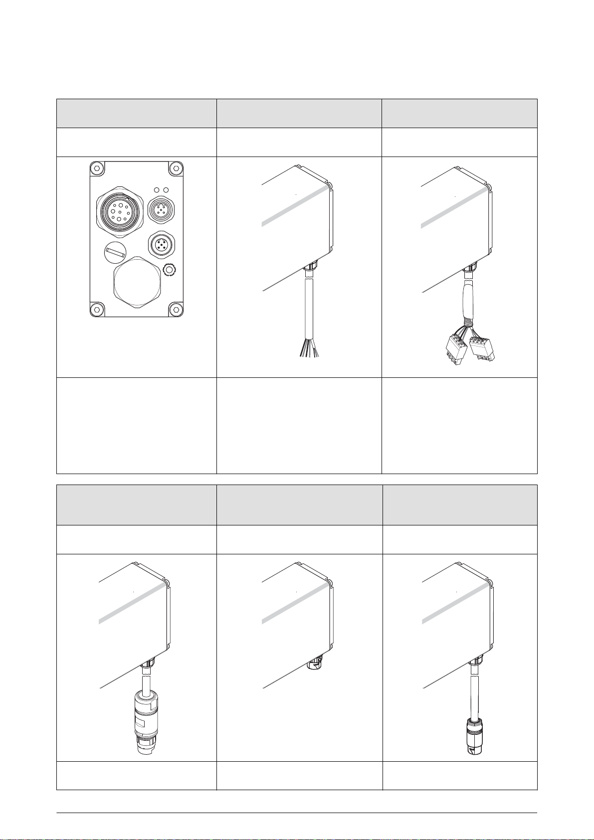
Device overview — types of connection
Plug outlet Flying lead Cable with spring-cage terminals for
Communication interfaces:
CO (CANopen)
DP (PROFIBUS-DP)
EC (EtherCAT)
IP (EtherNet/IP)
PL (POWERLINK)
RT (PROFINET IO / RT)
SC (SERCOS III)
H1: Cable length 30 cm
H2: Cable length 50 cm
H3: Cable length 100 cm
ST xx: Cable length can be selected
(1 m to 20 m)
Communication interface
CO (CANopen)
HS S1: Cable length 30 cm
Vx: Cable length can be selected
(1 m to 20 m)
the PowerDRIVE-Box connection
Communication interface
CO (CANopen)
S2: Cable length 50 cm
S3: Cable length 100 cm
Cable with M23 connector (coupling
with pin contacts)
Communication interface
CO (CANopen)
6 DS22-6113 / (2017-08)
M17 panel-mounting socket (pin
contacts)
Communication interface
CO (CANopen)
Cable with M17 connector (coupling
with pin contacts)
Communication interface
CO (CANopen)
Page 7
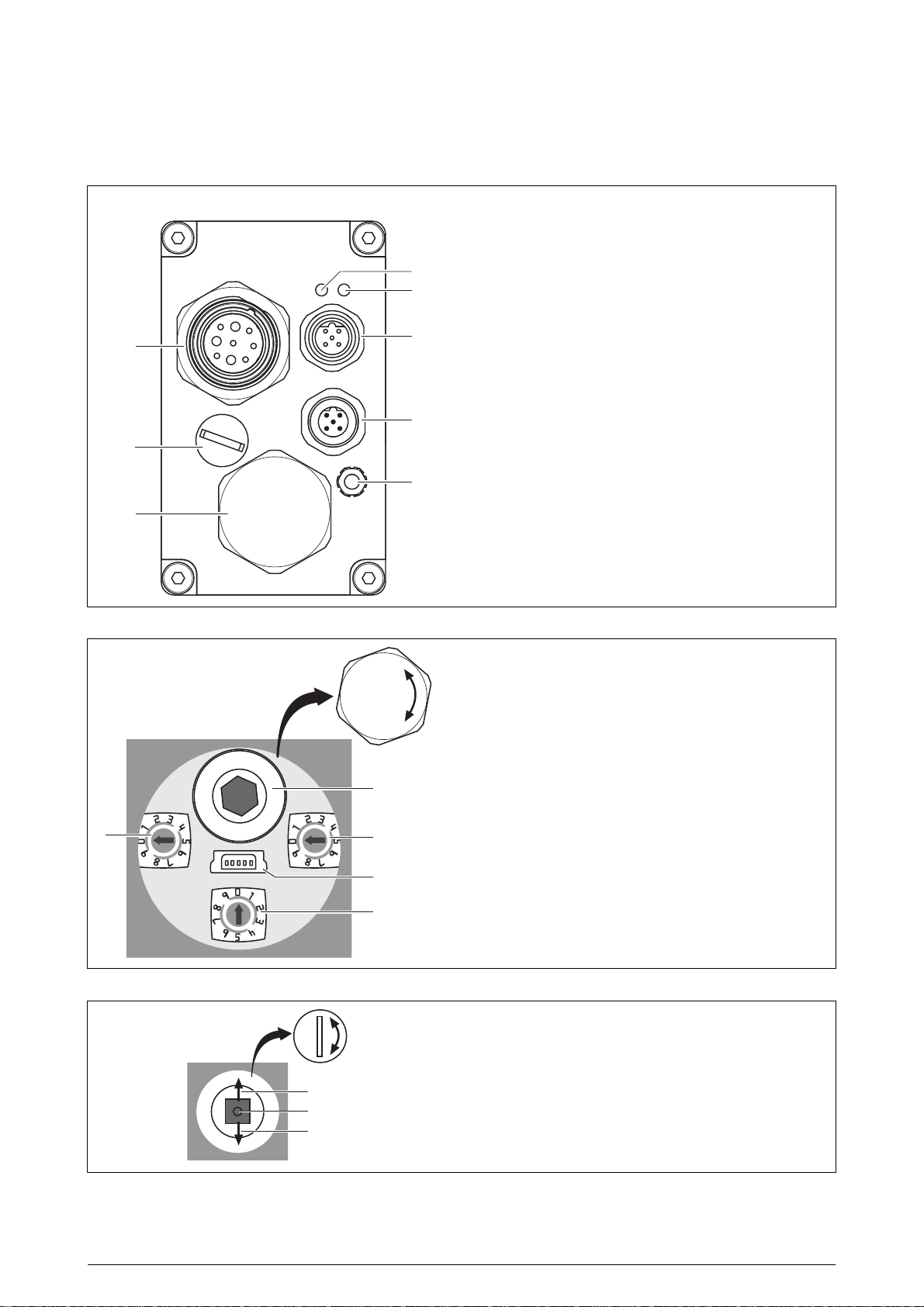
Rear side
Type of connection ST (here for PROFIBUS-DP)
Type of connection ST
Key
1 Status indication — device
2 Status indication — communication
3 Communication interface (IN)
4 Communication interface (OUT)
5 Function earth (stud M4)
6 Removable blanking plug for the setting elements
7 Removable blanking plug for manual adjustment
8 Supply connector
Setting elements, fieldbus variants (com m unication interface CO and DP)
6
a Manual emergency adjustment
b Rotary switch bus address units
c Service connector (mini USB)
a
e
b
c
d Rotary switch configuration
0 to 8 Baud rate
9 Service mode
e Rotary switch bus address decades
d
(no bus operation; jog mode via joystick
possible)
Manuelle Verstellung Feldbus-Varianten (Kommunikationsschnittstelle CO und DP)
7
Joystick
a Tippbetrieb Rechtslauf
a
b
b Fehlerquittierung (Druck)
c Tippbetrieb Linkslauf
c
DS22-6113 / (2017-08) 7
Page 8

Type of connection ST
Setting elements for Industrial Ethernet v ar ian ts (communication interfaces EC, SC, PL, RT and IP)
6
Pin layout – supply connector
Supply connector Pin identifier Signal identifier
M23
1
8
7
6
2
9
3
4
5
Pins
Pin layout – communication interfaces
CANopen PROFIBUS-DP Industrial Ethernet
a
a Manual emergency adjustment
b Service connector (mini USB)
c Push-button (for service purposes)
b
c
1 + 24 V DC logic circuits
2 GND logic circuits
6 + 24 V DC power circuits
8 GND power circuits
GND wires connected internally.
Sercos III; POWERLINK;
PROFINET IO / RT; EtherCAT
EtherNet/IP
;
M12 A-coded
1
4
2
5
23
3
5
14
IN OUT
Male Female
Pin IN / OUT
1 Cable screen
2n.c.
3CAN GND
4CAN high
5CAN low
M12 B-coded
1
4
5
23
5
124
3
IN OUT
Male Female
Pin IN OUT
1 n.c. 5 V bus voltage
2A-wire A-wire
3 n. c. GND Bus
4B-wire B-wire
5Cable screenCable screen
2 × M12 D-coded
3
124
Switch sockets
Pin IN / OUT
1 Transmission Data+
2Receive Data+
3 Transmission Data-
4 Receive Data-
8 DS22-6113 / (2017-08)
Page 9
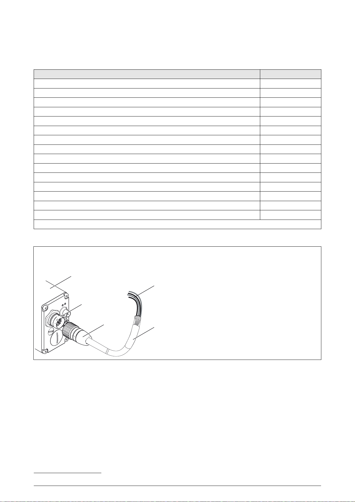
Type of connection ST
Connection accessories for type of connection ST
(1)
Description Item no.
Mating connector PROFIBUS-DP, M12, B-coded input (female) FS 3016
Mating connector PROFIBUS-DP, M12, B-coded output (male) FS 3017
Terminating resistor PROFIBUS-DP, M12, B-coded (male) FS 3041
Mating connector CANopen, M12, A-coded input (female) FS 3020
Mating connector CANopen, M12, A-coded output (male) FS 3021
Terminating resistor CANopen, M12, A-coded (male) FS 3040
Mating connector Industrial Ethernet input/output, M12, D-coded (male) FS 3039
PROFIBUS-DP, 1 connector, male, 10 m cable FS 3024
PROFIBUS-DP, 1 connector, female, 10 m cable FS 3025
PROFIBUS-DP, 1 connector, male, 2 m cable FS 3026
PROFIBUS-DP, 1 connector, female, 2 m cable FS 3027
PROFIBUS-DP, 2 connectors, female/male, 2 m cable FS 3028
Mating connector power supply M23 (female) FS 3038
Mating connector power supply M23 (female, angled) FS 3067
Connection cable power supply M23 (female) and flying lead BZK23S1N_ _ L
(a)
for _ _ cable length, state in m (min. 3 m / max. 20 m)
(a)
Power supply cable connection accessories (see Technical information BZK)
Connection cable BZK23S1NxxL / BZK23S1UxxL /
BZK23S1CxxL
(xx = length in m)
ST
4
1
2
3
Power supply cable for the
positioning drive with type of connection ST
ST Positioning drive with type of connection ST
1 Supply connector on the positioning drive
2 Connector 1/connector design S1
3Design
N 16 AWG food grade
U 16 AWG halogen-free or
C 14 AWG cULus recognised
4 Connector 2: L
(flying lead)
(1)
Other accessories: fieldbus cable, couplings etc. upon request
DS22-6113 / (2017-08) 9
Page 10
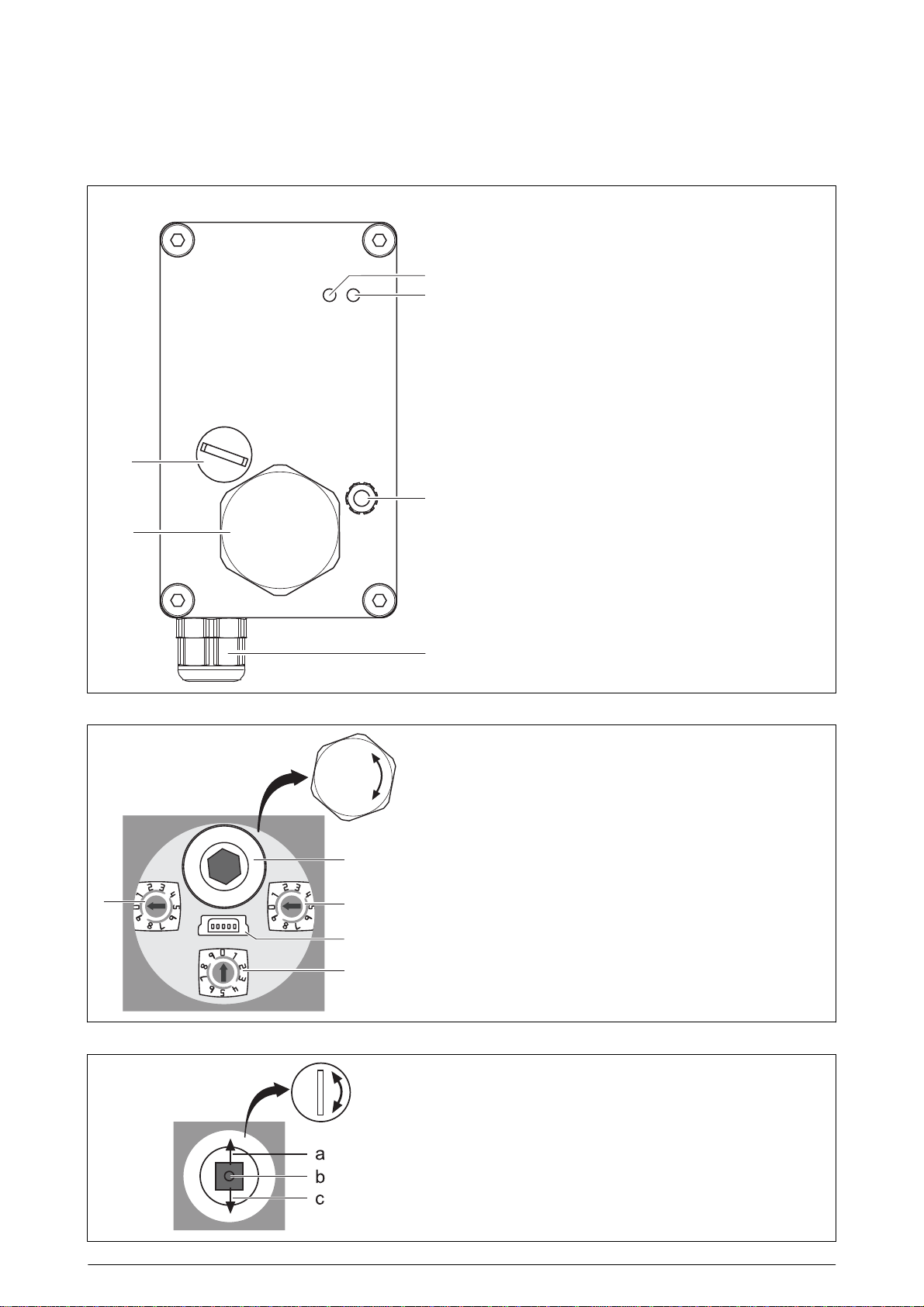
Type of connection H1 / H2 / H3 / S1 / S2 / S3 / xx / Vx
Rear side
Type of connection H1 / H2 / H3 / S1 / S2 / S3 / xx / Vx
Key
1 Status indication — device
2 Status indication — communication
3 Function earth (stud M4)
4 M16 cable gland
5 Removable blanking plug for the setting elements
6 Removable blanking plug for manual adjustment
Setting elements CANopen (communication interface CO)
5
a Manual emergency adjustment
b Rotary switch bus address units
c Service connector (mini USB)
a
e
Manual adjustment CANopen (communica tion interface CO)
b
c
d
d Rotary switch configuration
e Rotary switch bus address decades
6
Joystick
a Jog mode clockwise rotation
b Acknowledge error (pressure)
c Jog mode counter-clockwise
0 to 8 Baud rate
9 Service mode
(no bus operation; jog mode via joystick possible)
10 DS22-6113 / (2017-08)
Page 11
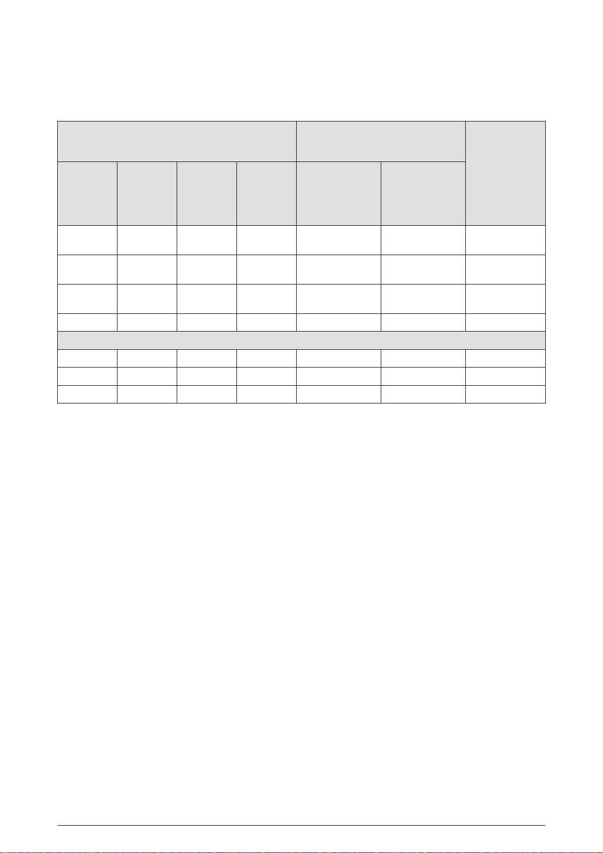
Type of connection H1 / H2 / H3 / S1 / S2 / S3 / xx / Vx
Terminal assignment xx / Vx
Type of connection xx:
Core colour/
core no.
Design 0
red/1 0.5 mm
red/2 1.5 mm
black/2 1.5 mm
black/1 0.5 mm
black 0.14 mm
green 0.25 mm
yellow 0.25 mm
cross-
section
flying lead
Design 1
2
2
2
2
2
0.14 mm
2
0.25 mm
2
0.25 mm
cross-
section
0.5 mm
1.5 mm
1.5 mm
0.5 mm
2
2
2
2
2
2
2
cross-
section
Design C
0.5 mm
2.5 mm
2.5 mm
0.5 mm
0.14 mm
0.25 mm
0.25 mm
Type of connection Vx:
pre-assembled for the
PowerDRIVE-Box connection
4-pole spring-cage
terminal (internal
positioning drive
communication)
pin identifier
2
2
2
2
–3+24 V logic
–1+24 V power
– 2 GND power
–4GND logic circuits
2
2
2
1 – CAN GND
3 – CAN low
2 – CAN high
Signal
identifier
4-pole spring-cage
terminal
(positioning drive
power supply)
pin identifier
circuits
circuits
circuits
DS22-6113 / (2017-08) 11
Page 12
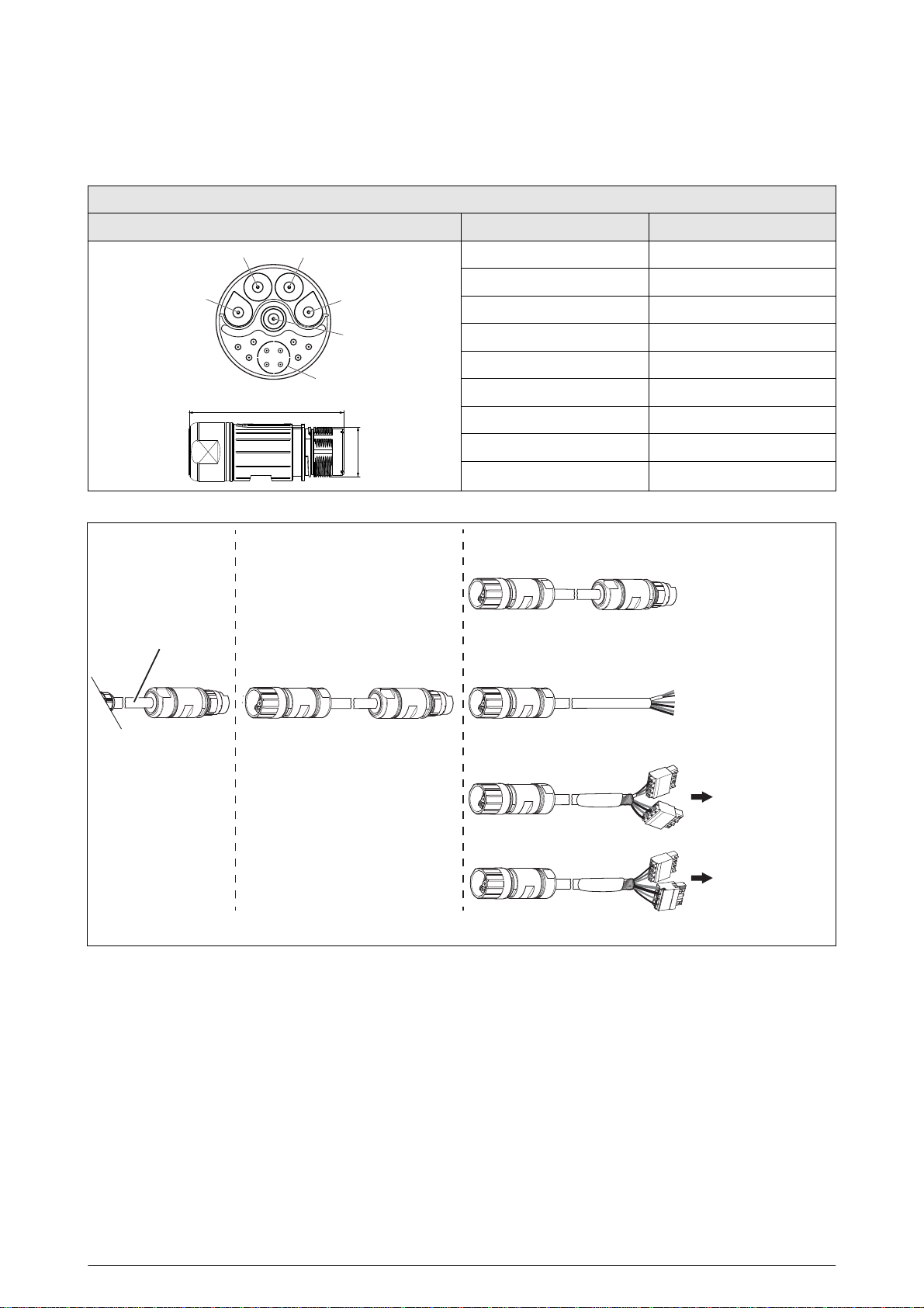
Type of connection H1 / H2 / H3 / S1 / S2 / S3 / xx / Vx
A
E
Pin layout H1 / H2 / H3
M23 connector
Coupling with pin contacts Pin identifier Signal identifier
BC
63
5
9
42
72
1
10
7
8
S
D
M23 x 1
A +24 V logic circuits
B GND logic circuits
C GND power circuits
D +24 V power circuits
E Cable screen
7 CAN high
8CAN GND
9CAN low
S CAN screen
Connection accessories H1 / H2 / H3 (see Technical information BZK)
BZK23S0NxxK
BZK23S0UxxK
BZK23S0CxxK
H1: 30 cm
H2: 50 cm
H3: 100 cm
M23
optional
BZK23S0NxxK
BZK23S0UxxK
BZK23S0CxxK
BZK23S0NxxL
BZK23S0UxxL
BZK23S0CxxL
BZK23S0NxxV
BZK23S0UxxV
BZK23S0CxxV
xx = length in m
PowerDRIVEBox
PowerDRIVEBox
12 DS22-6113 / (2017-08)
Page 13
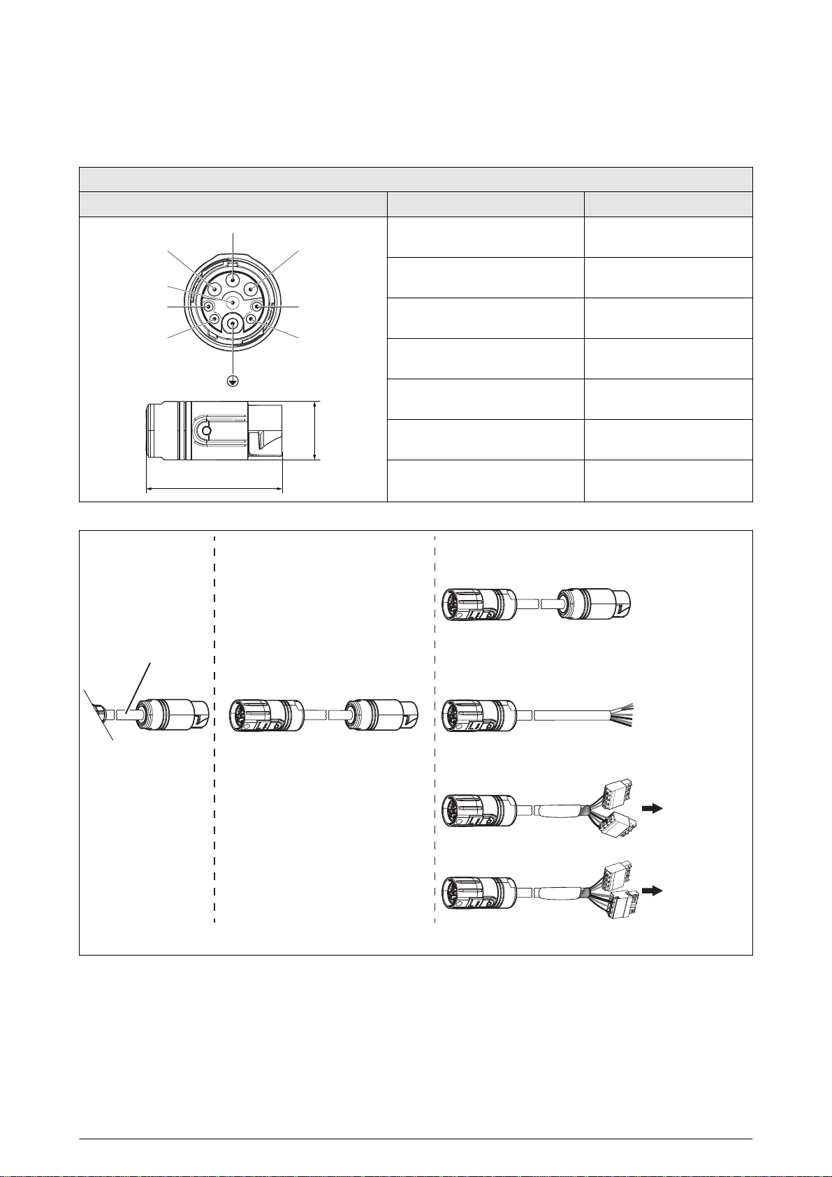
Type of connection H1 / H2 / H3 / S1 / S2 / S3 / xx / Vx
A
Pin layout S1 / S2 / S3
Coupling with pin contacts Pin identifier Signal identifier
M17 connector
B
C
5
4
3
41.4
Connection accessories S1 / S2 / S3 (see Technical information BZK)
1
2
ø18.7
BZK17S0NxxK
BZK17S0UxxK
BZK17S0CxxK
S1: 30 cm
S2: 50 cm
S3: 100 cm
M17
optional
BZK17S0NxxK
BZK17S0UxxK
BZK17S0CxxK
BZK17S0NxxL
BZK17S0UxxL
BZK17S0CxxL
A +24 V logic circuits
B +24 V power circuits
C GND power circuits
1 GND logic circuits
2CAN GND
3CAN low
4 CAN high
BZK17S0NxxV
BZK17S0UxxV
PowerDRIVEBox
BZK17S0CxxV
PowerDRIVEBox
xx = length in m
DS22-6113 / (2017-08) 13
Page 14

Type of connection HS
Rear side
Type of connection HS
Key
1 Status indication — device
2 Status indication — communication
3 Function earth (stud M4)
4 M17 panel-mounting socket with pin contacts
5 Removable blanking plug for the setting elements
6 Removable blanking plug for manual adjustment
Setting elements CANopen (communication interface CO)
5
a Manual emergency adjustment
b Rotary switch bus address units
c Service connector (mini USB)
a
e
b
c
d Rotary switch configuration
e Rotary switch bus address decades
d
Manual adjustment CANopen (communica tion interface CO)
0 to 8 Baud rate
9 Service mode
(no bus operation; jog mode via joystick possible)
6
Joystick
a Jog mode clockwise rotation
b Acknowledge error (pressure)
c Jog mode counter-clockwise
14 DS22-6113 / (2017-08)
Page 15
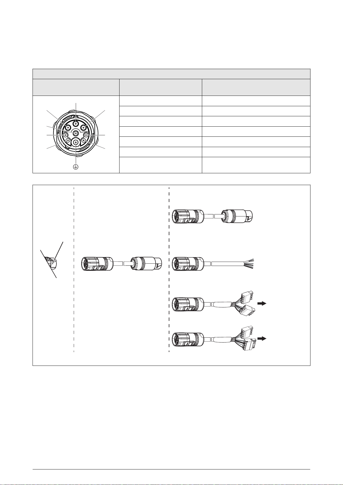
Pin layout HS
A
Type of connection HS
M17 connector
Panel-mounting socket with pin
contacts
B
C
5
4
3
Connection accessories HS (see Technical information BZK)
1
2
Pin identifier Signal identifier
A +24 V logic circuits
B +24 V power circuits
C GND power circuits
1 GND logic circuits
2CAN GND
3CAN low
4CAN high
BZK17S0NxxK
BZK17S0UxxK
BZK17S0CxxK
optional
HS
BZK17S0NxxK
BZK17S0UxxK
BZK17S0CxxK
BZK17S0NxxL
BZK17S0UxxL
BZK17S0CxxL
M17
BZK17S0NxxV
BZK17S0UxxV
PowerDRIVEBox
BZK17S0CxxV
PowerDRIVEBox
xx = length in m
DS22-6113 / (2017-08) 15
Page 16
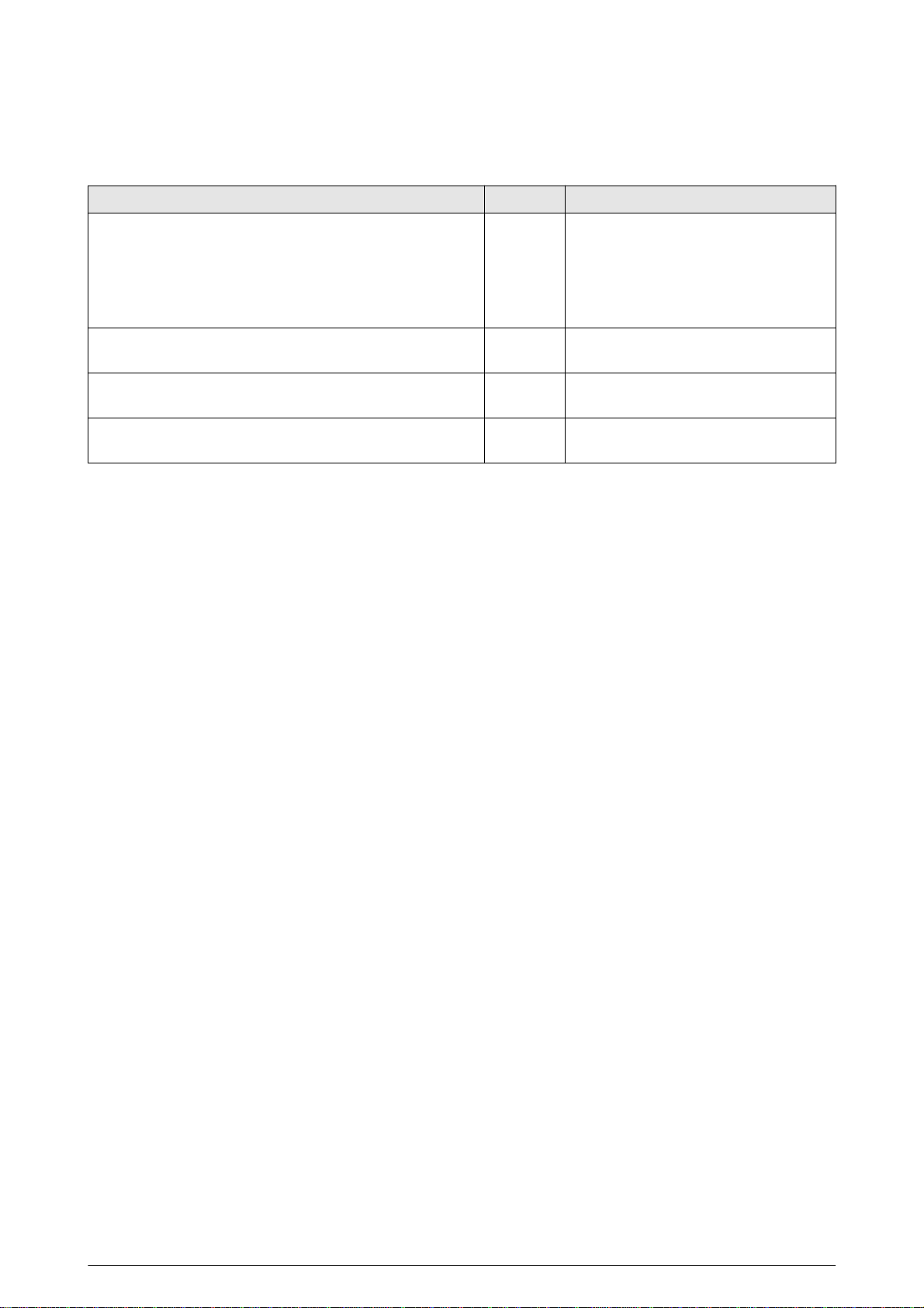
Accessories
Mechanical accessories (not includ ed in the scope of supp ly )
Identifier: Item no. Comment:
Clamp coupling for shaft diameter:
— 16 mm
— 17 mm
— 18 mm
— 19 mm
— 20 mm
Plain bearing accessories package
(Contents: 5 pcs. plain bearing, item no. OG 0001)
Headless screws accessories package
(Contents: 5 pcs. headless screw M5 × 20, item no. VS 3412)
Torque support screws accessories package
(Contents: 10 pcs. screw M5 × 8, item no. VS 2107)
MZ 1335
MZ 1354
MZ 1356
MZ 1355
MZ 1339
ZB61X01
ZB61X02
ZB61X03 Available for positioning drives with
option 0
16 DS22-6113 / (2017-08)
Page 17
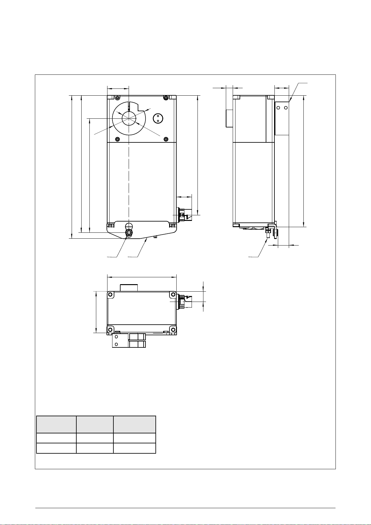
PowerDRIVE-Positioning GEL 6113, housing size L, option R
Dimensional drawings
207
198.5
165
Ø 48
31.5
Ø <20
22.3
173
10
21
A
L
16
BCD
100
15
60
A Clamp coupling can be fitted on both sides
B Function earth (stud M4)
C Torque support right, GZ 1167
D Plain bearing OG 0001
Note: Application point for the torque support always on the side of the clamp coupling.
Dimension “L” depending on the housing size
Nominal
torque
05, 07 K 170
10 L 190
All dimensions stated in mm (≈ approximate dimension)
General tolerance DIN ISO 2768 medium
Housing
size
Dimension “L”
DS22-6113 / (2017-08) 17
Page 18
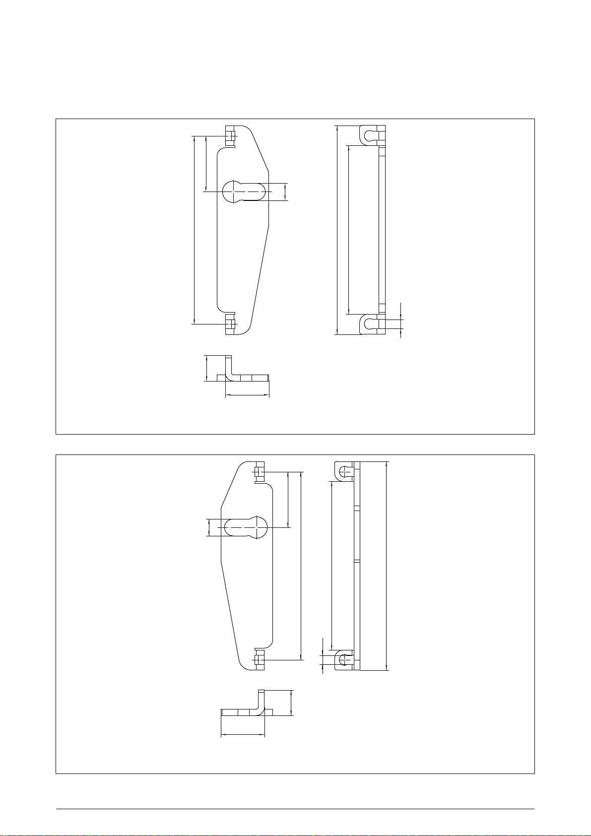
Dimensional drawings
Torque support left, GZ 1168 (part of option L)
27
8.1
91
t = 3
12.3
21
All dimensions stated in mm (≈ approximate dimension)
General tolerance DIN ISO 2768 medium
Torque support right, GZ 1167 (part of option R)
101
81.6
4.4
27
8.1
21
t = 3
12.3
91
81.6
4.4
101
All dimensions stated in mm (≈ approximate dimension)
General tolerance DIN ISO 2768 medium
18 DS22-6113 / (2017-08)
Page 19
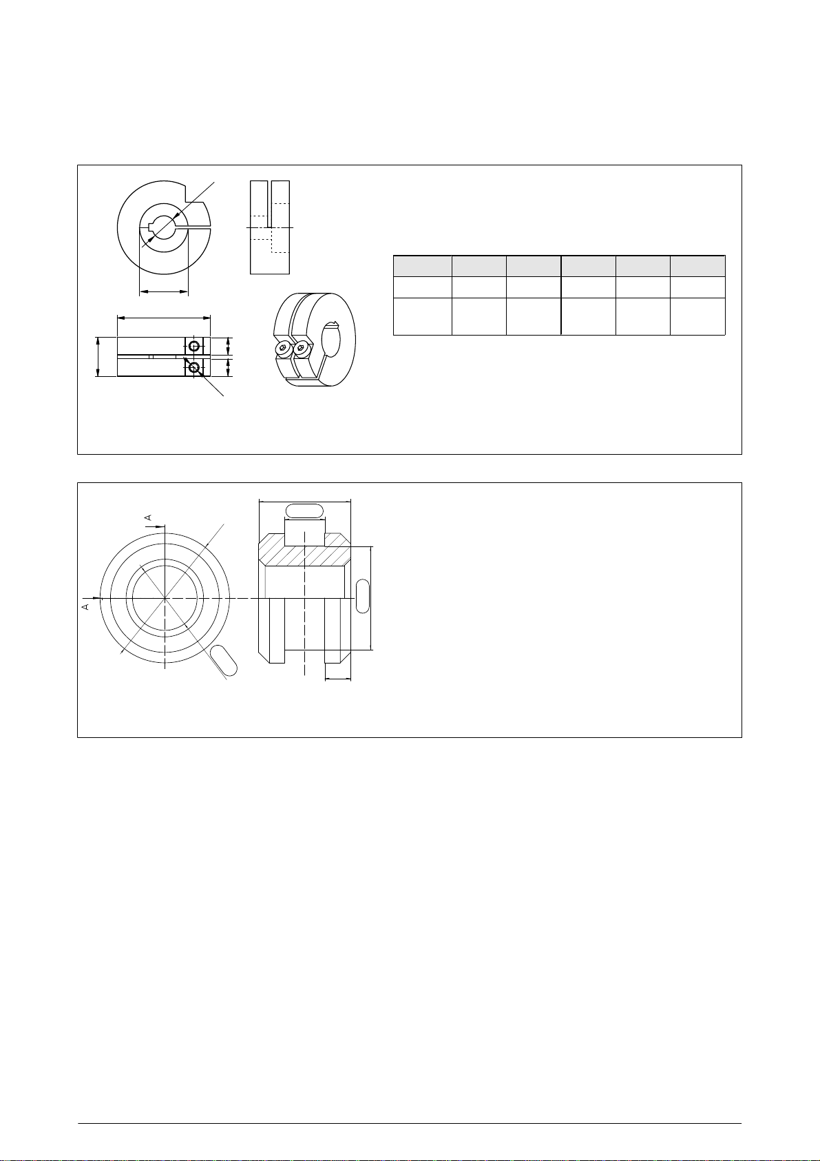
Clamp coupling (mechanical accessories)
d
25
48
99
20
M5
All dimensions stated in mm (≈ approximate dimension)
General tolerance DIN ISO 2768 medium
Dimensional drawings
For shaft diameter d from 16 mm to 20 mm
MZ 1335 MZ 1354 MZ 1356 MZ 1355 MZ 1339
d [mm] 16
Screws
DIN 6912
H7
M5 M5 M5 M5 M5
17
H7
18
H7
19
H7
20
H7
Plain bearing OG 0001 (part of option L and R)
7.1
±0.05
3.1
ø 10
0
ø 5
C11
2
All dimensions stated in mm (≈ approximate dimension)
General tolerance DIN ISO 2768 medium
Section A-A
-0.05
ø 8
DS22-6113 / (2017-08) 19
Page 20
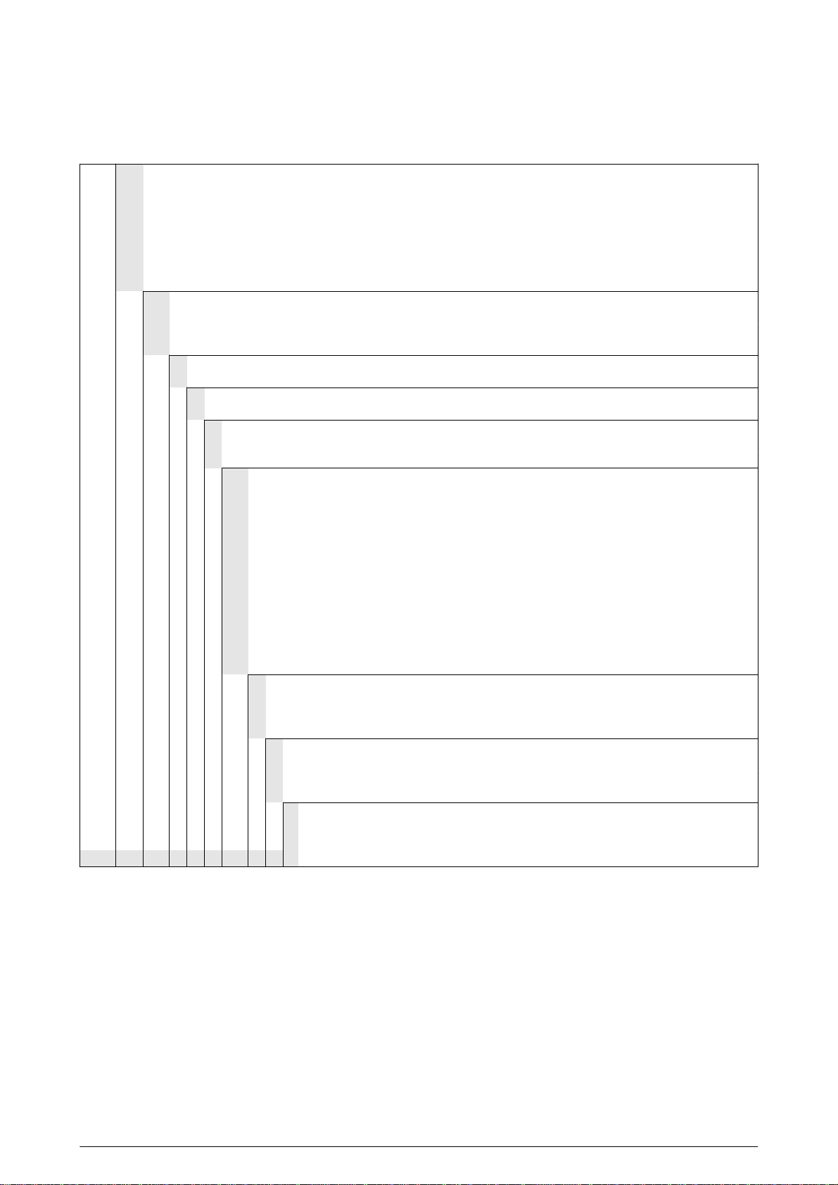
Type code
Type code GEL 6113
Communication interface
CO CANopen CiA 402
DP PROFIBUS-DP V0/V1
EC EtherCAT
IP EtherNet/IP
PL POWERLINK
RT PROFINET IO / RT
SC Sercos III
Nominal torque
05 5 Nm
07 7 Nm
10 10 Nm
Shaft in mm
U 20 mm through hollow shaft
Housing material
A Aluminium AlMgSi
Housing size
K Short (housing length L = 170 mm)
L Long (housing length L = 190 mm)
Type of connection
ST Connector (standard: M12 fieldbus, M23 supply)
HS M17 panel-mounting socket with pin contacts
S1 30 cm hybrid cable and M17 coupling with pin contacts
S2 50 cm hybrid cable and M17 coupling with pin contacts
S3 100 cm hybrid cable and M17 coupling with pin contacts
H1 30 cm hybrid cable and M23 coupling with pin contacts
H2 50 cm hybrid cable and M23 coupling with pin contacts
H3 100 cm hybrid cable and M23 coupling with pin contacts
Vx Hybrid cable pre-assembled with connection terminals for PowerDRIVE-BOX,
Cable length V1 = 1 m; V2 = 3 m; V3 = 5 m; V4 = 8 m; V5 = 10 m; V6 = 13 m; V7 = 15 m;
V8 = 18 m; V9 = 20 m
xx xx m hybrid cable with flying lead, length in m (xx = 01…20; standard: 3 m)
Design
0 Standard
1 Separate fuse protection
C cULus recognised component
Option
0 Without torque support, with spacing bolt
L Torque support standard left (GZ 1168 and plain bearing OG 0001)
R Torque support standard right (GZ 1167 and plain bearing OG 0001)
Degree of protection
3 IP 67 (with shaft sealing ring and protection against humidity), design C:
6113 _ _ _ _ _ _ _ _ _ _ _ _
additionally UL protection class type 1
20 DS22-6113 / (2017-08)
Page 21
Type code
Instructions for the type of connection
Type of connection ST
The positioning drive can be connected directly to a plant control system.
Type of connection HS / H1 / H2 / H3 / S1 / S2 / S3 / xx / Vx
The positioning drive is supplied with PowerDRIVE-Connect (hybrid cable) and connected via the PowerDRIVE-Box with
the plant control system.
Restrictions
Type of connection
The types of connection HS / H1 / H2 / H3 / S1 / S2 / S3 / xx / Vx are only available with communication interface CO
(CANopen).
Type of connection ST:
Communication interfaces CO, DP: only available with design 0
Communication interfaces EC, IP, PL, RT, SC: only available with design 0 or 1
Housing size/nominal torques
Brushless DC motors in housing size K or L are available. As a result there are different drive torques and housing
lengths.
Nominal torque Housing size (length of housing)
05 5 Nm at 55 min
07 7 Nm at 55 min
10 10 Nm at 55 min
Design
The cULus component recognition (E196161) requires for the usage of the positioning drives in design C the usage of
the PowerDRIVE-Box (E483619) GEL6505A␣␣␣␣␣␣C or GEL6505B␣␣␣␣␣␣C in combination with PowerDRIVEConnect BZK␣␣␣␣␣␣␣␣. Usage is also limited to the application area in "NFPA 79 - Electrical Standard for Industrial
Machinery".
-1
K (170 mm)
-1
K (170 mm)
-1
L (190 mm)
DS22-6113 / (2017-08) 21
Page 22

Your notes:
22 DS22-6113 / (2017-08)
Page 23

Your notes:
DS22-6113 / (2017-08) 23
Page 24

Lenord, Bauer & Co. GmbH
Dohlenstraße 32
46145 Oberhausen, Germany
Phone:
Fax:
+49 208 9963–0
+49 208 676292
Internet: www.lenord.com
E-Mail: [email protected]
Subject to technical modifications and typographical errors.
24 DS22-6113 / (2017-08)
 Loading...