

Page 1
P/N 506023-05 Rev. D 04/2012
▪
F
▪
R
▪
E
▪
E
▪
▪
See Page 2 For Details
▪
SAFETY
GUARD
PROTECTS AGAINST BURNS
INSTALLATION AND OPERATION INSTRUCTIONS
Catalytic Vent-Free Fireplaces
X-FIRES™ Widescreen Models
WHAT'S INSIDE
Table of Contents . . . . . . . . . . . . . . . . . . . . . . . . . . . . . . . . . . . . 2
Safety and Your Fireplace. . . . . . . . . . . . . . . . . . . . . . . . . . . . . 2
FREE Safety Guard Offer
Important Safety Information . . . . . . . . . . . . . . . . . . . . . . . . . . 4
[EN FRANÇAIS] L’information de sûreté importante . . . . . . . . . . . . 3–4
[EN ESPAÑOL] Información importante de seguridad. . . . . . . . . . . . 3–4
Manufacturer: Focal Point Fires plc. United Kingdom
(Protects Against Burns) . . . . . . . . . . . . . 2
This is an unvented gas-fired heater. It uses air
(oxygen) from the room in which it is installed.
Provisions for adequate combustion and ventilation air must be provided. Refer to Combustion
and Ventilation Air section in this manual.
MODELS
X-FIRES WS-NG and X-FIRES WS-LP
Portland
US
OTL Report No. 317-F-11-5
INSTALLER: Leave this manual
Wait...
DON’T
THROW
IT AWAY!
This manual contains
important operating
and safety
information.
with the appliance.
CONSUMER: Retain this manual
for future reference.
INSTALLATEUR : Laissez cette
notice avec l'appareil.
CONSOMMATEUR : Conservez cette
notice pour consultation ultérieure.
This appliance may be installed in an aftermarket permanently located, manufactured (mobile) home, where not
prohibited by local codes. This appliance is only for use with the type of gas indicated on the rating plate. This appliance is not convertible for use with other gases.
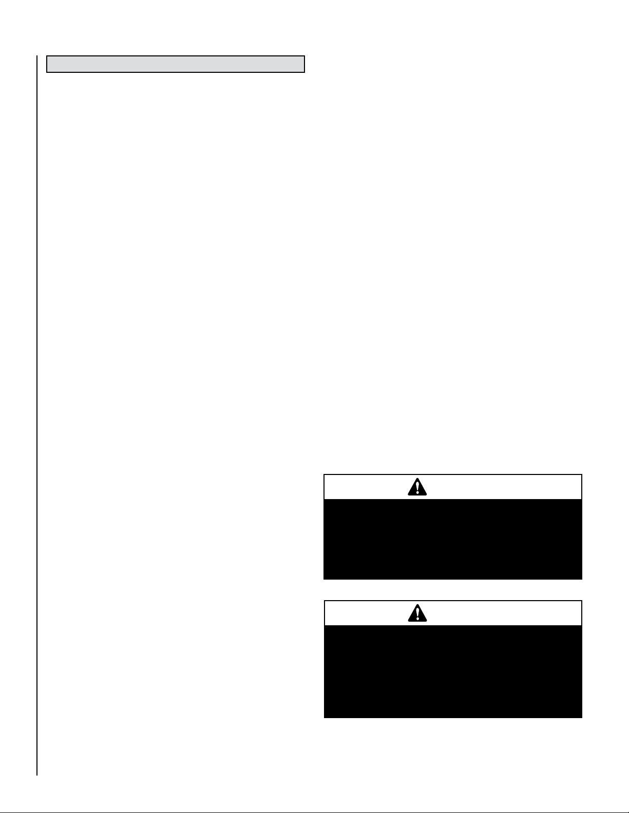
WARNING /
• HOT GLASS WILL
CAUSE BURNS.
• DO NOT TOUCH GLASS
UNTIL COOLED.
• NEVER ALLOW CHILDREN
TO TOUCH GLASS.
WARNING: If the information in these instructions is
not followed exactly, a fire or explosion may result
causing property damage, personal injury or death.
- Do not store or use gasoline or other flammable
vapors and liquids in the vicinity of this or any other
appliance.
- WHAT TO DO IF YOU SMELL GAS
• Do not try to light any appliance.
• Do not touch any electrical switch; do not use any
phone in your building.
• Immediately call your gas supplier from a neighbor’s phone. Follow the gas supplier’s instructions.
• If you cannot reach your gas supplier, call the fire
- Installation and service must be performed by a
qualified installer, service agency or the gas supplier.
department.
AVERTISSEMENT / AVISO
• UNE SURFACE VITRÉE CHAUDE PEUT
CAUSER DES BRÛLURES.
• LAISSER REFROIDIR LA SURFACE
VITRÉE AVANT D'Y TOUCHER.
• NE PERMETTEZ JAMAIS À UN ENFANT
DE TOUCHER LA SURFACE VITRÉE.
AVERTISSEMENT: Assurez-vous de bien suivre les instructions données dans cette notice pour réduire au minimum
le risque d’incindie ou d’explosion ou pour éviter tout
dommage matériel, toute blessure ou la mort.
- Ne pas entreposer ni utilizer d’essence ni d’autres vapeurs
ou liquides inflammables dans le voisinage de cet appareil
ou de tout autre appareil.
- QUE FAIRE SI VOUS SENTEZ UNE ODEUR DE GAZ:
• Ne pas tenter d’allumer d’appareil.
• Ne touchez à aucan interrupteur. Ne pas vous servir des
téléphones se trouvant dans le bâtiment où vous trouvez.
• Appelez immédiatement votre fournisseur de gaz depuis
un voisin. Suivez les instructions du fournisseur.
• Si vous ne pouvez rejoindre le fournisseur de gaz, appelez
le service des incindies.
- L’installation et l’entretien doivent être assurés par un
installateur ou un service d’entretien qualifié ou par le
fournisseur de gaz.
• EL VIDRIO CALIENTE
CAUSARÁ QUEMADURAS.
• USTED DEBE NUNCA
TOCAR EL VIDRIO CALIENTE.
• LOS NIÑOS DEBEN NUNCA
TOCAR EL VIDRIO.
Page 2
Thank you for your purchase. We appreciate your business!
Please carefully read and follow all instructions in this manual.
Pay special attention to all warnings and safety information.
Following these safety, care, and operation instructions will help
ensure many years of dependable and enjoyable service from
your fireplace.
•
FREE
severe burns and injuries by preventing direct contact
To receive your FREE SAFETY GUARD, call 1-800-786-7976
or visit www.lennox.com
TABLE OF CONTENTS
Safety and Your Fireplace . . . . . . 2-3
Important Safety Information . . . . . . 4
Appliance Installation, Service, and
Maintenance Notices . . . . . . . . . . . .5
Appliance Operation Notices . . . . . . . 5
Warranty Information . . . . . . . . . . . . . 5
General Information . . . . . . . . . . . . 5-6
Packaging List . . . . . . . . . . . . . . . . . . 7
Appliance Specifications . . . . . . . . . . 7
Unpacking the Appliance . . . . . . . . . . 7
Burn-in Period . . . . . . . . . . . . . . . . . . 7
Codes, Massachusetts and New York 7
Combustion And Ventilation Air . . . . . 8
Site Requirements . . . . . . . . . . . . . . . 9
Clearances . . . . . . . . . . . . . . . . . . . . . .9
Gas Supply Routes . . . . . . . . . . . . . . 10
Preparing The Appliance . . . . . . . . . 10
Mounting The Appliance . . . . . . . . . 11
SAFETY GUARD
The Lennox® SAFETY GUARD protects against
with the front glass surface of your fireplace.
(Lennox Hearth Products / Owner Resources)
Note: Safety Guards may not be available for some
older models, that are no longer in production.
Fitting the Surround Assembly . . . . . 12
Checking The Burner . . . . . . . . . . . . 13
Connecting A Gas Line . . . . . . . . . . . 13
Checking The Gas Connections . . . . 13
Gas Pressure Check . . . . . . . . . . . . . 14
Spark Gap . . . . . . . . . . . . . . . . . . . . 14
Briefing The Customer . . . . . . . . . . . 14
Servicing . . . . . . . . . . . . . . . . . . . . . 15
Catalysts . . . . . . . . . . . . . . . . . . . . . 16
Testing For Firebox Leakage . . . . . . . 16
Lighting Instructions & Turning Off
Appliance . . . . . . . . . . . . . . . . . . . 17
Troubleshooting Guide . . . . . . . . . . . 18
Replacement Parts List . . . . . . . . . . 19
Positioning of Field Assembled Parts 20
Accessories . . . . . . . . . . . . . . . . . . . 21
Gas Entry Point Dimensions . . . . . . 22
Product Reference Information . . . . 24
OFFER
•
Safety and
Your Fireplace
All parts of your Lennox
Hearth Products fireplace
get EXTREMELY HOT!
To prevent severe burns and injuries, install
a screen or physical barrier to prevent direct
contact with the glass.
To order a FREE Lennox® SAFETY GUARD
for your fireplace, see details at left.
Follow the safety instructions below
and be sure everyone in your household
understands this burn hazard:
• The surfaces on your fireplace get
EXTREMELY HOT!
• The glass on the front
of the fireplace reaches
EXTREMELY HIGH
temperatures and can cause severe
burns if touched.
• Keep children away from an operating
fireplace. Closely supervise children in
any room where a fireplace is operating
to prevent contact with glass.
• Keep clothing, furniture,
gasoline, and other
flammable liquids away
from the fireplace.
surfaces remain extremely hot.
Read Important Safety Information on
Page 4.
2
• Even after the gas is turned off, fireplace
Page 3
[FRENCH] [SPANISH]
La sécurité
et votre foyer
Toutes les parties de votre foyer
Lennox Hearth Products deviennent
EXTRÊMEMENT CHAUDES !
Afin d'éviter de vous brûler gravement ou de
vous blesser, installez une grille ou une barrière
physique pour empêcher tout contact direct
avec la vitre.
Pour commander un PANNEAU DE PROTECTION
Lennox
les détails dans la partie gauche.
Suivez les instructions de sécurité ci-dessous
et veillez à ce que tous les membres de votre
famille soient conscients du danger de
brûlure encouru :
• Les surfaces de votre foyer deviennent
EXTRÊMEMENT CHAUDES !
• La vitre située à l'avant du foyer
atteint des températures EXTRÊMEMENT
ÉLEVÉES et peut causer
de graves blessures en cas de contact.
• Tenez les enfants à l'écart du foyer
lorsqu'il fonctionne. Surveillez
attentivement
les enfants dans les pièces où un foyer
est utilisé afin d'éviter qu'ils ne soient
en contact avec la vitre.
• Tenez tous les vêtements, les meubles,
l'essence et tout autre liquide inflammable
à l'écart du foyer.
• Même après fermeture du gaz, les surfaces
du foyer restent extrêmement chaudes.
Lisez la Section Informations importantes
relatives à la sécurité, Page 4.
®
GRATUIT pour votre foyer, consultez
Seguridad y
su chimenea
¡Todas las partes de la chimenea
Lennox Hearth Products se ponen
MUY CALIENTES!
Instale una malla o barrera física para evitar
el contacto directo con el vidrio y prevenir
las quemaduras y lesiones graves.
Ver los detalles a la izquierda para ordenar
un Lennox
para su chimenea.
Siga las instrucciones de seguridad a
continuación y asegúrese de que todos
en su hogar sepan acerca de este peligro
de quemadura:
• ¡Las superficies de la chimenea se ponen
MUY CALIENTES!
• El vidrio delante de la chimenea alcanza
temperaturas EXTREMADAMENTE ALTAS y
puede causar quemaduras graves si se toca.
• Mantenga a los niños alejados de la
chimenea en funcionamiento. Supervise
en forma cercana a los niños en cualquier
cuarto donde haya una chimenea
funcionando para impedir el contacto
con el vidrio.
• Mantenga la ropa, mobiliario, gasolina
y otros líquidos inflamables alejados
de la chimenea.
• Aún después de haber apagado el gas,
las superficies de la chimenea permanecen
extremadamente calientes.
Lea la Información importante de seguridad
en la página 4.
®
SAFETY GUARD GRATIS
3
Page 4

Important Safety Information
L'information de sûreté importante
1. WARNING: Do not operate appliance with the glass front
removed, cracked or broken.
2. Do not use this appliance if any part has been under water.
Immediately call a qualified service technician to inspect
the appliance and to replace any part of the control system
and any gas control which has been under water.
3. Due to high temperatures, the appliance should be located
out of traffic and away from furniture and draperies.
4. Children and adults should be alerted to the hazards of
high surface temperature and should stay away to avoid
burns or clothing ignition.
5. Clothing or other flammable material should not be placed
on or near the appliance.
6. Young children should be carefully supervised when they
are in the same room as the appliance. Toddlers, young
children, and others may be susceptible to accidental
contact burns. A physical barrier is recommended if there
are at-risk individuals in the house. To restrict access to a
fireplace or stove, install an adjustable safety gate to keep
toddlers, young children, and other at-risk individuals out
of the room and away from hot surfaces.
7. Any safety screen or guard removed for servicing an
appliance must be replaced prior to operating the
appliance.
8. Installation and repair should be done by a qualified
service person. The appliance should be inspected
before use and at least annually by a professional service
person. More frequent cleaning may be required due to
excessive lint from carpeting, bedding material, et cetera.
It is imperative that control compartments, burners, and
circulating air passageways of the appliance be kept
clean. See maintenance instructions on Page 15.
1. AVERTISSEMENT. Ne pas utiliser l’appareil si le panneau frontal
en verre n’est pas en place, est craqué ou brisé.
2. Ne pas utiliser cet appareil s’il a été plongé, même partiellement,
dans l’eau. Appeler un technicien qualifié pour inspecter
l’appareil et remplacer toute partie du système de commande
et toute commande qui a été plongée dans l’eau.
3. En raison des températures élevées, l’appareil devrait être
installé dans un endroit où il y a peu de circulation et loin du
mobilier et des tentures.
4. Les enfants et les adultes devraient être informés des dangers
que posent les températures de surface élevées et se tenir à
distance afin d’éviter des brûlures ou que leurs vêtements ne
s’enflamment.
5. On ne devrait pas placer de vêtements ni d’autres matières
inflammables sur l’appareil ni à proximité.
6. Les jeunes enfants devraient être surveillés étroitement lorsqu’ils
se trouvent dans la même pièce que l’appareil. Les tout petits,
les jeunes enfants ou les adultes peuvent subir des brûlures s’ils
viennent en contact avec la surface chaude. Il est recommandé
d’installer une barrière physique si des personnes à risques
habitent la maison. Pour empêcher l’accès à un foyer ou à un
poêle, installez une barrière de sécurité ; cette mesure empêchera
les tout petits, les jeunes enfants et toute autre personne à risque
d’avoir accès à la pièce et aux surfaces chaudes.
7. Tout écran ou protecteur retiré pour permettre l’entretien de
l’appareil doit être remis en place avant de mettre l’appareil en
marche.
8. L’installation et la réparation devrait être confiées à un technicien
qualifié. L’appareil devrait faire l’objet d’une inspection par un
technicien professionnel avant d’être utilisé et au moins une
fois l’an par la suite. Des nettoyages plus fréquents peuvent
être nécessaires si les tapis, la literie, et cetera produisent
une quantité importante de poussière. Il est essentiel que les
compartiments abritant les commandes, les brûleurs et les
conduits de circulation d’air de l’appareil soient tenus propres.
Voyez les instructions d’entretien à la Page 15.
[SPANISH]
Información importante de seguridad
1. ADVERTENCIA: No opere el artefacto con el frente de vidrio quitado,
agrietado o roto.
2. No use este artefacto si alguna de sus partes ha estado bajo agua.
Llame de inmediato a un técnico de servicio calificado para que
inspeccione el artefacto y reemplace cualquier parte del sistema
de control y cualquier control de gas que haya estado bajo agua.
3. Debido a las altas temperaturas, el artefacto debe situarse fuera
de las áreas de tráfico y lejos del mobiliario y cortinas.
4. Se debe alertar a los niños y adultos sobre los peligros de
las altas temperaturas en la superficie y que se mantengan
alejados para evitar quemaduras o ignición de la ropa.
5. No debe colocarse ropa u otros materiales inflamables
sobre y cerca del artefacto.
4
6. Se debe supervisar de cerca a los niños cuando estén en el mismo
cuarto que el artefacto. Los niños pequeños, los jóvenes y otras
personas pueden ser susceptibles a quemaduras por contacto
accidental. Se recomienda instalar una barrera física si hay
personas en riesgo en la casa. Para restringir el acceso a una
chimenea o estufa, instale una puerta de seguridad ajustable
para mantener a los niños pequeños, jóvenes y otras personas
en riesgo fuera del cuarto y lejos de las superficies calientes.
7. Cualquier malla o resguardo de seguridad quitado para dar servicio
a un artefacto, debe reinstalarse antes de operar el artefacto.
8. Una persona de servicio competente debe realizar la instalación y
reparación. Una persona de servicio profesional debe inspeccionar
el artefacto antes de usar al menos una vez por año. Se puede
requerir limpieza más frecuente debido a la pelusa excesiva
del alfombrado, del material de cobijas, etc. Es imprescindible
mantener limpios los compartimientos de control, los quemadores
y los pasajes de circulación del aire del artefacto. Ver las
instrucciones de mantenimiento en la página 15.
Page 5

Appliance Installation,
Service, and Maintenance
Notices
WARNING: Improper installation,
adjustment, alteration, service or
maintenance can cause injury or
property damage. Refer to the owner’s
information manual provided with this
appliance. For assistance or additional
information consult a qualified installer,
service agency or the gas supplier.
Only trim kit(s) supplied by the manufacturer shall be used in the installation
of this appliance.
Any change to this appliance and/or
its operating controls is dangerous.
Improper installation or use of this
appliance can cause serious injury or
death from fire, burns, explosion or
carbon monoxide poisoning.
CARBON MONOXIDE POISONING:
Early signs of carbon monoxide
poisoning are similar to the flu with
headaches, dizziness and/or nausea. If
you have these signs, obtain fresh air
immediately. Turn off the gas supply to
the appliance and have it serviced by
a qualified professional, as it may not
be operating correctly. Some people
are more affected by carbon monoxide
than others, including pregnant women,
people with heart or lung disease or
anemia, those under the influence of
alcohol, and those at high altitudes.
Turn off gas to the fireplace and allow
it to cool before cleaning or servicing
the appliance.
Appliance Operation Notices
Do not operate appliance with the glass
front removed, cracked, or broken.
These fireplaces are unvented gas
appliances. Do not burn wood or other
material in these appliances.
This appliance is only for use with the
type of gas indicated on rating plate.
This appliance is Not convertible for
use with other gases.
These appliances are designed to
operate on natural gas or propane
gas only. The use of other fuels or
combinations of fuels will degrade the
performance of this system and may be
dangerous.
Provide adequate clearances around
air openings and adequate accessibility
clearance for service and proper
operation. Never obstruct the front
openings of the appliance.
These fireplaces are designed as
supplemental heaters. Therefore, it
is advisable to have an alternate primary heat source when installed in a
dwelling.
Warranty Information
Your gas appliance is covered by a limited
lifetime warranty. You will find a copy of
the warranty accompanying this manual.
Please read the warranty to be familiar
with its coverage.
Retain this manual. File it with your other
documents for future reference.
General Information
Do not build a wood fire. Do not
burn wood or other material in these
appliances.
Lennox
designed for use as a supplemental
heater. They are not intended for
continuous use as a primary heat
source.
Keep heater area clear and free from
combustible materials, gasoline and
other flammable vapors and liquids.
Hot! Do not touch! This appliance will
be hot during operation and will retain
heat for a while after shutting off the
appliance. Severe burns may result.
Carefully supervise children in the same
room as appliance.
®
vent-free appliances are
Failure to comply with the installation and
operating instructions provided will result
in an improperly installed and operating
appliance, voiding its warranty.
Do not attempt to alter or modify
the construction of the appliance or
its components. Any modification or
alteration may void the warranty,
certification, and listings of this unit.
5
Page 6
General Information
The appliance is designed to fit various types of situations as
listed in the installation requirements.
WARNING
This appliance is equipped for (natural or propane)
gas. Field conversion in not permitted.
WARNING
Failure to keep the primary air opening(s) of the
burner(s) clean may result in sooting and property
damage.
WARNING
Do not allow fans to blow directly into the fireplace.
Avoid any drafts that alter burner flame patterns.
WARNING
Check gas type: The gas supply must be the same
as stated on the appliance’s rating plate. If the gas
supply is different DO NOT install the appliance.
Contact your dealer for the correct model.
WARNING
Do not use a blower insert, heat exchanger insert
or other accessory not approved for use with this
heater.
WARNING
Due to the nature of this product the area around
the top of the appliance (i.e. the grill) gets very hot.
Care should be taken when operating the appliance.
IMPORTANT: Read and understand these instructions completely before installing or operating your
unvented room heater.
This appliance is factory set for operation on the gas type, and
at the pressure stated on the appliance rating plate.
Read all these instructions before commencing installation.
All instructions must be left in the possession of the user for
safekeeping.
Allow the heater to cool before servicing. Always shut off the
gas to the heater while performing service work.
The installation must conform with local codes or, in the
absence of local codes with the National Fuel Gas Code,
ANSI Z223.1/NFPA 54-latest edition.
The appliance and its appliance main gas valve must be
disconnected from the gas supply piping system during any
pressure testing of that system at test pressures in excess
of 1/2 psi (3.5 kPa).
The appliance must be isolated from the gas supply piping
system by closing its equipment shut-off valve during any
pressure testing of the gas supply piping system at test pressures equal to or less than 1/2 psi (3.5 kPa).
Input ratings are shown in BTU per hour and are for elevations
up to 4,500 feet. Do not install this heater at an elevation
above 4,500 feet if the gas supply has not been derated for
that elevation. Consult your local gas supplier. (For operation
at elevations above 4,500 feet, equipment ratings shall be
reduced at the rate of 4 percent for each 1,000 feet above
4,500 feet before selecting appropriately sized equipment).
When installing any vent-free appliance at elevations above
4500 feet, nuisance pilot outages may occur.
Ensure that the heater is clean when operating. Excessive
dust accumulation on the burner will increase the amount
of carbon monoxide formation and could lead to carbon
monoxide poisoning and/or death.
This appliance is a high efficiency, unvented, flame effect gas
heater. It provides radiant and convected warmth both efficiently
and safely utilizing the latest type catalytic convertor burner
technology. The appliance does not require a flue system of any
type as the catalytic converter cleans the flue products to provide
a complete combustion system, which is intrinsically safe.
These heaters are fitted with a specially designed pilot utilizing an
oxygen depletion sensor (ODS) which responds to the amount
of oxygen available in the room and shuts the heater off before
the oxygen level drops below 18%. It must not be adjusted or
put out of operation. If replaced then manufacturers original
parts must be used. The pilot can be relit only when fresh air is
available. Refer to the Combustion and Ventilation Air section.
6
This appliance is intended for supplemental heating. If the
appliance is used in a room as the sole source of heat, then
condensation may occur on colder surfaces within the room.
Maintain minimum clearances.
Do not install the appliance in a sleeping room or bathroom.
Do not place any objects on top of the appliance.
Page 7
PACKAGING LIST
BURN-IN PERIOD
Quantity Description
Fireplace
1 Firebox, burner assembly and outer case (wrap)
1 Installation and Operation Manual
1 Warranty Certificate
1 Screw and wall plug pack
1 Rubber grommet
Surround Assembly
(required - sold separately. see Page 21 for ordering information)
1 Surround Assembly
1 Installation Instruction Sheet
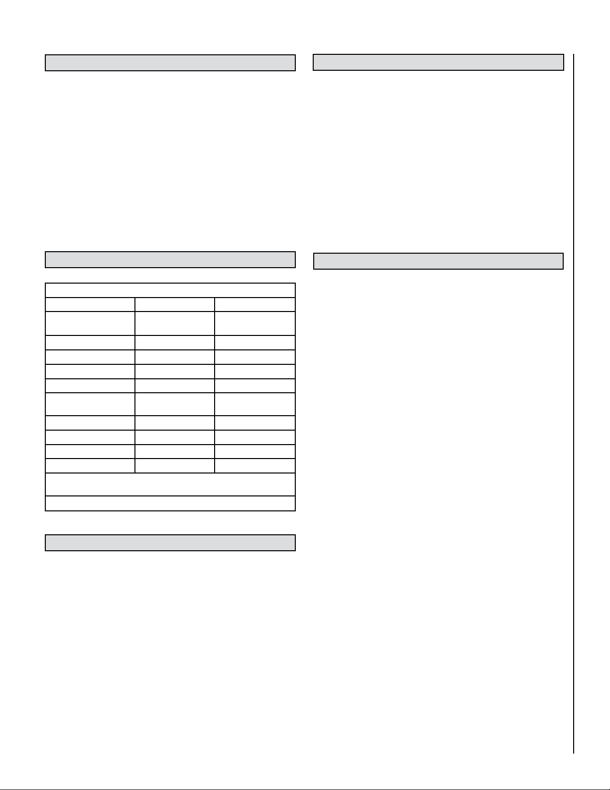
APPLIANCE SPECIFICATIONS
X-Fires™ Wide Screen
Gas Type Natural Gas Propane Gas
Gas inlet pressure
Max.
Min.
Regulator Pressure Setting 5” w.c. 10” w.c.
Max Energy Input 11,950 BTU/hour 10,235 BTU/hour
Min Energy Input 6,820 BTU/hour 6,820 BTU/hour
Pilot Energy Input 560 BTU/hour 560 BTU/hour
Main burner flow restrictor
(burner orifice)
Oxypilot SIT/Bray 9082 SIT/Bray 9284
Gas Inlet Connection 3/8” NPT at regulator 3/8” NPT at regulator
Ignition Double Piezo spark Double Piezo spark
Spark Gap 1/8” - 3/16” 1/8” - 3/16”
Please see Data Plate affixed to appliance for current data. This appliance is for use
only with the gas type, and at the pressure stated on the appliance Data Plate.
10.5” w.c.
6” w.c.
1.55 mm (0.063”) 1.03mm (0.042”)
13” w.c.
11” w.c.
Table 1
UNPACKING THE APPLIANCE
On initial light up of a new appliance, the ‘newness’ will burn off within
the first few hours of operation. During this period some smoke may be
emitted from outlet grill, this should be no cause for concern. Accordingly, the room should be well ventilated with all windows and doors
open during this period.
Depending on your use, the burn-in period may take a few hours or a few
days. Also if you have a sensitive sense of smell you may notice slight
odors during operating after the burn-in period is over.
KEEP YOUR HOUSE WELL VENTILATED DURING THE BURN-IN PERIOD.
THE ODOR AND HAZE EMITTED DURING THE BURN-IN PERIOD CAN BE
QUITE NOTICEABLE AND MAY SET OFF A SMOKE DETECTOR. MAKE
SURE SMOKE DETECTORS ARE NOT TOO CLOSE TO THE FIREBOX
(CHECK WITH YOUR LOCAL CODE FOR ALLOWABLE DISTANCES).
CODES
Adhere to all local codes or in their absence the latest edition of The
National Fuel Gas Code ANSI Z223.1 / NFPA 54 - latest edition which can
be obtained from The American National Standards Institute, Inc. (1430
Broadway, New York, NY, 10018) or National Fire Protection Association,
Inc. (Batterymarch Park, Quincy, MA, 02269).
Seller of unvented propane or natural gas fired supplemental room
heaters in the Commonwealth of Massachusetts shall provide to each
purchaser a copy of 527 CMR 30 upon sale of the unit.
This Lennox Hearth Products Unvented Gas Room Heater is certified by
OMNI-Test Laboratories, Inc to ANSI Z21.11.2 standard.
Massachusetts Requirements
These fireplaces are approved for installation in the US state of Massachusetts if the following additional requirements are met:
• Unvented Room Heaters shall be installed in accordance with 527
CMR and 248 CMR:
• Installation and repair must be done by a plumber or gas fitter licensed
in the Commonwealth of Massachusetts
• The flexible gas line connector used shall not exceed 36 inches (92
centimeters) in length.
• The individual manual shut-off must be a T-handle type valve.
• Vent-Free appliances may NOT be installed in bedrooms or bathrooms.
• A working smoke detector must be installed in the area where ventfree appliances are installed.
Remove the straps and the top lid of the outer packaging, remove any
instructions or fixing kits. Read ALL these instructions before continuing
to unpack or install this appliance.
Lift off the remaining packaging components.
Check that the components supplied with the packaging list on Page 7.
Please dispose of all the packaging materials at your local recycling center.
Seller of unvented propane or natural gas-fired supplemental room heaters
shall provide to each purchaser a copy of 527 CMR 30 upon sale of the unit.
New York:
These fireplaces are approved for installation in the US state of New York,
but not in New York City.
7
Page 8
COMBUSTION AND VENTILATION AIR
This heater shall not be installed in a confined space or unusually tight
construction unless provisions are provided for adequate combustion and
ventilation air. The heater may be located in unusually tight construction
provided the space is unconfined, or if confined, is provided with two
permanent openings communicating directly with an additional room(s)
of sufficient volume so that the combined volume of all connected spaces
meets the criteria for an unconfined space, (National Fuel Gas Code
NFPA 54 / ANSI Z223.1 - latest edition, section on Air for Combustion
and Ventilation. Generally 50 ft
appliances in the space.
The National Fuel Gas Code, ANSI Z223.1/NFPA 54, defines a confined
space as a space whose volume is less than 50 ft
3
(4.8 m
per kW) of the aggregate input rating of all appliances installed
in that space and an unconfined space as a space whose volume is not
less than 50 ft
rating of all appliances installed in that space.
Rooms communicating directly with the space in which the appliances
are installed, through openings not furnished with doors, are considered
a part of the unconfined space.
Unusually tight construction is defined as construction where:
a. Wall and ceilings exposed to the outside atmosphere have a continu-
ous water vapor retarder with a rating of one perm (6 X 10-11 kg per
pa-sec-m
b. Weather stripping has been added on operable windows and doors;
and
c. Caulking or sealants are applied to areas such as joints around window
and door frames, between sole plates and floors, between wall ceiling
joints, between wall panels, at penetrations for plumbing, electrical,
and gas lines, and at other openings.
Use the following equations to determine if you have a confined or
unconfined space.
3
per 1,000 BTU/Hr (4.8 m3 per kW) of the aggregate input
2
) or less with openings gasketed or sealed;
3
per 1,000 BTU input of all operating
3
per 1,000 BTU/Hr
Example:
Vent-free heater #1 9,000 BTU/Hr
Vent-free heater #2 23,000 BTU/Hr
Gas appliance #1 35,000 BTU/Hr
(water heater)
Total = 67,000 BTU/Hr
* Do not include direct-vent gas appliances. Direct-vent is sealed com-
bustion and draws combustion air from the outdoors.
4. Compare the maximum BTU/Hr the space can support with the actual
amount of BTU/Hr used.
_______ BTU/Hr (max. the space can support)
_______ BTU/Hr (actual amount of BTU/Hr used)
Example:
61,440 BTU/Hr (max. the space can support)
67,000 BTU/Hr (actual amount of BTU/Hr used)
The space in the previous example is a confined space because the actual
BTU/Hr used is more than the maximum BTU/Hr the space can support.
You must provide additional fresh air.
Your options are:
a. Rework equations adding the space of adjoining room(s). If the extra
volume provides an unconfined space, then remove door or add
ventilation grills between rooms. Refer to National Fuel Gas Code,
ANSI Z223.1/NFPA 54-latest edition, section "Air for Combustion and
Ventilation".
b. Vent room directly to the outdoors. Refer to National Fuel Gas Code,
ANSI Z223.1/NFPA 54-latest edition, section "Air for Combustion and
Ventilation".
c. Install a lower BTU/Hr heater to make the area an unconfined space.
If the actual BTU/Hr used is less than the maximum BTU/Hr the space
can support, then the space is an unconfined space. You will need no
additional fresh air ventilation for an unconfined space.
3
3
)/ 50 ft3 =
3
.
3
1. Determine the volume of space — ft
Length x Width x Height = _____ ft
(Include adjoining rooms with doorless passageways or ventilation
grills between rooms).
Example: 24' (L) x 16' (W) x 8' (H) = 3072 ft
2. Divide the volume of space by 50 ft3 to determine the maximum BTU/Hr
the space can support.
______ (volume of space – ft
(Maximum BTU/Hr the space can support)
Example: 3072 ft
or 61,440 BTU/Hr the space can support.
3. Add the BTU/Hr of all the fuel burning appliances in the space.
Vent-Free heater _______ BTU/Hr
Gas appliance #1* _______ BTU/Hr
Gas appliance #2 + _______ BTU/Hr
Gas appliance #3 + _______ BTU/Hr
Total = _______ BTU/Hr
8
3
/ 50 ft3 = 61.44
WARNING
If the area in which the heater may be operated does
not meet the required volume for indoor combustion
air, combustion and ventilation air shall be provided
by one of the methods described in the National Fuel
Gas Code, ANSI Z223.1/NFPA 54, the International
Fuel Gas Code or local applicable codes.
WARNING
If the area in which the heater may be operated is
smaller than that defined as an unconfined space
or if the building is of unusually tight construction,
provide adequate combustion and ventilation air by
one of the methods described in the national fuel
gas code, ANSI Z223.1/NFPA 54, Air for Combustion
and Ventilation Or applicable local codes.
Page 9

SITE REQUIREMENTS
CLEARANCES TO COMBUSTIBLE MATERIALS
This appliance is designed to be wall-hung. Do not recess any part of
the appliance into the wall.
This appliance may be installed in any room in a home except bedrooms
or bathrooms - or areas where large amounts of steam are likely to be
generated.
It should be noted that heaters create warm air currents. These currents
move heat to wall surfaces next to the heater. Installing the heater next
to vinyl or cloth wall coverings or operating the heater where impurities in the air (such as tobacco smoke or candle smoke) exist, may
discolor walls.
Installation in living rooms is common, however other rooms such as
kitchens, dining rooms and hallways are permitted, providing a suitable
gas supply is available, and rooms sizing and ventilation requirements
are strictly adhered to (see Page 8).
The appliance is designed to be versatile, and as such will operate correctly
when exposed to normal gentle drafts experienced within the home. It is
not recommended, however that the appliance be installed in areas where
it is likely to be exposed to persistent strong drafts, that may be generated
by outside doors or windows, air vents etc. It is recommended that the
appliance should not be installed within 20" of any air vent.
CAUTION
The back of the appliance may be installed directly
onto a combustible wall or non-combustible wall,
providing the area behind the appliance is flat and
does not interfere with the various vent holes in the
back panel of the appliance.
CLEARANCES TO NON-COMBUSTIBLES
Non-combustible surfaces are defined as brick, metal, marble, concrete
etc. and also a number of man-made materials impervious to flame. If in
doubt refer to the material manufacturer for further information before
proceeding with installation.
Combustible materials are defined as wood, fabrics, or other materials
likely to combust if exposed to flame. Generally, any material, which is
likely to discolor, melt or misshape when exposed to moderate heat,
should be considered as a combustible material or surface.
Clearance to the sides of the appliance are 4” but curtains, drapes and
other fabrics are not permitted within a distance of 20” of the appliance
sides. No such materials are permitted directly above the appliance
regardless of distance.
The minimum clearance to the ceiling above the appliance is 32” measured
from the top of the appliance glass panel.
Combustible materials should not be positioned directly in front of the
appliance within a distance of 40”.
Under no circumstances should any electrical equipment e.g. plasma
screen TV sets etc. be positioned on the wall above the appliance. The
appliance is designed to be wall mounted alone and not in conjunction
with any type of combustible fire surround.
No combustible shelves should be positioned on the wall above the
appliance.
It should be established that any mirrors or picture frames etc. to be
positioned on the wall above the appliance are able to withstand prolonged exposure to moderate heat and moisture before proceeding with
their installation.
The wall must be structurally sound and constructed from a material
capable of withstanding moderate heat. Finished plaster, conventional
wall paper and dry-lined plasterboard are examples of suitable materials. Materials such as flock, blown vinyl and embossed paper which are
sensitive to even small amounts of heat should be avoided as scorching
and or discoloration may occur over time.
If the appliance is to be mounted on a dry-lined wall or a timber framed
construction wall then the integrity and ability of the wall to carry the
weight of the appliance must be confirmed. It is important in these
circumstances that any vapor control barrier is not damaged, and that
any structural members of the house frame are not damaged.
Clearances to the sides of the appliance are 4”. Clearance to the front
of the appliance is 20”.
The appliance may be installed with or without a non-combustible hearth.
If a hearth is fitted, the size and design may be as desired.
A non-combustible shelf of any depth may be positioned above the appliance provided it is no closer than 16” from the top of the appliance glass
panel and the wall above the appliance is non-combustible.
The appliance may be positioned as close to a solid floor (i.e. stone,
wooden laminate etc.) as the particular design of fire frame permits,
however it is not permitted to install the appliance within 4” of carpet,
rugs or fabric materials of any kind. This dimension is measured vertically to the bottom of the appliance frame.
9
Page 10

GAS SUPPLY ROUTES
IMPORTANT NOTE: All gas piping must be done by
a licensed plumber or gas fitter and must conform
to the requirements of the National Fuel Gas Code
NFPA 54 / ANSI Z223.1 - latest edition.
Gas connection: The heater gas inlet connection is
3/8” NPT at the regulator, located below the burner,
in the right hand side of the heater. There are four
possible entry points for the gas supply pipe-work
to enter the appliance firebox. These entry points are
‘knock out’ type holes (shown in Figure 1).
NOTE: See Page 22 for gas line entry
point dimensions.
Wall Mounting Plate
Firebox
Figure 2
Figure 1 - Gas Supply Entry Points
Non-concealed gas connections may be made
using the entry points on the base of the firebox.
A concealed gas connection may be made using
the knockout hole in the center back of the firebox.
Select the most appropriate entry point and knock
out the relevant hole.
No more than 59" of 1/4" diameter pipe must be used
to avoid unnecessary pressure drops.
If a concealed gas con nection is to be made, the
supply pipe should always be sleeved through walls
and floors using the shortest possi ble route.
For concealed supply pipe routing, pipes must
(where possible) be ver tical and providing there is
sufficient wall thick ness available, they should be
placed in pipe chases. Horizontal pipe runs should
be avoided where possible. Prior to chasing a
solid wall, an inspection should be made to note
the proximity of any cables/sockets outlets which
may already be buried. Pipes must be secured using
suitable clips and protected against corrosion.
Ideally factory finished protected pipe-work and
fittings should be used. Joints should be kept to
a minimum and compression fittings must not be
used. The pipe-work installation must be tested for
soundness before any protection is applied and/or
the pipe-work and fittings are buried.
PREPARING THE APPLIANCE
Remove the wall mounting plate from the back of the appliance firebox by removing the two
retaining wing nuts (indicated by arrows in Figure 2) from the retaining studs that protrude
into the lower part of the main firebox.
10 NOTE: DIAGRAMS & ILLUSTRATIONS ARE NOT TO SCALE
Page 11

MOUNTING THE APPLIANCE
After having selected the final mounting position of the appliance, tak ing
into account the site requirements as specified in these instructions,
the integrity of the wall, and the feasibility of the proposed supply pipe
routing, the firebox of appliance may be secured to the wall.
Incorrect installation can cause the appliance to fall from the wall and
cause injury. Do not block the ventilation holes of the appliance. The
wall onto which the appliance is installed must be flat. Install only on a
vertical surface. Avoid sloped surfaces. Installation onto anything other
than a vertical wall may result in fire, damage or injury.
A full size fitting template is supplied to assist with wall mounting (see
Figure 3).
WARNING
The wall where the appliance is to be installed must
be capable of long-term support of the total load of
the appliance. Measures should also be taken to
ensure sufficient strength to withstand the force of
earthquakes, vibration and other external forces.
To ensure customer safety, be sure to design the installation so that the
strength of both the wall and any wall fixings used are sufficient. Lennox
Hearth Products assumes no responsibility for injuries and damages
that may occur due to improper installation or handling.
The appliance should not be installed until all dry wall sanding and wall
painting has been completed.
POSITION SPIRIT LEVEL ALONG THIS EDGE TO LEVEL TEMPLATE BEFORE MARKING OUT WALL
COLOQUE EL NIVEL SOBRE ESTE BORDE PARA NIVELAR LA PLANTILLA ANTES DE MARCAR LA PARED
FIXING POINTS
PIERCE TEMPLATE TO MARK HOLE POSITION ON WALL X 4
PERFORE LA PLANTILLA PARA MARCAR LA POSICION DE LOS 4 TALADROS EN LA PARED
PUNTOS DE SUJECION
If the heater is to be installed on a studded wall with conventional 16”
stud spacing then a wall mounting plate is supplied to enable this. NOTE:
THIS APPLIANCE MUST BE SECURED DIRECTLY TO THE STUDS AT THE
FIXING POINTS THAT ARE 16" DISTANCE (see template below). First
locate the studs and using suitable fixings, screw the mounting plate to
the wall via the four mounting holes. The heater may then be hung onto
the mounting plate. The bottom of the heater may be secured onto the
lower mounting studs using the wing-nuts or the hex nuts provided.
Mark the positions shown as “Fixing Points” on the wall. If the appliance
is to be mounted on the inner leaf of a conventional cavity wall, or a solid
wall, drill four holes using a 5/16" masonry bit, to a depth of 1-11/16".
Insert the fiber wall plugs provided.
If the appliance is to be mounted on a dry lined wall or a timber framed
construction wall then special cavity screw fixings will be required
which are not supplied with this product. These should be constructed
from metal and not plastic.
If a concealed gas connection is to be made ensure the gas supply pipe
is in it’s final position and can enter the appliance in the correct position
when the appliance is hung on the wall.
/2” (368.5mm)14
1
14
WARNING
CLEARANCES FROMCOMBUSTIBLEMATERIALS
The following clearances must be maintained at all times.
Failure to do so may result in the risk of a fire.
For full information refer to the instruction manual
provided with the heater.
Clearance to combustible ceiling
32” measured from top of appliance
glass panel
Clearance in
Clearance to
front of
combustible
heater 20”
sidewalls 4”
IMPORTANT : Fabrics, curtains and drapes are not
permited above the heater at any distance and within
20” of the heater sides. No combustible shelves of any
size are permitted above the heater.
ESPACIO LIBRE HASTAMATERIALES COMBUSTIBLES
Deben mantenerse en todo momento los siguientes espacios
libres. El no hacerlo puede causar un riesgo de incendio.
Consulte el manual de instrucciones suministrado con este
aparato para obtener información completa.
IMPORTANTE: No se permite la colocación de telas, cortinas y
similares por encima del calentador a cualquier distancia, ni a
una distancia de 20” de los laterales del calentador. No se
permiten estantes combustibles de cualquier tamaño por
encima del calentador.
F860488 - ISSUE A - PRW
Note : Zero clearance from bottom of heater frame
required for hard combustible floors. Minimum 4”
clearance required to rugs or any fabric floor
coverings. REFER TO INSTRUCTION MANUAL
ADVERTENCIA
El espacio de 32” hasta un techo
combustible se mide desde el borde
superior del panel de vidrio del aparato
Espacio libre
delante del
calentador 20”
Nota: No se requiere espacio libre desde el borde inferior del
marco del calentador en caso de pisos combustibles duros.
Se requiere un espacio mínimo de 4” entre el calentador y
cualquier alfombra, moqueta o revestimiento de suelo de
tela. CONSULTE EL MANUAL DE INSTRUCCIONES.
(both sides)
F860041/A
Espacio hasta
paredeslaterales
combustibles
4” (ambos lados)
F860041/A
/2” (368.5mm)
1
/8”
1
1
(29mm)
Figure 3 - Wall Fixing Template
8 3/4” (223mm) 8 3/4” (223mm)7 3/16” (183mm) 7 3/16” (183mm)
PLANTILLA PARA LA INSTALACION DE CHIMENEAS DE PARED SIN SALIDA DE HUMOS
16” (406mm)
IMPORTANT
THIS APPLIANCE IS TO BE WALL HUNG ONLY.
DO NOT RECESS OR INSET ANY PART OF THE APPLIANCE.
THIS TEMPLATE IS FOR THE MARKING OF FIXING POINTS ONLY.
DO NOT INSTALL THE APPLIANCE WITH THIS TEMPLATE IN PLACE.
X-FIRES WIDESCREEN
WALL MOUNTED VENT FREE FITTING TEMPLATE
CENTRE LINE
LINEA DE CENTRO
™
16” (406mm)
ESTE APARATO UNICAMENTE DEBE SER COLGADO EN UNA PARED.
ESTA PLANTILLA SIRVE UNICAMENTE PARA MARCAR LOS PUNTOS DE FIJACION.
CONCEALED
GAS INLET
ENTRADA DE
GAS OCULTA
IMPORTANTE
NO EMPOTRE NINGUN ELEMENTO DE ESTE APARATO.
RETIRE LA PLANTILLA ANTES DE COLOCAR LE APARATO.
FIREBOX OUTLINE
CONTORNO DE LA CAMARA DE COMBUSTION
APPLIANCE OUTLINE CONTORNO DE LA APARATO
NOTE: DIAGRAMS & ILLUSTRATIONS ARE NOT TO SCALE
11
Page 12

It is recommended that the burner height, where possible, should
be approximately 4 ft. from the floor. This will give the best viewing
position. When selecting the height, ensure that the clearance to the
ceiling is 32" minimum, as specified on Page 9.
After selecting the final mounting position of the appliance, taking
into account the site requirements as specified in section - Site
Requirements of these instructions, the integrity of the wall, and the
feasibility of the proposed supply pipe routing, the firebox of the
appliance may be secured to the wall.
Due to the weight of the front surround assembly, it is possible to fasten
the outer casing to the wall in up to nine positions, depending on the
strength/condition of the wall. If in doubt always use extra fixings!
Use a bubble level to ensure that the outer casing is level at all times
during installation.
Insert the screws into two of the upper holes, leaving 3/16" protruding
from the wall. Temporarily hang the outer casing on the wall, and mark
any additional fixing points as required. If the appliance is to be fitted
to a lightly colored wall, it is advantageous to paint this wall area with
black or dark paint in the vicinity of the lower rectangular slots on the
outer casing. This will mask the wall when viewed from the front of the
appliance. Ensure paint is fully dry before mounting the appliance. Use
the outer casing as a template to mark this area on the wall. Remove
the outer casing from the wall and drill holes for the additional fixing
points as required. Insert either wall plugs or cavity screw fixings as
required. Re-position the outer casing on the wall and using a bubble
level to check the casing is square and level, tighten all of the fixing
screws fully.
FITTING THE SURROUND ASSEMBLY
Due to the weight of the frame assembly, it is recommended to seek
assistance for this operation.
The frame assembly will be supported by keyhole slots by four M6
screws which protrude from the front of the outer casing (see Figure
5). Ensure each screw is unscrewed approximately one turn from the
fully screwed in position in order to create a 1/16" gap (shown). Hang
the surround assembly onto the outer casing, starting with the two
bottom fixings, ensuring that the corresponding keyhole shaped holes
engage the screw heads fully.
Heat Shield
Now, with the outer casing fixed to the wall, the main firebox can be
secured in position. The firebox is held on the outer casing using four
studs and two normal nuts (upper fixings) and two wing nuts (lower
fixings). Make sure that the upper nuts are unscrewed approximately
one turn from the fully tightened position in order to create a 1/16" gap
as shown in Figure 4. The firebox may now be hung onto the top studs,
and then pushed onto the lower studs so that the lower studs protrude
through the lower fixing holes in the back panel of the firebox.
Next, re-fit the grill, the indicator bracket and the control knob and
spindle, and secure in position using the correct fixing screws (re-fitting
is the opposite of removal as detailed in these instructions).
1/16"
IMPORTANT NOTE: Ensure that the
surround is positioned with the
heat shield on top as shown.
Figure 5
Figure 4
12 NOTE: DIAGRAMS & ILLUSTRATIONS ARE NOT TO SCALE
Page 13

CHECKING THE BURNER
There are no imitation fuel bed components, such as logs or rocks,
to install. The appliance features a ribbon burner which is designed to
produce a continuous band of flame over its length. The burner should
be visually inspected to ensure it is free from any foreign matter. If it is
necessary to clean or dust off the burner then the glass door should be
removed by removal of the four retaining screws. Re-fit the glass door
after cleaning or inspection, ensuring a good seal.
CONNECTING A GAS LINE
An ANSI approved manual shut-off valve and union must be installed
upstream of the heater within the fireplace cavity when rigid pipe is
used. Ensure that a sediment trap is installed upstream of the heater
(Figure 6) within the structure’s piping system to prevent moisture and
contaminants from passing through the pipe to the heater controls and
burner. Failure to do so could prevent the heater from operating reliably.
The heater gas inlet connection is 3/8” NPT at the regulator, located
below the burner, in the right hand side of the heater. When tightening
up the joint to the regulator hold the regulator securely with a wrench
to prevent the regulator from moving.
NOTE: See Page 22 for gas line entry point dimensions.
WARNING
Connecting directly to a unregulated propane
(L.P.G.) tank may cause an explosion.
IMPORTANT
Hold heater regulator with a wrench to prevent
movement when connecting to inlet piping.
A qualified gas appliance installer must connect the gas room heater to
the gas supply. Consult all local codes.
The installer must provide an ANSI approved manual shut off valve, flex
connector and 3/8" NPT fitting. A flex gas line kit with shut-off valve is
available (see Page 19 for ordering information).
Route gas line using techniques and materials prescribed by local
and/or national codes. Only use pipe of 1/2" or greater size to allow full
gas volume to the gas fireplace. Undue pressure loss will occur if the
pipe is too small.
An external regulator must be used on all propane (L.P.G.) heaters, in
addition to the regulator fitted to the heater, to reduce the supply tank
pressure to 13" w.c. (maximum).
CHECKING THE GAS CONNECTIONS
WARNING
Never use an open flame to check for leaks.
Turn on gas supply and test for gas leaks using a gas leak test solution
(also referred to as bubble leak solution).
NOTE: Using a soapy water solution (50% dish soap, 50% water) is
an effective leak test solution, but it is not recommended, because the
soap residue that is left on the pipes/fittings can result in corrosion
over time.
A. Light the appliance (refer to the lighting instructions label in the con trol
compartment or on Page 17).
B. Brush all joints and connections with the gas leak test solution to
check for leaks. If bubbles are formed, or gas odor is detected, turn
the gas control knob (off/pilot/on) to the “OFF” position. Either tighten
or refasten the leaking connection, then retest as described above.
C. When the gas lines are tested and leak free, be sure to rinse off the
leak testing solution.
D. Observe the individual tongues of flame on the burner. Make sure all
ports are open and producing flame evenly across the burner. If any
ports are blocked, or partially blocked, clean out the ports.
Figure 6
Regulator
Fireplace or
Firebox Wall
3"
Union
Fireplace or
Firebox Wall
Sediment
Trap
Manual
Shut-Off
Valve
Wall
Shut-Off
Key
Down
NOTE: DIAGRAMS & ILLUSTRATIONS ARE NOT TO SCALE
13
Page 14

17.0 GAS PRESSURE CHECK
SPARK GAP
The heater regulator controls the burner pressure which should be
checked at the pressure test point located on the appliance inlet pipe.
The appliance inlet pipe runs between the regulator and the gas valve
and the test point is located next to the regulator as shown in Figure 7a.
WARNING
Turn off the gas supply before removing the pressure
test point screw.
The test point is situated before the appliance gas valve so it will be
necessary to turn off the gas supply before removing the test point
screw. Connect the pressure gauge.
The gap between the spark electrode and the pilot should be 1/8” to
3/16” to produce a good spark. There should be no need to adjust this
(DO NOT ATTEMPT TO ADJUST THE GAP). If under any circumstances
the piezo electric spark fails, the pilot cannot be lit manually.
Adjustment to the
pilot is Not allowed
Figure 8 - Proper Spark Gap
1/8" to 3/16" Spark Gap
BRIEFING THE CUSTOMER
Figure 7a - Remove test point screw
Turn on the gas supply and light the heater. Turn the control to the high
flame setting and check the pressure. The pressure regulator on manual
models is preset and locked to avoid tampering. If the pressure is not as
specified in Table 1 on Page 7, replace the regulator with P/N H6063
for Natural Gas units and H7001 for Propane Gas units. Replace the test
point screw ensuring no gas leaks.
WARNING
Do not add logs or ornaments such as pine cones,
vermiculite or rock wool. Using these added items
can cause sooting.
All instructions must be left in the possession of the user for safekeeping.
If at all possible, show the customer how to light and control the appliance and show the customer how to remove and replace the surround
assembly and glass door assembly.
After commissioning the appliance, the customer should be instructed
on the safe use of the appliance and the need for regular servicing.
Frequency of service depends on usage, but MUST be carried out
at least once annually. Advise that cleaning of the appliance may be
achieved when the fire is cold using a damp cloth and mild detergent
on most surfaces.
Advise that the fireplace will emit a "newness" smell for a time after
initial commissioning and that extra ventilation may be needed during
this time. Recommend that a guard be used for the protection of the
young, pets, the elderly and the infirm.
Advise the user to never place any objects on top of the appliance or
obstruction this area in any way.
A periodic visual check of the pilot flame and the burner flame should
be carried out.
Figure 7b - Check regulator pressure
14 NOTE: DIAGRAMS & ILLUSTRATIONS ARE NOT TO SCALE
Page 15

SERVICING
WARNING
Turn off the appliance and allow to cool before
cleaning. Verify proper operation after servicing.
WARNING
Any change to this heater or its controls can be
dangerous.
WARNING
You must keep control areas, burners and circulating air passageways of appliance clean. Failure to
keep the primary air opening(s) of the burner clear
may result in sooting and property damage. Inspect
these areas of appliance before each use. Have
appliance inspected yearly by a qualified service
person. Appliance may need more frequent cleaning due to excessive lint form carpeting, bedding
material, etc.
7. Remove the burner unit, strip off the burner pipes and clean thoroughly.
8. Clean the in-line restrictor, pilot assembly and the burner tube. Clean
the exterior of the pilot assembly with a soft brush and blow through
the flame ports on the pilot head. Check the aeration holes are free
from lint or dirt. Do not attempt to remove the pilot injector as this
can cause damage. The pilot assembly is a non-serviceable item and
should not be taken apart. Aeration holes must be clear internally for
proper operation. NEVER MODIFY OR BEND THE THERMOCOUPLE
TO MAKE THE PILOT STAY LIT. Modifications are dangerous and can
have serious unseen effects on safety. If the pilot will not stay lit there
is a problem with dirt, the gas supply to it, or the thermocouple needs
replacement.
9. Re-assemble components.
10. Re-connect the gas supply. Turn on the gas supply and perform a gas
leak test using gas leak test solution. Check pilot and burner for good
ignition.
11. Refit the valve cover and retaining screws.
12. Refit the glass door assembly (see section - Positioning of Field
Assembled Parts).
13. Refit the surround assembly as described in section - Fitting the
Surround Assembly.
14. Check the purpose provided ventilation is unobstructed.
15. Light the fireplace and test setting pressures.
16. Check safe operation of the appliance.
NOTES:
• The gas valve is a non-serviceable item. If it needs replacement,
replace the burner assembly. Replacement must be original manufacturers parts.
WARNING
No adjustments are to be made to the ODS pilot
system. Tampering with this system can be extremely
hazardous.
The appliance should be checked on an annual basis to ensure it is working safely and that there is no excessive build up of soot. The frequency
of service will depend on usage, but MUST be carried out at least once
annually. Servicing must be carried out by a qualified person, such as
a NFI certified technician.
Turn off the fireplace at the gas supply. Ensure that the fireplace
is fully cold before attempting service. A suggested procedure for
servicing is detailed as follows;
1. Lay out the dustsheet and tools.
2. Remove the granite or limestone surround assembly as described
in section - Fitting the Surround Assembly, only in reverse.
3. Remove the glass door assembly (4 screws) and clean carefully.
Remove the valve cover plate (4 screws).
4. Inspect the burner and the catalysts (see section - Catalysts) and
clean if necessary with a soft brush. Ensure there are no defects or
obstructions that may prevent the satisfactory flow of combustion
products through the catalysts.
5. Disconnect the gas supply. IMPORTANT NOTE: This must be done
by a licensed plumber or gas fitter and must conform to the requirements of the National Fuel Gas Code NFPA 54 / ANSI Z223.1 - latest
edition.
6. Undo the four screws retaining the burner support brackets.
• Ensure setting pressures are as stated in Table 1 on Page 7.
GLASS PANEL -This can be cleaned with a suitable glass cleaner. The
following solutions are approved for use to clean glass.
• Non-ammonia based household cleaner
• 50% -50% mix of white vinegar and water
• Gas fireplace/stove glass cleaner
PAINTED AREAS - These can be cleaned using a dry cloth.
LIMESTONE SURFACES: Remember that limestone is porous and
therefore susceptible to marking in use. The limestone frame may be
cleaned with a small amount of warm soapy water. Any stubborn stains
may be removed with a diluted liquid household bleach and water solution. Superficial scratches or stubborn surface stains can be smoothed
out using a fine grade wet and dry sandpaper. Joints may be grouted
using a matching tile grout. The limestone frame may be sealed with
an appropriate stone sealer (consult the retailer). This will give some
protection against staining such as red wine, tea or coffee, but may
darken the stone slightly.
GRANITE SURFACES: In everyday use, a soft lint-free duster should be
used to keep the granite clean. Other marks, such as fingerprints may
be removed from the granite frame by using household window-glass
cleaner.
For specific servicing instructions, see relevant sections.
NOTE: DIAGRAMS & ILLUSTRATIONS ARE NOT TO SCALE
15
Page 16

CATALYSTS
WARNING
Do not block the catalysts or the appliance outlet grill.
Blockage may cause high carbon monoxide levels
and/or breakage of the glass facia panel.
WARNING
Do not operate the appliance with the catalyst units
removed.
DO NOT BLOCK
THESE AREAS
Turn on the fireplace as per the operating instructions, and run at
maximum setting for 15 minutes. Position gas sample probe directly
over a cata lyst via the outlet grill, on top of the appliance. Record the
carbon diox ide (CO
concentration as displayed by the analyzer - also noting the units in
which the values are expressed. Most analyzers display carbon dioxide
(CO
2) concentrations in percentage (%) terms and carbon monoxide
concentration in parts per million (ppm) terms.
In order to calculate the combustion ratio for the appliance (CO/CO
is first necessary to express both gas concentrations in terms of percentage. To convert from parts per million (ppm) to a percentage (%)
divide the ppm figure by 10,000. Examples : 35ppm = 0.0035%, 15ppm
= 0.0015%, 5ppm = 0.0005%.
Now divide the concentration of carbon monoxide (CO) expressed in
percent by the concentration of carbon dioxide (CO
appliance combustion ratio.
CO (%)
CO
The combustion ratio of the gasses emitted by the catalytic convertor
should not exceed 0.0015. If replacing, firstly, remove the glass door
assembly as described in section - Positioning of Field Assembled Parts.
The catalysts are located on the top of the internal firebox and can be
removed be unscrewing the retaining nuts securing the clamping plate.
Remove the catalysts and seals and discard.
Refit a new catalysts and seals in reverse order, ensure the catalysts
and door have good seals.
2) concentration and then the carbon monoxide (CO)
2) it
2) to obtain the
2 (%) = ratio
Figure 9 - Catalysts and Outlet Grill
It is recommended that the catalysts are inspected for signs of damage
and dirt during routine servicing procedures. The expected life of the
catalysts is in excess of 11,000 hours (10 years of normal use). After
this time the catalyst should be replaced.
If there are any deposits of dirt or soot on the catalysts they should be
clean ed with a soft brush and a vacuum cleaner. If removed for cleaning
ensure the seals are in good condition before replacing the catalyst. New
seals will usually be required.
The performance of the catalyst may be checked using a combustion
gas analyzer as follows.
IMPORTANT: The temperature of the gases emitted by the catalytic
converters reach very high temperatures (up to 700° F). Measuring
gas of this temperature may damage some types of gas analyzers. If
in doubt consult the equipment manufacturer.
TESTING FOR FIREBOX LEAKAGE
Appliances that are several years old or have been extensively disman tled
should be checked for soundness. It is important that all the prod ucts
of combustion pass through the catalytic converters at the top of the
firebox before leaving the appliance.
The firebox is heated by lighting for a few minutes to provide a flow
through the firebox. The burner is then shut off and a smoke pellet or
match introduced at the base of the fire underneath the burner tray. Large
quantities of smoke will emerge from the top of the appliance, but none
should emerge from the joints or gasket faces, especially around the
door. It is important to note that the appliance can never be expect ed
to be 100% smoke tight and small quantities of smoke may be seen in
corners of joints and gasket faces etc without affecting safety when the
fire is in operation.
16 NOTE: DIAGRAMS & ILLUSTRATIONS ARE NOT TO SCALE
Page 17

LIGHTING INSTRUCTIONS & TURNING OFF APPLIANCE
FOR YOUR SAFETY READ BEFORE LIGHTING
WARNING: IF YOU DO NOT FOLLOW THESE INSTRUCTIONS EXACTLY, A FIRE OR EXPLOSION MAY
RESULT CAUSING PROPERTY DAMAGE, PERSONAL INJURY OR LOSS OF LIFE.
A. This appliance has a pilot which must be lit with a piezo spark
igniter. When lighting the pilot, follow these instructions exactly.
B. BEFORE OPERATING smell all around the heater area for gas. Be
sure to smell next to the floor because some gas is heavier than
air and will settle on the floor.
WHAT TO DO IF YOU SMELL GAS
• Do not try to light any appliance.
• Do not touch any electric switch; do not use any phone in your
building.
LIGHTING INSTRUCTIONS
1. Stop! Read the safety information above.
2. Make sure manual shut-off valve is fully open.
3. Depress control knob in and turn clockwise to the
“OFF” position (Figure 10).
4. Wait 5 minutes to clear out any gas. Then smell for gas, including
near the floor. If you smell gas, STOP! Follow the safety instructions
in “What to do if you smell gas” under Section ‘B’ above. If you do not
smell gas, go to next step.
5. The pilot is located on the left side behind the burner (Figure 11).
The control knob is located on the lower right hand side of the outer
case. It is marked as shown in Figure 10.
6. Depress control knob in and turn counterclockwise to
the “SPARK” position (Figure 10) and hold there for a few seconds.
Note: If you are running the heater for the first time or after an extended
period of non use it will be necessary to press the control knob all the
way in for 30 seconds to allow air to bleed out of the gas piping.
• Immediately call your gas supplier from a neighbor’s phone.
Follow the gas supplier’s instructions.
• If you cannot reach your gas supplier, call the fire department.
C. Use only your hand to push in or turn the gas control knob.
Never use tools. If the knob will not push in or turn by hand, do
not try to repair it, call a qualified service technician. Forced or
attempted repair may result in a fire or explosion.
D. Do not use this heater if any part has been under water.
Immediately call a qualified service technician to inspect the
appliance and to replace any part of the control system and any
gas control which has been under water.
7. Continue turning counterclockwise through the spark click
to the PILOT light position, ensuring the pilot has lit. If not, turn the knob
fully clockwise, and repeat.
8. Hold the control knob in for a further 10 seconds to prevent the flame
failure detector from shutting off the gas while the probe is warming up.
9. Release the control knob while turning counterclockwise
to the preferred setting.
• If the knob does not pop out when released, stop and immediately call
your service technician or gas supplier.
• If the pilot will not stay lit after several tries, depress and turn the gas
control knob clockwise to “OFF” and wait 30 seconds.
Depress and turn knob counterclockwise to “SPARK” and
ignite the heater again. If your pilot does not relight depress and turn
control knob clockwise to “OFF” and call your service
technician or gas supplier.
10. Wait 30 seconds before readjusting the heater when the control knob
has been turned down to a lower setting.
Figure 10
TO TURN OFF GAS TO APPLIANCE
Depress and turn control knob clockwise to the “OFF” position (Figure 10). Close the control access panel.
‘OFF’ position
The control knob is located on the lower
right hand side of the outer case. It is
marked as shown in Figure 10.
‘SPARK’ position
‘LOW’ position
‘HIGH’ position
Figure 11: Pilot assembly. This is located
behind the burner, on the left-hand side of
the appliance.
NOTE: DIAGRAMS & ILLUSTRATIONS ARE NOT TO SCALE
Figure 11
17
Page 18

TROUBLESHOOTING GUIDE
PROBLEM CORRECTIVE ACTION
Igniter sparks but pilot does not light • No gas to Pilot, check the gas line connections.
• Air not fully purged. Purge supply or wait longer.
• Spark grounding to metal work, reset gap correctly.
• Blocked pilot, clean out internally.
Pilot lights but then goes out
Igniter electrode at pilot does not spark • HT lead detached,refit.
The burner stays on for a period of time,
then cuts off
Pilot flame shrinks when fire is on high • Poor gas flow to fire, check pressure with fire on high.
Fireplace smells when first lit or in use • Newness smell from brand new appliance.
Severe restriction in gas supply: clear obstruction.
•
• Faulty thermocouple, replace pilot assembly.
Blocked pilot, clean out.
•
• Blocked lint gauze, clean.
• Hold control knob in for longer.
If the pilot will not stay lit there is a problem with dirt, the gas supply, or
•
the thermocouple needs replacement. Modifications are dangerous and
can have a serious unseen effect on safety. NEVER MODIFY OR BEND THE
THERMOCOUPLE TO MAKE THE PILOT STAY LIT.
• There is a draft (i.e. from window or door, etc.) disturbing the pilot. Remove
draft. u
• The ODS safety system may sense lack of oxygen. Turn off appliance. Call a
qualified service technician. Open windows and doors to provide ventilation to
the area. v
• Check the spark gap (see section - Spark Gap).
• Faulty piezo unit, replace.
• Debris shorting out electrode, clean.
• Spark shorting to metalwork under tray, realign HT lead.
• Loose or faulty thermocouple, rectify.
• Blocked pilot, clean out.
• Dirt or lint in pilot aeration hole or on the lint gauze, clean thoroughly.
• If the pilot will not stay lit there is a problem with dirt, the gas supply, or
the thermocouple needs replacement. Modifications are dangerous and
can have a serious unseen effect on safety. NEVER MODIFY OR BEND THE
THERMOCOUPLE TO MAKE THE PILOT STAY LIT.
• If pressure is low, remove any restriction in pipe-work or valve.
• Check all pipe-work are adequately sized.
• Check meter pressure is adequate.
• If the pilot will not stay lit there is a problem with dirt, the gas supply, or
the thermocouple needs replacement. Modifications are dangerous and
can have a serious unseen effect on safety. NEVER MODIFY OR BEND THE
THERMOCOUPLE TO MAKE THE PILOT STAY LIT.
• Leakage occurring. Carry out leakage test and rectify any problems.
• Combustible materials used in incorrect positions.
• Unit may require a service to remove dust from catalysts.
u This appliance is equipped with a oxygen depletion monitoring safety device (ODS). If the appliance shuts down during use for no
apparent reason then several reasons may be suspected. If a door or window has been opened creating a draft, then pilot disturbance could
be the problem and removal of the draft should resolve this.
v If pilot disturbance is not the cause, then the ODS safety system sensing that there is a lack of oxygen. TURN THE APPLIANCE OFF,
call in your installer to check the appliance and ventilation. DO NOT allow the appliance to be used until the qualified service technician has
determined that the appliance is operating properly and adequate ventilation is being provided.
18
Page 19

REPLACEMENT PARTS - X-Fires™ Widescreen
Replacement Parts
Item # Cat. No. Description
1 H7323 Glass Door Assembly
2 H6060 Catalyst
3 H6061 Pilot Assembly, Natural Gas
4 H6999 Pilot Assembly, Propane Gas
5 H7314 Burner Assembly, Natural Gas
6 H7316 Burner Assembly, Propane Gas
7 H6062 Catalyst Gasket
8 H7326 Large Back Glass
9a H7002 Ball Knob
9b H7324 Knob Spindle
10 H7329 Top Grill
11 H7327 Mounting Plate
12 H7319 Fitting Template
13 H7228 X-FIRES WS-L, WS Limestone Surround
14 H7229 X-FIRES WS-G, WS Granite Surround
15 H7006
16 93L32 FFGC Flex Gas Line Kit
Hardware Kit
Optional Parts
u
12
F860488 - ISSUE A - PRW
WARNING
CLEARANCES FROMCOMBUSTIBLEMATERIALS
The following clearances must be maintained at all times.
Failure to do so may result in the risk of a fire.
For full information refer to the instruction manual
provided with the heater.
Clearance to combustible ceiling
32” measured from top of appliance
glass panel
Clearance in
front of
heater 20”
Note : Zero clearance from bottom of heater frame
required for hard combustible floors. Minimum 4”
clearance required to rugs or any fabric floor
coverings. REFER TO INSTRUCTION MANUAL
IMPORTANT : Fabrics, curtains and drapes are not
permited above the heater at any distance and within
20” of the heater sides. No combustible shelves of any
size are permitted above the heater.
ADVERTENCIA
ESPACIO LIBRE HASTAMATERIALES COMBUSTIBLES
Deben mantenerse en todo momento los siguientes espacios
libres. El no hacerlo puede causar un riesgo de incendio.
Consulte el manual de instrucciones suministrado con este
aparato para obtener información completa.
El espacio de 32” hasta un techo
combustible se mide desde el borde
superior del panel de vidrio del aparato
Espacio libre
delante del
calentador 20”
Nota: No se requiere espacio libre desde el borde inferior del
marco del calentador en caso de pisos combustibles duros.
Se requiere un espacio mínimo de 4” entre el calentador y
cualquier alfombra, moqueta o revestimiento de suelo de
tela. CONSULTE EL MANUAL DE INSTRUCCIONES.
IMPORTANTE: No se permite la colocación de telas, cortinas y
similares por encima del calentador a cualquier distancia, ni a
una distancia de 20” de los laterales del calentador. No se
permiten estantes combustibles de cualquier tamaño por
encima del calentador.
Clearance to
combustible
sidewalls 4”
(both sides)
F860041/A
Espacio hasta
paredeslaterales
combustibles
4” (ambos lados)
F860041/A
Hardware
POSITION SPIRIT LEVEL ALONG THIS EDGE TO LEVEL TEMPLATE BEFORE MARKING OUT WALL
COLOQUE EL NIVEL SOBRE ESTE BORDE PARA NIVELAR LA PLANTILLA ANTES DE MARCAR LA PARED
PERFORE LA PLANTILLA PARA MARCAR LA POSICION DE LOS 4 TALADROS EN LA PARED
8 3/4” (223mm) 8 3/4” (223mm)7 3/16” (183mm) 7 3/16” (183mm)
/2” (368.5mm)14
1
14
DO NOT RECESS OR INSET ANY PART OF THE APPLIANCE.
THIS TEMPLATE IS FOR THE MARKING OF FIXING POINTS ONLY.
DO NOT INSTALL THE APPLIANCE WITH THIS TEMPLATE IN PLACE.
/2” (368.5mm)
1
/8”
1
1
(29mm)
WALL MOUNTED VENT FREE FITTING TEMPLATE
PLANTILLA PARA LA INSTALACION DE CHIMENEAS DE PARED SIN SALIDA DE HUMOS
16” (406mm)
IMPORTANT
THIS APPLIANCE IS TO BE WALL HUNG ONLY.
X-FIRES WIDESC REEN
15
10
FIXING POINTS
PIERCE TEMPLATE TO MARK HOLE POSITION ON WALL X 4
PUNTOS DE SUJECION
CENTRE LINE
LINEA DE CENTRO
CONCEALED
GAS INLET
ENTRADA DE
GAS OCULTA
™
4
3
16
16” (406mm)
IMPORTANTE
ESTE APARATO UNICAMENTE DEBE SER COLGADO EN UNA PARED.
NO EMPOTRE NINGUN ELEMENTO DE ESTE APARATO.
ESTA PLANTILLA SIRVE UNICAMENTE PARA MARCAR LOS PUNTOS DE FIJACION.
RETIRE LA PLANTILLA ANTES DE COLOCAR LE APARATO.
FIREBOX OUTLINE
CONTORNO DE LA CAMARA DE COMBUSTION
APPLIANCE OUTLINE CONTORNO DE LA APARATO
u Hardware kits consists of the following:
6 ea. No.8 x 5/16 Screw Pozi Pan Head
6 ea. M6 x 12 Screw Pozi Pan Head BZP
6 ea. M4 x 12 Screw Pozi Pan Head Black
1 ea. Rubber Grommet
4 ea. Wall Plug
4 ea. Wall Fixing Screws
2 ea. Ceramic bracket
2 ea. Clevis Pin
1
2
7
11
8
5
6
9b
9a
13
14
NOTE: DIAGRAMS & ILLUSTRATIONS ARE NOT TO SCALE
See ordering instructions on Page 24
19
Page 20

POSITIONING OF FIELD REMOVABLE PARTS
Glass Door Removal: Remove
the four (4) screws indicated,
then lift door off.
4 off burner
installation
positions
WARNING
Failure to position the parts in
accordance with these diagrams
or failure to use only parts specifically approved with this heater
may result in property damage
or personal injury.
Visual check for correct pilot flame.
Figure 13
Figure 12
As our policy is one of continuous improvement and development, we hope therefore you will
understand we must retain the right to amend details and/or specifications without prior notice.
20
NOTE: DIAGRAMS & ILLUSTRATIONS ARE NOT TO SCALE
Page 21

ACCESSORIES - X-FIRES™ WIDESCREEN
SPECIFICATIONS
Product Reference Information
Cat. No. Model Ship. Wt. Ship. Volume
H7224 X-FIRE-WS-NG 71 lb. 6.07 cu. ft.
H7225 X-FIRE-WS-LP 71 lb. 6.07 cu. ft.
Surround Specifications
25-5/8”
10-5/8”
54-1/2”
37-13/16”
21-1/16”
8-5/8”
8-3/4”
16”
5-1/2”
39-15/16”
16”
8-3/4”
Note: Limestone and Granite are natural products and therefore each piece will have its own unique
character with no two pieces being quite the same.
X-FIRE-WIDESCREEN Surround Kits
Cat. No. Model Description Ship. Wt. Ship. Volume
H7228 X-FIRE-WS-L Limestone Surround 71 lb. 6.15 cu. ft.
H7229 X-FIRE-WS-G Granite Surround 71 lb. 6.15 cu. ft.
(ref. form # 506019-24)
NOTE: DIAGRAMS & ILLUSTRATIONS ARE NOT TO SCALE
21
Page 22

GAS ENTRY POINT DIMENSIONS
D1
D2
TOP VIEW
Finished Wall
D3
Fireplace
Regulator Gas Entry Point
Model D1 D2 D3
X-fires™ Widescreen
Note: The actual dimensions are shown in millimeters. The
fractional dimensions are converted from millimeters and are
rounded to the nearest 1/16”.
3/8”
(10mm)
1-3/8”
(35mm)
4-5/16”
(110mm)
22
KEY:
D1 = Distance from mounting surface to rear entry point
D2 = Distance from mounting surface to center of side entry point
D3 = Distance from mounting surface to regulator gas entry point
NOTE: DIAGRAMS & ILLUSTRATIONS ARE NOT TO SCALE
D2
D3
D1
Page 23

NOTES
23
Page 24

PRODUCT REFERENCE INFORMATION
We recommend that you record the following important information about
your appliance. Please contact your Lennox Hearth Products dealer for
any questions or concerns. For the number of your nearest Lennox Hearth
Products dealer, please call 1-800-9-LENNOX.
REPLACEMENT PARTS
See Page 19 for a complete replacement parts list. Use only parts supplied from the manufacturer.
Normally, all parts should be ordered through your Lennox distributor or
dealer. Parts will be shipped at prevailing prices at time of order.
When ordering repair parts, always give the following information:
Your Fireplace's Model Number ________________________________________
Your Fireplace’s Serial Number ________________________________________
The Date On Which Your Fireplace Was Installed ___________________________
1. The model number of the appliance.
2. The serial number of the appliance.
3. The part number.
4. The description of the part.
5. The quantity required.
6. The installation date of the appliance.
If you encounter any problems or have any questions concerning the
installation or application of this system, please contact your dealer.
LENNOX HEARTH PRODUCTS
1508 Elm Hill Pike, Suite 108
Nashville, TN 37210
Visit us at www.Lennox.com
Your Dealer's Name _________________________________________________
Fuel Type c Natural Gas c Propane Gas
Lennox Hearth Products reserves the right to make changes at any time, without notice, in
design, materials, specifications, prices and also to discontinue colors, styles and products.
Consult your local distributor for fireplace code information.
Printed in U.S.A. © 2008 Lennox Hearth Products
24
P/N 506023-05 Rev. D 04/2012
1508 Elm Hill Pike, Suite 108 • Nashville, TN 37210
 Loading...