

Page 1
HEARTH PRODUCTS
KITS AND ACCESSORIES
DIRECT VENT
750,207M
REV. A 07/2007
CHASE TOP SQUARE
VERTICAL TERMINATIONS
INST ALLATION INSTRUCTIONS FOR BLACK - SV4.5CTS-B (CAT. NO. H4716) & SV8CTS-B (CA T. NO. H6179)
AND TERRA COTT A - SV4.5CTS-TC (CAT. NO. H4717) & SV8CTS-TC (CAT. NO. H6180) TERMINATIONS
GENERAL INFORMATION
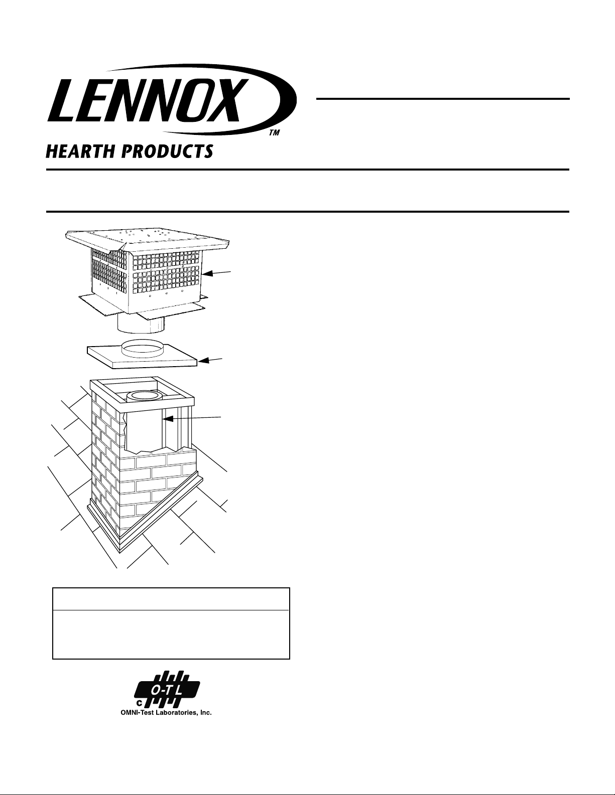
The SV4.5CTS and SV8CTS series terminations are designed to be
SV4.5CTS
Or SV8CTS
Termination
Chase Flashing
(Field Fabricated)
Pipe
Section
installed on top of locally fabricated chimney enclosure, referred to
herein as a chase. The terminations are designed to be used with tested
and listed Direct Vent pipe systems and manufactured appliances listed
for use with this product. The SV4.5CTS and SV8CTS terminations are
additionally designed and painted to be suitable for use by itself without
surround, providing a beautiful top to a standard chase.
WARNINGS
This termination is intended to be installed in accordance with the
installation guidelines of the pipe system and appliance it is joined to.
Failure to install this product within those guidelines as well as these
installation instructions can result in damage of property, bodily injury,
or death. The installation must conform with local codes or, with the
national fuel gas code, or ANSI Z223.1.
It is highly recommended that this product be installed by a qualified
technician. It is highly recommended that the technician be NFI certified
for gas appliance installations.
KIT CONTENTS
1 - Termination
1 - Bag with fifteen (15) stainless steel screws
1 - Instruction Sheet
NOTE: DIAGRAMS & ILLUSTRATIONS NOT TO SCALE.
APPROVALS AND LISTINGS
The SV4.5CTS and SV8CTS series terminations are tested as a integral
component of the Direct Vent pipe system and may be used with any
manufactured fireplace listed for use with these components. These
terminations are listed for this application by Omni-Test Laboratories.
FOR YOUR SAFETY
When working on ladders, roofs, scaffolding, or any high surface, take
precautions to protect against accidents. Properly secure ladders, wear
safety harnesses and verify all operations are done to OSHA standards.
Also be aware of and avoid any and all electrical wires in or near your
working area.
When working with and around sheet metal, be aware of material edges.
Always wear gloves, safety glass and any other needed protective gear
when working with sheet metal.
Take appropriate precautions when operating power equipment.
1
Page 2
CHASE CONSTRUCTION
INSTALLATION STEPS
The chase is a hollow vertical enclosure framed as a part of the building
and covered with a suitable exterior veneer. Always consult local building
codes for approved chase construction techniques.
The chase flashing, fabricated locally, is used to anchor the termination
to the chase. The flashing should be constructed to overlap the chase to
seal out the elements.
CHASE DIMENSIONS
The chase must be large enough to accommodate the vent system and its
required clearances to combustibles. The base of the Direct Vent Chase
Top Vertical Termination is nineteen and five eights inches (19 5/8" ) for
the SV4.5CTS and twenty three inches (23") for the SV8CTS. The chase
and its chase flashing must exceed those dimensions by one (1) inch on
all sides. This means the minimum chase dimensions must be a
minimum of twenty one and five eights inches (21 5/8" ) for the SV4.5CTS
and twenty five (25") for the SV8CTS.
TO INSTALL THE TERMINATION
The installation of this termination also requires additional components.
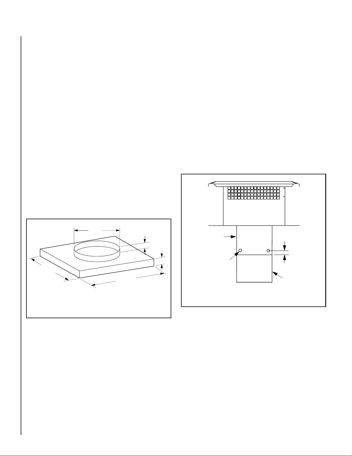
• Chase Flashing - The flashing should be a minimum 0.018" thick G90
galvanized steel or equivalent per ASTM 525. The chase flashing must
have, integrated into it, a vertical collar (
see Figure 1
).
Step 1. Install the gas appliance in accordance with its installation
instructions.
Step 2. Determine the chimney height vent configuration and number of
strait direct vent pipe sections required to bring the top of the last pipe
section flush with the chase top. Two inches (2") maximum above to
three inches (3") maximum below are the acceptable limits. Please see
the Installation Instructions accessories list for pipe information. Install
the direct vent pipe system.
If the top of the last pipe section exceeds the 3" maximum from the chase
top (up to 5" maximum), please use an adjustable length slip section
SV4.5LA (Cat. No. 77L75) or SV8LA (Cat. No. H2255) to engage the
termination with the pipe. See Step 3 for details.
Step 3. Install the sweaged side of the adjustable pipe section all the way
inside the termination. Secure it with three sheet metal screws (not
provided) one inch (1") above the termination outer collar bottom, in
three equally spaced places around the termination (
see Figure 2
).
(550 mm)
3/4" (38 mm) Min. to
2" (51 mm) Max.
2"
(51 mm)
**21-5/8" Min.
(550 mm)
*For SV8CTS - 12” (305 mm) I.D.
**For SV8CTS - 25” (635 mm)
*9"
(229 mm) I.D.
**21-5/8" Min.
Figure 1 Chase Flashing
Too short of a collar or no collar at all will allow water to seep into the
chase around the outside of the pipe system, and too tall of a collar will
interfere with the proper attachment of the termination.
The collared opening must be large enough to allow for the direct vent pipe
system to be installed and the termination outer collar to move freely. The
collared opening can be no larger than nine (9) inched in diameter.
• Strap Support - The SV4.5SU strap support is to be used for keeping
the vent pipe system in the center of the chase (
• Silicone Caulk - This is to be used for the final sealing of the
installation. The collar must be properly sealed to the chase flashing
with appropriate caulk. Hi-Temp sealant P/N 10K81 is recommended.
Failure to properly seal the collared opening will result in leakage into
the chase.
refer to Figure 3
).
Outer Collar
Sheet Metal Screw
# 8-32
(Three Places)
1"
Adjustable
Slip Section
(Sweaged
Side At Top)
Figure 2
Step 4. Install the SV4.5 pipe strap support (Cat. No. 96K93) or SV8SU
pipe strap support (Cat. No. H2262) to keep the vent system from
moving (
of one foot (1') to a maximum of 2 feet (2') below the chase top.
Step 5. Install the chase flashing on the top of the chase. Secure the
flashing to the top of the chase, using 8d nails.
Step 6. Connect the termination with the top pipe section. Slide the
termination inside pipe and lower it onto the chase flashing.
Step 7. Rotate the termination as needed to square it to the chase
flashing for proper aesthetic appearance.
see Figure 3
). The strap support should be placed a minimum
2
NOTE: DIAGRAMS & ILLUSTRATIONS NOT TO SCALE.
Page 3

Step 8. Once the termination is positioned, secure it to the chase
flashing using the stainless steel screws provided, through the prepunched attachment holes in the attachment tabs of the termination.
Be careful not to over tighten the screws so as to strip out the chase
flashing. In the event of a strip, a larger screw can be used so long
as it is stainless steel. DO NOT use common sheet metal screws, as
they will corrode over time and the termination will no longer be
secure at that point.
Step 9. Once the termination is permanently attached, seal all of the
screw tops with silicone. In order to properly apply the silicone, the
surface of the termination and screws must be clean and dry. Not sealing
the screws tops will result in water leakage into the chase.
VERTICAL VENT TERMINATION CLEARANCES
These instructions should be used as a guideline and do not supersede local codes in any way. Install SV4.5 vent according to the current
National Fuel Gas Code, ANSI-Z223.1 - latest edition, in the USA or CAN/
CGA-B149.1 and B149.2 - latest editions in Canada.
Terminate single vent caps relative to building components according to
Figure 4
.
Horizontal Overhang
Chase
Flashing
Chase
Pipe
Section
Strap
Support
2"
(Min.)
2 feet
(Max.)
1 foot
(Min.)
2"
(Max.)
3"
(Max.)
Figure 3
MAINTENANCE
As part of an annual inspection, the termination should be checked for
any foreign debris, animal or insect nests, or material of any kind which
may have become lodged in it. The exterior of the termination should be
visually inspected for damage of any kind.
In the event of damage to the termination, it should be replaced with a
new termination. All screw attachments should be checked to insure
they have not loosened over time and they should also be checked for
the water tightness of their silicon seal. The termination must be
removed to clean the chimney. Following cleaning, reinstall the termination and inspect as detailed in this document.
Vertical
Wall
2 FT MIN.
2 FT
MIN.
Lowest
Vent
Termination
Discharge
Opening
H*
X
12
Roof Pitch is X/12
*H = MINIMUM HEIGHT FROM ROOF TO
LOWEST DISCHARGE OPENING OF VENT
The vent/air intake termination clearances above the high side of
an angled roof is as shown in the following chart:
Termination Heights For Vents Above Flat Or
Slopped Roofs Ref. NFPA 54 / ANSI Z223.1, 7.6
hctiPfooR
H
)teef(
H
)sretem(
21/6ottalF0.13.0
21/7ot21/6revO52.183.0
21/8ot21/7revO5.164.0
21/9ot21/8revO0.216.0
21/01ot21/9revO5.267.0
21/11ot21/01revO52.399.0
21/21ot21/11revO0.422.1
21/41ot21/21revO0.525.1
21/61ot21/41revO0.638.1
21/81ot21/61revO0.731.2
21/02ot21/81revO5.792.2
21/12ot21/02revO0.844.2
Figure 4
NOTE: DIAGRAMS & ILLUSTRATIONS NOT TO SCALE.
3
Page 4

The manufacturer reserves the right to make changes at any time, without notice, in design,
materials, specifications, prices and also to discontinue colors, styles and products.
Consult your local distributor for fireplace code information.
Printed in U.S.A. © 2006 by Lennox Hearth Products
P/N 750,207M REV. A 07/2007
4
NOTE: DIAGRAMS & ILLUSTRATIONS NOT TO SCALE.
1110 West Taft Avenue • Orange, CA 92865
 Loading...