

Page 1
CARE AND OPERATION INSTRUCTIONS
▪
F
▪
R
▪
E
▪
E
▪
▪
See Page 2 For Details
▪
SAFETY
GUARD
PROTECTS AGAINST BURNS
AVERTISSEMENT : Assurez-vous de bien suivre les
instructions données dans cette notice pour réduire au
minimum le risque d’incindie ou d’explosion ou pour
éviter tout dommage matériel, toute blessure ou la mort.
WARNING: If the information in these instructions
is not followed exactly, a fire or explosion may
result, causing property damage, personal injury,
or death.
WARNING /AVERTISSEMENT/AVISO
• HOT GLASS WILL CAUSE
BURNS.
• DO NOT TOUCH GLASS
UNTIL COOLED.
• NEVER ALLOW CHILDREN
TO TOUCH GLASS.
• UNE SURFACE VITRÉE CHAUDE
PEUT CAUSER DES BRÛLURES.
• LAISSER REFROIDIR LA SURFACE
VITRÉE AVANT D'Y TOUCHER.
• NE PERMETTEZ JAMAIS À UN ENFANT
DE TOUCHER LA SURFACE VITRÉE.
• EL VIDRIO CALIENTE
CAUSARÁ QUEMADURAS.
• USTED DEBE NUNCA
TOCAR EL VIDRIO CALIENTE.
• LOS NIÑOS DEBEN NUNCA
TOCAR EL VIDRIO.
- Do not store or use gasoline or other flammable
vapors and liquids in the vicinity of this or any other
appliance.
- WHAT TO DO IF YOU SMELL GAS:
• Do not try to light any appliance.
• Do not touch any electrical switch; do not use any
phone in your building.
• Immediately call your gas supplier from a
neighbor’s phone. Follow the gas supplier’s
instructions.
• If you cannot reach your gas supplier, call the fire
department.
- Installation and service must be performed by a
qualified installer, service agency or the gas supplier.
- Ne pas entreposer ni utilizer d’essence ni d’autres vapeurs
ou liquides inflammables dans le voisinage de cet appareil
ou de tout autre appareil.
- QUE FAIRE SI VOUS SENTEZ UNE ODEUR DE GAZ :
• Ne pas tenter d’allumer d’appareil.
• Ne touchez à aucan interrupteur. Ne pas vous servir des
téléphones se trouvant dans le bâtiment où vous trouvez.
• Appelez immédiatement votre fournisseur de gaz depuis
un voisin. Suivez les instructions du fournisseur.
• Si vous ne pouvez rejoindre le fournisseur de gaz,
appelez le service des incindies.
- L’installation et l’entretien doivent être assurés par un
installateur ou un service d’entretien qualifié ou par le
fournisseur de gaz.
MPD Direct-Vent
Gas Fireplaces
P/N 875014M Rev. P 08/2011
This manual is one of a set of two supporting this product.
Refer to P/N 850014M for Installation Instructions.
Ce manuel est disponible en francais, simplement
en faire la demande. Numéro de la pièce 875014CF.
Table of Contents . . . . . . . . . . . . . . . . . . . . . . . . . . . . . . . . . . . . . . . . . . . 2
Safety and Your Fireplace. . . . . . . . . . . . . . . . . . . . . . . . . . . . . . . . . . . . 2
FREE Safety Guard Offer (Protects Against Burns) . . . . . . . . . . . . . . . . . 2
Important Safety Information . . . . . . . . . . . . . . . . . . . . . . . . . . . . . . . . . 4
Attaching the Safety-in-Operation Warnings . . . . . . . . . . . . . . . . . . . . . 5
[EN FRANÇAIS] L’information de sûreté importante . . . . . . . . . . . . . . . 3–4
Apposition des mises en garde relatives à la sécurité d’utilisation . . . . 5
[EN ESPAÑOL] Información importante de seguridad . . . . . . . . . . . . . . 3–4
Colocación de advertencias de seguridad en operación . . . . . . . . . . . . 5
Wait...
DON’T
THROW
IT AWAY!
This manual contains
important operating
and safety
information.
INSTALLER: Leave this manual with the appliance.
CONSUMER: Retain this manual for future reference.
INSTALLATEUR : Laissez cette notice avec l'appareil.
CONSOMMATEUR : Conservez cette notice pour consultation ultérieure.
MODELS
MPDT-3328CNM-B
MPDT-3328CPM-B
MPDR-3328CNM-B
MPDR-3328CPM-B
MPD-3530CNM-B
MPD-3530CPM-B
OTL Report No. 116-F-13-4
MILLIVOLT: ELECTRONIC:
MPD-4035CNM-B
MPD-4035CPM-B
MPD-4540CNM-B
MPD-4540CPM-B
Portland
US
MPDT-3328CNE-B
MPDT-3328CPE-B
MPDR-3328CNE-B
MPDR-3328CPE-B
MPD-3530CNE-B
MPD-3530CPE-B
MPD-4035CNE-B
MPD-4035CPE-B
MPD-4540CNE-B
MPD-4540CPE-B
Page 2
LENNOX HEARTH PRODUCTS • MERIT® PLUS DIRECT VENT GAS FIREPLACES (MPD33/35/40/45) • CARE AND OPERATION INSTRUCTIONS
Thank you for your purchase. We appreciate your business!
Please carefully read and follow all instructions in this manual.
Pay special attention to all warnings and safety information.
Following these safety, care, and operation instructions will help ensure
many years of dependable and enjoyable service from your fireplace.
Safety and
Your Fireplace
Register your product online today!
To help us keep you up-to-date on product information and offers,
please take a few moments to register your product online at
www.lennox.com (Hearth / Owner Resources)
•
FREE
The Lennox® SAFETY GUARD protects against
severe burns and injuries by preventing direct contact
To receive your FREE SAFETY GUARD, call 1-800-786-7976
SAFETY GUARD
with the front glass surface of your fireplace.
or visit
www.lennox.com (Hearth / Owner Resources).
Note: Safety Guards may not be available for some
older models that are no longer in production.
.
OFFER
•
Table of Contents
Safety and Your Fireplace. . . . . . . . . . . . . . . . . . . . . . . . . . . . . . . . . . . . . . . . 2
Important Safety Information . . . . . . . . . . . . . . . . . . . . . . . . . . . . . . . . . . . . . 4
Attaching the Safety-in-Operation Warnings . . . . . . . . . . . . . . . . . . . . . . . . . 5
Appliance Installation, Service, and Maintenance Notices . . . . . . . . . . . . . . . . . 6
Appliance Operation Notices . . . . . . . . . . . . . . . . . . . . . . . . . . . . . . . . . . . . . . . 6
Warranty Information . . . . . . . . . . . . . . . . . . . . . . . . . . . . . . . . . . . . . . . . . . . . . 6
General Information . . . . . . . . . . . . . . . . . . . . . . . . . . . . . . . . . . . . . . . . . . . . . 6
BTU Input . . . . . . . . . . . . . . . . . . . . . . . . . . . . . . . . . . . . . . . . . . . . . . . . . . . . 7
Gas Pressure Requirements . . . . . . . . . . . . . . . . . . . . . . . . . . . . . . . . . . . . . . 7
Orifice Sizes . . . . . . . . . . . . . . . . . . . . . . . . . . . . . . . . . . . . . . . . . . . . . . . . . . 7
Burn-In Period . . . . . . . . . . . . . . . . . . . . . . . . . . . . . . . . . . . . . . . . . . . . . . . . 7
Operation/Care of Your Appliance . . . . . . . . . . . . . . . . . . . . . . . . . . . . . . . . . . . 8
Gas Controls Access . . . . . . . . . . . . . . . . . . . . . . . . . . . . . . . . . . . . . . . . . . . . . 8
Variable Flame Adjustment . . . . . . . . . . . . . . . . . . . . . . . . . . . . . . . . . . . . . . . . . 9
Maintenance . . . . . . . . . . . . . . . . . . . . . . . . . . . . . . . . . . . . . . . . . . . . . . . . . . . 10
Front Glass Enclosure Panel, Removal and Installation . . . . . . . . . . . . . . . . . . 11
Install Volcanic Stone, Embers and Logs . . . . . . . . . . . . . . . . . . . . . . . . . . . . . 12
Burner Flame Appearance/Sooting . . . . . . . . . . . . . . . . . . . . . . . . . . . . . . . . . . 16
Burner Flame Adjustments . . . . . . . . . . . . . . . . . . . . . . . . . . . . . . . . . . . . . . . . 17
Millivolt Appliance Checkout . . . . . . . . . . . . . . . . . . . . . . . . . . . . . . . . . . . . . . 17
Electronic Appliance Checkout . . . . . . . . . . . . . . . . . . . . . . . . . . . . . . . . . . . . . 17
Wiring Diagrams . . . . . . . . . . . . . . . . . . . . . . . . . . . . . . . . . . . . . . . . . . . . . . . 18
Warranty . . . . . . . . . . . . . . . . . . . . . . . . . . . . . . . . . . . . . . . . . . . . . . . . . . . . . 18
Ordering Replacement Parts . . . . . . . . . . . . . . . . . . . . . . . . . . . . . . . . . . . . . . 18
Product Reference Information . . . . . . . . . . . . . . . . . . . . . . . . . . . . . . . . . . . . 18
Fireplace Shipping Weights/Volumes . . . . . . . . . . . . . . . . . . . . . . . . . . . . . . . . 19
Accessory Components . . . . . . . . . . . . . . . . . . . . . . . . . . . . . . . . . . . . . . . . . . 19
Maintenance Schedule . . . . . . . . . . . . . . . . . . . . . . . . . . . . . . . . . . . . . . . . . . . 25
Lighting Instructions – Millivolt . . . . . . . . . . . . . . . . . . . . . . . . . . . . . . . . . . . . 26
Lighting Instructions – Electronic . . . . . . . . . . . . . . . . . . . . . . . . . . . . . . . . . . 28
Troubleshooting Guide – Millivolt Gas Control System . . . . . . . . . . . . . . . . . . 30
Troubleshooting Guide – Electronic Gas Control System . . . . . . . . . . . . . . . . . 31
Replacement Parts List . . . . . . . . . . . . . . . . . . . . . . . . . . . . . . . . . . . . . . . . . . 32
All parts of your Lennox
Hearth Products fireplace
get EXTREMELY HOT!
To prevent severe burns and injuries, install
a screen or physical barrier to prevent direct
contact with the glass.
To order a FREE Lennox® SAFETY GUARD
for your fireplace, see details at left.
Follow the safety instructions below
and be sure everyone in your household
understands this burn hazard:
• The surfaces on your fireplace get
EXTREMELY HOT!
• The glass on the front
of the fireplace reaches
EXTREMELY HIGH
temperatures and can
cause severe burns if touched.
• Keep children away from an operating
fireplace. Closely supervise children in
any room where a fireplace is operating
to prevent contact with glass.
• Keep clothing, furniture,
gasoline, and other
flammable liquids away
from the fireplace.
• Even after the gas is turned off, fireplace
surfaces remain extremely hot.
Be sure to attach the enclosed Safety-in-
Operation Warnings where you turn on your
fireplace, to help remind everyone of the
dangers associated with high temperatures
(see page 5).
Read Important Safety Information on
page 4.
2
Page 3
LENNOX HEARTH PRODUCTS • MERIT® PLUS DIRECT VENT GAS FIREPLACES (MPD33/35/40/45) • CARE AND OPERATION INSTRUCTIONS
[FRENCH] [SPANISH]
La sécurité et
votre foyer
Toutes les parties de votre foyer
Lennox Hearth Products deviennent
EXTRÊMEMENT CHAUDES !
Afin d'éviter de vous brûler gravement ou de
vous blesser, installez une grille ou une barrière
physique pour empêcher tout contact direct
avec la vitre.
Pour commander un PANNEAU DE PROTECTION
Lennox® GRATUIT pour votre foyer, consultez
les détails dans la partie gauche.
Suivez les instructions de sécurité ci-dessous
et veillez à ce que tous les membres de votre
famille soient conscients du danger de brûlure
encouru :
• Les surfaces de votre foyer deviennent
EXTRÊMEMENT CHAUDES !
• La vitre située à l'avant du foyer
atteint des températures
EXTRÊMEMENT ÉLEVÉES et peut causer
de graves blessures en cas de contact.
• Tenez les enfants à l'écart du foyer lorsqu'il
fonctionne. Surveillez attentivement
les enfants dans les pièces où un foyer
est utilisé afin d'éviter qu'ils ne soient
en contact avec la vitre.
• Tenez tous les vêtements, les
meubles, l'essence et tout autre
liquide inflammable à l'écart du foyer.
• Même après fermeture du gaz, les surfaces
du foyer restent extrêmement chaudes.
Seguridad y
su chimenea
¡Todas las partes de la chimenea
Lennox Hearth Products se ponen
MUY CALIENTES!
Instale una malla o barrera física para evitar
el contacto directo con el vidrio y prevenir
las quemaduras y lesiones graves.
Ver los detalles a la izquierda para ordenar
un Lennox® SAFETY GUARD GRATIS
para su chimenea.
Siga las instrucciones de seguridad a
continuación y asegúrese de que todos
en su hogar sepan acerca de este peligro
de quemadura:
• ¡Las superficies de la chimenea se ponen
MUY CALIENTES!
• El vidrio delante de la chimenea alcanza
temperaturas EXTREMADAMENTE ALTAS y
puede causar quemaduras graves si se toca.
• Mantenga a los niños alejados de la
chimenea en funcionamiento. Supervise
en forma cercana a los niños en cualquier
cuarto donde haya una chimenea
funcionando para impedir el contacto
con el vidrio.
• Mantenga la ropa, mobiliario, gasolina
y otros líquidos inflamables alejados
de la chimenea.
• Aún después de haber apagado el gas,
las superficies de la chimenea permanecen
extremadamente calientes.
Veillez à coller les Étiquettes de mise en garde
relatives à la sécurité d'utilisation à l'endroit
où vous utilisez le foyer, pour rappeler à tous les
utilisateurs les dangers liés aux températures
élevées (voir page 5).
Lisez la section Informations importantes
relatives à la sécurité, page 4.
Asegúrese de colocar las Etiquetas de
advertencia de seguridad de operación en
el lugar donde enciende la chimenea, para
que todos recuerden los peligros asociados
con las altas temperaturas (ver la página 5).
Lea la Información importante de seguridad
en la página 4.
3
Page 4

LENNOX HEARTH PRODUCTS • MERIT® PLUS DIRECT VENT GAS FIREPLACES (MPD33/35/40/45) • CARE AND OPERATION INSTRUCTIONS
Important Safety Information
1. WARNING: Do not operate appliance with the glass front
removed, cracked or broken. Replacement of the glass
should be done by a licensed or qualified service person .
2. Do not use this appliance if any part has been under water.
Immediately call a qualified service technician to inspect
the appliance and to replace any part of the control system
and any gas control which has been under water.
3. Due to high temperatures, the appliance should be located
out of traffic and away from furniture and draperies.
4. Children and adults should be alerted to the hazards of
high surface temperature and should stay away to avoid
burns or clothing ignition.
5. Clothing or other flammable material should not be placed
on or near the appliance.
6. Young children should be carefully supervised when they
are in the same room as the appliance. Toddlers, young
children, and others may be susceptible to accidental
contact burns. A physical barrier is recommended if there
are at-risk individuals in the house. To restrict access to a
fireplace or stove, install an adjustable safety gate to keep
toddlers, young children, and other at-risk individuals out
of the room and away from hot surfaces.
7. Any safety screen or guard removed for servicing an
appliance must be replaced prior to operating the
appliance.
8. Installation and repair should be done by a qualified
service person. The appliance should be inspected
before use and at least annually by a professional service
person. More frequent cleaning may be required due to
excessive lint from carpeting, bedding material, et cetera.
It is imperative that control compartments, burners, and
circulating air passageways of the appliance be kept
clean. See maintenance instructions on page 10.
L’information de sûreté importante
1. AVERTISSEMENT. Ne pas utiliser l’appareil si le panneau frontal
en verre n’est pas en place, est craqué ou brisé. Confiez le
remplacement du panneau à un technicien agréé
2. Ne pas utiliser cet appareil s’il a été plongé, même partiellement,
dans l’eau. Appeler un technicien qualifié pour inspecter
l’appareil et remplacer toute partie du système de commande
et toute commande qui a été plongée dans l’eau.
3. En raison des températures élevées, l’appareil devrait être
installé dans un endroit où il y a peu de circulation et loin du
mobilier et des tentures.
4. Les enfants et les adultes devraient être informés des dangers
que posent les températures de surface élevées et se tenir à
distance afin d’éviter des brûlures ou que leurs vêtements ne
s’enflamment.
5. On ne devrait pas placer de vêtements ni d’autres matières
inflammables sur l’appareil ni à proximité.
6. Les jeunes enfants devraient être surveillés étroitement lorsqu’ils
se trouvent dans la même pièce que l’appareil. Les tout petits,
les jeunes enfants ou les adultes peuvent subir des brûlures s’ils
viennent en contact avec la surface chaude. Il est recommandé
d’installer une barrière physique si des personnes à risques
habitent la maison. Pour empêcher l’accès à un foyer ou à un
poêle, installez une barrière de sécurité ; cette mesure empêchera
les tout petits, les jeunes enfants et toute autre personne à risque
d’avoir accès à la pièce et aux surfaces chaudes.
7. Tout écran ou protecteur retiré pour permettre l’entretien de
l’appareil doit être remis en place avant de mettre l’appareil en
marche.
8. L’installation et la réparation devrait être confiées à un technicien
qualifié. L’appareil devrait faire l’objet d’une inspection par un
technicien professionnel avant d’être utilisé et au moins une
fois l’an par la suite. Des nettoyages plus fréquents peuvent
être nécessaires si les tapis, la literie, et cetera produisent
une quantité importante de poussière. Il est essentiel que les
compartiments abritant les commandes, les brûleurs et les
conduits de circulation d’air de l’appareil soient tenus propres.
Voyez les instructions d’entretien à la page 10.
[SPANISH]
Información importante de seguridad
1. ADVERTENCIA: No opere el artefacto con el frente de vidrio quitado,
agrietado o roto. Un técnico de servicio licenciado o capacitado
debe reemplazar el vidrio.
2. No use este artefacto si alguna de sus partes ha estado bajo agua.
Llame de inmediato a un técnico de servicio calificado para que
inspeccione el artefacto y reemplace cualquier parte del sistema
de control y cualquier control de gas que haya estado bajo agua.
3. Debido a las altas temperaturas, el artefacto debe situarse fuera
de las áreas de tráfico y lejos del mobiliario y cortinas.
4. Se debe alertar a los niños y adultos sobre los peligros de
las altas temperaturas en la superficie y que se mantengan
alejados para evitar quemaduras o ignición de la ropa.
5. No debe colocarse ropa u otros materiales inflamables
4
sobre y cerca del artefacto.
6. Se debe supervisar de cerca a los niños cuando estén en el mismo
cuarto que el artefacto. Los niños pequeños, los jóvenes y otras
personas pueden ser susceptibles a quemaduras por contacto
accidental. Se recomienda instalar una barrera física si hay
personas en riesgo en la casa. Para restringir el acceso a una
chimenea o estufa, instale una puerta de seguridad ajustable
para mantener a los niños pequeños, jóvenes y otras personas
en riesgo fuera del cuarto y lejos de las superficies calientes.
7. Cualquier malla o resguardo de seguridad quitado para dar servicio
a un artefacto, debe reinstalarse antes de operar el artefacto.
8. Una persona de servicio competente debe realizar la instalación y
reparación. Una persona de servicio profesional debe inspeccionar
el artefacto antes de usar al menos una vez por año. Se puede
requerir limpieza más frecuente debido a la pelusa excesiva
del alfombrado, del material de cobijas, etc. Es imprescindible
mantener limpios los compartimientos de control, los quemadores
y los pasajes de circulación del aire del artefacto. Ver las
instrucciones de mantenimiento en la página 10.
Page 5
LENNOX HEARTH PRODUCTS • MERIT® PLUS DIRECT VENT GAS FIREPLACES (MPD33/35/40/45) • CARE AND OPERATION INSTRUCTIONS
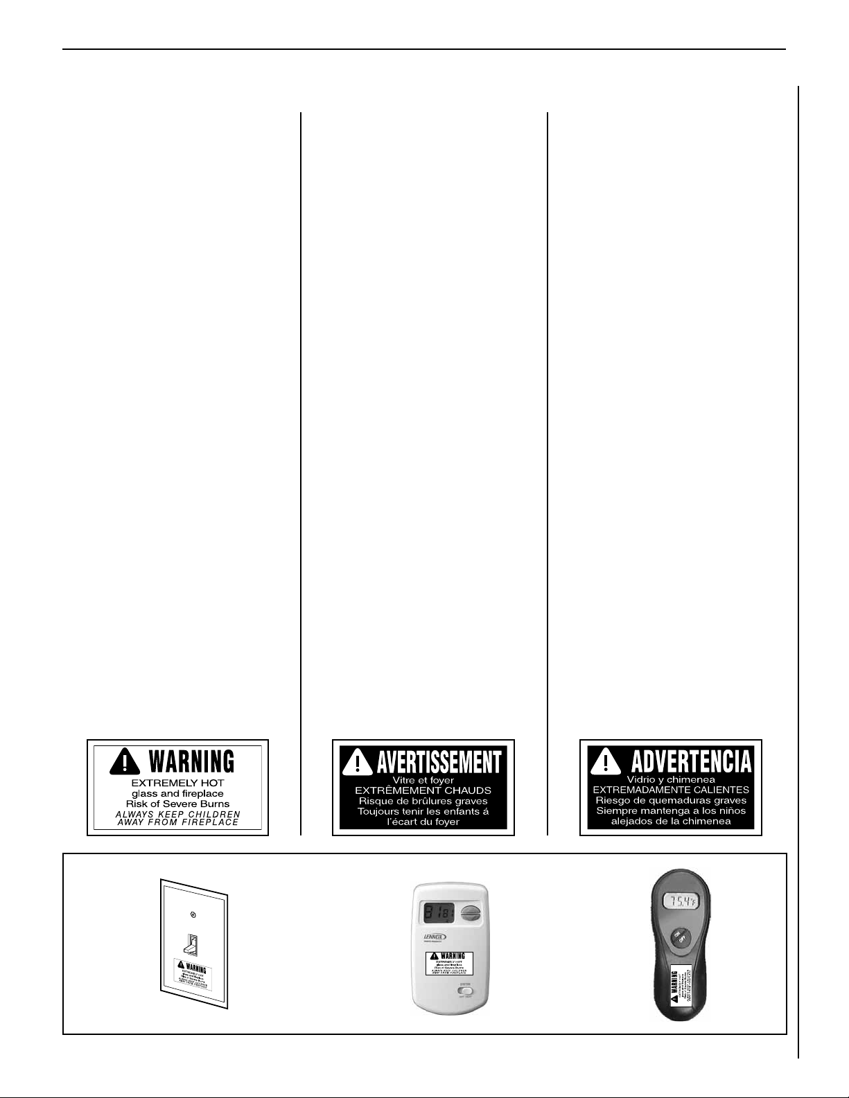
HOMEOWNER’S INSTRUCTIONS - ATTACHING SAFETY-IN-OPERATION WARNINGS
ATTACHING SAFETY-IN-OPERATION
WARNINGS
Your fireplace has been furnished with safety instruction labels that are to be affixed to the operation and
control point of the fireplace. A safety instruction
label should be affixed to the wall switch plate where
the fireplace is turned on and off (See Figure A) or
wall thermostat (See Figure B) and if used on the
remote control handheld transmitter (Figure C).
The warnings should already have been put in place
when the fireplace initial set-up was completed.
If they are not affixed at these spots, locate the
multi-lingual adhesive labels provided with these
instructions and proceed as follows:
1. Locate the wall switch or wall thermostat that
controls the fireplace (verify the switch operates
the fireplace by turning it on and off). Clean the
wall switch plate or wall thermostat thoroughly
to remove any dust and oils. Affix the label to
the surface of the plate of the wall switch that
controls the fireplace (Figure A) or the wall
thermostat (Figure B). Choose the language
primarily spoken in the home.
2. If a remote control is used to control the fireplace,
locate the transmitter and clean it thoroughly
to remove any dust and oils. Affix the label to
the surface of handheld transmitter (Figure C).
Choose the language primarily spoken in the
home.
3. If you are unable to locate the labels, please call
Lennox Hearth Products or your nearest Lennox
Hearth Products dealer to receive additional
safety instruction labels free of charge.
Cat. No. H8024 Replacement Label Kit
LENNOX HEARTH PRODUCTS
1-800-9-LENNOX
Note: English is red text on clear label. French and
Spanish are white text on black label.
APPOSITION DES MISES EN GARDE RELATIVES
À LA SÉCURITÉ D’UTILISATION
Votre foyer a été livré avec des étiquettes de sécurité qui
doivent être collées à côté des dispositifs de contrôle
du foyer. Une étiquette de sécurité doit être collée sur
la plaque de l’interrupteur contrôlant l’allumage du
foyer (voir Figure A) ou sur le thermostat mural (voir
Figure B) et, le cas échéant, sur le boîtier de la télé-
commande (Figure C). Les mises en garde auraient dû
être collées au moment de l’installation initiale du foyer.
Si ce n’est pas le cas, prenez les étiquettes adhésives
multilingues fournies avec ces instructions et procédez
comme suit:
1. Repérez l’interrupteur ou le thermostat mural
qui contrôle le foyer (vérifiez que l’interrupteur
contrôle le fonctionnement du foyer en le faisant
basculer de Marche à Arrêt, et vice-versa). Nettoyez
soigneusement la plaque murale de l’interrupteur
ou le thermostat mural pour éliminer la poussière
et les traces de graisse ou d’huile. Collez l’étiquette
sur la surface de la plaque de l’interrupteur mural
qui contrôle le foyer (Figure A) ou du thermostat
mural (Figure B). Choisissez la langue qui est
principalement parlée dans la résidence du
propriétaire.
2. Si une télécommande est utilisée pour contrôler
le foyer, nettoyez la soigneusement pour éliminer
la poussière et les traces de graisse ou d’huile.
Collez l’étiquette sur le boîtier de la télécommande
(Figure C). Choisissez la langue qui est principale-
ment parlée dans la résidence du propriétaire.
3. Si vous ne trouvez pas les étiquettes, veuillez
appeler Lennox Hearth Products ou votre distributeur Lennox Hearth Products local pour recevoir
gratuitement des étiquettes supplémentaires.
Étiquettes de remplacement, n° cat. H8024
LENNOX HEARTH PRODUCTS
1-800-9-LENNOX
Remarque : Le texte anglais est rouge sur un support
transparent. Le texte français et espagnol est blanc
sur un support noir.
COLOCACIÓN DE ADVERTENCIAS DE
SEGURIDAD EN OPERACIÓN
Su chimenea incluye etiquetas de instrucciones de
seguridad que deben colocarse en el punto de operación
y control de la chimenea. Se debe colocar una etiqueta de
instrucciones de seguridad en la placa del interruptor de
pared desde el cual se enciende y se apaga la chimenea
(ver la Figura A) o en el termostato de pared (ver la Figura
B) y en el transmisor de control remoto (Figura C) si
se usa. Las advertencias ya deben haberse colocado
cuando se completó la instalación inicial de la chimenea.
Si no están colocadas en estos lugares, encuentre las
etiquetas adhesivas multilingües proporcionadas con
estas instrucciones y prosiga de la siguiente manera:
1. Identifique el interruptor o el termostato de pared
que controla la chimenea (verifique que el interruptor
opera la chimenea encendiéndola y apagándola).
Limpie bien la placa del interruptor o el termostato de
pared para quitar el polvo y aceite. Pegue la etiqueta
en la superficie de la placa del interruptor que controla
la chimenea (Figura A) o en el termostato de pared
(Figura B). Seleccione el idioma que más se habla
en la casa.
2. Si se usa un control remoto para controlar la
chimenea, encuentre el transmisor y límpielo bien
para quitar el polvo y aceite. Pegue la etiqueta en la
superficie del transmisor (Figura C). Seleccione el
idioma que más se habla en la casa.
3. Si no puede encontrar las etiquetas, sírvase llamar a
Lennox Hearth Products o al distribuidor de Lennox
Hearth Products más cercano para recibir etiquetas
de instrucciones de seguridad adicionales gratuitas.
Juego de etiquetas de repuesto - Nº de cat. H8024
LENNOX HEARTH PRODUCTS
1-800-9-LENNOX
Nota: La etiqueta en inglés es transparente con texto
rojo. Las etiquetas en francés y español son negras
con texto blanco.
Figure A
SAFETY LABEL
DIAGRAMS
DIAGRAMMES DES ÉTIQUETTES
DE SÉCURITÉ
Figure B
NOTE: DIAGRAMS & ILLUSTRATIONS ARE NOT TO SCALE.
DIAGRAMAS DE ETIQUETAS
DE SEGURIDAD
Figure C
5
Page 6

LENNOX HEARTH PRODUCTS • MERIT® PLUS DIRECT VENT GAS FIREPLACES (MPD33/35/40/45) • CARE AND OPERATION INSTRUCTIONS
APPLIANCE INSTALLATION, SERVICE,
AND MAINTENANCE NOTICES
IMPORTANT: Improper installation,
adjustment, alteration, service, or
maintenance can cause injury or property
damage. Refer to this manual. For
assistance or additional information,
consult a qualified installer, service
agency or the gas supplier.
Only trim kit(s) supplied by the manufacturer shall be used in the installation of
this appliance.
Draft relief openings must not be covered
or blocked.
These appliances must not be connected
to a chimney or flue serving a separate
solid fuel burning appliance.
Any change to this appliance and/or
its operating controls is dangerous.
Improper installation or use of this
appliance can cause serious injury or
death from fire, burns, explosion or
carbon monoxide poisoning.
CARBON MONOXIDE POISONING: Early
signs of carbon monoxide poisoning are
similar to the flu with headaches, dizziness and/or nausea. If you have these
signs, obtain fresh air immediately.
Turn off the gas supply to the appliance
and have it serviced by a qualified
professional, as it may not be operating
correctly. Some people are more
affected by carbon monoxide than others,
including pregnant women, people with
heart or lung disease or anemia, those
under the influence of alcohol, and those
at high altitudes.
Turn off gas and electrical power to the
fireplace and allow it to cool before
cleaning or servicing the appliance.
The vent termination is hot while in
operation and for a period of time following the use of the fireplace. Young
children should be carefully supervised
when they are in the same area as a hot
termination
6
APPLIANCE OPERATION NOTICES
Do not operate appliance with the glass
front removed, cracked, or broken.
These fireplaces are vented gas appliances. Do not burn wood or other
material in these appliances.
This appliance is only for use with the
type of gas indicated on rating plate. This
appliance is not convertible for use with
other gases, unless a certified kit is used.
These appliances are designed to operate
on natural gas or propane gas only. The
use of other fuels or combinations of
fuels will degrade the performance of this
system and may be dangerous.
Provide adequate clearances around
air openings and adequate accessibility
clearance for service and proper operation. Never obstruct the front openings
of the appliance.
Do not use this appliance if any part has
been under water. Immediately call a
qualified service technician to inspect
the appliance and to replace any part of
the control system and any gas control
that has been under water.
These fireplaces are designed as supplemental heaters. Therefore, it is advisable
to have an alternate primary heat source
when installed in a dwelling.
NOTE: DIAGRAMS & ILLUSTRATIONS ARE NOT TO SCALE.
WARRANTY INFORMATION
Your gas appliance is covered by a limited
twenty-year warranty. You will find a copy of
the warranty accompanying this manual. Please
read the warranty to be familiar with its coverage.
Retain this manual. File it with your other documents for future reference.
Failure to comply with the installation
and operating instructions provided
will result in an improperly installed
and operating appliance, voiding its
warranty.
Do not attempt to alter or modify the
construction of the appliance or its components. Any modification or alteration
may void the warranty, certification, and
listings of this unit.
GENERAL INFORMATION
The fireplace models covered in this manual
are direct-vent sealed combustion gas fireplace
heaters designed for residential application.
These direct-vent appliances operate with the
combustion chamber completely isolated from
the indoor environment.
All air for combustion is brought in from the
outside and exhaust gases are vented through
the same direct-vent, co-axial (intake/exhaust)
vent system.
The Millivolt appliances have a millivolt gas
control valve with piezo ignition system. If any
optional accessories which require electrical
power are being installed, the electrical power
must be provided at the time of appliance installation.
The Electronic appliances are designed to
operate on either natural or propane gas. An
electronic intermittent pilot system provides
safe, efficient operation. External electrical
power is required to operate these units.
These appliances comply with National
Safety Standards and are tested and listed
by OMNI-Test Laboratories, Inc. (Report No.
116-F-13-4) to ANSI ZZ21.88 (in Canada, CSA-
2.33), and CAN/CGA-2.17-M91 in both USA and
Canada, as vented gas fireplace heaters.
The Installation must conform to local codes
or, in the absence of local codes, with the
National Fuel Gas Code, ANSI Z223.1/NFPA
54-latest edition, or the Natural Gas and Propane
Installation Code, CAN/CSA B149.1-latest edition. The appliance, when installed, must be
electrically grounded in accordance with local
codes or, in the absence of local codes, the
latest edition of the National Electrical Code,
ANSI/NFPA 70, or the Canadian Electrical Code,
CSA C22.1 - latest editions.
Page 7
LENNOX HEARTH PRODUCTS • MERIT® PLUS DIRECT VENT GAS FIREPLACES (MPD33/35/40/45) • CARE AND OPERATION INSTRUCTIONS
GENERAL INFORMATION (continued)
BTU Input
These fireplaces are designed as supplemental
heaters. Therefore, it is advisable to have an
alternate primary heat source when installed
in a dwelling.
Millivolt Models - The millivolt appliances are
manually controlled and feature a spark igniter
(piezo) that allows the appliance's pilot gas to
be lit without the use of matches or batteries.
This system provides continued service in the
event of a power outage.
Millivolt models come standard with a manuallymodulated gas valve; flame appearance and heat
output can be controlled at the gas valve. The BTU
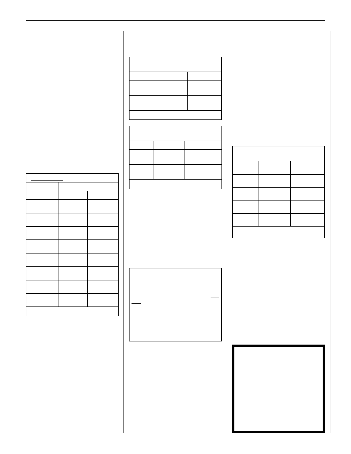
Input for these appliances is shown in Table 1.
Electronic Models - Electronic models have a
fixed rate gas valve. Input of electronic models
is shown in Table 1.
Input (BTU/HR) Gas Valves (all models)
Input Rate (BTU / HR)
Models
MPDT/R-3328
(Millivolt)
MPD-3530
(Millivolt)
MPD-4035
(Millivolt)
MPD-4540
(Millivolt)
MPDT/R-3328
(Electronic)
MPD3530
(Electronic)
MPD4035
(Electronic)
MPD4540
(Electronic)
Nat. Gas Prop. Gas
17,500 high
11,700 low
20,000 high
12,800 low
27,000 high
18,500 low
29,000 high
20,500 low
17,500 17,500
20,000 20,000
27,000 27,000
29,000 29,000
17,500 high
14,000 low
20,000 high
15,200 low
27,000 high
21,500 low
29,000 high
22,500 low
Table 1
Gas Pressure - All Models
Tables 2 and 3 show the appliances' inlet and
manifold gas pressure requirements:
Inlet Gas Supply Pressure
(all models)
Fuel # Minimum Maximum
Natural Gas
Propane
4.5" WC
(1.12 kPa)
11.0" WC
(2.74 kPa)
10.5" WC
(2.61 kPa)
13.0" WC
(3.23 kPa)
Table 2
Manifold Gas Supply Pressure
(all models)
Fuel # Low High
Natural
Gas
Propane
(Lo) 1.6" WC
(0.40 kPa)
(Lo) 6.3" WC
(1.57 kPa)
(Hi) 3.5" WC
(0.87 kPa)
(Hi) 10.0" WC
(2.49 kPa)
Table 3
Test gauge connections are provided on the
front of the millivolt and electronic gas control
valve (identified IN for the inlet and OUT for the
manifold side). The control valves have a 3/8"
(10mm) NPT thread inlet and outlet side of the
valve (refer to Figures 1 and 2).
Propane tanks are at pressures that will cause
damage to valve components. Verify that the
tanks have step down regulators to reduce the
pressure to safe levels.
These appliances must be isolated from the
gas supply piping system (by closing their
individual manual shut-off valve) during any
pressure testing of the gas supply piping
system at test pressures equal to or less
than 1/2 psig (3.5 kPa).
These appliances and their individual shut-off
valves must be disconnected from the gas
supply piping system during any pressure
testing of that system at pressures greater
than 1/2 psig (3.5 kPa).
Deration - At higher elevations, the amount
of BTU fuel value delivered must be reduced
by either using gas that has been derated by
the gas company or by changing the burner
orifice to a smaller size as regulated by the
local authorities having jurisdiction and by the
(USA) National Fuel Gas Code NFPA 54/ANSI
Z223.1 - latest edition or, in Canada, the CAN/
CSA-B149.1 codes - latest edition.
Install the appliance according to the regulations
of the local authorities having jurisdiction and,
in the USA, the National Fuel Gas Code NFPA
54 / ANSI Z223.1 - latest edition or, in Canada,
the CAN/CSA-B149.1 - latest edition.
Flame breadth, height and width will dimenish
4% for every 1,000 feet of altitude.
Burner Orifice Sizes
Elevation 0-4500 feet ( 0-1372 meters)
Model
Series
MPDT-3328
MPDR-3328
MPD-3530
MPD-4035
MPD-4540
Table 4
Nat.Gas
drill size (inches)
#45 (0.0820")*
39L66•
#44 (0.0860")*
60J80•
#37 (0.1040")*
24M10•
#36 (0.1065")*
18L40•
* Standard size installed at factory
• Part /Cat. Number
Propane
drill size (inches)
0.048 inch
99K78•
#55 (0.0520")*
19L52•
0.063 inch
21L01•
#52 (0.0635")*
37G00•
Burn-in Period
During the first few fires of this appliance there
will be some odor due to the curing of the
paint and burning off of lubricants used in the
manufacturing process. Depending on your
use, the burn-in period may take a few hours
or a few days.
KEEP YOUR HOUSE WELL VENTILATED
DURING THE CURING PROCESS. THE ODOR
AND HAZE EMITTED DURING THE CURING
PROCESS CAN BE QUITE NOTICEABLE AND
MAY SET OFF A SMOKE DETECTOR.
If an optional blower is installed, do not turn it
on during the burn-in period.
These appliances must not be connected to a
chimney or flue serving a separate solid fuel
burning appliance.
Orifice Sizes - Sea Level to High Altitude
(All Models)
These appliances are tested and approved for
installation at elevations of 0-4500 feet (0-1372
meters) above sea level using the standard burner
orifice sizes (marked with an "*" in Table 4 ).
For elevations above 4500 feet, contact your
gas supplier or qualified service technician.
NOTE: DIAGRAMS & ILLUSTRATIONS ARE NOT TO SCALE.
NOTICE: A white film may develop
on the glass enclosure panel during
the first few fires as part of the burn-in
process.
The first few times you use the
fireplace, clean the glass after each use
(AFTER THE GLASS HAS COMPLETELY
COOLED); otherwise, the white film
will bake onto the glass and become
difficult to remove.
See glass cleaning instructions on
Page 9.
7
Page 8
LENNOX HEARTH PRODUCTS • MERIT® PLUS DIRECT VENT GAS FIREPLACES (MPD33/35/40/45) • CARE AND OPERATION INSTRUCTIONS
OPERATION AND CARE OF YOUR APPLIANCE
WARNING
Young children should be carefully supervised when they are in the
same room as the appliance. Toddlers, young children and others
may be susceptible to accidental contact burns. A physical barrier is
recommended if there are at risk individuals in the house. To restrict
access to a fireplace or stove, install an adjustable safety gate to keep
toddlers, young children and other at risk individuals out of the room
and away from hot surfaces.
AVERTISSEMENT
SIT Gas Valve
Piezo
Ignitor
Les jeunes enfants devraient être surveillés étroitement lorsqu’ils se trouvent dans la même pièce que l’appareil. Les tout petits, les jeunes enfants
ou les adultes peuvent subir des brûlures s’ils viennent en contact avec
la surface chaude. Il est recommandé d’installer une barrière physique
si des personnes à risques habitent la maison. Pour empêcher l’accès
à un foyer ou à un poêle, installez une barrière de sécurité; cette mesure
empêchera les tout petits, les jeunes enfants et toute autre personne à
risque d’avoir accès à la pièce et aux surfaces chaudes.
Gas Controls/Control Compartment
Access
Operation of millivolt and electronic gas control systems is different. Before lighting and
operating your appliance, determine whether
you have a millivolt or electronic appliance.
The gas controls can be found behind the lower
access panel.
To open the panel, press the upper right corner
of the panel until the spring-loaded magnetic
catch is released. Then gently pull the panel
forward to release the left magnetic catch and
allow the panel to swing down to open.
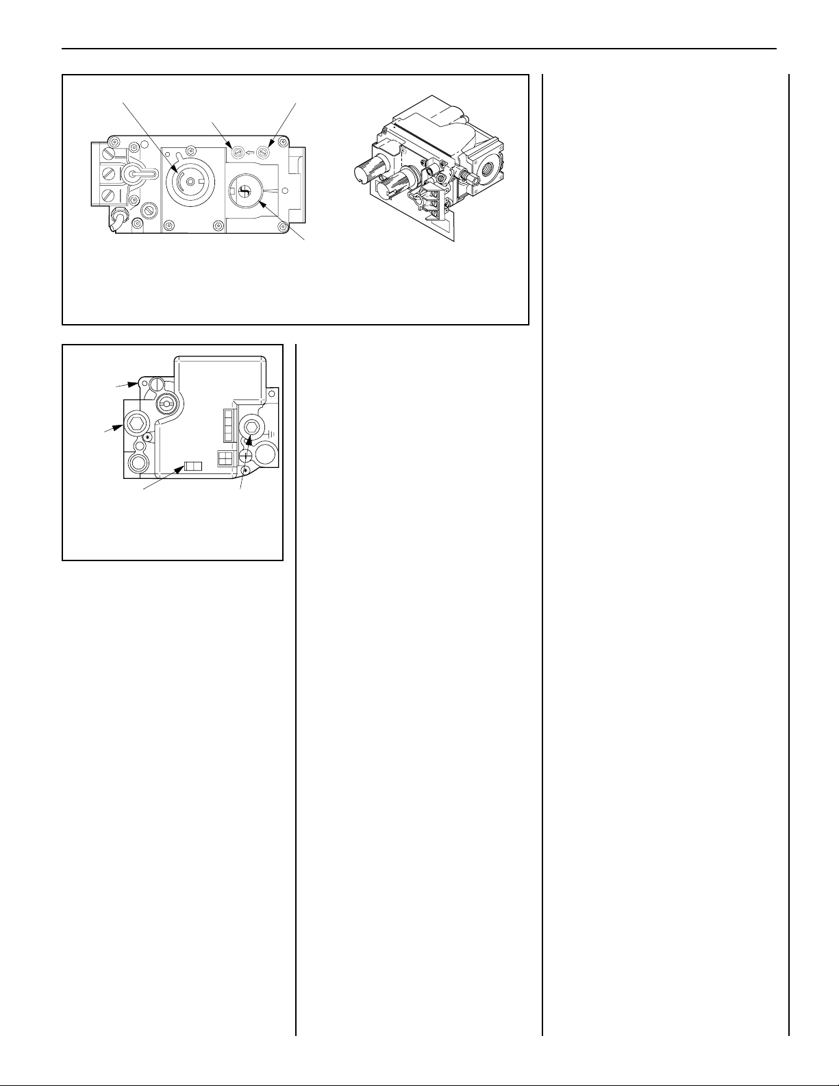
On millivolt systems, the piezo ignitor, Hi/Lo
flame adjustment knob, pilot and main gas ON/
OFF control knob, and gas valve (Figure 1) are
located behind the lower access panel.
To remove the lower access panel, slide the
hinge pin on the left side of the panel to the
RIGHT until it disengages from the left corner
post hole. Pull the panel diagonally to the LEFT,
away from the fireplace.
To ease panel replacement, press the springloaded catches to temporarily lock them in
their retracted position, and then close the
panel.
Piezo Ignitor on SIT Millivolt
Gas Valve
Figure 1
Refer to Figure 1 for access to the gas control
valve. Millivolt appliances will be fitted with the
gas control valve shown in Figure 2.
Appliances with electronic systems will be fitted
with the electronic valve shown in Figure 3.
Familiarize yourself with the gas control valve
that your appliance uses.
On electronic systems, the gas valve is located
behind the lower access panel.
8
NOTE: DIAGRAMS & ILLUSTRATIONS ARE NOT TO SCALE.
Page 9
LENNOX HEARTH PRODUCTS • MERIT® PLUS DIRECT VENT GAS FIREPLACES (MPD33/35/40/45) • CARE AND OPERATION INSTRUCTIONS
Variable Flame Height Adjustment
Inlet Pressure Port
Manifold Pressure Port
IN
TPTH TP TH
I
H
L
O
W
P
I
L
O
T
OUT
F
F
O
P
I
L
it
O
T
O
N
Main Gas
SIT Millivolt Gas Valve
Control Knob
Note: The piezo ignitor is located behind the lower access panel (see Figure 1).
Figure 2
Electronic Appliances
Electronic
Gas Control
Valve
P
Inlet
Pressure
SI
Port
IN
ON
OFF
ON/OFF Switch Manifold Pressure Port
R
E
IT
IGN
CONTROL
To light electronic appliances, refer to the
detailed lighting instructions on Page 28
(English) and Page 29 (French). Electronic
appliance lighting instructions may also be
found on the pull-out lighting instruction label
attached to the gas control valve.
The electronic gas valve has an integrated ON/
OFF burner control switch.
be turned ON and OFF using this integrated
Figure 3
Honeywell Electronic
Gas Valve
switch.
If your electronic appliance is equipped with an
Millivolt Appliances
To light millivolt appliances, refer to the detailed
optional wall switch or remote control kit, the
appliance main burner may be turned ON and
OFF using the wall switch or remote control.
lighting instructions found on page 26 (English)
and page 27 (French). Millivolt appliance
lighting instructions may also be found on the
pull-out lighting instruction labels attached to
the gas control valve.
The appliance can
Variable Flame Height Adjustment
(Millivolt appliances only)
1. All Millivolt appliances are equipped with
a variable gas control valve. Flame height for
these models may be adjusted through a range
between fixed low and high settings, alternately,
while the appliance is in operation.
Adjust the flame height as desired after lighting
the appliance by rotating the variable adjustment
control knob located on the front of the valve
(refer to Figure 2).
2. When lit for the first time, this appliance will
emit a slight odor for an hour or two. This is due
to the “burn-in” of internal paints and lubricants
used in the manufacturing process.
3. Keep lower control compartment clean by
vacuuming or brushing at least twice a year.
More frequent cleaning may be required due to
excessive lint from carpeting, bedding materials,
etc. It is important that control compartments,
burners and circulating air passageways of the
appliance be kept clean and clear of obstruction
of venting and combustion air.
4. Always turn off gas to the pilot (millivolt
appliances) before cleaning. Before re-lighting,
refer to the lighting instructions in this manual.
Instructions are also found on a pull-out panel
located on the floor of the appliance.
5. Always keep the appliance area clear and
free from combustible materials, gasoline and
other flammable liquids.
6. Remember, Millivolt appliances have a continuous burning pilot flame. Exercise caution
when using products with combustible vapors.
Millivolt units are not provided with any
factory-installed controls; therefore, one of the
optional control switches is required to operate
the unit (ON/OFF Wall Switch, Unit-Mountable
ON/OFF Switch, Thermostat, Remote Control).
See “Accessories” in this manual for details.
Once the pilot is lighted, use the switch or remote control to turn the appliance ON and OFF.
NOTE: DIAGRAMS & ILLUSTRATIONS ARE NOT TO SCALE.
9
Page 10
LENNOX HEARTH PRODUCTS • MERIT® PLUS DIRECT VENT GAS FIREPLACES (MPD33/35/40/45) • CARE AND OPERATION INSTRUCTIONS
MAINTENANCE
(See Maintenance Schedule, Page 25 )
Refer to the maintenance schedule for maintenance
tasks, procedures, periodicity and by whom they
should be performed. Always verify proper operation of the appliance after servicing.
WARNING
Turn off gas and electrical power
to the fireplace and allow it to
cool before cleaning or servicing
the appliance.
CAUTION: Wear gloves and safety glasses
for protection while doing required
maintenance.
Verify proper operation after servicing.
S'assurer que l'appareil fonctionne adéquatement une fois l'entretien terminé.
Always turn off gas to the pilot (millivolt
appliances) before cleaning. Before relighting, refer to the lighting instructions
in this manual. Instructions are also found
on a pull-out panel located in the control
compartment.
Inspect Venting System
The appliance and venting system should be
thoroughly inspected before initial use and
at least annually by a qualified service technician (inspection should include ensuring that
exhaust or intake passages are unobstructed
and vent components are properly assembled
and not damaged). Homeowner must contact
a qualified service technician at once if any
abnormal condition is observed.
If the venting system is disassembled for any
reason, a qualified service technician should
follow vent installation instructions for proper
reassembly and proper sealing of the venting
system components. However, more frequent
periodic inspections and cleanings should be
performed by the homeowner.
Cleaning Glass
(see Front Glass Enclosure Panel, Removal and
Installation on Page 11).
Note: Clean glass after first two weeks of opera-
tion (after Burn-In period is over) and then only
when necessary and when the fireplace is cool.
Wipe surface with a clean, dampened, soft cloth.
Follow with a dry, soft towel as desired. Take
care not to scratch the glass surface.
The viewing glass should be cleaned periodically to remove any build-up caused from the
following:
IMPORTANT: Do not use abrasive cleaners on glass. Never clean the glass when
it is hot.
• During start-up, it is normal for condensation to form on the inside of the glass (this
condensation and fog will usually disappear
in a few minutes). The moisture can cause
lint, dust and other airborne particles to cling
to the glass surface.
• Initial curing of the high temperature paint
and burning off of lubricants used in the
manufacturing process may result in a film
on the glass.
• A white coating may form on the glass as a
result of impurities and minerals in the fuel.
It is recommended that the glass be cleaned
two or three times during each heating season,
depending on the circumstances present. The
following cleaning solutions are approved for
use to clean glass:
• Non-ammonia based household cleaner
• 50%-50% mix of white vinegar and water
• Gas fireplace/stove glass cleaner
Inspect Glass Gasket - Visually inspect the
gasket on the backside of the glass enclosure
panels. The gasket surface must be clean, free
of irregularities and seated firmly.
Clean Control Compartment
Keep control compartment clean by vacuuming
or brushing at least twice a year. More frequent
cleaning may be required due to excessive lint
from carpeting, bedding materials, etc. It is
important that control compartments, burners
and circulating air passageways of the appliance
be kept clean.
Clean Logs And Burner
Carefully remove the logs (use care when handling the fiber logs, as they become quite fragile
after curing). Vacuum out any foreign matter
(lint, carbon, etc.) on the burner. Ensure the
burner ports are “open.” Remove any carbon
deposits from the under side of the logs using
a vacuum cleaner, or a soft bristled brush (i.e.
paint brush).
Note: Improper positioning of logs can create
carbon build-up and will alter the performance
of the appliance.
Replacing Logs
If the logs become damaged by accident or
improper handling and need replacement,
use only the proper replacement logs from
manufacturer (see Pages 13,14 and 15 for
ordering information).
Reinstall Embers and Logs
Carefully follow placement instructions on
Pages 12 through 15. All logs should fit
onto corresponding pins and/or log stoppers. This will ensure a proper flame and safe
combustion.
Inspect Wiring
Refer to wiring diagrams on Page 18.
CAUTION: Label all wires prior to disconnection when servicing controls. Wiring
errors can cause improper and dangerous
operation. Verify proper operation after
servicing.
ATTENTION: Au moment de l'entretien
des commandes, étiquetez tous les fils
avant de les débrancher. Des erreurs
de cáblage peuvent entraîner un fonctionnement inadéquat et dangereux.
Inspect and clean all wire connections. Ensure
that there is no melting or damage. Inspection
should include:
• Terminals at the Valve
• OFF/ON Switch
• (Optional Control Switch) Wall Thermostat,
Remote Control or Remote Wall Switch Kit
Inspect Burner Flame Appearance
Ensure that the burner flame appearance
resembles the flame shown in Figures 10, 11
and 12 and as described in Flame Appearance
and Sooting on Page 16. The Homeowner must
contact a qualified service technician at once if
any abnormal condition is observed.
Small Area Paint Touch-up
Only use a factory supplied paint kit for touchups. Paint is available at your local authorized
Lennox Hearth Products dealer. Never attempt
to paint a hot fireplace.
Do not attempt to repaint the appliance until
the finish is completely cured (see Burn-In
Period on Page 4). If the surface later becomes
stained or marred, it may be lightly sanded and
touched up with spray paint.
10
Page 11
LENNOX HEARTH PRODUCTS • MERIT® PLUS DIRECT VENT GAS FIREPLACES (MPD33/35/40/45) • CARE AND OPERATION INSTRUCTIONS
Glass Door Latch
Lower Compartment Door and Hinge
Glass Door
Firebox Floor
Bottom Vee-flange
Glass Door Frame
Top Flange
Glass Door Frame
Modesty
Panel
Front Glass Enclosure Panel, Removal
and Installation
WARNING
• Do not attempt to substitute the
materials used on this door, or
replace cracked or broken glass.
• Handle this glass with extreme
care! Glass is susceptible to
damage – Do not scratch or
handle roughly while reinstalling the glass door frame.
• The glass door(s) of this appliance must only be replaced as a
complete unit as provided by the
manufacturer. Do not attempt
to replace broken, cracked or
chipped glass separately.
• Do not attempt to touch the front
enclosure glass with your hands
while the fireplace is in use.
WARNING
Do not operate appliance with
the glass front removed, cracked
or broken.
WARNING
Any safety screen or guard
removed for servicing the appliance must be replaced prior to
operating the appliance.
AVERTISSEMENT
Tout écran ou protecteur retiré
pour permettre l’entretien de
l’appareil doit être remis en
place avant de mettre l’appareil
en marche.
Only doors certified with the appliance
shall be used.
Seules des portes certifiées pour cet
appareil doivent être utilisées.
CAUTION: DO NOT abuse glass door by
striking or slamming shut.
These are direct-vent appliances. They are
designed to operate only when the front glass
enclosure panels are installed. Generally the
front glass enclosure panel should not be removed except to gain access to the components
within the firebox.
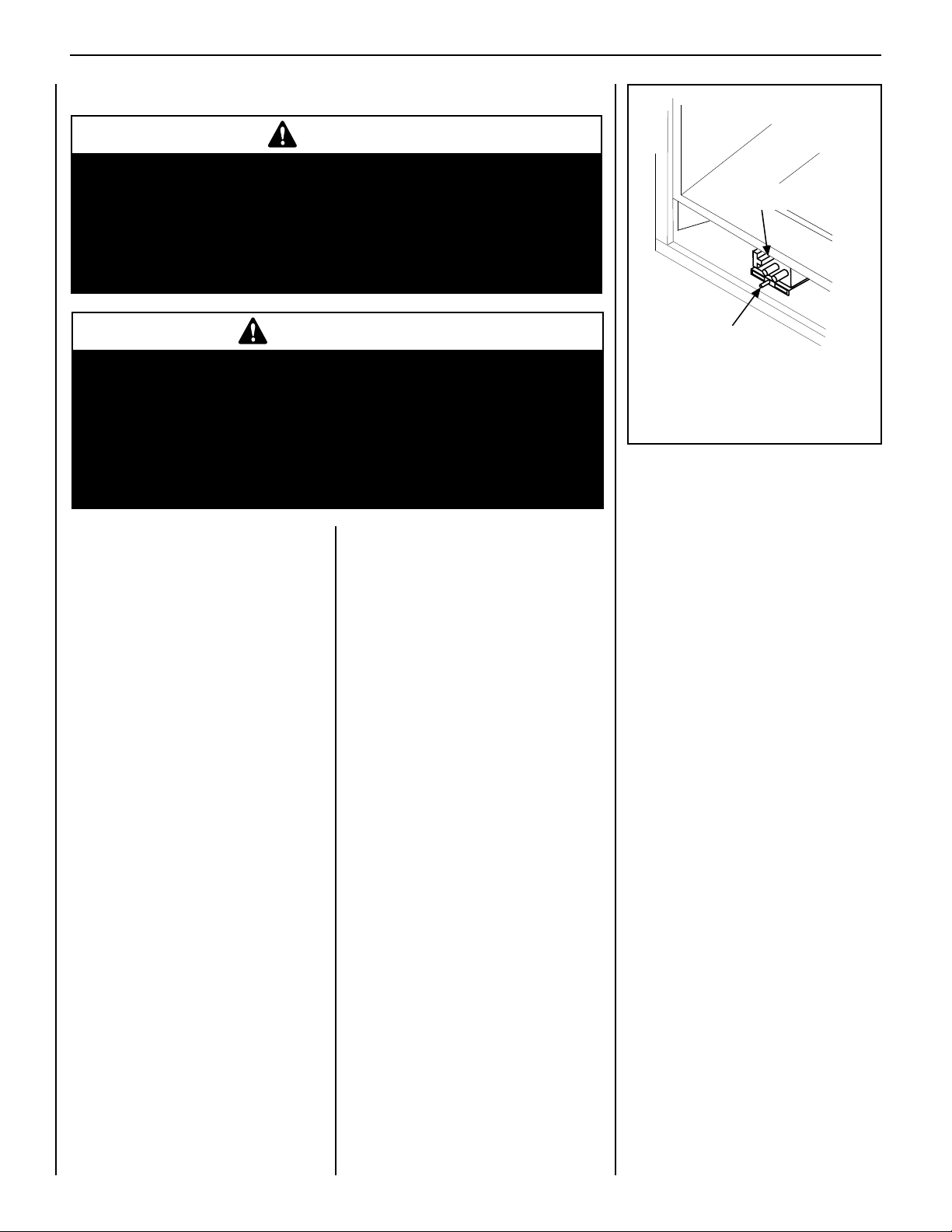
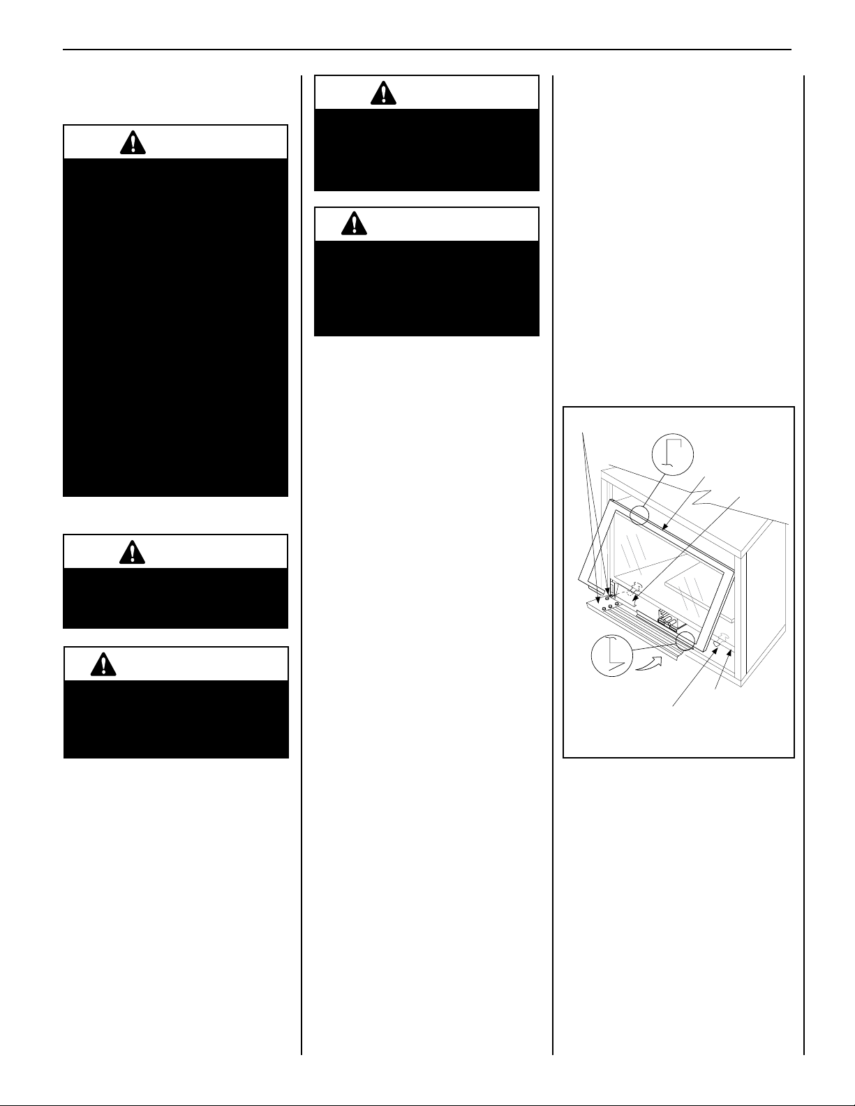
Removing Glass Enclosure Panels
(see Figure 4 )
Locate the two (2) latches at the top of the
control compartment and disengage them from
the door frame bottom vee-flange, pulling down
on their handles to open them.
Retrieve the glass door. Visually inspect the
gasket on the backside of the frame. Gasket
surface must be clean, free of irregularities
and seated firmly.
Position the door in front of the firebox opening
with the bottom of the door held away from the
fireplace (Figure 4 ). Hook the top flange of the
door frame over the top of the firebox frame.
Let the bottom of the door frame swing gently
in towards the fireplace ensuring that the gasket
seats evenly as the door frame draws shut.
Fasten the two latches located underneath the
firebox floor to the door's vee-flange. Close
both the latches securely.
AVERTISSEMENT
Ne pas utiliser l'appareil si le
panneau frontal en verre n'est
pas en place, est craqué ou
brisé.
Remove the top louver assembly or radiant
panel.
To access the glass door securing latches,
first open the lower control compartment door
(Figure 4 ) by pushing in simultaneously the left
and right top corners of the door. (The door
is hinged at the bottom.) Remove the bottom
compartment door by sliding the hinge pin,
located at the door’s left side, to the right until
it disengages from the left corner post hole.
Pull the door diagonally to the left, away from
the fireplace.
NOTE: DIAGRAMS & ILLUSTRATIONS ARE NOT TO SCALE.
Figure 4
11
Page 12

LENNOX HEARTH PRODUCTS • MERIT® PLUS DIRECT VENT GAS FIREPLACES (MPD33/35/40/45) • CARE AND OPERATION INSTRUCTIONS
Glowing Embers
INSTALL VERMICULITE, VOLCANIC
STONE, GLOWING EMBERS, AND LOGS
NOTE: Turn off all electricity to the appliance
before you install vermiculite, volcanic stone,
embers and logs. DO NOT attempt to install
the logs until the appliance installation has been
completed, the gas line connected and tested
for leaks and the initial burner operation has
been checked out.
Step 1. Remove the appliance front door (see
Removing Glass Enclosure panel on page 11.
Step 2. Install vermiculite and volcanic stone -
Sprinkle the vermiculite and volcanic stone in a
pleasing pattern. The vermiculite and volcanic
stone should be placed directly on top of the
firebox bottom, along the front and to the back
at the right and left sides of the burner. Position
any optional ceramic fiber liners before placing the vermiculite and volcanic stone. Logs
should be positioned after the vermiculite and
volcanic stone.
Note: This appliance is provided with enough
Glowing Embers for several applications, do
not feel compelled to use all that is in a new
bag. For best glowing effect, replace the ember
material annually. Replacement Glowing Embers are available (Catalog Number 88L53).
Glowing Embers
Separate into Quarter
Size (separate) Pieces
Bag of Glowing
Embers (rockwool)
Figure 5
Step 3. Separate the Glowing Ember
(Rockwool) into pieces about the size of a
quarter (Figure 5 ). Keep the pieces fluffed up,
not matted. Distribute these pieces over the
front surface of the burner, as shown in Figure
6. Do not use more than is necessary. When
properly positioned, the Glowing Embers will
cover approximately 65% of the front burner
and with no appreciable gaps or openings.
Ensure that the main burner ports remain
uncovered by the ember material.
Figure 6
Step 4. Placement of Logs -
All top logs that rest on lower logs, do so over
notches, indents or nubs. Proper log placement
is critical to prevent sooting. Logs should be
placed in the gaps between the flame peaks and
should be positioned so they do not impinge
the flames.
Step 5. Position the individual logs as shown
in Figures 7 and 8. Logs should be placed in
the order shown. All logs that have notches
to fit over the grate tines should be positioned
with these notches directly against the grate.
Handle logs carefully to prevent breakage.
Proper log placement is critical to encourage
outstanding flame appearance and prevent
sooting. When positioned properly as shown,
logs will be positioned between flame peaks
and will not impinge any flames.
Refer to Figure 7 for EDV3530 Series appliances and to Figure 8 for EDV4035 & EDV4540
Series appliances.
REFERENCE
Firebox Accessories / Parts
Cat. No. Model No. Description
88L53 FGE Bag of Glowing Embers
80L42 FDVS
H3696
Bag of Decorative
Volcanic Stone
— Bag of Vermiculite
WARNING
• DO NOT attempt to install the
logs until the appliance installation has been completed, the gas
line connected and tested for leaks
and the initial burner operation
has been checked out.
•
The size and position of the log
set was engineered to give the
appliance a safe, reliable and
attractive flame pattern. Any
attempt to use a different log set
in the fireplace will void the warranty and will result in incomplete
combustion, sooting, and poor
flame quality.
•
Logs get very hot and will
remain hot up to one hour after gas
supply is turned off. Handle only
when logs are cool. Turn off all
electricity to the appliance before
you install grate, volcanic stone,
vermiculite, embers and logs.
•
This appliance is not designed
to burn wood. Any attempt to do so
could cause irreparable damage to
the appliance and prove hazardous
to your safety.
•
If logs are not installed
according to the log installation
instructions, flame impingement
and improper combustion could
occur and result in soot and/or
excessive production of carbon
monoxide (CO), a colorless,
odorless, toxic gas.
12
NOTE: DIAGRAMS & ILLUSTRATIONS ARE NOT TO SCALE.
Page 13

LENNOX HEARTH PRODUCTS • MERIT® PLUS DIRECT VENT GAS FIREPLACES (MPD33/35/40/45) • CARE AND OPERATION INSTRUCTIONS
MPD-3328 LOG PLACEMENT
Log
Number Description (Stamped #)
1
3
2
Position the individual logs as shown below. Logs should be placed
4
6
5
in the order shown. Position the rear log on the brackets at the
rear of the firebox with the log's notches directly over the brackets.
Position the right log (log no. 3) by inserting the pin from the rear
log into the hole on its upper end. Place the left log and then the
smaller left and right top logs. All logs that have notches to fit over
the grate tines should be positioned with these notches directly
against the grate. All top logs that rest on lower logs, do so over
flattened mounting faces in the bottom logs.
1 Log, Rear (39-12)
2 Log, Left (39-1)
3 Log, Right (39-2)
4 Log, Top Center (39-13)
5 Log, Top/Left (39-3 )
6 Log, Top/Right (39-4)
Catalog Number for the entire log set: 24M15
Proper log and twig placement is critical to encourage outstanding
flame appearance and prevent sooting.
1
4
3
2
5
6
Figure 7
NOTE: DIAGRAMS & ILLUSTRATIONS ARE NOT TO SCALE.
13
Page 14

LENNOX HEARTH PRODUCTS • MERIT® PLUS DIRECT VENT GAS FIREPLACES (MPD33/35/40/45) • CARE AND OPERATION INSTRUCTIONS
MPD-3530 LOG PLACEMENT
Log
1
3
2
Number Description (Stamped #)
1 Log, Rear (39-5)
2 Log, Left (39-1)
3 Log, Right (39-2)
4 Log, Top Center (39-6)
5 Log, Top/Left (39-3)
6 Log, Top/Right (39-4)
Catalog Number for the entire log set: 24M22
4
5
6
Position the individual logs as shown below. Logs should be placed
in the order shown. Position the rear log on the brackets at the
rear of the firebox with the log's notches directly over the brackets.
Position the right log (log no. 3) by inserting the pin from the rear
log into the hole on its upper end. Place the left log and then the
smaller left and right top logs. All logs that have notches to fit over
the grate tines should be positioned with these notches directly
against the grate. All top logs that rest on lower logs, do so over
flattened mounting faces in the bottom logs.
Proper log and twig placement is critical to encourage outstanding
flame appearance and prevent sooting.
1
4 3
14
2
5
6
Figure 8
NOTE: DIAGRAMS & ILLUSTRATIONS ARE NOT TO SCALE.
Page 15

LENNOX HEARTH PRODUCTS • MERIT® PLUS DIRECT VENT GAS FIREPLACES (MPD33/35/40/45) • CARE AND OPERATION INSTRUCTIONS
MPD-4035 AND MPD-4540 LOG PLACEMENT
Log
1
2
3
Number Description (Stamped #)
1 Log, Center (39-8)
2 Log, Rear (138)
3 Log, Right (39-10)
4 Log, Left (39-9)
5 Log, Top/Left (39-11)
6 Log, Top/Right (39-11)
Catalog Number for the entire log set: 24M25
4
5
6
Position the individual logs as shown below. Logs should be placed
in the order shown. Position the center log on the burner first, then
place the glowing embers as shown in Figure 6. Place the rear
log, both the right and left, and then the smaller left and right top
logs. All logs that have notches to fit over the grate tines should
be positioned with these notches directly against the grate. All top
logs that rest on lower logs, do so over flattened mounting faces
in the bottom logs.
Proper log and twig placement is critical to encourage outstanding
flame appearance and prevent sooting.
1
4
3
2
5
Figure 9
NOTE: DIAGRAMS & ILLUSTRATIONS ARE NOT TO SCALE.
6
15
Page 16

LENNOX HEARTH PRODUCTS • MERIT® PLUS DIRECT VENT GAS FIREPLACES (MPD33/35/40/45) • CARE AND OPERATION INSTRUCTIONS
BURNER ADJUSTMENTS
(QUALIFIED TECHNICIANS ONLY)
Flame Appearance and Sooting
Proper flame appearance is a flame which is
blue at the base and becomes yellowish-orange
in the body of the flame.
When the appliance is first lit, the entire flame
may be blue and will gradually turn yellowishorange during the first 15 minutes of operation.
If the flame remains blue, or if the flame is
orange with evidence of sooting (black tip), the
air shutter opening may need to be adjusted.
If the air shutter opening is closed too far,
sooting may develop. Sooting is indicated by
black puffs developing at the tips of very long
orange flames. Sooting results in black deposits
forming on the logs, appliance inside surfaces
and on exterior surfaces adjacent to the vent
termination.
Sooting is caused by incomplete combustion
in the flames and lack of combustion air entering the air shutter opening. To achieve a warm
yellowish-orange flame with an orange body
that does not soot, the shutter opening must be
adjusted between these two extremes.
Figure 10 : MPD-3328
Air Shutter Adjustment Guidelines
• If there is smoke or soot present, first check
the log set positioning to ensure that the
flames are not impinging on any of the logs.
If the log set is properly positioned and a
sooting condition still exists, then the air
shutter opening should be increased.
• The more offsets in the vent system, the larger
the air shutter opening will need to be.
• An appliance operated with the air shutter
opened too far, may have flames that appear
blue and transparent. These weak, blue and
transparent flames are termed anemic.
• Propane models may exhibit flames which
candle or appear stringy. If this is present
and persists, adjust the air shutter to a more
closed position, then operate the appliance
for a few more minutes to ensure that the
flame normalizes and the flames do not
appear sooty.
The following chart is provided to aid you in
achieving the correct air shutter adjustment
for your installation.
Air Shutter Adjustment Guidelines:
Amount of
Primary Air
If air shutter is
closed too far
If air shutter is
open too far
Flame
Color
Flame will
be orange
Flame will
be blue
16
Figure 11: MPD-3530
Figure 12: MPD-4035 and MPD-4540
Air Shutter
Adjustment
Air shutter
gap should be
increased
Air shutter
gap should be
decreased
NOTE: DIAGRAMS & ILLUSTRATIONS ARE NOT TO SCALE.
Page 17

LENNOX HEARTH PRODUCTS • MERIT® PLUS DIRECT VENT GAS FIREPLACES (MPD33/35/40/45) • CARE AND OPERATION INSTRUCTIONS
MILLIVOLT
Thermocouple
Hood Igniter Rod
3/8" Min
(9 mm)
Thermopile
Pilot
Nozzels
ELECTRONIC
Proper Flame
Adjustment
Pilot
Nozzle
3/8 To 1/2 Inch
(9 mm to 13 mm)
Ground
Electrode
Flame Rod
Hot Surface
Igniter
Adjustment Rod Up
(Fully Open Position)
Air Shutter
Burner Tube
Adjusting Set Screw
Adjustment Rod Down
(minimum air
opening position)
WARNING
• Air shutter adjustment should
only be performed by a
qualified professional service technician.
• Ensure front glass panel is
in place and sealed during
adjustment.
CAUTION
• Soot will be produced if
the air shutter is closed too
much. Any damage due
to sooting, resulting from
improperly setting the air
shutter, is not covered under
the warranty.
• The air shutter door and
nearby appliance surfaces
are HOT. Exercise caution to
avoid injury while adjusting
flame appearance.
BURNER FLAME ADJUSTMENTS
1. Refer to Figures 10, 11, and 12 for proper
flame appearance. To adjust the flame, rotate
the adjustment rod toward the back or toward
the front of the fireplace (rod located in the
lower control area). Position the air shutter
to the factory setting as shown in the table
in Figure 13.
2. Light appliance (follow lighting procedure
on lighting label in control compartment or
in this Care and Operation Instructions).
3. Allow the burner to operate for at least 15
minutes while observing the flame continuously to ensure that the proper flame appearance has been achieved. If the following
conditions are present, adjust accordingly.
• If flame appears weak or sooty, adjust
the air shutter, incrementally, to a more
open position until the proper flame
appearance is achieved.
• If flame remains blue, adjust the air
shutter, incrementally, to a more closed
position until the proper flame appearance is achieved.
4. When satisfied that the burner flame appear-
ance is normal, turn the ON/OFF control
(unit-mounted or remote switch, depending
on your application) to the OFF position.
5. Reinstall the lower control access panel,
then proceed to finish the installation.
Millivolt Appliance Checkout
To light the burner, rotate the gas valve control
knob counterclockwise to the ON position
(“ON” will be at the top side of the valve).
Turn the ON/OFF control (unit-mounted or
remote switch, depending on your application)
to the ON position.
The pilot flame should be steady, not lifting
or floating. Flame should be blue in color with
traces of orange at the outer edge.
The top 3/8" (10 mm) at the pilot generator
(thermopile) and the top 1/8" minimum (tip)
of the quick drop out thermocouple should be
engulfed in the pilot flame.
The flame should project 1" (25 mm) beyond
the hood at all three ports (see Figure 14).
Replace logs if removed for pilot inspection.
Figure 14
8233-TDPM
8233-RDPM
0353-DPM
5304-DPM
0454-DPM
saG
epyT
.taN 23/1 )8.O(
.porP 61/3 )67.4(
.taN 23/1 )8.O(
.porP 61/3 )67.4(
.taN 23/1 )8.O(
.porP 61/3 )67.4(
.taN 8/1 )2.3(
.porP 2/1 )31(
.taN 8/1 )2.3(
.porP 2/1 )31(
GNITTES
sledoM
Figure 13
NOTE: DIAGRAMS & ILLUSTRATIONS ARE NOT TO SCALE.
Electronic Appliance Checkout
To light the burner, turn the integrated ON/OFF
switch (or optional switch, depending on your
application) to the ON position.
The pilot flame should engulf the flame rod, as
shown in Figure 15.
RIAYROTCAF
RETTUHS
)mm(sehcni
Figure 15
17
Page 18

LENNOX HEARTH PRODUCTS • MERIT® PLUS DIRECT VENT GAS FIREPLACES (MPD33/35/40/45) • CARE AND OPERATION INSTRUCTIONS
1. If any of the original wire as supplied must be replaced,
1. it must be replaced with Type AWM 105°C – 18 GA. wire.
2. 120V, 60Hz – Less than 3 amps.
BK
Transf.
120 V.
24 V
Factory Wired Field Wired
BL
Electronic Wiring Diagram (Honeywell)
Showing the Blower Wiring for the Optional
FBK-250 Kits
R
WH
BL
W
Gas Valve
B
R
IGNITER
BK
Schematic Representation Only
*ON/OFF Switch (Integral
with Gas Valve)
Optional
FBK-250
Module
*Leave the ON/OFF switch, which is integral
with the gas valve, in the ON position.
G
OPTIONAL APPLIANCE-MOUNTED ON/OFF SWITCH
OR OPTIONAL WALL SWITCH OR OPTIONAL THERMOSTAT
OR OPTIONAL REMOTE RECEIVER
PILOT
ASSEMBLY
OPT
BLOWER
Junction Box
White
Green
Red
Black
Neutral
Side of
Receptacle
Tab Intact
Green
Ground
Screw
Hot
Side of
Receptacle
Tab
Broken
Optional
Accessory
Switch
120 VAC - Black
neerG-dnuorG
etihW-lartueN
1. If any of the original wire as supplied must be replaced,
1. it must be replaced with Type AWM 105°C – 18 GA. wire.
2. 120V, 60Hz – Less than 3 amps.
BK
Transf.
120 V.
24 V
Factory Wired Field Wired
BL
Electronic Wiring Diagram (Honeywell)
Showing the Blower Wiring for the Optional
FBK-100 and FBK-200 Kits
R
W
BL
W
Gas Valve
B
R
IGNITER
BK
*Blower speed control switch is provided in FBK200 blower kit.
Schematic Representation Only
**ON/OFF Switch (Integral
with Gas Valve)
**Leave the ON/OFF switch, which is integral
with the gas valve, in the ON position.
OPTIONAL APPLIANCE-MOUNTED ON/OFF SWITCH
OR OPTIONAL WALL SWITCH
OR OPTIONAL THERMOSTAT
OR OPTIONAL REMOTE RECEIVER
G
OPT
BLOWER
PILOT
ASSEMBLY
Junction Box
White
Green
Red
Black
Neutral
Side of
Receptacle
Tab Intact
Green
Ground
Screw
Hot
Side of
Receptacle
Tab
Broken
120 VAC - Black
neerG-dnuorG
Optional
Accessory
Switch
etihW-lartueN
TP-TH
TP
TH
APPLIANCE- MOUNTED
ON/OFF SWITCH
(OPTIONAL)
BK/W(1)
BK/W(1)
WALL-MOUNTED ON/OFF SWITCH (OPTIONAL)
THERMOSTAT (OPTIONAL)
JUNCTION BOX
BLACK
W
GR
120 V
AC
WALL MOUNTED CONFIGURATION FOR FAN SWITCH (OPTIONAL)
BK
R
WIRING DIAGRAM MILLIVOLT GAS VALVES
THERMOPILE
GAS VALVE
FAN
(OPTIONAL)
WIRING DIAGRAMS
Wiring diagrams are provided here for reference
purposes only. This information is also provided
on schematics attached directly to the appliance
on a pullout panel located within the control
compartment.
CAUTION: LABEL ALL WIRES PRIOR TO DISCONNECTION WHEN SERVICING
CONTROLS. WIRING ERRORS CAN CAUSE IMPROPER AND DANGEROUS
APPLIANCE OPERATION.
ORDERING REPLACEMENT PARTS
A complete parts list is found at the end of
this manual. Use only parts supplied from the
18
manufacturer.
With proper care and maintenance, your appli-
ance will provide many years of enjoyment. If
you should experience any problem, first refer
to the troubleshooting guide in this manual. If
problem persists, contact your Lennox Hearth
Products dealer or distributor.
Normally, all parts should be ordered through
your Lennox Hearth Products distributor or dealer.
Parts will be shipped at prevailing prices at
time of order.
When ordering repair parts, always give the
following information:
1. The model number of the appliance.
2. The serial number of the appliance.
3. The part number.
4. The description of the part.
5. The quantity required.
6. The installation date of the appliance.
If you encounter any problems or have any
questions concerning the installation or application of this system, please contact your
dealer or distributor.
LENNOX HEARTH PRODUCTS
1508 Elm Hill Pike, Suite 108
Nashville, TN 37210
visit us at www.Lennox.com
1-800-9-LENNOX
PRODUCT REFERENCE INFORMATION
We recommend that you record the important
reference information about your fireplace in
the space provided below.
Please call Lennox Hearth Products for the
phone number of your nearest Lennox Hearth
Products dealer who will answer your questions
or address your concerns.
Fireplace Model Number ________________________________________________
Fireplace Serial Number _________________________________________________
Date Installed _________________________________________________________
Type of Gas Used in Fireplace ____________________________________________
Dealer Name _________________________________________________________
NOTE: DIAGRAMS & ILLUSTRATIONS ARE NOT TO SCALE.
Page 19

LENNOX HEARTH PRODUCTS • MERIT® PLUS DIRECT VENT GAS FIREPLACES (MPD33/35/40/45) • CARE AND OPERATION INSTRUCTIONS
(FBK-200 Models Only)
Fireplace Shipping Weights/Volumes
Cat.
No.
H7785 MPDR-3328CNM-B 98 lb. 13.1 cu. ft.
H7786 MPDR-3328CPM-B 98 lb. 13.1 cu. ft.
H7787 MPDR-3328CNE-B 98 lb. 13.1 cu. ft.
H7782 MPDT-3328CNM-B 98 lb. 13.1 cu. ft.
H7783 MPDT-3328CPM-B 98 lb. 13.1 cu. ft.
H7784 MPDT-3328CNE-B 98 lb. 13.1 cu. ft.
H0804 MPD-3530CNM-B 113 lb. 15.8 cu. ft.
H7789 MPD-3530CPM-B 113 lb. 15.8 cu. ft.
H1939 MPD-3530CNE-B 113 lb. 15.8 cu. ft.
H0805 MPD-4035CNM-B 147 lb. 20.2 cu. ft.
H7790 MPD-4035CPM-B 147 lb. 20.2 cu. ft.
H1940 MPD-4035CNE-B 147 lb. 20.2 cu. ft.
H0805 MPD-4540CNM-B 160 lb. 23.0 cu. ft.
H7790 MPD-4540CPM-B 160 lb. 23.0 cu. ft.
H1940 MPD-4540CNE-B 160 lb. 23.0 cu. ft.
Model
Ship.
Weight
Ship.
Volume
Standard Remote Control System
The Model RCL (Standard) Remote Control
System features a simple ON/OFF control
function for the fireplace. Includes a hand-held
transmitter, a remote receiver with wall-mount
coverplate, and all required hardware to install
the unit. The remote receiver can be wall- or
hearth-mounted.
Remote Control System (Standard) H0249 RCL
Deluxe Remote Control System
The Model RCL-T (Deluxe) Remote Control
System has all of the features of the standard
system along with an added easy-to-read LCD
screen that provides access to many enhancements, including battery power level indicator,
timer, mode of operation, thermostatic display
with room temperature in either F° or C°, flame
indicator, and clock. Fully programmable, the
Model RCL-T allows for command over nearly
all operational and temperature variables using
the hand-held remote control transmitter.
ACCESSORY COMPONENTS
Digital Wall Thermostat
The wall thermostat kit provides temperature control
for optimum comfort.
Wall Thermostat Kit, White H4635 DWTK
Touch-Up Paint Kit
Repair of minor scratches and discoloration of
the appliance painted surfaces may be accomplished with the touch-up paint kit.
Touch-Up Paint (Black) Kit 90L73 TPK-B
ON/OFF Wall Switch Kit
The ON/OFF wall switch may be used to control
the operation of the fireplace burner as an
alternative to the optional unit-mountable ON/
OFF rocker switch. Install the wall switch in a
convenient location near the fireplace.
ON/OFF Wall Switch Kit 85L87 FWSK
Unit-Mountable ON/OFF Rocker Switch Kit
(Millivolt systems only)
The rocker switch may be used to provide ON/
OFF operation as an alternative to the optional
wall switch. The rocker switch installs directly
in the gas valve mounting bracket (millivolt gas
valve-equipped fireplaces only).
Rocker Switch Kit 80L41 FRS
Remote Control System (Deluxe) H0251 RCL-STAT
Forced Air Blower Kit
The FBK-100 blower assembly provides constant-velocity forced-air circulation.
The FBK-200 blower assembly provides variable-speed forced-air circulation and includes
a wall-mountable variable-speed switch.
The FBK-250 blower assembly provides variable-speed forced-air circulation and includes
a unit-mountable variable-speed switch.
Forced Air Blower Kits:
Single Speed 80L84 FBK-100
Variable Speed with
wall-mountable switch 80L85 FBK-200
Variable Speed with
unit-mountable switch 80L86 FBK-250
NOTE: DIAGRAMS & ILLUSTRATIONS ARE NOT TO SCALE.
19
Page 20

LENNOX HEARTH PRODUCTS • MERIT® PLUS DIRECT VENT GAS FIREPLACES (MPD33/35/40/45) • CARE AND OPERATION INSTRUCTIONS
stiKemarFrooDeceiP-4
ledoM
.oN
.oNgolataC
.oNledoM
dehsiloP
ssarB
dehsurB
sselniatS
-DPM
8233
22L89
BP33KFD4
32L89
SB33KFD4
-DPM
0353
28M62
BP53KFD4
58M62
SB53KFD4
-DPM
5304
38M62
BP04KFD4
68M62
SB04KFD4
-DPM
0454
48M62
BP54KFD4
78M62
SB54KFD4
ACCESSORY COMPONENTS (continued)
stiKrevuoLdelbmessA
.oNgolataC
ledoM
.oN
dehsiloP
ssarB
-DPM
54M42
8233
-DPM
82L88
0353
-DPM
92L88
5304
-DPM
03L88
0454
These louvers are designed to replace the
standard charcoal louvers that are provided with
the appliance. The brass and brushed stainless
louver kits include six (6) louvers.
.oNledoM
dehsurB
sselniatS
64M42
BPM33RVL
SBM33RVL
23L88
2-BP53RVL
SB53RVL
33L88
2-BP04RVL
SB04RVL
43L88
2-BP54RVL
SB54RVL
stiKlenaPecaFnaelC
.oNledoM
8233-DPM
0353-DPM
5304-DPM
0454-DPM
.oNgolataC
.oNledoM
74M62
CM33DAR
63L88
2-C53DAR
73L88
2-C04DAR
83L88
2-C54DAR
Clean faced panel kits are available to convert the
standard louvered fireplaces to radiant models
which are more suited for finishing around the
firebox opening with non-combustible materials, such as tile.
stiKemarFrooDeceiP-2
.oNgolataC
ledoM
.oN
dehsiloP
ssarB
-DPM
8233
-DPM
0353
-DPM
5304
-DPM
0454
81L89
BP33KFD2
88M62
BP53KFD2
98M62
BP04KFD2
09M62
BP54KFD2
.oNledoM
dehsurB
sselniatS
91L89
SB33KFD2
19M62
SB53KFD2
29M62
SB04KFD2
39M62
SB54KFD2
20
The kits attach to the glass enclosure panel
without the use of hardware. The decorative
arch kits can not be used in conjunction with
the screen panel kit.
stiKrooDhcrA
.oNgolataC
.oNledoM
.oNledoM 8233-DPM 0353-DPM 5304-DPM 0454-DPM
dehsiloP
ssarB
hsiniF
dehsurB
sselniatS
hsiniF
50L89
BPC33KDA
26L89
SBC33KDA
34M62
BPMC53KDA
44M62
SBMC53KDA
NOTE: DIAGRAMS & ILLUSTRATIONS ARE NOT TO SCALE.
53L18
BPC04KDA
96L89
SBC04KDA
63L18
BPC54KDA
07L89
SBC54KDA
These kits are designed to attach directly to the
front face of the fireplace at the four edges of
the glass enclosure panel.
Page 21

LENNOX HEARTH PRODUCTS • MERIT® PLUS DIRECT VENT GAS FIREPLACES (MPD33/35/40/45) • CARE AND OPERATION INSTRUCTIONS
stiKrevuoLeceiP-2
ledoM
.oN
.oNgolataC
.oNledoM
dehsiloP
ssarB
dehsurB
sselniatS
-DPM
8233
90L89
BP33RVL2
80L89
SB33RVL2
-DPM
0353
50L69
BP53RVL2
90L69
SB53RVL2
-DPM
5304
60L69
BP04RVL2
01L69
SB04RVL2
-DPM
0454
70L69
BP54RVL2
11L69
SB54RVL2
ACCESSORY COMPONENTS (continued)
These louvers are designed to replace either
the middle charcoal louver of each louver set
or the charcoal louver in each set closest to the
glass enclosure panel.
stiKlenaPneercS
.oNledoM
8233-DPM
0353-DPM
5304-DPM
0454-DPM
These screen panels can be installed on the
glass enclosure panel to provided protection
from the hot glass surface. The screen panel
kits cannot be used in conjunction with either
of the arch door kits or door frame kits.
Termination Shroud
(Fits H1968)
Deluxe Termination
Guard (Fits 94L10)
Square Termination
Guard (Fits 94L10)
3-Piece Perimeter Finish Trim Kits
Models Catalog No. Model No.
MPD-3328 - Brass H0453 TK33PB3
MPD-3328 - Stainless H1813 TK33BS3
MPD-3328 - Black H4820 TK33C3
MPD-3530 - Brass 96K21 TK35PB3
MPD-3530 - Stainless H1815 TK35BS3
MPD-3530 - Black H4821 TK35C3
MPD-4035 - Brass 96K22 TK40PB3
MPD-4035 - Stainless H1816 TK40BS3
MPD-4035 - Black H4823 TK40C3
MPD-4540 - Brass 96K23 TK45PB3
MPD-4540 - Stainless H1817 TK45BS3
MPD-4540 - Black H4824 TK45C3
Termination Guard Kits
The vent termination guards may be used to
cover the vent termination on the exterior of the
home to minimize exposure to the hot surface
of the termination.
Termination Guard Kits (all models)
Cat. No. Model No. Description
H5820 4.5HTSK Termination Shroud
87L02 SV4.5HGS Termination Guard,
Deluxe
17M52 SV4.5HGS-1 Termination Guard,
Square
.oNgolataC
.oNledoM
40L89
33GH
84M62
M53GH
94M62
M04GH
4-Piece Perimeter Finish Trim Kits
Models Catalog No. Model No.
MPD-3530 - Brass 96K17 TK35PB4
MPD-4035 - Brass 96K18 TK40PB4
MPD-4540 - Brass 96K19 TK45PB4
05M62
M54GH
This kit contains trim pieces used to finish the
gaps between the wall board and the fireplace,
providing the appliance a perimeter highlight in
various finishes.
21
NOTE: DIAGRAMS & ILLUSTRATIONS ARE NOT TO SCALE.
Page 22

LENNOX HEARTH PRODUCTS • MERIT® PLUS DIRECT VENT GAS FIREPLACES (MPD33/35/40/45) • CARE AND OPERATION INSTRUCTIONS
stiKdooH
.oNledoM
.oNgolataC
.oNledoM
dehsiloP
ssarB
dehsurB
sselniatS
8233-DPM
01L89
BP33BE
11L89
SB33BE
0353-DPM
76K69
BP53BE
94L88
SB53BE
5304-DPM
86K69
BP04BE
05L88
SB04BE
0454-DPM
96K69
BP54BE
15L88
SB54BE
ACCESSORY COMPONENTS (continued)
Brickaded Panel Liner Kits
Models Catalog No. Model No.
MPD3328T H0912 MBLK33T
MPD3328R H0918 MBLK33R
MPD3530 H0913 MBLK35
MPD4035 H0914 MBLK40
MPD4540 H0915 MBLK45
The brickaded panel liner kits include ceramic
panels of the side walls, the rear and the baffle
of the firebox. The panels have brick-like features in relief.
These hood kits replace the standard hood that
comes with these fireplaces.
stiKlenaPneercShcrA
.oNledoM
8233-DPM
0353-DPM
5304-DPM
.oNgolataC
.oNledoM
2953H
IT33KPSAD
3953H
IT53KPSAD
4953H
IT04KPSAD
These screen panel kits can be installed on the
glass enclosure panel to prevent direct contact
with the hot glass surface. The panel kits add a
new design choice with a handsome textured
iron finish. The screen panel kits cannot be used
in conjunction with either of the arch door kits
or door frame kits.
22
NOTE: DIAGRAMS & ILLUSTRATIONS ARE NOT TO SCALE.
Page 23

LENNOX HEARTH PRODUCTS • MERIT® PLUS DIRECT VENT GAS FIREPLACES (MPD33/35/40/45) • CARE AND OPERATION INSTRUCTIONS
Style View Doors -
Style View Doors come in 4 beautiful styles. They are easy to install and will not require hardware to attach them to the standard
glass door frame. The door includes heavy duty magnet door latches and functional twin-pane doors.
Arch Design
Arch Pane Design
Square Pane Design
Square Design
ARCH DESIGN KITS
Cat. No. Model Description Model Series
H0858 AD35C 35” Arch Doors, Black
MPD3530
H0859 AD35TI 35” Arch Doors, Textured Iron
H0860 AD35SP 35” Arch Doors, Satin Pewter
H0861 AD35AB 35” Arch Doors, Antique Brass
H0862 AD40C 40” Arch Doors, Black
MPD4035
H0863 AD40TI 40” Arch Doors, Textured Iron
H0864 AD40SP 40” Arch Doors, Satin Pewter
H0865 AD40AB 40” Arch Doors, Antique Brass
H0866 AD45C 45” Arch Doors, Black
MPD4540
H0867 AD45TI 45” Arch Doors, Textured Iron
H0868 AD45SP 45” Arch Doors, Satin Pewter
H0869 AD45AB 45” Arch Doors, Antique Brass
ARCH PANE DESIGN KITS
H0930 APD35C 35” Arch Pane Doors, Black
MPD3530
H0931 APD35TI 35” Arch Pane Doors, Textured Iron
H0932 APD35SP 35” Arch Pane Doors, Satin Pewter
H0933 APD35AB 35” Arch Pane Doors, Antique Brass
H0934 APD40C 40” Arch Pane Doors, Black
MPD4035
H0935 APD40TI 40” Arch Pane Doors, Textured Iron
H0936 APD40SP 40” Arch Pane Doors, Satin Pewter
H0937 APD40AB 40” Arch Pane Doors, Antique Brass
H0938 APD45C 45” Arch Pane Doors, Black
MPD4540
H0939 APD45TI 45” Arch Pane Doors, Textured Iron
H0940 APD45SP 45” Arch Pane Doors, Satin Pewter
H0941 APD45AB 45” Arch Pane Doors, Antique Brass
H0950 SD40C 40” Sq. Doors, Black
MPD-4035
H0951 SD40TI 40” Sq. Doors, Textured Iron
H0952 SD40SP 40” Sq. Doors, Satin Pewter
H0953 SD40AB 40” Sq. Doors, Antique Brass
H0954 SD45C 45” Sq. Doors, Black
MPD4540
H0955 SD45TI 45” Sq. Doors, Textured Iron
H0956 SD45SP 45” Sq. Doors, Satin Pewter
H0957 SD45AB 45” Sq. Doors, Antique Brass
SQUARE PANE DESIGN KITS
H0962 SPD35C 35” Sq. Pane Doors, Black
MPD3530
H0963 SPD35TI 35” Sq. Pane Doors, Textured Iron
H0964 SPD35SP 35” Sq. Pane Doors, Satin Pewter
H0965 SPD35AB 35” Sq. Pane Doors, Antique Brass
H0966 SPD40C 40” Sq. Pane Doors, Black
MPD-4035
H0967 SPD40TI 40” Sq. Pane Doors, Textured Iron
H0968 SPD40SP 40” Sq. Pane Doors, Satin Pewter
H0969 SPD40AB 40” Sq. Pane Doors, Antique Brass
H0970 SPD45C 45” Sq. Pane Doors, Black
MPD4540
H0971 SPD45TI 45” Sq. Pane Doors, Textured Iron
H0972 SPD45SP 45” Sq. Pane Doors, Satin Pewter
H0973 SPD45AB 45” Sq. Pane Doors, Antique Brass
SQUARE DESIGN KITS
H0946 SD35C 35” Sq. Doors,Black
MPD3530
H0947 SD35TI 35” Sq. Doors, Textured Iron
H0948 SD35SP 35” Sq. Doors, Satin Pewter
H0949 SD35AB 35” Sq. Doors, Antique Brass
ACCESSORY COMPONENTS (continued)
NOTE: DIAGRAMS & ILLUSTRATIONS ARE NOT TO SCALE.
23
Page 24

LENNOX HEARTH PRODUCTS • MERIT® PLUS DIRECT VENT GAS FIREPLACES (MPD33/35/40/45) • CARE AND OPERATION INSTRUCTIONS
ACCESSORY COMPONENTS (continued)
Style View Doors Continued -
Style View Doors also come in a Tall Arch Pane Design. Two distinctive grille kits, the “Crescents” and “Sunrise” design, are
also offered seperately. They are easy to install and will not require hardware to attach them to the standard glass door
frame. The door includes heavy duty magnet door latches and functional twin-pane doors.
TALL ARCH PANE DOORS
Cat. No. Model Description Model Series
Tall Arch Pane Door
H3525 TAPD35C 35” Arch Pane Doors, Black
TAPD35SP
H3527 35” Arch Pane Doors, Satin Pewter
H3529 TAPD40C
TAPD40SP
H3531
H3533 TAPD45C
TAPD45SP
H3535
40” Arch Pane Doors, Black
40” Arch Pane Doors, Satin Pewter
45” Arch Pane Doors, Black
45” Arch Pane Doors, Satin Pewter
MPD3530
MPD4035
MPD4540
Crescents Grille Kits
“Crescents” Grille Kits
Cat. No. Model Description Model Series
H3541 CUGK35C 35” Crescents Upper Grille Kit, Black
CUGK35SP
H3543
H3545 CLGK35C 35” Crescents Lower Grille Kit, Black
H3547
CLGK35SP
H3549 CUGK40C 40” Crescents Upper Grille Kit, Black
CUGK40SP
H3551
H3553 CLGK40C 40” Crescents Lower Grille Kit, Black
H3555
CLGK40SP
H3557 CUGK45C 45” Crescents Upper Grille Kit, Black
CUGK45SP
H3559
H3561 CLGK45C 45” Crescents Lower Grille Kit, Black
H3563
CLGK45SP
35” Crescents Upper Grille Kit, Satin Pewter
35” Crescents Lower Grille Kit, Satin Pewter
40” Crescents Upper Grille Kit, Satin Pewter
40” Crescents Lower Grille Kit, Satin Pewter
45” Crescents Upper Grille Kit, Satin Pewter
45” Crescents Lower Grille Kit, Satin Pewter
MPD3530
MPD4035
MPD4540
Sunrise Grille Kits
“Sunrise” Grille Kits
Cat. No. Model Description Model Series
H3565 SUGK35C 35” Sunrise Upper Grille Kit, Black
SUGK35SP
H3567
H3569 SLGK35C 35” Sunrise Lower Grille Kit, Black
H3571
SLGK35SP
H3573 SUGK40C 40” Sunrise Upper Grille Kit, Charcoal
SUGK40SP
H3575
H3577 SLGK40C 40” Sunrise Lower Grille Kit, Black
H3579
SLGK40SP
H3581 SUGK45C 45” Sunrise Upper Grille Kit, Black
SUGK45SP
H3583
H3585 SLGK45C 45” Sunrise Lower Grille Kit, Black
H3587
SLGK45SP
35” Sunrise Upper Grille Kit, Satin Pewter
35” Sunrise Lower Grille Kit, Satin Pewter
40” Sunrise Upper Grille Kit, Satin Pewter
40” Sunrise Lower Grille Kit, Satin Pewter
45” Sunrise Upper Grille Kit, Satin Pewter
45” Sunrise Lower Grille Kit, Satin Pewter
MPD3530
MPD4035
MPD4540
24
NOTE: DIAGRAMS & ILLUSTRATIONS ARE NOT TO SCALE.
Page 25

LENNOX HEARTH PRODUCTS • MERIT® PLUS DIRECT VENT GAS FIREPLACES (MPD33/35/40/45) • CARE AND OPERATION INSTRUCTIONS
MAINTENANCE SCHEDULE
Annually (Before the onset of the Burning Season)
Maintenance Task Accomplishing Person Procedure
Inspecting/Cleaning Burner, Logs
and Controls
Check Flame Patterns and Flame Height
Inspecting/Cleaning Pilot and Burner
Checking Vent System
Appliance Checkout
Replacing Rockwool Ember Materials
Qualified Service Technician
Qualified Service Technician
Qualified Service Technician
Qualified Service Technician
Qualified Service Technician
Homeowner/Qualified Services Technician
Inspect valve and ensure it is properly operating. Check piping for leaks. Vacuum the control
compartment, fireplace logs and burner area.
Refer to Figures 10 (MPD-3328), 11 (MPD-
3530) or 12 (MPD-4035 & 4540) on page 16 and
verify the flame pattern and height displayed by
the appliance conforms to the picture. Flames
must not impinge on the logs.
Refer to Figure 13 (SIT) or Figure 14 (Honeywell)
on page 17. Remove any surface build-up on
pilot and burner assembly. Wipe the pilot nozzles,
ignitor/flame rod and hood. Ensure the pilot flame
engulfs the flame sensor as shown.
Inspect the vent system at the top and at the
base (within the firebox) for signs of blockage
or obstruction. Look for any signs of dislocation
of the vent components.
Perform the appropriate appliance checkout
procedure detailed in this manual.
Remove old ember materials and vacuum the
rockwool placement area. Place new rockwool
as described in this document.
Periodically (After the Burning Season)
Maintenance Task Accomplishing Person Procedure
Cleaning Firebox Interior
Homeowner
Carefully remove logs, rockwool and decorative
volcanic stone and vermiculite. Vacuum out
interior of the firebox. Clean firebox walls and
log grate. Replace logs, Rockwool and volcanic
stone as detailed in this manual.
Check Flame Patterns and Flame Height
Homeowner
Refer to Refer to Figures 10 (MPD-3328), 11
(MPD-3530) or 12 (MPD-4035 & 4540) on
page 16 and verify the flame pattern and height
displayed by the appliance conforms to the
picture. Flames must not impinge on the logs.
Checking Vent System
Homeowner
Inspect the vent system at the top and at the
base (within the firebox) for signs of blockage
or obstruction. Look for any signs of dislocation
of the vent components.
Cleaning Front Glass Enclosure Panel
Homeowner
Clean as necessary following the directions
provided in this manual. DO NOT TOUCH OR
ATTEMPT TO CLEAN GLASS WHILE HOT.
NOTE: DIAGRAMS & ILLUSTRATIONS ARE NOT TO SCALE.
25
Page 26

LENNOX HEARTH PRODUCTS • MERIT® PLUS DIRECT VENT GAS FIREPLACES (MPD33/35/40/45) • CARE AND OPERATION INSTRUCTIONS
LIGHTING INSTRUCTIONS – MILLIVOLT GAS VALVE
FOR YOUR SAFETY, READ BEFORE LIGHTING
WARNING: If you do not follow these instructions exactly, a fire or explosion may result, causing
property damage, personal injury, or loss of life.
A. This appliance has a pilot which must be lighted by a piezo
igniter. When lighting the pilot, follow these instructions
exactly.
B. BEFORE LIGHTING smell all around the appliance area for
gas. Be sure to smell next to the floor because some gas is
heavier than air and will settle on the floor.
WHAT TO DO IF YOU SMELL GAS:
• Do not try to light any appliance.
• Do not touch any electric switch; do not use any phone in your
building.
LIGHTING INSTRUCTIONS
1. STOP! Read the safety information above on this label.
2. (If applicable) Set the thermostat to lowest setting. Turn wall on/off
switch, unit mounted on/off switch or remote control switch "OFF."
3. Turn OFF all electric power to the appliance.
4. Access the control compartment.
5. Push in gas control knob slightly and turn clockwise to "OFF."
NOTE: Knob cannot be turned from "PILOT" to "OFF" unless knob is
pushed in slightly. Do Not force.
6. Wait five (5) minutes to clear out any gas. Then smell for gas,
including near the floor. If you smell gas, STOP! Follow "B" in the
safety information above on this label. If you don't smell gas, go to the
next step.
7. Find pilot - located in firebox on the same plane as the top of the burner.
8. Turn knob on gas control counterclockwise to "PILOT."
9. Push in control knob all the way and hold in. Immediately light the pilot
by triggering the piezo igniter (pushing the button) until pilot lights.
Continue to hold the control knob in for about 1-1/2 minutes after the
pilot is lit. Release knob and it will pop back up. Pilot should remain
lit. If it goes out, repeat steps 5 through 9.
• If knob does not pop up when released, stop and immediately call
your service technician or gas supplier.
• Immediately call your gas supplier from a neighbor’s phone.
Follow the gas supplier’s instructions.
• If you cannot reach your gas supplier, call the fire department.
C. Use only your hand to push in or turn the gas control knob.
Never use tools. If the knob will not push in or turn by hand,
don’t try to repair it, call a qualified service technician. Force
or attempted repair may result in a fire or explosion.
D. Do not use this appliance if any part has been under water.
Immediately call a qualified service technician to inspect the
appliance and to replace any part of the control system and
any gas control which has been under water.
• If the pilot will not stay lit after several tries, turn the gas control
knob to "OFF" and call your service technician or gas supplier.
10. Turn gas control knob counterclockwise to "ON."
11. Close control compartment.
12. (If applicable) Turn on all electrical power to the appliance.
13. (If applicable) Set thermostat to desired setting. Turn wall on/off switch,
unit mounted on/off switch or remote control switch "ON."
SIT
Robertshaw
Honeywell
Gas Control Valves
T
O
L
I
N
O
T
O
L
I
P
F
F
OUT
IN
Gas Control Knobs
ON
PILOT
OFF
PILOT
H
I
O
L
P
O
W
L
it
O
H
I
HI
LO
IN OUT
F
T
F
O
O
L
I
P
N
O
Pilot Assemblies
TPTH TP TH
26
TO TURN OFF GAS TO APPLIANCE
1. (If applicable) Set the thermostat to lowest setting. Turn wall on/off
switch, unit mounted on/off switch or remote control switch "OFF."
2. Turn OFF all electric power to the appliance, if service is to be
performed.
3. Access the control compartment.
WARNING
HOT GLASS WILL CAUSE BURNS.
DO NOT TOUCH GLASS UNTIL COOLED.
NEVER ALLOW CHILDREN TO TOUCH GLASS.
P/N 62L2901_4
NOTE: DIAGRAMS & ILLUSTRATIONS ARE NOT TO SCALE.
4. Push in gas control knob slightly and turn clockwise to "OFF."
Do not force.
5. Close the main line gas shut-off valve.
6. Close control compartment.
Page 27

LENNOX HEARTH PRODUCTS • MERIT® PLUS DIRECT VENT GAS FIREPLACES (MPD33/35/40/45) • CARE AND OPERATION INSTRUCTIONS
INSTRUCTIONS D’ALLUMAGE – VANNE GAZ MILLIVOLT
POUR PLUS DE SÉCURITÉ, LIRE AVANT D’ALLUMER
AVERTISSEMENT. Quiconque ne respecte pas à la lettre les instructions dans la présente notice risque
de déclencher un incendie ou une explosion entraînant des dommages, des blessures ou la mort.
A.Cet appareil est muni d’une veilleuse qui doit être
allumée avec un allumeur piézo-électrique. Respectez les
instructions ci-dessous à la lettre.
B. AVANT L’ALLUMAGE: Avant d’allumer la veilleuse, reniflez
tout autour de l’appareil pour déceler une odeur de gaz.
Reniflez près du plancher, car certains gaz sont plus lourds
que l’air et peuvent s’accumuler au niveau du sol.
QUE FAIRE SI VOUS SENTEZ UNE ODEUR DE GAZ :
• Ne pas tenter d’allumer d’appareil.
• Ne touchez à aucun interrupteur ; ne pas vous servir des
téléphones se trouvant dans le bâtiment.
INSTRUCTIONS D’ALLUMAGE
1. ARRÊTEZ ! Lisez les instructions de sécurité sur la portion supérieure de
cette étiquette.
2. (Si applicable) Réglez le thermostat à la température la plus basse.
Tournez l’interrupteur murale, l’interrupteur sur l’unité ou le contrôle à
distance à "OFF. "
3. Coupez l’alimentation électrique de l’appareil.
4. Accédez au compartiment de contrôle.
5. Enfoncez légèrement le bouton de réglage du gaz et tournez-le dans le sens
des aiguilles d’une montre jusqu’à la position d’arrêt “OFF”.
Remarque: Il est impossible de tourner le bouton de “PILOT” à “OFF” à
moins qu’il ne soit légèrement enfoncé. Ne le forcez pas.
6. Attendre cinq (5) minutes pour laisser échapper tout le gaz. Reniflez tout
autour de l’appareil, y compris près du plancher, pour déceler une odeur
de gaz. Si vous sentez une odeur de gaz, ARRÊTEZ ! Passez à l’étape B des
instructions de sécurité sur la portion supérieure de cette étiquette. S’il n’y
a pas d’odeur de gaz, passez à l’étape suivante.
7. Trouver le pilote –
brûleur.
8. Tournez le bouton de contrôle sur la valve à gaz dans le sens antihoraire
vers "Pilote".
9. Enfoncez le bouton de réglage jusqu’au fond et gardez-le enfoncé. Allumez
immédiatement la veilleuse en déclenchant l’allume-gaz à étincelle (en
poussant le bouton) jusqu’à ce que la veilleuse s’enflamme. Continuez
de tenir le bouton de réglage enfoncé pendant environ 90 secondes après
l’allumage de la veilleuse. Relâchez le bouton et il sortira subitement. La
veilleuse devrait rester allumée. Si
inclusivement.
Situé dans l’âtre sur la même surface que le dessus du
elle s’éteint, répétez les étapes 5 à 8
• Appelez immédiatement votre fournisseur de gaz depuis un
voisin. Suivez les instructions du fournisseur.
• Si vous ne pouvez rejoindre le fournisseur, appelez le service
des incendies.
C. Ne pousser ou tourner la manette d’admission du gaz qu’à la
main. Ne jamais employer d’outil à cette fin. Si la manette
reste coincée, ne tentez pas de la réparer; appelez un
technicien qualifié. Quiconque tente de forcer la manette ou
de la réparer peut provoquer une explosion ou un incendie.
D. N’utilisez pas cet appareil s’il a été plongé dans l’eau, même
partiellement. Faites inspecter l’appareil par un technicien
qualifié et remplacez toute partie du système de contrôle et
toute commande qui ont été plongés dans l’eau.
• Si la manette ne se soulève pas d’elle-même lorsqu’on la relâche,
arrêter et appeler immédiatement un technicien qualifié ou le
fournisseur de gaz.
• Si la veilleuse ne reste pas allumée après plusieurs tentatives,
réglez la manette d’admission du gaz à la position OFF et appelez un
technicien qualifié ou le fournisseur de gaz.
10. Tournez le bouton de réglage du gaz en sens inverse des aiguilles d’une
montre jusqu’à sa position de marche “ON”.
11. Fermer le compartiment de contrôle.
12. (Si applicable) Mettez l’appareil sous tension.
13. (Si applicable) Réglez le thermostat à la température désirée.
l’interrupteur murale, l’interrupteur sur l’unité ou le contrôle à distance
à "ON."
SIT
Robertshaw
Honeywell
Vanne Gaz Millivolt
IN
Bouton de réglage du gaz
ON
PILOT
OFF
PILOT
H
I
O
L
T
O
L
I
P
N
O
T
O
W
L
O
it
L
I
P
O
F
F
H
I
OUT
HI
LO
IN OUT
F
T
F
O
O
L
I
P
N
O
Millivolt Pilot
TPTH TP TH
Tournez
COMMENT COUPER L’ADMISSION DE GAZ DE L’APPAREIL
1. (Si applicable) Réglez le thermostat à la température la plus basse. Tournez
l’interrupteur murale, l’interrupteur sur l’unité ou le contrôle à distance à
"OFF. "
2. Coupez l’alimentation électrique de l’appareil s’il faut procéder à l’entretien.
3. Accédez au compartiment de contrôle.
AVERTISSEMENT
UNE SURFACE VITRÉE CHAUDE PEUT CAUSER DES BRÛLURES.
LAISSER REFROIDIR LA SURFACE VITRÉE AVANT D'Y TOUCHER.
NE PERMETTEZ JAMAIS À UN ENFANT DE TOUCHER LA SURFACE VITRÉE.
P/N 62L3001_3
REMARQUE : LES SCHÉMAS ET LES ILLUSTRATIONS NE SONT PAS À L’ÉCHELLE
NOTE: DIAGRAMS & ILLUSTRATIONS ARE NOT TO SCALE.
4. Enfoncez légèrement le bouton de réglage du gaz et tournez-le dans le
sens des aiguilles d’une montre jusqu’à la position d’arrêt “OFF”.
Ne forcez pas le bouton.
5. Fermer la valve de gaz principale.
6. Fermer le compartiment de contrôle.
27
Page 28

LENNOX HEARTH PRODUCTS • MERIT® PLUS DIRECT VENT GAS FIREPLACES (MPD33/35/40/45) • CARE AND OPERATION INSTRUCTIONS
LIGHTING INSTRUCTIONS — ELECTRONIC
FOR YOUR SAFETY, READ BEFORE OPERATING
WARNING: If you do not follow these instructions exactly, a fire or explosion may result, causing
property damage, personal injury, or loss of life.
A. This appliance is equipped with an ignition device which
• Immediately call your gas supplier from a neighbor’s phone.
automatically lights the pilot. Do not try to light the pilot by
hand.
B. BEFORE OPERATING smell all around the appliance area for
• If you cannot reach your gas supplier, call the fire department.
C. Use only your hand to actuate the gas valve ON/OFF switch.
gas. Be sure to smell next to the floor because some gas is
heavier than air and will settle on the floor.
WHAT TO DO IF YOU SMELL GAS:
• Do not try to light any appliance.
D. Do not use this appliance if any part has been under water.
• Do not touch any electric switch; do not use any phone in your
building.
OPERATING INSTRUCTIONS
1. STOP! Read the safety information above on this label.
2. (If applicable) Set the thermostat to lowest setting. Turn
wall on/off switch, unit mounted on/off switch or remote
control switch "OFF."
3. Turn OFF all electric power to the appliance.
4. This appliance is equipped with an ignition device which
automatically lights the pilot. Do not try to light the pilot by
hand.
5. Access the control compartment.
6. Turn the ON/OFF switch, on the gas control valve, to "OFF."
Do not force.
7. Wait five (5) minutes to clear out any gas. If you smell gas,
STOP! Follow "B" in the safety information above on this
label. If you don't smell gas, go to the next step.
8. Turn the ON/OFF switch, on the gas control valve, to "ON."
Do not force.
9. Turn on all electrical power to the appliance.
10. (If applicable) Set thermostat to desired setting. Turn wall
11. Close control compartment.
12. If the appliance will not operate, follow the instructions
Follow the gas supplier’s instructions.
Never use tools. If the switch will not move by hand, don’t
try to repair it, call a qualified service technician. Force or
attempted repair may result in a fire or explosion.
Immediately call a qualified service technician to inspect the
appliance and to replace any part of the control system and
any gas control which has been under water.
on/off switch, unit mounted on/off switch or remote control
switch "ON."
under "To Turn Off Gas To Appliance," and call your service
technician or gas supplier.
ON / OFF Switch
N O
F F O
L O R T N O C
G I N T I E R
Honeywell Gas Control Valve
N I
I
S
P
Electronic Pilot Assembly
28
TO TURN OFF GAS TO APPLIANCE
1. (If applicable) Set the thermostat to lowest setting. Turn wall
on/off switch, unit mounted on/off switch or remote control
switch "OFF."
2. Turn "OFF" all electric power to the appliance if service is to
be performed.
WARNING
HOT GLASS WILL CAUSE BURNS.
DO NOT TOUCH GLASS UNTIL COOLED.
NEVER ALLOW CHILDREN TO TOUCH GLASS.
P/N 62L2701_4
NOTE: DIAGRAMS & ILLUSTRATIONS ARE NOT TO SCALE.
3. Access the control compartment.
4. Turn the ON/OFF switch, on the gas control valve, to "OFF."
Do not force.
5. Close the main line gas shut-off valve.
6. Close control compartment.
Page 29

LENNOX HEARTH PRODUCTS • MERIT® PLUS DIRECT VENT GAS FIREPLACES (MPD33/35/40/45) • CARE AND OPERATION INSTRUCTIONS
INSTRUCTIONS D’ALLUMAGE — ELECTRONIC
POUR PLUS DE SÉCURITÉ, LIRE AVANT DE METTRE EN MARCHE
AVERTISSEMENT. Quiconque ne respecte pas à la lettre les instructions dans la présente notice risque
de déclencher un incendie ou une explosion entraînant des dommages, des blessures ou la mort.
A. Cet appareil est muni d’un dispositif d’allumage qui allume
automatiquement la veilleuse. Ne tentez pas d’allumer la
veilleuse manuellement.
B. AVANT DE FAIRE FONCTIONNER, reniflez tout autour de
l’appareil pour déceler une odeur de gaz. Reniflez près
du plancher, car certains gaz sont plus lourds que l’air et
peuvent s’accumuler au niveau du sol.
QUE FAIRE SI VOUS SENTEZ UNE ODEUR DE GAZ :
• Ne pas tenter d’allumer d’appareil.
• Ne touchez à aucun interrupteur; ne pas vous servir des
téléphones se trouvant dans le bâtiment.
• Appelez immédiatement votre fournisseur de gaz depuis un
voisin. Suivez les instructions du fournisseur.
INSTRUCTIONS DE MISE EN MARCHE
1. ARRÊTEZ ! Lisez les instructions de sécurité sur la portion
supérieure de cette étiquette.
2. (Si applicable) Réglez le thermostat à la température la plus
basse. Tournez l’interrupteur murale, l’interrupteur sur l’unité ou le
contrôle à distance à "OFF."
3. Coupez l’alimentation électrique de l’appareil.
4. Cet appareil est muni d’un dispositif d’allumage qui allume
automatiquement la veilleuse. Ne tentez pas d’allumer la veilleuse
manuellement.
5. Accédez au compartiment de contrôle.
6. Tournez l’interrupteur sur la valve de contrôle à "OFF." Ne pas
forcer.
7.
Attendre cinq (5) minutes pour laisser échapper tout le
gaz. Reniflez tout autour de l’appareil, y compris près du
plancher, pour déceler une odeur de gaz. Si vous sentez
une odeur de gaz, ARRÊTEZ ! Passez à l’étape B des
instructions de sécurité sur la portion supérieure de cette
étiquette. S’il n’y a pas d’odeur de gaz, passez à l’étape
suivante.
• Si vous ne pouvez rejoindre le fournisseur, appelez le service
des incendies.
C. N'utilisez que votre main pour manipuler l'interrupteur
"ON/OFF" de la valve á gaz. N'utilisez jamais d'outils. Si
l'interrupteur ne bouge pas manuel lement, n'essayez pas de
le réparer. Communiquez immédiatement avec un technicien
de service qualifié. Toute tentative pour forcer l'interrupteur
ou le réparer, risquerait de provoquer un incendie ou une
explosion.
D. N’utilisez pas cet appareil s’il a été plongé dans l’eau, même
partiellement. Faites inspecter l’appareil par un technicien
qualifié et remplacez toute partie du système de contrôle et
toute commande qui ont été plongés dans l’eau.
8. Tournez l’interrupteur sur la valve de contrôle à "ON." Ne pas forcer.
9. Mettez l’appareil sous tension.
10.(Si applicable) Réglez le thermostat à la température désirée.
Tournez l’interrupteur murale, l’interrupteur sur l’unité ou le
contrôle à distance à "ON."
11. Fermer le compartiment de contrôle.
12. Si l’appareil ne se met pas en marche, suivez les instructions
intitulées « Comment couper l’admission de gaz de l’appareil » et
appelez un technicien qualifié ou le fournisseur de gaz.
Commutateur ON/OFF
N O
F F O
L O R T N O C
G I N T I E R
Valve Honeywell
N I
I
S
P
Veilleuse de
l’appareil électronique
COMMENT COUPER L’ADMISSION DE GAZ DE L’APPAREIL
1. (Si applicable) Réglez le thermostat à la température la plus basse.
Tournez l’interrupteur murale, l’interrupteur sur l’unité ou le contrôle
à distance à "OFF."
2. Coupez l’alimentation électrique de l’appareil s’il faut procéder à
l’entretien.
AVERTISSEMENT
UNE SURFACE VITRÉE CHAUDE PEUT CAUSER DES BRÛLURES.
LAISSER REFROIDIR LA SURFACE VITRÉE AVANT D'Y TOUCHER.
NE PERMETTEZ JAMAIS À UN ENFANT DE TOUCHER LA SURFACE VITRÉE.
P/N 62L2801_3
REMARQUE : LES SCHÉMAS ET LES ILLUSTRATIONS NE SONT PAS À L’ÉCHELLE
NOTE: DIAGRAMS & ILLUSTRATIONS ARE NOT TO SCALE.
3. Accédez au compartiment de contrôle.
4. Tournez l’interrupteur sur la valve de contrôle à ‘’OFF.’’ Ne pas forcer.
5. Fermer la valve de gaz principale.
6. Fermer le compartiment de contrôle.
29
Page 30

LENNOX HEARTH PRODUCTS • MERIT® PLUS DIRECT VENT GAS FIREPLACES (MPD33/35/40/45) • CARE AND OPERATION INSTRUCTIONS
TROUBLESHOOTING GUIDE: MILLIVOLT GAS CONTROL SYSTEM
Note: Before troubleshooting the gas control system, make sure the external gas shut off valve (located at gas supply inlet) is in
the “ON” position.
Important: Valve system troubleshooting should only be accomplished by a qualified service technician.
1. Spark ignitor will not light
pilot after repeated triggering
of ignitor button.
2. Pilot will not stay lit after
carefully following the lighting instructions.
3. Pilot burning, no gas to
burner, Valve knob “ON,”
Wall Switch “ON.”
POSSIBLE CAUSES
A. Defective ignitor
(no spark at electrode).
B. Defective or misaligned electrode
at pilot (spark at electrode).
C. Gas supply pressure errant.
D. Pilot orifice plugged.
A. Defective pilot generator
(thermocouple).
A. Wall switch or wires defective.
CORRECTIVE ACTIONSYMPTOM
Check for spark at electrode and pilot; if no spark and electrode
wire is properly connected, replace ignitor.
Using a match, light pilot. If pilot lights, turn off pilot and trigger the ignitor button again. If pilot lights, an improper gas
mixture caused the bad lighting and a longer purge period is
recommended. If pilot will not light – check gap at electrode and
pilot – should be 1/8" to have a strong spark. If gap measures
1/8", replace pilot (Figure 14 on page 17).
Check inlet gas pressure. It should be within the limits as
marked on the rating plate.
Clean or replace pilot orifice.
Check pilot flame, it must impinge on thermocouple (Figure
14 on page 17). Clean and/or adjust pilot for maximum flame
impingement on thermocouple. Ensure that the connection
between the valve and thermocouple are tight and secure.
Check wall switch and wires for proper connections. Jumper
wire across terminals at wall switch, if burner comes on, replace defective wall switch. If okay, jumper wires across wall
switch wires at valve, if burner comes on, wires are faulty or
connections are bad.
30
4. Frequent pilot/burner outage
problem.
B. Thermopile may not be generating
sufficient millivoltage.
C. Plugged burner orifice.
A. Pilot flame may be too low or
blowing (high) causing the pilot/
valve safety to drop out.
Check thermopile with millivolt meter. Take reading at thermopile terminals of gas valve. Should read 325 millivolts minimum
with optional wall switch “OFF.” Replace faulty thermopile if
reading is below specified minimum.
Check burner orifice for stoppage and remove.
Clean and/or adjust pilot flame for maximum flame impingement on thermocouple (Figure 14 on page 17).
Page 31

LENNOX HEARTH PRODUCTS • MERIT® PLUS DIRECT VENT GAS FIREPLACES (MPD33/35/40/45) • CARE AND OPERATION INSTRUCTIONS
• Turn Off Gas Supply
• Assure Valve Switch Is In ON Position
• Disconnect Control Harness
• Set Thermostat To Call For Heat
• Check For Proper Voltage At Control Harness
(See Insert A). Voltage Should Be 24V
Between Thermostat Or Pressure Switch
And 24V Common And 24V Hot.
• Line Voltage Power
• Low Voltage Transformer
• Limit Controller
• Thermostat
• Wiring
2
CHECK
START
NO
• Plug Control Harness Into Valve. Wait For
Internal Check Delay.
YES
• Igniter Warms Up And Glows Red.
• With Pilot Burner Cable Connected, Measure
Voltage At Valve HSI Element Output. 24V
Nominal. (See Insert B)
NO
• Replace Igniter/Flame Rod Assembly.
YES
• Replace Valve.
NO
• Turn On Gas Supply. • Pilot Burner Lights.
• Check That Pilot Gas Is Flowing. Wait To
Assure Plot Gas Tubing Is Purged. Recycle
Call For Heat If Necessary.
NO
YES
NO
YES
YES
1
• Measure Voltage Between 24V Hot And 24V Common
Leads To Valve Control. Must Measure At Least 19.5
VAC With Igniter Powered (See Insert A). To Identify
Proper Lead, This Check Must Be Done With The
Valve Control Connected And Igniter Powered.
• Check Transformer And
Line Volt Supply.
NO
• Replace Pilot Assembly.
YES
• Check That Pilot Flame Makes Good Contact With
Pilot Burner Flame Rod.
• Check For Good Electrical Connection Through The
Pilot Tubing.
• If Both Of The Above Are Good, Replace Igniter/Flame
Rod Assembly.
• Cycle Thermostat Off And Back On.
YES
• Main Valve Opens And Main Burner Lights.
NO
YES
• System Is Okay.
YES
• Main Burner Lights.
NO
2
1
Igniter Will Cycle Off And Back On Once During
The 90 Second Ignition Trial. All Voltage
Measurements Must Be Taken While The Igniter
Is Powered.
When Measured Voltage At Connections, Use
Care To Assure Terminals Are Not Damaged.
• Replace Valve.
• Replace Valve.
24 Volt Hot
End View Of
Control Harness
Connector
24 Volt
Common
24 Volt
Switched
Check For Damaged Or Missing Terminals
In Connector
Insert A
Igniter Terminals
Insert B
2
1
TROUBLESHOOTING GUIDE: ELECTRONIC IGNITION SYSTEM
Note: Before troubleshooting, be sure that the appliance main line gas shut-off valve, the gas control valve and the wall switch
are in the “ON” position.
Important: Valve system troubleshooting should only be accomplished by a qualified service technician.
SYMPTOM POSSIBLE CAUSES CORRECTIVE ACTION
1. Burner will not light.
2. Burners come “ON” but
go “OFF.”
A. Faulty Valve System.
B. “OFF/ON” or wall switch
defective.
A. Burner orifice plugged.
B. Obstructed vent system.
See Below.
Disconnect the two black wires from the wire nuts. Test switch(s) for continuity with a multimeter. If continuity is not indicated, switch(s) is defective and
must be replaced.
Note: Before replacing “OFF/ON” switch, be sure to check wiring for loose
connections or broken wires and repair as needed.
Check main burner orifice(s) for stoppage. Clean or replace.
Check vent system for obstructions.
31
Page 32

LENNOX HEARTH PRODUCTS • MERIT® PLUS DIRECT VENT GAS FIREPLACES (MPD33/35/40/45) • CARE AND OPERATION INSTRUCTIONS
REPLACEMENT PARTS LIST
Item No. Description
1 Hood H4574 1 97K51 1 97K52 1
2 Louver Assembly, Upper
3 Louver Assembly, Lower H4578 1
4 Enclosure, Glass Front (Complete) H4575 1
5 Nameplate (Brand) 12L51 1 12L51 1 12L51 1 12L51 1
6 Latch 69L21 2 69L21 2 69L21 2 69L21 2
7 Catch, Door, Magnetic 69L31 2 69L31 2 69L31 2 69L31 2
8 Log Set (Complete) 24M15 1 24M22 1 24M25 1 24M25 1
9 Burner Assembly 24M58 1 24M58 1 24M59 1 24M59 1
10 Grate Assembly H6526 1 H6526 1 H6314 1 H6314 1
11 Orifice, Main Burner - Nat. Gas 39L66 1 60J80 1 24M10 1 18L40 1
11 Orifice, Main Burner - LP Gas 99K78 1 19L52 1 21L01 1 37G00 1
12 Bag Of Embers (Rockwool) 88L53 1 88L53 1 88L53 1 88L53 1
13 Bag Of Decorative Volcanic Stone 80L42 1 80L42 1 80L42 1 80L42 1
14 Bag Of Vermiculite H3696 1 H3696 1 H3696 1 H3696 1
15 Gas Line Flexible Connector 93L32 1 93L32 1 93L32 1 93L32 1
MPDT/R-3328 MPD-3530 MPD-4035 MPD-4540
Part No. Qty. Part No. Qty. Part No. Qty. Part No. Qty.
97K53
H4577
1
H6337
H6344
H6554
1
1
1
H2727
H6345
H8122
1
1
1
H3146
H6346
H6225
1
1
1
1
Gas Controls - SIT Millivolt
Item
Description Natural Gas Propane Gas
No.
20 Gas Valve, SIT H1657 1 88J53 1
21 Piezo Igniter 10K86 1 10K86 1
22 Pilot Assembly 69L17 1 69L18 1
23 Pilot Generator 60J79 1 60J79 1
24 Thermocouple 74L57 1 74L57 1
25 Pilot Tube 74L56 1 74L56 1
26 Electrode And Cable 74L58 1 74L58 1
27 Pilot Shield H3737 1 H3737 1
Part No. Qty. Part No. Qty.
Gas Controls - Honeywell Electronic
Item
Description Natural Gas Propane Gas
No.
40 Gas Valve, Honeywell 62L18 1 62L19 1
41 Pilot Assembly 62L14 1 62L14 1
42 Transformer 42J32 1 42J32 1
43 Ignitor Assembly (Kit) 87L54 1 87L54 1
44 Pilot Shield H1596 1 H1596 1
Part No. Qty. Part No. Qty.
Contact an Authorized Lennox Hearth Products dealer to obtain any of
these parts. Never use substitute materials. Use of non-approved parts
can result in poor performance and safety hazards.
WARNING
Failure to position the parts in accordance with these
diagrams or failure to use only parts specifically
approved with this appliance may result in property
damage or personal injury.
AVERTISSEMENT
Risque de dommages ou de blessures si les pièces
ne sont pas installées conformément à ces schémas
et ou si des pièces autres que celles spécifiquement
approuvées avec cet appareil sont utilisées.
32
NOTE: DIAGRAMS & ILLUSTRATIONS ARE NOT TO SCALE.
Page 33

LENNOX HEARTH PRODUCTS • MERIT® PLUS DIRECT VENT GAS FIREPLACES (MPD33/35/40/45) • CARE AND OPERATION INSTRUCTIONS
REPLACEMENT PARTS
40/45
8
40/45
9
1
8
10
10
33/35
40/45
33/35
2
33/35
9
12
11
13
14
21
7
20
6
42
41
43
44
40
24
25
26
23
27
22
15
2
(REF)
5
3
4
NOTE: DIAGRAMS & ILLUSTRATIONS ARE NOT TO SCALE.
33
Page 34

LENNOX HEARTH PRODUCTS • MERIT® PLUS DIRECT VENT GAS FIREPLACES (MPD33/35/40/45) • CARE AND OPERATION INSTRUCTIONS
Lennox Hearth Products reserves the right to make changes at any time, without notice, in design,
materials, specifications, prices and also to discontinue colors, styles and products.
Consult your local distributor for fireplace code information.
Printed in U.S.A. © 2002/2011 Lennox Hearth Products
P/N 875014M Rev. P 08/2011
34
NOTE: DIAGRAMS & ILLUSTRATIONS ARE NOT TO SCALE.
1508 Elm Hill Pike, Suite 108 • Nashville, TN 37210
 Loading...