

Page 1
INSTALLATION AND OPERATION MANUAL
US
Direct-Vent
Gas Stove
The Epic™ Gas Stove is factory equipped for 40,000 BTU input
and can be converted to 33,000 using the smaller orice provided.
Retain These Instructions For Future Reference
P/N 775,223M Rev. B, 03/2008
A French manual is available upon request. Order P/N 775,223CF. Ce manuel d’installation
est disponible en francais, simplement en faire la demande. Numéro de la pièce 775,223CF.
I
n the Commonwealth of Massachusetts:
• Installation must be performed by a licensed plumber or gas tter
• See Table of Contents for location of additional Commonwealth of
Massachusetts requirements
Report No. 050-S-21b-5
WARNINGS
Epic™ 33/40 (EPIC33/40)
• Hot! Do not touch! The glass and surfaces of this appliance will be hot during operation and will
retain heat for a while after shutting off the appliance. Severe burns may result.
• Carefully supervise children in the same room as appliance.
• These appliances may be installed in an aftermarket permanently located, manufactured (mobile) home (USA
only), where not prohibited by local codes. This appliance is only for use with the type of gas indicated on the
rating plate. This appliance is not convertible for use with other gases unless a certified kit is used.
• Lennox™ gas-burning appliances are designed for use as a supplemental heater. They are not intended for
continuous use as a primary heat source.
WARNING: If the information in this manual is not
followed exactly, a fire or explosion may result
causing property damage, personal injury or loss
of life.
Do not store or use gasoline or other flammable
vapors or liquids in the vicinity of this or any other
appliance.
WHAT TO DO IF YOU SMELL GAS:
• Do not light any appliance.
• Do not touch any electrical switch; do not
Use any phone in your building.
• Immediately call your gas supplier from a
neighbor’s phone. Follow your gas supplier's
instructions.
• If your gas supplier cannot be reached, call
the fire department.
Installation and service must be performed by a qualified installer, service agency or the gas supplier.
AVERTISSEMENT: Assurez-vous de bien suivre les instructions données dans cette notice pour réduire au minimum
le risque d’incendie ou d’explosion ou pour éviter tout
dommage matériel, toute blessure ou la mort.
POUR VOTRE SÉCURITÉ: Ne pas entreposer ni utiliser d'essence
ni d'autres vapeurs ou liquides inflammables à proximité de
cet appareil ou de tout autre appareil.
POUR VOTRE SÉCURITÉ: Que faire si vous sentez une odeur
de gaz:
• Ne pas tenter d'allumer d'appareil.
• Ne touchez à aucun interrupteur.
• Ne pas vous servir des téléphones se trouvant dans le bâti
ment
• Appelez immédiatement votre fournisseur de gaz depuis un
voisin. Suivez les instructions du fournisseur.
• Si vous ne pouvez rejoindre le fournisseur de gaz, appelez
le service des incendies.
L'installation et l'entretien doivent être assurés par un
installateur ou un service d'entretien qualifié ou par le
fournisseur de gaz.
1
-
Page 2
Cautions and Safety
FOR YOUR SAFETY do not install or operate your Epic™
gas stove without first reading and understanding this
manual. Any installation or operation of the appliance
deviating from that which is stated in this manual WILL
void the warranty and may be hazardous.
INSTALLATION AND REPAIR SHOULD ONLY BE DONE BY
A QUALIFIED SERVICE TECHNICIAN. DO NOT ATTEMPT
TO SERVICE THE APPLIANCE YOURSELF.
The stove should be inspected and cleaned before use
and at least annually by a qualified service technician.
More frequent cleaning may be required due to excessive lint from bedding material, carpeting, etc.
It is imperative that control compartments, burners and
circulating air passageways of the room heater be kept
clean.
Adequate clearances around the combustion chamber
and accessibility clearances for servicing and proper
operation must be maintained.
Turn off the gas before servicing this appliance. It is
recommended that a qualified service technician perform an appliance check-up at the beginning of each
heating season.
All installations must conform with all local, state
and national codes. In the absence of local codes, the
installation must conform with National Fuel Gas Code
ANSI Z223.1-latest edition, also known as NFPA 54
(In Canada, the current CAN/CSA B149.1 installation
code). Refer to the National Fuel Gas Code and local
zoning and code authorities for details on installation
requirements. Your Epic gas stove must be vented to
the outside in accordance with the latest edition of the
National Fuel Gas Code.
This gas stove MUST be vented directly to the outside
and MUST NEVER be attached to a chimney serving a
separate solid fuel burning appliance. Each gas appliance MUST USE a separate vent system. Common vent
systems are PROHIBITED.
Mobile home installations must conform with the Mobile
Home Construction and Safety Standard, Title 24 CFR,
Part 3280 (in Canada CAN/CSA Z240 MH), or, when such
a standard is not applicable, the Standard for Mobile
Home Installations, ANSI A225.1 - latest edition.
The appliance, when installed, must be electrically
grounded in accordance with local codes or in the absence of local codes, with the National Electrical Code,
ANSI/NFPA 70 - latest edition. In Canada, the current
CSA C22-1 Canadian Electrical Code - latest edition.
Do not make any make-shift compromises during in-
stallation. Any modification or alteration may result
in damage to the appliance or dwelling and will void
the warranty, certification and listings of this unit.
Failure to use manufacturer provided parts, variations
in techniques and construction materials or practices
other than those described in this manual may create
a fire hazard and void the limited warranty.
Your Lennox™ gas stove must be equipped for the proper
fuel type and altitude at which it will be operated. Any
operation outside the parameters outlined in this manual
may result in a hazardous condition and will void the
warranty. Please carefully read the sections pertaining to these subjects and/or be sure your appliance is
properly equipped.
Do not use this stove if any part has been under water.
Immediately call a qualified service technician to inspect
the appliance and to replace any part of the control system and any gas control which has been under water.
Due to high temperatures, the stove should be located
out of traffic areas and away from furniture and draperies.
Children and adults should be alerted to the hazards of
high surface temperature and should stay away to avoid
burns or clothing ignition. Young children should be
carefully supervised when they are in the same room as
the Lennox gas stove. Clothing or any other flammable
material should not be placed on or near the stove.
Never use solid fuels such as wood, paper, cardboard,
coal, or any flammable liquids, etc., in this appliance.
Any grill, panel, or glass removed for service MUST be
replaced prior to operating the stove. Do not operate
appliance with the glass front removed, cracked or
broken. Replacement of the glass should be done by a
qualified service technician.
DO NOT USE abrasive cleaner on the glass door assem-
bly. DO NOT ATTEMPT to clean the glass door when it
is hot.
Gold and nickel plated surfaces must be cleaned with
glass cleaner and a clean soft cloth before firing the first
time or fingerprints will remain permanently. NEVER use
brass polish to clean gold or nickel, this will remove
the plating!!!
When opening the lower door on the face while the stove
is burning, pull at the far left or far right vent openings,
because the door is hot during operation.
Lennox Hearth Products, its employees, or any of its
representatives assume no responsibility for any damages caused by an inoperable, inadequate, or unsafe
condition as a result of any improper operation, service
or installation procedures, whether direct or indirect.
INSTALLER: THESE INSTRUCTIONS ARE TO REMAIN
WITH THE HOME OWNER!
2
Page 3

Table of Contents
Cautions and Safety ....................................................................................................... 2
Orifice Size / Altitude Adjustment ....................................................................................... 4
Codes and Approvals ...................................................................................................... 4-5
New York City, New York (MEA) ................................................................................. 5
Commonwealth Of Massachusetts Requirements............................................................ 5
Pre-Installation............................................................................................................. 6-8
Features ............................................................................................................ 6
Packaging List ..................................................................................................... 6
Ratings ............................................................................................................. 6
Preparing Your Epic Stove for Installation .................................................................... 7
Dimensions ........................................................................................................ 7
Clearances to Combustibles ..................................................................................... 8
Installation .................................................................................................................. 9-12
Trim Installation ................................................................................................... 9
Firebox Setup ...................................................................................................... 10
Brick Panel Installation .......................................................................................... 11
Log Set and Ember Installation ................................................................................. 12
Vent Installation ........................................................................................................... 13-17
Venting.............................................................................................................. 13
Residential and Mobile Home Installations .................................................................. 13
Vent Considerations .............................................................................................. 13
Vent Parts List ..................................................................................................... 14
Horizontal Vent Installation...................................................................................... 14
Vertical Vent Installation ......................................................................................... 15
Flue Restrictors ................................................................................................... 15
Horizontal Terminations .......................................................................................... 16
Vertical Terminations ............................................................................................. 16
Horizontal Vent Termination Locations ........................................................................ 17
Gas Line Installation ...................................................................................................... 18
Gas Pressure Requirements ..................................................................................... 18
LP and Natural Gas Supplies .................................................................................... 18
Operating Instructions .................................................................................................... 19-22
Pre-Lighting Checklist ............................................................................................ 19
Lighting Instructions .............................................................................................. 19
Flame Color and Behavior ....................................................................................... 20
Air Shutter Adjustment ........................................................................................... 21
Quiet Operation .................................................................................................... 21
Paint Curing ........................................................................................................ 21
Optional Wall Thermostat........................................................................................ 19
Operating Options ................................................................................................. 22
Millivolt Control System ......................................................................................... 22
Maintenance and Servicing .............................................................................................. 23-26
Maintenance Checklist ........................................................................................... 23
Millivolt and Systems Checks ................................................................................... 23
Vent Pipe Maintenance........................................................................................... 24
Glass Door Cleaning and Maintenance ........................................................................ 24
Opening and Removing Door .................................................................................... 25
Fuel Conversion ................................................................................................... 26
Troubleshooting ............................................................................................................ 27
Parts List .................................................................................................................... 28-29
Wire Harness Diagram .................................................................................................... 30
Replacement Parts ........................................................................................................ 31
Accessories ................................................................................................................. 32
Stove Labels ................................................................................................................ 33-34
Product Reference Information .......................................................................................... 36
3
Page 4

Orifice Size/Altitude Adjustment
The Epic™ Stove
For altitudes above 2,000 feet (In Canada 4,500 FT/1370
M),the orifice should be de-rated by 4% for every 1,000 feet
to maintain the proper ratio of gas to air. Improper orifice
sizing may result in damage and unsafe conditions. Chang
ing the orifice should only be done by a qualified service
technician. Contact your Lennox Hearth Products dealer for
proper orifice sizes. (see Page 26 for more information).
Smoke Detectors
Since there are always several potential sources of fire in
any home, we recommend installing smoke detectors. If
possible, install the smoke detector in a hallway adjacent
to the room (to reduce the possibility of occasional false
activation from the heat produced by the appliance). If your
local code requires a smoke detector be installed within
the same room, you must follow the requirements of your
local code. Check with your local building department for
requirements in your area.
Codes and Approvals
Certification
Gas appliances must be tested and certified by a nationally recognized testing and certification laboratory to ANSI
(American National Standard Institute) gas appliance safety
standards.
• Must conform with all local, state and national installation
codes. In the absence of local codes, the installation must
conform with National Fuel Gas Code ANSI Z223.1 - latest
-
edition, also known as NFPA 54 (In Canada, the current
CAN/CSA B149.1 installation code). Refer to the National
Fuel Gas Code and local zoning and code authorities for
details on installation requirements.
• Mobile home installations must conform with the Mobile
Home Construction and Safety Standard, Title 24 CFR,
Part 3280 (in Canada CAN/CSA Z240 MH), or, when such a
standard is not applicable, the Standard for Mobile Home
Installations, ANSI A225.1 - latest edition.
• Must be vented directly to the outside in accordance with
the latest edition of the National Fuel Gas Code and must
never be attached to a chimney serving a separate solid
fuel burning appliance.
• Has been certified for use with either natural gas or pro
pane.
• Is not for use with solid fuels.
• Is approved for sitting rooms and/or bedrooms.
-
This stove has been tested and certified by OMNI -Test
Laboratories to ANSI Z21.88 / CSA 2.33 Standard for Vented
Gas Fireplace Heater and CGA 2.17-M91 and UL 307B Gas
Burning Heating Appliances for Manufactured (Mobile)
Homes in both USA and Canada.
It has met all necessary ANSI Standards and is fully certified
for installation in any community. If there are any questions
or if you need further substantiation either write to or call
your Lennox Hearth Products dealer. If you have further
questions, please contact Lennox Hearth Products.
Check all local building and safety codes before installation.
The installation instructions and appropriate code require
ments must be followed exactly and without compromise.
In the absence of local codes the following standards and
codes must be followed.
-
4
Page 5

New York City, New York (MEA)
Inspection
Installation of these fireplaces are approved for installation in New York
City in the US state of New York (MEA#: 138-07-E).
Commonwealth Of Massachusetts Requirements
Note: The following requirements reference various Massachusetts
and national codes not contained in this document.
For all side wall horizontally vented gas fueled equipment installed in every
dwelling, building or structure used in whole or in part for residential
purposes, including those owned or operated by the Commonwealth and
where the side wall exhaust vent termination is less than seven (7) feet
above finished grade in the area of the venting, including but not limited
to decks and porches, the following requirements shall be satisfied:
Installation Of Carbon Monoxide Detectors
At the time of installation of the side wall horizontal vented gas fueled
equipment, the installing plumber or gas-fitter shall observe that a hard
wired carbon monoxide detector with an alarm and battery back-up is
installed on the floor level where the gas equipment is to be installed.
In addition, the installing plumber or gas-fitter shall observe that a bat
tery operated or hard wired carbon monoxide detector with an alarm is
installed on each additional level of the dwelling, building or structure
served by the side wall horizontal vented gas fueled equipment. It shall
be the responsibility of the property owner to secure the services of
qualified licensed professionals for the installation of hard wired carbon
monoxide detectors.
In the event that the side wall horizontally vented gas fueled equipment
is installed in a crawl space or an attic, the hard wired carbon monoxide
detector with alarm and battery back-up may be installed on the next
adjacent floor level.
The state or local gas inspector of the side wall horizontally vented gas
fueled equipment shall not approve the installation unless, upon inspection,
the inspector observes carbon monoxide detectors and signage installed
in accordance with the provisions of 248 CMR 5.08(2)(a)1 through 4.
Exemptions
The following equipment is exempt from 248 CMR 5.08(2)(a)1 through 4:
• The equipment listed in Chapter 10 entitled “Equipment Not Required
To Be Vented” in the most current edition of ANSI Z233.1 / NFPA 54
(In Canada CAN/CSA B149.1 - current edition) as adopted by the
Board; and
• Product Approved side wall horizontally vented gas fueled equipment
installed in a room or structure separate from the dwelling, building
or structure used in whole or in part for residential purposes.
MANUFACTURER REQUIREMENTS
Gas Equipment Venting System Provided
When the manufacturer of Product Approved side wall horizontally vented
gas equipment provides a venting system design or venting system com
ponents with the equipment, the instructions provided by the manufacturer
for installation of the equipment and the venting system shall include:
• Detailed instructions for the installation of the venting system design
or the venting system components; and
• A complete parts list for the venting system design or venting sys
tem.
Gas Equipment Venting System NOT Provided
-
-
In the event that the requirements of this subdivision can not be met
at the time of completion of installation, the owner shall have a period
of thirty (30) days to comply with the above requirements; provided,
however, that during said thirty (30) day period, a battery operated
carbon monoxide detector with an alarm shall be installed.
Approved Carbon Monoxide Detectors
Each carbon monoxide detector as required in accordance with the
above provisions shall comply with NFPA 720 and be ANSI/UL 2034
listed and IAS certified.
Signage
A metal or plastic identification plate shall be permanently mounted to
the exterior of the building at a minimum height of eight (8) feet above
grade directly in line with the exhaust vent terminal for the horizontally
vented gas fueled heating appliance or equipment. The sign shall read, in
print size no less than one-half (1/2) inch in size,
BELOW. KEEP CLEAR OF ALL OBSTRUCTIONS.”
“GAS VENT DIRECTLY
When the manufacturer of a Product Approved side wall horizontally
vented gas fueled equipment does not provide the parts for venting the
flue gases, but identifies “special venting systems”, the following require
ments shall be satisfied by the manufacturer:
• The referenced “special venting system” instructions shall be included
with the appliance or equipment installation instructions; and
• The “special venting systems” shall be Product Approved by the
Board and the instructions for that system shall include a parts list
and detailed installation instructions.
A copy of all installation instructions for all Product Approved side wall
horizontally vented gas fueled equipment, all venting instructions, all
parts lists for venting instructions and/or all venting design instructions
shall remain with the appliance or equipment at the completion of the
installation.
• Installation and repair must be done by a plumber or gas fitter licensed
in the Commonwealth of Massachusetts.
• The flexible gas line connector used shall not exceed 36 inches (92
centimeters) in length.
• The individual manual shut-off must be a T-handle type valve.
-
5
Page 6
Pre-Installation
Features
Installation Options
Residential
Vented vertical and horizontal
Manufactured (mobile) home
Natural gas (NG) or propane (LP)
Bedrooms
Optional wall-mounted or remote thermostat
Venting
This stove can be vented with Security™ Secure Vent™
pipe*. Coaxial pipe diameters are 6-5/8” outer and 4” inner.
The combustion air for this stove is drawn from outside the
house through the outer DV (direct vent) pipe. Room air is
not required for combustion.
When planning your installation, select the correct length of
vent pipe for your particular requirements. Determine the
minimum clearance to combustibles from the rear of the
unit to the wall. It is also important to note the thickness of
the wall. Before cutting the vent hole through the wall make
sure that ALL vent and termination clearances (see Page
17) will be met.
Electrical
The standard fan motor requires 120 Volts AC for operation.
The stove is not dependent on the fan or an outside electri
cal supply to operate.
Instructions - This appliance is equipped with a threeprong (grounding) plug for your protection against shock
hazard and should be plugged directly into a properly
grounded three-prong receptacle. Do not cut or remove
the grounding prong from this plug.
* Other approved chimney brand is Simpson Dura-Vent DV-GS.
WARNING - Electrical Grounding
Millivolt Valve
This stove is operated with a millivolt valve and therefore
burns even during a power outage.
Fuel
This stove comes from the factory equipped to burn natural
gas at a specified elevation. The stove can be converted to
burn LP gas (liquid propane) by changing the cassette (valve
and pilot assembly) or installing a conversion kit. Only Len
nox Hearth Products conversion kits can be used to convert
from NG to LP or LP to NG. Contact your Lennox Hearth
Products dealer for details.
Specifications
Pipe:Type - direct-vent
Recommended manufacturer*
Security™ Secure Vent™*
Diameter - 6-5/8”x 4” for all installations
Stove Packaging List
The
Epic™ gas stove comes with the following parts:
1 Stove Body with Burner Cassette
1 150 CFM Blower
1 3/8”x 9” Gas Pipe
1 3 pc. Brick Panel Set
1 4 pc. Log Set
1 Bag of Ember Material
1 Bag of Rock Wool
-
1 Bag of Flue Restrictors, Brick Panel Brackets and
Tap-tites
1 Power Cord
1 Epic 33 Conversion Orifice
1 Installation and Operation Manual
Options
One required: Black Painted, Gold, Brushed Nickel, or
Black Nickel Trim Kit
-
Epic™ 33 (EPIC33) Epic™ 40 (EPIC40)
RATINGS
NATURAL GAS LP GAS NATURAL GAS LP GAS
Max/Min Input BTUh 0-2,000 Feet
(0-610 M)
Manifold Pressure (IN. WC)
Min. Inlet Pressure (IN. WC)
P4 Efficiency
Orifice (DMS) 0-2,000 Feet (0-610 M)u
u
w
uUnit factory equipped for 0-2000 FT/0-610 M, In Canada 0-4500 FT/0-1370 M
vThe Steady State Efficiency numbers based on maximum vent configuration.
wTested to CSA P.4.1-02 “Testing Method for Measuring Annual Fireplace Efficiency.
Electrical Rating: 120 VAC, 60 HZ, Less Than 2 Amps
6
33,000 / 23,000 31,000 / 24,000 40,000 / 27,000 39,000 / 30,000
3.5 / 1.7 10.0 / 5.4 3.5 / 1.7 10.0 / 5.4
5.0 11.0 5.0 11.0
56.98% 63.58% 63.54% 65.10%
#36/.106 IN. #52/.064 IN. #31/.120 IN. #49/.073 IN.
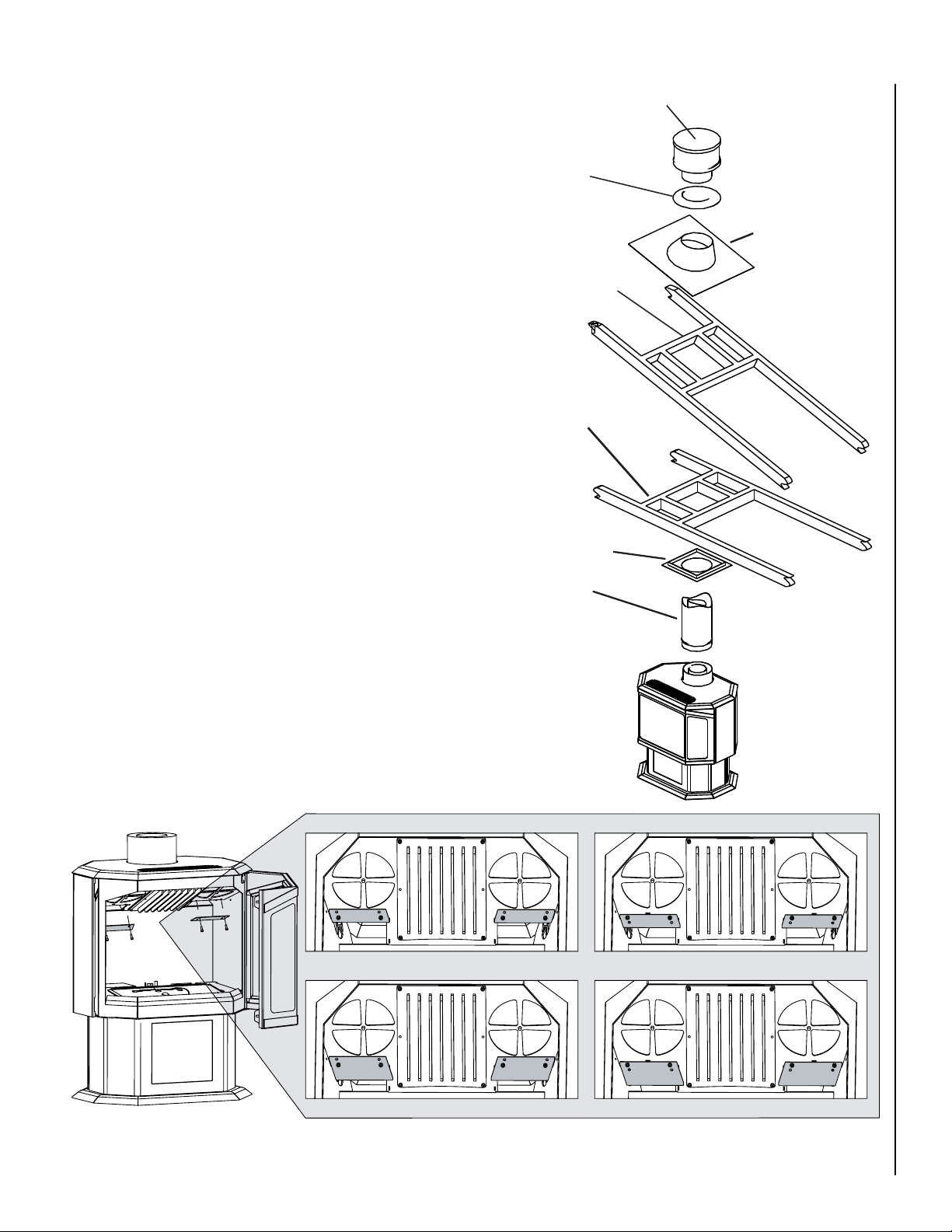
Page 7
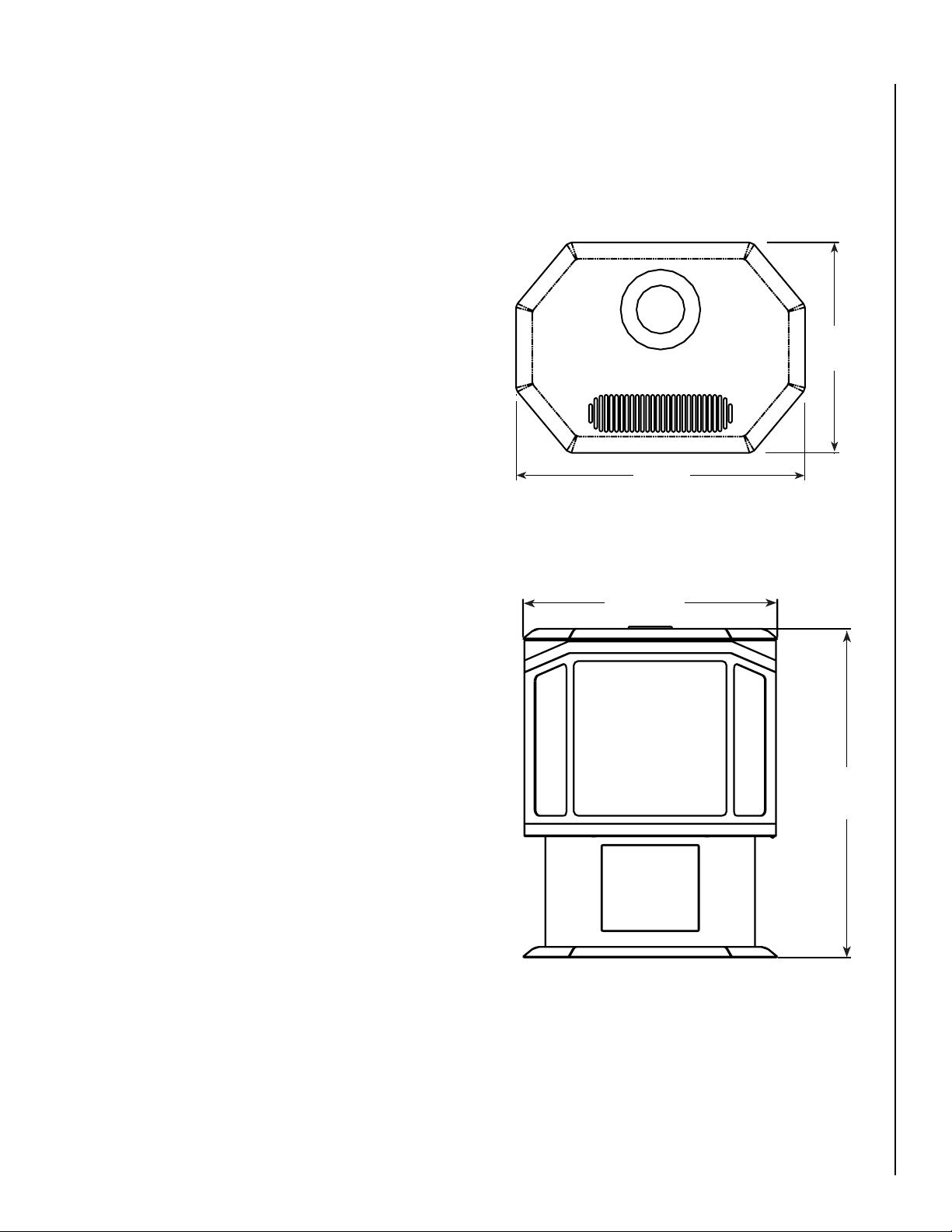
Preparing Your Epic™ Stove For Installation
23-1/2”
(597mm)
17”
(432mm)
23-1/2”
(597mm)
31-1/4”
(794mm)
Dimensions
Read all instructions before beginning your installation. If
instructions have not been read carefully, your installation
could void your warranty and may create a serious fire,
health, or other safety hazard.
The Lennox Hearth Products warranty will be voided if one
of the following occurs:
• Installation of any damaged stove or vent system
component.
• Unauthorized modification of the direct vent system.
• Installation other than as instructed by Lennox Hearth
Products, Security™ Chimneys, or Simpson DuraVent.
• Installation of any stove or vent system component not
manufactured or approved by Lennox Hearth Products,
Security™ Chimneys, or Simpson Dura-Vent.
When planning the installation for your Epic gas stove, it’s
necessary to consider the following:
• Where the unit is to be installed
• The vent system configuration to be used
• Gas supply (NG or LP)
• Electrical wiring
• Optional accessories (door trim assembly and wallmounted or remote thermostat)
The gas line attaches to the gas valve at the lower left corner
at the back of the stove. Test all gas connections for leaks
with a gas leak test solution.
Top View
Figure 1
Front View
Figure 2
NOTE: DIAGRAMS & ILLUSTRATIONS ARE NOT TO SCALE.
7
Page 8
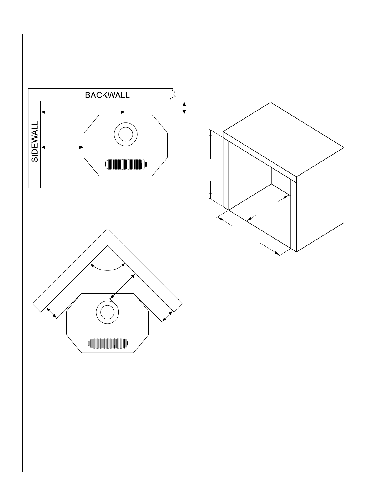
Clearances to Combustibles
Alcove dimensions
Minimum clearances to combustible materials in inches
(millimeters):
Parallel Installation
24-1/2”
(622mm)
Min.
12-1/2”
(318mm)
Min.
4” (102mm)
Figure 3
Corner Installation
The minimum width between the alcove side walls is 48”
(1219mm). The minimum height of the alcove is 69” (753mm)
and the maximum depth is 48” (1219mm).
Alcove Dimensions
69”
(753mm)
Min.
48”
(1219mm)
Max.
48”
(1219mm)
Min.
90°
10-1/2”
(267mm)
Min.
4-1/2”
(114mm)
Min.
4-1/2”
(114mm)
Min.
Figure 4
Floor Protection
A noncombustible hearth pad is not required. This stove
may be installed on a combustible surface. Also, the floor
beneath the stove must be stable, level, hard and strong
enough to support the stove without a tipping hazard.
Figure 5
Pipe Clearances
All installations using a vertical termination cap must
maintain one inch clearance between the direct vent pipe
and combustibles. For horizontal runs of pipe, one inch of
clearance to combustibles on the sides and bottom and two
inches on the top of the pipe is required. See Page 16 for
allowable pipe configurations.
8
NOTE: DIAGRAMS & ILLUSTRATIONS ARE NOT TO SCALE.
Page 9
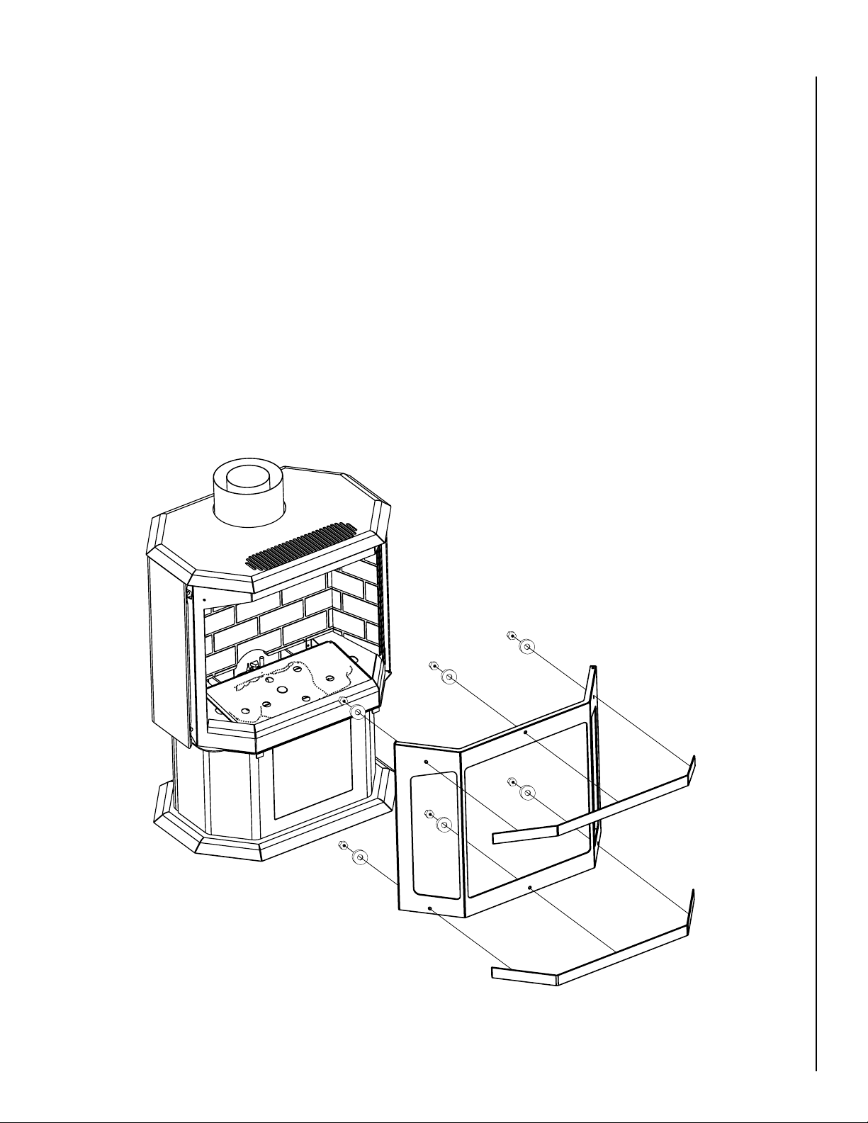
Installation
Trim Installation:
CAUTION: Always ensure that plated surfaces are clean
and free of fingerprints before lighting stove. Fingerprints
will leave permanent blemishes if left on plated surface
when lit. When installation is complete, the trim should
be gently cleaned with a soft cloth and either alcohol or
glass cleaner. Do not overtighten nuts, overtightening can
create visible dimples on the plated surface.
Packaging List: Trim pieces (2) - gold, brushed nickel,
black nickel, or black, #6 nuts (6), #6 washers (6)
Tools Required: 5/16” nut driver or socket wrench
1. Remove the trim pieces and hardware from its packaging
and ensure that all pieces are present before beginning
installation. Take care not to scratch finished surfaces.
2. Open right side door by removing socket head cap screw
located on the bottom of the side door near the front.
3. Open front door. Put trim in place by inserting trim studs
into the corresponding holes in the door. The top piece
of trim will only fit in one direction, but the bottom piece
can be installed incorrectly. When placing the bottom
piece of trim, make sure there is a small gap between the
bottom of the trim piece and the bottom of the door. If
the trim extends below the bottom of the door, the trim
is on upside down.
4. Place one washer on each stud. Using a 5/16” nut driver,
snug up the nuts on each piece of trim. Do not finish
tightening nuts.
5.There should be approximately a 1/8” gap between the
edge of the trim and the top and bottom edges of the door.
Visually inspect the alignment of the trim and adjust if
necessary.
6. Finish tightening nuts.
CAUTION - DO NOT OVERTIGHTEN
NUTS!!!
Figure 6
NOTE: DIAGRAMS & ILLUSTRATIONS ARE NOT TO SCALE.
9
Page 10
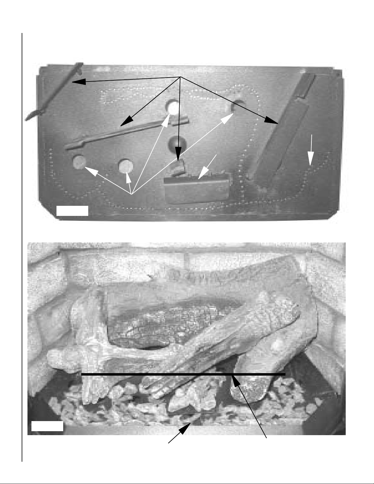
Firebox Setup
Figure 7
Burner Pan Diagram
Log Stands
1
2
3
Gas Ports
Air Deflector
4
Secondary Air Holes
Completed Firebox Setup
Figure 8
To ensure a proper burn leave a 1” space free of any
embers or rockwool directly in front of the air deflector
(see Burner Pan Diagram above).
10
Do not cover any secondary air holes or gas ports (see
Burner Pan Diagram above) behind this line.
NOTE: DIAGRAMS & ILLUSTRATIONS ARE NOT TO SCALE.
Page 11
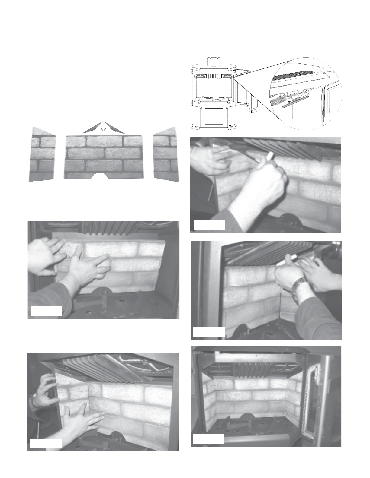
Brick Panel Installation
CAUTION: The brick panels are required for your appliance to function correctly and safely.
Packaging List: Rear brick panel (A), left brick panel (B), right
brick panel (C), retaining brackets (D) - in flue restrictor bag
1. Remove the brick panels from the box and carefully unwrap
them. The panels are fragile, so handle them with care.
Remove the bag containing the brick retaining brackets
(D) and flue restrictors from the firebox.
4. Using the included screws, install the brick retaining brackets
(D) above the left and right brick panels (B and C).
D
AB C
Figure 9
2. Install the rear brick panel (A) bottom first and stand it
flush against the rear of the firebox ensuring the pilot
cutout is at the bottom directly above the pilot.
Figure 12
Figure 13
Figure 10
3. Install the left panel (B) bottom first and stand flush against
left wall of firebox. Repeat for right panel (C) against the
right wall of firebox.
Figure 11
NOTE: DIAGRAMS & ILLUSTRATIONS ARE NOT TO SCALE.
Figure 14
Figure 15
11
Page 12

C
D
Log Set and Ember Installation
A
B
C
D
E
F
A
B
C
D
E
F
B
A
A
B
C
D
E
F
C
D
B
A
If logs are not installed according to the log installation
instructions, flame impingement and improper combustion
could occur and result in soot and/or excessive production of
carbon monoxide (CO), a colorless, odorless, toxic gas.
The size and position of the log set is critical to achieve
a safe, reliable and attractive flame pattern. Any attempt
to use a different log set in the fireplace will void the warranty and will result in incomplete combustion, sooting
and poor flame quality.
Figure 18
Packaging List: Log set [rear log (A), left rear log (B), left
front log (
1. Carefully remove the logs from their packaging and
Figure 16
2. Install left rear log (
C), center log (D)], embers (E) and rockwool (F)
ensure you have a complete set.
so handle them with care.
B) onto the front half of log stand
1 (see
Burner Pan Diagram, Page 10). When installed
correctly it should sit firmly in place with the charred
surface facing the center of the firebox.
The logs are fragile,
5. Place the rockwool (F) over the gas ports and in between
the embers along the front of the firebox. The rockwool
can be placed over gas ports but do not cover the secondary air holes (see Burner Pan Diagram, Page 10).
Figure 19
6. Place the left front log (
Pan Diagram, Page 10) and the center log (D) spanning
from log stand
rear log (
sit firmly in place with the charred side facing forward.
4 to the peg found on the right side of
A). When installed correctly, both logs should
C) on log stand 3 (see Burner
Figure 17
3. Place the rear log (
Pan Diagram, Page 10). The charred surface of the log
should face the front.
4. Place the embers (
embers first, create a small pile on the elevated air deflec
tor near the center and place
the burner (leaving about 1/4” in between each ember and
a 2” gap in the center). It will not affect the performance,
but smaller embers may
the rest of the embers throughout the firebox taking care
not to block off any secondary air holes or gas ports (see
12
example below for proper placement of embers).
Figure 20
A) onto log stands 1 and 2 (see Burner
E) on the burner pan. Using the larger
them along the front edge of
fall into the front air gap.
Place
NOTE: All logs are designed to fit only one way. For the
appliance to function properly, it is essential that the
-
logs be installed correctly. See below for an example of
a correctly burning Epic™ gas stove.
NOTE: DIAGRAMS & ILLUSTRATIONS ARE NOT TO SCALE.
Page 13

Minimum Components for Horizontal Installation:
C
D
Horizontal Termination Kit which includes:
• 1 6-5/8”x 6” Black Pipe
• 1 Riser Vent Terminal
• 1 Wall Penetration Heat Shield (Wall Thimble) (2 pcs)
• 1 Decorative Wall Trim (black)
• 1 Tube Mill-Pac
• Screws
Figure 21
Vent Installation
Venting:
The Epic™ gas stove has been tested and listed as a direct
vent heater system by OMNI-Test Laboratories, Beaverton, Oregon and is recommended for use with Security™
Secure Vent pipe*. Use only approved chimney brands
with this appliance.
Important:
• Read all instructions carefully before starting the instal
lation. Failure to follow these instructions may create a
fire or other safety hazard and will void the warranty.
Be sure to check for specific clearances to combustible
requirements on Page 8.
Do not extend the venting system vertically or horizontally in excess of the distance
prescribed on Page 16. Consult your local building codes
before beginning the installation.
• Always maintain the proper air spaces between the
vent pipe and nearby combustibles to prevent a fire
hazard. Do not fill air spaces with insulation. Be sure to
check the vent termination clearance requirements from
decks, windows, soffits, gas regulators, air supply inlets
and public walkways, as specified in these installation
instructions on Page 17 and local building codes.
• This gas stove and vent system must be vented directly
to the outside of the building and never be attached to
a chimney serving a separate solid fuel or gas-burning
appliance. Each direct vent gas appliance must use its
own separate vent system. Common vent systems are
prohibited.
• The Epic gas stove is recommended for use with Security™
Secure Vent pipe*. The appliances and vent manufactur
ers warranties will be voided and serious fire, health, or
other safety hazards may result from any of the following
actions:
• Installation of any damaged direct vent component.
• Unauthorized modification of the direct vent system.
• Installation of any vent component part not approved
or manufactured by the approved vent manufacturer.
• Installation other than as instructed by Lennox Hearth
Products and vent manufacturers instructions.
Residential and Mobile Home Installations:
These are the minimum pieces required. Other parts may
be required for your particular installation.
Optional Components:
• 45º Elbow
• Vinyl Siding Shield for Riser Vent Terminal
• Vent Guard
• Snorkel Termination (36”)
• Snorkel Termination (14”)
• Wall Penetration Heat Shield
Vent Considerations:
Twist-lock procedure: Four indentations on female ends of
pipes and fittings are designed to slide straight onto male
ends of adjacent pipes and fittings by orienting the four pipe
-
indentations so they match and slide into the four entry slots.
Push pipe sections completely together, then twist-lock one
section clockwise approximately one-quarter turn until the
two sections are fully locked. The female locking lugs will not
be visible from the outside on the pipe or fittings. They may
be located by examining the inside of the female ends.
Supports: Horizontal runs of vent must be supported every
3 feet. Wall straps are available for this purpose.
Pipe Sealing: If Simpson Dura-Vent pipe is used, the pipe
must be sealed as follows: seal both the inner and outer pipes
with a high temperature silicone sealant rated for at least
600ºF (commonly know as “RTV”). Run a 1/8” (3mm) bead
of silicone around outside of male end of outer sleeve. Run
a 1/8” (3mm) bead of silicone about 1/4” (6mm) from the
end of the male inner pipe, which is found in the pipe to be
attached above. Twist-lock the pipes or fittings together.
-
Sealant
Female Locking
Male
Locking
Lugs
Figure 22
* Other approved chimney brand is Simpson Dura-Vent DV-GS.
13
Page 14

Vent Parts List
Direct vent pipe Security™ Secure Vent™ * may be used
with the Epic™
the components available from each direct vent pipe manu
facturer. Snorkel terminations are available for applications
which may require vertical rise on the building exterior. The
components listed below come in a galvanized finish. Most
of the components are also available in a painted black fin
ish. Add a “B” to the end of the part number when ordering
if a black part is desired.
gas stove. Please see the lists below to verify
Horizontal Vent Installation
Venting terminals may not be recessed into a wall or
-
siding.
1. Set the unit in the desired location. Check whether or
-
not wall studs are in the way when the venting system is
attached. If wall studs are in the way, you may want to
adjust the location of the unit.
Security™ Secure Vent 6-5/8”x 4” Pipe
Part Number Description
SV4LC 6” Pipe Length
SV4L12 12” Pipe Length
SV4L24 24” Pipe Length
SV4L36 36” Pipe Length
SV4L48 48” Pipe Length
SV4LA 6” Pipe, Adjustable
SV4LA12 12” Pipe, Adjustable
SV4FA Flashing, 1/12 to 6/12 Roof Pitch
SV4FB Flashing, 7/12 to 12/12 Roof Pitch
SV4RSM Wall Radiation Shield
SV4E46 45º Elbow
SV4E90 90º Elbow
SV4VS Vinyl Shield Protector
SV4FC Storm Collar
SV4CGV Vertical Termination Cap
SV4BF Firestop
SV4CHC Horizontal Termination Cap
SV4STC36 Snorkel Termination Cap (36”)
SV4STC14 Snorkel Termination Cap (14”)
SV4BM Wall Band
Simpson Dura-Vent GS 6-5/8”x 4” Pipe
Part Number Description
908 6” Pipe Length
907 9” Pipe Length
906 12” Pipe Length
904 24” Pipe Length
903 36” Pipe Length
902 48” Pipe Length
911 11” to 14-5/8” Pipe, Adjustable
942 Wall Thimble
940 Rnd Support Box/Wall Thimble Cover
941 Cathedral Ceiling Support Box
943 Flashing, 0/12 to 6/12 Roof Pitch
943S Flashing, 7/12 to 12/12 Roof Pitch
945 45º Elbow
990 90º Elbow
950 Vinyl Siding Standoff
953 Storm Collar
963 Ceiling Firestop
988 Wall Strap
981 Snorkel Termination (36”)
982 Snorkel Termination (14”)
984 Horizontal Termination Cap
985 Horizontal Termination Cap (High Wind)
980 Vertical Termination Cap
991 Vertical Termination Cap (High Wind)
14
2. All horizontally terminated vent installations may only use
6-5/8”x 4” Security™ Secure Vent pipe*.
3. Assemble the desired combination of pipe and elbow(s)
to the appliance adapter with pipe seams facing down.
Offsetting the pipe seams as double seams in one place
will cause the outer pipe to take an oval shape.
4. When this pipe passes through a wall, a wall thimble
- Simpson #942 or Security™ #SV4RSM - is required.
The hole in the wall for the wall thimble should be 9-1/4”x
10-1/4”. If the wall being penetrated is constructed of noncombustible material (i.e. masonry block or concrete), a
7” diameter hole is acceptable and a wall thimble is not
required.
5. Horizontal runs of vent pipe must be supported every 3
feet. Wall straps - Simpson #988 or Security™ #SV4BM
- are available for this purpose.
6. If the vent passes through a ceiling or floor, a firestop
- Simpson #963 or Security™ #SV4BF - is required.
7. Also note that venting terminals shall not be recessed
into a wall or siding. If installing the termination cap on
a wall covered with vinyl siding, a vinyl siding standoff
- Simpson #950 or Security™ #SV4VS - or furring strips
must be used to ensure that the termination cap is not
recessed into the siding.
8. The horizontal run of vent should have a 1/4” (6mm)
rise for every 12” of run toward the termination. Never
allow the vent to run downward. This could cause high
temperatures and may present the possibility of a fire.
9. The location of the horizontal vent termination on an ex
terior wall must meet all local and national building codes
and must not be blocked or obstructed. For allowable
external vent termination locations see Page 17
.
10. Allowable clearances from the vent pipe to combustible
materials must be maintained. See Page 8 for these clear
ances.
11. Do not locate the termination cap where it may be blocked
by shrubbery or snow.
* Other approved chimney brand is Simpson Dura-Vent DV-GS.
-
-
Page 15
Vertical Vent Installation
Storm Collar
Vertical Termination Cap
Ceiling Firestop
Ceiling Minimum
Framing 10”x 10”
Roof - Maintain
1” Clearance
to Combustibles
Pipe Length
Flashing
Important Notes
1. All vertically terminated vent installations use 6-5/8”x 4”
Security™ Secure Vent™ pipe*.
2. If the vent passes through a ceiling or floor, a firestop
- Simpson #963 or Security™ #SV4BF - is required.
3. If the vent passes through the roof, a roof flashing - Simp
son #943 or 943S or Security™ #SV4FA or SV4FB - and
storm collar - Simpson #953 or Security™ #SV4FC - are
required.
4. A 1-inch clearance from the vent pipe to combustible
materials must be maintained.
5. A maximum of either two 45º elbows or two 90º elbows
may be used. See Page 16 for allowable offsets.
6. The maximum system height is 30 feet (9.1M) and the
minimum is 10 feet (3M).
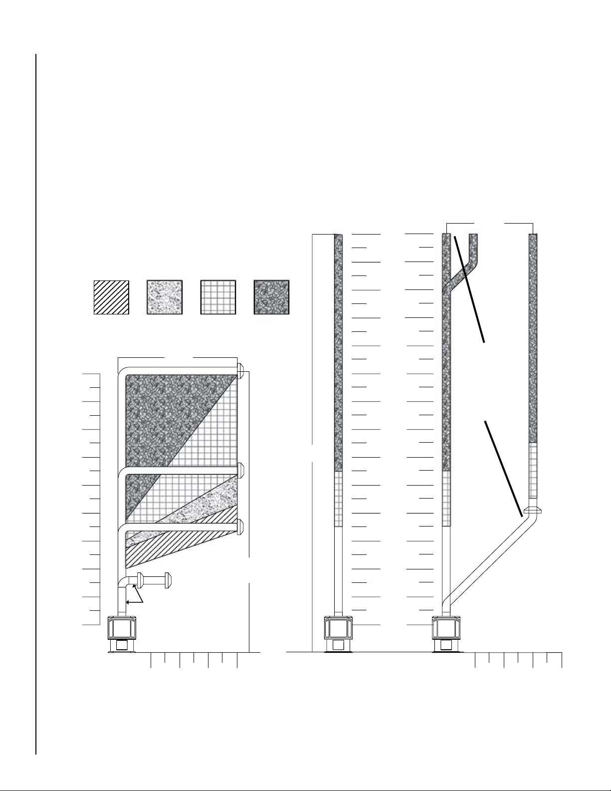
Flue Restrictors
This stove requires a balanced flue to ensure proper combustion. As such, flue restrictors may need to be installed
depending on the vent configuration of your stove. The
drawings on the next page show all the allowable pipe con
figurations for the Epic™ gas stove. To properly install the
flue restrictors, find your pipe configuration in the drawings
on the next page and note which restrictor setting is recom
mended. The flue restrictors are shipped in the firebox of
your stove. Install the flue restrictors using the four allen
head screws according to the diagram below. Install the
flue restrictor screws in their original holes in the top of
the firebox. Restrictor positions are based on tests run in
a laboratory.
-
-
-
Figure 23
* Other approved chimney brand is Simpson Dura-Vent DV-GS.
Figure 24
A
C
NOTE: DIAGRAMS & ILLUSTRATIONS ARE NOT TO SCALE.
B
D
15
Page 16
2
4
6
8
10
12
14
16
18
20
2
4
6
8
10
12
14
16
18
20
22
24
26
28
MIN. 24" VERT. PIPE SECT.
WITH 9" HORIZONTAL SECT.
8' MAX
30' MAX
30
19' 7" MAX VERT. WITH
8' HORIZONTAL
VERTICAL HEIGHT (FT)
2 4 6 8
2 4 6 8
VERTICAL HEIGHT (FT)
HORIZONTAL DISTANCE (FT)
HORIZONTAL DISTANCE (FT)
6' MAX
Horizontal Terminations
Vertical Terminations
The shaded areas in the diagram below show all allowable
combinations of vent configurations with horizontal termi
nations. Horizontal sections of pipe require 1/4” of rise for
every 12” of run. A second 90° or 45° elbow (in addition to
the first 90° elbow at the top of the vertical length of pipe)
is allowed as long as the overall length of the horizontal
run of pipe does not exceed those shown below. Use the
restrictor positions indicated. Note that if the termination
cap falls in the unshaded area, then no restrictor is installed
in the stove.
RESTRICTOR POSITIONS
A B C D
The diagram below shows all allowable combinations of
-
straight vertical and offset to vertical vent configurations
with vertical terminations. The termination must fall within
the shaded areas on the diagram. Use the restrictor positions
indicated. Offsets may consist of two 90° elbows OR four
45° elbows. The minimum termination height is 10 feet and
the maximum is 30 feet.
NOTE: Horizontal pipe requires 1/4” rise for every 12”
of run. Offsets must remain within max and min lines.
Vertical height is measured from the bottom of stove.
2’ (MIN) OF
VERTICAL PIPE
REQUIRED
BELOW
TERMINATION
Figure 25
Figure 26
16
NOTE: DIAGRAMS & ILLUSTRATIONS ARE NOT TO SCALE.
Page 17
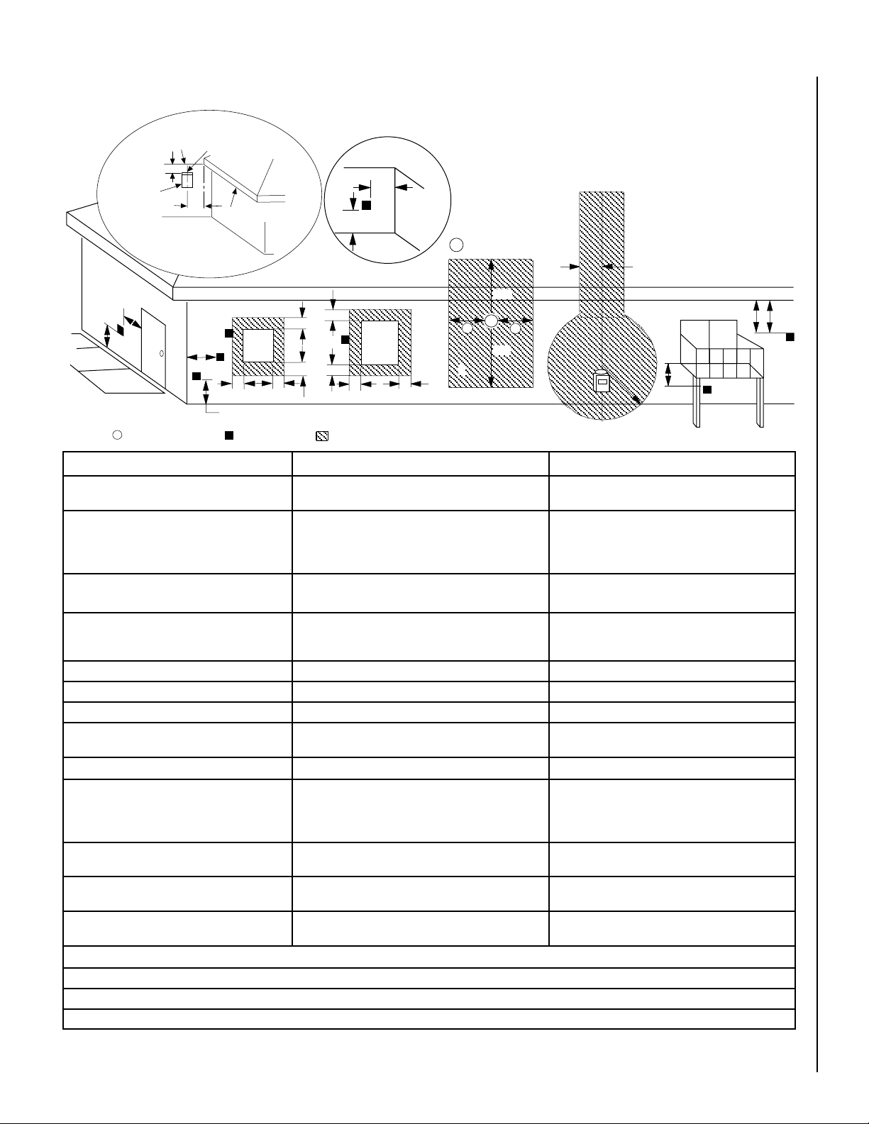
Exterior Horizontal Vent Termination Clearance Requirements
V
V
V
V
V
F
C
B
B
A
B
H
M
I
X
V
D
V
A
A
A
V
L
B
J
X
E
V
A
G
*18”
18”
B
C
C
C
* See Item D in the Text Below.
Exterior Wall
Horizontal
Termination
Inside Corner
= Air Supply Inlet
Center Line
of Termination
DETAIL D
Ventilated Soffit
Fixed
Closed
Window
= Vent Terminal
Inside
Corner Detail
= 9" in U.S.
= 12" in Canada
Operable
Window
= Area where Terminal is NOT permitted
3 ft.
3 ft.
Minimum Clearances Canadian Installation * US Installation **
A = Clearance above grade, veranda, porch, deck
or balcony.
B = Clearance to window or door that may be
opened.
C = Clearance to permanently closed window 12 inches (305 mm) recommended to prevent window
12 inches (30 cm) * 12 inches (30 cm) **
6 in. (15.2 cm) for appliances < 10,000 BTU/hr (3kW),
12 in. (30 cm) for appliances > 10,000 BTU/hr (3kW) and <
100,000 BTU/hr (30kW), 36 inches (91 cm) for appliances
> 100,000 BTU/hr (30kW)*
condensation
6 in. (15.2 cm) for appliances < 10,000 BTU/hr (3kW),
9 in. (23 cm) for appliances > 10,000 BTU/hr (3kW) and <
50,000 BTU/hr (15kW), 12 inches (30 cm) for appliances
> 50,000 BTU/hr (15kW)*
9 inches (229 mm) recommended to prevent window
condensation
D = Vertical clearance to ventilated soffit located
18 inches (458 mm) 18 inches (458 mm)
above the terminal within a horizontal distance of 18
in. (458 mm) from the center line of the terminal
E = Clearance to unventilated soffit 12 inches (30 cm) 12 inches (30 cm)
F = Clearance to outside corner 5 inches (12.7 cm) 5 inches (12.7 cm)
G = Clearance to inside corner 6 in. (15 cm) 6 in. (15 cm)
H = Clearance to each inside of center line extended
above meter / regulator assembly
3 feet (91 cm) within a height of 15 feet above the meter /
regulator assembly *
3 feet (91 cm) within a height of 15 feet above the meter
/ regulator assembly **
I = Clearance to service regulator vent outlet 3 feet (91 cm) * 3 feet (91 cm) **
J = Clearance to non-mechanical air supply inlet
to building or the combustion air inlet to any other
appliance
K = Clearance to mechanical air supply inlet 6 feet (1.8 meters) * 3 feet (91 cm) above, if within 10 feet (3 m) horizon
L = Clearance above paved sidewalk or paved
driveway located on public property
M = Clearance under veranda, porch, deck or
balcony
* In accordance with the current CSA-B149.1 National Gas and B149.2 Propane Installation Code - Latest Editions.
6 in. (15.2 cm) for appliances < 10,000 BTU/hr (3kW), 12
in. (30 cm) for appliances > 10,000 BTU/hr (3kW) and <
100,000 BTU/hr (30kW), 36 inches (91 cm) for appliances
> 100,000 BTU/hr (30kW)*
7 feet (2.13 m) ‡ 7 feet (2.13 m) ‡
6 in. (15.2 cm) for appliances < 10,000 BTU/hr (3kW), 9
in. (23 cm) for appliances > 10,000 BTU/hr (3kW) and <
50,000 BTU/hr (15kW), 12 inches (30 cm) for appliances
> 50,000 BTU/hr (15kW)*
tally**
12 in. (30 cm) * ‡ 12 in. (30 cm) ** ‡
** In accordance with the current ANSI Z223.1 / NFPA 54 National Fuel Codes - Latest Edition.
‡ A vent shall not terminate directly above a sidewalk or paved driveway which is located between two single family dwellings and serves both dwellings.
*‡ Only permitted if veranda, porch, deck or balcony is fully open on a minimum 2 sides beneath the floor.
Figure 27
NOTE: DIAGRAMS & ILLUSTRATIONS ARE NOT TO SCALE.
-
17
Page 18
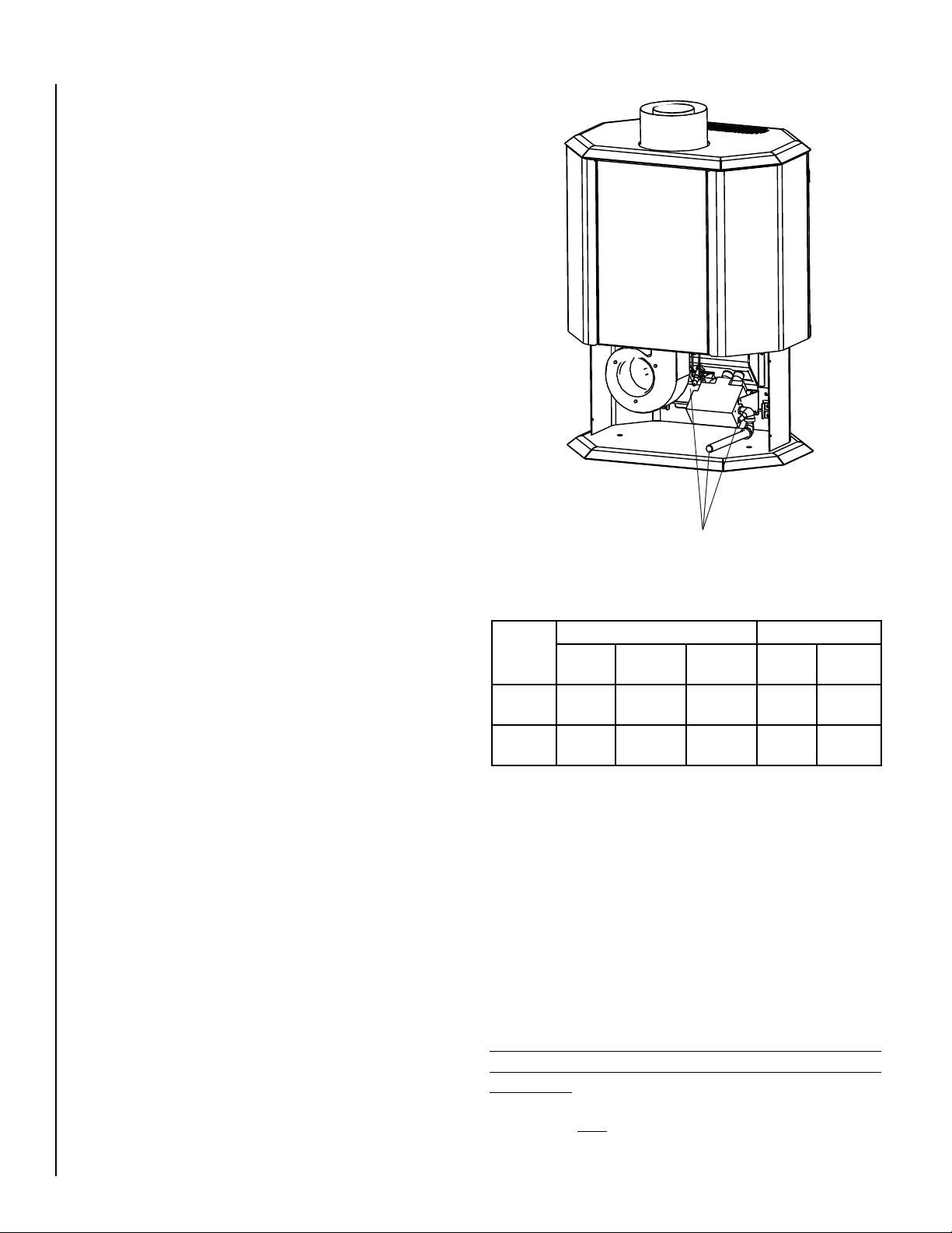
Gas Line Installation
Check all connections
for leaks using a gas
leak test solution.
This stove must be connected to the gas line in accordance
with local codes and/or the National Fuel Gas Code, ANSI
Z223.1 (In Canada, the current CAN/CSA B149.1 installa
tion code). Remove the four screws holding the back of
the pedestal in place. Slide rear cover back far enough to
gain access to the inside of the pedestal. Remove plastic
plug from the 3/8”x 9” pipe. Connect gas line to the 3/8”x 9”
pipe. After connecting the gas line, all joints in the line and
connections at the valve should be checked for leaks before
final positioning of the unit. Conduct a gas leakage test of
the appliance piping and control system downstream of the
shutoff valve in the supply line to the appliance.
Gas Pressure Requirements
A MAJOR CAUSE OF OPERATING PROBLEMS WITH GAS
APPLIANCES IS IMPROPER GAS PRESSURE!
The most important item to check during the initial
installation and the first thing to check when operating
problems occur is gas pressure! This appliance will
not function properly unless the required gas pressure
is supplied. See the table on this page for gas pressure
requirements.
Two pressure taps are provided on the stove’s valve to
check gas pressures. To access the taps, remove the four
socket head screws from the valve control panel. The taps
are located below the On/Off/Pilot knob (see Figure 20 on
Page 20
To check inlet pressure (with the stove burning) insert a
small flat-bladed screwdriver into the tap and turn a halfturn counterclockwise. Cover the tap with the line from the
manometer and check the pressure. Close the tap gently
but securely after completing the check. The manifold
(outlet) tap is to the right of the inlet tap. To check manifold
pressure (with the stove burning at the high burn setting)
insert a small flat-bladed screwdriver into the tap and turn a
half-turn counterclockwise. Cover the tap with the line from
the manometer and check the pressure. Again close the tap
gently but securely after completing the check. Check the
taps for gas leaks with a gas leak test solution (retighten if
necessary).
If the pressure is not sufficient, make sure the gas supply
line is large enough, the supply regulator is properly adjusted
and the total gas load for the residence does not exceed the
amount supplied.
The appliance and its individual shut off valve must be
disconnected from the gas supply piping system during
any pressure testing of that system at test pressures in
excess of 1/2 psig.
The appliance must be isolated from the gas supply piping
system by closing its individual manual shut-off valve
during any pressure testing of the gas supply piping system
at test pressures equal to or less than 1/2 psig. Check
with your gas supplier or plumber.
). The left tap is the inlet (supply) pressure side.
-
Figure 28
Fuel
Type
Natural
Gas
LP Gas 11" WC 11" WC 13" WC 10" WC 6.0” WC
Desired Minimum Maximum On Hi
7" WC 5" WC 10.5" WC 3.5" WC 1.7" WC
Inlet Pressure Manifold Pressure
Fire
LP and Natural Gas Supplies:
Your Epic™ gas stove is equipped from the factory for use
with natural gas only as specified on the Safety / Listing
label attached to the appliance. This appliance can only be
operated using propane gas (LP) if a certified fuel conversion kit provided by Lennox Hearth Products is installed by
a qualified service technician.
Also check the orifice size on the label on the igniter bracket.
It must be the correct size for the fuel and altitude.
Do not run propane tank dry. Running the tank dry may
cause a hazardous condition due to pressure drop in
empty tank.
Solid fuel is NOT to be used with this unit.
On Lo
Fire
18
NOTE: DIAGRAMS & ILLUSTRATIONS ARE NOT TO SCALE.
Page 19
Operating Instructions
WHAT TO DO IF YOU SMELL GAS:
Pre-Lighting Checklist:
Be sure to check these items before the initial lighting of
the stove:
c The stove gas label corresponds to the gas supply
available - that is “natural gas” for natural gas or “LP
gas” for LP gas.
c Gas pressure has been checked carefully - see Page
18.
c All gas fittings have been checked for leaks.
c All clearances to combustibles have been met - see
Page 8
c All combustible materials have been removed from
area in front of the stove.
c All vented areas of the stove are unobstructed.
c House is ventilated to clear initial paint curing odors
- see Page 21
c All packaging materials have been removed from the
firebox.
c While stove is cool, fingerprints or other marks have
been cleaned from any gold or nickel surfaces with
denatured alcohol and a soft cloth. Marks left on these
surfaces may become etched into the finish if not
removed prior to burning the unit.
c Brick panel, log set and embers have been installed.
c The glass door is in place and is properly sealed.
.
.
DO NOT try to light the appliance. DO NOT touch any electric
switch. DO NOT use any phone in the building. Immediately
call your gas supplier from a neighbor’s phone. Follow the gas
supplier’s instructions. If you cannot reach your gas supplier, call
the fire department.
C. Use only your hand to push in or turn the gas control knob.
Never use any tool. If the knob will not push in or turn by hand,
don’t try to repair it, call a qualified service technician. Force
or attempted repair may result in a fire or explosion.
D. DO NOT use this appliance if any part has been under water.
Immediately call a qualified service technician to inspect the
appliance and to replace any part of the control system and
any gas control which has been under water.
OPERATING INSTRUCTIONS
CAUTION: YOUR LENNOX™ GAS APPLIANCE MUST ALWAYS
BE OPERATED WITH THE GLASS DOOR IN PLACE.
STOP!! Read the safety information above before proceeding.
1. Make sure gas supply shut off cocks are open and ON/OFF
rocker switch is “OFF.” If equipped with a thermostat, set it to
the lowest setting.
2. Turn off all electrical power to the appliance.
3. Push in gas cock dial slightly and turn clockwise to
“OFF”.
Lighting Instructions:
The following is a copy of the operating and lighting instructions
found with each stove:
FOR YOUR SAFETY READ BEFORE OPERATING
WARNING: IF YOU DO NOT FOLLOW THESE INSTRUCTIONS
EXACTLY, A FIRE OR EXPLOSION MAY RESULT CAUSING PROPERTY DAMAGE, INJURY, OR LOSS OF LIFE.
CAUTION: HOT WHILE IN OPERATION. DO NOT TOUCH. KEEP
CHILDREN, FURNITURE, GASOLINE AND OTHER LIQUIDS WITH
FLAMMABLE VAPORS AWAY. NEVER OPERATE UNIT WITH GLASS
DOOR OFF OR ATTEMPT TO OPEN THE DOOR WHILE HOT.
A. This appliance is equipped with a piezo ignition device to light
the pilot. When lighting the pilot, follow these instructions
exactly.
B. BEFORE LIGHTING, smell around the appliance area for gas.
Be sure to smell next to the floor, because some gas is heavier
than air and will settle on the floor.
NOTE: Dial cannot be turned from “PILOT” to “OFF” unless dial
is pushed in slightly. Do not force.
4. Wait five minutes to clear out any gas. If you smell gas, STOP!!
Follow “B” above. If you don’t smell gas, continue.
5. Locate the pilot by looking through the hole under the right front
log. Blue flame will be seen when the pilot is lit.
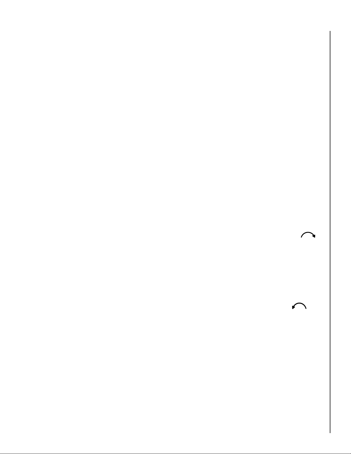
6. Turn the gas control knob counter-clockwise to the
“PILOT” position.
7. Push the knob all the way in and hold in that position. Immediately light the pilot by pressing the igniter button several
times until pilot is lit. Continue to hold the knob in for about
30 seconds after the pilot is lit. Release knob and it will pop
back out. Pilot should remain lit. If it goes out, repeat steps
4-8 holding knob in an additional 15 seconds after pilot is lit.
If knob does not pop out when released, stop and immediately
call your service technician or gas supplier. If the pilot will not
stay lit after several tries, turn the gas control knob to “OFF”
and call you service technician or your gas supplier.
19
Page 20
8. After pilot is lit, turn gas control counter-clockwise to
ON
OFF
PILOT
HI
LOW
GAS CONTROL
ON/OFF
FLAME HEIGHT
“ON.” Knob can only be turned “ON” if the knob has popped
out.
9. To turn burner on, turn “ON/OFF” rocker switch to “ON” or
set the thermostat to the desired temperature above room
temperature.
10. Adjust the flame height (and heat output) by turning the flame
height knob clockwise for reduced flame and counterclockwise for full flame.
11. Set the blower to the desired air flow after it turns on when the
appliance reaches operating temperature.
TO TURN OFF GAS TO APPLIANCE
1. Turn the “ON/OFF” rocker switch and/or thermostat (if installed)
to “OFF.”
2. Turn off electric power to the appliance if service is to be
performed.
3. Turn gas control knob clockwise to “OFF.” Do not
force.
This appliance needs fresh air for safe operation and must be
installed so there are provisions for adequate combustion and
ventilation air. See Installation and Operation Manual accompanying appliance.
SHUTDOWN PROCEDURE
To turn off the burner, turn the rocker switch to “OFF” or adjust
the thermostat (if installed) to a setting below room temperature.
The pilot will remain lit for future burner ignition. For complete
shutdown, see “TO TURN OFF GAS TO APPLIANCE” above.
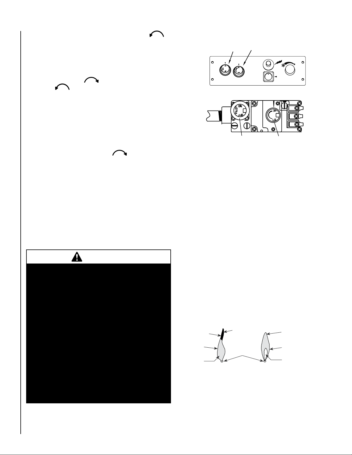
Control Panel
SIT Millivolt Gas Valve
Flame Height Control
Knob (HI/LO)
Figure 29
Gas Control Knob
(Pilot / On / Off)
Flame Color and Behavior
Your stove is designed for maximum heating efficiency.
Therefore, upon lighting of the main burner the flames will
be semitransparent or “bluish.” After 10-20 minutes of
operation, the logs will heat up and the flames will become
a yellow/orange color.
Adjusting the stove to cause the flames to turn orange sooner
may result in poor combustion, sooting and a hazardous
situation. See the drawing to the right showing proper flame
appearance.
• Improper installation, adjustment, alteration,
• Operation of this appliance when not connected
• Carbon monoxide poisoning – early signs of
WARNINGS
service or maintenance can cause injury or
property damage. For assistance or additional
information, consult a qualified installer, service
agency or your gas supplier.
to a properly installed and maintained venting
system can result in carbon monoxide (CO)
poisoning and possible death.
carbon monoxide poisoning resemble the flu
with headaches, dizziness, or nausea. If you
have these signs, get fresh air at once! Have
the heater inspected by a qualified service
technician. Some people are more affected by
carbon monoxide than others. These include
pregnant women, people with heart or lung
disease or anemia, those under the influence
of alcohol and those at high altitudes.
When testing for proper operation - If an optional thermo
stat is installed adjust it to its highest temperature setting.
Visually determine that main burner gas is burning properly:
i.e., no floating, lifting or flashback. Adjust the primary air
shutter(s) as required. Check for proper main burner opera
tion at both high and low flame.
Burner Flame Appearance
Soot at
Flame Tip
Dark Orange
Flame
No Blue Flame
Center
IMPROPERLY
BURNING FLAME
Soot above
Flame Tip
Ports on Pan
Burner Assembly
PROPERLY
BURNING FLAME
No Soot at
Flame Tip
Semi-Transparent
Yellow Flame
Blue Flame
Center
Figure 30
-
-
20
NOTE: DIAGRAMS & ILLUSTRATIONS ARE NOT TO SCALE.
Page 21
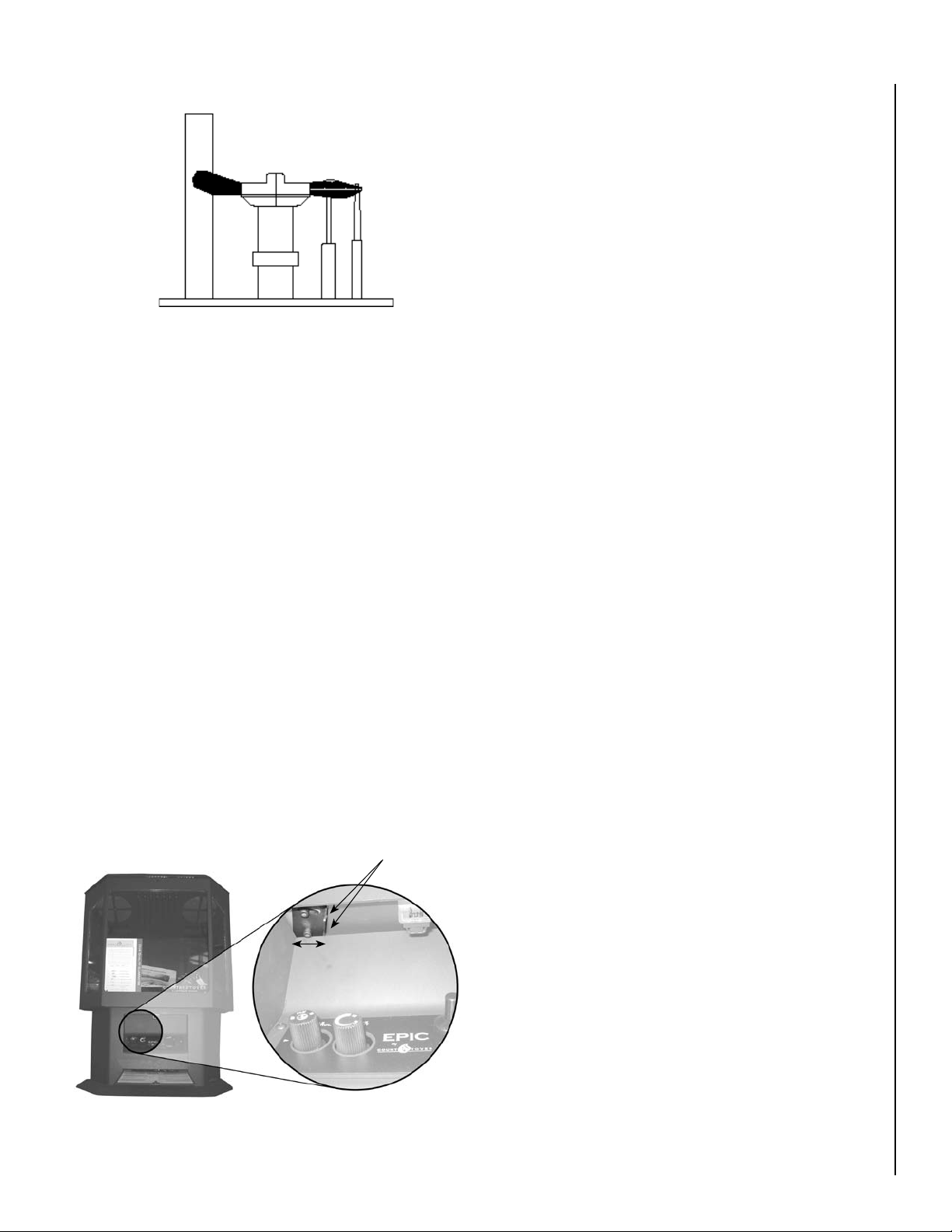
Figure 31
Pilot Flame Appearance
Quiet Operation
As the Epic gas stove is burning, a number of normal operational sounds may be heard. The flow of gas through the
gas valve and orifice may make a rushing or whistling noise.
If this noise is objectionable, it can be reduced by turning
down the flame. Turning down the flame can reduce total
heat output by more than 30%. When the blower turns on,
the sound of rushing air may be heard. The blower sounds
may be reduced by adjusting the speed control located on the
blower assembly. Also, a slight clicking sound may be heard
as the gas valve or blower switch is turned on and off.
Air Shutter Adjustment
CAUTION: Air shutter is hot while the Epic™ gas stove
is operating and should only be adjusted using a heat
resistant glove.
The air shutter control lever is located inside the main
control door above the control panel. The lever is linked to
the primary air shutter on the main burner. The air shutter
regulates the amount of primary air the burner receives
and, therefore, how clean the stove burns. The air shut
ter should only be adjusted by a qualified gas technician.
The stove should burn for about 15 minutes with the logs
installed before adjusting the air shutter. Moving the lever
to the left (closing the shutter) will raise the height of the
flames as well as turn them more yellow/orange. Moving
the lever to the right will open the shutter, turning the flames
to a cleaner transparent blue and enhance the glow of the
logs.
CAUTION: The air shutter should never be set so as
to make the tips of the flames sooty or create sooting on
the viewing glass, logs, or firebox ceiling. If soot begins
to form after burning, the air shutter should be opened
gradually until the sooting condition stops. Gas quality
and gas pressure may vary, which can affect the burning
characteristics of the stove.
Paint Curing
This stove has been painted with Stove Bright high temperature metallic paint. It leaves the factory dry to the touch, but
completes the curing process as the stove is used. To cure
the paint, burn the appliance four successive times for ten
minutes each time with a five minute cool down between
each firing. Also some parts of the appliance may be lightly
coated with machining oil. Ventilate the house during these
first firings as the paint and oil give off carbon dioxide and
unpleasant odors. It is recommended that persons sensi
tive to an imbalance in the indoor air quality avoid the stove
during the curing process.
Optional Wall Thermostat
If an optional wall thermostat is to be installed, install the
thermostat per the manufacturers instructions (provided with
the thermostat). Failure to follow manufacturers instructions
could result in a malfunction. Pay special attention to the
thermostat location requirements. If the location require
ments are not adhered to the appliance, erratic operation
or failure may occur.
Do not mount the thermostat where it may be affected by:
-
-
Air Shutter Adjustment Handle, highlighted
Figure 32
Loosen screws to adjust, tighten
screws when adjustment is complete.
Closed Open
NOTE: DIAGRAMS & ILLUSTRATIONS ARE NOT TO SCALE.
• Radiant heat from this appliance, fireplaces, sun or other
heat sources.
• Drafts or dead spots behind doors or in corners.
• Hot or cold air from ducts.
21
Page 22

Operating Options
Your stove comes equipped with an “On/Off” rocker switch
used to turn the burner on and off while the pilot light is
on. The switch is a round rocker switch located behind the
main control panel door.
A millivolt wall thermostat, or a remote control, can be used
to supplement the rocker switch. The gas valve is powered
by millivolts generated by the pilot assembly. This millivolt
system is very sensitive to electrical resistance, therefore,
make sure all connections are tight, clean and free from
corrosion. Do not splice any millivolt wires. Consult the
table below to determine the proper gage of wire for the
thermostat or wall switch connections. This table refers
to the total length of the wire (out to the switch and back).
The thermostat must be a millivolt type. A 24-volt furnace
thermostat will not work. Never hook up household current
- 120 Volts - to the millivolt system. It is not recommended
to hook up any more than two switches to the stove (for
example a rocker switch and a wall thermostat). Additional
switches may affect the system resistance and increase the
chance of the burner not igniting.
Follow the instructions included with the thermostat or
remote control for wiring. The thermostat, remote control
and rocker switch will turn the burner on and off indepen
dently. Be sure to set the rocker switch to the “Off” position
when using the thermostat or remote control and set the
thermostat or remote control to the lowest temperature when
you wish to use the rocker switch only, otherwise one may
override the other.
Millivolt Control System
This stove operates on a millivolt control system. As such,
no additional power supply is needed for the stove to heat.
The pilot assembly contains a thermocouple that, when
heated by the pilot flame, generates electricity (millivoltsmV=1/1000 of a volt) which opens a valve allowing gas to
continue flowing to the pilot assembly. The pilot assembly
also contains a thermopile that, when heated by the pilot
flame, generates electricity that flows to terminal #1 (labeled
TPTH) on the gas valve. When the electricity is conducted
from terminal #1 through the on/off switch, thermostat, or
receiver of the remote control to terminal #3 (labeled TH)
on the gas valve, the main burner will ignite.
-
Millivolt Control Schematic
Sparker
Piezo Igniter
Thermocouple
Pressure Taps
Gas Inlet
CAUTION: Label all wires prior to disconnection when
servicing controls. Wiring errors can cause improper
and dangerous operation. Verify proper operation after
servicing.
Figure 33
Pilot Hood
Pilot Assembly
Pilot Gas Line
Gas Valve
Wiring Terminals
Thermopile
Terminal 2
ON/OFF Rocker Switch,
Thermostat, or Remote
Thermostat
Thermostat Wire
Wire Size Maximum Length
12 Gage 100 Feet
14 Gage
16 Gage
18 Gage 25 Feet
20 Gage 16 Feet
Terminal 3Terminal 1
64 Feet
40 Feet
22
NOTE: DIAGRAMS & ILLUSTRATIONS ARE NOT TO SCALE.
Page 23
Maintenance and Servicing
2. The viewing glass should be cleaned periodically (see
Glass Door Cleaning and Maintenance).
Maintenance Checklist:
The following should only be performed by a qualified
service technician.
CAUTION: Label all wires prior to disconnection when
servicing controls. Wiring errors can cause improper
and dangerous operation. Verify proper operation after
servicing.
1. Annual inspection should be made and the following
checks performed:
oWhen unit is cool, open glass viewing door and inspect
burner for dirt, soot and lint accumulations and remove
if necessary. If excessive soot accumulation is present
on burner, have a qualified service technician adjust
burner for proper combustion.
oClean inside of glass viewing door with gas fireplace
glass cleaner. NEVER attempt to open door or clean
glass when unit is hot.
oCheck the hot air outlet vents for lint or other accumula-
tions. Never block or restrict vent openings or obstruct
flow of ventilation air.
oCheck that direct vent pipe, air intake and flue are open
and free of soot, blockage, or debris.
oCheck gaskets once a year. Gaskets must be tight. Replace
if necessary.
oInspect the pilot system for proper flame. NEVER ADJUST
THE PILOT until after the gas pressure has been checked
and supply lines have been completely bled (this may
take an hour or more when bleeding through the pilot).
All pilots are checked and burned at the factory prior to
shipment. The pilot adjustment screw is located to the
lower left of the flame height control knob.
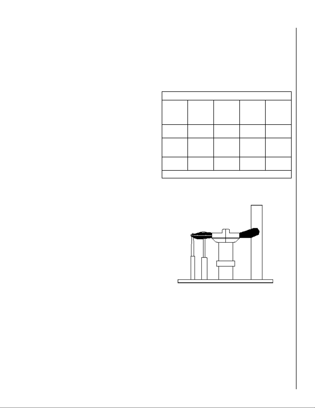
.2 Adjust the pilot screw to properly size the flames. The
flames should completely surround the thermopile
and thermocouple and extend across the main burner
tube ports. Be careful not to back the screw out of its
threads.
oCheck that the area around the stove is kept clear and
is free of combustible materials, gasoline and other
flammable vapors and liquids.
oCheck the millivolt system as per the table on this
page.
3. Should repairs or maintenance of the stove require
the disassembly of the vent/air intake system, the
reassembly and resealing should be completed by a
qualified service technician and follow the instructions
on Page 13 of this manual.
Millivolt and System Checks
Check
Test
A Complete
B Thermopile
C System
To
Test
System
Output
Resistance
See Figure 33 - Wiring Terminals
Connect
Meter
Leads to
Terminals
2 & 3 Closed 100 MV
1 & 2 Open Greater
2 & 3 Closed 2.5 Ohms
Thermostat
Connects
Meter
Reading
Should Be
or More
Than
325 MV
ProPer Pilot Flame aPPearance
Figure 34
NOTE: DIAGRAMS & ILLUSTRATIONS ARE NOT TO SCALE.
23
Page 24

Vent Pipe Maintenance
Glass Door Cleaning and Maintenance
Conduct an inspection of the venting system semiannually.
Recommended areas to inspect are as follows:
1. Check areas of the venting system which are exposed to
the elements for corrosion. These will appear as rust spots,
streaks, or, in extreme cases, holes. These components
should immediately be replaced.
2. Remove the cap and shine a flashlight down the vent.
Remove any bird nests or other foreign material.
3. Check for evidence of excessive condensate, such as
water droplets forming in the inner liner and subsequently
dripping out at joints. Continuous condensate can cause
corrosion of caps, pipe and fittings. It may be caused by
having excessive lateral runs, too many elbows, or exterior
portions of the system being exposed to cold weather.
4. Inspect joints to verify that no pipe sections or fittings have
been disturbed and consequently loosened. Also check
mechanical supports such as wall straps or plumbers’
tape for rigidity.
Cleaning: When cool, the glass may be cleaned with a clean,
soft cloth and glass cleaner. For cleaning white condensation
from the interior glass use KEL KEM gas stove glass cleaner
available from your stove dealer. Use of caustic or abrasive
cleaners may damage glass. Gold or nickel plated trim must
be cleaned with glass cleaner or denatured alcohol and a
soft cloth before firing or fingerprints and stains will remain
permanently. Never use abrasive polish to clean the gold or
nickel as it will ruin the finish. DO NOT operate stove with
broken glass. DO NOT clean door or glass when hot. DO
NOT abuse glass door by striking or slamming shut. DO NOT
use substitute materials if replacing glass. DO NOT spray
commercial glass cleaner with ammonia on the door and
glass gasket as it may dissolve the gasket glue.
WARNING: Do not operate appliance with the glass panel
removed, cracked, or broken. Do not remove glass door
while the stove is hot. Replacement of the glass door
should be done by a qualified service technician.
Glass Replacement: If the glass in your door is damaged
or broken, the complete door assembly (including gaskets)
must be replaced using part number H3102. The replace
ment door assembly is available from your Lennox Hearth
Products dealer. The glass is neo-ceramic and alternative
types must not be used. See Page 25 for door assembly
replacement instructions.
-
WARNING: Do not operate appliance with the glass panel
removed, cracked, or broken. Do not remove glass door
while the stove is hot. Replacement of the glass door
should be done by a qualified service technician.
24
NOTE: DIAGRAMS & ILLUSTRATIONS ARE NOT TO SCALE.
Page 25

Opening and Removing Door
If the glass in your door is damaged or broken - the complete door assembly must be replaced using part #45715.
CAUTION: Do not attempt to open the main door while
the unit is burning or still hot. Let the unit cool before
opening the door.
To replace the door:
1. Shut off the main burner using the rocker switch.
2. Shut off the pilot flame by turning the pilot knob clock
wise to “OFF.”
3. Facing the stove pull open the left side door and open the
right side door by removing the socket head cap screw
located underneath the door near the front of the stove.
4. With both doors open, remove the four socket head cap
screws, two on each side, securing the top. Lift and remove
the top of the stove.
5. Unlatch main door and lift straight up off of the locating
hinge pins.
6. Reinstall door assembly following steps in reverse or
der.
-
-
Figure 35
NOTE: DIAGRAMS & ILLUSTRATIONS ARE NOT TO SCALE.
25
Page 26

Fuel Conversion
Converting the stove between natural gas (NG) and propane
(LP) can be accomplished by either changing the cassette
(valve and pilot assembly) or installing a conversion kit
(regulator, burner orifice and repositioning the slide orifice
of the pilot). Only a qualified service technician should
perform the conversion.
Conversion Kit
Please see instructions provided with conversion kit.
Cassette Removal
CAUTION: Label all wires prior to disconnection when
servicing controls. Wiring errors can cause improper
and dangerous operation. Verify proper operation after
servicing.
1. Be sure the gas supply is shut off. The electrical supply for
the blower should be unplugged from both the wall and
the Epic™ gas stove before beginning the conversion.
2. Disconnect back of pedestal by removing the four button
head cap screws securing it, slide back far enough to label
and disconnect wires from the AC inlet plug. Remove the
white remote thermostat plug. Completely remove back
of pedestal from the Epic gas stove.
3. Disconnect the gas supply from the stove, being careful
not to apply pressure to the valve in the process.
4. Remove socket head cap screw securing the bottom of
the right side door, open, label and remove the wires
leading to the snap switch.
5. Remove the control panel containing the On/Off switch
by removing the four socket head cap screws securing
it. Pull the control panel out far enough to remove the
orange piezo igniter wire. Detach the two black wires
from the back of the On/Off switch, disconnect the fan
control wires and completely remove the control panel.
Remove the knob extensions from the valve controls.
6. Remove the log set and brick panels (see Brick Panel,
Log Set and Ember Installation).
7. Remove the two screws from the back of the burner. Lift
the left end of the burner and slide if off the orifice and
shutter tube. Remove the burner from the firebox.
8. From inside the firebox, remove the right side burner
support. Then remove the seven socket head cap screws
holding the cassette in place.
9. From inside the pedestal remove the four 3/8” nuts hold
ing the back of the control panel.
10. Mark and unplug the remaining fan wire. Remove the
three screws securing the fan and set aside.
11. Remove the cassette assembly by carefully pulling the
top cassette plate downward, guiding the pilot assembly
out of the firebox, down into the pedestal area. Once
the pilot assembly is clear of the firebox, remove the
cassette from the pedestal.
12. Install the new, converted, or serviced cassette in the
reverse order of removal. All surfaces of the cassette
must be sealed to the firebox to ensure an air tight seal.
The old gasket must be replaced with a new gasket.
13. All parts and wires must be correctly reinstalled to
ensure safe and proper operation of the unit.
Figure 36
Blower Removal
-
26
Figure 37
NOTE: DIAGRAMS & ILLUSTRATIONS ARE NOT TO SCALE.
Cassette Screws
Page 27
Troubleshooting
NOTE: When troubleshooting the gas control system, be sure the external gas shut off valve, located at the gas supply inlet is in the “ON” position.
IMPORTANT: Call your gas supplier or plumber for additional help with any gas control problem. Valve system
troubleshooting should only be accomplished by a qualified service technician.
SYMPTOM PROBABLE CAUSE CORRECTIVE ACTION
Thin black coating
(soot) forms on the
viewing glass, logs, or
firebox.
Improper log or ember
placement.
Blocked flue.
See
Brick Panel, Log Set and Ember Installation.
Check for obstructions in vent pipe, check for proper restrictor setting. See Flue Restric-
tors.
Improper air shutter
setting.
Humming or whistling
coming from fireplace.
A change in flame
appearance or burner
operation.
Pilot will not light. No gas supplied to unit.
Pilot will not stay lit
after carefully following
lighting instructions.
Normal operating noise.
Dirt in burner orifice.
A change in gas pres
sure.
Improper ember or log
placement.
Air in line.
Defective igniter (no
spark at electrode).
The valve control knob
is not turned to “pilot”
and pushed in.
Pilot flame is not sur
rounding thermocouple.
Thermocouple not
generating sufficient
voltage.
-
-
See Air Shutter Adjustment.
See
Quiet Operation. The noise may be reduced by slightly turning the flame down. Turning
the flame down will reduce the heat output of the fireplace.
Clean orifice.
Have your gas supplier check for correct gas pressure (7” W.C. natural gas; 11” W.C. LP
gas).
Brick Panel, Log Set and Ember Installation.
See
Turn on gas.
To purge, hold in control knob in pilot position for 1-2 minutes and light.
Check for spark at electrode and pilot, if no spark and electrode wire is properly connected,
replace igniter.
See Lighting Instructions.
Check pilot flame adjustment (see
Check the connection between the thermocouple lead and the valve. Turn control knob to
“pilot” and push in and light pilot. While lit, take millivolt reading at lead going into valve’s
CPU. Minimum reading should be 17 millivolts. If less, replace thermocouple.
Maintenance and Servicing section).
Main burner will not
burn.
Air in gas supply line.
Pilot has gone out.
Rocker switch or
thermostat wires are
defective.
Thermopile may not be
generating sufficient
millivolts.
Purge air in pilot gas line by holding in control knob at “pilot” and sparking igniter. The air
in the line may take up to several minutes to purge.
See
Lighting Instructions.
Disconnect rocker switch and thermostat wires at terminals 1 and 3 on valve. Jumper
across from 1 to 3 with pilot lit. If burner comes on either rocker switch or thermostat wiring is not functioning.
Make sure thermopile is fully engulfed by the pilot flame. Check thermopile with millivolt
meter. With pilot lit and the rocker switch and thermostat off, the millivolt reading with the
meter connected to valve terminals 1 and 2 should be after 2 minutes at least 325. If the
thermopile lead connections are good at terminals 1 and 2 and readings are less than 325,
replace faulty thermopile.
27
Page 28

1
2
4
15
19
21
12
27
28
29
3
6
7
10
18
11
13
30
14
20
22
23
24
25
26
31
16
17
8
5
32
9
Parts List
NO. DESCRIPTION
1 FRONT DOOR
2 RIGHT BURNER SUPPORT
3 LEFT BURNER SUPPORT
4 BURNER PAN / LOG SET
5 BRICK PANEL SET
6 BRICK PANEL SET
7 BRICK PANEL SET
8 BRICK PANEL BRACKET
9 NAME PLATE
10 SHEETMETAL HEATSINK
11 HEATSINK GASKET
28
NO. DESCRIPTION
12 SIDE DOOR
13 SIDE DOOR
14 SNAP SWITCH
15 TOP HINGE BRACKET
16 RELIEF DOOR ASSY. LARGE
17 RELIEF DOOR, LARGE
18 TOP COVER
19 6-5/8” FLUE ADAPTER
20 FLUE ADAPTER GASKET
21 REAR TOP HINGE
22 SMALL RELIEF DR GASKET
NO. DESCRIPTION
23 SMALL RELIEF DOOR
24 SPRING, RELIEF DOOR
25 WASHER, RELIEF DOOR
26 BOLT, RELIEF DOOR
27 DOOR LATCH KIT
28 SPACER
29 MAGNET AND BRACKET ASSY
30 CONTROL DOOR
31 CONTROL DR LATCH BRACKET
32 CONTROL DOOR LATCH
NOTE: DIAGRAMS & ILLUSTRATIONS ARE NOT TO SCALE.
Page 29
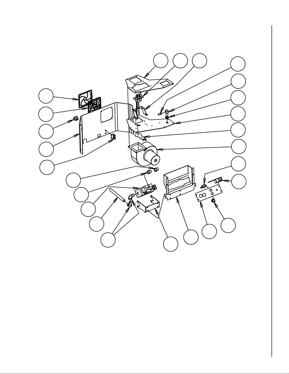
36
38
39
40
41
43
44
45
46
47
48
49
50
51
52
57
35
33
34
53
54
55
56
42
37
NO. DESCRIPTION
33 FLAME CONTROL EXTENSION
34 PILOT CONTROL EXTENSION
35 VALVE ASSY.
36 BLACK IRON PIPE
37 STREET ELBOW
38 BRACKET, VALVE
39 CONTROL PANEL
40 DASHBOARD
41 ON/OFF SWITCH
42 RHEOSTAT
43 PIEZO Igniter
NO. DESCRIPTION
44 BLOWER
45 SLIDER WASHER
46 CASSETTE PLATE
47 BULKHEAD SPACER
48 FITTING BULKHEAD
49 ORIFICE
50 PILOT ASSEMBLY BRACKET
51 PILOT ASSEMBLY
52 CASSETTE GASKET
53 FAN GRILL COVER
54 FAN GRILL MOUNT
NOTE: DIAGRAMS & ILLUSTRATIONS ARE NOT TO SCALE.
NO. DESCRIPTION
55 AC POWER PLUG
56 PEDESTAL BACK
57 THERMO. OUTLET BRACKET
29
Page 30

Wire Harness Diagram
POWER CORD
SNAP SWITCH
SPEED CONTROL
SWITCH
BLOWER
MALE SPADE 1/4"
FEMALE SPADE 1/4"
RING LUG CRIMP
W
H
T
FEMALE SPADE 1/4"
FEMALE SPADE 1/4"
x3
24"
Remote Thermostat Plug
Wht 5"
BLK 5"
GRN 24"
WHT 5"
BLK 18"
BLK 5"
BLK 16"
FEMALE SPADE 1/4"
MALE SPADE 1/4"
BLK 24"
FEMALE SPADE
1/4"
6ft
CAUTION: Label all wires prior to disconnection when servicing controls. Wiring errors can cause improper and
dangerous operation. Verify proper operation after servicing.
Figure 38
30
NOTE: DIAGRAMS & ILLUSTRATIONS ARE NOT TO SCALE.
Page 31

Replacement Parts List
Epic™ 33/40 (EPIC33/40)
Diagram No. Part No. Description
1 H3102 Front Door
2 H5835 Burner Support, Right
3 H5834 Burner Support, Left
4 H3137 Burner Pan
5,6,7 H5872 Brick Panel Set
8 H5836 Brick Panel Bracket
10,11 H3124 Heat Exchanger Kit
12,13 H6014 Side Door
14 H5875 Snap Switch
16,17,24,25,26 H6015 Large Relief Door Assembly
18 H6017 Top Cover
19 H5919 Flue Adapter 6-5/8”
20 H5909 Flue Adapter Gasket
22,23,24,25,26 H3127 Relief Door Assembly, Small
27 H3125 Door Latch Assembly
29 H3126 Magnet and Bracket Assembly
30 H6016 Control Door Assembly
32 H3125 Control Door Latch
33 H5969 Flame Control Extension Knob
34 H5968 Pilot Control Extension Knob
35, 37, 38, 50, 51, 52 H3138 Cassette Assembly, NG
H5942 Gas Control Valve NG
H5943 Regulator, NG
H5945 Regulator, LP
41 H5744 On/Off Switch, Round
42 H5742 Blower Speed Control (rheostat)
43 H5745 Piezo Igniter
H4635 Wall Thermostat, Digital, DWTK
70005 AC Remote Control Thermostat
H0251 DC Remote Control, Deluxe, Thermostat
44 H5888 Blower
48 H5896 Fitting Bulkhead
49 H5924 Orifice, NG #36, 33,000 BTU
49 H5973 Orifice, NG #31, 40,000 BTU
75355 Conversion Kit LP to NG
75352 Conversion Kit NG to LP
51 H5922 Pilot Assembly, NG or LP
52 H5907 Cassette Gasket
53,54 H3078 Blower Grill Assembly
55 H3079 A/C Power Cord
H5873 Log Set
H5863 Bag of Embers (volcanic stone)
H5864 Bag of Rockwool
70K99 Touch-Up Paint, Metallic Black (aerosol)
31
Page 32
Accessories
Trim Kits
Kits Include: Matching Trim for Glass (Upper and Lower)
Cat. No. Description
75348 Black Trim, EPIC-TRIM-B
75349 Gold Trim, EPIC-TRIM-G
75350 Brushed Nickel Trim, EPIC-TRIM-BN
75351
Black Nickel Trim, EPIC-TRIM-BKN
Gas Conversion Kits
Cat. No. Description
75355 Conversion Kit LP to NG
75352
70005 Remote Thermostat AC, RT-AC
H0251
H4635 Wall Thermostat, Digital, DWTK
Conversion Kit NG to LP
Misc
Remote Control, Deluxe Thermostat DC, RCL-STAT
32
NOTE: DIAGRAMS & ILLUSTRATIONS ARE NOT TO SCALE.
Page 33

Lighting Label
CAUTION: YOUR COUNTRY GAS APPLIANCE MUST ALWAYS BE OPERATED WITH GLASS DOOR IN PLACE.
STOP! Read the safety information above before proceeding.
1. Open the lower door. Make sure gas supply shut-off cocks are open
and ON/OFF Rocker Switch is “OFF”. If equipped with a thermostat,
set it to the lowest setting.
2. Turn off all electrical power to the appliance.
3. Push in Gas Control Knob slightly and turn clockwise to
“OFF”.
NOTE: Knob cannot be turned from “PILOT” to “OFF” unless Knob is pushed in slightly. Do not force.
4. Wait five (5) minutes to clear out any gas. If you smell gas, STOP! Follow “B” above. If you don’t smell gas continue.
5. Locate the pilot by looking at the center bottom of the back log. Blue flame will be seen when the pilot is lit.
6. Turn the gas control knob counterclockwise to the “PILOT” position.
7. Push the knob all the way in and hold in that position. Immediately light the pilot by pressing the igniter button
FOR YOUR SAFETY READ BEFORE OPERATING
1. To turn off the burner, switch the rocker switch to “OFF” or adjust the thermostat to a setting below room temperature (if installed). The pilot will remain lit for future burner ignition.
For complete shutdown: See “TO TURN OFF GAS TO APPLIANCE” above.
SHUTDOWN PROCEDURE
OPERATING INSTRUCTIONS
WARNING:
IF YOU DO NOT FOLLOW THESE INSTRUCTIONS EXACTLY, A FIRE OR EXPLOSION MAY RESULT CAUSING PROPERTY DAMAGE, INJURY OR LOSS OF LIFE.
CAUTION:
HOT WHILE IN OPERATION. DO NOT TOUCH. KEEP CHILDREN, FURNITURE, GASOLINE AND OTHER LIQUIDS WITH FLAMMABLE VAPORS AWAY. NEVER OPERATE UNIT WITH GLASS DOOR OFF OR ATTEMPT TO OPEN
THE DOOR WHILE HOT.
A. This appliance is equipped with a piezo ignition device to light the pilot. When lighting the pilot, follow these
instructions exactly.
B. BEFORE LIGHTING, smell around the appliance area for gas. Be sure to smell next to the floor because some gas is
heavier than air and will settle on the floor.
WHAT TO DO IF YOU SMELL GAS:
• DO NOT try to light the appliance.
• DO NOT touch any electric switch; do not use any phone in the building.
1. Turn off the “ON/OFF” rocker switch and/or thermostat (if installed).
2. Turn off electric power to the appliance if service is to be performed.
3. Turn gas control knob clockwise to "OFF". Do not force.
This appliance needs fresh air for safe operation and must be installed so there are provisions for adequate combustion and ventilation air. See Installation and Operation Manual accompanying
appliance.
WARNING: Improper installation, adjustment, alteration, service or maintenance can cause injury or property damage. For assistance or additional information,
consult a qualified installer, service agency or your gas supplier.
Operation of this appliance when not connected to a properly installed and maintained venting system can result in carbon monoxide (CO) poisoning and possible death.
TO TURN OFF GAS TO APPLIANCE
Part No. #36252 Rev. A, 04/07
• Immediately call your gas supplier from a neighbor's phone. Follow the gas supplier's instructions.
• If you cannot reach your gas supplier, call the fire department.
C. Use only your hand to push in or turn the gas control knob. Never use any tool. If the knob will not push in or turn
by hand, don't try to repair it, call a qualified service technician. Force or attempted repair may result in a fire or
explosion.
D. DO NOT use this appliance if any part has been under water. Immediately call a qualified service technician to inspect
the appliance and to replace any part of the control system and any gas control which has been under water.
ON
OFF
PILOT
HI
LOW
GAS CONTROL
ON/OFF
FLAME HEIGHT
several times until pilot is lit. Continue to hold the knob in for about 30 seconds after the pilot is lit. Release knob and
it will pop back out.
Pilot should remain lit. If it goes out, repeat steps 4-8 holding knob in an additional 15 seconds after pilot is lit.
• If knob does not pop out when released, stop and immediately call your service technician or gas supplier.
• If the pilot will not stay lit after several tries, turn the gas control knob to
“OFF” and call your service technician or your gas supplier.
8. After pilot is lit, turn gas control counterclockwise to “ON”. Knob
can only be turned “ON” if the knob has popped out.
9. To turn burner on, turn “ON/OFF” rocker switch to “ON” or set the thermostat
to the desired temperature above room temperature.
10. Adjust the flame height (and heat output) by turning the flame height knob
clockwise for reduced flame and counterclockwise for full
flame.
11. Turn on all electrical power to the appliance.
12. Set the blower to the desired air flow after it turns on when the appliance reaches operating temperature.
PILOT ASSEMBLY
Gas Pilot Hood
Igniter
Thermocouple
Thermopile
IGN
LENNOX
NOTE: DIAGRAMS & ILLUSTRATIONS ARE NOT TO SCALE.
33
Page 34
Safety / Listing Label
MODEL
MODÈLE
EPIC™ NG 40
MANUFACTURED BY:
LENNOX HEARTH PRODUCTS
PO BOX 987
AUBURN, WA., USA 98071
SERIAL NO.
NUMÉRO DE
SÉRIE
Report No. / Número de Rapport
050-S-21b-5
RATINGS
EPIC 33 EPIC 40
NATURAL GAS LP GAS NATURAL GAS LP GAS
MAXIMUM INPUT BTUH 0-2,000 FT (0-610 M)* 33,000 / 23,000 31,000 / 24,000 40,000 / 27,000 39,000 / 30,000
ORIFICE (DMS) 0-2,000 FT (0-610 M)* #36/.106 IN. #52/.064 IN. #31/.120 IN. #49/.073 IN.
MANIFOLD PRESSURE (IN. WC)
3.5 / 1.7 10.0 / 5.4 3.5 / 1.7 10.0 / 5.4
MIN. INLET PRESSURE (IN. WC) 5.0 11.0 5.0 11.0
*UNIT FACTORY EQUIPPED FOR 0-2000 FT/0-610 M, IN CANADA 0-4500 FT/0-1370 M
ELECTRICAL RATING: 120 VAC, 60 HZ, LESS THAN 2 AMPS
MINIMUM CLEARANCES - TO COMBUSTIBLES IN INCHES
CAUTION:
HOT WHILE IN OPERATION. DO NOT TOUCH. SEVERE BURNS MAY RESULT. KEEP
CHILDREN, CLOTHING, FURNITURE, GASOLINE AND OTHER LIQUIDS HAVING FLAMMABLE VAPORS
AWAY. KEEP BURNER AND CONTROL COMPARTMENT CLEAN. SEE INSTALLATION AND OPERATING
INSTRUCTIONS ACCOMPANYING APPLIANCE. FOR USE WITH GLASS DOORS CERTIFIED WITH THIS
APPLIANCE ONLY. DO NOT OPERATE THE APPLIANCE WITH GLASS REMOVED, CRACKED OR BROKEN.
REPLACEMENT OF THE PANEL(S) SHOULD BE DONE BY A LICENSED OR QUALIFIED PERSON.
WARNING: IMPROPER INSTALLATION, ADJUSTMENT, ALTERATION, SERVICE OR MAINTENANCE CAN
CAUSE INJURY OR PROPERTY DAMAGE. REFER TO THE OWNER’S INFORMATION MANUAL PROVIDED
WITH THIS APPLIANCE. FOR ASSISTANCE OR ADDITIONAL INFORMATION CONSULT A QUALIFIED
INSTALLER, SERVICE AGENCY OR GAS SUPPLIER.
ALCOVE DIMENSIONS
MAXIMUM DEPTH 48” (1219mm)
MINIMUM WIDTH 48” (1219mm)
MINIMUM HEIGHT 69” (1753mm)
SEE OWNER’S MANUAL FOR
OTHER ALCOVE CLEARANCE
CONFIGURATIONS
HEARTH PROTECTION
SEE INSTRUCTION MANUAL
INSTALLATION
4" (102mm)
24.5" (622mm)
12.5"
(318mm)
90°
4.5"
(114mm)
4.5"
(114mm)
INSTALLATION
10.5" (267mm)
Part No./ No. Pièce #36247 Rev. B, 03/08 DO NOT REMOVE OR COVER THIS LABEL Made in U.S.A.
DATE OF MANUFACTURE / DATE DE FABRICATION
2008 2010 20112009
JANV
JAN
FEVR
FEB
MARS
MAR
AVR
APR
MAI
MAY
JUIN
JUN
JUIL
JUL
AOÛT
AUG
SEPT
SEP
OCT
OCT
NOV
NOV
DEC
DEC
N’ENLEVEZ PAS OU NE COUVREZ PAS CETTE ÉTIQUETTE Fabriqué aux U.S.A. IGN 08-0711
DANGER:
CET APPAREIL DÉGAGE DES TEMPÉRATURES ÉLEVÉES ET DEVRAIT ÊTRE INSTALLÉ
À L’ÉCART DES ENDROITS TRÈS PASSANTS ET LOIN DES MEUBLES ET RIDEAUX. SURVEILLEZ LES
ENFANTS QUI SE TROUVENT DANS LA PIÈCE. GARDEZ LA ZONE AUTOUR DU FOYER EXEMPTE DE
MATÉRIAUX COMBUSTIBLES, D’ESSENCE ET AUTRES VAPEURS ET LIQUIDES INFLAMMABLES.
MAINTENEZ LE BRÛLEUR ET LE BOÎTIER DES COMMANDES PROPRE EN TOUT TEMPS. VOIR LES
MANUELS D’INSTALLATION ET D’ENTRETIEN QUI ACCOMPAGNENT L’APPAREIL. SEUL LE PANNEAU
VITRÉ FOURNI PAR LE MANUFACTURIER PEUT ÊTRE UTILISÉ AVEC CET APPAREIL. EN AUCUN CAS,
L’APPAREIL NE PEUT ÊTRE UTILISÉ SANS LA VITRE OU AVEC LA VITRE BRISÉE. LE REMPLACEMENT DE
LA VITRE DOIT ÊTRE EFFECTUÉ PAR UN TECHNICIEN DE SERVICE QUALIFIÉ.
AVERTISSEMENT: UNE INSTALLATION INADÉQUATE DE MÊME QU’UN AJUSTEMENT, UNE MODIFICATION,
UNE RÉPARATION OU UN ENTRETIEN INCORRECTS PEUVENT CAUSER DES BLESSURES OU DOMMAGES
À LA PROPRIÉTÉ. RÉFÉREZ-VOUS AU MANUEL D’ENTRETIEN LIVRÉ AVEC CET APPAREIL. POUR DE
L’ASSISTANCE, CONSULTEZ UN INSTALLATEUR QUALIFIÉ, UNE ENTREPRISE DE SERVICE OU UN
FOURNISSEUR DE GAZ.
DIMENSIONS – ALCOVE
PROFONDEUR MAXIMUM: 48 PO. (1219mm)
LARGEUR MAXIMUM : 48 PO. (1219mm)
HAUTEUR MAXIMUM : 69 PO. (1753mm)
REFEREZ VOUS AU MANUEL D’INSTALLATION
POUR TOUT AUTRE DEGAGEMENT REQUIS.
PROTECTIONS AU PLANCHER : REFEREZ
VOUS AU MANUEL D’INSTALLATION
DÉGAGEMENTS AUX COMBUSTIBLES - POUCES
HOMOLOGUÉ FOYER RADIANT PRÉFABRIQUÉ AU GAZ -NE PAS UTILISER AVEC DU COMBUSTIBLE
SOLIDE
MAY BE INSTALLED IN RESIDENTIAL BEDROOMS AND MANUFACTURED (MOBILE) HOMES.
TESTÉ SELON LA NORME ANSI Z21.88-2005/CSA 2.33-2005 «FOYER RADIANT AU GAZ», UL307B, CSA P.4.1-02, ET CGA 2.17-M91.
CET APPAREIL DOIT ÊTRE INSTALLÉ CONFORMÉMENT AUX EXIGENCES DES CODES RÉGIONAUX ET DU CODE D’INSTALLATION
ANSI NFPA 5 4-DERNIÈRE ÉDITION (ETATS-UNIS) , OU CAN/CGA -B149.1-DERN IÈRE É DITION (CANADA) PO UR LES MAISO N
MOBILE LE STAN DARD DE SÉCURITÉ EST TITLE 24CFR, PART 3280 . CET APPAREIL DOI T ÊTRE INSTALLER SELON LES
SPÉCIFICATIONS DU MANUFACTURIER.
CET APPAREIL DOIT ÊTRE UTILISÉ AVEC LE TYPE DE GAZ INDIQUÉ SUR LA PLAQUE SIGNALÉTIQUE ET PEUT ÊTRE INSTALLÉ
DANS UNE MAISON PRÉUSINÉE OU DANS UNE MAISON MOBILE FIXE, LÀ OÙ LES CODES RÉGIONAUX LE PERMETTENT. VOIR
LE MANUEL D ’ENTRETIEN POUR PL US DE DÉTAILS. CET APPAREIL NE P EUT PAS ÊTRE CONVERTI POUR L’USAGE AVEC
D’AUTRES TYPES DE GAZ À MOINS D’UTILISER UNE TROUSSE DE CONVERSION HOMOLOGUÉE.
DANGER: RISQUE DE CHOC ÉLECTRIQUE. DÉBRANCHEZ L’APPAREIL AVANT D’EN FAIRE L’ENTRETIEN.
SI L’APPAREIL REQUIERT UN BRANCHEMENT ÉLETRIQUE, LES RACCORDEMENTS ET LA MISE À LA TERRE DOIVENT ÉTR E
CONFORMES AUX EXIGENCES DES CODES RÉGIONAUX ET DU CODE D’INSTALLATION ANSI/NFPA 70 OU CSA C22-1.
POSITION
EN COIN
POSITION PARALLÈLE OU
POSITION DE L'ALCÔVE
VENTED GAS FIREPLACE HEATER - NOT FOR USE WITH SOLID FUEL
MAY BE INSTALLED IN RESIDENTIAL BEDROOMS AND MANUFACTURED (MOBILE) HOMES.
TESTED TO ANSI Z21.88-2005/CSA 2 .33-2005 “VENTED GAS FIREPLACE HEATERS”, UL307b, CSA P.4.1-02,
AND CGA 2.17-M91.
THIS APPLIANCE MUST BE INSTALLED IN ACCORDANCE WITH LOCAL CODES, IF ANY. IF NOT, FOLLOW THE
CURRENT ANSI Z223.1/NF PA 54-LATEST EDITION (USA) OR CAN/CGA B149.1-LATEST E DITION (CANADA)
AND SAFETY STANDARD , TITLE 24 C FR, PART 3280 FOR MOBILE HOMES. ALSO, APPLIANCE MUST BE
INSTALLED IN ACCORDANCE WITH THE MANUFACTURER’S INSTALLATION INSTRUCTIONS.
THIS APPLIANCE IS ONLY FOR USE WITH THE TYPE OF GAS INDICATED ON THE RATING PLATE AND MAY
BE INSTALLED IN AN AFTERMARKET, PERMANENTLY LOCATED, MANUFACTURED (MOBILE) HOME WHERE
NOT PROHIBI TED BY LOCAL CODES . SEE OWNER ’S MA NUAL F OR DETAIL S. TH IS APPL IANCE IS NO T
CONVERTIBLE FOR USE WITH OTHER GASES, UNLESS A CERTIFIED KIT IS USED.
DANGER: RISK OF ELECTRICAL SHOCK. DISCONNECT POWER BEFORE SERVICING UNIT.
IF ELECTRICALLY CONNECTED, CONNECTIONS AND GROUNDING MUST BE IN ACCORDANCE WITH LOCAL
CODES, IF ANY. IF NOT, FOLLOW THE CURRENT NATIONAL ELECTRICA L CODE ANSI/NF PA 70-LATEST
EDITION (USA) OR CSA C22-1-LATEST EDITION (CANADA).
FACTORY EQUIPPED FOR NATURAL GAS. IF CONTROL PANEL
CONTRADICTS THIS LABEL, UNIT FUEL TYPE HAS BEEN CONVERTED.
CET APPAREIL EST MUNI D’ÉQUIPEMENT POUR L’USAGE DU GAZ NATUREL.
SI L’ÉTIQUETTE DU PANNEAU DES COMMANDES CONTREDIT CETTE ÉTIQUETTE,
C’EST QUE LE TYPE DE CARBURANT DE CET APPAREIL A ÉTÉ CONVERTI.
VENTING: THIS APPLIANCE MUST BE PROPERLY CON NECTED TO A VENTING SYSTEM IN ACCORDANCE
WITH THE MANUFACTURER’S INSTRUCTIONS. SEE MANUFACTURER’S INSTALLATION INSTRUCTIONS FOR
APPROVED PIPE BRANDS AND PIPE SEALING PROCEDURES.
FOR ALTITUDES ABOVE 2,000 FT/610M (IN CANADA 4500 FT/1370M) DE-RATE THE APPLIANCE BY FOUR (4)%
FOR EVERY 1,000 FT (405 M).
THIS VENTED GAS FIREPLACE HEATER IS NOT FOR USE WITH AIR FILTERS.
SPÉCIFICATIONS
Modèle
EPIC 33
Modèle
EPIC 40
GAZ NATUREL GAZ PROPANE GAZ NATUREL GAZ PROPANE
ENTRÉE MAX/MIN BTU/HR 0-4500 pi
(0-1370 M)*
33000/ 23000 31000/ 24000 40000/ 27000 39000/ 30000
ORIFICE (DMS) 0-4500 pi (0-1370 M)*
#36/.106" #52/.064" #31/.120" #49/.073"
PRESSION À LA SORTIE (IN. WC/C.E.)
3.5 / 1.7 10.0 / 5.4 3.5 / 1.7 10.0 / 5.4
PRESSION MINIMUM D’ENTRÉE DU GAZ
(IN. WC/C.E.)
5.0 11.0 5.0 11.0
* L’APPAREIL PRÉUSINÉ EST MUNI D’ÉQUIPEMENT POUR 0-2000 PIEDS (0-610 M). AU CANADA 0-4500 PIEDS (0-1370M).
SPÉCIFICATIONS ÉLECTRIQUE 120 VCA, 60 HZ, MOINS DE 2 AMPÈRES
CON DUIT: CET APPA REIL DOI T ETRE IN STALLER S EULEM ENT AVEC UN CO NDUIT D’EVAC UATION
RECOMMANDE PAR LE MANUFACTURIER. TOUJOURS SE REFERER AU MANUEL D’INSTALLATION.
EN ALTITUDE, AU-DELÀ DE 2000 PI/610 M, (AU CANADA 0-4500 PI/0-1370M) LA CAPACITÉ ÉNERGÉTIQUE DE
L’APPAREIL DIMINUE DE QUATRE (4)% POUR CHAQUE 1000 PI (405 M).
CE FOYER RADIANT AU GAZ À ÉVACUATION N’EST PAS CONÇU POUR ÊTRE UTILISÉ AVEC DES FILTRES À AIR.
ALCOVE OR PARALLEL
INSTALLATION
CORNER INSTALLATION
INSTALLATION
4" (102mm)
24.5" (622mm)
12.5"
(318mm)
Mur Combustible
Mur Combustible
90°
4.5"
(114mm)
4.5"
(114mm)
INSTALLATION
10.5" (267mm)
Mur Combustible
Mur Combustible
Combustible Wall
Combustible Wall
Combustible Wall
Combustible Wall
34
NOTE: DIAGRAMS & ILLUSTRATIONS ARE NOT TO SCALE.
Page 35

Notes
NOTE: DIAGRAMS & ILLUSTRATIONS ARE NOT TO SCALE.
35
Page 36

WARRANTY
�
Your gas stove is covered by a limited warranty (provided with appliance).
Please read the warranty to be familiar with its coverage.
Retain this manual. File it with your other documents for future refer
ence.
PRODUCT REFERENCE INFORMATION
We recommend that you record the following important information
about your appliance. Please contact your Lennox Hearth Products dealer
for any questions or concerns. For the number of your nearest Lennox
Hearth Products dealer, please call 1-800-9-LENNOX.
REPLACEMENT PARTS
See Page 31 for a complete replacement parts list. Use only parts supplied from the manufacturer.
Your Stove's Model Number __________________________________________
Your Stove's Serial Number ___________________________________________
Normally, all parts should be ordered through your Lennox Hearth
Products distributor or dealer. Parts will be shipped at prevailing prices
at time of order.
When ordering repair parts, always give the following information:
-
1. The model number of the appliance.
2. The serial number of the appliance.
3. The part number.
4. The description of the part.
5. The quantity required.
6. The installation date of the appliance.
If you encounter any problems or have any questions concerning the
installation or application of this system, please contact your dealer.
LENNOX HEARTH PRODUCTS
1110 West Taft Avenue
Orange, CA 92865
Visit us at www.Lennox.com
The Date On Which Your Stove Was Installed _____________________________
The Type of Gas Your Stove's Uses _____________________________________
Your Dealer's Name _________________________________________________
Fuel Type (Check one) cNatural Gas cPropane Gas (LP)
Lennox™ reserves the right to make changes at any time, without notice, in design,
materials, specifications, prices and also to discontinue colors, styles and products.
Consult your local distributor for fireplace code information.
Printed in U.S.A. © 2007 Lennox Hearth Products
P/N 775,223M REV. B 03/2008
36
1110 West Taft Avenue • Orange, CA 92865
 Loading...