

Page 1
PRODUCT LITERATURE
¤
1997 Lennox Industries Inc.
'DOODV 7H[DV
0
6XSHUVHGHV
£
8*)
6(5,(6
*$6 )851$&(
,I WKH LQIRUPDWLRQ LQ WKLV PDQXDO LV QRW
IROORZHG H[DFWO\ D ILUH RU H[SORVLRQ
PD\ UHVXOW FDXVLQJ SURSHUW\ GDPDJH
SHUVRQDO LQMXU\ RU ORVV RI OLIH
'R QRW VWRUH RU XVH JDVROLQH RU RWKHU
IODPPDEOH YDSRUV DQG OLTXLGV LQ WKH
YLFLQLW\ RI WKLV RU DQ\ RWKHU DSSOLDQFH
,QVWDOODWLRQ DQG VHUYLFH PXVW EH SHU
IRUPHG E\ D TXDOLILHG LQVWDOOHU VHUYLFH
DJHQF\ RU WKH JDV VXSSOLHU
:$51,1*
:+$7 72 '2 ,) <28 60(// *$6
-
'R QRW WU\ WR OLJKW DQ\ DSSOLDQFH
-
([WLQJXLVK DQ\ RSHQ IODPHV
-
'R QRW WRXFK DQ\ HOHFWULFDO VZLWFK GR QRW
XVH DQ\ SKRQH LQ \RXU EXLOGLQJ
-
,PPHGLDWHO\ FDOO \RXU JDV VXSSOLHU IURP D
QHLJKERUV SKRQH )ROORZ WKH JDV VXSSOLHUV
LQVWUXFWLRQV
-
,I \RX FDQQRW UHDFK \RXU JDV VXSSOLHU FDOO
WKH ILUH GHSDUWPHQW
/LWKR 86$
Page 2
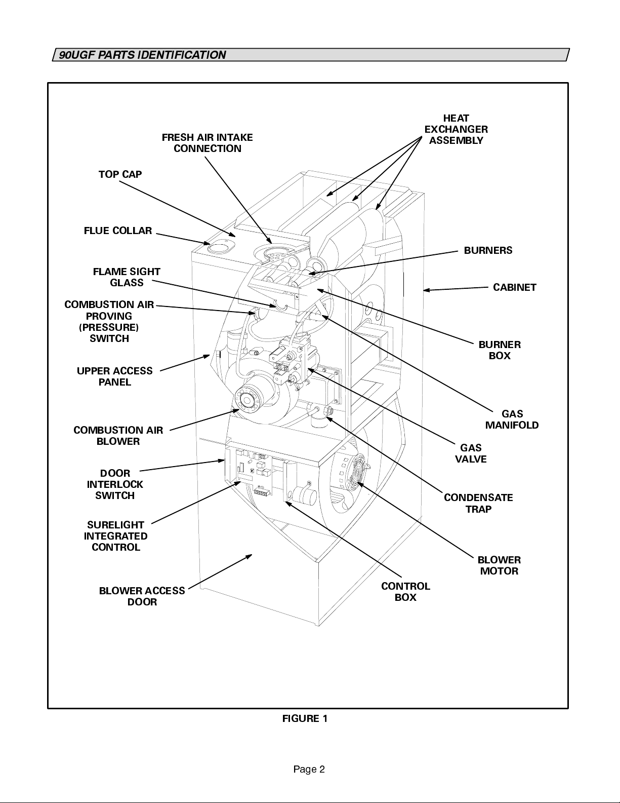
8*) 3$576 ,'(17,),&$7,21
FRESH AIR INTAKE
CONNECTION
TOP CAP
FLUE COLLAR
FLAME SIGHT
GLASS
COMBUSTION AIR
PROVING
(PRESSURE)
SWITCH
UPPER ACCESS
PANEL
HEAT
EXCHANGER
ASSEMBLY
BURNERS
CABINET
BURNER
BOX
COMBUSTION AIR
BLOWER
DOOR
INTERLOCK
SWITCH
SURELIGHT
INTEGRATED
CONTROL
BLOWER ACCESS
DOOR
GAS
MANIFOLD
GAS
VALVE
CONDENSATE
TRAP
BLOWER
MOTOR
CONTROL
BOX
FIGURE 1
3DJH
Page 3

WARNING
Product contains fiberglass wool.
Disturbing the insulation in this product during
installation, maintenance, or repair will expose
you to fiberglass wool. Breathing this may
cause lung cancer. (Fiberglass wool is known to
the State of California to cause cancer.)
Fiberglass wool may also cause respiratory,
skin, and eye irritation.
To reduce exposure to this substance or for fur-
ther information, consult material safety data
sheets available from address shown below, or
contact your supervisor.
Lennox Industries Inc.
P.O. Box 7999
Dallas, TX 75379--9900
00
WARNING
Do not set thermostat below 60EF (16EC) in heat-
ing mode. Setting thermostat below 60EF (16EC)
reduces the number of heating cycles. Damage
to the unit may occur that is not covered by the
warranty.
WARNING
If overheating occurs or if gas supply fails to shut
off, shut off the manual gas valve to the ap-
pliance before shutting off electrical supply.
WARNING
,03257$17 ',5(&7,216
1 -- Keep the furnace area clear and free of combus-
tible material, gasoline, and other flammable va-
pors and liquids. If installed in an insulated area,
furnace must be kept free of insulating material.
Insulating material may be combustible.
2 -- DO NOT obstruct air flow to unit. Unit must re-
ceive an unobstructed flow of combustion and
ventilating air.
3 -- DO NOT store chlorine or fluorine products near
unitorintroducetheseproducts into thecombus-
tion air. These products can cause furnace corro-
sion.
4--
DO NOT draw return air from a room where this
furnace, or any other gas appliance (ie., a water
heater), is installed.
from a room, a negative pressure is createdin the
room. If a gas appliance is operating in a room
with negative pressure, the flue products can be
pulled back down the vent pipe and into the
room. This reverse flowofthe flue gas may result
in incomplete combustion and the formation of
carbon monoxide gas. This toxic gas might then
be distributed throughout the house by the fur-
nace duct system.
Your furnace is a gas appliance.
gas supplied to the unit be completely burned to
avoid the production of carbon monoxide gas. Com-
plete combustion of the gas requires, but is not lim-
ited to, correct gas pressure and gas flow rate, ade-
quate combustion, air, and proper venting.
When return air is drawn
It is critical that the
:$51,1*
&DUERQ PRQR[LGH JDV LV LQYLVLEOH RGRUOHVV DQG
WR[LF
Do not use this furnace if any part has been
underwater. Immediately call a qualified service
technician to inspect the furnace and to replace
any part of the control system and any gas con-
trol which has been under water.
CAUTION
Before attempting to perform any service or
maintenance, turn the electrical power to unit
OFF at disconnect switch.
IMPORTANT
Any additions, changes, or conversions required
in order for the appliance to satisfactorily meet
the application needs must be made by a Lennox
service technician using factory specified and ap-
proved parts.
Exposure to this gas can cause personal injury and
even death to all occupants, including pets. Any item
that is powered by or gives off heat from a combus-
tion process (including lawn mowers, automobiles,
and fireplaces) has the potential to produce carbon
monoxide gas. Because of this,
the use of a carbon monoxide detector in your home,
even if you do not own gas appliances.
tectors are available at reasonable retail prices. Con-
tact your independent Lennox dealer for more details
about this investment in your safety.
Your furnace is designed to meet standards set byna-
tional agencies, and to operate safely when properly
installed and maintained. However, the units perfor-
mance can be greatly impacted by the individual
installation and the operating environment. It is your
responsibility to ensure that this appliance is main-
3DJH
Lennox recommends
Reliable de-
Page 4
tained. Proper maintenance is critical for your safety
and the satisfactory operation of the product.
Lennox
strongly recommends annual inspection and mainte-
nance of this appliance.
Contact your independent
Lennox dealer for an inspection bya qualified service
technician.
/,*+7,1* ,1)250$7,21 $1' 23(5$7,21
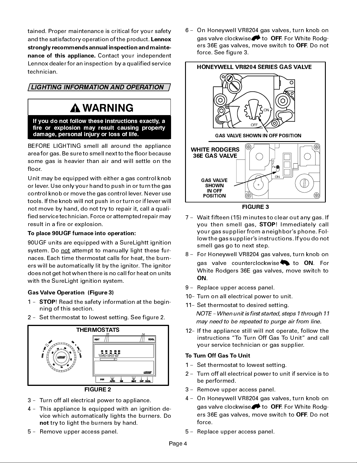
6 -- On Honeywell VR8204 gas valves, turn knob on
gas valve clockwise
ers 36E gas valves, move switch to
to
OFF
. For White Rodg-
OFF
.Donot
force. See figure 3.
HONEYWELL VR8204 SERIES GAS VALVE
:$51,1*
,I \RX GR QRW IROORZ WKHVH LQVWUXFWLRQV H[DFWO\ D
ILUH RU H[SORVLRQ PD\ UHVXOW FDXVLQJ SURSHUW\
GDPDJH SHUVRQDO LQMXU\ RU ORVV RI OLIH
BEFORE LIGHTING smell all around the appliance
area for gas. Be sure to smell next to the floor because
some gas is heavier than air and will settle on the
floor.
Unit may be equipped with either a gas control knob
or lever.Use only your hand to push in or turn thegas
control knob or move the gas control lever. Never use
tools. If the knob will not push in or turn or if lever will
not move by hand, do not try to repair it, call a quali-
fied service technician. Force or attempted repair may
result in a fire or explosion.
To place 90UGF furnace into operation:
90UGF units are equipped with a SureLightt ignition
system. Do not
naces. Each time thermostat calls for heat, the burn-
ers will be automatically lit by the ignitor. The ignitor
does not get hot when there is nocall for heat on units
with the SureLight ignition system.
Gas Valve Operation (Figure 3)
1--
STOP
ning of this section.
2 -- Set thermostat to lowest setting. See figure 2.
attempt to manually light these fur-
! Read the safety information at the begin-
7+(50267$76
21
2))
GAS VALVE SHOWN IN OFF POSITION
WHITE RODGERS
36E GAS VALVE
GAS VALVE
SHOWN
IN OFF
POSITION
),*85(
7 -- Wait fifteen (15) minutes to clear out any gas. If
you then smell gas,
STOP
! Immediately call
your gas supplier from a neighborsphone. Fol-
lowthegass uppliersinstructions.Ifyou do not
smell gas go to next step.
8 -- For Honeywell VR8204 gas valves, turn knob on
to
ON
gas valve counterclockwise
. For
White Rodgers 36E gas valves, move switch to
ON
.
9 -- Replace upper access panel.
10-- Turn on all electrical power to unit.
11-- Set thermostat to desired setting.
NO
TE -- When unitis first started, steps 1 through 11
may need to be repeated to purge air from line.
12-- If the appliance still will not operate, follow the
instructions To Turn Off Gas To Unit and call
your service technician or gas supplier.
),*85(
3 -- Turn off all electrical power to appliance.
4 -- This appliance Is equipped with an ignition de-
vice which automatically lights the burners. Do
not
try to light the burners by hand.
5 -- Remove upper access panel.
To Turn Off Gas To Unit
1 -- Set thermostat to lowest setting.
2 -- Turn off all electrical power to unit if service is to
be performed.
3 -- Remove upper access panel.
4 -- On Honeywell VR8204 gas valves, turn knob on
to
OFF
gas valve clockwise
. For White Rodg-
ers 36E gas valves, move switch to
force.
5 -- Replace upper access panel.
3DJH
OFF
.Donot
Page 5
),/7(56
A filtermustbeinplaceanytime the unit is in opera-
tion. The filter may be located in the unit (optional
kit) or installed in a return air grille. Ask your dealer
to show you the filter location. The filter should be
inspected monthly and cleaned when necessary to
assure proper furnace operation.
Filters used inside the 90UGF series unit are available
from Lennox and must be ordered separately. These
foam filters may be cleaned for reuse. If replac ement
is necessary, order Lennox part no. 31J81 for 14 X
25 (356 X 635mm) filter for 90UGF--50 and --75 units
andP--8--7831for20X 25 (508 X635mm)filter used
with 90UGF--100 and --125 units. Use the following
procedure to clean filter. Refer to figure 1.
In--Unit Filter with Bottom Return Air
1 -- Turn off electric power to furnace.
2 -- Remove blower access panel.
3 -- Remove filter by pressing side filter clips and
pulling filter up and out. See figure 4.
%27720 5(7851 ),/7(5 ,167$//$7,21
5($5 ),/7(5 &/,3
)851$&(
%$&.
6,'( ),/7(5 &/,36
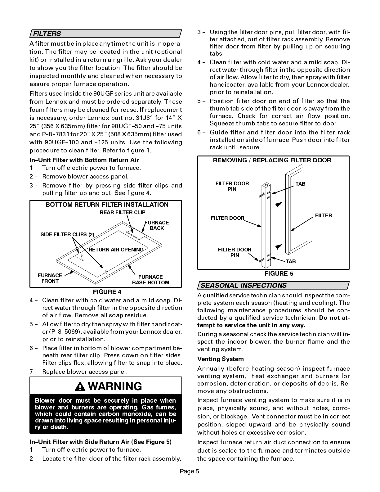
3 -- Using the filter door pins, pull filter door, with fil-
ter attached, out of filter rack assembly. Remove
filter door from filter by pulling up on securing
tabs.
4 -- Clean filter with cold water and a mild soap. Di-
rect water through filter in the opposite direction
of airflow.Allow filter to dry,then spray with filter
handicoater, available from your Lennox dealer,
prior to reinstallation.
5 -- Position filter door on end of filter so that the
thumb tab side of the filter door is away from the
furnace. Check for correct air flow position.
Squeeze thumb tabs to secure filter to door.
6 -- Guide filter and filter door into the filter rack
installedonside of furnace.Pushdoor into filter
rack until secure.
5(029,1* 5(3/$&,1* ),/7(5 '225
),/7(5 '225
3,1
),/7(5 '225
7$%
),/7(5
5(7851 $,5 23(1,1*
)851$&(
)5217
)851$&(
%$6( %27720
),*85(
4 -- Clean filter with cold water and a mild soap. Di-
rect water through filter in the opposite direction
of air flow. Remove all soap residue.
5 -- Allow filter to dry thenspraywithfilterhandicoat-
er (P--8--5069), available from your Lennox dealer,
prior to reinstallation.
6 -- Place filter in bottom of blower compartment be-
neath rear filter clip. Press down on filter sides.
Filter clips flex, allowing filter to snap into place.
7 -- Replace blower access panel.
:$51,1*
%ORZHU GRRU PXVW EH VHFXUHO\ LQ SODFH ZKHQ
EORZHU DQG EXUQHUV DUH RSHUDWLQJ *DV IXPHV
ZKLFK FRXOG FRQWDLQ FDUERQ PRQR[LGH FDQ EH
GUDZQ LQWR OLYLQJ VSDFH UHVXOWLQJ LQ SHUVRQDO LQMX
U\ RU GHDWK
In--Unit Filter with Side Return Air (See Figure 5)
1 -- Turn off electric power to furnace.
2 -- Locate the filter door of the filter rack assembly.
),/7(5 '225
3,1
7$%
),*85(
6($621$/ ,163(&7,216
A qualifiedservice technician should inspect the com-
plete system each season (heating and cooling). The
following maintenance procedures should be con-
ducted by a qualified service technician.
tempt to service the unit in any way.
During a seasonal check the service technician will in-
spect the indoor blower, the burner flame and the
venting system.
Venting System
Annually (before heating s eason) inspect furnace
venting system, heat exchanger and burners for
corrosion, deterioration, or deposits of debris. Re-
move any obstructions .
Inspect furnace venting system to make sure it is in
place, physically sound, and without holes, corro-
sion, or blockage. Vent connector must be in correct
position, sloped upward and be physically sound
without holes or excessive corrosion.
Inspect furnace return air duct connection to ensure
duct is sealed to the furnace and terminates outside
the space containing the furnace.
Do not at-
3DJH
Page 6

Inspect the physical support ofthe furnace to guaran-
tee that it is sound without sagging, cracks or gaps
around base and it maintains seal between base and
support.
Inspect and clean the condensate traps and drain.
Blower
Check and clean blower wheel for any debris. Blower
motor is pre-lubricated for extended bearing life. No
further lubrication is needed.
Burner Flame
&$87,21
8VLQJ IODPH VLJKW JOD VV FKHFN EXUQHU IODPH
SHULRGLFDOO\ WR HQVXUH SURSHU RSHUDWLRQ
-
,
f you experience headache, nausea, fatigue, or
dizziness, the cause could be exposure to carbon
monoxide gas. This is often misdiagnosed as the
flu because symptoms are similar. If you suffer
from flu--like symptoms that are exaggerated at
home, but seem to subside while you are away
from the house, exposure to carbon monoxide
could be the cause.
Your vigilance may pay off in early detection of a
problem before either personal injury or property
damage occurs. Do not hesitate to contact a qualified
service technician as an investment in your well be-
ing.
3/$11(' 6(59,&(
Burner Flame
---- Start burner and allow it to operate
for a few minutes to establish normal burning condi-
tions. Check burner flame by observation. Flame
should be predominantly blue in color and strong in
appearance.
Contact your Lennox dealer for aperiodic unit inspec-
tion by a qualified service technician.
6(59,&( 5(0,1'(5
Call your Lennox service technician if unit is inopera-
tive. Before calling, always check the following to be
sure service is required.
1 -- Check that electrical disconnect switches are
ON.
2 -- Check room thermostat for proper setting.
3 -- Replace any blown fuses or resetcircuit breakers.
4 -- Gas valve should beON.
5 -- Air filter should not be plugged limiting air flow.
6 -- Is gas turned on at meter?
7 -- Is manual main shut-off valve open?
6$)(7< 35(&$87,216
If you discover any of the following, shut down your
unit, and contact an independent Lennox dealer for
an inspection by a qualified technician.
If you repeatedly hear any new or unfamiliar
-
sounds while your unit is operating, there may be a
problem. For example, poorly performing burners
can produce unfamiliar noises.
If you smell any unusual odors, your unit may be
-
operating improperly. For example, units can give
off unfamiliar odors if components are required to
operate in abnormal conditions.
Look for visible signs of a malfunctioning unit. Ex-
-
amples include unusual amounts of condensate
on windows inside your house, visibly burnt com-
ponents or unusual dirt or rust accumulations on
the vent pipe or in the unit.
You should expect a service technician to check the
following items during an annual inspection. Power
to the unit must be shut off forthe servicetechnicians
safety.
Fresh air grilles and louvers
(on the unit and in the
room where the furnace is installed) -- Must be open
and unobstructed to provide combustion air.
Burners
-- Must be inspected for rust, dirt, or signs of
water.
Vent pipe
-- Must be inspected for dirt, signs of water,
damaged or sagging unsupported pipe, or discon-
nected joints.
Unit appearance
-- Must be inspected for dirt, signs of
water, burnt or damaged wires, or components.
Blower access door
-- Must be properly in place and
provide a seal between the return air and the room
where the furnace is installed.
Return air duct
-- Must be properly attached and pro-
vide an airtight seal to unit.
Operating performance
-- Unit must be observed dur-
ing operation to monitor proper performance of the
unit and the vent system.
Combustion gases
-- Flue products must be analyzed
and compared to the unit specifications.
Problems detected during the inspection may make it
necessary to temporarily shut down the furnace until
the items can be repaired or replaced.
Payattentiontoyourfurnace.
Situations can arise be-
tween annual furnace inspections that may result in
unsafe operation. For instance, items innocently
stored next to the furnace may obstruct the combus-
tion air supply. This could cause incomplete combus-
tion and the production of carbon monoxide gas.
3
DJH
 Loading...