

Page 1

AX45Q
Intel® Q45 LGA775 socket for Intel® Core™2 Quad ATX
Motherboard
User’s Manual
Ver. 1.00
Page 2

AX45Q
Contents
Safety information ............................................................................................................. 4
About this guide ................................................................................................................ 5
Typography ........................................................................................................................ 6
AX45Q specifications summary ....................................................................................... 7
1.1 Welcome! ...................................................................................................................... 9
1.2 Package contents ...................................................................................................... 10
1.3 Special features ......................................................................................................... 11
1.3.1 Product highlights ..................................................................................................... 11
1.4 Before you proceed ................................................................................................... 14
1.5 Motherboard overview ............................................................................................... 15
1.5.1 Placement Direction .................................................................................................. 15
1.5.2 Screw Holes .............................................................................................................. 15
1.5.3 Motherboard Layout .................................................................................................. 16
1.6 Central Processing Unit (CPU) ................................................................................. 17
1.6.1 Installing the CPU ..................................................................................................... 17
1.6.2 Installing the CPU Heatsink and Fan ........................................................................ 20
1.6.3 Uninstalling the CPU Heatsink and Fan .................................................................... 22
1.7 System memory ......................................................................................................... 24
1.7.1 Overview ................................................................................................................... 24
1.7.2 Memory Configurations ............................................................................................. 25
1.7.3 Installing a DIMM ...................................................................................................... 26
1.7.4 Removing a DIMM .................................................................................................... 27
1.8 Expansion slots ......................................................................................................... 28
1.8.1 Installing an Expansion Card .................................................................................... 28
1.8.2 Configuring an Expansion Card ................................................................................ 28
1.8.3 PCI slots ................................................................................................................... 29
1.8.4 PCI Express x16 ....................................................................................................... 29
1.8.5 PCI Express x1 ......................................................................................................... 29
1.9 Jumpers ...................................................................................................................... 30
1.9.1 Clear RTC RAM (CLRTC) ......................................................................................... 30
1.9.2 COM1/2 Voltage Select (JCOMPWR5, JCOMPWR6) .............................................. 31
1.9.3 RS232/422/485 Select (JSETCOM1, JSETCOM2)................................................... 31
1.9.4 Intruder Select (CHASSIS1) ..................................................................................... 32
1.10 Connectors ............................................................................................................... 33
1.10.1 Rear panel connectors ............................................................................................ 33
1.10.2 Internal connectors ................................................................................................. 34
2 AX45Q User’s Manual
Page 3

User’s Manual
2.1 Managing and updating your BIOS .......................................................................... 43
2.1.1 Creating a bootable floppy disk ........................................................................... 43
2.2 BIOS setup program .................................................................................................. 44
2.2.1 Legend Box ......................................................................................................... 44
2.2.2 List Box ................................................................................................................ 45
2.2.3 Sub-menu ............................................................................................................ 45
2.3 Main Setup .................................................................................................................. 46
2.4 Advanced BIOS Setup ............................................................................................... 47
2.5 Advanced PCI/PnP Settings ...................................................................................... 63
2.6 Boot Setting Configuration ....................................................................................... 67
2.7 Security Setup ............................................................................................................ 72
2.8 Chipset Setup ............................................................................................................. 73
2.9 Exit Menu .................................................................................................................... 78
AX45Q User’s Manual
3
Page 4

AX45Q
Safety information
Electrical safety
y To prevent electrical shock hazard, disconnect the power cable from the electrical
outlet before relocating the system.
y When adding or removing devices to or from the system, ensure that the power cables
for the devices are unplugged before the signal cables are connected. If possible,
disconnect all power cables from the existing system before you add a device.
y Before connecting or removing signal cables from the motherboard, ensure that all
power cables are unplugged.
y Seek professional assistance before using an adapter or extension cord. These
devices could interrupt the grounding circuit.
y Make sure that your power supply is set to the correct voltage in your area.
y If you are not sure about the voltage of the electrical outlet you are using, contact your
local power company.
y If the power supply is broken, do not try to fix it by yourself. Contact a qualified service
technician or your retailer.
Operation safety
y Before installing the motherboard and adding devices on it, carefully read all the
manuals that came with the package.
y Before using the product, make sure all cables are correctly connected and the power
cables are not damaged. If you detect any damage, contact your dealer immediately.
y To avoid short circuits, keep paper clips, screws, and staples away from connectors,
slots, sockets and circuitry.
y Avoid dust, humidity, and temperature extremes. Do not place the product in any area
where it may become wet.
y Place the product on a stable surface.
y If you encounter technical problems with the product, contact a qualified service
technician or your retailer.
The symbol of the crossed out wheeled bin indicates that the
product (electrical and electronic equipment) should not be placed
in municipal waste. Check local regulations for disposal of
4 AX45Q User’s Manual
electronic products.
Page 5

User’s Manual
About this guide
This user guide contains the information you need when installing and configuring the
motherboard.
How this guide is organized
This manual contains the following parts:
y Chapter 1: Product introduction
This chapter describes the features of the motherboard and the new technology it
supports. This chapter also lists the hardware setup procedures that you have to
perform when installing system components. It includes description of the jumpers and
connectors on the motherboard.
y Chapter 2: BIOS setup
This chapter tells how to change system settings through the BIOS Setup menus.
Detailed descriptions of the BIOS parameters are also provided.
Where to find more information
Refer to the following sources for additional information and for product and software
updates.
1. Advansus websites
The Advansus website provides updated information on Advansus hardware and software
products. Refer to the Advansus contact information.
2. Optional documentation
Your product package may include optional documentation, such as warranty flyers, that
may have been added by your dealer. These documents are not part of the standard
package.
Conventions used in this guide
To make sure that you perform certain tasks properly, take note of the following symbols
used throughout this manual.
DANGER/WARNING: Information to prevent injury to yourself
when trying to complete a task.
CAUTION: Information to prevent damage to the components
when trying to complete a task.
IMPORTANT: Instructions that you MUST follow to complete a
task.
NOTE: Tips and additional information to help you complete a
task.
AX45Q User’s Manual
5
Page 6

AX45Q
Typography
Bold text Indicates a menu or an item to select
Italics Used to emphasize a word or a phrase
<Key> Keys enclosed in the less-than and greater-than sign means
that you must press the enclosed key
Example: <Enter> means that you must press the Enter or
Return key
<Key1>+<Key2>+<Key3> If you must press two or more keys simultaneously, the key
names are linked with a plus sign (+)
Example: <Ctrl>+<Alt>+<D>
Command
Means that you must type the command exactly as shown,
then supply the required item or value enclosed in brackets
Example: At the DOS prompt, type the command line:
awdflash [Filename]
awdflash CX7BAV10.BIN
6 AX45Q User’s Manual
Page 7

AX45Q specifications summary
Specifications
System
CPU
FSB
Intel® Q45 LGA775 socket for Intel® Core 2 Quad/Core 2 Duo
Processors. Support Intel® next generation 45nm Multi-Core CPU
1333/1066/800 MHz
User’s Manual
BIOS
System Chipset
I/O Chipset
Memory
Watchdog Timer
H/W Status Monitor
Expansion Slots
DIO
S4
TPM
Wake up on LAN or Ring
Smart Fan Control
Display
Chipset
Display Memory
AMI 32Mb BIOS
Intel® Q45 GMCH/ICH10DO
Winbond W83627DHG-A
Four 240-pin DIMM sockets support up to 8 GB, DDR2 800 / 667 MHz
Reset: 1 sec.~255 min. and 1 sec. or 1 min./step
Monitoring temperatures, voltages, and cooling fan status. Auto throttling
control when CPU overheats
1 x PCI-E 2.0 x16, 2 x PCI-E x1, 2 x PCI 2.3 32/64bit 33/66MHz (TI Bridge), 2 x
PCI 2.3 33MHz (South Bridge)
16-bit (8-in/ 8-out)
Yes
Integrated iTPM 1.2
LAN (PXE / RPL)
Yes
Intel® Graphics Media Accelerator 4500 integrated
Intel® DVMT 4.0 supports up to 384 MB video memory
Max Resolution
VGA
Networking
LAN1
LAN2
Audio
Audio Codec
Audio Interface
I/O Port
Back Panel I/O Port
Internal I/O
2048 x 1536 bpp(@ 75Hz)
onboard
Realtek RTL 8111SC Gigabit LAN
Realtek RTL 8111SC Gigabit LAN
Realtek® ALC888, 5.1 +2-CH with two independent Streaming
Mic-in, Rear Speaker-out
1 x VGA port, 1 x COM port(RS-232/422/485), 2 x RJ45 port, 4 x USB 2.0/1.1
port, 1 x eSATA port, 1 x Audio Jack (3 port), 1 x PS2 KB/MS
5 x SATA connectors, 4 x USB connectors support additional 8 USB ports (with
5V dual), 1 x COM header(RS-232/422/485), 1 x CPU Fan connector, 1 x
Chassis Fan connector, 1 x System Fan connector, 1 x Front panel header, 1 x
Chassis Intrusion header, 1 x 24-pin ATX Power connector, 1 x 4-pin ATX 12V
AX45Q User’s Manual
7
Page 8

AX45Q
Mechanical & Environment
Power connector
Power Type
Operating Temperature
Operating Humidity
Size (L x W)
* Specifications are subject to change without notice.
ATX mode
0~60°C (32~140°F)
0%~90% relative humidity, non-condensing
12" x 9.6" (304.8 mm x 243.84 mm)
8 AX45Q User’s Manual
Page 9

User’s Manual
This chapter describes the
motherboard features and the
new technologies it supports.
Product
1
Introduction
AX45Q User’s Manual
9
Page 10

AX45Q
1.1 Welcome!
Thank you for buying an ® AX45Q motherboard!
The motherboard delivers a host of new features and latest technologies, making it another
standout in the long line of quality motherboards!
Before you start installing the motherboard, and hardware devices on it, check the items in
your package with the list below.
1.2 Package contents
Check your motherboard package for the following items.
Before you begin installing your single board, please make sure that the following materials
have been shipped:
z 1 x AX45Q ATX Main board
z 1 x CD-ROM contains the followings:
• User’s Manual in PDF file
• Drivers
z 1 x COM cable
z 3 x SATA cable (SATA/Power)
z 1 x I/O Shield
z 1 x Startup Manual
If any of the above items is damaged or missing, contact your
retailer.
10 AX45Q User’s Manual
Page 11

User’s Manual
1.3 Special features
1.3.1 Product highlights
Latest processor technology
The motherboard comes with a 775-pin surface mount Land Grid Array (LGA) socket
designed for the Intel® Core 2 Duo, Intel® Core 2 Quad in the 775-land package. The
motherboard supports the Intel® Core™ 2 Quad or Intel® Core™ 2 Duo processor with
1333/1066/800MHz Front Side Bus (FSB). The motherboard also supports the Intel®
Hyper‑Threading Technology and is fully compatible with Intel® PCG 04B/04A and
05B/05A processors.
Intel® Core™ 2 Quad/ Intel® Core™ 2 Duo Processor
The Intel® Core™2 processor family delivers unrivaled performance and breakthrough
energy efficiency. The Intel® Core™2 processor family are Intel's newest processors, built
using 45nm technology with hafnium-infused circuitry which improves performance even
further. Just imagine the possibilities.
Multimedia enthusiasts, prepare to enthuse. Bring quad-core performance to your desktop
with the Intel® Core™2 Quad processor. It's the ideal engine for highly threaded
entertainment applications and highly productive multitasking.
With power-optimized enabled dual-core technology and exceptional energy efficiency, the
Intel® Core™2 Duo processor excels running the most intense applications.
Intel® Q45 Chipset
The Intel® Q45 Express Chipset, when combined with the Intel® Core™2 processor family,
delivers innovative capabilities and energy-efficient performance for business platforms.
Delivering industry-leading advancements in both security and manageability, this chipset
is designed to support Intel® Core™2 processor with vPro™ technology.
The new technologies featured in the Intel Q45 Express chipset are an Intel® Trusted
Platform Module (Intel® TPM) and enhancements to Intel® Active Management
Technology release 5.0 which include: Remote Alerts, secured access in Microsoft* NAP*
environments, Access Monitor, Fast Call for Help, and Remote Scheduled Maintenance.
Intel Graphics Media Accelerator 4500 (Intel GMA 4500)
The Intel Q45 Express Chipsets with Intel GMA 4500 deliver an excellent blend of graphics
performance and features to meet business needs. With integrated dual display support,
performance and support for Microsoft DirectX* 10, Shader Model 4.0 and OpenGL* 2.0,
Intel GMA 4500 delivers excellent video and 3D graphics with outstanding graphics
responsiveness. These enhancements deliver the performance and compatibility needed
AX45Q User’s Manual
11
Page 12

AX45Q
for today’s and tomorrow’s business applications. The Intel Q45 Express Chipsets include
support for the latest PC operating systems, including Windows Vista*.
Intel® Stable Image Platform Program
Reducing the variety of supported hardware greatly simplifies enterprise and small medium
business PC management, which is reflected in a lower total cost of ownership. One critical
element in reducing PC hardware variations involves deploying standardized desktop and
laptop PC configurations. The Intel® Stable Image Platform Program (Intel® SIPP) can
help companies to identify and deploy standardized, stable image PC platforms for at least
15 months. Both the Intel Q45 and Q43 Express Chipsets support Intel SIPP.
Faster System Performance
The Intel Q45 Graphics Memory Controller Hubs (GMCH) incorporates an updated GMCH
backbone architecture that significantly increases overall system performance through the
optimization of available bandwidth with the new 1333 MHz system bus and reduction of
memory access latency with Intel Fast Memory Access. The updated GMCH also includes
support for the next-generation 45 nm Intel® Core™ processor family and wider internal
data buses that support dual-channel DDR3 memory technology at 1066 MHz (up to 17
GB/s of peak memory bandwidth in dual-channel interleaved mode).
Intel® I/O Controller Hub 10 (Intel® ICH10DO)
The Intel® ICH10 I/O controller hub as part of the Intel Q45 Express Chipset integrates
several capabilities to provide flexibility for connecting I/O devices.
• Intel® Matrix Storage Technology2:
Native support of external SATA ports (eSATA), combined with Intel Matrix Storage
Technology (Intel® MST), provides the flexibility to add an external drive for increased data
storage with up to 6 times faster performance than USB* 2.0 or IEEE 1394. Support for
eSATA enables the full SATA interface speed of up to 1.5 Gb/s outside the chassis. The
Advanced Host Controller Interface (AHCI) provides easier expandability with support for
eSATA devices and native hot plug, while boosting boot and multi-tasking performance with
Native Command Queuing (NCQ). In addition, the Intel ICH10DO provides support for
RAID levels 0, 1, 5, and 10, enabling greater reliability for data or improved storage
performance for intensive applications.
• Intel® Rapid Recover Technology (when configured with ICH10DO I/O controller):
With the ability to boot off a clone, Intel Rapid Recover Technology (part of Intel Matrix
Storage Technology) provides a fast, easy-to-use method for the end user to recover their
data and return their system to an operational status.
• Intel® Trusted Platform Module 1.2:
Integrated as part of the chipset; customer may choose to replace the discrete TPM with
Intel® TPM providing a higher level of integration, simplifying board layouts and reducing
12 AX45Q User’s Manual
Page 13

User’s Manual
BOM cost.
Dual-channel DDR2 memory support
Delivers up to 12.8 GB/s (DDR2 800 dual 6.4 GB/s) of bandwidth and 16 GB maximum
supported memory size for faster system responsiveness and support of 64-bit computing.
5.1+2-CH high definition audio
The onboard Realtek® ALC888 5.1+2-CH high-definition audio CODEC provides 192 KHz/
24‑bit audio output, jack-sensing and re-stacking functions. With the 8‑channel audio ports
and S/PDIF interfaces, you can connect your computer to home theater decoders to
produce crystal‑clear digital audio.
Serial ATA technology
The motherboard supports the Serial ATA technology through the Serial ATA interfaces
and the ICH10DO chipset. The SATA specification allows for thinner, more flexible cables
with lower pin count, reduced voltage requirement, and up to 300 MB/s data transfer rate.
Temperature, fan, and voltage monitoring
The CPU temperature is monitored by the ASIC (integrated in the Winbond Super I/O) to
prevent overheating and damage. The system fan rotations per minute (RPM) is monitored
for timely failure detection. The ASIC monitors the voltage levels to ensure stable supply of
current for critical components.
AX45Q User’s Manual
13
Page 14

AX45Q
1.4 Before you proceed
Take note of the following precautions before you install motherboard components or
change any motherboard settings.
y Unplug the power cord from the wall socket before touching
any component.
y Use a grounded wrist strap or touch a safely grounded object
or a metal object, such as the power supply case, before
handling components to avoid damaging them due to static
electricity
y Hold components by the edges to avoid touching the ICs on
them.
y Whenever you uninstall any component, place it on a
grounded antistatic pad or in the bag that came with the
component.
y Before you install or remove any component, ensure that
the ATX power supply is switched off or the power cord is
detached from the power supply. Failure to do so may
cause severe damage to the motherboard, peripherals, and/or
components.
14 AX45Q User’s Manual
Page 15
User’s Manual
1.5 Motherboard overview
Before you install the motherboard, study the configuration of your chassis to ensure that
the motherboard fits into it.
Make sure to unplug the power cord before installing or removing
the motherboard. Failure to do so can cause you physical injury and
damage motherboard components.
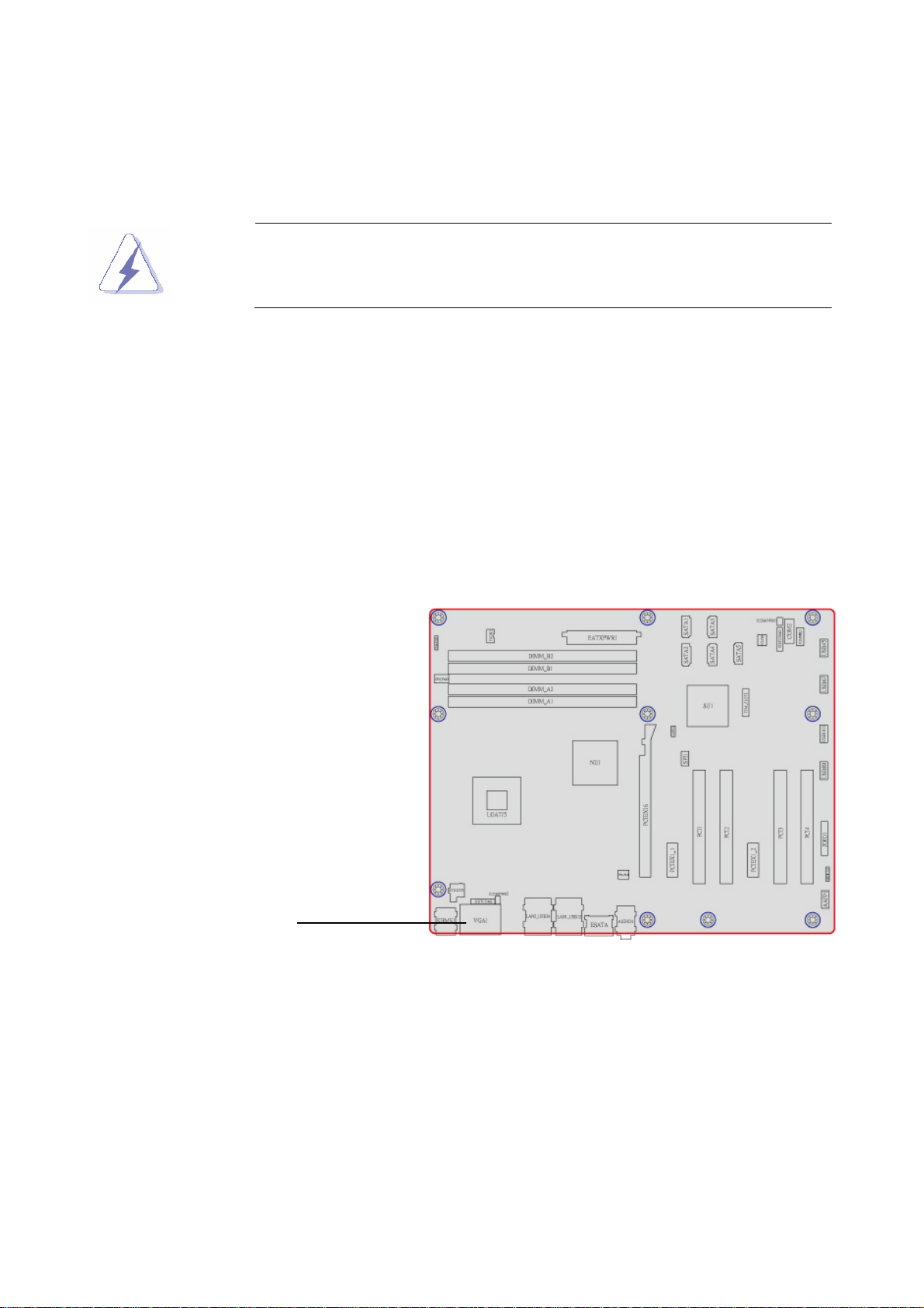
1.5.1 Placement Direction
When installing the motherboard, make sure that you place it into the chassis in the correct
orientation. The edge with external ports goes to the rear part of the chassis as indicated in
the image below.
1.5.2 Screw Holes
Place ten (10) screws into the holes indicated by circles to secure the motherboard to the
chassis.
Place this side towards
the rear of the chassis
AX45Q User’s Manual
15
Page 16

AX45Q
1.5.3 Motherboard Layout
16 AX45Q User’s Manual
Page 17
User’s Manual
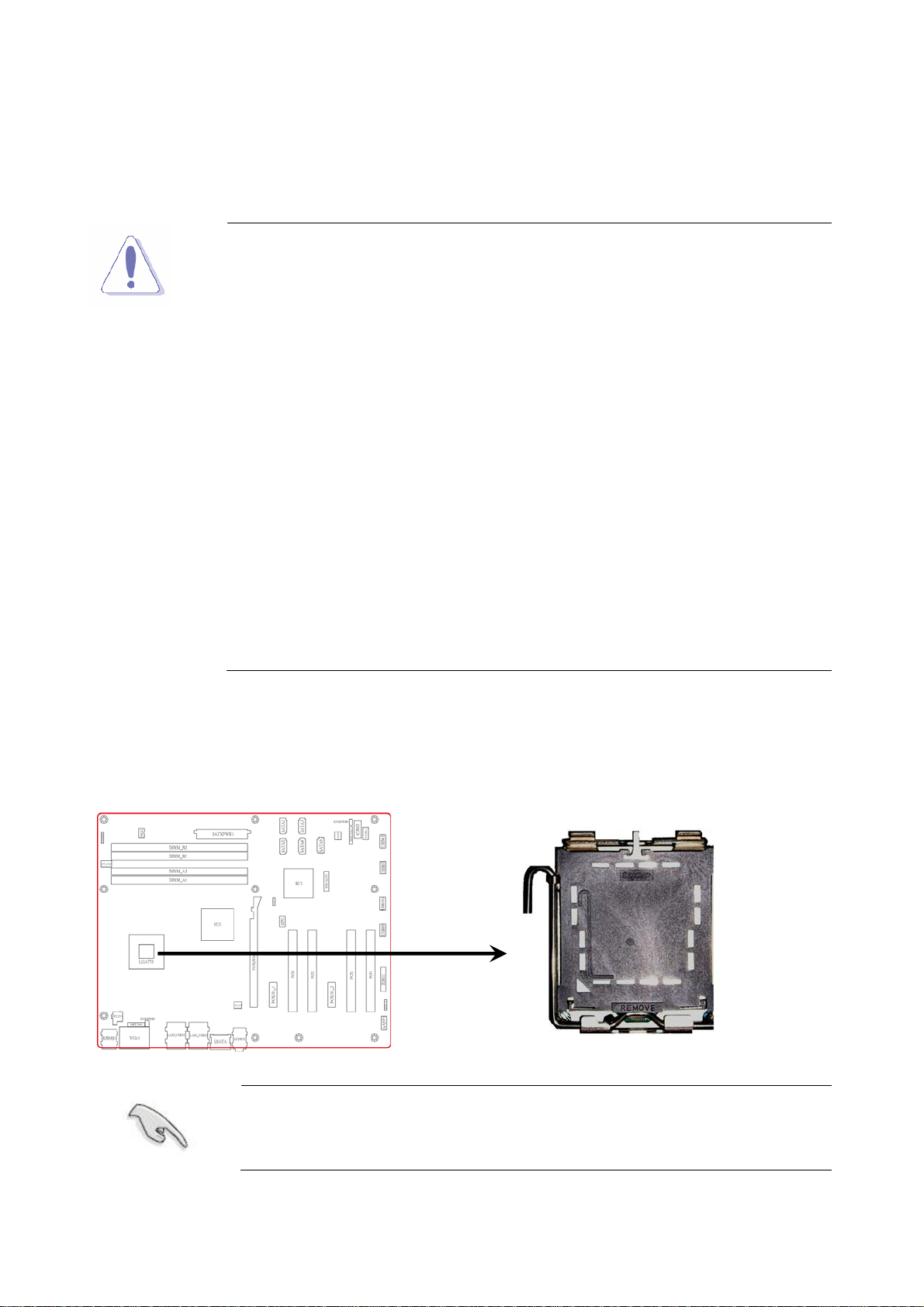
1.6 Central Processing Unit (CPU)
The motherboard comes with a surface mount LGA775 socket designed for the Intel®
Core™ 2 Quad/ Intel® Core™ 2 Duo processor in the 775-land package.
y Your boxed Intel® Core™ 2 Quad/ Intel® Core™ 2 Duo LGA775
processor package should come with installation instructions for
the CPU, fan and heatsink assembly. If the instructions in this
section do not match the CPU documentation, follow the latter.
y Upon purchase of the motherboard, make sure that the PnP cap is
on the socket and the socket pins are not bent. Contact your
retailer immediately if the PnP cap is missing, or if you see any
damage to the PnP cap/socket pins/motherboard components.
ADVANSUS will shoulder the cost of repair only if the damage is
shipment/transit-related.
y Keep the cap after installing the motherboard. ADVANSUS will
process Return Merchandise Authorization (RMA) requests only if
the motherboard comes with the cap on the LGA775 socket.
y The product warranty does not cover damage to the socket pins
resulting from incorrect CPU installation/removal, or
misplacement/loss/incorrect removal of the PnP cap.
1.6.1 Installing the CPU
1. Locate the CPU socket on the motherboard.
Before installing the CPU, make sure that the socket box is facing
towards you and the load lever is on your left.
AX45Q User’s Manual
17
Page 18
AX45Q
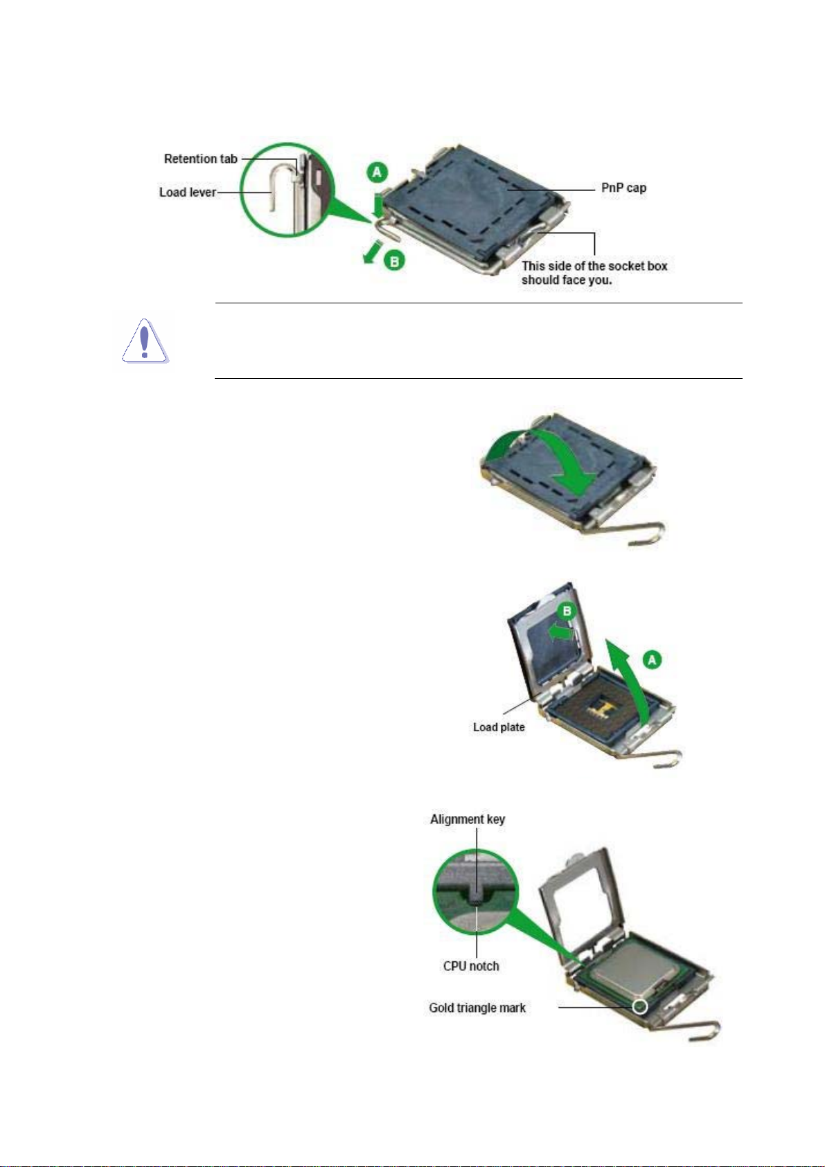
2. Press the load lever with your thumb (A), then move it to the left (B) until it is released
from the retention tab.
To prevent damage to the socket pins, do not remove the PnP cap
unless you are installing a CPU.
3. Lift the load lever in the direction of the
arrow to a 135º angle.
4. Lift the load plate with your thumb and
forefinger to a 100º angle (A), then
push the PnP cap from the load plate
window to remove (B).
5. Position the CPU over the socket,
making sure that the gold triangle is on
the bottom-left corner of the socket
then fit the socket alignment key into
the CPU notch.
18 AX45Q User’s Manual
Page 19

6. Close the load plate (A), then push the
load lever (B) until it snaps into the
retention tab.
The CPU fits in only one correct orientation. DO NOT force the CPU
into the socket to prevent bending the connectors on the socket and
User’s Manual
damaging the CPU!
The motherboard supports Intel® LGA775 processors with the Intel®
Enhanced Memory 64 Technology (EM64T), Enhanced Intel
SpeedStep® Technology (EIST), and Hyper-Threading Technology.
AX45Q User’s Manual
19
Page 20
AX45Q
1.6.2 Installing the CPU Heatsink and Fan
The Intel® Core™ 2 Quad/ Intel® Core™ 2 Duo LGA775 processor requires a specially
designed heatsink and fan assembly to ensure optimum thermal condition and
performance.
z Install the motherboard to the chassis before you install the CPU
fan and heatsink assembly.
z When you buy a boxed Intel® Core™ 2 Quad/ Intel® Core™ 2
Duo processor, the package includes the CPU fan and heatsink
assembly. If you buy a CPU separately, make sure that you use
only Intel®‑certified multi‑directional heatsink and fan.
z Your Intel® Core™ 2 Quad/ Intel® Core™ 2 Duo LGA775
heatsink and fan assembly comes in a push-pin design and
requires no tool to install.
If you purchased a separate CPU heatsink and fan assembly, make
sure that you have properly applied Thermal Interface Material to the
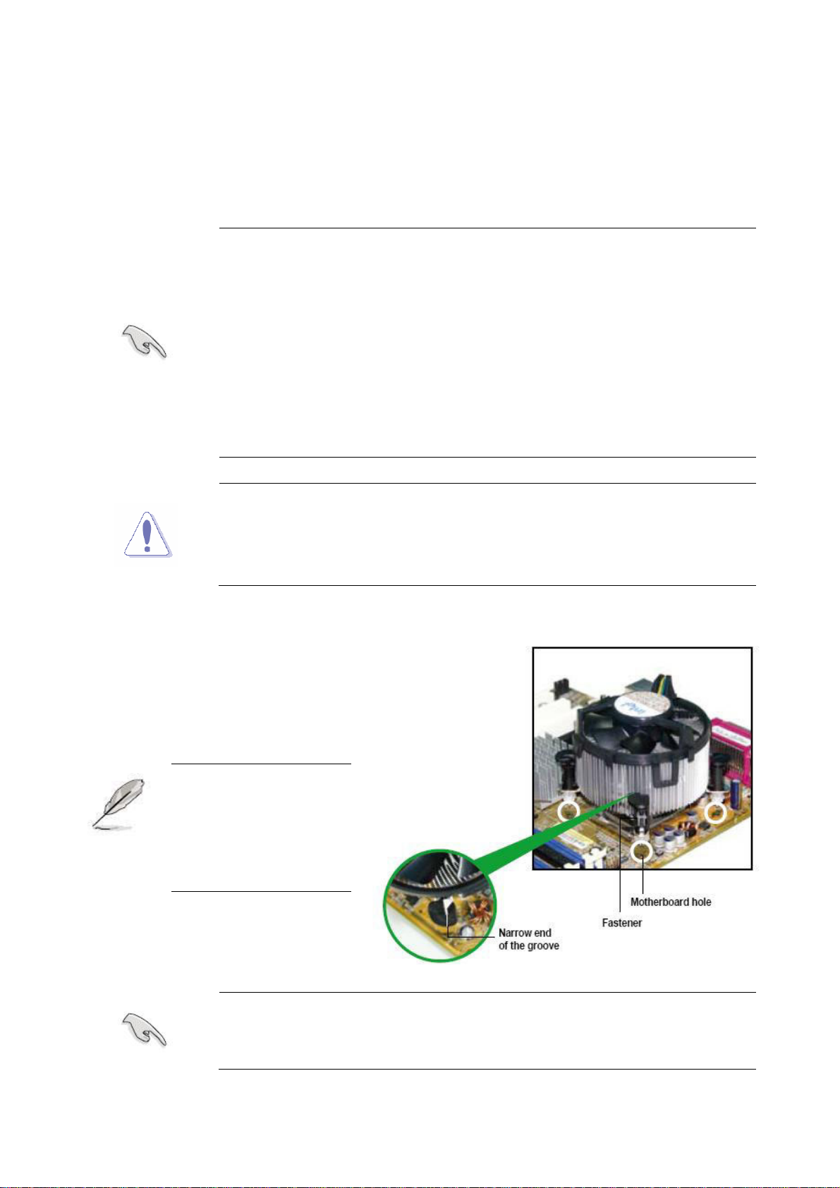
To install the CPU heatsink and fan:
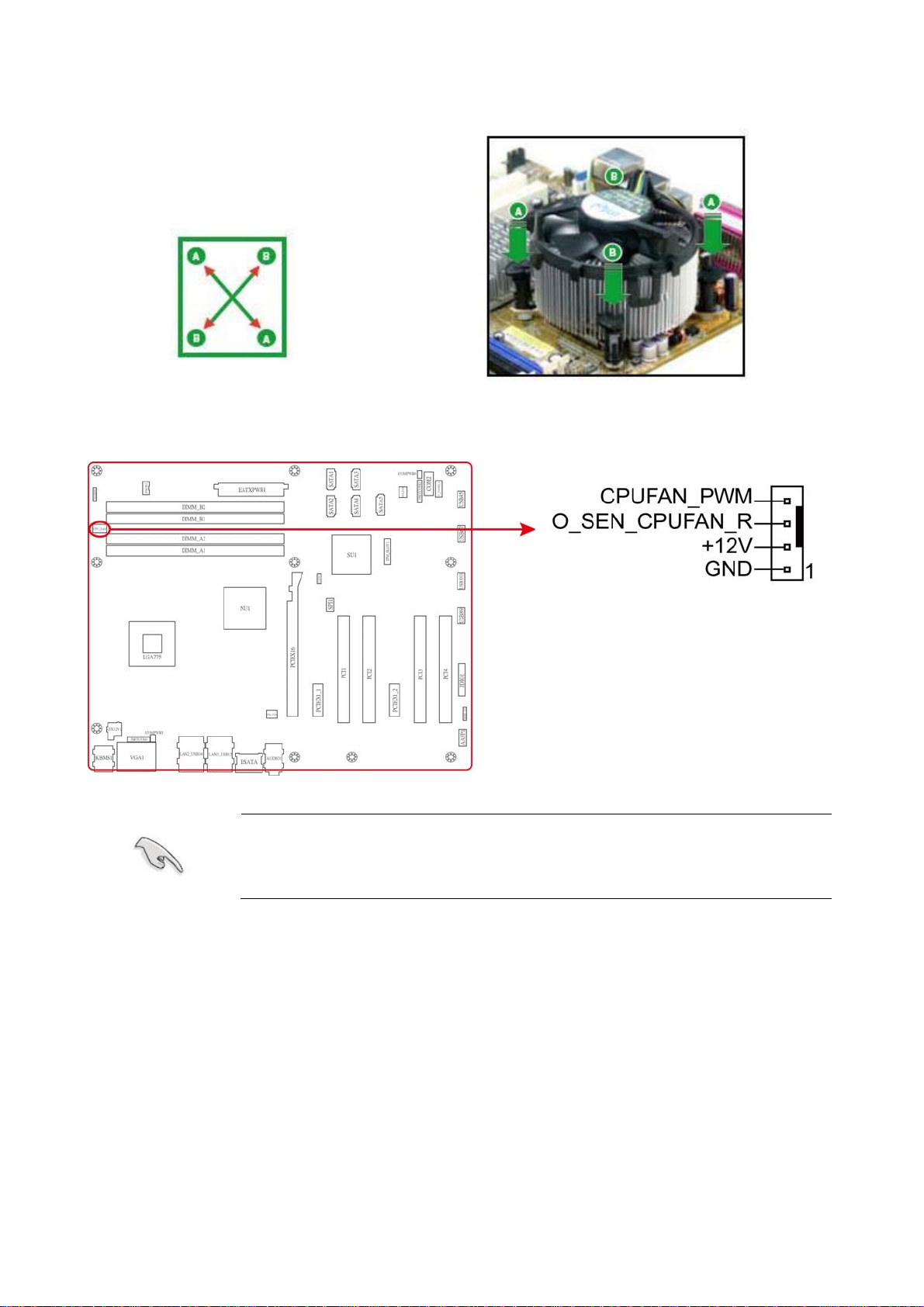
1. Place the heatsink on top of
the installed CPU, making
sure that the four fasteners
match the holes on the
motherboard.
Orient the heatsink
and fan assembly
such that the CPU fan
cable is closest to the
CPU fan connector.
CPU heatsink or CPU before you install the heatsink and fan
assembly.
Make sure each fastener is oriented as shown, with the narrow groove
20 AX45Q User’s Manual
directed outward.
Page 21
User’s Manual
2. Push down two fasteners at a
time in a diagonal sequence
to secure the heatsink and fan
assembly in place.
3. Connect the CPU fan cable to the connector on the motherboard labeled CPU_FAN.
Do not forget to connect the CPU fan connector! Hardware monitoring
errors can occur if you fail to plug this connector.
AX45Q User’s Manual
21
Page 22
AX45Q
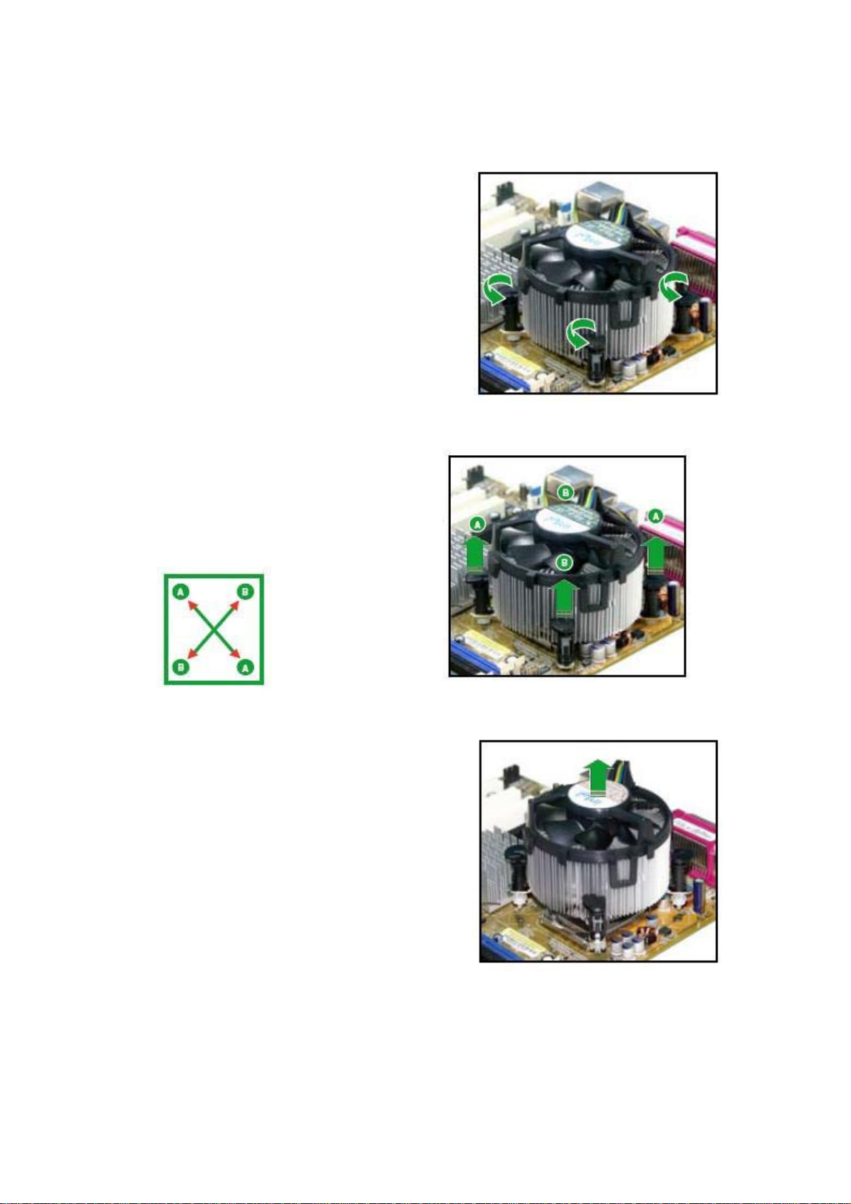
1.6.3 Uninstalling the CPU Heatsink and Fan
To uninstall the CPU heatsink and fan:
1. Disconnect the CPU fan cable from the
connector on the motherboard.
2. Rotate each fastener counterclockwise.
3. Pull up two fasteners at a time
in a diagonal sequence to
disengage the heatsink and
fan assembly from the
motherboard
4. Carefully remove the heatsink and fan
assembly from the motherboard.
22 AX45Q User’s Manual
Page 23
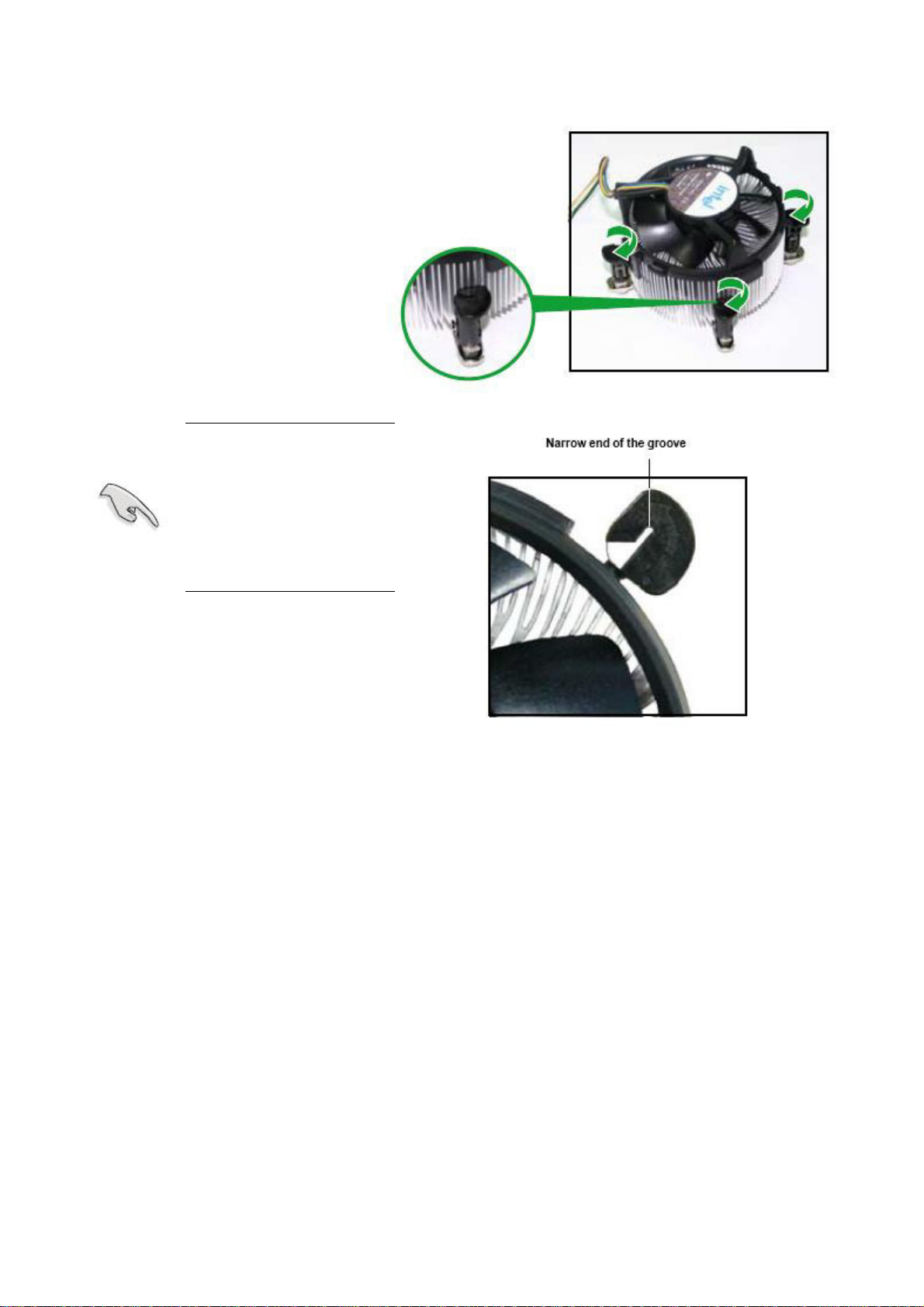
5. Rotate each fastener
clockwise to ensure correct
orientation when reinstalling.
The narrow end of the
groove should point
outward after
resetting. (The photo
shows the groove
User’s Manual
shaded for emphasis.)
AX45Q User’s Manual
23
Page 24
AX45Q
1.7 System memory
1.7.1 Overview
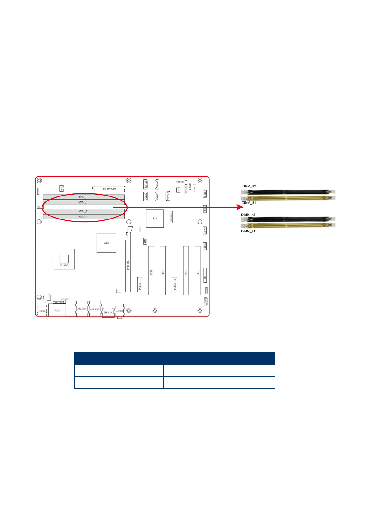
The motherboard comes with two 240-pin Double Data Rate 2 (DDR2) Dual Inline Memory
Modules (DIMM) sockets.
A DDR2 module has the same physical dimensions as a DDR DIMM but has a 240-pin
footprint compared to the 184-pin DDR DIMM. DDR2 DIMMs are notched differently to
prevent installation on a DDR DIMM socket. The following figure illustrates the location of
the sockets:
240-Pin DDR2 DIMM sockets
Channel Socket
Channel A DIMM_A1 and DIMM_A2
Channel B DIMM_B1 and DIMM_B2
24 AX45Q User’s Manual
Page 25

User’s Manual
1.7.2 Memory Configurations
You may install 64 MB, 128 MB, 256 MB, 512 MB and 1 GB unbuffered ECC or non-ECC
DDR DIMMs into the DIMM sockets using the memory configurations in this section.
y IF you installed four 1GB memory modules, the system may detect less
than 3GB of total memory because of address space allocation for other
critical functions. This limitation applies to Windows XP 32-bit version
operating system since it does not support PAE (Physical Address
Extension) mode.
y IF you install Windows XP 32-bit version operating system, we
recommend that you install less than 3GB of total memory.
y For dual-channel configuration, the total size of memory module(s)
installed per channel must be the same for better performance (DIMM_A1
+DIMM_A2=DIMM_B1+DIMM_B2).
y When using one DDR DIMM module, install into DIMM_B1 slot only.
y When using two DDR DIMM modules, install into DIMM_A1 and
DIMM_B1 slots only.
y Always install DIMMs with the same CAS latency. For optimum
compatibility, it is recommended that you obtain memory modules from
the same vendor. Refer to the memory Qualified Vendors List on the next
page for details.
y Due to CPU limitation, DIMM modules with 128 Mb memory chips or
double-sided x16 memory chips are not supported in this motherboard.
AX45Q User’s Manual
25
Page 26

AX45Q
1.7.3 Installing a DIMM
Make sure to unplug the power supply before adding or removing DIMMs
or other system components. Failure to do so may cause severe damage
1. Unlock a DIMM socket by pressing the
retaining clips outward
2. Align a DIMM on the socket such that the
notch on the DIMM matches the break on
the socket.
3. Firmly insert the DIMM into the socket
until the retaining clips snap back in place
and the DIMM is properly seated.
to both the motherboard and the components.
z A DDR2 DIMM is keyed with a notch so that it fits in only one
direction. DO NOT force a DIMM into a socket to avoid damaging the
DIMM.
z The DDR2 DIMM sockets do not support DDR DIMMs. DO NOT
install DDR DIMMs to the DDR2 DIMM socket.
26 AX45Q User’s Manual
Page 27

1.7.4 Removing a DIMM
1. Simultaneously press the retaining clips
outward to unlock the DIMM.
Support the DIMM lightly with your fingers when pressing the retaining
clips. The DIMM might get damaged when it flips out with extra force.
2. Remove the DIMM from the socket.
User’s Manual
AX45Q User’s Manual
27
Page 28

AX45Q
1.8 Expansion slots
In the future, you may need to install expansion cards. The following sub-sections describe
the slots and the expansion cards that they support.
Make sure to unplug the power cord before adding or removing
expansion cards. Failure to do so may cause you physical injury and
damage motherboard components.
1.8.1 Installing an Expansion Card
1. Before installing the expansion card, read the documentation that came with it and
make the necessary hardware settings for the card.
2. Remove the system unit cover (if your motherboard is already installed in a chassis).
3. Remove the bracket opposite the slot that you intend to use. Keep the screw for later
use.
4. Align the card connector with the slot and press firmly until the card is completely seated
on the slot.
5. Secure the card to the chassis with the screw you removed earlier.
6. Replace the system cover.
1.8.2 Configuring an Expansion Card
After installing the expansion card, configure it by adjusting the software settings.
1. Turn on the system and change the necessary BIOS settings, if any. See Chapter 2 for
information on BIOS setup.
2. Assign an IRQ to the card if needed. Refer to the tables on the next page.
3. Install the software drivers for the expansion card.
28 AX45Q User’s Manual
Page 29

1.8.3 PCI slots 1.8.4 PCI Express x16
User’s Manual
The PCI slots support cards such as a
LAN card, SCSI card, USB card, and
other cards that comply with PCI
specifications. The figure shows the
type of LAN card that can be installed
on a PCI slot.
This motherboard supports PCI Express x16
graphic cards that comply with the PCI Express
specifications. The figure shows a graphics
card installed on the PCI Express x16 slot.
1.8.5 PCI Express x1
This motherboard supports PCI
Express x1 network cards, SCSI cards
and other cards that comply with the
PCI Express specifications. The figure
shows the type of network card that can
be installed on the PCI Express x1 slot.
AX45Q User’s Manual
29
Page 30

AX45Q
1.9 Jumpers
1.9.1 Clear RTC RAM (CLRTC)
This jumper allows you to clear the Real Time Clock (RTC) RAM in CMOS. You can clear
the CMOS memory of date, time, and system setup parameters by erasing the CMOS RTC
RAM data. The onboard button cell battery powers the RAM data in CMOS, which include
system setup information such as system passwords.
To erase the RTC RAM:
1. Turn OFF the computer and unplug the power cord.
2. Remove the onboard battery.
3. Move the jumper cap from pins 1-2 (default) to pins 2-3. Keep the cap on pins 2-3 for
about 5~10 seconds, then move the cap back to pins 1-2.
4. Re-install the battery.
5. Plug the power cord and turn ON the computer.
6. Hold down the <Del> key during the boot process and enter BIOS setup to re-enter
data.
Except when clearing the RTC RAM, never remove the cap on CLRTC
jumper default position. Removing the cap will cause system boot failure!
You do not need to clear the RTC when the system hangs due to
overclocking. For system failure due to overclocking, use the C.P.R.
(CPU Parameter Recall) feature. Shut down and reboot the system so
the BIOS can automatically reset parameter settings to default values.
30 AX45Q User’s Manual
Page 31

User’s Manual
1.9.2 COM1/2 Voltage Select
This jumper allows you to select COM 1/2 Voltage power.
(JCOMPWR5, JCOMPWR6)
1.9.3 RS232/422/485 Select
This jumper allows you to select RS232/422/485.
(JSETCOM1, JSETCOM2)
AX45Q User’s Manual
31
Page 32

AX45Q
1.9.4 Intruder Select
This jumper allows you to select Intruder.
(CHASSIS1)
32 AX45Q User’s Manual
Page 33

1.10 Connectors
1.10.1 Rear panel connectors
User’s Manual
1. PS/2 mouse port (green). This port is for a PS/2 mouse.
2. Serial connector. This 9-pin COM1 port is for serial devices.
3 & 4. LAN (RJ-45) port. This port allows Gigabit connection to a Local Area Network (LAN)
through a network hub. Refer to the table below for the LAN port LED indications.
LAN port LED indications
ACT/ LINK LED SPEED LED
Status Description Status Description
OFF No link OFF 10Mbps connection
Orange Linked Orange 100Mbps connection
Blinking Data activity Green 1Gbps connection
5. Line In port (light blue). This port connects a tape, CD, DVD player, or other audio
sources.
6. Line Out port (lime). This port connects a headphone or a speaker. In 4-channel,
6-channel, and 8-channel configuration, the function of this port becomes Front Speaker
Out.
7. Microphone port (pink). This port connects a microphone.
8. eSATA port (red). This port connects a SATA HDD.
9. USB 2.0 ports 1 and 2. These two 4-pin Universal Serial Bus (USB) ports are available
for connecting USB 2.0 devices.
10. USB 2.0 ports 3 and 4. These two 4-pin Universal Serial Bus (USB) ports are available
for connecting USB 2.0 devices.
11. VGA port. This 15-pin VGA port connects to a VGA monitor.
AX45Q User’s Manual
33
Page 34

AX45Q
12. PS/2 keyboard port (purple). This port is for a PS/2 keyboard.
1.10.2 Internal connectors
1. Front panel audio connector (10-pin AAFP1)
This connector is for a chassis-mounted front panel audio I/O module that supports either
HD Audio or legacy AC’97 audio standard.
It is recommended that you connect a high-definition front panel audio
module to this connector to avail of the motherboard’s high‑definition
audio capability.
34 AX45Q User’s Manual
Page 35

User’s Manual
2. Serial Port connector (COM2)
This connector is for a serial (COM) port. Connect the serial port module cable to this
connector, then install the module to a slot opening at the back of the system chassis.
AX45Q User’s Manual
35
Page 36

AX45Q
3. Fan Connectors (3-pin SYS_FAN, 3-pin, 4-pin CPU_FAN, CHA_FAN)
The fan connectors support cooling fans of 350mA~740mA (8.88W max.) or a total of
1A~2.22A (26.64W max.) at +12V. Connect the fan cables to the fan connectors on the
motherboard, making sure that the black wire of each cable matches the ground pin of the
connector.
Do not forget to connect the fan cables to the fan connectors.
Insufficient air flow inside the system may damage the motherboard
components. These are not jumpers! DO NOT place jumper caps
on the fan connectors.
36 AX45Q User’s Manual
Page 37

User’s Manual
4. USB connector (10-1 pin USB45, USB67, USB89, USB1011)
This connector is for USB 2.0 ports. Connect the optional USB module cable to any of
these connectors, then install the module to a slot opening at the back of the system
chassis. This USB connector comply with USB 2.0 specification that supports up to 480
Mbps connection speed.
AX45Q User’s Manual
37
Page 38

AX45Q
5. ATX power connectors (20-pin EATXPWR, 4-pin ATX12V)
These connectors are for ATX power supply plugs. The power supply plugs are designed to
fit these connectors in only one orientation. Find the proper orientation and push down
firmly until the connectors completely fit.
y Do not forget to connect the 4-pin ATX +12 V power plug;
otherwise, the system will not boot.
y Use of a PSU with a higher power output is recommended when
configuring a system with more power-consuming devices. The
system may become unstable or may not boot up if the power is
inadequate.
y Make sure that your power supply unit (PSU) can provide at
least the minimum power required by your system. See the
table below for details.
38 AX45Q User’s Manual
Page 39

User’s Manual
6. Serial ATA connector (7-pin SATA1, SATA2, SATA3, SATA4, SATA5)
These connectors are for the Serial ATA signal cables for Serial ATA hard disk drives.
Install the Windows® 2000 Service Pack 4 or the Windows® XP Service
Pack1 or later before using Serial ATA.
7. System panel connector (10-1 pin F_PANEL1)
This connector supports several chassis-mounted functions.
The system panel connector is color-coded for easy connection. Refer to
the connector description below for details.
y Power/Soft-off button (Black 2-pin PWRSW)
This connector is for the system power button. Pressing the power button turns the system
AX45Q User’s Manual
39
Page 40

AX45Q
ON or puts the system in SLEEP or SOFT-OFF mode depending on the BIOS settings.
Pressing the power switch for more than four seconds while the system is ON turns the
system OFF.
y System Power LED connector (2-pin PWRLED)
This 2-pin connector is for the system power LED. The system power LED lights up when
you turn on the system power, and blinks when the system is in sleep mode.
y Reset button (Blue 2-pin RESET)
This 2-pin connector is for the chassis-mounted reset button for system reboot without
turning off the system power.
y Hard disk drive activity (Red 2-pin IDELED)
This 2-pin connector is for the HDD Activity LED. Connect the HDD Activity LED cable to
this connector. The IDE LED lights up or flashes when data is read from or written to the
HDD.
8. Digital Audio connector (4-pin SPDIF_OUT)
This connector is for the S/PDIF audio module to allow digital sound output.
Connect one end of the S/PDIF audio cable to this connector and the other end to the
S/PDIF module.
The S/PDIF out module is purchased separately.
40 AX45Q User’s Manual
Page 41

User’s Manual
9. SPI Connector (7-pin SPI1)
It is a point-to-point interface standard, allows network equipment designers to develop an
array of next-generation multi-service switches and routers to support multi-service traffic
with aggregate bandwidths up to OC-192 (10 Gb/s) and beyond, enabling them to
dramatically increase system performance.
10. Digital IO Connector (12-pin JDIO)
AX45Q User’s Manual
41
Page 42

AX45Q
2
This chapter tells how to change the
system settings through the BIOS
Setup menus. Detailed descriptions
of the BIOS parameters are also
provided.
42 AX45Q User’s Manual
BIOS Setup
Page 43

2.1 Managing and updating your BIOS
2.1.1 Creating a bootable floppy disk
1. Do either one of the following to create a bootable floppy disk.
DOS environment
a. Insert a 1.44MB floppy disk into the drive.
b. At the DOS prompt, type format A:/S then press <Enter>.
Windows® XP environment
a. Insert a 1.44 MB floppy disk to the floppy disk drive.
b. Click Start from the Windows® desktop, then select My Computer.
c. Select the 3 1/2 Floppy Drive icon.
d. Click File from the menu, then select Format. A Format 3 1/2 Floppy Disk
window appears.
e. Select Create an MS-DOS startup disk from the format options field, then click
User’s Manual
Start.
Windows® 2000 environment
To create a set of boot disks for Windows® 2000:
a. Insert a formatted, high density 1.44 MB floppy disk into the drive.
b. Insert the Windows® 2000 CD to the optical drive.
c. Click Start, then select Run. d. From the Open field, type
D:\bootdisk\makeboot a: assuming that D: is your optical drive.
d. Press <Enter>, then follow screen instructions to continue.
2. Copy the original or the latest motherboard BIOS file to the bootable floppy disk.
AX45Q User’s Manual
43
Page 44

AX45Q
2.2 BIOS setup program
The main BIOS setup menu is the first screen that you can navigate. Each main BIOS
setup menu option is described in this user’s guide.
The Main BIOS setup menu screen has two main frames. The left frame displays all the
options that can be configured. “Grayed-out” options cannot be configured. Options is blue
can be.
The right frame displays the key legend. Above the key legend is an area reserved for a
text message. When an option is selected in the left frame, it is highlighted in white.
Often a text message will accompany it.
z The default BIOS settings for this motherboard apply for most
conditions to ensure optimum performance. If the system
becomes unstable after changing any BIOS settings, load the
default settings to ensure system compatibility and stability.
Select the Load Default Settings item under the Exit Menu.
See section “2.9 Exit Menu.”
z The BIOS setup screens shown in this section are for reference
purposes only, and may not exactly match what you see on
your screen.
z Visit the Advansus website to download the latest BIOS file for
this motherboard.
2.2.1 Legend Box
The BIOS setup/utility uses a key-based navigation system called hot keys. Most of the
BIOS setup utility hot keys can be used at any time during the setup navigation process.
These keys include <F1>, <F10>, <Enter>, <ESC>, <Arrow> keys, and so on.
The keys in the legend bar allow you to navigate through the various setup menus.
Key(s) Function Description
I, J Left/Right The Left and Right <Arrow> keys allow you to select an setup screen.
For example: Main screen, Advanced screen, Chipset screen, and so
on.
K, L Up/Down The Up and Down <Arrow> keys allow you to select an setup item or
sub-screen.
+, - Plus/Minus The Plus and Minus <Arrow> keys allow you to change the field value
of a particular setup item.
For example: Date and Time.
44 AX45Q User’s Manual
Page 45

User’s Manual
Tab The <Tab> key allows you to select setup fields.
F1 The <F1> key allows you to display the General Help screen.
Press the <F1> key to open the General Help screen.
F10 The <F10> key allows you to save any changes you have made and
exit Setup. Press the <F10> key to save your changes.
ESC The <Esc> key allows you to discard any changes you have made
and exit the Setup. Press the <Esc> key to exit the setup without
saving your changes.
Enter The <Enter> key allows you to display or change the setup option
listed for a particular setup item. The <Enter> key can also allow you
to display the setup sub- screens.
2.2.2 List Box
This box appears only in the opening screen. The box displays an initial list of configurable
items in the menu you selected.
2.2.3 Sub-menu
Note that a right pointer symbol (X) appears to the left of certain fields. This pointer
indicates that you can display a sub-menu from this field. A sub-menu contains additional
options for a field parameter. To display a sub-menu, move the highlight to the field and
press <Enter>. The sub-menu appears. Use the legend keys to enter values and move
from field to field within a sub-menu as you would within a menu. Use the <Esc> key to
return to the main menu.
Take some time to familiarize yourself with the legend keys and their corresponding
functions. Practice navigating through the various menus and submenus. While moving
around through the Setup program, note that explanations appear in the Item Specific Help
window located to the right of each menu. This window displays the help text for the
currently highlighted field.
AX45Q User’s Manual
45
Page 46

AX45Q
2.3 Main Setup
When you first enter the Setup Utility, you will enter the Main setup screen. You can always
return to the Main setup screen by selecting the Main tab. There are two Main Setup
options. They are described in this section. The Main BIOS Setup screen is shown below.
y System Time/System Date
Use this option to change the system time and date. Highlight System Time or System
Date using the <Arrow> keys. Enter new values through the keyboard. Press the <Tab>
key or the <Arrow> keys to move between fields. The date must be entered in MM/DD/YY
format. The time is entered in HH:MM:SS format.
Note: The time is in 24-hour format. For example, 5:30 A.M. appears as 05:30:00, and
5:30P.M. as 17:30:00.
46 AX45Q User’s Manual
Page 47

User’s Manual
2.4 Advanced BIOS Setup
Select the Advanced tab from the setup screen to enter the Advanced BIOS Setup screen.
You can select any of the items in the left frame of the screen, such as SuperIO
Configuration, to go to the sub menu for that item. You can display an Advanced BIOS
Setup option by highlighting it using the <Arrow> keys. All Advanced BIOS Setup options
are described in this section. The Advanced BIOS Setup screen is shown below.
The sub menus are described on the following pages.
AX45Q User’s Manual
47
Page 48

AX45Q
2.4.1 CPU Configuration Setting
You can use this screen to select options for the CPU Configuration Settings. Use the up
and down <Arrow> keys to select an item. Use the <Plus> and <Minus> keys to change the
value of the selected option. A description of the selected item appears on the right side of
the screen. The settings are described on the following pages.
y Max CPUID Value Limit
The choices of Max CPUID Value Limit are Disabled, and Enabled.
y Intel® Virtualization Tech
The choices of Intel® Virtualization Tech are Enabled, Disabled.
y Execute-Disable Bit Capability
The choices of Execute-Disable Bit Capability are Enabled, Disabled.
48 AX45Q User’s Manual
Page 49

y Core Multi-Processing
The item is to enable or disable the Core Multi-processing function.
y Intel® SpeedStep™ tech
The choices of Execute-Disable Bit Capability are Enabled, Disabled.
User’s Manual
AX45Q User’s Manual
49
Page 50

AX45Q
2.4.2 IDE Configuration Setting
You can use this screen to select options for the IDE Configuration Settings. Use the up
and down <Arrow> keys to select an item. Use the <Plus> and <Minus> keys to change the
value of the selected option. A description of the selected item appears on the right side of
the screen. The settings are described on the following pages.
y Mirrored IDER Configuration
The choices of Mirrored IDER configuration are Disabled, and Enabled.
y SATA Configuration
The choices of SATA configuration are Disabled, Compatible, and Enhanced.
y Configure SATA as
This item allows to configure SATA as IDE, RAID, or AHCI.
50 AX45Q User’s Manual
Page 51

User’s Manual
y Primary/Secondary IDE Master/Slave, Third/Fourth IDE Master
Select one of the hard disk drives to configure it. Press <Enter> to access its the sub
menu. The options on the sub menu are described in the following sections.
y IDE Detect Time Out (Sec)
Set this option to stop the AMIBIOS from searching for IDE devices within the specified
number of seconds. Basically, this allows you to fine-tune the settings to allow for faster
boot times. Adjust this setting until a suitable timing that can detect all IDE disk drives
attached is found.
The default setting is 35.
Option Description
0 This value is the best setting to use if the onboard IDE controllers are set to a
specific IDE disk drive in the AMIBIOS.
5 Set this value to stop the AMIBIOS from searching the IDE bus for IDE disk
drives in five seconds. A large majority of ultra ATA hard disk drives can be
detected well within five seconds.
10 Set this value to stop the AMIBIOS from searching the IDE bus for IDE disk
drives in 10 seconds.
15 Set this value to stop the AMIBIOS from searching the IDE bus for IDE disk
drives in 15 seconds.
20 Set this value to stop the AMIBIOS from searching the IDE bus for IDE disk
drives in 20 seconds.
25 Set this value to stop the AMIBIOS from searching the IDE bus for IDE disk
drives in 25 seconds.
30 Set this value to stop the AMIBIOS from searching the IDE bus for IDE disk
drives in 30 seconds.
35 35 is the default value. It is the recommended setting when all IDE connectors
are set to AUTO in the AMIBIOS setting.
Note: Different IDE disk drives take longer for the BIOS to locate than others do.
AX45Q User’s Manual
51
Page 52

AX45Q
y AHCI Configuration
- AHCI BIOS Support
Enables for supporting AHCI BIOS. The choices are Enabled or Disabled.
- AHCI CD/DVD Boot Time Out
Select the time out value for detecting AHCI CD/DVD device(s).
52 AX45Q User’s Manual
Page 53

User’s Manual
2.4.3 SuperIO Configuration
You can use this screen to select options for the Super I/O settings. Use the up and down
<Arrow> keys to select an item. Use the <Plus> and <Minus> keys to change the value of
the selected option. The settings are described on the following pages. The screen is
shown below.
y Serial Port1 Address
This option specifies the base I/O port address and Interrupt Request address of serial port
1. The Optimal setting is 3F8/IRQ4.
Option Description
Disabled Set this value to prevent the serial port from accessing any system resources.
When this option is set to Disabled, the serial port physically becomes
unavailable.
3F8/IRQ4 Set this value to allow the serial port to use 3F8 as its I/O port address and
IRQ4 for the interrupt address. This is the default setting. The majority of serial
AX45Q User’s Manual
53
Page 54

AX45Q
port 1 or COM1 ports on computer systems use IRQ4 and I/O Port 3F8 as the
standard setting. The most common serial device connected to this port is a
mouse. If the system will not use a serial device, it is best to set this port to
Disabled.
y Serial Port2 Address
This option specifies the base I/O port address and Interrupt Request address of serial port
2. The Optimal setting is 2F8/IRQ3.
Option Description
Disabled Set this value to prevent the serial port from accessing any system resources.
When this option is set to Disabled, the serial port physically becomes
unavailable.
2F8/IRQ3 Set this value to allow the serial port to use 2F8 as its I/O port address and IRQ
3 for the interrupt address. This is the default setting. The majority of serial port
2 or COM2 ports on computer systems use IRQ3 and I/O Port 2F8 as the
standard setting. The most common serial device connected to this port is an
external modem. If the system will not use an external modem, set this port to
Disabled.
Note: Most internal modems require the use of the second COM port and use
3F8 as its I/O port address and IRQ 4 for its interrupt address. This requires
that the Serial Port2 Address be set to Disabled or another base I/O port
address and Interrupt Request address.
2.4.4 Hardware Health Configuration
You can use this screen to select options for the Hardware Health settings. Use the up and
down <Arrow> keys to select an item. Use the <Plus> and <Minus> keys to change the
value of the selected option. The settings are described on the following pages. The screen
is shown below.
54 AX45Q User’s Manual
Page 55

User’s Manual
y Chassis Intrusion
This item selects the chassis intrusion. The choices are Disabled or Enabled.
y System Temperature
This shows you the current temperature of system.
y CPU Temperature
This shows you the current CPU temperature.
y CPU_FAN Speed
This shows the current CPU FAN operating speed.
y SYS_FAN Speed
This shows the current System FAN operating speed.
y CHA_FAN Speed
This shows the current Chassis FAN operating speed.
y Vcore/ 3VCC/ +12V/ +5V/ 5VSB/ 3VSB/ VBAT
This shows the voltage of VCORE, 3VCC, +12V, +5V, 5VSB(V), 3VSB(V) and VBAT(V).
AX45Q User’s Manual
55
Page 56

AX45Q
2.4.5 ACPI Configuration
You can use this screen to select options for the ACPI settings. Use the up and down
<Arrow> keys to select an item. Use the <Plus> and <Minus> keys to change the value of
the selected option. The settings are described on the following pages. The screen is
shown below.
56 AX45Q User’s Manual
Page 57

y Chipset ACPI Configuration
This item allows you to set South Bridge ACPI Configuration.
User’s Manual
- High Performance Event Timer
This item allows you to enable or disable the High Performance Event Timer.
AX45Q User’s Manual
57
Page 58

AX45Q
2.4.6 APM Configuration
You can use this screen to select options for the APM settings. Use the up and down
<Arrow> keys to select an item. Use the <Plus> and <Minus> keys to change the value of
the selected option. The settings are described on the following pages. The screen is
shown below.
y Power Management/APM
This item allows you to set APM to Enabled or Disabled.
y Restore on AC Power Loss
This item allows you to set AC Power Loss to Power Off, Power On, or Last State.
y Throttle Slow Clock Ratio
Select the Duty Cycle in Throttle mode. The choices are 87.5%, 75.8%, 6.5%, 50%, 37.5%,
25% and 12.5%.
y Resume On Ring
Disable or Enable RI to generate a wake event.
58 AX45Q User’s Manual
Page 59

User’s Manual
y Resume On PME#
Disable or Enable PME to generate a wake event.
y Resume On PCIE WAKE#
Disable or Enable PCIE generate a wake event.
y Resume RTC Alarm
Disable or Enable RTC to generate a wake event.
2.4.7 Intel Danbury (DT) Configuration
You can use this screen to select options for the Intel Danbury (DT) settings. Use the up
and down <Arrow> keys to select an item. Use the <Plus> and <Minus> keys to change the
value of the selected option. The settings are described on the following pages. The screen
is shown below.
y DTAM Support
The Choices are enabled or disabled the DTAM support.
AX45Q User’s Manual
59
Page 60
AX45Q
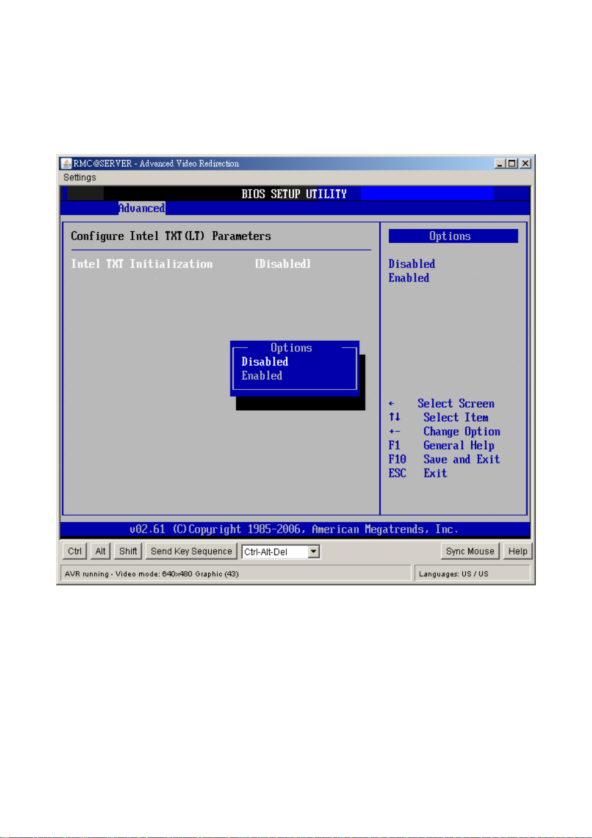
2.4.8 Intel TXT (LT) Configuration
You can use this screen to select options for the Intel TXT (LT) settings. Use the up and
down <Arrow> keys to select an item. Use the <Plus> and <Minus> keys to change the
value of the selected option. The settings are described on the following pages. The screen
is shown below.
y Intel TXT Initialization
The Choices are enabled or disabled the Intel TXT initialization.
60 AX45Q User’s Manual
Page 61

User’s Manual
2.4.9 Intel VT-d Configuration
You can use this screen to select options for the Intel VT-d settings. Use the up and down
<Arrow> keys to select an item. Use the <Plus> and <Minus> keys to change the value of
the selected option. The settings are described on the following pages. The screen is
shown below.
y Intel VT-d
The Choices are enabled or disabled the Intel VT-d.
AX45Q User’s Manual
61
Page 62

AX45Q
2.4.10 Trusted Computing
You can use this screen to select options for the Intel Trusted Computing settings. Use the
up and down <Arrow> keys to select an item. Use the <Plus> and <Minus> keys to change
the value of the selected option. The settings are described on the following pages. The
screen is shown below.
y TCG/TPM SUPPORT
Enable or disable TPM TCG (TPM 1.1/1.2) support in BIOS.
y Execute TPM Command
The choices are “Don’t Change” / “Disabled” / “Enabled”.
62 AX45Q User’s Manual
Page 63

User’s Manual
2.5 Advanced PCI/PnP Settings
Select the PCI/PnP tab from the setup screen to enter the Plug and Play BIOS Setup
screen. You can display a Plug and Play BIOS Setup option by highlighting it using the
<Arrow> keys. All Plug and Play BIOS Setup options are described in this section. The Plug
and Play BIOS Setup screen is shown below.
2.5.1 Clear NVRAM
This item is to clear NVRAM during system boot. The choices are No or Yes.
2.5.2 Plug & Play O/S
Set this value to allow the system to modify the settings for Plug and Play operating system
support. The default setting is No.
Option Description
No The No setting is for operating systems that do not meet the Plug and Play
AX45Q User’s Manual
63
Page 64

AX45Q
specifications. It allows the BIOS to configure all the devices in the system. This
is the default setting.
Yes The Yes setting allows the operating system to change the interrupt, I/O and
DMA settings. Set this option if the system is running Plug and Play aware
operating systems.
2.5.3 PCI Latency Timer
Set this value to allow the PCI Latency Timer to be adjusted. This option sets the latency of
all PCI devices on the PCI bus. The default setting is 64.
Option Description
32 This option sets the PCI latency to 32 PCI clock cycles.
64 This option sets the PCI latency to 64 PCI clock cycles. This is the default
setting.
96 This option sets the PCI latency to 96 PCI clock cycles.
128 This option sets the PCI latency to 128 PCI clock cycles.
160 This option sets the PCI latency to 160 PCI clock cycles.
192 This option sets the PCI latency to 192 PCI clock cycles.
224 This option sets the PCI latency to 224 PCI clock cycles.
248 This option sets the PCI latency to 248 PCI clock cycles.
2.5.4 Allocate IRQ to PCI VGA
Set this value to allow or restrict the system from giving the VGA adapter card an interrupt
address. The default setting is Yes.
Option Description
Yes Set this value to allow the allocation of an IRQ to a VGA adapter card that uses
the PCI local bus. This is the default setting.
No Set this value to prevent the allocation of an IRQ to a VGA adapter card that
uses the PCI local bus.
2.5.5 Palette Snooping
Set this value to allow the system to modify the Palette Snooping settings. The default
setting is Disabled.
Option Description
Disabled This is the default setting and should not be changed unless the VGA card
manufacturer requires Palette Snooping to be Enabled.
Enabled This setting informs the PCI devices that an ISA based Graphics device is
installed in the system. It does this so the ISA based Graphics card will function
correctly. This does not necessarily indicate a physical ISA adapter card. The
graphics chipset can be mounted on a PCI card. Always check with your adapter
64 AX45Q User’s Manual
Page 65

User’s Manual
card’s manual first, before modifying the default settings in the BIOS.
2.5.6 PCI IDE BusMaster
Set this value to allow or prevent the use of PCI IDE busmastering. The setting is Disabled.
Option Description
Disabled Set this value to prevent PCI busmastering. This is the default setting.
Enabled This option specifies that the IDE controller on the PCI local bus has mastering
capabilities.
2.5.7 OffBoard PCI/ISA IDE Card
Set this value to allow the OffBoard PCI/ISA IDE Card to be selected. The default setting is
Auto.
Option Description
Auto This setting will auto select the location of an OffBoard PCI IDE adapter card.
This is the default setting.
PCI Slot 1 This setting will select PCI Slot 1 as the location of the OffBoard PCI IDE
adapter card. Use this setting only if there is an IDE adapter card installed in
PCI Slot 1.
PCI Slot 2 This setting will select PCI Slot 2 as the location of the OffBoard PCI IDE
adapter card. Use this setting only if there is an IDE adapter card installed in
PCI Slot 2.
PCI Slot 3 This setting will select PCI Slot 3 as the location of the OffBoard PCI IDE
adapter card. Use this setting only if there is an IDE adapter card installed in
PCI Slot 3. This option is available even if the motherboard does not have a
PCI Slot 3. If the motherboard does not have a PCI Slot 3, do not use this
setting.
PCI Slot 4 This setting will select PCI Slot 4 as the location of the OffBoard PCI IDE
adapter card. Use this setting only if there is an IDE adapter card installed in
PCI Slot 4. This option is available even if the motherboard does not have a
PCI Slot 4. If the motherboard does not have a PCI Slot 4, do not use this
setting.
PCI Slot 5 This setting will select PCI Slot 5 as the location of the OffBoard PCI IDE
adapter card. Use this setting only if there is an IDE adapter card installed in
PCI Slot 5. This option is available even if the motherboard does not have a
PCI Slot 5. If the motherboard does not have a PCI Slot 5, do not use this
setting.
PCI Slot 6 This setting will select PCI Slot 6 as the location of the OffBoard PCI IDE
adapter card. Use this setting only if there is an IDE adapter card installed in
PCI Slot 6. This option is available even if the motherboard does not have a
PCI Slot 6. If the motherboard does not have a PCI Slot 6, do not use this
AX45Q User’s Manual
65
Page 66

AX45Q
setting.
2.5.8 IRQ
Set this value to allow the IRQ settings to be modified. The default setting is available.
Interrupt Option Description
IRQ3
IRQ4
IRQ5
IRQ7
IRQ9
IRQ10
IRQ11
IRQ14
IRQ15
2.5.9 DMA
Set this value to allow the DMA setting to be modified. The default setting is Available.
DMA Channel Option Description
DMA Channel 0
DMA Channel 1
DMA Channel 3
DMA Channel 5
Available This setting allows the specified IRQ to be used by a PCI/PnP
device. This is the default setting.
Reserved This setting allows the specified IRQ to be used by a legacy ISA
device.
Available This setting allows the specified DMA to be used by PCI/PnP
device. This is the default setting.
DMA Channel 6
DMA Channel 7
Reserved This setting allows the specified DMA to be used by a legacy
ISA device.
66 AX45Q User’s Manual
Page 67

User’s Manual
2.6 Boot Setting Configuration
Select the Boot tab from the setup screen to enter the Boot Setup screen. You can display
a Boot Setup option by highlighting it using the <Arrow> keys. All Boot BIOS Setup options
are described in this section. The Boot BIOS Setup screen is shown below.
AX45Q User’s Manual
67
Page 68

AX45Q
2.6.1 Boot Settings Configuration
You can use this screen to select options for the Boot settings. Use the up and down
<Arrow> keys to select an item. Use the <Plus> and <Minus> keys to change the value of
the selected option. The settings are described on the following pages. The screen is
shown below.
y Quick Boot
The default setting is Enabled.
Option Description
Disabled Set this value to allow the BIOS to perform all POST tests.
Enabled Set this value to allow the BIOS to skip certain POST tests to boot faster.
y Quiet Boot
Set this value to allow the boot up screen options to be modified between POST messages
or OEM logo. The default setting is Disabled.
68 AX45Q User’s Manual
Page 69

User’s Manual
Option Description
Disabled Set this value to allow the computer system to display the POST messages.
Enabled Set this value to allow the computer system to display the OEM logo. This is the
default setting.
y Bootup Num-Lock
Set this value to allow the Number Lock setting to be modified during boot up. The default
setting is On.
Option Description
Off This option does not enable the keyboard Number Lock automatically. To use
the 10-keys on the keyboard, press the Number Lock key located on the upper
left-hand corner of the 10-key pad. The Number Lock LED on the keyboard will
light up when the Number Lock is engaged.
On Set this value to allow the Number Lock on the keyboard to be enabled
automatically when the computer system is boot up. This allows the immediate
use of 10-keys numeric keypad located on the right side of the keyboard. To
confirm this, the Number Lock LED light on the keyboard will be lit. This is the
default setting.
y Wait For “F1” If Error
Set this value to allow the Wait for “F1” Error setting to be modified. The default setting is
Enabled.
Option Description
Disabled This prevents the to wait on an error for user intervention. This setting should be
used if there is a known reason for a BIOS error to appear. An example would
be a system administrator must remote boot the system. The computer system
does not have a keyboard currently attached. If this setting is set, the system will
continue to boot up in to the operating system. If “F1” is enabled, the system will
wait until the BIOS setup is entered.
Enabled Set this value to allow the system BIOS to wait for any error. If an error is
detected, pressing <F1> will enter Setup and the BIOS setting can be adjusted
to fix the problem. This normally happens when upgrading the hardware and not
setting the BIOS to recognized it. This is the default setting.
y Hit “DEL” Message Display
Set this value to allow the Hit “DEL” to enter Setup Message Display to be modified. The
default setting is Enabled.
Option Description
Disabled This prevents the to display
Hit Del to Enter Setup
AX45Q User’s Manual
69
Page 70

AX45Q
during memory initialization. If Quiet Boot is enabled, the Hit “DEL” message will
not display.
Enabled This allows the to display
Hit Del to Enter Setup
during memory initialization. This is the default setting.
2.6.2 Boot Device Priority
Use this screen to specify the order in which the system checks for the device to boot from.
To access this screen, select Boot Device Priority on the Boot Setup screen and press
<Enter>. The following screen displays:
y 1st Boot Device
Set the boot device options to determine the sequence in which the computer checks whick
device to boot from. The settings are Removable Dev., Hard Drive, or ATAPI CDROM.
70 AX45Q User’s Manual
Page 71

User’s Manual
2.6.3 Hard Disk Drives
Use this screen to view the hard disk drives in the system. To access this screen, select
Hard disk drives on the Boot Setup screen and press <Enter>. The following screen
displays examples of hard disk drives:
y 1st Drive
This item specifies the boot sequence from the available device.
AX45Q User’s Manual
71
Page 72

AX45Q
2.7 Security Setup
Select Security Setup from the Setup main BIOS setup menu. All Security Setup options,
such as password protection and virus protection, are described in this section. To access
the sub menu for the following items, select the item and press <Enter>:
y Change Supervisor Password
The Security Setup screen is shown below. The sub menus are documented on the
following pages.
2.7.1 Change Supervisor Password
This item indicates whether a supervisor password has been set. If the password has been
installed, Installed displays. If not, Not Installed displays.
72 AX45Q User’s Manual
Page 73

User’s Manual
2.8 Chipset Setup
Select the Chipset tab from the setup screen to enter the Chipset BIOS Setup screen. You
can select any of the items in the left frame of the screen, such as CPU Configuration, to go
to the sub menu for that item. You can display a Chipset BIOS Setup option by highlighting
it using the <Arrow> keys. All Chipset BIOS Setup options are described in this section.
The Chipset BIOS Setup screen is shown below.
AX45Q User’s Manual
73
Page 74

AX45Q
2.8.1 North Bridge Configuration
You can use this screen to select options for the North Bridge Configuration. Use the up
and down <Arrow> keys to select an item. Use the <Plus> and <Minus> keys to change the
value of the selected option.
Note: The North Bridge Configuration setup screen varies depending on the supported
North Bridge chipset.
y Memory Remap Feature
Set this value to allow the Memory Remap Feature to be modified. The default setting is
Enabled.
Option Description
Disabled Do not allow remapping of memory.
Enabled Allow remapping of overlapping PCI memory above the total physical memory.
74 AX45Q User’s Manual
Page 75

User’s Manual
y Initate Graphic Adapter
This item selects which graphics controller to use as the primary boot device. The options
are IGD, PCI/IGD, PCI/PEG, PEG/IGD, PEG/PCI. The default setting is PEG/PCI.
y IGD Graphics Mode Select
This item selects the amount of system memory used by the internal graphics device. The
choices are Disabled, Enabled 32MB, Enabled 64MB, and Enabled 128MB.
y PEG Port
The choices are Auto or Disabled.
y Video Function Configuration
- DVMT Mode Select
Use this field to select the memory to allocate for video memory. The choice is
“DVMT”.
AX45Q User’s Manual
75
Page 76

AX45Q
- DVMT/Fixed Memory Size
Specify the size of DVMT/system memory to allocate for video memory.
2.8.2 South Bridge Configuration
You can use this screen to select options for the South Bridge Configuration. South Bridge
is a chipset on the motherboard that controls the basic I/O functions, USB ports, audio
functions, modem functions, IDE channels, and PCI slots. Use the up and down <Arrow>
keys to select an item. Use the <Plus> and <Minus> keys to change the value of the
selected option.
y USB Functions
Set this value to allow the system to enable or disable the onboard USB ports. The choices
are Disabled, 2 USB Ports, 4 USB Ports, 6 USB Ports, 8 USB Ports, 10 USB Ports, 12 USB
Ports.
76 AX45Q User’s Manual
Page 77

User’s Manual
y USB Port Configure
The choices are 6x6 USB Ports, and 8x4 USB Ports.
y OnBoard LAN1
Options are “Enabled” and “Disabled”. Select “Disabled” if you don’t want to use onboard
LAN controller1.
y OnBoard LAN2
Options are “Enabled” and “Disabled”. Select “Disabled” if you don’t want to use onboard
LAN controller2.
y OnBoard LAN Boot ROM
Options are “Enabled” and “Disabled”. Select “Disabled” if you don’t want to use onboard
LAN Boot Rom.
y HDA Controller
Options are “Enabled” and “Disabled”. Select “Disabled” if you don’t want to use HDA
controller.
y SLP_S4# Min. Assertion Width
The choices are 4 to 5 seconds, 3 to 4 seconds, 2 to 3 seconds, and 1 to 2 seconds.
y PCIE Ports Configuration
Option Description
PCIE Port 0 This setting allows to enable the PCIE Port 0. The choices
are Auto, Enabled, and Disabled.
PCIE Port 1 This setting allows to enable the PCIE Port 1. The choices
are Auto, Enabled, and Disabled.
PCIE Port 4 This setting allows to enable the PCIE Port 4. The choices
are Auto, Enabled, and Disabled.
PCIE High Priority Port This setting allows to select the PCIE High Priority Port. The
choices are Disabled, Port 0, Port 1, Port 2, Port 3, Port 4,
and Port 5.
AX45Q User’s Manual
77
Page 78

AX45Q
2.9 Exit Menu
Select the Exit tab from the setup screen to enter the Exit BIOS Setup screen. You can
display an Exit BIOS Setup option by highlighting it using the <Arrow> keys. All Exit BIOS
Setup options are described in this section. The Exit BIOS Setup screen is shown below.
78 AX45Q User’s Manual
Page 79

User’s Manual
2.9.1 Save Changes and Exit
When you have completed the system configuration changes, select this option to leave
Setup and reboot the computer so the new system configuration parameters can take effect.
Select Exit Saving Changes from the Exit menu and press <Enter>.
Save Configuration Changes and Exit Now?
[Ok] [Cancel]
appears in the window. Select Ok to save changes and exit.
AX45Q User’s Manual
79
Page 80

AX45Q
2.9.2 Discard Changes and Exit
Select this option to quit Setup without making any permanent changes to the system
configuration. Select Exit Discarding Changes from the Exit menu and press <Enter>.
Discard Changes and Exit Setup Now?
[Ok] [Cancel]
appears in the window. Select Ok to discard changes and exit.
80 AX45Q User’s Manual
Page 81
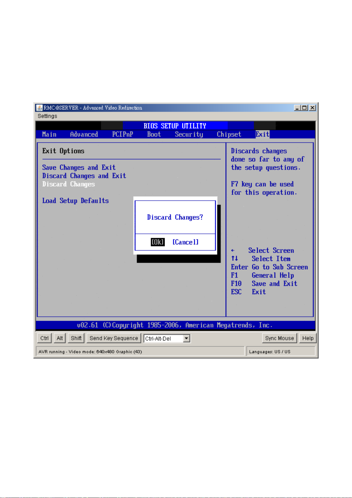
2.9.3 Discard Changes
Select Discard Changes from the Exit menu and press <Enter>.
Discard Changes ?
[Ok] [Cancel]
appears in the window. Select Ok to discard changes.
User’s Manual
AX45Q User’s Manual
81
Page 82

AX45Q
2.9.4 Load Setup Default
Automatically sets all Setup options to a complete set of default settings when you Select
this option. The Optimal settings are designed for maximum system performance, but may
not work best for all computer applications. In particular, do not use the Optimal Setup
options if your computer is experiencing system configuration problems. Select Load Setup
Defaults from the Exit menu and press <Enter>. Select Ok to load optimal defaults.
82 AX45Q User’s Manual
 Loading...