

Page 1
HEARTH PRODUCTS
KITS AND ACCESSORIES
P/N 775258M
Rev. A, 10/2010
INSTALLATION INSTRUCTIONS FOR INSTALLING PILLAR
FACE KITS FOR USE WITH MODELS RAVENNA™,
DESIGNER™ AND RAVELLE™ 30 GAS APPLIANCES
KIT CONTENTS
Please ensure that all these parts are in one of the three boxes. The pillar
face comes packaged in three separate boxes. The following items are
included in each box:
Box 1 - Part # 75093
Cast door with glass installed
Box 2 - Part # 75092
4 ea. Ravelle 30 Mounting Brackets
2 ea. Designer and Ravenna Mounting Brackets
1 ea. Backing Plate With Cast Bottom Attached
8 ea. 5/32” Allen Head Screws
3 ea. Control Knob Extensions
1 ea. Cast Top
1 ea. Left Pillar
1 ea. Right Pillar
Box 3 - Ornate grills (upper and lower grills) - Part # 75091
or
Traditional grills (upper and lower grills) - Part # 75094
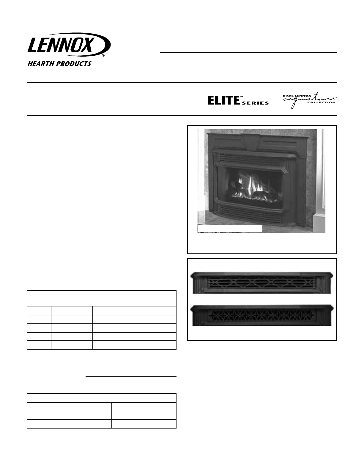
PILLAR FACE KITS
MODELS RAVENNA™, DESIGNER™ AND RAVELLE™ 30
Cast Surround *
Pillared Face
Shown with Traditional Bar Grills
*The cast surround kits are not for use with the Ravelle 30 fireplace.
Figure 1A
Note: The brackets to attach the pillar face assembly to the appliance are
included in the second box. Discard the unused brackets upon completion
of the pillar face assembly.
Pillar Cast Face Kits*
37-5/8" W x 23-3/4" H
Cat. No.
75093 PILCST-GLASS Glass Door (Box 1 of 3)
75092 PILCST-PILRS2 Back, Pillars, Top (Box 2 of 3)
75094 PILCST-GRL-TRD3
75091 PILCST-GRL-FIL3 Ornate Filigree Grills (Box 3 of 3)
Model
Description
Traditional Bar Grills (Box 3 of 3) OR
* Revenna and Designer ONLY - The pillar cast face kits also requires the
use of the surround kits listed below (sold separately - See reference
information on Page 6). The surround kit must be installed prior to
the installation of the pillar cast face kit.
Revenna and Designer Cast Surround Kits (ref. form # 775,292M)
Cat. No. Model Description
75156 RDV-DBV-PCFP3044-TOP, 30 x 44 Top (Box 1 of 2)
75157 RDV-DBV-PCFP3044-SIDES 30 x 44 Sides (Box 2 of 2)
Traditional Bar Grill (75094)
Ornate Filigree Grill (75091)
Figure 1B
TOOLS NEEDED
Phillips Screwdriver
5/32” Allen Wrench or T-Handle Wrench
GENERAL INFORMATION
If you encounter any problems, need clarification of these instructions
or are not qualified to properly install this kit, contact you local distributor or dealer.
Read this instruction sheet in its entirety before beginning the installation.
ALL WARNINGS AND PRECAUTIONS IN THE INSTALLATION AND
OPERATION MANUAL PROVIDED WITH THE APPLIANCE APPLY TO
THESE INSTRUCTIONS.
NOTE: DIAGRAMS AND ILLUSTRATIONS ARE NOT TO SCALE.
1
Page 2
TURN OFF THE FIREPLACE AND ALLOW IT TO COMPLETELY COOL
BEFORE PROCEEDING.
Note: Skip the steps that do not specify your model appliance.
INSTALLATION INSTRUCTIONS
Step 1. Designer™ and Revenna™ inserts - Install the Cast Surround Kit
(sold separately) per the instructions provided in the kit (see Page 1
for ordering information and Page 6 for reference information).
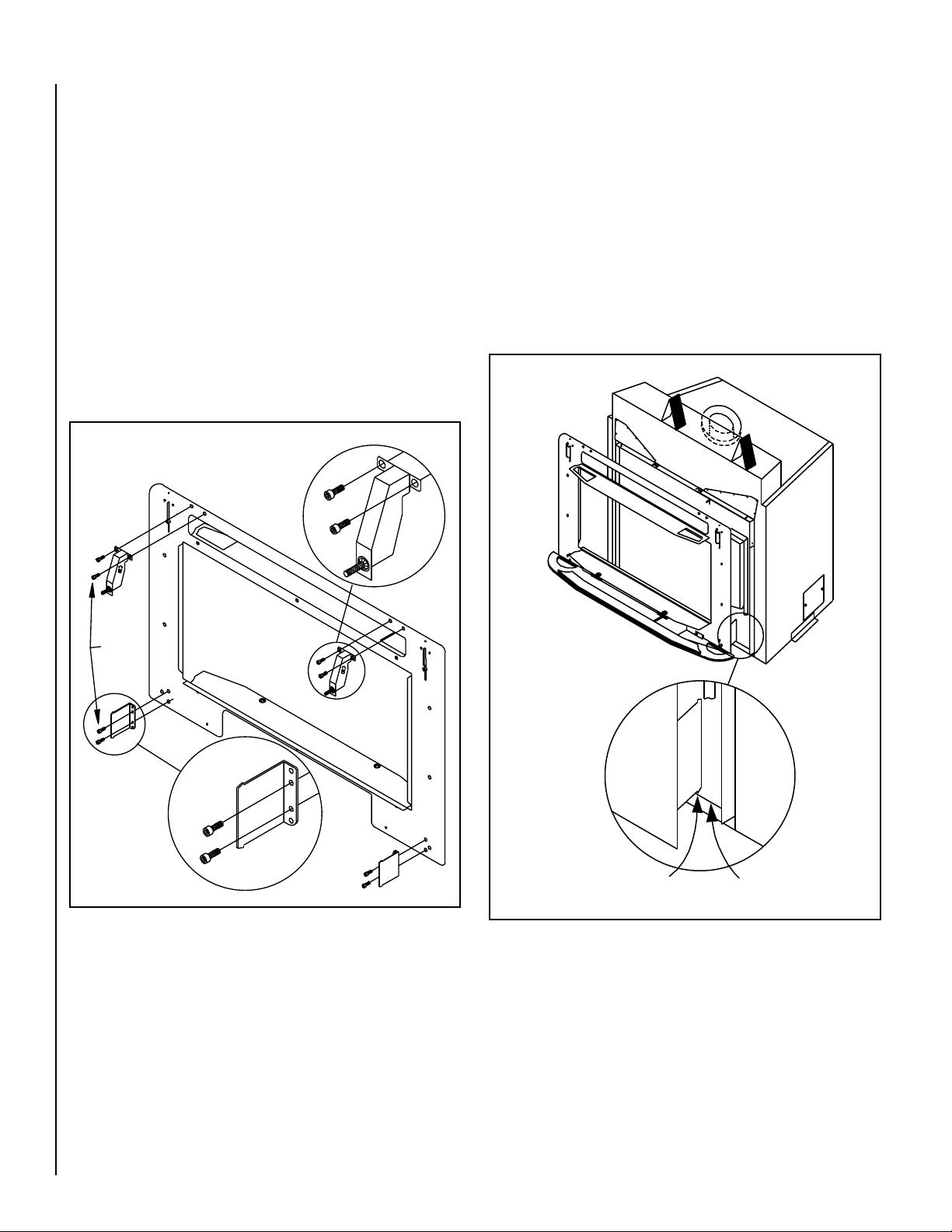
Step 2. Ravelle™ 30 fireplace - Pillar Face Assembly Instructions:
a) Remove the backing plate and the two upper and two lower Ravelle
30 mounting brackets from the box.
b) The two brackets with the captive screws are the upper brackets.
They are interchangeable left to right. Position the upper and lower
brackets as shown below and secure each bracket with two 5/32”
allen head screws (A in Figure 2).
c) See step 3 for instructions on mounting the backing plate to the
Ravelle 30 fireplace.
Expanded View of the Upper
Ravelle 30 Mounting Bracket
R30
Step 3. Ravelle 30 Fireplace - Backing Plate Installation Instructions:
a) There is a 1” lip (see A in Figure 3) at the lower front of the fire-
place. The lower brackets on the backing plate have a hook (see
B in Figure 3) on their bottom edge. The face should be placed so
the hook on the lower bracket catches the 1” lip on the fireplace.
The weight of the backing plate should now be resting on the 1”
lip of the fireplace.
b) The upper brackets (see C in Figure 4), which were installed
on the backing plate following the instructions on the previous
page, contain a captive screw (see D in Figure 4). The captive
screws D on these brackets should be screwed into captive nuts
(see E in Figure 4) on the fireplace. A phillips head screwdriver
inserted through the large hole in the backing plate can be used
to complete this task.
A
Figure 2
Rear View of
Backing Plate
A = 1” Lip
B = Hook on Lower Brackets
Figure 3
AB
2
NOTE: DIAGRAMS AND ILLUSTRATIONS ARE NOT TO SCALE.
Page 3

D
C
E
Turn Deflector so Bent Edge Faces the Front
C = Upper Brackets
D = Captive Screws
E = Captive Nuts
G
Front View of Designer™ and Ravenna Inserts
F = Air Deflector
G = Hex Head Screws
Figure 5
F
H
I
H = Side bracket upper mounting surface
I = Side bracket lower mounting surface
Figure 4
Step 4. Designer™ and Ravenna™ Gas Inserts - Pillar Face Assembly
Instructions:
a) Remove the backing plate and the two mounting brackets from
the box.
b) The brackets should be positioned with the hooks pointing down
and the holes located toward the center of the backing plate (see
Figure 5). Secure each bracket with three 5/32” allen head screws
in the three holes in the backing plate as shown in Figure 6.
Step 5. Designer and Ravenna Gas Inserts - Air Deflector Installation
Instructions:
Packaged with the stove is an air deflector (see F in Figure 5).
Prior to installing the surround panels and pillar face, the air
deflector should be installed by loosening the two 5/32” hex
head screws (see G in Figure 5), positioning the deflector so the
tabs are down and the bent edge is facing the front of the insert,
sliding the tabs on the deflector behind the surround brackets,
and then retightening the screws.
Step 6. Designer and Ravenna Gas Inserts - Backing Plate Installa-
tion Instructions:
The mounting brackets just installed on the backing plate have
two hooks on them. To install the backing plate on the Designer
and Ravenna inserts, lift the backing plate and place the hooks
on the brackets over surfaces H and I (see Figure 5) on the side
surround brackets.
NOTE: DIAGRAMS AND ILLUSTRATIONS ARE NOT TO SCALE.
Rear View of
Backing Plate
Backing Plate for
Designer and Ravenna Inserts
Figure 6
Step 7. All Models - Pillar Installation Instructions:
There is a hole in the top of each pillar (see J in Figure 7). With
the pillar upright (hole J on top) and the vertical fluting to the
outside, place the bottom of the pillar in the semicircular hole in
the cast bottom, while sliding hole H down over hanging bracket
K. Repeat this procedure for the other pillar.
3
Page 4

J
Cast Bottom
Step 9. All Models - Grill Installation Instructions:
Two distinct looks can be obtained by installing either the ornate
grills or the traditional grills on your pillar face (see Figure 1B
on Page 1). The bottom of the grill (see Figure 9) has a return
on it. To install the upper grill (see M in Figure 9), rotate the
K
J = Hole in Top of Pillar
K = Hanging Bracket
grill with the bottom down and place the grill on top of the door.
Push the grill back until it rests against the recess in the pillars.
To install the lower grill (see N in Figure 9), rotate the grill with
the bottom down and place the grill on top of the cast bottom.
Push the grill back until it rests against the two magnets.
M
M = Upper Grill
N = Lower Grill
Figure 7
Step 8. All Models - Door Installation Instructions
Rotate the door so the hooks on the two mounting brackets
attached to the back of the door are pointing down. Each pillar
has two slots (see L in Figure 8). Slide the hooks on the door
brackets into the four slots (L) in the two pillars and push the
door down until the hooks rest in the slots (L).
L = Pillar Mounting Slots
(4 places)
L
N
Bottom of Grill
Figure 9
Figure 8
4
NOTE: DIAGRAMS AND ILLUSTRATIONS ARE NOT TO SCALE.
Page 5

Step 10. All Models - Top Installation Instructions:
The underside of the top has a semicircular recess at both ends.
The pillars have a corresponding semicircular protrusion. Rotate
the top as shown in Figure 10 and position the top so the recess
in each end slides over the protrusions on the pillars (see P in
Figure 10).
P = Protrusions on Pillars
P
Assembled Pillar Face
Figure 10
Step 11. All Models - Face Removal:
To remove the face from the gas appliance, disassemble the
parts in the reverse order of assembly.
Step 12. All Models - Access to the Appliance Controls:
To obtain access to the gas appliance controls, pull the lower
grill forward and set aside. To reinstall, push the grill up against
the magnets for proper alignment.
Figure 11
Step 13. All Models - Extended Knob Installation Instructions:
When installing a cast pillar face on these appliances, use of
these extended knobs are needed for ease of access to the gas
controls.
a) Locate the gas valve controls (see Figure 12).
b) Remove the phillips screw from the pilot/on/off gas control knob
as shown (see Figure 13).
c) Re-install the replacement control knob using the phillips screw
taken out in step b (see Figure 14).
d) Extension knobs can now be pressed on both controls (see Figure
15).
CAUTION: The pillar face is hot while the appliance is
burning. To avoid injury, be sure components are cool
before touching.
NOTE: DIAGRAMS AND ILLUSTRATIONS ARE NOT TO SCALE.
Figure 12
5
Page 6

REFERENCE INFORMATION
Designer™ and Ravenna™ Fireplace Inserts - Figure 16 shows the
dimensions of the cast surround kit. See ordering information on
Page 1.
45-1/2” (1156mm)
7-1/8”
(181mm)
Figure 13
Figure 14
44-1/2” (1130mm)
45-1/2” (1156mm)
Figure 16 - Cast Surround Dimensions
22-7/8”
(581mm)
30”
(762mm)
Figure 15
NOTE: DIAGRAMS AND ILLUSTRATIONS ARE NOT TO SCALE.
Lennox Hearth Products reserves the right to make changes at any time, without notice, in
design, materials, specifications, prices and also to discontinue colors, styles and products.
Consult your local distributor for fireplace code information.
Printed in U.S.A. © 2010 Lennox Hearth Products
P/N 775258M REV. A 10/2010
6
1508 Elm Hill Pike, suite 108 • Nashville, TN 37210
 Loading...