

Lennox HP25, HP25-211, HP25-261, HP25-311, HP25-461-463 Installation Instructions Manual
...
INSTALLATION
PRODUCT LITERATURE
1995 Lennox Industries Inc.
Dallas, Texas
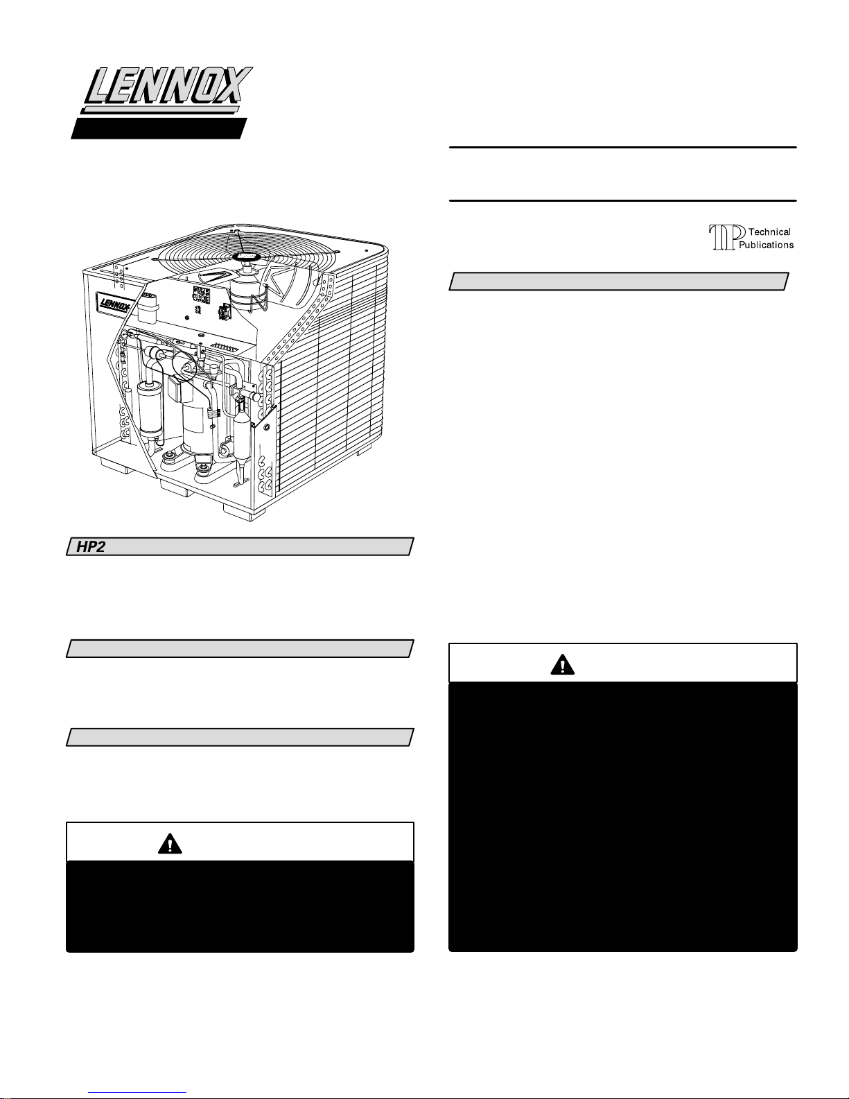
HP25 HEAT PUMP UNIT
HP25 heat pump units are designed for expansion valve
systems only. They are not designed for RFC systems.
Refer to Lennox engineering handbook for expansion
valve kits which must be ordered separately.
INSTRUCTIONS
HP25 SERIES UNITS
HEAT PUMP UNITS
503,302M
6/95
Supersedes 503,247M
TABLE OF CONTENTS
HP25 HEAT PUMP UNIT 1. . . . . . . . . . . . . . . . . . . . . . . . . . . .
SHIPPING AND PACKING LIST 1. . . . . . . . . . . . . . . . . . . . . .
GENERAL INFORMATION 1. . . . . . . . . . . . . . . . . . . . . . . . . .
HP25 UNIT DIMENSIONS 2. . . . . . . . . . . . . . . . . . . . . . . . . .
HP25 PARTS ARRANGEMENT 3. . . . . . . . . . . . . . . . . . . . . .
SETTING THE UNIT 3. . . . . . . . . . . . . . . . . . . . . . . . . . . . . . . .
ELECTRICAL 4. . . . . . . . . . . . . . . . . . . . . . . . . . . . . . . . . . . . . .
PLUMBING 5. . . . . . . . . . . . . . . . . . . . . . . . . . . . . . . . . . . . . . .
REFRIGERATION 5. . . . . . . . . . . . . . . . . . . . . . . . . . . . . . . . . .
LEAK TESTING 6. . . . . . . . . . . . . . . . . . . . . . . . . . . . . . . . . . . .
EVACUATION 6. . . . . . . . . . . . . . . . . . . . . . . . . . . . . . . . . . . . .
START-UP 7. . . . . . . . . . . . . . . . . . . . . . . . . . . . . . . . . . . . . . . .
CHARGING 7. . . . . . . . . . . . . . . . . . . . . . . . . . . . . . . . . . . . . . .
SYSTEM OPERATION 9. . . . . . . . . . . . . . . . . . . . . . . . . . . . . .
DEFROST SYSTEM 9. . . . . . . . . . . . . . . . . . . . . . . . . . . . . . . .
MAINTENANCE 11. . . . . . . . . . . . . . . . . . . . . . . . . . . . . . . . . .
HP25 CHECK POINTS 12. . . . . . . . . . . . . . . . . . . . . . . . . . . . .
RETAIN THESE INSTRUCTIONS
FOR FUTURE REFERENCE
Litho U.S.A.
SHIPPING AND PACKING LIST
1- Assembled HP25 heat pump unit
Check unit for shipping damage. Consult last carrier
immediately if damage is found.
GENERAL INFORMATION
These instructions are intended as a general guide and
do not supersede national or local codes in any way.
Authorities having jurisdiction should be consulted be
fore installation.
IMPORTANT
The Clean Air Act of 1990 bans the intentional
venting of refrigerant (CFC's and HCFC's) as of July
1, 1992. Approved methods of recovery, recycling
or reclaiming must be followed. Fines and/or in
carceration may be levied for non-compliance.
WARNING
Product contains fiberglass wool.
Disturbing the insulation in this product during
installation, maintenance, or repair will expose
you to fiberglass wool. Breathing this may cause
lung cancer. (Fiberglass wool is known to the
State of California to cause cancer.)
Fiberglass wool may also cause respiratory, skin,
and eye irritation.
To reduce exposure to this substance or for further
information, consult material safety data sheets
available from address shown below, or contact
your supervisor.
Lennox Industries Inc.
P.O. Box 799900
Dallas, TX 75379-9900
Page 1
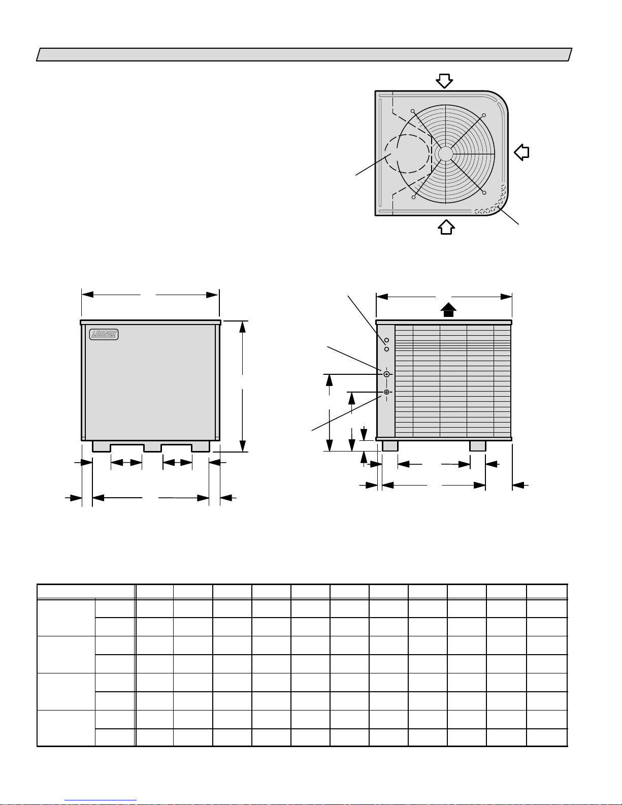
HP25 UNIT DIMENSIONS-INCHES (MM)
HP25211
HP25 311
HP25 511 513
HP25
HEAT PUMP UNIT
B
COMPRESSOR
ELECTRICAL
INLETS
VAPOR
LINE INLET
(HP25211460)
LIQUID
LINE INLET
(HP25510650)
INLET
INLET AIR
AIR
TOP VIEW
C
DISCHARGE AIR
INLET
AIR
COIL DRAIN
OUTLETS
(Around perimeter
of base)
A
LIQUID
LINE INLET
(HP25211460)
VAPOR
LINE INLET
(HP25510650)
KK
LL
47/8 (22)
GHH
FRONT VIEW
Model No. A B C D E F G H J K L
HP25211
HP25261
HP25311
HP25411413
in. 277/8 257/8 297/8 121/4 227/16 147/16 221/8 17/8 163/4 51/2 27/8
mm 708 657 759 311 570 367 562 48 425 140 73
in. 307/8 321/8 341/16 123/4 265/8 185/8 281/8 2 171/4 71/2 37/8
mm 784 816 865 324 676 473 714 51 438 191 98
J
23/4
(70)
D
13/8
(35)
4
(102)
F
E
SIDE VIEW
4
(102)
61/16
(154)
HP25461463
HP25511513
HP25651653
in. 347/8 321/8 341/16 133/4 265/8 185/8 281/8 2 181/4 71/2 37/8
mm 886 816 865 349 676 473 714 51 464 191 98
in. 447/8 321/8 341/16 291/4 265/8 185/8 281/8 2 203/4 71/2 37/8
mm 1140 816 865 743 676 473 714 51 527 191 98
Page 2
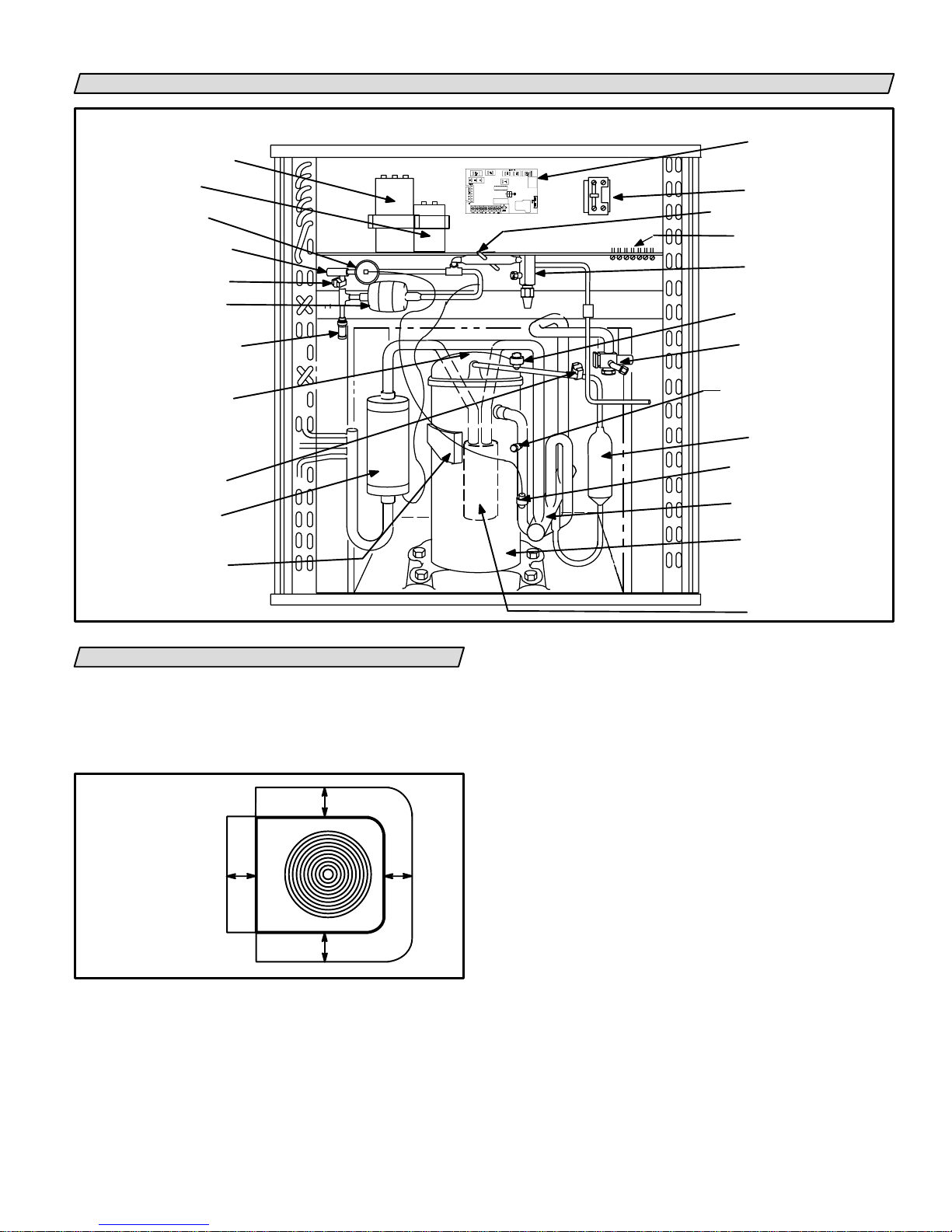
HP25 PARTS ARRANGEMENT
HP25 UNIT COMPONENTS
DUAL CAPACITOR
(Single-Phase Units)
FAN CAPACITOR
(Three-Phase Units)
EXPANSION
VAL VE
DISTRIBUTOR
DEFROST
THERMOSTAT
FILTER/DRIER
WITH
INTERNAL CHECK VALVE
FACTORY
CHARGE
PROCESS PORT
COMPRESSOR
TEMPERATURE
SENSOR
HP25211 THRU 460 ONLY
SERVICE LIGHT
THERMOSTAT
CHARGE
COMPENSATOR
COMPRESSOR
TERMINAL BOX
FIGURE 1
SETTING THE UNIT
HP25 heat pump units are approved and warranted
only for installation with specially matched indoor
coils, L10 or L15 line sets, and refrigerant control de
vices as designated by Lennox. Refer to the Lennox En
gineering Handbook for approved systems.
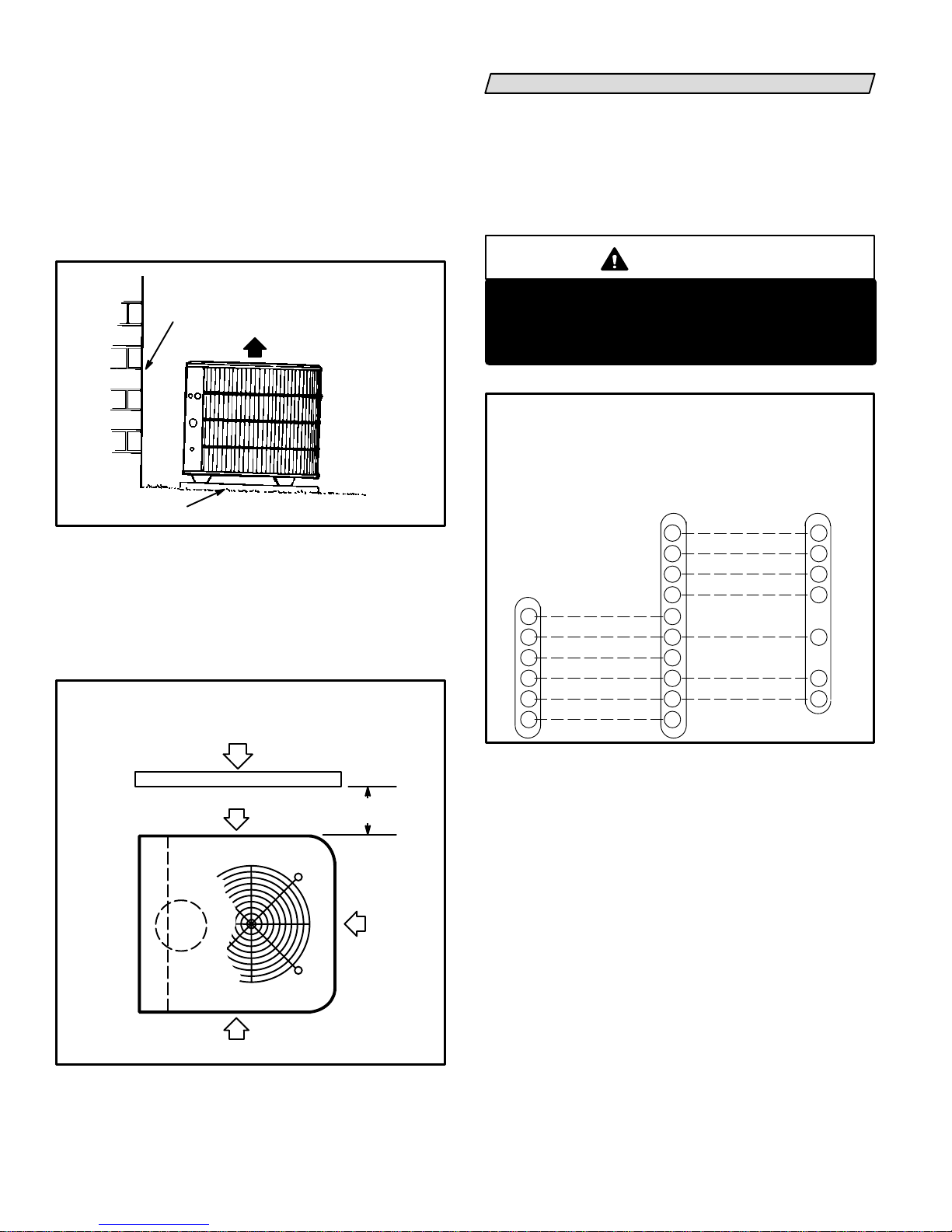
INSTALLATION
CLEARANCES
NOTE-48"
(1219mm)
clearance required
on top of unit.
*One side dimension
may be 12" (305mm).
36"
(914mm)
*36"
(914mm)
FIGURE 2
Heat pump units operate under a wide range of weath
er conditions; therefore, several factors must be con
sidered when positioning the outdoor unit.
*36"
(914mm)
*36"
(914mm)
DEFROST CONTROL
CONTACTOR
THERMOMETER WELL
TERMINAL STRIP
LIQUID LINE
SERVICE VALVE
AND GAUGE PORT
HIGH PRESSURE SWITCH
VAPOR LINE
SERVICE VALVE
AND GAUGE PORT
SUCTION GAUGE PORT
MUFFLER
EXPANSION VALVE
SENSING BULB
REVERSING VALVE
AND SOLENOID
COMPRESSOR
ACCUMULATOR
HP25510 AND
-650 ONLY
1- Place a sound-absorbing material, such as Iso
mode, under the unit if it will be installed in a loca
tion or position that will transmit sound or vibra
tion to the living area or adjacent buildings.
2- Mount unit high enough above ground or roof to al
low adequate drainage of defrost water and prevent
ice build-up.
3- In heavy snow areas, do not locate unit where drift
ing will occur. The unit base should be elevated
above the depth of average snows.
NOTE-Elevation of the unit may be accomplished
by constructing a frame using suitable materials. If
a support frame is constructed, it must not block
drain holes in unit base.
4- When installed in areas where low ambient tem
peratures exist, locate unit so winter prevailing
winds do not blow directly into outdoor coil.
5- Locate unit away from overhanging roof lines
which would allow water or ice to drop on, or in
front of, coil or into unit.
Page 3
Slab Mounting (See figure 3)
When installing unit at grade level, top of slab should
be high enough above the grade so that water from
higher ground will not collect around unit. Slab should
have a slope tolerance away from the building of 2 de
grees or 2 inches per 5 feet (51mm per 1.5m). This will
prevent ice build-up under unit during a defrost cycle.
Refer to roof mounting section for barrier construction
if unit must face prevailing winter winds.
SLAB MOUNTING
BUILDING
STRUCTURE
MOUNTING SLAB
DISCHARGE
AIR
2 DEGREES or 2 IN. PER 5 FT.
(51mm per 1.5m)
TOLERANCE AWAY FROM
BUILDING STRUCTURE
SLOPE
GROUND LEVEL
FIGURE 3
Roof Mounting (See figure 4)
If unit coil cannot be mounted away from prevailing
winter winds, a wind barrier should be constructed.
Size barrier at least the same height and width as out
door unit. Mount barrier 24 inches (610mm) from the
sides of the unit in the direction of prevailing winds.
ROOFTOP APPLICATION
WIND BARRIER CONSTRUCTION
PREVAILING WINTER WINDS
WIND BARRIER
INLET AIR
24"
(610mm)
ELECTRICAL
Wiring must conform to the National Electric Code
(NEC) and local codes. Application diagram is included
in this instruction (see figure 6) and in indoor unit
instructions. Refer to figure 5 for thermostat designa
tions. Refer to unit rating plate for minimum circuit am
pacity and maximum fuse size.
WARNING
Unit must be grounded in accordance with
national and local codes.
Electric Shock Hazard.
Can cause injury or death.
HP25 and BLOWER UNIT
THERMOSTAT DESIGNATIONS
(WITH OR WITHOUT AUXILIARY HEAT)
(Some connections may not apply.
Refer to specific thermostat and indoor unit.)
HP25ThermostatIndoor
Blower
Unit
EMERGENCY HEAT
E
C
W2
R
W1
G
COMMON
2ND STAGE AUX. HEAT
POWER
1ST STAGE AUX. HEAT
INDOOR BLOWER
FIGURE 5
1- Provide line voltage power supply to unit from a
properly sized disconnect switch. See figure 6.
AMBIENT SENSOR
T
SERVICE LIGHT
L
REVERSING VALVE
O
COMPRESSOR
Y1
E
C
W2
R
W1
G
COMMON
POWER
DEFROST SENSING/
1ST STAGE AUX. HEAT
T
L
O
Y1
C
R
W1
INLET AIR
FIGURE 4
INLET
AIR
2- Install room thermostat (ordered separately) in
the conditioned area. Locate where it will not be
affected by sunlight, drafts or vibration. Do not
install on an outside wall. A position approxi
mately 5 feet (1.5m) from the floor and near the
center of the conditioned area is most desirable.
3- Provide low voltage wiring from outdoor to indoor
unit and from thermostat to indoor unit as indi
cated on the field wiring diagram in this instruc
tion. See figure 6.
4- Ground unit either through supply wiring or with
an earth ground.
Page 4

FIELD WIRING DIAGRAM HP25 WITH CB19
DEFROST CONTROL
K1
C12
TLCRW1Y1O
DENOTES OPTIONAL COMPONENT
1
THERMOSTAT HEAT ANTICIPATION SET
TING .4 AMP ELECTRIC HEAT.
2
WHEN TWO-STAGE THERMOSTAT IS USED,
CONNECT SECOND-STAGE HEAT BULB TO TER
MINAL W2" AND REMOVE JUMPER BETWEEN
TERMINALS R" AND W2."
WHEN OUTDOOR THERMOSTAT IS USED,
3
CONNECT LEADS TO TERMINALS R"
AND W2'' AND REMOVE JUMPER BE
TWEEN TERMINALS R" AND W2."
FIGURE 6
PLUMBING
Field refrigerant piping consists of liquid and vapor
lines from the outdoor unit (sweat connections). Use
Lennox L10 (flare) or L15 (sweat) series line sets as
shown in table 1 or field-fabricated refrigerant lines.
Refer to the piping section of the Lennox Unit Informa
tion Service Manual for proper size, type and applica
tion of field-fabricated lines.
If refrigerant tubes are routed through a wall, seal and
isolate the opening so vibration is not transmitted to
the building.
NOTELine length should be no greater than 50 feet
(15.2 m). Select line set diameters from table 1 to en
sure oil return to compressor.
TABLE 1
REFRIGERANT LINE SET KITS
HP25
UNIT
-211
-261
-311
-410
-460
-510
-650
LIQUID VAPOR
LINE LINE
3/8 in.
(9.5 mm)
3/8 in. 3/4 in.
(9.5 mm) (19.1 mm)
3/8 in.
(9.5 mm)
3/8 in.
(9.5 mm)
5/8 in.
(15.9 mm)
7/8 in.
(22.2 mm)
1-1/8 in.
(28.6 mm)
L10
LINE SETS
L10-26
20 ft. - 50 ft.
(6.1 m-15.2 m)
L10-41
20 ft. - 50 ft.
(6.1 m-15.2 m)
L10-65
30 ft. - 50 ft.
(9.1 m - 15.2 m)
FIELD
FABRICATED
NOTE-To obtain maximum efficiency, remove the 3/4"
(19.1mm) reduction from the L10-65 series line sets
and the flare fitting from the indoor coil. Then, make a
sweat connection using a 7/8" X 1-1/8"(22.2mm x
28.6mm) reducer bushing.
L15
LINE SETS
L15-26
20 ft. - 50 ft.
(6.1 m-15.2 m)
L15-41
20 ft. - 50 ft.
(6.1 m-15.2 m)
L15-65
30 ft. - 50 ft.
(9 .1 m-15.2 m)
FIELD
FABRICATED
L O Y1 E C V/R R W1 G
T
4
3
S23
EMERGENCY HEAT RELAY (USED ONLY
4
IF OUTDOOR THERMOSTAT IS USED)
FIELD PROVIDED AND INSTALLED NEAR
INDOOR UNIT. 24 VAC, 5VA MAX. NEC
CLASS 2.
K22
CLASS II 24V FIELD INSTALLED
LINE VOLTAGE FIELD INSTALLED
REFRIGERATION
Processing Procedure
The unit is factory-charged with the amount of R-22
(HCFC-22) refrigerant indicated on the unit rating
plate. This charge is based on a matching indoor coil
and outdoor coil with a 20 foot (6.1m) line set. For vary
ing lengths of line set, refer to table 2 for refrigerant
charge adjustment. A blank space is provided on the
unit rating plate to list actual field charge.
TABLE 2
LINE SET DIAMETER
Vapor Liquid
5/8 in. 3/8 in. 3 ounce
(15.9mm) (9.5 mm) (88.05 g)
3/4 in.
(19.1mm)
7/8 in.
(22.2mm)
1-1/8 in.
(28.6mm)
*If line set length is greater than 20 ft. (6.1m), add this amount. If line
set length is less than 20 ft. (6.1m), subtract this amount.
3/8 in.
(9.5 mm)
3/8 in.
(9.5 mm)
3/8 in.
(9.5 mm)
Service Valves and Gauge Manifold Attachment
The liquid line and vapor line service valves and
gauge ports are accessible on the inside of the unit.
These gauge ports are used for leak testing, evacuat
ing, charging and checking charge. A separate gauge
port is provided for checking the suction pressure
when the unit is in the heating cycle.
IMPORTANT-Service valves are closed to the heat
pump unit and open to line set connections. Do not
open until refrigerant lines have been leak tested and
evacuated. All precautions should be exercised in
keeping the system free from dirt, moisture and air.
Ozs. per 5 ft. (g per 1.5m)
adjust from 20 ft.
(6.1m) line set*
3 ounce
(88.05 g)
3 ounce
88.05 g)
3 ounce
(88.05 g)
Page 5

LEAK TESTING
After the line set has been connected to the indoor and
outdoor units, the line set connections and indoor unit
must be checked for leaks.
WARNING
Never use oxygen to pressurize refrigeration or air
conditioning system. Oxygen will explode on con
tact with oil and could cause personal injury. When
using high pressure gas such as nitrogen or CO2 for
this purpose, be sure to use a regulator that can
control the pressure down to 1 or 2 psig (6.9 to 13.8
kPa).
Using an Electronic Leak Detector or Halide
1- Connect a cylinder of nitrogen with a pressure reg
ulating valve to the center port of the manifold
gauge set.
2- Connect the high pressure hose of the manifold
gauge set to the service port of the vapor valve.
(Normally, the high pressure hose is connected to
the liquid line port, however, connecting it to the
vapor port better protects the manifold gauge set
from high pressure damage.)
3- With both manifold valves closed, open the valve
on the R22 bottle (vapor only).
4- Open the high pressure side of the manifold to al
low R22 into the line set and indoor unit. Weigh in a
trace amount of R22. [A trace amount is a maxi
mum of 2 ounces (57g) refrigerant or 3 pounds (31
kPa) pressure]. Close the valve on the R22 bottle
and the valve on the high pressure side of the man
ifold gauge set. Disconnect R22 bottle.
5- Adjust nitrogen pressure to 150 psig (1034 kPa). Open
the valve on the high side of the manifold gauge set
which will pressurize line set and indoor unit.
6- After a short period of time, open a refrigerant port
to make sure the refrigerant added is adequate to
be detected. (Amounts of refrigerant will vary with
line lengths.) Check all joints for leaks. Purge nitro
gen and R22 mixture. Correct any leaks and re
check.
EVACUATING
Evacuating the system of non-condensables is critical
for proper operation of the unit. Non-condensables are
defined as any gas that will not condense under temper
atures and pressures present during operation of an air
conditioning system. Non-condensables and water va
por combine with refrigerant to produce substances
that corrode copper piping and compressor parts.
1- Connect manifold gauge set to the service valve ports
as follows: low pressure gauge to vapor line service
valve; high pressure gauge to liquid line service valve.
2- Connect the vacuum pump (with vacuum gauge)
to the center port of the manifold gauge set.
3- Open both manifold valves and start vacuum
pump.
4- Evacuate the line set and indoor unit to an absolute
pressure of 23mm of mercury or approximately 1
inch of mercury. During the early stages of evacua
tion, it is desirable to close the manifold gauge
valve at least once to determine if there is a rapid
rise in absolute pressure. A rapid rise in pressure
indicates a relatively large leak. If this occurs, the
leak testing procedure must be repeated.
NOTE - The term absolute pressure means the to
tal actual pressure within a given volume or sys
tem, above the absolute zero of pressure. Absolute
pressure in a vacuum is equal to atmospheric pres
sure minus vacuum pressure.
5- When the absolute pressure reaches 23mm of mer
cury, close the manifold gauge valves, turn off the
vacuum pump and disconnect the manifold gauge
center port hose from vacuum pump. Attach the
manifold center port hose to a nitrogen cylinder
with pressure regulator set to 150 psig (1034 kPa)
and purge the hose. Open the manifold gauge
valves to break the vacuum in the line set and in
door unit. Close the manifold gauge valves.
CAUTION
Danger of Equipment Damage.
Avoid deep vacuum operation. Do not use com
pressors to evacuate a system.
Extremely low vacuums can cause internal arcing
and compressor failure.
Damage caused by deep vacuum operation will
void warranty.
6- Shut off the nitrogen cylinder and remove the man
ifold gauge hose from the cylinder. Open the man
ifold gauge valves to release the nitrogen from the
line set and indoor unit.
7- Reconnect the manifold gauge to the vacuum
pump, turn the pump on and continue to evacuate
the line set and indoor unit until the absolute pres
sure does not rise above .5mm of mercury within a
20 minute period after shutting off the vacuum
pump and closing the manifold gauge valves.
8- Depending on the equipment used to determine
the vacuum level, absolute pressure of .5mm of
mercury is equal to 500 microns.
Page 6

3.57kg) 9- When the absolute pressure require
ment above has been met, disconnect the manifold
hose from the vacuum pump and connect it to an
upright bottle of R22 refrigerant. Open the manifold
gauge valves to break the vacuum in the line set and
indoor unit. Close manifold gauge valves and shut
off R22 bottle and remove manifold gauge set.
START-UP
IMPORTANT
1- Disconnect power to the unit.
2- Reverse any two field power leads to the unit.
3- Reapply power to the unit.
Discharge and suction pressures should operate at
their normal start-up ranges.
NOTE-Compressor noise level will be significantly
higher when phasing is incorrect and the unit will not
provide cooling when compressor is operating back
wards. Continued backward operation will cause the
compressor to cycle on internal protector.
HP25-413/463-1Y three-phase units only-Crank
case heater must be energized 24 hours before at
tempting to start compressor. Compressor dam
age may occur from slugging. To prevent com
pressor operation, set thermostat demand so
there is no demand. Apply power to unit.
Cooling Start-up
1- Rotate fan to check for frozen bearings or binding.
2- Inspect all factory and field-installed wiring for
loose connections.
3- Open liquid line and vapor line service valves to re
lease refrigerant charge (contained in heat pump
unit) into the system.
4- Replace stem caps and secure finger tight plus an
additional 1/6th turn.
5- Check voltage supply at the disconnect switch.
The voltage must be within the range listed on the
unit nameplate. If not, do not start the equipment
until the power company has been consulted and
the voltage condition corrected.
6- Set the thermostat for a cooling demand, turn on
power to the indoor blower coil and close heat
pump unit disconnect switch to start the unit.
7- Recheck unit voltage with unit running. Power
must be within range shown on unit nameplate.
Check amperage draw of unit. Refer to unit name
plate for correct running amps.
Three-Phase Compressor Rotation
Three-phase scroll compressors must be phased se
quentially to ensure correct compressor rotation and
operation. At compressor start-up, a rise in discharge
and drop in suction pressures indicate proper com
pressor phasing and operation. If discharge and suc
tions pressures do not perform normally, follow the
steps below to correctly phase in the unit.
CHARGING
It is desirable to charge the system in the cooling cycle
if weather conditions permit. However, if the unit must
be charged in the heating season, one of the following
procedures must be followed to ensure proper system
charge.
If the system is completely void of refrigerant, the rec
ommended and most accurate method of charging is
to weigh the refrigerant into the unit according to the
total amount shown on the unit nameplate and in table
3. Refer to the Lennox Unit Information Service manual
for proper procedure.
TABLE 3
Model Refrigerant Charge R-22
HP25-211
HP25-261 8 lbs. 14 oz. (4.03 kg)
HP25-311
HP25-410
HP25-460
HP25-510 18 lbs. 8 oz. (8.39 kg)
HP25-650
If weighing facilities are not available or if unit is just
low on charge, use the following procedure:
1- Connect gauge manifold as shown in figure 7.
Connect an upright R-22 (HCFC-22) drum to center
port of gauge manifold.
2- Record outdoor ambient temperature.
3- Set room thermostat to 74F (23C) in Emergen
cy Heat" or Heat" position and allow unit to run
until heating demand is satisfied. This will create
the necessary load for proper charging of system
in cooling cycle. Change thermostat setting to
68F (20C) in Cool" position. Allow unit to run
until system pressures stabilize.
4- Check to make sure that thermometer well is filled
with mineral oil before checking liquid line tem
perature.
7 lbs. 10 oz. (3.46 kg)
10 lbs. 4 oz. (4.65 kg)
11 lbs.4 oz. (5.10 kg)
12 lbs. 8 oz. (5.67 kg)
23 lbs. 14 oz. (10.83 kg)
Page 7

HP25 COOLING CYCLE
(Showing Gauge Manifold Connections)
EXPANSION
VALVE
CHARGE COMPENSATOR
REVERSING
VALVE
SUCTION
HIGH
PRESSURE
FILTER DRIER
WITH INTERNAL
CHECK VALVE
LIQUID
LINE
VALVE
THERMOMETER
WELL
NOTE-Use gauge ports on vapor line valve and liquid valve for evacuating refrigerant lines
and indoor coil. Use suction gauge port to measure suction pressure during charging.
STRAINER
DISCHARGE
MUFFLER
COMPRESSOR
FIGURE 7
5- If outdoor temperature is 60F (15C) or above,
place thermometer in well and read liquid line
temperature. Difference between ambient and liq
uid line temperatures should match values given
in table 4. Refrigerant must be added to lower ap
proach temperature. Remove refrigerant from sys
tem to increase approach temperature.
Approach Method-Expansion Valve Systems
TABLE 4
Model
HP25-211
HP25-261 8 (4)
HP25-311
HP25-410
HP25-460
HP25-510
HP25-650
Liquid Temp. Minus
Ambient Temp. F (C)
8 (4)
8 (4)
9 (5)
9 (5)
5 (3)
5 (3)
7- Read liquid line temperature. Read liquid line pres
6- If ambient temperature is less than 60F (15C), air
flow might need to be restricted to achieve pressur
es in the 200-250 psig (1379-1724 kPa) range (See
figure 8). These higher pressures are necessary for
checking charge. Block equal sections of air intake
panels, moving obstructions sideways as shown
until liquid pressure is in the 200-250 psig
(1379-1724 kPa) range.
VAPOR LINE
VALVE
INDOOR
UNIT
CHECK
VALVE
EXPANSION
VALVE
BLOCKING OUTDOOR COIL
OUTDOOR COIL SHOULD BE BLOCKED
ONE SIDE AT A TIME WITH CARDBOARD
OR PLASTIC SHEET UNTIL PROPER TEST
ING PRESSURES ARE REACHED.
CARDBOARD OR PLASTIC SHEET
FIGURE 8
sure from gauge and convert to condensing tem
perature using standard R-22 temperature/pres
sure conversion chart. The difference between the
liquid line temperature and the conversion temper
ature is the subcooling temperature (subcooling =
conversion temperature minus liquid tempera
ture). Subcooling should approximate values given
in table 5. Add refrigerant to increase subcooling
and remove refrigerant to reduce subcooling.
TABLE 5
Subcooling Method-Expansion Valve Systems
Model Subcooling F (C)
HP25-211 8 + 2 (4 + 1)
HP25-261/311/410
HP25-460
HP25-510
HP25-650
3 +
8 +
10 +
12 +
2 (2 + 1)
2 (4 + 1)
2 (6 + 1)
2 (7 + 1)
Page 8

Compressor Oil Charge
Table 6 gives compressor oil charge for HP25 units. Re
fer to Lennox Cooling Service Handbook for correct pro
cedure for checking and adding compressor oil.
TABLE 6
COMPRESSOR OIL CHARGE
UNIT MODEL NO.
HP25-211
HP25-261 & -311 28 oz.* (0.83 L)
HP25-410
HP25-460 38 oz.* (1.12 L)
HP25-510 52 oz.* (1.54 L)
HP25-650 54 oz.* (1.60 L)
*Shipped with conventional white oil (Sontex 200LT). 3GS oil may be
used if additional oil is required.
COMPRESSOR OIL CHARGE
ounces (liters)
24 oz.* (0.71 L)
34 oz.* (1.01 L)
SYSTEM OPERATION
Discharge Thermostat
The scroll compressor is equipped with a discharge
thermostat which prevents the occurrence of danger
ously high discharge temperatures. This thermostat
cuts in at 130F (54C) and cuts out at 280F (138C) .
CAUTION
Danger of Equipment Damage.
Do not bypass the discharge thermostat.
Filter Drier
The drier is equipped with an internal check valve for
correct refrigerant flow (Refer to figure 7). If replace
ment is necessary, order another of like design and ca
pacity. A liquid line strainer gives additional compressor
protection.
Thermostat Operation
Some heat pump thermostats incorporate isolating
contacts and an emergency heat function (which in
cludes an amber indicating light). The thermostat is
not included with the unit and must be purchased
separately.
Emergency Heat (Amber Light)
An emergency heat function is designed into some ther
mostats. This feature is applicable only to those systems
with auxiliary electric heat staged by outdoor thermo
stats. When the thermostat is placed in the emergency
heat position, the outdoor unit control circuit is isolated
from power and field-provided relays by-pass the out
door thermostats. An amber indicating light simulta
neously comes on to remind the homeowner that the
unit is operating in the emergency heat mode.
Emergency heat is usually used during a heat pump
shutdown.
Compressor Timed-Off Control
This unit is equipped with a time delay which protects
the compressor by preventing short-cycling.
High Pressure Switch
The HP25 is equipped with an auto-reset high pressure
switch (single-pole, single-throw) which is located on
the liquid line. The switch shuts off the compressor
when discharge pressure rises above the factory set
ting. The switch is normally closed and is permanently
adjusted to trip (open) at 410 +
10 psig (2827 + 69 kPa).
The switch resets (closes) when the pressure drops be
low 210 +
20 psig ( 1448+138 kPa).
Crankcase Heater
HP25-413 & -463-1Y three-phase units only are
equipped with a crankcase heater which must be ener
gized for 24 hours before attempting to start compres
sor. To prevent compressor operation, set thermostat
so there is no demand. Apply power to unit.
DEFROST SYSTEM
The defrost system includes two components: a de
frost thermostat, and a defrost control.
Defrost Thermostat
The defrost thermostat is mounted on the liquid line be
tween the check/expansion valve and the distributor.
When defrost thermostat senses 35F (2C) or cooler, its
contacts close and send a signal to the defrost control
board to start the defrost timing. It also terminates de
frost when the liquid line warms up to 70F (21C).
Defrost Control
The defrost control board has the combined func
tions of a time/temperature defrost control, defrost
relay, time delay, diagnostic LEDs and field connec
tion terminal strip.
The control provides automatic switching from normal
heating operation to defrost mode and back. During
compressor cycle (call for defrost), the control accumu
lates compressor run times at 30, 60 or 90 minute field
adjustable intervals. If the defrost thermostat remains
closed when the accumulated compressor run time
ends, the defrost relay is energized and defrost begins.
Defrost Control Timing Pins
Each timing pin selection provides a different accu
mulated compressor run period during one thermo
stat run cycle. This time period must occur before a
defrost cycle is initiated. The defrost interval can be
adjusted to 30, 60 or 90 minutes. See figure 9. The de
frost period is a maximum of 14 minutes and cannot
be adjusted. If no timing is selected, the control de
faults to 90 minutes.
A TEST option is provided for troubleshooting. When
the jumper is placed across the TEST pins, the timing of
all functions is reduced by a factor of 128. For example,
a 90 minute interval during TEST is 42 seconds and the
14 minute defrost is reduced to 6.5 seconds.
Page 9

The TEST mode may be started at anytime. If the jumper
is in the TEST position at power-up or for longer than
five minutes, the control will ignore the TEST selection
and will default to a 90 minute interval.
Time-Delay
The timed-off delay is five minutes long. The delay fea
ture is provided to help protect the compressor in
cased of an interruption in power to the unit or when a
pressure switch resets.
Pressure Switch Safety Circuits
The defrost control incorporates a pressure switch safe
ty circuit that allows the application of an additional
pressure switch; high pressure switch (S4) is factorywired to this circuit. See figure 9. PS1 and PS2 terminals
are wired in series with a jumper internal to the control
board. This feature is available on all units.
During one demand cycle, the defrost control will lock
out the unit on the third instance that the unit goes off
on any auto-reset pressure switch wired to this circuit.
The diagnostic LEDs will display a pattern for a locked
out pressure switch on the third open pressure switch
occurrence. See table 7. The unit will remain locked out
until power is broken then remade to the control.
For HP25-211/461 units, the PS2 safety circuit termi
nals are connected to the compressor thermostat. An
optional loss of charge switch may be field-installed by
connecting it in series with the other switches. See unit
wiring diagram.
HP25-511/651 units are equipped with a factoryinstalled jumper over the two safety circuit PS2 termi
nals on the defrost board. If using an additional pres
sure switch, remove jumper before connecting
additional switch to control board. If no additional
switch is needed, DO NOT REMOVE JUMPER. Unit will
not operate without jumper in place in this case.
For three-phase units, the factory-installed high pres
sure switch is connected to the two outside terminals
of the pressure switch connections. If adding another
pressure switch, remove lead from outer PS2 terminal
and connect it to inside terminal of PS1. Connect addi
tional pressure switch leads to PS2 set of safety circuit
terminals. See figure 9.
FACTORY CONNECTIONS FOR
HP25-511/651 UNITS ONLY
S4
High Pressure
To add additional pressure switch, remove jumper and
connect optional switch leads to PS2 terminals. If no
other pressure switch is added, jumper must stay in
To add additional pressure switch, remove lead from
outer PS2 terminal and connect to inside PS1 terminal.
To add additional pressure switch, such as loss of
charge switch, wire it in series with the two factory-
installed switches. See unit wiring diagram for details.
place for proper unit operation.
FACTORY CONNECTION FOR
THREE-PHASE UNITS ONLY
S4
High Pressure
Connect optional switch leads to PS2 terminals.
FACTORY CONNECTIONS FOR
HP25-211/461 UNITS ONLY
S5
Compressor
Thermostat
S4
High Pressure
DEFROST CONTROL BOARD
PRESSURE
SWITCH
SAFETY CIRCUIT
CONNECTIONS
NOTE- There is an internal jumper between inside PS1 and PS2 terminals.
FACTORY-INSTALLED
JUMPER
HP25-511/651 ONLY.
(Remove to add
pressure switch)
AMBIENT
THERMISTOR
CONNECTION
SERVICE LIGHT
CONNECTION
DIAGNOSTIC
LEDs
DEFROST
INTERVAL
TIMING PINS
24V TERMINAL
STRIP
CONNECTIONS
FIGURE 9
Page 10

Diagnostic LEDs
The defrost board uses two LEDs for diagnostics. The
LEDs flash a specific sequence according to the
condition.
TABLE 7
DEFROST CONTROL BOARD DIAGNOSTIC LED
MODE LED 1 LED 2
Normal Operation/
Power to board
Time Delay
To Protect Compressor
Pressure Switch Open Off On
Pressure Switch Lockout On Off
Board Malfunction On On
Flash together
with LED 2
Alternating Flashes
with LED 2
Flash together with
LED 1
Alternating Flashes
with LED 1
Ambient Thermistor & Service Light Connection
The defrost control board provides terminal connec
tions for the ambient thermistor and service light.
These features provide a service light thermostat
which activates the room thermostat service light dur
ing periods of inefficient operation. The thermistor
compensates for changes in ambient temperature
which might cause thermostat droop.
MAINTENANCE
WARNING
Electric shock hazard. Can cause injury
or death. Before attempting to per
form any service or maintenance, turn
the electrical power to unit OFF at dis
connect switch(es). Unit may have
multiple power supplies.
At the beginning of each heating or cooling season, the
system should be cleaned as follows:
Heat Pump Unit
1- Clean and inspect outdoor coil. (Coil may be
flushed with a water hose.)
2- Outdoor coil fan motor is prelubricated and
sealed. No further lubrication is needed.
3- Visually inspect all connecting lines, joints and
coils for evidence of oil leaks.
4- Check all wiring for loose connections.
5- Check for correct voltage at unit (unit operating).
6- Check amp-draw on heat pump fan motor.
Unit nameplate_______Actual_______.
7- Inspect drain holes in coil compartment base and
clean if necessary.
NOTE-If insufficient heating or cooling occurs, the unit
should be gauged and refrigerant charge checked.
Indoor Coil
1- Clean coil if necessary.
2- Check connecting lines, joints and coil for evi
dence of oil leaks.
3- Check condensate line and clean if necessary.
Indoor Unit
1- Clean or change filters.
2- Adjust blower speed for cooling. The pressure drop
over the coil should be checked to determine the cor
rect blower air volume. Refer to the Lennox Engi
neering Handbook for indoor unit blower perfor
mance tables.
3- Check all wiring for loose connections.
4- Check for correct voltage at unit.
5- Check amp-draw on blower motor.
Motor nameplate_______Actual_______.
Page 11

HP25 CHECK POINTS
START-UP AND PERFORMANCE CHECK LIST
Job Name
Job Location
Installer
Unit Model No.
Nameplate Voltage
Minimum Circuit Ampacity
Maximum Overcurrent Protection Size
Electrical Connections Tight?
Supply Voltage (Unit Off)
COOLING SECTION
Refrigerant Lines:
Job No.
City
City
Serial No.
Amps:
Supply Outdoor Fan
Compressor
Indoor Filter Clean?
Indoor Blower RPM
S.P. Drop Over Evaporator (Dry)
Outdoor Entering Air Temperature
Service Technician
Date
State
State
Leak Checked?
Service Valves Backseated?
Properly Insulated?
Outdoor Fan Checked?
Service Valve Caps Tight?
Voltage With Compressor Operating
Discharge Pressure Suction Pressure
Refrigerant Charge Checked?
THERMOSTAT
Calibrated? Properly Set?
Level?
Page 12
 Loading...