

Lennox HP13 Series Installation Instructions Manual
INSTALLATION
';_)2007 Lennox industries Jnc,
0( us
RETAIN THESE INSTRUCTIONS
FOR FUTURE REFERENCE
A CAUTION
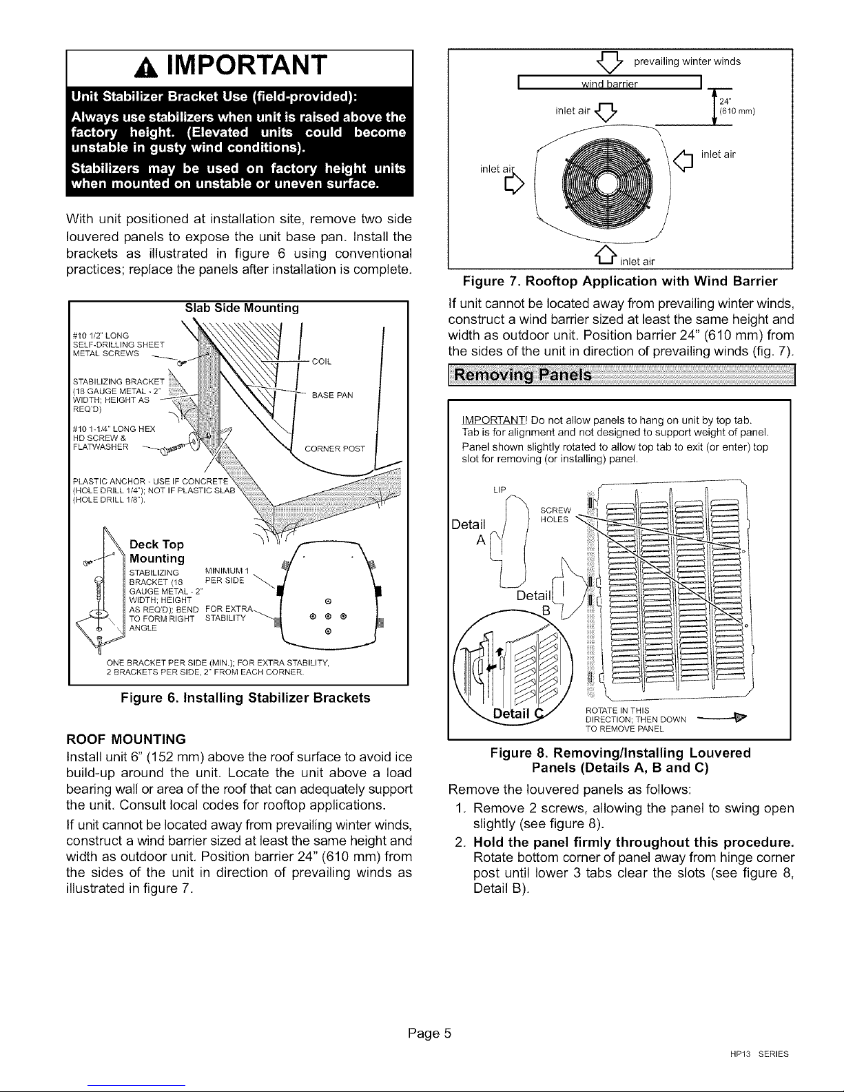
A IMPORTANT
®
Dallas, Texas, USA
WARNING
INSTRUCTIONS
HP13 Series Units
HEAT PUMP UNITS _Technical
505,076M LLJJ Publications
06107 LithoU.S.A.
Supersedes 07/06
HP13 Outdoor Unit ............................ 1
Shipping & Packing List ........................ 1
General Information ........................... 3
Unit Dimensions ............................... 2
Setting the Unit ............................... 3
Removing Panels ............................. 5
Electrical ..................................... 6
Refrigerant Piping ............................. 8
Refrigerant Metering Device .................... 10
Manifold Gauge Set ........................... 10
Service Valves ................................ 11
Leak Testing .................................. 11
Evacuation ................................... 12
Start-Up ...................................... 12
Refrigerant Charging ........................... 13
System Operation ............................. 15
Defrost System ............................... 15
Maintenance .................................. 16
Optional Accessories .......................... 16
Homeowner Information ........................ 17
Thermostat Operation .......................... 17
Start-Up and Performance Check List ............ 18
X_ IMPORTANT
06/07
IIIlllllllllllllllllllllllllllllllllllll
Lennox Elite ® Series HP13 outdoor units are approved
and warranted only for installation with specially
matched indoor coils, line sets, and refrigerant control
devices aC designated by Lennox. Refer to Lennox
engineering handbook for check expansion valve
(CTXV) kits which may need to be ordered separately.
1 - Assembled HP13 outdoor unit
Check unit for shipping damage. Consult last carrier
immediately if damage is found.
Page 1
505,076M
IIIllllllllllllllllllllllllllllllHlllllllll
TOP VIEW
4 C
DISCHARGE AIR t
f--
/
'X/
CONTACTOR
SUCTION LINE
CONNECTION FILTER DRIER/
CONNECTIONS
LIQUID LINE
CONNECTION
LIQUID LINE
CONNECTION
ELECTRICAL
/ INLETS
VAPOR LINE
JCONNECTION
RUN
CAPACITOR
DEFROST
BOARD
REVERSING
VALVE
LIQUID LINE
HP13 PARTS ARRANGEMENT
A
,OUTDOOR FAN
-COMPRESSOR
HIGH PRESSURE
SWITCH
(-018 MODEL ONLY)
, VAPOR LINE
VAPOR VALVE AND
- GAUGE PORT/SUCTION
LINE CONNECTIONS
q
UNIT SUPPORT
FEET
8-1/2
(2"
8-3/4
(2
HP13-018, -024, -030, AND -036
HP13 A
-018 35 (889)
-024 35 (889)
-030 31 (787)
-036 35 (889)
-042 35 (889)
-048 39 (991)
-060 39 (991)
SIDE VIEW
(343)
BASE SECTIONS
B
27 (686)
27 (686)
27 (686)
27 (686)
30-1/2 (775)
30-1/2 (775)
35-1/2 (902)
I I
C
28 (711)
28 (711)
28 (711)
28 (711)
35 (889)
35 (889)
39-1/2 (1003)
4-1/4 4-3/4
(108) (121)
f f
9-1/2
41)
8-1/4
(210)
l
D
13-7/8 (352) 7-3/4 (197)
16-7/8 (429) 8-3/4 (222)
E F
2(51) [_-
J
-
UNIT SUPPORT / "_
1 (25)
N
I I i i
SIDE VIEW
FEET\
D (_ @ C)
E
l
HP13 BASE WITH ELONGATED LEGS
G H J K
3-1/4 (83)
3-1/8 (79)
27-1/8 (689)
30-3/4 (781)
3-5/8 (92)
4-5/8 (117)
4-1/2 (114)
3-3/4 (95)
-r
K
_l
J
----I-
20-5/8 (524)
26-7/8 (683)
505076M 06/07
Page 2
WARNING
These instructions are intended as a general guide and do
not supersede national or local codes in any way.
Authorities having jurisdiction should be consulted before
installation+
When servicing or repairing HVAC components, ensure
the fasteners are appropriately tightened. Table 1 shows
torque values for fasteners+
Table 1. Torque Requirements
Parts Recommended Torque
Service valve cap 8 ft.- lb. 11 NM
Sheet metal screws 16 in.- lb. 2 NM
Machine screws #10 28 in.- lb. 3 NM
Compressor bolts 90 in.- lb. 10 NM
Gauge port seal cap 8 ft.- lb. 11 NM
CAUTION
position that will transmit sound or vibration to the
living area or adjacent buildings.
2+ Install the unit high enough above ground or roof to
allow adequate drainage of defrost water and prevent
ice build-up.
3+ In heavy snow areas, do not locate unit the where
snowdrifts will likely build. The unit base should be
elevated above the depth of average snows.
NOTE - Elevation of the unit may be accomplished by
constructing a frame using suitable materials. If a
support frame is constructed, it must not block drain
holes in unit base.
4+ Locate the unit so prevailing winter winds will not blow
into the coil.
5. Locate unit away from overhanging roof lines which
would allow water or ice to drop on, or in front of, coil
or into unit.
NOTES:
Service clearanceof30in. (762mm)mustbe maintainedon
oneof the sidesadjacentto the control box+
Clearanceto one of the otherthree sides must be 36 in. (914
mm)
Clearanceto one of the remainingtwo sides may be 12 in+(305
mm) and the final side may be 6 in. (152mm),
A clearanceof24 in, (610mm) must be maintained between
two units.
48 in. (1219mm)clearancerequired on top of unit,
Outdoor units operate under a wide range of weather
conditions; therefore, several factors must be considered
when positioning the outdoor unit+
Position the unit to allow adequate airflow and servicing
clearance. Maintain a minimum clearance of 24 inches
(610 mm) between multiple units as illustrated in figure 1+
1+ Place a sound-absorbing material, such as Isomode,
under the unit if it will be installed in a location or
Figure 1. Installation Clearances
SLAB MOUNTING
When installing unit at grade level, the top of the slab
should be high enough above grade so that water from
higher ground will not collect around the unit. The slab
should have a slope tolerance away from the building of 2
degrees or 2 inches per 5 feet (50 mm per 1500 mm) to
prevent ice build-up under the unit during a defrost cycle+
NOTE - If necessary for stability, anchor unit to slab as
described in "Stabilizing unit on uneven surfaces".
Page 3
HP13 SERIES
INSTALLUNITLEVELOR,IFONASLOPE,MAINTAINSLOPE
TOLERANCEOF2DEGREES(OR2INCHESPER5FEET
[50MMPER1.5M])AWAYFROMBUILDINGSTRUCTURE.
BUILDING
STRUCTURE
MOUNTING _ i T
SLAB
GROUND LEVEL
__L
Figure 2. Slab Mounting Options
ELEVATING THE UNIT (SMALL-BASE UNITS)
If additional elevation is necessary, raise the unit by
extending the length of the unit support feet. This may be
done by cutting four equal true-cut lengths of Schedule
(SCH) 40, 4" (101.6mm) piping to the height required as
illustrated in figure 3.
NOTE - Keep the height of extenders short enough to
ensure a sturdy installation. If it is necessary to extend
further, consider a different type of field-fabricated
framework that is sturdy enough for greater heights.
The inside diameter of the 4" (101.6mm) piping is
approximately 0.25" (6.35mm) greater than the
pre-installed feet on the unit. Devise a shim that will take up
the space and hold the extenders onto the feet during this
procedure. Small strips of 0.125" (3.175mm) thick
adhesive foam may be used. One or two small 1"
(25.4mm) square strips should be adequate to hold the
extender in place.
Base
Leg Detail
4" (101.6mm)
SCH 40 Piping
ELEVATING THE UNIT (LARGER-BASE UNITS)
Unlike the small-base units which use round feet, the
larger-base units are outfitted with elongated feet as
illustrated in figure 4. which uses a similar method for
elevating the unit height.
If additional elevation is necessary, raise the unit by
extending the length of the unit support feet. This may be
done with 2" SCH 40 female threaded adapter. The
specified coupling will fit snuggly into the recess portion of
the feet. Additional couplers can be used to make
additional adjustments to the level of the unit.
NOTE - Keep the height of extenders short enough to
ensure a sturdy installation. If it is necessary to extend
further, consider a different type of field-fabricated
framework that is sturdy enough for greater heights.
Base
Leg Detail
2" (50.8ram)
SCH 40
Female Threaded
Adapter
Figure 4. Elevated Slab Mounting using Feet
Extenders (Larger-Base Units)
STABILIZING UNIT ON UNEVEN SURFACES
To help stabilize an outdoor unit, some installations may
require strapping the unit to the pad using brackets and
anchors commonly available in the marketplace.
TYPICAL __,,,t
INSTALLATION
WITH 3 TO 4 IN.
EXTENDERS
IMPORTANT! STRUCTURE
INSTALLED _ BUILDING
ALWAYS USE MOUNTING _ i TSTABILIZER
BRACKET ON SLAB
ELEVATED
INSTALLATIONS
STABILIZER
BRACKETS
GROUNDLEVEL
Figure 3. Elevated Slab Mounting using Feet
Extenders (Small-Base Units)
505076M 06/07
Figure 5. Elevated Slab Mounting using Feet
Extenders
Page 4
IMPORTANT
With unit positioned at installation site, remove two side
Iouvered panels to expose the unit base pan. Install the
brackets as illustrated in figure 6 using conventional
practices; replace the panels after installation is complete.
Slab Side Mounting
prevailing winter winds
wind barrier ]
24"
inlet air ,_ _641'0 ram)
inlet air
inlet a[_
O inlet air
Figure 7. Rooftop Application with Wind Barrier
If unit cannot be located away from prevailing winter winds,
construct a wind barrier sized at least the same height and
width as outdoor unit. Position barrier 24" (610 mm) from
the sides of the unit in direction of prevailing winds (fig. 7).
IMPORTANT! Do not allow panels to hang on unit by top tab.
Tab is for alignment and not designed to support weight of panel,
Panel shown slightly rotated to allow top tab to exit (or enter) top
slot for removing (or installing) panel.
ONE BRACKET PER SIDE (MIN.); FOR EXTRA STABILITY,
2 BRACKETS PER SIDE, 2" FROM EACH CORNER.
Figure 6. Installing Stabilizer Brackets
ROOF MOUNTING
Install unit 6" (152 mm) above the roof surface to avoid ice
build-up around the unit. Locate the unit above a load
bearing wall or area of the roof that can adequately support
the unit, Consult local codes for rooftop applications.
If unit cannot be located away from prevailing winter winds,
construct a wind barrier sized at least the same height and
width as outdoor unit, Position barrier 24" (610 mm) from
the sides of the unit in direction of prevailing winds as
illustrated in figure 7,
LIP
SCREW
HOLES
Detail
J
ROTATE IN THIS
DIRECTION; THEN DOWN
TO REMOVE PANEL
Figure 8. Removing/Installing Louvered
Panels (Details A, B and C)
Remove the Iouvered panels as follows:
1, Remove 2 screws, allowing the panel to swing open
slightly (see figure 8).
2. Hold the panel firmly throughout this procedure.
Rotate bottom corner of panel away from hinge corner
post until lower 3 tabs clear the slots (see figure 8,
Detail B),
Page 5
HP13 SERIES
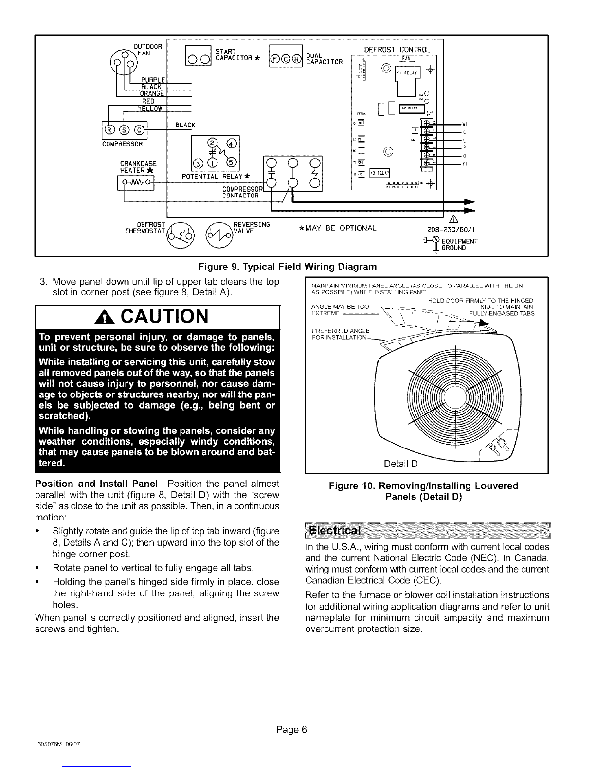
UTDOOR
FAN
PURPLE
BLACK
ORANGE
RED
CAPACITOR
START
DUAL
CAPACITOR
DEFROST CONTROL
,j! o +
BLACK
POTENTIAL _M_SOR (_
o_- ©
Y1ou_
--C
--L
--R
--0
--YI
COMPRESSOR
CRANKCASE
HEATER
LLOW
CONTACTORI / I
DEFROST.ff'"x _'\,REVERSING
THERMOSTAT_ _VALVE
*MAY BE OPTIONAL
Figure 9. Typical Field Wiring Diagram
3. Move panel down until lip of upper tab clears the top MAINTAINMINIMUMPANELANGLE(AS CLOSETOPARALLELWITHTHEUNIT
slot in corner post (see figure 8, Detail A). AS POSSIBLE) WHILEINSTALLINGPANEL.
ANGLE MAY BE TOO SIDE TO MAINTAIN
CAUTION
EXTREME _-_ FULLY-ENGAGED TABS
PREFERRED ANGLE
/k
20B-230/60/I
EQUIPMENT
GROUND
T
HOLD DOOR FIRMLY TO THE HINGED
Position and Install Panel--Position the panel almost
parallel with the unit (figure 8, Detail D) with the "screw
side" as close to the unit as possible, Then, in a continuous
motion:
• Slightly rotate and guide the lipof top tab inward (figure
8, Details A and C); then upward into the top slot of the
hinge corner post,
• Rotate panel to vertical to fully engage all tabs,
• Holding the panel's hinged side firmly in place, close
the right-hand side of the panel, aligning the screw
holes.
When panel is correctly positioned and aligned, insert the
screws and tighten,
505076M 06/07
Detail D
Figure 10. Removing/Installing Louvered
Panels (Detail D)
In the U.S.A., wiring must conform with current local codes
and the current National Electric Code (NEC). In Canada,
wiring must conform with current local codes and the current
Canadian Electrical Code (CEC).
Refer to the furnace or blower coil installation instructions
for additional wiring application diagrams and refer to unit
nameplate for minimum circuit ampacity and maximum
overcurrent protection size.
Page 6
 Loading...