

Page 1
E N G I N E E R I N G D A TA
I N D O O R A I R Q U A L I T Y
HCSTEAM
Healthy Climate
Residential Whole-Home Steam Humidier
Bulletin No. 210605
June 2011
®
MODEL NUMBER IDENTIFICATION
HCSTEAM - 16
®
HCSTEAM = Healthy Climate
Steam Humidier
FEATURES
WARRANTY
All covered components - limited ve-year warranty
in residential applications, one year in non-residential
applications.
Refer to the Lennox Equipment Limited Warranty
certicate included with the unit for additional details.
APPROVALS
All models are ETL/Intertek listed.
APPLICATIONS
The HCSteam humidier is designed to directly add
desired humidity levels to a duct distribution system for
improved comfort.
The humidier produces non-pressurized steam which
is then used to humidify the air.
Water quality can affect the operation of this unit, the
humidier water supply should be untreated potable
water, not softened or demineralized.
Unit Type
Nominal Capacity
16 = 15 US Gallons per day
35 = 35 US Gallons per day
The water converted into steam is automatically
replaced through an electric ll valve. Periodically,
based on the water quality, the unit will also drain and
add some water to dilute the build−up of minerals in the
Steam Generator Cylinder.
The humidier has been designed for installation on
a wall. Since it is an atmospheric steam humidier, it
should be placed close to the point where the steam
will be used to minimize the steam hose length and the
amount of condensate.
Included with the humidier:
• Steam nozzle
• Steam hose (10 ft.)
• Steam nozzle condensate drain hose (10 ft.)
• Water ll hose (6 ft.)
• Air proving pressure switch (required)
Page 2
FEATURES
I
J
C
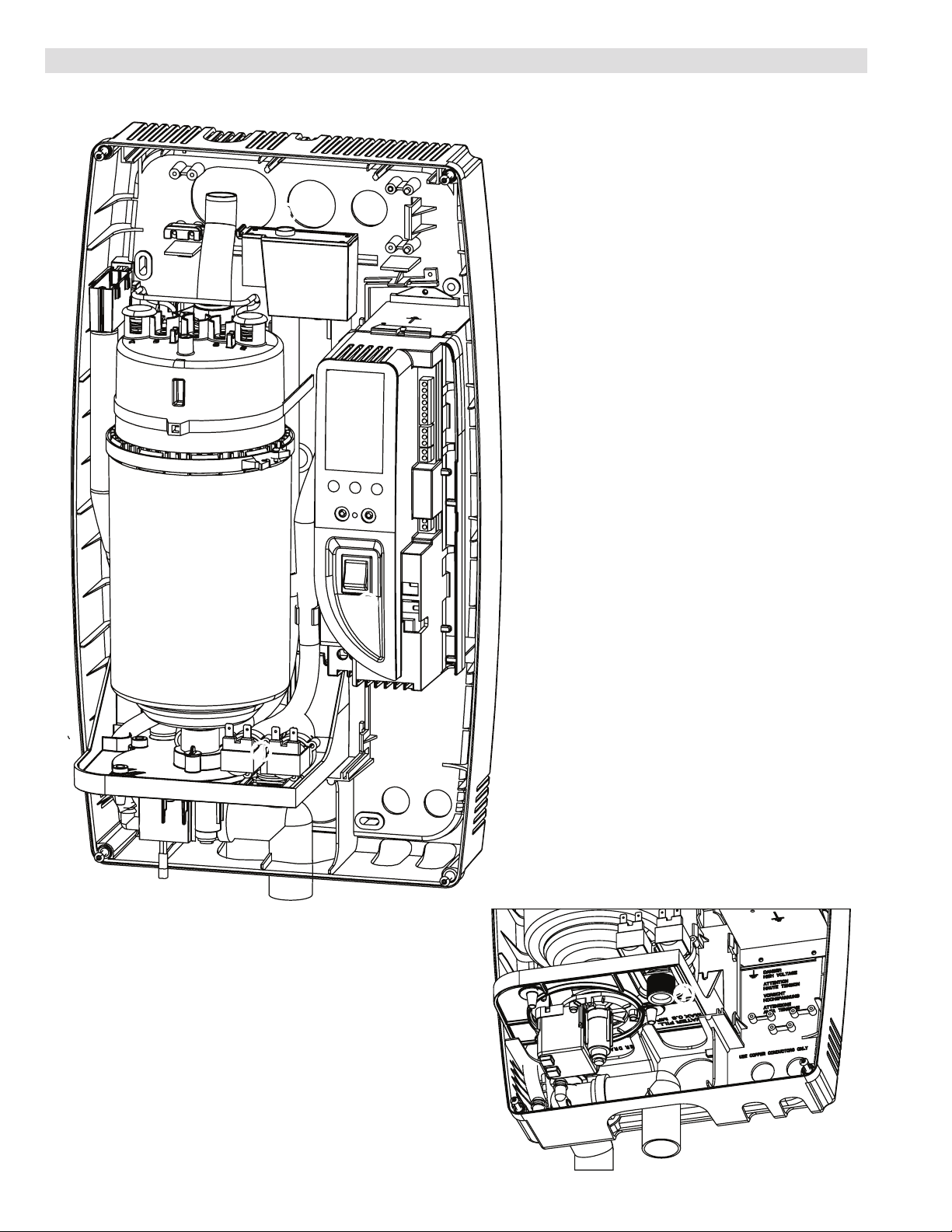
Steam Generator Cylinder
AB
Humidifier Controller
C
Power Button
D
Fill and Tempering Valves
E
Drain Pump
F
F
B
E
D
Water Drain
G
Water Inlet and Filter Screen
H
Steam Hose Connection
I
Condensate Drain Connection
J
H
HCSteam - Steam Humidier / Page 2
G
Page 3

FEATURES
INSTALLATION CONSIDERATIONS
This product must be installed by qualified HVAC and electrical contractors and in compliance with local, state,
and federal governing codes.
Humidifier is mounted on a wall and should be located close to the ductwork to minimize the length of the
steam hose for maximum performance.
The steam hose length between the humidifier and the ductwork varies depending on the type of installation.
See Installation Instructions.
Steam nozzle must be mounted in a supply duct. Nozzle must be installed downstream in a straight section of
duct with 3 ft. of straight metal ductwork free of elbows or obstructions.
The preferred installation for the steam hose and nozzle is higher than the humidifier for proper condensate
drainage.
Provisions to an open drain for periodic water draining from steam cylinder must be provided.
Air proving switch is required for proper operation and must be mounted close to the humidifier and ductwork
to ensure that the blower is operating prior to humidifier operation. Pressure tap must be installed in supply
duct. A second tap may be used in the return air duct for differential pressure applications.
Water for humidification should have the following characteristics:
• Water pressure between 20 and 110 psi
• Water temperature between 33 and 104°F
• Flow rate 0.21 GMP (minimum)
• Water hardness less than 400 ppm3 of calcium carbonate (CaCO3)
• Water conductivity from 125 to 1250 microsiemens per centimeter (μS/cm) for HCSteam-16
• 1 Water conductivity from 350 to 1250 microsiemens per centimeter (μS/cm) for HCSteam-35
• Absence of organic compounds
DO NOT use with softened water.
Refer to the Installation Instructions for detailed information.
Required Items
1/2 inch water line.
25 Amp dedicated electrical circuit.
1-1/4 inch drain tube extension (plumbed from the humidifier to an open drain, water drain receiver or a
condensate pump capable of holding one gallon of 140º F water then plumbed into a 3/4 inch drain line).
1
For HCSteam-35 model with low conductivity water conditions (125-350 μS/cm range) order optional Steam Generator Cylinder. See Optional Accessories.
Page 4
CYLINDER
STEAM
FEATURES
OUTLET
8
ELECTRODE
CYLINDER
STRAINER
7
STEAM
5
12
11
DRAIN
PUMP
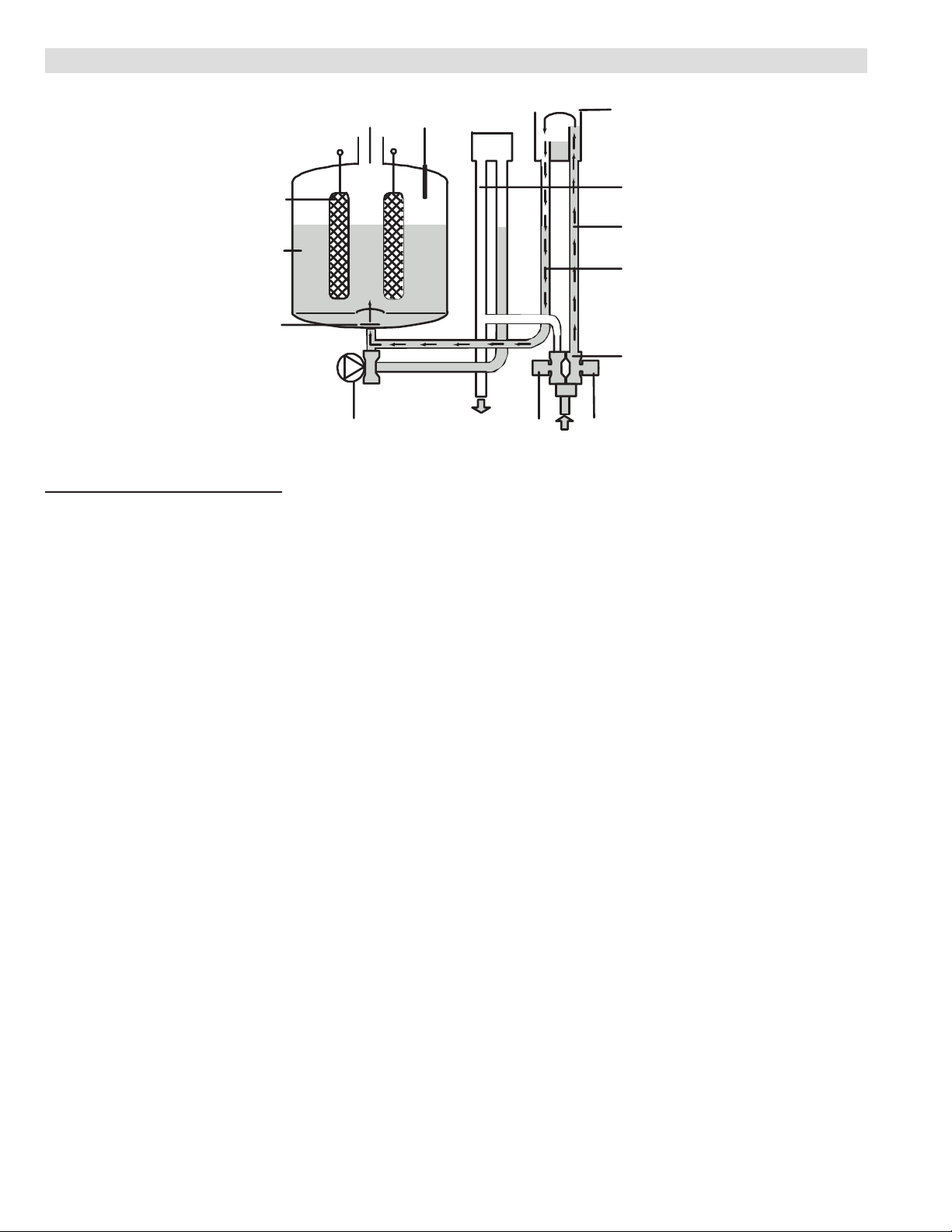
SEQUENCE OF OPERATION
The HCSteam steam humidier is an electrode
humidier. It produces steam for humidication by
passing electric current through metal electrodes (7)
immersed in water inside a plastic steam cylinder (5).
There are no heating elements.
Steam output is directly proportional to the conductivity
of the water, and the amount of electrode immersed in
the water.
On a call for humidity, the humidier controller will
open the water ll valve (1) and allow water to enter
the cylinder. A ow restrictor (4) prevents the unit from
lling too quickly or with too much pressure. Water
ows up the ll tube (2) and into the ll cup (3). Water
then ows over the dam in the ll cup (3), which creates
a 1-inch air gap to prevent backow of contaminated
water into the feed lines, it then ows through the ll
tube (6) and into the bottom of the steam cylinder (5).
Any backow or overow of water travels through the
overow hose (13) to the drain.
As the water lls the cylinder, it will reach the
electrodes (7) and current will begin to ow. As
the water continues to ll the cylinder, the current
will increase. This is monitored by an amperage
transformer connected to one of the power wires and
located on the electronic controller. When the desired
current is reached, the ll valve closes (1) and the
water will begin to warm and produce steam. If the
water reaches the cylinder full probe (9) or if current
rises too much, the drain pump (11) will be activated to
drain away excess water, reducing the water level in
the cylinder and reducing the current ow to acceptable
levels. Note that, any time the drain pump is activated,
the tempering valve (10) will be opened for tempering
the hot drained water down to 140ºF in accordance
with local and national standards.
FULL PROBE
9
HL
TEMPERING
Periodically, based on the incoming water conductivity,
the unit will run the drain pump (11) to drain and add
some water to reduce the mineral concentration. A lter
screen (12) in the cylinder helps to prevent mineral
debris from blocking the drain pump (11).
In case the humidier remains powered, but idle for
more than 48 hours (without producing steam), the
cylinder will automatically be emptied to eliminate
stagnant water inside.
If there is no water in the cylinder, there will be no
current ow and no steam production. The electrodes
do not burn out, but they will eventually become coated
with mineral deposits and the cylinder will require
replacement.
NOTE - Field installed air proving switch (furnished and
required) allows humidier to operate only when indoor
blower is operating.
VALVE
DT
10
3
FILL CUP
13
OVERFLOW
HOSE
2
FILL TUBE
6
FILL TUBE
4
FLOW
RESTRICTOR
1
FILL VALVE
HCSteam - Steam Humidier / Page 4
Page 5

FEATURES
HUMIDIFIER CONTROLLER
Microprocessor Humidity Controller automatically
manages all the functions of the unit, and includes a
self-diagnostic system with easy-to-read indicators
(numeric and icons). A comprehensive information
display shows the operation of the system at a glance.
1. Display is % of nominal
capacity
2. Maintenance or adjustment
3. Display is amperage
(default)
4. Steam is being produced
5. Cylinder filling
6. Foaming
7. Water presence inside
the cylinder
8. Cylinder draining
9. LED icons indicate: left:
operation (green);
middle: power (yellow);
right: alarms (red)
operation power alarm
10. Drain button for manual
draining of cylinder and
confirming parameter
values
11. ON/OFF button ("I" depressed is the ON posi-
OFF)
12. Reset button to reset
alarms and access parameters
13. Level of output: 33%,
66%, 100%
14. Fan relay is activated.
14
13
Controller Features
Controller features a eld programmable reduction in
maximum unit capacity (in 5% increments), allowing the
unit to adapt to the size of the area being humidied.
Includes an ON/OFF switch and a proportional input
function, a remote enabling input function for required
air proving switch (furnished), alarm relay contacts
for eld supplied alarm, ow sensor input and 24V
power supply output (for optional Healthy Climate
®
humidistat).
Ambient humidity control is managed by an external
humidistat (not furnished).
Steam production can be programmed for a specic
output capacity of 20% to 100% (in 5% increments).
Factory default settings:
HCSteam-16 - 100%, HCSteam-35 - 70%.
The optional Healthy Climate® Digital Automatic
Humidistat includes an on/off setting and a fully
proportional mode for steam output.
Water level is controlled by two valves (ll and
tempering) and the drain pump.
Automatic monitoring and ushing of the steam
generating cylinder is based on conductivity of the
electrode current draw.
Humidier automatically controls the amount of mineral
salts in the water by activating the ll valve and
drain pump. This reduces the amount of current ow
between the electrodes in the cylinder and eliminates
current leakage through the drain.
1
2
3
4
5
6
7
8
9
1012
Drain button allows manual drain/rell cycle for
maintenance.
Automatic monitoring and periodic drainage to handle
unacceptable water conditions.
Programmable to allow for a modulating hi-limit
humidity sensor or outdoor temperature sensor for
automatic trimming of the output to avoid condensation.
Hour counter keeps a record of operating hours and
has programmable maintenance alarm schedules.
Digital LCD Display
1. Instant current (default) / Steam production % /
Hour counter (hold Reset button to scroll values)
2. Active alarm
11
3. Electric current draw in amps
4. Steam production in progress
5. Cylinder lling in progress
6. Foam detected in cylinder
7. Water in cylinder
8. Cylinder drain in progress
Alarm and Pre-Alarm Functions
Controller panel has a green LED (operation), a
yellow LED (power) and a red alarm LED
LCD Display will show an error code related to the
following:
• Internal memory error
• Control board conguration not valid
• High current alarm
• Low production, low supply water conductivity or
excessive foam/lime scale in the Steam Generator
Cylinder
• Steam Generator Cylinder almost exhausted,
already used for 2000 hrs
• Fill alarm, unable or slow ll (current does not
increase within time-out)
• Drain alarm, unable to drain (current does not
decrease within time-out)
• Steam Generator Cylinder exhausted (critical
performance detected)
• Foam detected
• Steam Generator Cylinder lifetime expired (2000
hours)
• High controller temperature (above 176°F)
HCSteam - Steam Humidier / Page 5
Page 6

FEATURES
STEAM HEATING SYSTEM
Heating Electrodes
Designed for long life.
Immersion type.
Constructed of expanded low carbon steel, zinc-plated
and dynamically formed for precise current control.
Wiring to electrodes is secured by lock washer and nut.
Steam Generator Cylinder
Plastic cylinder is UL listed.
Single cylinder full electrode operates as an
independent circuit from the main power electrodes.
Full cylinder sensor detects foaming of the water and
end of cylinder life.
Power Drain Pump
Drain pump is used for ushing the system and for
maintaining proper water and current levels.
Pump drains water if there is excess water in the
steam generator cylinder and during steam generation
process to provide proper water level and minerals mix.
If the current generated in the water reaches excess
levels the humidier controller activates the drain pump
to drain a quantity of water to restore the current to
acceptable levels.
Tempering valve reduces the water temperature to
140°F before draining.
Drain connection can be from the bottom (vertical) or
rear (horizontal) of unit.
Anti-Foaming System
Automatic detection and correction of water foaming.
Steam Hose
Embedded steel spiral.
FDA approved (220°F, tested for 5000 hr).
Water Fill Hose
3/4 in. NPT female garden hose connection at each
end 90° angle on one end.
Air Proving Switch (Required)
Allows humidier to operate only when indoor blower is
operating.
Cabinet
Rugged, corrosion resistant molded plastic.
Removable front cover (4 Phillips head screws) for
easy access for servicing and maintenance.
OPTIONAL ACCESSORIES
icomfort Touch® Communicating Thermostat
(part of the icomfort™ Residential Communicating
Control System)
The icomfort Touch® Communicating Thermostat
recognizes and connects
to all icomfort™-enabled
products to automatically
congure and control the
system (based on userspecied settings) for the
highest level of comfort,
and performance. Also
recognizes model and serial
number information for icomfort™-enabled products to
simplify installation.
Large full color touchscreen - no hidden buttons or
doors.
A simple easy-to-use menu-driven touchscreen
allows complete system conguration. Scheduled
maintenance alerts, system warnings and
troubleshooting are also displayed in simple English on
thermostat screen.
Conventional products (not icomfort™-enabled) can
easily be added and controlled by the icomfort Touch®
Communicating Thermostat. NOTE - HCSteam
humidiers are not icomfort™-enabled.
(NOTE - An icomfort™-enabled indoor unit (furnace
or air handler) is required for proper operation with a
conventional outdoor unit.)
A tabbed interface lists all programming options on the
screen.
icomfort™-enabled Equipment (Indoor and Outdoor Units only)
Installer setup screens allow quick and simple system
conguration without a manual, Installer can also run
tests on complete system or individual components for
easy maintenance and troubleshooting.
Serial communications bus (RSBus), with less wiring
than a conventional heating/cooling system, allows
system communication. Uses 4-wire, 18-gauge
standard thermostat wiring.
See the icomfort Touch® Communicating Thermostat
Engineering Handbook bulletin in the Controls section
for more information.
HCSteam - Steam Humidier / Page 6
Page 7

FEATURES
INDOOR RH 26%
WED AN 21 12:35AM
MODE
ON
AUTO
HOME SCHEDULE OPTIONS
SETAT
SETAT
HEAT
COOL
SCHED
OPTIONAL ACCESSORIES (CONTINUED)
ComfortSense® 7000 Touchscreen Thermostat
Electronic 7-day, universal, multi-stage, programmable,
touchscreen thermostat.
4 Heat/2 Cool.
Auto-changeover.
Controls humidity during
cooling mode.
Offers enhanced
capabilities including
humidication /
dehumidication / dewpoint measurement and control,
Humiditrol® control, and equipment maintenance
reminders.
Easy-to-use, menu-driven thermostat with a back-lit,
LCD touchscreen.
Remote outdoor temperature sensor (optional)
allows the thermostat to display outdoor temperature.
Required in dual-fuel and Humiditrol® applications.
See the ComfortSense® 7000 Engineering Handbook
bulletin in the Controls section for more information.
Healthy Climate® Digital Automatic Humidistat
Basic humidity control (on/off or proportional) and
temperature display.
Control Buttons:
• Power button
• °F/°C display
• Set button for changing
humidity setpoints.
• SLEEP button for
changing day/night modes.
• PRG button for programming timed settings and
setting the clock.
• Up/Down buttons to change humidity setpoint and
time.
Built-in humidity sensor.
Outdoor temperature sensor furnished.
24VAC powered directly by the humidier.
LCD with alphanumeric characters and icon graphics
for Humidity and Temperature (indoor/outdoor),
Humidity Mode, Sleep Mode, Auto Mode, Lock Mode,
Program Timer On.
Large LCD display shows humidity (or temperature)
setpoint while the small display shows temperature (or
time) setpoint.
Built-in clock (with backup) for automatic humidity
control. Two time settings per day.
Error code display.
Lock mode indicates a parameter has been set.
Dimension (H x W x D): 3-3/8 x 5-1/2 x 1-3/8 in.
Healthy Climate® Water Conductivity Test Kit
A conductivity meter is recommended for testing the
water.
Measures total
dissolved solids
(TDS) and
temperature.
Automatic
Temperature Compensation (ATC).
Water-resistant housing
Measurement Range: 0-5000 ppm
Digital Calibration (Push button)
Auto-off function, data-hold function and low-battery
indicator.
Display: large and easy-to-read LCD screen includes
simultaneous temperature reading.
Factory-calibrated with a 342 ppm NaCl solution. The
meter can be recalibrated with digital calibration using
the Push buttons, rather than a screwdriver.
Includes cap and CR2032 battery.
Steam Generator Cylinder For Low Conductivity
Water (HCSteam-35 Model Only)
Normal water conductivity range is 350-1250 μS/cm.
For low conductivity water conditions (125-350 μS/cm
range) order optional Steam Generator Cylinder.
MAINTENANCE SUPPLIES
Replacement Steam Cylinders
Steam cylinders are available for annual
replacement (no more than 2500 operating hours).
HCSteam - Steam Humidier / Page 7
Page 8

SPECIFICATIONS
Model No. HCSteam-16 HCSteam-35
Performance Duct Steam Injection US gallons per day 15 35
lbs. per hour 5.5 12
Steam pressure 3.81 in. wg 3.81 in. wg
Input Water Type Potable water Potable water
Conductivity Range 125-1250 μS/cm
Ambient
Conditions
Storage
Conditions
Operating Temperature 34°F to 104°F 34°F to 104°F
Operating Humidity 10 to 60% RH 10 to 60% RH
Temperature Storage 14°F to 158°F 14°F to 158°F
Humidity Storage 5 to 95% RH 5 to 95% RH
Connections Water ll connection 3/4 in. NPT 3/4 in. NPT
Drain connection 1.25 in. OD 1.25 in. OD
Steam Hose 1-1/4 OD, 7/8 in. ID 1-1/4 OD, 7/8 in. ID
Drain Water Temperature < 140°F < 140°F
Drain Pump Flow 2.16 US GPM 2.16 US GPM
Weight Data lbs.
Shipping 22 22
Empty 18 18
Installed with water 26 26
1
350-1250 μS/cm
ELECTRICAL DATA
Voltage 115/120V-1ph 220/240V-1ph
Amps 16.40 16.95
Maximum overcurrent protection 25 25
Power relays (amps) (2) 20 (2) 20
Ground connection Wire Nut Wire Nut
Electrode power cables 10 AWG 10 AWG
OPTIONAL ACCESSORIES
icomfort Touch® Communicating Thermostat 49W95 49W95
2
Remote Outdoor Temperature Sensor
X2658 X2658
(for dual fuel, Humiditrol® and outdoor temperature display)
3
Discharge Temperature Sensor 88K38 88K38
ComfortSense
4
Remote Outdoor Temperature Sensor
®
7000 Thermostat Y2081 Y2081
X2658 X2658
(for dual fuel and Humiditrol)
Healthy Climate
Healthy Climate
1
Steam Generator Cylinder for Low Conductivity Water (below 350 μS/cm) - - - Y3484
®
Digital Automatic Humidistat Y3760 Y3760
®
Water Conductivity Test Kit Y3480 Y3480
MAINTENANCE SUPPLIES
Replacement Steam Generator Cylinders Y3481 Y3482
For HCSteam-35 (low conductivity water models) - - - Y3484
1
For low water conductivity conditions (125-350 μS/cm range) order optional Steam Generator Cylinder for Low Conductivity Water (Y3484).
2
Remote Outdoor Sensor may be used with an icomfort®-enabled outdoor unit for a secondary (alternate) sensor reading. Sensor may also be used with a conventional
outdoor unit.
3
Optional for service diagnostics.
4
Remote Outdoor Temperature Sensor for ComfortSense 7000 Thermostat must be connected directly to the thermostat.
HCSteam - Steam Humidier / Page 8
Page 9

HUMIDIFICATION LOAD REQUIRED - GALLONS PER DAY
(Reference: AHRI Guideline F-2008)
Type of
Construction
8000 10,000 12,000 16,000 20,000 24,000 32,000 40,000
Volume of Building ft
Tight 4.3 5.3 6.4 8.5 10.6 12.7 17.0 21.2
Average 8.6 10.6 12.8 17.0 21.3 25.4 34.0 42.6
Loose 12.7 15.9 19.1 25.5 31.8 38.1 51.0 63.6
Legend: HCSteam-16
HCSteam-35
Exceeds capacity of one HCSteam unit
NOTES - Tight = 1/2 air change per hour.
Average = 1 air change per hour.
Loose = 1-1/2 air changes per hour.
3
(approximate)
HCSteam - Steam Humidier / Page 9
Page 10

DIMENSIONS - INCHES (MM)
17-5/8
(448)
13-7/16
5
(128)
MOUNTING
HOLES
(341)
10-1/8
(257)
C L
5
(128)
8
(204)
1-5/8
(40)
7/8
2-3/8
(24)
(60)
STEAM
2-1/8
STEAM
2-3/4
(70)
(54)
2-1/2
(65)
C L
CONDENSATE
3/8
(9)
1-7/8
2-3/4
(48)
(70)
1-1/8 dia. (30)
1-5/8 dia. (40)
CONDENSATE
(600)
23-5/8
2 dia. (51) 7/8 dia. (23)
2-3/8"
(60)
DRAIN
2
(51)
1-1/2
(38)
2-3/8
(60)
3-7/8
(98)
5/8 (16)
3-5/8
(92)
DRAIN
4
(102)
INSTALLATION CLEARANCES - INCHES
Top 6 in.
3-7/8
(98)
ELECTRICAL
FILL
3-1/4
(82)
3-1/8
(78)
FILL
1-3/8
(35)
1-1/2
2-1/8
(37)
(53)
ELECTRICAL
1-3/8
(36)
2-1/2
(62)
Bottom 6 in.
Left Side 6 in.
Right Side 6 in.
Front 24 in.
Page 11

Page 12

REVISIONS
Sections Description of Change
Maintenance Supplies New Section - Added replacement steam cylinders.
Visit us at www.lennox.com
For the latest technical information, www.lennoxdavenet.com
Contact us at 1-800-4-LENNOX
NOTE - Due to Lennox’ ongoing commitment to quality, Specications, Ratings and Dimensions subject to change without notice and without incurring liability.
Improper installation, adjustment, alteration, service or maintenance can cause property damage or personal injury.
Installation and service must be performed by a qualied installer and servicing agency. ©2011 Lennox Industries, Inc.
 Loading...