

Page 1

INSTALLATION
INSTRUCTIONS
E2011 Lennox Industries Inc.
Dallas, Texas, USA
Table of Contents
GENERAL
Introduction 2. . . . . . . . . . . . . . . . . . . . . . . . . . . . . . . . . . . . . . . .
Optional Dehumidification Accessories 2. . . . . . . . . . . . . . . .
Residential Zone Control System − Field Wiring 3. . . . . . . . .
System Components (included & separately ordered) 4. . . .
Installation planning & selecting heat/cool equipment 5. . . .
Installing Zone Control Components 6. . . . . . . . . . . . . . . . . . .
Zone Control Panel Jumpers:
General Information 8
Air Reduction 9
Air Reduction 9
Heat/Cool Staging 10
SYSTEM Configuration/E−Heat Stages 11
Common System Component Wiring 12. . . . . . . . . . . . . . . . . .
Zone Control Transformer Phasing 13. . . . . . . . . . . . . . . . . . . .
Component Specific Wiring 13. . . . . . . . . . . . . . . . . . . . . . . . . .
Minimum CFM in Variable Speed Furnaces 14. . . . . . . . . . . . .
System Flow Diagrams 15. . . . . . . . . . . . . . . . . . . . . . . . . . . . . .
HEAT PUMP
Installing Heat Pump and accessories 16. . . . . . . . . . . . . . . . .
Zone control system wiringHeat Pump 17. . . . . . . . . . . . . . .
Heat Pump System Startup and Checkout 18. . . . . . . . . . . . . .
Heat Pump Heating Checkout − Single Zone 18
Heat Pump Heating Checkout − Multiple Zone 19
Heat Pump Heating Checkout − Central Control 19
Heat Pump Pressure Switch Checkout 20
Troubleshooting:
Zoning system with Heat Pump 21. . . . . . . . . . . . . . . . . . . .
HP Heating Operation 22
Defrost Operation 23
GAS FURNACE
Zone control system wiringGas Furnace 24. . . . . . . . . . . . .
G71MPP/SLP98/SL280V/EL296V:
Integrated Control Electrical Adjustments 25
System operation 26
Installation setup worksheet 27
G61MPV/G60UHV:
Integrated Control Electrical Adjustments 28. . . . . . . . . . . .
System Operation 30
Installation setup worksheet 32
. . . . . . . . . . . . . . . . . . . . . . . . . . . . . .
. . . . . . . . . . . . . . . . . . . . . . . . . . . . . . . . . . .
. . . . . . . . . . . . . . . . . . . . . . . . . . . . . . . . . . .
. . . . . . . . . . . . . . . . . . . . . . . . . . . . . . . .
. . . . . . . . . . . . .
. . . . . . . . .
. . . . . . . .
. . . . . . .
. . . . . . . . . . . . . .
. . . . . . . . . . . . . . . . . . . . . . . . . . . .
. . . . . . . . . . . . . . . . . . . . . . . . . . . . . . . .
. . . . . . . . . . . .
. . . . . . . . . . . . . . . . . . . . . . . . . . . . . . . .
. . . . . . . . . . . . . . . . . . . . . . .
. . . . . . . . . . . . . . . . . . . . . . . . . . . . . . . .
. . . . . . . . . . . . . . . . . . . . . . .
Harmony IIIt Zoning System
ZONING
505,023M
08/11
Supersedes 01/11
Litho U.S.A.
Retain These Instructions For Future Reference
IMPORTANT
Variable Speed Blower Motor (VSM) technology is
required for use with Lennox Harmony IIIt Zone
Control Systems.
Only technicians qualified for zoning installations
should perform the equipment setup in this manual.
Gas Furnace Start−Up & Checkout:
Gas Heating Checkout − Single Zone 33. . . . . . . . . . . . . . .
Gas Heating Checkout − Multiple Zone 34
Gas Heating Checkout − Central Control 34
Troubleshooting:
Zoning system with Gas Furnace 35
Gas Heating Operation 36
Discharge Air Upper Limit & Differential Temp. 37
. . . . . . . . . . . . . . . . . . . . . . . . . . .
AIR HANDLERS
Variations on common condensing unit applications:
Electric Heat, Hot Water Coil, Cooling Only 38. . . . . . . . . .
Air Handler Settings (All applicable models) 39. . . . . . . . . . . .
Installation Setup Worksheets:
CBX32MV/CBX40UHVCooling/Heating; Electric
Strip Heat (non−HP appls) 40. . . . . . . . . . . . . . . . . . . . . . . . .
CBX32MV/CBX40UHVHeat Pump; Electric Strip Heat 41
CBX32MV/CBX40UHV – Cooling Only or Cooling
with Hot Water Coil (non−HP appls) 42. . . . . . . . . . . . . . . . .
DUAL FUEL
Zone control system wiringDual Fuel 43. . . . . . . . . . . . . . . .
Dual Fuel Startup & Checklist 44. . . . . . . . . . . . . . . . . . . . . . . .
Gas Heating Checkout − Single Zone 44. . . . . . . . . . . . . . .
Gas Heating Checkout − Multiple Zone 45
Gas Heating Checkout − Central Control 46
Troubleshooting:
Zoning system with Dual Fuel 47
Dual Fuel Operation (Below Balance Point) 48
Discharge Air Upper Limit & Differential Temperatures 49
Dual Fuel Operation (Above Balance Point) 50
Defrost Operation 51
Installation Setup Worksheets:
G61MPV/G60UHV Dual Fuel; with
Honeywell 2−stage IFC control (HP appls) 52. . . . . . . . . . .
G71MPP/SLP98/SL28V0/EL296V Dual Fuel (HP appls) 53
. . . . . . . . . . . . . . . . . . . . . . . . . . . . . . . .
. . . . . . . . . . . . . . . . . . . . . .
TROUBLESHOOTING
Operation & Troubleshooting Indicators 54. . . . . . . . . . . . . . . .
Fault Recall. Time Delays, Time Delay Override 55. . . . . . . . .
Diagnostics Codes 56. . . . . . . . . . . . . . . . . . . . . . . . . . . . . . . . . .
Troubleshooting Air Delivered by Blower 58. . . . . . . . . . . . . . .
PIAB Calculation Worksheet 60. . . . . . . . . . . . . . . . . . . . . . . . .
. . . . . . . . . . . . . .
. . . . . . . . . . . . .
. . . . . . . . . . . . . . . . . . .
. . . . . . .
. . . . . . . . . . . . . .
. . . . . . . . . . . . .
. . . . . . . . . .
.
. . . . . . . . . .
08/11 505,023M (#10009243)
*2P0811* *P505023M*
Page 1
Page 2

GENERAL
GENERAL
Shipping & Packing List
Items shipped with the Harmony IIIt Zone Control System
include:
1 − Harmony IIIt Zone Control System unit
1 − Discharge Air Sensor
Additional itemsordered separately; include (see System Components on Page 4):
S Transformer
S Dampers
S Thermostats
S Balance Point Sensor kit (56A87)
S Pressureswitch (For Heat Pump Option):
HFC−22 (27W12); HFC−410A (27W13)
S Tee for vapor line High Pressure Switch (87071)
S Defrost Tempering Kit (67M41)
S Humiditrol
EDA−024B (94M41), EDA−036C (94M42), EDA−060D
(94M43)
S Humiditrol
if Humiditrol
®
Enhanced Dehumidification Accessory (EDA),
®
Zoning Accessory (HZA) Kit (39W67) (required
®
EDA, above, is used)
Introduction
The Lennox Harmony IIIt Zone Control System manages
the distribution of conditioned air to specific areas or zones
in a house or small commercial building by directing heated
or cooled air to occupied areas without conditioning unused areas. This improves economy while providing a balanced and comfortable environment. The system can be
used in the following Lennox HVAC system applications:
Option 1.Variable speed gas furnace used with a 2-stage
condensing unit.*
Option 2.Variable speed air handler unit (with or without
electric heat) used with a 2-stage condensing
unit or heat pump.*
Option 3.Variable speed gas furnace used with a 2-stage
heat pump.*
*A 1 stage condensing unit (heat pump) may be used under specific
circumstances as listed in Table 3 (see Page 5).
Variations on the options described above and included in
this document are: cooling−only, hot water coil, and cooling
system with electric heat applications.
The Harmony IIIt zone control system uses off−the−shelf,
single-stage, non-heat pump, non−power-robbing electronic thermostats and motorized dampers in any of the applications to control distribution of conditioned air to different zones. This control allows conditioning of different
zones within a residence while using a single HVAC system.
The zone control system operates in two modes: central
control (vacation mode) or zone control. LEDs on the
zone control panel indicate the current operating mode.
When the system is in the central control mode, a de-
mand from the central control thermostat results in conditioned air being directed to all of the zones. In this mode,
zone 1 thermostat is designated as the controlling thermostat; other thermostats are not used.
When the system is in the zone control mode, a zone is
conditioned only upon demand from that zone’s thermostat.
The zone control system is ideal for retrofit applications as
well as new construction. The system controls the air volume, eliminating the need for bypass dampers in most applications. The homeowner controls the system using
zone thermostats to make comfort settings for each zone.
A programmable thermostat should be used to provide a
specialized heating and cooling sequence. While the system is in the zone mode, a programmable thermostat controls the temperature for its particular zone.
Optional Dehumidification Accessories
The Harmony IIIt zone control system may be used in conjunction with a Humiditrol® Enhanced Dehumidification Accessory (EDA) and which also requires a Humiditrol® Zoning Accessory (HZA). This document reflects the control
which is outfitted for connection to, and control of, the EDA
in a zone control system using the HZA. See Humiditrol
Zoning Accessory Installation Instructions for more information.
®
505023M 08/11
Page 2
Page 3

Residential Zone Control System − Overview of Field Wiring
THERMOSTAT (ZONE 1 OR CENTRAL CONTROL
THERMOSTAT WHEN IN VACATION MODE)
ZONE 1
A
GENERAL
ZONE 2
A
THERMOSTAT
(ZONE)
ZONE DAMPER
POWER
HUMIDITROL® ENHANCED
DEHUMIDIFICATION
ACCESSORY
OPTIONAL
TRANSFORMER TO POWER
ZONE CONTROL PANEL, THER-
MOSTATS AND DAMPERS;
ALSO POWERS HZA CONTROL
WHEN EDA IS USED)
HUMIDITROL
ZONING
ACCESSORY (HZA)
THERMOSTAT
(ZONE)
ZONE DAMPER
*ZONE 3
B
®
H
LEGEND −
A Five wire low voltage 18 ga. minimum
B Two wire low voltage OR Three wire if Power−open, Power−closed 18 ga. minimum
C INDOOR UNIT: Up to nine wire low voltage 18 ga. minimum
D OUTDOOR UNIT:
− Two (3, if LSOM equipped unit) wire low voltage (single-stage condensing unit or EDA) 18 ga. minimum
− Three (4, if LSOM equipped unit) wire low voltage (two-stage condensing unit) 18 ga. minimum
− Up to seven wire low voltage (single-stage heat pump outdoor unit) 18 ga. minimum
− Up to eight wire low voltage (two-stage heat pump outdoor unit) 18 ga. minimum
E Two wire low voltage (discharge air sensor) 18 ga. minimum
F Two wire low voltage (pressure switch, heat pump only) 18 ga. minimum
G Two wire 18 ga. minimum
H Refer to the Humiditrol® Zoning Accessory (HZA) for wiring requirements.
B
ZONE CONTROL
SYSTEM PANEL
A
B
B
D
E
A
B
G
*NOTE − Zone 3 and zone 4 not available with single-stage outdoor unit.
F
C
*ZONE 4
ZONE DAMPER
CONDENSING
UNIT OR HEAT
PUMP OUTDOOR UNIT
DISCHARGE
AIR SENSOR
VARIABLE SPEED
FURNACE OR AIR
HANDLER
THERMOSTAT
(ZONE)
ZONE DAMPER
OUTDOOR
THERMOSTAT /
BALANCE
POINT SENSOR
Page 3
HARMONY IIIT ZONE CONTROL SYSTEM
Page 4

GENERAL
System Components
The Harmony IIIt zone control system consists of the following (n − required):
n Harmony Harmony IIIt zone control panel (included)
n Discharge Air sensor (included)
n Thermostats (1 for each zone; ordered separately)
n 24VAC Power Transformer(s) (ordered separately)
n Dampers (ordered separately)
n Pressure Switch and Tee w/Schrader valve (for Heat Pump
systems; ordered separately)
S Balance Point Sensor (Optional for Dual Fuel systems)
S Defrost Tempering Kit (Optional for Dual Fuel systems)
S Remote Vacation Switch (optional; ordered separately)
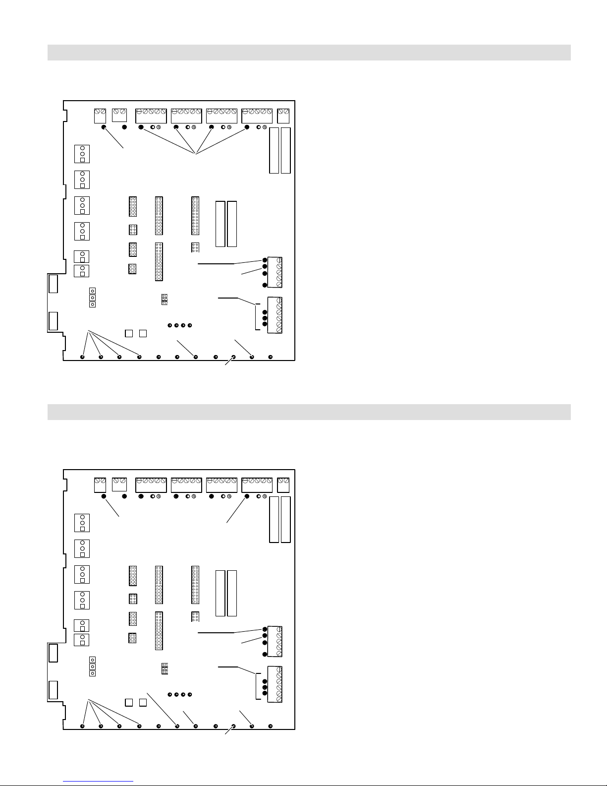
Zone Control System
The Harmony IIIt zone control system monitors electrical
signals and directs control signals between thermostats,
dampers, and HVAC equipment (see figure 1).
DAMPER
CONNECTIONS
Figure 1. Harmony IIIt Zone Control Panel
Discharge Air Sensor (DAS)
A discharge air temperature sensor (88K38) monitors the
supply air. This electronic sensor’s probe is inserted into
the discharge air plenum to gather air temperature data for
the zone control panel. Figure 2 shows the kit; see figure 3
(Page 6) for location of the sensor.
TEMPERATURE/RESISTANCE CHART
TEMP ºF RESISTANCE (OHMS)
PRESSURE
SWITCH CONNECTIONS
REDUCTION
REMOTE
VACATION
SWITCH;
CONNECTIONS
FOR HZA
30 34,566
40 26,106
50 19,904
60 15,313
70 11.884
80 9,298
90 7,332
100 5,826
JUMPERS:
STAGING
TEMP‘
HEATING−−
COOLING−−
AIR
CONT.−−
HEATING−−
DISCHARGE
AIR SENSOR
CONNECTIONS
TIME
DELAY
OVER-
RIDE
SYSTEM OPERATION LEDS
THERMOSTAT
CONNECTIONS
OUTDOOR THERMOSTAT /
BALANCE POINT SENSOR
CONNECTIONS
PIAB
JUMPERS
SYS CONFIG &
E−HEAT JUMPERS
FAULT
RECALL
DIAGNOSTIC
LEDS
Figure 2. Discharge Air Sensor
24VAC
CONNECTIONS
FUSES
EQUIPMENT
CONNECTIONS
Thermostats
IMPORTANT
Use only Electronic thermostats. Mechanical or
electro-mechanical thermostats will not work with
the Harmony IIIt zone control system.
For all zones, use thermostats that are of this type:
S electronic thermostat
S single-stage
S non-heat pump
S non-power robbing
S autochangeover or non−autochangeover
S Lennox recommends that zone 1 thermostat (central [vaca-
tion] mode controller) be programmable.
S Each thermostat must have a deadband between HEAT and
COOL.
Recommended thermostats include:
S ComfortSenset 7000 model L7742U Touch Screen Ther-
mostat. (IMPORTANT! When using this thermostat, only
Precision Mode dehumidification can be used wherein 2°F
of over-cooling is allowed. Also, it cannot reduce the blower
speed because the zone control DS signal controls the blower. Thermostat D terminal is not used.
S ComfortSenset 5000 model L5711U Touch Screen Ther-
mostat − 1 heat / 1 cool / 7−day programmable.
Transformer
The dampers, zone control panel, zone thermostats and
Humiditrol® Zoning Accessory (if EDA is used) are powered by a single, field−provided 24VAC transformer. Together, the zone control panel and thermostats require
10VA; dampers require 10VA each. The transformer must
have an adequate VA rating to serve all components (see
recommendations in table 1).
IMPORTANT
Up to 5 dampers per zone may be connected in parallel to the zone control panel not to exceed a total
of six dampers for entire system.
Also, if more than 6 dampers are used, another
transformer and isolation relay will be necessary.
Table 1. 24VAC Transformer selection chart
Catalog
Number
10P17 40VA 120/208/240VAC, 24VAC 3 dampers
10P87 50VA 120/208/240VAC, 24VAC 4 dampers
12P61 75VA 120/208/240VAC, 24VAC 6 dampers
83P74 _ Electrical Box (4-in. square)
Size Description
VA LOAD =
Panel plus−
505023M 08/11
Page 4
Page 5

System Components (Continued)
Dampers
Motorized 24VAC powered closed/spring return open
dampers are standard for the Harmony IIIt zone control
system. However, power-open/spring-close" and poweropen/power-close" dampers can be accommodated.
Remote Vacation Switch
The Harmony IIIt zone control panel includes connections for an optional remote vacation switch (see figure 1).
The same connections are also used for connecting an op-
tional Humiditrol
®
Zoning Accessory Installation Instructions for de-
ditrol
tails).
NOTE − If a remote vacation switch is connected for
routing to a convenient location for end user operation, be sure the switch (field-provided) is properly labeled and instructions provided for proper operation.
DO NOT LOCATE THE REMOTE VACATION SWITCH
NEXT TO OTHER HOUSE SWITCHES! THE RECOMMENDED LOCATION IS NEXT TO ZONE 1 THERMOSTAT.
®
Zoning Accessory controller (see Humi-
Installation planning & selecting heating and cooling equipment
GENERAL
Installation Considerations
The total HVAC system must be properly sized to provide
the best comfort. Also, for best performance, zones should
be similar in size so that each zone would require about the
same CFM. Each zone’s ducting lengths should be similar
in length whenever possible. Always attempt to keep CFM
requirements per zone within 25% of the average CFM
(see table 2).
If a small" zone cannot be avoided, give consideration to
increasing the CFM of the small zone and linking a damper
in a nearby zone that will open along with the small zone’s
damper(s). The procedure for zone linking is described on
Page 7.
Table 2. Adjusting for average CFM Example
Required CFM CFM adjusted to within average
Zn CFM Avg %CFM Adj Avg %CFM
1 500
2 825 1.16 825 1.12
3 775 1.09 775 1.05
4 750 1.05 750 1.02
713
0.70 600
738
0.81
Damper linked
with Zn 2
Variable Speed Blower Motor (VSM)
Indoor units with variable speed blower motors (VSM) are
required to allow the zone control system to distribute adequate air to each zone. Use only units recommended in
the following 3 options as only those will work with the
Harmony IIIt zone control system; other types of units will
not allow the Harmony IIIt zone control system to propor-
tion the amount of air going to each zone.
Selecting/Installing Indoor and Outdoor Units
Outdoor units may be single or two−stage; use table 3 to
determine which to use, based on the number of zones being implemented, and whether the air conditioned zones
are of equal or unequal size.
Option 1
Lennox Gas Furnace with VSM only (G60UHV, G61MPV,
S
G71MPP, SLP98, SL280V, E296V).
S Lennox Condensing Unitas described in table 3.
Option 2
Lennox Air Handler Unit with VSM only (CBX32MV,
S
CBX40UHV, CB31MV, CBWMV).
S Lennox Heat Pump Unitas described in table 3.
Option 3
Lennox Gas Furnace with VSM only (G60UHV, G61MPV
S
G71MPP, SLP98, SL280V, E296V).
S Lennox Heat Pump Unit as described in table 3.
NOTE − Limited variations to condensing units described
herein are detailed on Page 38.
Table 3. Condensing units / Heat Pump units
No. of
zones
2 *Equal Single or Two−stage
2 *Unequal Two-stage only
3 or 4 Equal or Unequal Two-stage only
*Equal zones would have very similar total ducting lengths with CFM
requirements within 10% of average CFM per zone. Unequal would
have less similar ducting length and greater variances from average
CFM (see table 2 example).
Comparative Zone
sizes
Lennox Condensing Unit or
Heat Pump
Page 5
HARMONY IIIT ZONE CONTROL SYSTEM
Page 6

GENERAL
Installing Zone Control Components
When possible, position the sensor some distance away from the coil rather than in the immediate coil area. The Discharge Air Temperature
Sensor should be located at least 10 inches
above the coil.
Fasten the sensor bracket to the plenum
with two self- tapping sheet metal screws.
Connect wires to DAS on zone
control panel, NOT on the AHC or
IFC (see figures 17 through 26).
Be sure that the tip of the sensor is located
approximately 10 inches from the indoor coil in
the discharge plenum, and 1/2 the depth of the
plenum, and centered over the discharge airflow,
side-to-side.
PLENUM
1/2
the width
of the
plenum
SENSOR
MOUNTING
DETAIL
Figure 3. Discharge Air Temperature Sensor installation (Typical Upflow Furnace)
Zone Control Panel
IMPORTANT
The electrical power source for the zone control system, i.e. the transformer primary, and furnace or air
handler unit must be the same source. In addition,
the zone control system power−up must occur at the
same time or before the furnace or air handler unit
is powered up.
Select an installation site for the Harmony IIIt control con-
sidering the following location parameters:
S Is conveniently accessible and centrally located to facilitate
wiring from thermostats, dampers, pressure switch (if used),
and HVAC equipment.
S Is in a non−condensing area (such as a closet).
S Is NOT in a laundry room (nor other room in the house where
the humidity would typically be much higher than the rest of
the house).
S Is NOT in any part of the building where the temperature may
exceed 150_F.
NOTE 1 − FOR UNITS WITH HUMIDITROLDischarge air sensor
(DAS) MUST be located on the output side of the EDA (if used; see
Humiditrol Zoning Accessory Installation 505,337M)
19
(254)
AIR HANDLER
SIDE VIEW
sensor centered in
discharge airflow
(ALSO see note 1)
SENSOR PROBE
see PROBE
MOUNTING
DETAIL below
ECB
Electric
Heat
Strips
FURNACE
FRONT
VIEW
plenum
coil
Discharge Air Sensor
CAUTION
This device is manufactured using unpainted and
pre-painted metal. Sharp sheet metal edges can
cause injury. When installing the device, avoid accidental contact with sharp edges.
Install the discharge air sensor in the discharge plenum
downstream from the cooling coil. Be sure that the discharge air will pass over the sensor before the air is distributed into the duct system. Typical upflow sensor applications are shown in figure 3; the sensor dimensions shown
(distance from heat strips, coil, and position in plenum)
also apply to other applications.
505023M 08/11
Page 6
Page 7

Thermostats
Identify the best location for a thermostat in each zone. If
two or more rooms are within a single zone, place the thermostat in a location that is central to all rooms. For example, if a zone contains two bedrooms, try to place the thermostat in a hallway near both bedrooms.
Do not install thermostats in drafty areas, behind doors, in
corners, near radiant heat sources (appliances), near
sunny windows, near concealed pipes and chimneys, nor
in unconditioned spaces such as closets or exterior walls.
Transformer
Obtain an appropriately−rated transformer (see table 1,
Page 4). Install the transformer in either the indoor unit or
in an electrical junction box near the zone control panel.
Dampers
NOTE − The power source for the transformer must be the
same power source as the indoor unit’s transformer.
Motorized dampers in the supply duct system regulate air
to the zones. Some applications will be unique and require
more than one damper per zone. If additional dampers are
required, refer to the the wiring diagram in the Common
System Component Wiring section (page 12). Also, if more
than 6 dampers are used, another transformer and isolation relay will be necessary.
For more effective zone isolation, the return duct system
may also be dampered by zone. Dampers for each zone
must be wired in parallel. Install dampers in the desired
locations; then run thermostat wire from the damper to the
zone control panel and damper relays as needed.
Zone LinkingZone link a small zone to a large zone by
wiring dampers in a manner similar to figure 4. Effectively,
this distributes some of the small zone’s air to another
zone to reduce the chance of overheating or overcooling
GENERAL
the smaller zone. Table 2 (Page 5) shows an example of
an unequal zone and how to adjust to bring it within 25% of
the average CFM. Figure 4 shows how the dampers may
be linked to distribute some of the air from a small zone into
another zone.
ZONE 1
ZONE 2
Zone
Dampers
Sm.Zone
Lg.Zone
Note: Zone Dampers are Power−Close type.
RELAY
Zone Demands to Small and Large Zones
Zone with Demand
None Small Sm.& Lg. Large
Closed (24V) Open (0V) Open (0V) Closed (24V)
Closed (24V) Open (0V) Open (0V) Open (0V)
Closed (24V) Closed (24V) Open (0V) Open (0V)
Closed (24V) Closed (24V) Open (0V) Open (0V)
Figure 4. Zone Linking
DAMPER
DAMPER
This damper is linked to the zone 1
damper; it opens when Zone 1
opens to redirect some air away
from Zone 1 and closes only when
zone 1 damper closes.
DAMPER
DAMPER
Note: Zone
Dampers are
Power−Close
type.
Zone 1 (smallest zone)
Zone 2 (largest zone)
All Zone 2
dampers
open only
for calls to
Zone 2
calls for air.
Page 7
HARMONY IIIT ZONE CONTROL SYSTEM
Page 8

GENERAL
Zone Control Panel Jumpers (General Information)
Setup for controlling equipment staging and
volume of air to zones
This section provides information for installing jumpers on
the zone control panel jumper banks (see figure 5). These
jumpers define how the zone control system functions to
control equipment staging and to deliver the proper
amount of CFM to the zones.
HEATING STAGING
JUMPERS
COOLING STAGING
JUMPERS
CONTINUOUS AIR
REDUCTION JUMPERS
HEATING AIR
REDUCTION JUMPERS
PIAB
JUMPERS
SYS CONFIG &
E−HEAT JUMPERS
Figure 5. Zone Control Panel Jumper Banks
CAUTION
Static electrical discharge will damage electronics.
Discharge static electricity before touching the zone
control panel. Touch a grounded metal object before touching the circuit board.
Pin shown with
jumper on
ZONE 1 AT 10%.
Pin shown with
jumper on
ZONE 2 AT 0%
(allows min. cfm
airflow).
NOTE − Only zones 2,
3, & 4 have an OFF
setting.
ZONE 1 ZONE 3
PIAB PIAB
ZONE 2 ZONE 4
PIAB PIAB
ZONES 3
AND 4 ARE
SHOWN
NOT USED
(JUMPERS
SET ON
OFF").
Figure 7. PIAB Jumper Settings (typical)
NOTE − The blower speed may be affected by the reduction jumpers, if installed. See Page 9.
Upgrading from Harmony II®?
NOTE − If replacing a Harmony II® system, use conversion
values in table 4 to maintain equivalent air settings when
setting up the Harmony IIIt system.
Table 4. Air jumper positions conversion chart
Model Equivalent Positions (%)
®
Harmony II
Harmony IIIt 0 10 30 40 50 70 80 90
25 35 45 55 65 75 85 95
How PIAB Jumpers affect blower operation
A variable−speed motor will operate at its minimum speed
or at any increment faster up to its maximum speed. The
Percentage Into Adjustment Band (PIAB) jumpers control
the speed variance of the motor.
When the zone control’s PIAB jumpers are set to 0%, the
blower operates at the minimum air volume produced by
the air handler and when set to 100%, the blower operates
at maximum air volume produced by the air handler (see
your air handler installation instructions for specific CFMs).
For example: if an air handler has a minimum air volume of 800 CFM,
and a maximum of 1500 CFM, and the jumper is set to 0%, the air
delivered to the zone will be 800 CFM. Similarly, if the jumper is set to
100%, the air delivered to the zone is 1500 CFM. By placing a jumper
in the 50% position, you will direct airflow midway between the blower’s minimum and maximum CFM capacities.
PIAB JUMPER = 0%
MIN. 800 CFM
(MOTOR RUNS AT
MINIMUM SPEED)
PIAB JUMPER = 50%
MID. 1150 CFM
(MOTOR RUNS AT VARIABLE SPEEDS)
PIAB JUMPER = 100%
MAX. 1500 CFM
(MOTOR RUNS AT
MAXIMUM SPEED)
Figure 6. VSM Adjustment Band Example
By installing jumpers at different % on each PIAB bank,
you can direct different amounts of air volume to each
zone. You must jumper a % on zone 1 and at least one other zone, and you must jumper OFF on unused zones as
shown in figure 7.
Zone 1 PIAB Jumpers – 140ºF DAS
Zone 1 PIAB terminal strip has an additional jumper setting
(labeled 140F DAS) that may be used for added operational flexibility (see figure 8). When the supplied jumper is in
place across both pins, the discharge air sensor (DAS) upper limit will be 140°F instead of 160°F (default) to provide
added operational flexibility.
HEATING STAGING
JUMPERS
COOLING STAGING
JUMPERS
CONTINUOUS AIR
REDUCTION JUMPERS
HEATING AIR
REDUCTION JUMPERS
PIAB
JUMPERS
NOTE − If the heating staging jumper is set to either
120 or 130 and the 140F
DAS jumper is in place, the
furnace will stage up at
115°F and down at 130°F
(see Page 10).
Figure 8. 140F DAS Jumper
505023M 08/11
Page 8
Page 9

Zone Control Panel Jumpers (Determining PIAB Jumper Settings)
GENERAL
Determining PIAB Jumper Settings
Table 5. Determine PIAB jumper setting
example CFM values
NOTE − Use the PIAB Calculation Worksheet on Page 60
(also see example below) to help calculate the zone control system PIAB settings.
1. From a cooling load analysis, determine what CFM is
required for each zone. Also, from the air handler, determine its minimum and maximum CFM ratings.
2. Using the PIAB formula, found in Table 5 and reflected in the worksheet below, calculate the Percent
Into Adjustment Band (PIAB) using the values from
step 1 for each zone. Table 5 also gives example CFM
values to illustrates how to determine the correct
jumper for the PIAB for Zone 1 using those values.
3. Set the air selection jumper for the zone using the percent air determined in step 2. If the percent air falls between available jumper settings, select the nearest
unit of ten.
4. For each zone, repeat steps 1 through 3.
Note − See page 8 for information on 140F DAS (discharge air sensor) jumper used on Zone 1 PIAB.
Zone 1 Zone 2 Zone 3 Zone 4 Min. Max.
1020 1500 720 OFF 720 2200*
*High cool jumper setting
PIAB formula
Using example values above, find PIAB for Zone 1:
PIAB (1020 − 720) = 300 =.20. . . . . . . . . . . . . . . . . . . . . . . . . . . . .
PIAB Jumper setting % .20 x 100 20%. . . . . . . . . . . . . . . . . . . .
SETUP TIP!
PIAB calculations should provide a good starting point for
setting jumpers. It may also be beneficial to set jumpers at
a higher percentage of airflow such that the sound of air
rushing is objectionable, and then reduce it incrementally
by 10% until: 1) the sound of air rushing is not objectionable, and 2) ample, but not excessive, air volume is being
provided to adequately heat or cool the zone.
Required CFM CFM
(Req’d CFM − min. CFM)
(Max. CFM − min. CFM)
(2220 − 720) =1500. . . . . . . . . . . . . . . . . . . . . . .
100
x
PIAB Calculation Example (see worksheet on Page 60 )
PIAB = [(Required CFM − Minimum CFM) / (Maximum CFM − Minimum CFM)] * 100
Sample CFM ' Required Minimum Maximum Minimum
Sample PIAB = ([___920 − 450 ] / [ 2000 − 450 ]) x 100
==
bb
Sample PIAB = ([ 470 ] / [ 1550 ]) x 100
=
b
Sample PIAB = [ 0.303 ] x 100 = 30 %
Zone Control Panel Jumpers (Air Reduction)
Continuous Air Reduction Jumpers
During continuous fan mode without either a heating or
cooling demand, the blower runs at the total percentage of
the CFM jumper settings of the zones calling for continuous fan (not to exceed 100% of blower capacity). A continuous air reduction jumper allows the blower speed to be reduced by a percentage during continuous fan mode.
The selections are 75%, 50%, 25% and 0%. At the factory,
the jumper is set on 0%. Set the jumper to the position
equal to the amount of continuous air reduction desired.
See figure 9.
NOTE − If the calculations using a reduction percentage
indicated a resulting CFM lower than the blower’s minimum CFM rating, the blower will deliver its minimum CFM
(see figure 6 on Page 8).
Heating Air Reduction Jumpers
NOTE − For heat pump applications, ALWAYS set the
jumper on 0%. High head pressures may result if air is re-
duced during heating mode.
NOTE − For use in warm−climate areas where units have
high cooling capacity with low heat capacity, ALWAYS set
the jumper on 0%.
The heating air reduction jumper enables the blower
speed, during heating only, to run at a reduced rate
compared to the cooling blower speed.
The selections are 40%, 20% and 0%. Jumpers are set to
0% from the factory. Set the jumper to the position equal to
the amount of heating air reduction desired. See figure 9.
factory
0%
25%
50%
75%
CONTINUOUS HEATING
settings
shown
0%
20%
40%
Figure 9. Air Reduction Jumper Settings
Page 9
HARMONY IIIT ZONE CONTROL SYSTEM
heating jumper
Must be set on 0%
for heat pump
application
Page 10

GENERAL
Zone Control Panel Jumpers (Heat/Cool Staging)
Heating/Cooling staging jumpers prevent any rapid staging of the equipment. This section shows the recommended settings for heating/cooling staging temperat ures
and explains the temperature differentials for different
equipment configurations. In the diagrams, sine waves indicate which stage operates during the rise and fall of discharge air temperature for the different heating/cooling
staging jumpers. Recommended jumper settings are
shown in bold type.
Heating Staging Temperature Jumper
Heating Staging temperature jumpers are used to set the
temperature at which the 2nd−stage heating equipment
comes ON. Its selections range from 85 − 130 (°F). The setting has a built-in differential of 20°F (except as described
when 140DAS jumper is used).
During operation, when the discharge air temperature falls
below the jumper setpoint, 2nd-stage heating begins. If the
discharge air temperature reaches the differential temperature, 2nd-stage operation ceases and 1st-stage heating
resumes until the temperature again falls below the jumper
set point.
NOTE − For G71MPP and SLP98 furnaces only, the furnace ignition control will automatically adjust firing rate
without a 2nd stage heat demand to match the blower airflow (CFM) requested by the Harmony IIIt zoning system.
See Operation with G71MPP and SLP98" on page 26 for
additional information.
Heat Pump (range: 85 − 110°F, recommended: 90). The
maximum discharge air temperature at which the heat
pump/electric heat is allowed to run is fixed at 135°F.
Discharge Air Temperature ºF
TIME "
1ST STAGE2ND STAGE
2ND STAGE
Gas Furnace w/140F DAS
jumper (range: 100 − 130;
recommended: 120). When
the 140F DAS jumper is in
place (as shown to the
right), the maximum discharge air temperature at
which the furnace may run
is fixed at 140°F. (Note the
140F DAS jumper’s impact
on the differential at 120
and 130 settings):
Discharge Air Temperature ºF
TIME "
1ST STAGE2ND STAGE
2ND STAGE
105F
Discharge Air Temperature ºF
TIME "
1ST STAGE2ND STAGE
2ND STAGE
When the zone control system is applied to a heat pump
with electric heat, the electric heat will be staged ON to
maintain the discharge air temperature set by the heating
staging jumper position.
Gas Furnace with 160°F upper limit (range: 100 − 130;
recommended: 120). The maximum discharge air temper-
ature at which the furnace may run is fixed at 160°F.
Cooling Staging Temperature Jumper
Cooling Staging temperature jumpers are used to set the
discharge air temperature at which 2nd−stage cooling
comes on. It is selectable between 50°, 55° and 60°F. A 7
degree total differential is associated with this staging temperature, beginning at the jumper setpoint, and extending
to 7 degrees above the setpoint.
For any jumper setting, if the discharge air should fall to
45°F and any zone still demands cooling, the compressor
will not run leaving only the blower to operate until the discharge air once again rises to 50°F and the 5 minute compressor OFF delay has been satisfied. For this reason, and
to better satisfy latent loads, the jumper recommended
setting is 50.
67F
62F
ºF
1ST STAGE 2ND STAGE
Discharge Air Temperature
TIME "
57F
1ST STAGE
505023M 08/11
Page 10
Page 11

Zone Control Panel Jumpers (SYSTEM Configuration/E−Heat Stages)
GENERAL
SYSTEM Configuration/E−HEAT Stages
Jumpers
The SYSTEM configuration jumpers must be inserted to
select the type of cooling and heating system that has
been installed and the E−HEAT Stages jumper defines if
the system is dual fuel or defines the number of electric
heating stages used.
Gas Furnace and Air Conditioning
For a gas furnace and air
conditioning combinations,
put the jumper on GAS (as
shown) and select the
SYSTEM
Configuration
HP
2COOL
2HP
number of equipment cooling stages by placing the
cooling jumper to the appropriate site (place on
IN A/C AND GAS FURNACE
CONFIGURATION, HP"
AND E−HEAT" JUMPERS
ARE IGNORED
1COOL for 1stage cooling
or 2COOL for 2−stage cooling).
In this configuration, the maximum discharge temperature
(upper temperature limit) at which the furnace is allowed to
run is 160°F (except when 140FDAS jumper [as described
on Page 10] is in place). At the upper limit, the zone control
system removes any heat demand from the furnace for a
minimum of 5 minutes and until the temperature comes
back within normal operating temperatures.
While at or above the upper temperature limit, the control
unit signals for continuous blower operation to those zones
from which a thermostat heat demand is received. When
setting up the furnace control board options, be sure to set
the BLOWER-OFF DELAY to no greater than 210 SECONDS.
Heat Pump with Electric Backup Heat
For heat pump with electric
backup heat, select HP
position as shown in this
diagram.
SYSTEM
Configuration
HP
2COOL
2HP
GAS
1COOL
1HP
GAS
1COOL
1HP
E−HEAT
Stages
DF
1
2
3
E−HEAT
Stages
DF
1
2
3
In this configuration, the maximum discharge temperature
the electric heat or heat pump is allowed to run is 135°F. At
that temperature, the zone control system removes demand from the heating unit for a minimum of 5 minutes and
until the temperature returns to the normal operating temperature range. While at or above 135°F, the control unit
signals for continuous blower operation to those zones
from which a thermostat heat demand is received.
Select the number of equipment cooling stages by placing
the COOL stages jumper to the appropriate side (1COOL
or 2COOL). Similarly, set the number of Heat Pump stages
(1HP or 2HP). Jumper settings on the above diagram illustrate the proper settings for a 2-stage heat pump and twostage air conditioning system.
When using a heat pump with electric backup heat, insert
an E−HEAT jumper to select the total number of available
electric heat stages. The diagram above shows a single
heat-strip configuration.
Heat Pump− Dual Fuel heating, 1−stage or 2 Stage
Heat Pump and Gas Furnace
This diagram shows a
dual−fuel configuration
(heat pump for heat and
cool with gas backup heat).
SYSTEM
Configuration
HP
2COOL
2HP
GAS
1COOL
1HP
E−HEAT
Stages
DF
1
2
3
HP position must be jumpered for Dual Fuel applications and the E−Heat Stages jumper must be set to
DF" for dual fuel operation.
Select the number of equipment cooling stages by placing
the COOL stages jumper to the appropriate side (1COOL
or 2COOL). Similarly, set the number of Heat Pump stages
(1HP or 2HP). Jumper settings on the above diagram illustrate the proper settings for a 1−stage heat pump and
1−Stage of Cooling.
NOTE − See figure 23 (Page 38), Variations on Common
Applications for other jumper configurations and electrical
wiring variations.
Page 11
HARMONY IIIT ZONE CONTROL SYSTEM
Page 12

GENERAL
Common System Component Wiring
Use thermostat wire to connect dampers, damper transformers, and the DAS probe with the zone control system.
IMPORTANT
Avoid running any control wiring close to AC house
wiring. If this cannot be avoided, limit close parallel
of power and control wiring to a few feet.
Dampers and Damper Transformer Wiring
Connect dampers to the zone control panel as shown in
figure 10. A total of six dampers may be connected at the
NOTE − The extended damper
transformer rating should be sized to
adequately handle zone dampers
(1−4) plus relays (K1−K4) not to
exceed class II wiring limit of 75 VA.
Combined load of zone dampers and
zone relays not to exceed 60VA.
Use Lennox Part 56L68 for Zone
Relays 1 through 4.
(NOT TO EXCEED
75 VA) CLASS II
WIRING
EXTENDED
ZONE 1
DAMPER
EXTENDED
ZONE 2
DAMPER
EXTENDED
ZONE 3
DAMPER
EXTENDED
ZONE 4
DAMPER
120 VAC
24 VAC
damper output terminals on the zone control panel. If additional dampers are used, additional transformers and relays will be needed.
Fuse F1 will protect the damper outputs from a short circuit
or overload in the damper wiring.
If dampers are applied to the return duct system, the
dampers for each zone must be wired in parallel. Connect
damper transformer to zone control panel terminal block.
Refer to the Extended Damper Wiring section in figure 10
for wiring connections.
Discharge Air Sensor (DAS) Probe Wiring
Wire discharge air sensor probe to zone control panel. The
variable immersion-temperature probe is not polarity sensitive.
ZONE CONTROL,
THERMOSTATS,
& DAMPERS
TRANSFORMER
24
VAC
EXTENDED
DAMPER
TRANSFORMER
(SEE NOTE)
ZONE
RELAY K1
ZONE
RELAY K2
ZONE
RELAY K3
ZONE
RELAY K4
EXTENDED
DAMPER
WIRING
ZONE 1
DAMPER
ZONE 2
DAMPER
ZONE 3
DAMPER
ZONE 4
DAMPER
120
VAC
Figure 10. Damper and Extended Damper Wiring Diagram
505023M 08/11
Page 12
Page 13

GENERAL
Component Specific Wiring
CHECK VOLTAGE BEFORE CONNECTING ZONE CONTROL TRANSFORMER (ZONE CTRL XFMR) LEADS TO THE ZONE CONTROL
PANEL CONNECTIONS
IF 0 VOLTS (AS SHOWN IN A")
THEN POLARITY IS CORRECT
IF METER READS 48 VOLTS (AS SHOWN IN B") THEN POLARITY IS RE-
VERSED; SWAP LEADS (AS SHOWN IN C") AND CONFIRM 0 VOLTS
Figure 11. Confirming Transformer Phasing (polarity) is Correct
Zone Control Transformer Phasing
Using two transformers on a single systemWhen the
Harmony IIIt zone control panel is connected to a system
that has its own transformer, the phasing (or polarity) of the
air handler transformer to the zone control’s add−on transformer is extremely IMPORTANT because the zone control transformer powers the DS" circuit within the zone
control and then connects to the air handler DS" circuit.
The only two transformers that need correct phasing with
their commons connected are the zone control and air handler transformers. Check the phasing prior to connecting
the zone control transformer zone control panel’s connections. The zone control transformer primary should be the
same source as the air handler to keep it uncomplicated.
Use a 230 volt primary transformer with air handlers
(CBX32MV / CB31MV / CBX40UHV) and use a 115 volt
transformer with furnaces (G61MPV / G71MPP / SLP98 /
SL280V / EL296V) and with CBWMV.
1. Connect the zone control transformer primary to the air handler voltage source (see figure 11).
2. Do not connect the zone control transformer secondary to
the zone control panel at this time.
3. Connect air handler secondary common to the assumed
zone control transformer common.
4. Measure voltage between air handler R" and unconnected
zone control transformer secondary lead (see figure 11):
D if 0 volts (A, figure 11) then polarity is correct; connect the
leads to zone control C and R as shown.
D if 48 volts (B, figure 11) then polarity is reversed; swap
leads as shown and confirm 0 volts (C, figure 11); connect the leads to zone control C and R as shown.
5. With the correct polarity determined, connect C wire to zone
control 24VAC C terminal and R wire to R terminal.
Thermostat Wiring
Using standard electronic 1-heat /1-cool non-heat pump,
non-power robbing thermostats, and five−wire thermostat
cable, wire units as follows:
1. Wire each thermostat to terminals Y, W, G, R, and C.
2. Run cable from each of the thermostats to the zone control
panel. Mark each cable according to the zone thermostat
from where it originates.
3. Strip the cables and attach each of the 5 wires to the zone
control panel (see figures 17 [Page 24], 15 [Page 17], 26
[Page 43]).
Gas Furnace Wiring
IMPORTANT
The common C" terminal of the Harmony IIIt zone
control panel MUST be connected to the common
terminal of the integrated control, or if using a air
handler, MUST be connected to the common terminal of the air handler terminal strip.
If not connected, blower may operate only at the
minimum CFM or will not ramp to zone air volume.
After the furnace is installed, field wire the unit as described in the installation instructions provided with the furnace. Use thermostat wire to connect the furnace and the
zone control panel and to connect the zone control panel
24V C" to the integrated control terminal strip C" (see wiring diagram in figure 17).
Condensing Unit Wiring
After the condensing unit is installed, field wire the unit as
shown in the installation instructions provided with the unit.
Use thermostat wire to connect the condensing unit to the
zone control panel (see figure 17).
Page 13
HARMONY IIIT ZONE CONTROL SYSTEM
Page 14

GENERAL
Minimum CFM in Variable Speed Furnace and Air Handlers
Harmony IIIt Zone Control system minimum CFM values for variable speed furnaces are listed in table 6. These apply to
furnaces and air handlers with serial numbers indicating they were built in 2004 or later. With furnaces built before 2004, use
the Harmony II
furnace or air handler’s air handling data.
®
Zone Control system minimum air note in the installation instructions or engineering handbook for that
CAUTION
This unit is manufactured using unpainted metal.
Sharp sheet metal edges can cause injury. When
installing the unit, avoid accidental contact with
The control’s surfaces may be hot! Take care when
making wiring connections. Failure to do so may result in personal injury.
CAUTION
sharp edges.
Table 6. Minimum CFM for Harmony IIIt Zone Control system with Variable Speed Blower Motors
Unit Model Number
G60DFV−36A−070 426 **SLP98xx070V36B 1/2HP motor 300
G60DFV−36B−090 523 **SLP98xx090V36C 1/2HP motor 250
G60DFV−60C−090 520 **SLP98xx090V48C 3/4HP motor 380
G60DFV−60C−110 475 **SLP98xx090V60C 1HP motor 450
G60DFV−60D−135 477 **SLP98xx110V60C 1HP motor 450
G60UHV−36A−070 426 **SLP98UH135V60D 1HP motor 450
G60UHV−36B−090 453 SL280xxV 3−ton 250
G60UHV−60C−090 478 SL280xxV 4− & 5−ton 450
G60UHV−60C−110 483 EL296xxV 2 & 3−ton 250
G60UHV−60D−135 495 EL296xxV 4−ton 380
G61MPV−36B−045 442 EL296xxV 5−ton 450
G61MPV−36B−070 458 CB31MV−41 380
G61MPV−36B−071 458 CB31MV−51, −65 399
G61MPV−36C−045 442 CBX32MV−018/024, CBX32MV−024/030 Rev 06 300
G61MPV−36C−090 479 CBX32MV−036 Rev 06 300
G61MPV−60C−090 449 CBX32MV−048, −060, −068 Rev 06 300
G61MPV−60C−091 458 **CBX40UHV−024, −030 250
G61MPV−60C−110 463 **CBX40UHV−036 380
G61MPV−60C−111 458 **CBX40UHV−042, −048, −060 450
G61MPV−60D−135 470 CBWMV (all models) 400
**G71MPP−36B−070 250
**G71MPP−36C−090 250
**G71MPP−60C−090 450
**G71MPP−60C−110 450
**G71MPP−60D−135 450
* A 3% duty cycle corresponds to the minimum CFM, and a 97% duty cycle corresponds to the maximum CFM.
** On G71MPP & SLP98 Furnaces and CBX40UHV and CBX32MV revision 06 Air Handlers, listed values in the table corre-
spond to 0% duty cycle of the Harmony IIIt Zone Control system control signal. Since the Harmony IIIt Zone Control system
puts 3% at minimum, actual value may be 10−30 CFM higher.
xx: UH = up/horizontal flow; DF = down flow
CFM (min)
Unit Model Number
CFM (min)
505023M 08/11
Page 14
Page 15

System Flow Diagrams
GENERAL
COOLING
DEMAND
RECEIVED
since completion
of last cooling
Energize stage 1
compressor and
ramp indoor
CFM setting
discharge air
temperature
air lower than
air 7°F or more
No
above cooling
staging jumper
No
minimum runtime
in 1st stage
5 minutes
demand
?
Ye s
blower to
Monitor
Discharge
45°F
?
No
Discharge
setting
?
Ye s
4−minute
completed
?
Ye s
Cooling
demand
satisfied
?
No
No
Ye s
No
Ye s
COOLING
OPERATION
AC/HP
Energize stage 2
compressor and
ramp indoor
blower to
CFM setting
Monitor
discharge air
temperature
Shutdown
compressor
stage 1 or 2
Continuous air
delivered to
calling zones
Discharge
air rises above
55°F
?
Ye s
Cooling
demand
satisfied
?
Ye s
No
Discharge
Ye s
air lower than
45°F
No
Discharge
air below cooling
staging jumper
setting
Ye s
4−minute
minimum runtime
in 2nd stage
completed
Ye s
De−energize
stage 2
Shutdown compres-
sor stages 1 and 2
and blower fan
HEATING
DEMAND
RECEIVED
5 minutes
since completion
of last heating
demand
?
Ye s
Energize (Y1/Y2)
compressor heat
stage and ramp
indoor blower to
CFM setting
Monitor
discharge air
temperature
Discharge
air higher than
?
No
?
No
?
No
No
Upstage
135°F
No
Discharge
air below heating
staging jumper
setting
Ye s
4−minute
minimum
stage runtime
completed
Ye s
Was 2nd
No
stage (Y2)
running
Ye s
Heating
demand
satisfied
No
Ye s
?
?
?
?
Ye s
?
HP & Electric
No
Order of Staging:
HP stg 1 (Y1)
HP stg 2 (Y2)
Elec strip stg 1 (W1)
Elec strip stg 2 (W2)
Shutdown all
stages com-
pressor /
electric heat
Continuous air
delivered to
calling zones
Discharge
air falls below
130°F
?
Ye s
Heating
No
demand
satisfied
Ye s
HEATING
OPERATION
Heat Strips
Energize heat strip
stage (W1/W2) and
ramp indoor blower to
CFM setting
Monitor
discharge air
temperature
Discharge
Ye s
air higher than
135°F
?
No
Discharge
air 20°F or more
above heating
staging jumper
setting
?
Ye s
2−mininute
minimum
stage runtime
No
?
completed
?
Ye s
Was 2nd
stage (W2)
running
?
Ye s
De−energize
furnace W1 &
W2
Shutdown compres-
sor stages 1 and 2
and blower fan
No
No
No
Upstage
Page 15
HARMONY IIIT ZONE CONTROL SYSTEM
Page 16

HEAT PUMP
Installing Heat Pump and accessories
HEAT PUMP
Equipment Installation
Follow all equipment installation instructions provided with
each unit.
Pressure Switch
A pressure switch (HFC−22 [27W12]; HFC−410A [27W13])
is required for applications with a Lennox heat pump (Options 2 and 3). This switch acts as a guard in case of high
head pressures during 1st− and 2nd−stage heating. The
switch’s cut out and cut in points are shown in table 7.
Table 7. Cut−out and Cut−in (Reset) Points
Refrigerant Cut−Out Cut−in (Reset)
HCFC−22 375 psig (2551 kPa) 275 psig (1862 kPa)
HFC−410A 550 psig (3965 kPa) 425 psig (3102 kPa)
NOTE − If a pressure switch is factory installed in the unit,
do not remove the switch or switch wires.
The switch may also be fastened directly to the vapor valve
service port which becomes the discharge line in heat
pump heating mode (see figure 12).
Pressure Switch Wiring
Pull a two−wire thermostat cable from the field-installed
pressure switch to the zone control panel and connect at
the pressure switch, and at the zone control panel as
shown in the connection location diagram (see figure 15).
Tee (High Pressure Switch; Heat Pumps only)
A tee (Lennox #87071) is needed to install the pressure
switch along with a valve core (Schrader) for checking
pressure in the vapor line during heat pump heating mode
(see figure 12).
The switch may also be fastened directly to the vapor valve
service port which becomes the discharge line in heat
pump mode.
TO
REVERSING
VALV E
VAPOR LINE
(TO INDOOR
COIL)
Balance Point Sensor (Outdoor Thermostat)
A balance point sensor (kit 56A87, figure 13) may be implemented in a dual-fuel (Option 3) system. This thermostat
monitors the outdoor temperature, compares it to the balance point setting, and signals the zone control if the reading is below the set point. The zone control then instructs
the gas furnace to provide all the heating and prohibits the
heat pump from attempting to fill a demand for heat.
Figure 13. Balance Point Sensor (56A87)
Defrost Tempering Kit
A defrost tempering kit (67M41) may be implemented in a
dual-fuel (Option 3) system. This kit consists of a thermostat probe/switch which is installed between the furnace
and the evaporator coil to turn the furnace on (at 80F) and
off (at 90F) during a defrost cycle. This tempers the discharge air and protects the compressor from high refrigeration pressures during defrost. Figure 14 shows the kit;
see figure 3 (Page 6) for location of the probe.
MOUNTING
BRACKET
STRAIN
RELIEF
LIMIT CONTROL
WHEN FULLY ASSEMBLED,
TABS ARE BENT DOWN TO
HOLD CONTROL AND WIRES
IN PLACE.
VALVE DEPRESSOR TEE (LENNOX
87071)
NEW SERVICE
PORT
CAUTION − High Pressure Switch must be installed on open side
of tee first to prevent refrigerant loss.
HIGH PRESSURE
SWITCH
Figure 12. Tee & Vapor Line High Pressure
Switch
505023M 08/11
LABEL
Figure 14. Defrost Tempering Limit Control
Page 16
Page 17

HEAT PUMP
PRESSURE SWITCH
21J18 (HFC−22)
27W13 (HFC−410A
DAMPERS
(Spring open, power close)
Heat/cool staging
jumper settings −
page 10.
DISCHARGE AIR SENSOR 88K38 (included)
Connections for REMOTE
VACATION SWITCH OR
Humiditrol® Zoning Accessory
Vacation OFF for individual
Vacation ON for all zones to be
conditioned at the same time.
Emergency Heat OFF to allow
Heat Pump to provide heat.
Emergency Heat ON to force
auxiliary (backup) heat to pro-
vide all heating (disallows heat
pump from providing any heat).
NOTE:
SELECT # OF
HP STAGES
BY PLACING
JUMPER IN
APPROPRIATE
POSITION.
(2−STG HP
SHOWN)
zone control.
Air reduction
jumper settings
− page 9.
See System Configuration & E−Heat jumper settings − page 11.
PIAB jumper settings − page 8.
System Configuration & E−Heat
jumper settings − page 11.
IMPORTANT! Connectivity is NOT COMPLETE
until all electrical adjustments (jumpers and wiring
changes) have been made. See Air Handler Control Electrical Adjustments (Page 39).
Thermostat 2 Thermostat 1
W C Y G R
W C Y G R
NOTE − Do not wire Y" wire(s) from the
Harmony IIIt zone control panel to the air
handler unit terminal strip. Doing so causes
the motor to search" for proper CFM.
CONNECT TO THE
SAME POWER
SUPPLY AS THE AIR
HANDLER
24
VAC
ZONE CONTROL
TRANSFORMER
IMPORTANT
Connect
thermostat-gauge
wire to C" terminal
on Heat Pump
terminal strip
HEAT PUMP
IMPORTANT!
DO NOT MAKE
CONNECTIONS
TO Y1 AND Y2
SPEED AIR
240
VAC
R
C
Y1
Y2
O
W1
NOTE BELOW!
R
G
W1
W2
C
DS
Y1
Y2
VARIABLE
HANDLER
SEE IMPORTANT
Figure 15. Harmony IIIt Zone Control System Option 2 −
Lennox Heat Pump & Lennox Variable-Speed Air Handler
Page 17
HARMONY IIIT ZONE CONTROL SYSTEM
Page 18

HEAT PUMP
Heat Pump System Start−Up & Checkout
IMPORTANT
The zone control system power−up must occur at the same
time or before the furnace or air handler unit is powered up.
Powering the System (All Systems)
1. Adjust all thermostat settings so that no demand will occur.
2. Apply power to the zone panel transformer and to the air handler and observe the following: all four diagnostic LEDs
will light; then each individual diagnostic LED will light in sequence; then all four diagnostic LEDs will light and extinguish.
3. Finally, the status light will begin to flash, indicating proper operation. Perform heat pump heating checkouts on pages
18 through 19.
Heat Pump Heating Checkout (Single Zone)
Prerequisites:
Zone 1 thermostat set to Heat
S
PRESSURE
SWITCH LED ON
DAMPER 2,3,4 ON
DAMPER 1 OFF
ELECTRIC HEATING ON (W/EVENT 3)
(W) RED ON
EVENT SEQUENCE:
1− Y1 ON
2− Y2 (IF EQUIPPED) ON
IF NO SIGNIFICANT
WARMING AFTER 4 MIN.
3− W1 ON IF NO
SIGNIFICANT WARMING
AFTER 4 MIN; THEN W2;
THEN W3
FAN ON
HEATING ON
OUTPUT STATUS LEDs
1. Set zone 1 thermostat for a heat demand; check:
D Zone 1 thermostat W LED on (heating demand).
D Damper LED 1 off (damper open).
D Damper LEDs 2, 3, and 4 on (dampers closed).
D Output Heat Y1 LED on (compressor on).
D Heating LED on.
D Fan LED on.
D Pressure Switch LED on.
The compressor in the outdoor unit begins operating in
the heating mode. At approximately the same time,
the indoor blower starts, operating at a speed according to the setting of the PIAB jumper for zone 1. It may
take the blower 60 to 90 seconds to reach this speed.
2. If Single-Stage Heat Pump − Skip to step 3. The dis-
charge air sensor continually samples air temperature. If, after 4 minutes, air temperature is not warming
significantly, the high speed compressor energizes.
D Output Heat Y2 LED on (high speed compressor).
3. The discharge air sensor continually samples air temperature. If, after (another) 4 minutes, air is not warming significantly, auxiliary heat sequence begins:
D Electric Heating (E−Heating) LED on.
D Output Heat W1 on, followed by (if available, and if
necessary) W2, and then W3.
4. Remove heat demand from zone 1.
D All LEDs off, except:
D Damper LEDs 2, 3, 4 on.
To check the amount of air being delivered to each
zone and to confirm that each individual zone damper
functions properly, repeat these steps for zones 2 − 4.
505023M 08/11
Page 18
Page 19
Heat Pump Heating Checkout (Multiple Zone)
Prerequisites:
S All zone thermostats set to Heat
PRESSURE
SWITCH LED ON
DAMPER 2,3,4 OFF
ELECTRIC HEATING ON (W/EVENT 3)
1. Apply heating demand to all thermostats.
D All zone thermostat W LEDs on (heat demands).
(W) RED ON
EVENT SEQUENCE:
1− Y1 ON
2− Y2 (IF EQUIPPED) ON
IF NO SIGNIFICANT
WARMING AFTER 4 MIN.
3− W1 ON IF NO
SIGNIFICANT WARMING
AFTER 4 MIN; THEN W2;
THEN W3
HEATING ONFAN ON
OUTPUT STATUS LEDs
Heat Pump Heating Checkout (Central Control)
HEAT PUMP
D Output Heat LED Y1 on (compressor).
D Heating and Fan LEDs on.
D LEDs dampers 1 − 4 off (all dampers open).
D Pressure Switch LED on.
The compressor in the outdoor unit begins operating in
the heating mode. At approximately the same time,
the indoor blower starts, operating at a speed according to the PIAB jumper settings for all zones. It may
take the blower 60 to 90 seconds to reach this speed.
2. If Single-Stage Heat Pump − Skip to step 3. The dis-
charge air sensor continually samples air temperature. If, after 4 minutes, air temperature is not warming
significantly, the high speed compressor energizes.
D Output Heat Y2 LED on (high speed compressor).
3. The discharge air sensor continually samples air temperature. If, after (another) 4 minutes, air is not warming significantly, auxiliary heat sequence begins:
D Electric Heating (E−Heating) LED on.
D Output Heat W1 on, followed by (if available, and if
necessary) W2, and then W3.
4. Remove the heat demand from all zones.
D Input LEDs off.
D Fan LED off (Blower off).
D Heating LEDs off.
D DamperLEDs − Last zone thermostat demand re-
moved: LED is off (this zone’s damper remains
open during 3−1/2 minutepurge); Other zones
damper LEDs are on during the 3−1/2 minute
purge (dampers closed). After 3−1/2 minute delay,
all dampers LEDs go off (dampers open).
Prerequisites:
Central mode switch on
S
S Red LED on the central mode fan switch on
PRESSURE
SWITCH LED ON
DAMPER 2,3,4 OFF
EVENT SEQUENCE:
1− Y1 ON
2− Y2 (IF EQUIPPED) ON
3− W1 ON IF NO
CENTRAL
MODE ON
FAN ON
ELECTRIC HEATING ON (W/EVENT 3)
(W) RED ON
IF NO SIGNIFICANT
WARMING AFTER 4 MIN.
SIGNIFICANT WARMING
AFTER 4 MIN; THEN W2;
THEN W3
HEATING ON
OUTPUT STATUS LEDs
1. Set zone 1 thermostat for a heat demand; check:
D Zone 1 thermostat W LED on (heating demand).
D Output Heat Y1 LED on (compressor on).
D Heating LED on.
D All damper LEDs off (dampers open).
D Pressure Switch LED on.
The outdoor-unit compressor begins operating in the
heating mode (low−speed if 2-stage compressor). At
approximately the same time, the indoor blower starts,
operating at a speed according to the PIAB jumper settings for all zones. It may take the blower 60 to 90 seconds to reach this speed.
2. If Single-Stage Heat Pump − Skip to step 3. The discharge air sensor continually samples air temperature. If, after 4 minutes, air temperature is not warming
significantly, the high speed compressor energizes.
D Output Heat Y2 LED on (high speed compressor).
3. The discharge air sensor continually samples air temperature. If, after (another) 4 minutes, air is not warming significantly, auxiliary heat sequence begins:
D Electric Heating (E−Heating) LED on.
D Output Heat W1 LED on, followed by (if available,
and if necessary) W2, and then W3.
4. Remove the heat demand from zone 1. Upon removal
of the demand from zone 1, check:
D Zone 1 thermostat W LED off (no heat demand).
D Output Heat Y1, (Y2) LED(s) off.
D Fan and Heating LEDs off.
Page 19
HARMONY IIIT ZONE CONTROL SYSTEM
Page 20

HEAT PUMP
Pressure Switch Checkout
The high pressure switch is a normally closed (N.C.) autoreset high pressure switch located in the compressor discharge
line or on the suction valve service port. The switch is factory set to open when operating pressures rise and close when the
pressure drops (see table 8). The intent of the switch is to protect the outdoor unit from abnormally high operating pressures
during mild weather heating days. The green pressure LED comes on when the HP pressure switch is closed indicated
normal condensing pressures.
Table 8. High Pressure Switch Operation
Refrigerant Open on pressure rise (psig) Close on pressure fall (psig)
HFC−22 375 275
HFC−410A 550 425
1. Connect refrigerant gauges to the outdoor unit vapor line.
2. Establish a compressor heating demand and allow system to begin operating (see heat pump heating checkout section
for details). Note that the green pressure switch LED comes on.
3. Allow system to operate several minutes so refrigerant pressures can balance.
4. Momentarily block the return air opening and observe the high pressure gauge. When hot gas line pressure reaches
the open on" pressure (see table 8) and the green pressure switch LED turns off, an error code will be set in the zone
control system, DIAGs 1 and 4 will turn on, and outdoor unit will stage down and turn off if the switch does not close
within 90 seconds. Afterwards, backup heat will be used to satisfy the demand.
5. Remove the restriction. When hot gas pressure drops below the close on" pressure, the green pressure switch LED
will turn on and all DIAGs should turn off.
505023M 08/11
Page 20
Page 21

TroubleshootingZoning system with Heat Pump
HEAT PUMP
- Are thermostats wired correctly?
- Does zone control system respond appropriately to demand?
- Does electronic thermostat have relay switching output? If relay with SCR output is used, not, isola-
tion relays may need to be used.
- 24VAC supplied to each thermostat terminal R from zone control system?
- Check each thermostat for output signal when calling. Heating output W1? Cooling output Y1?
- Pressure Switch installed in correct position?
- Does switch open when high pressure condition is simulated (tem-
porarily blocking airflow in heating mode)?
- Does zone control system respond appropriately when high pres-
sure condition is simulated (temporarily disconnecting switch
simulates high pressure).
- Do dampers respond to demand? 0
volts AC = open. 24 volts AC =
closed. Dampers should drive closed
when 24 volts is jumpered to damper
motor.
PRESSURE
SWITCH
THERMOSTATS
- Is wiring correct & in good condition?
DAMPERS
- Is discharge
probe installed?
- Is probe located
in discharge air
plenum as described on
Page 6?
- Is it wired cor-
rectly?
Heating/cooling
staging jumper
settings − page 10.
PIAB jumper settings − page 8.
- Line Voltage to transformer?
- 24VAC from transformer to zone control panel?
- Are all wire connections good? Are all wire connections correct?
Thermostat 2 Thermostat 1
W C Y G R
W C Y G R
ZONE PANEL TRANSFORMER
24
VAC
TO AIR HANDLER
POWER SUPPLY
240
VAC
- C" connected
to C"?
- Fuses OK?
DISCHARGE
AIR SENSOR
HUMIDITROL ZONING
ACCESSORY CONTROL
- Have heating and cooling
staging jumpers been set for
desired 2nd stage operation?
- Are continuous & heating air re-
duction jumpers set correctly?
On heat pumps, Heating Air
Reduction must be 0%.
- Do jumpers provide appropriate
speed reduction? If no, check
indoor unit before replacing
zone control panel.
- Are PIAB jumpers set correctly?
- Only 1 jumper per Zone? (Zone
Control System Jumper Settings
[Page 8])
Air reduction
jumper
settings −
page 9.
- Are jumpers set cor-
rectly for auxiliary
heat and cooling?
(Page 11)
System Configuration & E−Heat
jumper settings − page 11.
- Error code present?
If so, see troubleshooting/diagnostic
section of this
manual (Page 56).
- Does outdoor unit respond to demand?
- Is it operating properly?
- Test Defrost. Does outdoor unit initiate and
terminate defrost correctly?
- W1 energized during defrost?
- Does zone control system respond appropri-
ately during defrost?
- Are appropriate outputs energized in re-
sponse to demand?
- Does zone control system energize ap-
propriate outputs? During Cooling? During
Heating? During Defrost? During Emer.
Heating?
- 24VAC from furnace transformer to R?
- Does indoor unit respond to outputs? Cool-
ing? Heating? Defrost? Emer. Heating?
- Does blower speed change as zone de-
mand changes? If no, does DS output vary
from 0 to 25VDC?
HEAT PUMP
R
C
Y1
Y2
O
W1
R
G
W1
W2
C
DS
Y1
Y2
VARIABLE
SPEED AIR
HANDLER
- Verify Air Handler
jumpers/links cut or removed (see Page 39)
- Verify NO connections
made to Y1 or Y2.
Figure 16. Lennox Heat Pump & Lennox Variable-Speed Air Handler
Page 21
HARMONY IIIT ZONE CONTROL SYSTEM
Page 22

HEAT PUMP
TroubleshootingHeat Pump Heating Operation
HEATING
DEMAND
RECEIVED
5−minutes
since completion
of last heating
demand
?
Ye s
The maximum discharge air temperature at which the heat pump/electric
heat is allowed to run is fixed at 135°F.
When the zone control system is applied to a heat pump with electric heat,
the electric heat will be staged ON to
No
maintain the discharge air temperature
set by the heating staging jumper position.
REFER TO DEFROST
DIAGRAM DIAGRAM
(Page 23).
Energize 1st compressor stage; ramp indoor
blower to heating stag-
ing jumper setting
Monitor
discharge air
temperature
Discharge
air above than
135ºF
?
Discharge
air below heating
staging jumper
No
No
setting
?
Ye s
4−minute
minimum runtime
in 1st stage
completed
?
Ye s
Heating
demand
satisfied
?
No
No
Ye s
stages 1 and 2
and blower fan
Ye s
Shutdown
compressor
No
ORDER OF STAGING:
HP stg 1 (Y1)
HP stg 2 (Y2)
Elec strip stg 1 (W1)
Elec strip stg 2 (W2)
Shutdown all
compressor stages
and electric heat
Continuous air
delivered to
calling zones
5 min
delay
complete
?
Ye s
Discharge
air below
130ºF
?
Ye s
Heating
demand
satisfied
?
Ye s
Energize next heat stages
Multiple stages stage on
and off to maintain heating
staging jumper setting
discharge air
temperature
air above than
Ye s
air 20ºF above
heating staging
jumper setting
No
minimum runtime
in 2nd stage
No
De−energize
Monitor
Discharge
135ºF
?
No
Discharge
?
Ye s
2−minute
completed
?
Ye s
W1 & W2
@furnace
No
No
5
505023M 08/11
Page 22
Page 23

TroubleshootingDefrost Operation
need for defrost
control energizes
NORMAL
HEAT PUMP
OPERATION
Defrost
control detects
cycle
?
Ye s
Heat Pump
enters defrost
Harmony III
all compressor
stages
HEAT PUMP
No
Dual Fuel
Harmony III
sends signal to
W1 at indoor unit
Defrost
completed
Heating
demand
No
satisfied
Ye s
De−energize
all compressor
stages
Defrost
?
?
?
Ye s
No
No
Ye s
Tempering
?
No
Defrost
period exceeds
20 minutes
?
Ye s
Harmony III control
de−energizes all
compressor stages − uses
auxiliary heat to complete
existing heat demand
HP cycles W1 OFF at
90ºF and ON at 80ºF
Ye s
during defrost cycle.
No
Page 23
HARMONY IIIT ZONE CONTROL SYSTEM
Page 24

GAS FURNACE
GAS FURNACE
Wiring for Gas Furnace and Outdoor AC Unit
Thermostat 2 Thermostat 1
W C Y G R W C Y G R
CONNECT TO
THE SAME
POWER
SUPPLY AS
THE GAS
FURNACE
DAMPERS
(Spring open,
power close)
DISCHARGE AIR SENSOR 88K38 (included)
Connections for REMOTE
VACATION SWITCH OR
Humiditrol® Zoning Accessory
Vacation OFF for individual
Vacation ON for all zones to be
conditioned at the same time.
Emergency Heat OFF to allow
Heat Pump to provide heat.
Emergency Heat ON to force
auxiliary (backup) heat to pro-
vide all heating (disallows heat
pump from providing any heat).
zone control.
Heat/cool staging
jumper settings −
Air reduc-
tion jumper
settings −
page 9.
page 10.
PIAB jumper settings − page 8.
140F DAS
jumper
pages 8
& 10.
ON G71MPP &
SLP98 Furnace −
W2 Not required,
but may be
connected to
increase firing rate.
24
VAC
ZONE CONTROL
TRANSFORMER
120
VAC
IMPORTANT
Connect
thermostat-gauge
wire to integrated
control C" terminal
NOTE − Do not wire Y" wire(s) from the
Harmony IIIt zone control panel to the furnace terminal strip. Doing so causes the
motor to search" for proper CFM.
2-Stage Condensing
Unit shown (No Y2
wire on 1−Stage Unit)
Y1
Y2
C
R
NOTE BELOW!
R
G
W1
W2
C
IMPORTANT!
DO NOT
MAKE CON-
NECTIONS
TO Y1 AND
Y2
DS
Y1
Y2
Variable
Speed
Furnace
SEE IMPORTANT
NOTE:
SELECT # OF
COOL STAGES
BY PLACING
JUMPER IN
APPROPRIATE
POSITION.
(2−STG CLG
SHOWN)
See System Configuration & E−Heat jumper settings − page 11.
Figure 17. Harmony IIIt Zone Control System Option 1 −
Lennox Variable-Speed Gas Furnace & 1− or 2-Stage Air Conditioner
505023M 08/11
IMPORTANT! Connectivity is NOT COMPLETE until all elec-
trical adjustments (jumpers and wiring changes) have been
made. See Integrated Control Electrical Adjustments (beginning on Page 28).
Page 24
Page 25
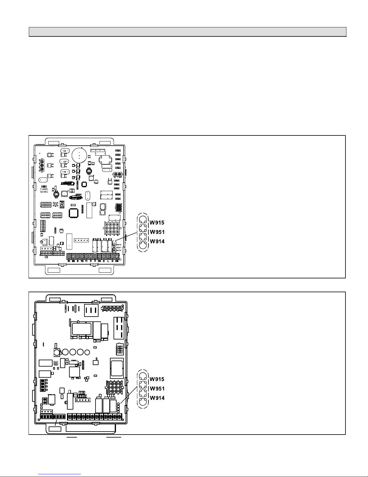
GAS FURNACE
VSM Furnace IFC Electrical Adjustments (G71MPP, SLP98, SL280V, EL296V)
NOTE − Follow all equipment installation instructions provided with each unit.
The variable-speed motor (VSM) in the furnace is controlled by the integrated furnace control (IFC). Adjustment of these
drive controls is made by cutting the clippable on-board links and selecting DIP switch settings. This is described in the
following paragraphs.
The G71MPP, SLP98, SL280V, and EL296V blower motor speed must be adjusted to produce the zoning CFM requirements managed by the zone control system.
The Harmony III zone control´s pulse width modulated (PWM) output signal is connected to the DS terminal on the furnace
control. The PWM signal, along with any other thermostat request (G, W1, or W1+W2), controls fan speed linearly between
the minimum and maximum CFM for the furnace as determined by the cool speed DIP switches (see G71MPP & SLP98
Installation Instructions for settings).
Locate the integrated control in the furnace control box area. Before connecting the zone control panel to the integrated
control, complete the applicable electrical adjustments shown in figures 18 or 19.
Electrical Adjustments
1. In all casescut the clippable on-board link W914 Dehum − Harmony
(between R & DS, see figure 18); if not cut, the zone control panel DS
fuse will blow.
2. DO NOT CUT the clippable on-board link W915 2 Stage Compr (between Y1 & Y2).
+
HUM
EAC
Do NOT cut any wires in the variable speed motor harness.
ON−BOARD LINKS:
W915 2 Stage Compr (Y1 to Y2)DO NOT CUT
W951 Heat Pump (R to O)DO NOT CUT
W914 Dehum − Harmony (R to DS)CUT IN ALL CASES
Figure 18. G71MPP & SLP98 Integrated Furnace Control (IFC) Electrical Adjustments
Electrical Adjustments
1. In all casescut the clippable on-board link W914 Dehum − Harmony
(between R & DS, see figure 18); if not cut, the zone control panel DS
fuse will blow.
2. DO NOT CUT the clippable on-board link W915 2 Stage Compr (between Y1 & Y2).
Do NOT cut any wires in the variable speed motor harness.
ON−BOARD LINKS:
W915 2 Stage Compr (Y1 to Y2)DO NOT CUT
W951 Heat Pump (R to O)DO NOT CUT
W914 Dehum − Harmony (R to DS)CUT IN ALL CASES
R
I + I −CRI + I −
C
W1W2GY2Y1CCRDHLODS
Figure 19. SL280V & EL296V Integrated Furnace Control (IFC) Electrical Adjustments
Page 25
HARMONY IIIT ZONE CONTROL SYSTEM
Page 26

GAS FURNACE
Set the upper limit of blower CFM as follows:
1. Determine the maximum system CFM requirements (sum of all the individual zones).
2. From the Blower Motor Performance tables (see G71MPP, SLP98, SL280V, EL296V Furnace Installation Instructions)
determine the HIGH speed cool DIP switch setting that corresponds to this CFM.
3. Set the HIGH speed cool DIP switch setting on the integrated control to this value.
NOTE − The lower limit of blower CFM is factory set. It is not field adjustable.
The minimum airflow achieved by the G71MPP, SLP98, SL280V, EL296V when connected to a Harmony IIIt zone control
is listed in the table 6 (see page 14).
A 3% duty cycle corres
ponds to the minimum CFM, and a 97% duty cycle corresponds to the maximum CFM.
NOTE − Any on/off delays present for a heating or cooling sequence are still present with Harmony IIIt zone control operation.
VSM Furnace System Operation (G71MPP, SLP98, SL280V, EL296V)
The dehumidification on−board clippable link W914 Dehum − Harmony (R to DS) on the G71MPP, SLP98, SL280V, and
EL29V integrated control must be cut for operation with the Harmony III zone control (see figure 18). Once the link is cut,
the presence of the Harmony III zone control system, versus a standard dehumidification control, is automatically detected by the integrated control.
IMPORTANT − DO NOT alter blower harness!
When the integrated control is properly connected to a Harmony IIIt zone control, operation is as follows:
S Integrated control DIP switches 1 and 2, which configure the control for operation with various types of thermostats,
are ignored.
S The zone control sends a W1 Signal to the furnace which goes through its normal ignition sequence as described in
the G71MPP, SLP98, SL280V, and EL29V installation instructions.
S The blower will start and operate at the minimum blower speed after a 45 second delay.
S After the temperature of the DAS rises above 100ºF the zone control will provide a PWM signal to the furnace on termi-
nal DS based upon the Zone PIAB Jumper selections (and the heating air reduction jumper).
S The blower speed (CFM) is set according to the pulse width modulated (PWM) signal from the Harmony IIIt zone con-
trol.
S The blower speed adjusts immediately with PWM adjustments.
S The furnace firing rate is based on current operating CFM and internal lookup table for midpoint temperature rise. If
resulting firing rate is below minimum firing rate, it will operate at minimum fire rate. Accordingly, if resulting firing rate
is above maximum firing rate, it will operate at maximum firing rate.
S Firing rate adjusts anytime the PWM deviates by more than 5% (e.g. 60% > 65%).
NOTE − Integrated control DIP switches 14 thru 19 are not disabled, and can be used in conjunction with Harmony III to
increase or decrease airflow volume during heating operation.
NOTE − DIP switches 14−19 adjust firing rate when Harmony is detected. Air volume is controlled by Harmony. The
furnace looks at air volume and determines proper firing rate based on DIP switch 14−19 settings. See G71MPP &
SLP98 Installation Instructions for adjustment options.
S Integrated Control W2 terminal to Harmony IIIt zone control:
Since the furnace automatically adjusts firing rate to match CFM to achieve a target temperature rise, connection of
Harmony IIIt zone control to W2 terminal on the integrated control is not required.
With W2 connected, lower firing rates can be used for W1 demand usually resulting in greater comfort levels per zone. If
temperature cannot be maintained, then W2 will quickly increase firing rates to satisfy demand.
If discharge air temperature is too low, the integrated control W2 can be connected to Harmony IIIt zone control to
cause the furnace to increase firing rate. Every two minutes, the integrated control looks at W2. If W2 is ON, the firing
rate increases by 5%. This 5% increase is added to the desired firing rate as determined by the PWM. Therefore, if a
50% duty cycle corresponds to a 70% firing rate, after 2 minutes of W2, that same 50% duty cycle will correspond to a
75% firing rate. This will last for the remainder of the heat cycle.
When W2 goes from ON to OFF, the integrated control decreases the firing rate by 5%.
505023M 08/11
Page 26
Page 27

GAS FURNACE
Harmony IIIt Installation Setup Worksheets
G71MPP, SLP98, SL280V, EL296VCooling/Heating; (Non−Heat Pump Applications)
Job Name: Indoor Unit Model: Outdoor Unit Model:
Indoor Unit setup:
- Cut on−board link W914 DEHUM OR HARMONY (R to DS) on furnace IFC control (if not cut, fuse will blow in Harmony III zone control board)
- W2 connection from Harmony III to SLP98 or G71MPP is optional – see Harmony III / furnace installation instructions for details
- DIP switch settings (ON or OFF):
1 OFF (DIP switch 1 – leave at factory setting – ignored by Harmony III)
2 OFF (DIP switch 2 – leave at factory setting – ignored by Harmony III)
3 OFF (DIP switch 3 – leave at factory setting – ignored by Harmony III)
4 ON (DIP switches 4 & 5 determine heating blower off" delay – recommended 180 seconds)
5 ON I
6 OFF (DIP switches 6 & 7 – leave at factory setting – ignored by Harmony III)
7 OFF I
8 (DIP switches 8 & 9 – cooling blower speed – determines maximum system cfm – see G71MPP blower tables)
9 I
10 (DIP switches 10 & 11–cooling blower adjust–determines maximum system cfm – see G71MPP blower tables)
11 I
12 OFF (DIP switches 12 & 13 – leave at factory setting – ignored by Harmony III)
13 OFF I
14 OFF (DIP switches 14,15,&16 – sets low fire, minimum capacity, firing rate − DEFAULT SETTING SHOWN & IS
15 OFF I
16 OFF I
17 OFF (DIP switches 17,18,&19 – sets high fire, 100% capacity, firing rate − DEFAULT SETTING SHOWN & IS
18 OFF I
19 OFF I
Harmony IIIt Panel setup:
- Heating staging jumper (circle one): 85 90 100 110 120 130 (Recommended 120 deg−F)
- Zone 1 PIAB 140F DAS jumper in place (circle one): Yes No (see Harmony III install instructions for info)
- Cooling staging jumper (circle one): 50 55 60 (select desired discharge air temp during cooling)
- Cont. Air Reduction jumper (circle one): 0 25 50 75 (% airflow reduction for continuous fan operation)
- Heating Air Reduction jumper (circle one): 0 20 40 (% air flow reduction for heating mode)
- System Configuration jumpers (circle one): HP GAS (Set to GAS)
- Stages (circle one): 2COOL 1COOL (Set to match condenser, 1 or 2 stage)
- Stages (circle one): 2HP 1HP (ignored for gas heat, non−heat pump application)
- E−HEAT Stages (circle one): DF 1 2 3 (ignored for gas heat, non−heat pump application)
- Desired total system cfm with all zones calling− _________ Total system cfm per tables− __________ Minimum cfm− ________
- Zone 1 – Name ___________________ Desired cfm ____________ PIAB Setting ____________% Actual cfm ____________
- Zone 2 – Name ___________________ Desired cfm ____________ PIAB Setting ____________% Actual cfm ____________
- Zone 3 – Name ___________________ Desired cfm ____________ PIAB Setting ____________% Actual cfm ____________
- Zone 4 – Name ___________________ Desired cfm ____________ PIAB Setting ____________% Actual cfm ____________
NOTEAll of the above are recommended starting" positions for the SLP98 or G71MPP DIP switches and Harmony III jumpers. Slight variations may
be required during system start up and operation checks.
RECOMMNEDED STARTING POINT– see Harmony III/furnace install instruction)
RECOMMNEDED STARTING POINT– see Harmony III/furnace install instruction)
Field Wiring Checklist:
- Indoor Unit Wiring Completed:
- DS" on Harmony III to DS" on indoor unit connected,
- "C" on indoor unit connected to Harmony III transformer C",
- No connection to Y1" or Y2" on indoor unit.
- Outdoor Unit Wiring Completed.
- Thermostat and Damper Wiring Completed.
- Discharge Sensor wired to Harmony III.
Page 27
HARMONY IIIT ZONE CONTROL SYSTEM
Page 28

GAS FURNACE
VSM Furnace IFC Electrical Adjustments (G61MPV & G60UHV)
NOTE − Follow all equipment installation instructions provided with each unit.
Variable-speed furnaces are equipped with an integrated furnace control (IFC). The blower motor speed must be adjusted,
by DIP switch setting selection, to produce the cfm required when all the zones are demanding heating or cooling which is
managed by the zone control system.
Locate the integrated control in the furnace control box area. Switch settings on the control affect blower CFM. Before connecting the zone control panel to the integrated control, complete the applicable electrical adjustments as shown in figure
20.
®
Electrical Adjustments
1. In all casescut the clippable on−board link W914 Dehum −
Harmony (between R & DS, shown left).
2. DO NOT CUT clippable on−board link W951 Heat Pump (be-
tween R & O).
3. DO NOT CUT clippable on−board link W915 2 Stage Compr
(between Y1 & Y2).
4. Be sure T’STAT jumper is on TWO".
5. In all casescut and tape wires 2 & 13 on the motor end of
the VSM harness connecting the integrated control to the motor (see figure 21).
ON−BOARD LINKS:
W951 HEAT PUMPDO NOT CUT
W914 DEHUM − HARMONYCUT IN ALL CASES
W915 2 STAGE COMPRDO NOT CUT
IMPORTANT
Be sure to cut jumper W914; if not cut,
the zone control panel DS fuse will blow.
Electrical Adjustments
1. In all casescut the clippable on−board link W914 Dehum −
Harmony (between R & DS, shown left).
2. DO NOT CUT clippable on−board link W951 Heat Pump (be-
tween R & O).
3. DO NOT CUT clippable on−board link W915 2 Stage Compr
(between Y1 & Y2).
4. Be sure to set "T’STAT Heat Stages" to "ON" (2−stage).
5. In all casescut and tape wires 2 & 13 on the motor end of
the VSM harness connecting the integrated control to the motor (see figure 21).
Figure 20. G61MPV & G60UHV Integrated Furnace Control Electrical Adjustments
505023M 08/11
ON−BOARD LINKS:
W915 2 STAGE COMPRDO NOT CUT
W951 HEAT PUMPDO NOT CUT
W914 DEHUM − HARMONYCUT IN ALL CASES
Page 28
Page 29

VSM Furnaces IFC Electrical Adjustments (G61MPV & G60UHV [cont’d])
J46 PLUG FROM THE MOTOR
GAS FURNACE
TO MOTOR J/P49
CUT AND TAPE
WIRE #13 (FURNACE
APPLICATION ONLY)
VIEW FROM WIRE ENTRY SIDE OF PLUG
VIEW LOOKING DIRECTLY INTO WIRE ENTRY SIDE OF PLUG
CUT & TAPE
WIRE #2
LOOK FOR RIDGE
TO IDENTIFY PIN 1
POSITION
1
9
VIEW FROM MATING SIDE OF PLUG
8
16
Figure 21. Integrated Control Cable Modifications for G61MPV/G60UHV Furnaces
Set the upper limit of blower CFM as follows:
1. Determine the maximum system CFM requirements (sum of all the individual zones).
2. From the Blower Motor Performance table (see unit installation instructions) determine the HIGH Speed cool DIP switch
setting that corresponds to this CFM.
3. Set the HIGH Speed cool DIP switch setting on the control to this value.
NOTE − The lower limit of blower CFM is factory set. It is not field adjustable. See table 6 on page 14 for minimum airflow
values for specific furnace models.
Page 29
HARMONY IIIT ZONE CONTROL SYSTEM
Page 30

GAS FURNACE
VSM Furnace System Operation (G61MPV & G60UHV)
This section describes the operation of the zone control in
a system that uses a gas furnace.
Zone Thermostats
Only electronic thermostats with a C" terminal may be
used with the zone control system. The zone control system distinguishes between heat pump and heat/cool applications via the SYSTEM jumper placement on the zone
control panel.
1. Cool / Heat / Auto−Changeover ModesZone thermostats send a heating or cooling signal to the zone control panel. Thermostat servicing zone 1 is the central
control thermostat. Zones 2, 3 and 4 each have their
own thermostat. Thermostats may be standard or autochangeover type.
Heat and cool demands present at the same time from
different zones (opposing demands) are satisfied on a
first come first served basis. If a heating demand and a
cooling demand reach the zone control panel at the
same time, the heating demand is satisfied first. If opposing demands persist, the system will work to satisfy the current demand for a maximum of 20 minutes,
then switch over and try to satisfy the opposing demand for a maximum of 20 minutes. When either demand is satisfied, the system works to satisfy the other
demand.
NOTE − Allowing opposing demands to persist may
consume excess energy. If this condition continues,
check the installation (i.e. zone arrangement, supply
registers, return registers, zone loads etc.) and make
adjustments as necessary. Table 9 shows the time delays that may be expected when opposing demands
are received from the zone thermostats.
The zone control system acknowledges a new or opposing demand as soon as it is received by illuminating
that zone’s thermostat input lights. If the first demand
is not satisfied by the time the delays elapse, the system switches over and begins satisfying the opposing
demand. During the switch-over, a delay may be imposed before the system begins satisfying the new demand.
2. Fan On / Auto ModeZone thermostats can send a
continuous fan signal to the zone control system. The
zone control system will signal the blower to supply air
to zones calling for continuous fan while no other conditioning calls exist. When the zone control system receives a conditioning call while satisfying a demand for
continuous fan, it signals the damper controlling the
continuous-fan zone to close. After the conditioning
demand is satisfied, the continuous-fan zone damper
is signaled to reopen.
Balance Point Setting
(Dual Fuel Systems) Balance Point Sensor (kit 56A87)
communicates with the zone control panel whether or not
to force the Gas Furnace to satisfy heating demands,
based on a comparison of the Balance Point setting with
the outdoor temperature. Terminals 2−3 close on temperature fall to lock out heat pump.
Zone Mode
The zone control mode (Vacation switch OFF) utilizes the
zone control system’s full potential. While in this mode, the
zone control system will respond to demands from any
zone, controlling dampers and regulating blower CFM to
maintain comfort. When the system is in zone mode, the
zone control system responds to demands from any zone
thermostat. (Switch settings are shown in figures 17
through 26.)
The only OPEN supply-air dampers are those zones from
which a demand was received; all other dampers are
CLOSED. The blower operates at a speed based on the
position of the Zone PIAB selection jumpers (and the heating air reduction jumper, if a call for heat is present).
NOTE − To ensure that the zone control performs optimally,
avoid mixing air between the zones.
Central (Vacation) Mode
When in central mode (Vacation switch ON), the system
responds only to heating or cooling demands from the central control (Zone 1) thermostat; all zones will receive conditioned air. All dampers remain open and the blower operates at full speed (minus the amount selected by the
heating air reduction jumper). (Switch settings are shown
in figures 17 through 26.)
In Fan−Auto mode, the blower will cycle on and off with
each demand. During gas or electric-strip heating, the
blower may continue after the end of a demand until the
heater is cooled sufficiently.
Cooling Operation
When the Harmony IIIt zone control system receives a
thermostat cooling call, the following events occur:
S The zone control checks to make sure it has been at
S When timed−off delay is satisfied, the zone control
S The zone control checks the discharge air sensor for
S If, at any time, the discharge air sensor measures a
least 5 minutes since the last cooling call ended to prevent starting against high head pressures.
starts the outdoor unit with 1st−stage compressor and
slowly increases the indoor blower speed to achieve
proper CFM. Four minutes must elapse at this state to
allow the system to reach steady−state operation before staging again.
proper temperature. If measured temperature is 7ºF or
more above the cooling staging jumper setting, then
Y2 energizes (if available). If both stages of cooling are
energized and 4 minutes has elapsed since the last
staging event, and the discharge air sensor (DAS) detects a temperature less than the cooling staging jumper, then Y2 is staged off.
temperature of 45ºF or below, the zone control de−energizes the Y1 and/or Y2 output, stopping the compressor and preventing the indoor coil from freezing
up. The compressor will not be energized again until
the temperature at the DAS rises by 10ºF and the
timed−off delay expires. During this time, continuous
fan is supplied to the zones calling for cooling.
505023M 08/11
Page 30
Page 31

VSM Furnace System Operation (G61MPV & G60UHV [cont’d})
Heating Operation
Gas furnaceIn this system, when the zone control re-
ceives a thermostat heating demand, the following events
occur:
S The zone control sends a W1 signal to the furnace, which
goes through its normal ignition sequence, except that while
the temperature at the DAS is below 100ºF, the zone control
instructs the blower to run at minimum speed.
S After the temperature at the DAS rises above 100ºF, the zone
control slowly increases the CFM delivered until it reaches
the correct setting. During a call for heat, the zone control
stages the furnace up and down to maintain the discharge air
temperature between the heating staging jumper setting and
20ºF above this jumper setting. There is a minimum 3 minute
delay between staging events.
NOTE − See page 26 for additional notes on operation with
G71MPP & SLP98 furnace.
Heat Pump with Electric HeatIn this system, when the
zone control receives a thermostat heating call, the following events occur:
S The zone control starts the heat pump on 1st−stage.
S If after 4 minutes, the temperature at the DAS is not within the
proper range (heating staging jumper setting and heating
staging jumper setting +20) the unit stages up or down, accordingly.
S If the air temperature cannot be maintained using the heat
pump alone, the zone control starts the electric heating
stages. Should the discharge temperature exceed 135ºF,
the compressor (and any electric heat that may be on) is
turned off and continuous fan runs (if the demand for heat remains) until the air temperature falls below 130ºF and the
minimum timed−off delay expires.
S If the heat pump goes into defrost mode, the zone control en-
ergizes all stages of compressor and the 1st−stage of electric
heat. If the defrost process lasts longer than 20 minutes, the
zone control, presuming a defrost board failure, de−energizes the heat pump and instructs electric heat to service the
remainder of the current heating call. (The heat pump will be
tried again on the next heating call.)
Dual Fuel−Heat Pump with Gas FurnaceIn this system, when it receives a thermostat heating call, the zone
control responds in one of two ways:
1. Outdoor temperature below balance point (balance point sensor closed, red Balance Point Sensor
LED on): the zone control sends a W1 signal to the fur-
nace to satisfy heat demands, staging the furnace to
maintain discharge air temperatures between 110ºF
and 130ºF.
2. Outdoor temperature above balance point (balance point sensor open, red Balance Point Sensor
LED off): the heat pump is first used to satisfy the demand. If, after 20 minutes, the heat pump fails to maintain the required discharge air temperature, the zone
control will discontinue using the heat pump and initiate furnace heating. (A five−minute delay exists between stopping the heat pump and starting the furnace.) In this mode, all heating calls for the next three
hours are serviced with the gas furnace. Also, diagnostic lights 2, 3, and 4 blink to indicate that the zone
control is operating within this 3−hour furnace lock−in
time. During this time, the zone control stages the furnace to maintain discharge air temperatures between
110ºF and 130ºF. After the 3−hour delay expires, the
heat pump will again be tried on the next heating call.
Defrost Tempering (Optional)
frost Operation on Page 23 for Defrost Tempering operation.
Emergency heat mode
When the unit is setup for heat pump and the emergency
heat switch is turned on, the unit will satisfy all heating demands with electric backup heat or, in a dual fuel system,
the heat demand is satisfied by the gas furnace.
Humiditrol® mode (Enhanced Dehumidification
Accessory)
When the unit is equipped for dehumidification (Enhanced
Dehumidification Accessory and Humiditrol® Zoning Accessory installed), the unit will satisfy all demands for dehumidification. Refer to supplemental kit information Dehumidification Interface Kit for Harmony IIIt Zone Control.
GAS FURNACE
If installed, refer to De-
Page 31
HARMONY IIIT ZONE CONTROL SYSTEM
Page 32

GAS FURNACE
Harmony IIIt Installation Setup Worksheets
G61MPV/G60UHVCooling/Heating; with Honeywell 2−stage IFC control (non−Heat Pump
applications)
Job Name: Indoor Unit Model: Outdoor Unit Model:
Indoor Unit setup:
- Cut on−board link W914 DEHUM OR HARMONY (R to DS) on furnace IFC control (if not cut, fuse will blow in zone control board)
- Cut and tape wires from pin # 2 and pin #13 on plug J46 of the VSM wiring harness routed from the motor to the Furnace Integrated control.
- Furnace IFC Control DIP switch settings (ON or OFF):
1 OFF (DIP switch 1 must be set to Off for 2−stage heating operation)
2 OFF (DIP switch 2 determines 2nd stage heat time delay & is ignored by Harmony III)
3 ON (DIP switches 3 & 4 determines heating blower off delay, recommended is 180 sec)
4 ON I
5 DIP switches 5 & 6 determines 2nd stage cooling blower speed or maximum system air vol.)
6 I
7 (DIP switches 7 & 8 determine blower adjust" setting for maximum system air volume)
8 I
9 OFF (DIP switches 9 & 10 determines cooling blower ramping profile & is ignored by Harmony III)
10 OFF I
11 OFF (DIP switches 11&12 determines heating blower speed & is ignored by Harmony III)
12 ON I
Harmony IIIt Panel setup:
- Heating staging jumper (circle one): 85 90 100 110 120 130 (Recommended 120 deg−F)
- Zone 1 PIAB 140F DAS jumper in place (circle one): Yes No (see install instructions for info)
- Cooling staging jumper (circle one): 50 55 60 (select desired discharge air temp during cooling)
- Cont. Air Reduction jumper (circle one): 0 25 50 75 (% airflow reduction for continuous fan operation)
- Heating Air Reduction jumper (circle one): 0 20 40 (% air flow reduction for heating mode)
- System Configuration jumpers (circle one): HP GAS (Set to GAS)
- Stages (circle one): 2COOL 1COOL (Set to match condenser, 1 or 2 stage)
- Stages (circle one): 2HP 1HP (ignored for gas heat, non−heat pump application)
- E−HEAT Stages (circle one): DF 1 2 3 (ignored for gas heat, non−heat pump application)
- Desired total system cfm with all zones calling− _________ Total system cfm per tables− _________ Minimum cfm− _________
- Zone 1 – Name:____________ Desired cfm:____________ PIAB Setting: ____________% Actual cfm: ____________
- Zone 2 – Name:____________ Desired cfm:____________ PIAB Setting: ____________% Actual cfm: ____________
- Zone 3 – Name:____________ Desired cfm:____________ PIAB Setting: ____________% Actual cfm: ____________
- Zone 4 – Name:____________ Desired cfm:____________ PIAB Setting: ____________% Actual cfm: ____________
NOTEAll of the above are recommended starting positions for DIP switches and Harmony III jumpers. Slight variations may be required during system start up and operation checks.
Field Wiring Checklist:
- Indoor Unit Wiring Completed:
- DS" on Harmony III to DS" on indoor unit connected,
- "C" on indoor unit connected to Harmony III transformer C",
- No connection to Y1" or Y2" on indoor unit.
- Outdoor Unit Wiring Completed.
- Thermostat and Damper Wiring Completed.
- Discharge Sensor wired to Harmony III.
505023M 08/11
Page 32
Page 33

GAS FURNACE
Furnace System Start−Up & Checkout
IMPORTANT
The zone control system power−up must occur at the same
time or before the furnace or air handler unit is powered up.
Powering the System (All Systems)
1. Adjust all thermostat settings so that no demand will occur.
2. Apply power to the zone panel transformer and to the furnace and observe the following: all four diagnostic LEDs will
light; then each individual diagnostic LED will light in sequence; then all four diagnostic LEDs will light and extinguish.
3. Finally, the status light will begin to flash, indicating proper operation. Perform the gas heating checks on pages 33
through 34.
Gas Heating Checkout (Single Zone)
Prerequisites:
S Zone 1 thermostat set to Heat
DAMPER 2,3,4 ON
DAMPER 1 OFF
FAN ON
(W) RED ON
W1 ON
HEATING ON
OUTPUT STATUS LEDs
1. Set zone 1 thermostat for a heat demand; check:
D Zone 1 thermostat W LED on (heating demand).
D Damper 1 LED off (damper open).
D Damper 2, 3, and 4 LEDs on (dampers closed).
D Output Heat W1 LED on (furnace on).
D Heating LED on.
The furnace begins ignition sequence after zone 1 has
demanded heat. The zone control system will start the
furnace blower on low speed (0 PIAB) 45 seconds after the combustion cycle has begun.
2. When 100ºF warm air is sensed by the discharge air
sensor, the fan LED will light and the blower will slowly
increase to speed required by the zone calling. The
blower operates at speed setting of PIAB jumper for
zone 1 and the jumper for heating air reduction. It may
require 60 − 90 seconds to reach this speed.
3. Set zone 1 thermostat for NO heat demand; check:
D Zone 1 thermostat W LED off (no heat demand).
D Output Heat W1 LED off.
D Fan LED off.
D Heating LED off.
D Damper LEDs 2−4 remain on until after 3-1/2 min-
ute purge; then off.
To check the amount of air being delivered to each
zone and to confirm that each individual zone damper
functions properly, repeat these steps for zones 2 − 4.
Page 33
HARMONY IIIT ZONE CONTROL SYSTEM
Page 34

GAS FURNACE
Gas Heating Checkout (Multiple Zone)
Prerequisites:
All zone thermostats set to Heat
S
(W) RED ON
W1 ON
DAMPER 2,3,4 OFF
FAN ON
Gas Heating Checkout (Central Control)
HEATING ON
OUTPUT STATUS LEDs
1. Set all zone thermostats for a heat demand; check for
the following:
D All zone thermostat W LEDs on (heat demands).
D LEDs dampers 1 − 4 off (all dampers open).
D Output Heat W1 LED on (furnace on).
D Heating LED on.
The furnace begins ignition sequence after a heat demand is detected. The zone control system will start
the furnace blower on low speed (0 PIAB) 45 seconds
after the combustion cycle has begun.
2. When 100ºF warm air is sensed by the discharge air
sensor, the fan LED comes on and the blower will
slowly increase to speed required by the zones calling.
The blower operates at a speed equivalent to the sum
of all zone PIAB jumpers but at a maximum not to exceed the setting of the heating air reduction jumper. It
may take the blower 60 to 90 seconds to reach this
speed.
3. Set all zone thermostats for NO heat demands; check:
D Output Heat W1 LED off.
D Heating LED off.
D Fan LED off (blower turns off after delay).
D All zone thermostat W LEDs off.
D DamperLEDs − Last zone thermostat demand re-
moved: LED is off (this zone’s damper remains
open during 3−1/2 minutepurge); other zones
damper LEDs are on during the 3−1/2 minute
purge (dampers closed). After 3−1/2 minute delay,
all dampers LEDs go off (dampers open).
Prerequisites:
Central mode switch on
S
S Red LED on the central mode fan switch on
(W) RED ON
CENTRAL
DAMPER 2,3,4 OFF
MODE ON
FAN ON
HEATING ON
OUTPUT STATUS LEDs
W1 ON
1. Set zone 1 thermostat for a heat demand; check:
D Zone 1 thermostat W LED on (heating demand).
D Output Heat W1 LED on (furnace on).
D Heating LED on.
D All damper LEDs off (damper open).
2. The furnace will begin its ignition sequence after Zone
1 has demanded heat. The zone control system will
start the furnace blower on low speed (0 PIAB air) 45
seconds after the combustion cycle has begun.
3. When 100ºF warm air is sensed by the discharge air
sensor, the fan LED will light and the blower will slowly
increase to speed. The blower will operate at a speed
equivalent to the PIAB calculated for all zones calling,
taking into account the heating air reduction jumper
position. It may take the blower 60 to 90 seconds to
reach this speed.
4. Remove the heat demand from zone 1 (no heat input
or output and no blower demand). Upon removal of the
demand from zone 1, check:
D Zone 1 thermostat W LED off (no heat demand).
D Output Heat W1 LED off.
D Fan LED off.
D Heating LED off.
After 3−1/2 minute purge time, furnace blower turns off.
505023M 08/11
Page 34
Page 35

Troubleshooting DiagramZone system with Gas Furnace
GAS FURNACE
- Are thermostats wired correctly?
- Does zone control system respond appropriately to demand?
- Heat/cool thermostat used? (Must not use heat pump thermostat.)
- Does electronic thermostat have relay switching output? If not, isolation relays may need to be used.
- 24VAC supplied to each thermostat terminal R from zone control system?
- Check each thermostat for output signal when calling. Heating output? Cooling output?
THERMOSTATS
- (No pressure Switch should be installed.)
- Do dampers respond to demand? 0
volts AC = open. 24 volts AC =
closed. Dampers should drive closed
when 24 volts is jumpered to damper
motor.
- Is wiring correct & in good condition?
DAMPERS
- Is discharge
probe installed?
- Is probe located
in discharge air
plenum as described on
Page 6?
- Is it wired cor-
rectly?
DISCHARGE
AIR SENSOR
HUMIDITROL ZONING
ACCESSORY CONTROL
- Have heating and cooling
staging jumpers been set for
desired 2nd stage operation?
- Are continuous & heating air re-
duction jumpers set correctly?
- Do jumpers provide appropriate
speed reduction? If no, check
indoor unit before replacing
zone control panel.
Heating/cooling
staging jumper
settings − page 10.
Air reduction
jumper
settings −
page 9.
PIAB jumper settings − page 8.
140F DAS
jumper
pages 8
& 10.
System Configuration & E−Heat
jumper settings − page 11.
- Line Voltage to transformer?
- 24VAC from transformer to zone control panel?
- Are all wire connections good? Are all wire connections correct?
Thermostat 2 Thermostat 1
W C Y G R
W C Y G R
ZONE PANEL TRANSFORMER
24
VAC
VARIABLE SPEED
FURNACE
POWER SUPPLY
120
VAC
- C" connected
to C"?
- Fuses OK?
2-STAGE
CONDENSING
UNIT
Y1
Y2
C
R
R
G
W1
W2
C
DS
Y1
Y2
TO FURNACE
- Are PIAB jumpers set correctly?
- Only 1 jumper per Zone? (Zone Control
System Jumper Settings (Page 8)
(NOTE: Zone 1 may have a second
jumper on 140F DAS pins)
- Has 140F DAS jumper been installed (if
required; see Page 8 & 10)?
- Are jumpers set cor-
rectly for furnace and
cooling? (Page 11)
Figure 22. Option 1 − Lennox Variable-Speed Gas Furnace and Lennox Condensing Unit
- Error code present? If
so, see troubleshooting/
diagnostic section of this
manual (Page 56).
Page 35
- Does outdoor unit respond to
demand?
- Is it operating properly?
- Are appropriate outputs ener-
gized in response to demand?
- Does zone control system en-
ergize appropriate outputs?
During Cooling? During Heating?
- 24VAC from furnace transform-
er to R?
- Does furnace respond to out-
puts?
- Does blower speed change as
zone demand changes? If no,
does DS output vary from 0 to
25VDC?
HARMONY IIIT ZONE CONTROL SYSTEM
- Verify Furnace jump-
ers/links cut or removed (see Pages 28 −
25) Page 39)
- Verify NO connections
made to Y1 or Y2.
Page 36
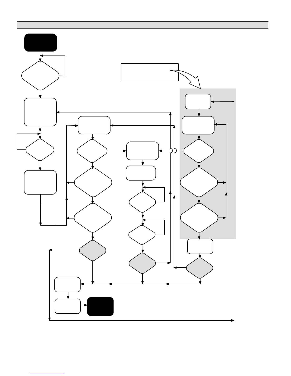
GAS FURNACE
TroubleshootingGas Heating Operation
HEATING
DEMAND
RECEIVED
3−Minutes
since completion
of last heating
demand
Energize W1 @
furnace; Ramp
indoor blower to
minimum CFM
setting
Discharge
air above
No
100°F
Ye s
Ramp indoor
blower to
heating staging
jumper setting
REFER TO DISCHARGE AIR
UPPER LIMIT DIAGRAM
(Page 37) FOR UPPER LIMIT
No
?
Ye s
Monitor
discharge air
temperature
Is
discharge
air at upper
?
No
No
No
De−energize
W1 @ furnace
limit
?
Discharge
air below heating
staging jumper
setting
Ye s
3−Minutes
minimum run time
in 1st stage
completed
?
Ye s
Heating
demand
satisfied
?
Ye s
Ye s
No
?
AND DIFFERENTIAL DETAILS.
Shut down all
heat stages
Continuous air
delivered to
calling zones
5 min
delay
complete
?
Discharge
air falls to
130°F
?
Heating
demand
satisfied
?
No
Ye s
No
Ye s
No
Ye s
Energize W2
@ furnace
Monitor
discharge air
temperature
Is
discharge
air at upper
Ye s
limit
?
No
Does
discharge air
temp. meet
heating staging
differential
3−Minutes
minimum run time
in 2nd stage
completed
De−energize
Heating
demand
No
satisfied
Ye s
No
?
Ye s
No
?
Ye s
W2
?
Hold dampers
open for 3½
minutes
505023M 08/11
BLOWER
SHUTDOWN
Page 36
Page 37
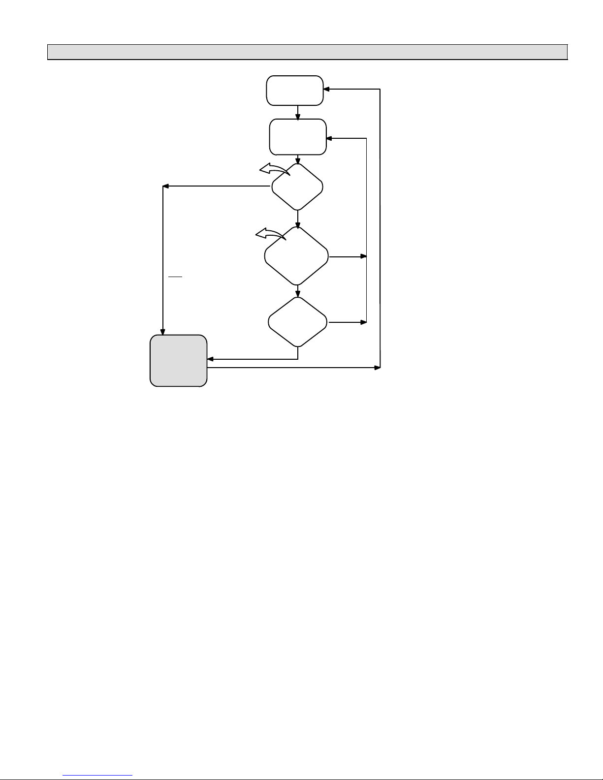
TroubleshootingDischarge Air Upper Limit & Differential Temperatures
Furnace
energized
Monitor
discharge air
temperature
Discharge air upper limit is
160ºF unless 140F DAS
jumper installed
Ye s
Differential is 20ºF above
heating staging jumper
setting with the following
exception:
Differential is 15ºF if the
140F DAS jumper is in
place on PIAB 1 terminals
and heating staging jumper is on 120 or 130.
Is
discharge
air at upper
limit
?
No
Does
discharge air
temp. meet
heating staging
differential
?
Ye s
No
GAS FURNACE
To / from the
appropriate
gas heating or
dual fuel
diagram
3−minute
minimum run-
time com-
pleted
?
Ye s
No
Page 37
HARMONY IIIT ZONE CONTROL SYSTEM
Page 38
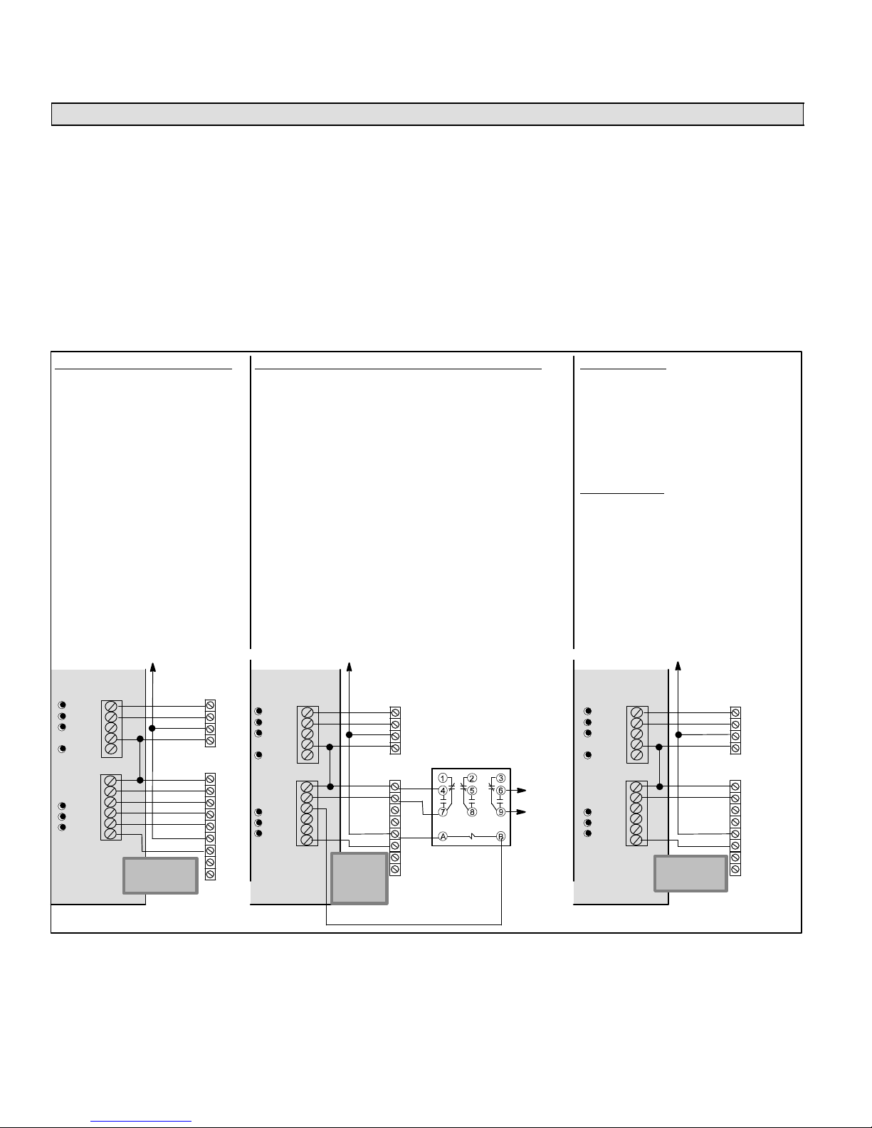
AIR HANDLERS
AIR HANDLERS
Variations on Common Condensing Unit Applications
Heating/Cooling Equipment Installation
Follow all equipment installation instructions provided with
each unit.
Air Handler Wiring
After the air handler unit is installed, field wire the line voltage as shown in the installation instructions provided with
the unit. Use thermostat wire to connect the air handler to
the zone control panel (see figure 15) and to connect wire
from zone control panel 24V C" to air handler terminal strip
C".
COOLING WITH ELECTRIC HEAT
S System configuration jumpers:
HP;
1COOL or 2COOL.
S E−Heat stage jumper set on #
agreeing with # of available heat
stages.
S E−HEAT Selector Switch always
ON.
S As applicable, cut jumpers and
harness wires (see Blower Control
Adjustments − Air Handlers on
Page 39).
HOT WATER COIL (CBWMV, CBX32MV or CBX40UHV)
S System configuration jumpers:
GAS;
1COOL or 2COOL;
Others do not matter.
S AHC (prior to revision 06): Cut or remove 24 volt jumper Y1
to DS.
S AHC (revision 06): Cut R to DS clippable link on air handler
control.
S CBWMV has no K20 relay, therefore wiring harness modifi-
cation (shown in figure 25, Page 39) is not required.
− Cut or remove 24v jumper Jumper Y1 to DS
− Remove Pink wire from TB1−W1 to J46−2 on CBWMV
NOTE − K212 field hookup relay must be field provided on the
CBX32MV or CBX40.
NOTE − DAS must be located downstream of the cooling coil and
HW coil
NOTE − Be sure to remove the factory installed jumper bar
between W1 to W2 and W2 to W3 (CBX40 or CBX32MV
rev 06) or remove the jumper wires between R to W1 and R
to W2 (CBX32MV prior to rev 06).
Variations
Several variations may be required for specific applications. Figure 23 shows alternate wiring and describes specific jumper configurations and other special modifications
required for each variation. Aside from the variations described in figure 23, the connectivity is the same as shown
in figure 17 (Page 24).
COOLING ONLY
S System configuration jumpers:
GAS;
1COOL or 2COOL;
Others do not matter.
S As applicable, cut jumpers and harness
wires (see Blower Control Adjustments
− Air Handlers on Page 39).
HEATING ONLY
NOTE − JUMPER between RC and RH
must be in place on the control!
For any option or variation, connect thermostat wire between C" on terminal strip(s) of controlled equipment and zone control panel 24VAC C" terminal.
Y1
Y2
O
RC
W1−Def
RH
G
W1
W2
W3
DS
Equipment
Equipment
IMPORTANT!
DO NOT MAKE
CONNECTIONS
TO Y1 AND Y2
Condensing
Unit
Y1
Y2
C
R
R
G
W1
W2
W3
C
DS
Y1
Y2
VSM Air
Handler
with Elec-
tric Heat
Y1
Y2
O
RC
W1−Def
RH
G
W1
W2
W3
DS
Equipment
Equipment
Condensing
IMPOR-
TANT! DO
NOT MAKE
CONNECTIONS TO
Y1 AND Y2
Unit
VSM
Handler
CBWMV AND
CBX32MV OR
Y1
CBX40UHV USED
Y2
C
WITH HOT WATER
R
COIL
R
G
W1
W2
C
DS
K212 FIELD
Y1
HOOKUP
Y2
RELAY MUST
BE PROVIDED
ON CBX32MV
Air
OR CBX40
TO
BOILER
OR
ZONE
CONTROL
Y1
Y2
O
RC
W1−Def
RH
G
W1
W2
W3
DS
Equipment
Equipment
Condensing
IMPORTANT!
DO NOT MAKE
CONNECTIONS
TO Y1 AND Y2
Unit
VSM Air
Handler
Y1
Y2
C
R
R
G
W1
W2
C
DS
Y1
Y2
Figure 23. Harmony IIIt Zone Control System − Variations on Common Applications
505023M 08/11
Page 38
Page 39

AIR HANDLERS
Air Handler Control Electrical Adjustments (All model VSM Air Handlers)
Electrical AdjustmentsCommunicating CBX32MV (revision 06) and CBX40UHV (all)
Electrical Adjustments
As shown in this diagram, make
the following adjustments:
1. Cut on board link R to DS
(Dehum or Harmony).
2. Remove Jumper Bars from
W1 to W2 and W2 to W3.
3. DO NOT CUT on board links
Y1−Y2 2 STAGE COMPR
and R−O HEAT PUMP
Y1−Y2 2 Stage Compr
and R−0 Heat Pump
CUT on board
Link R−DS
DO NOT CUT
on board links
Remove
W1−W2 and W2−W3
Jumper Bars from the
terminal strip
Figure 24. Electrical Adjustments for Air Handler Control CBX32MV (revision 06) & CBX40UHV (all)
Electrical AdjustmentsNon−communicating CBX32MV (prior to revision 06), CB31MV and CBWMV
These air handler blower motors are controlled by the BDC3 drive control; CFM adjustment Is by jumper setting selection.
Locate the BDC3 board in the blower control box. Before connecting the zone control panel to the BDC3 board, complete all
of the applicable electrical adjustments as shown in figure 25.
NOTE − Before cutting wires or jumpers, be sure your installation is not affected by Variations on Common Condensing Unit Applications" figure 23 (Page 38).
Electrical Adjustments
As shown in this diagram, make the following adjustments:
In all cases except Cooling Only" or CBWMV units:
1. CUT wire near the BDC3 board JP1 pin 2
2. tape exposed end of short JP1 pin 2 wire
3. re−route wire connected to K20 terminal 4; strip end and
connect to terminal G" (K20 wiring change not required
on CBWMV)
If CBWMV, remove pink wire TB1−W1 to J46−2
Except for Cooling Only" units, remove any jumper(s) between R − W2 or R − W3
DO NOT CUT jumper R − O
JP1
BDC3
K20 INDOOR
BLOWER RELAY
4
1
7
6
3
9
Figure 25. Electrical Adjustments for Air Handler Control CBX32MV (pre−rev. 06), CB31MV & CBWMV
Set the upper limit of blower CFM as follows:
1. Determine the maximum system CFM requirements (sum of all the individual zones).
2. From the Blower Motor Performance table in the unit’s installation instructions, determine the COOL Speed jumper
setting that corresponds to this CFM; then set the COOL Speed jumper setting on the BDC3 board to this value.
For more information on setting blower speed, refer to section on Blower Speed and Adjustment" in the blower unit’s installation instructions.
DO NOT CUT Jumper Y1 − Y2
In all cases, CUT Jumper DS − Y1
Page 39
HARMONY IIIT ZONE CONTROL SYSTEM
Page 40

AIR HANDLERS
Harmony IIIt Installation Setup Worksheets
CBX32MV/CBX40UHVCooling/Heating; Electric Strip Heat (non−Heat Pump applications)
Job Name: Indoor Unit Model: Outdoor Unit Model:
CBX40UHV and CBX32MV Revision 06 Indoor Unit setup:
- Cut on−board link R to DS DEHUM or HARMONY"
- Remove any factory−installed jumpers bars from W1 to W2 or W2 to W3.
- Air Handler Control jumper settings:
COOL: This setting, along w/ ADJUST setting, determines maximum system CFM (See blower tables)
ADJUST: Setting affects both heating and cooling blower speeds (see blower tables to determine setting)
HEAT: HIGH Heating blower speed selectioin – Ignored by Harmony III
DELAY: 4 Cooling blower ramping – Ignored by Harmony III
BLOWER ONLY CFM: Continuous fan speed – Ignored by Harmony III
EVENHEAT: EVENHEAT is not used with Harmony III
CBX32MV prior to Revision 06 Indoor Unit setup:
- Remove DS to Y1 jumper
- The wire from K20 terminal 4 to BDC3 board JP1 pin 2 must be re−routed to establish an electrical connection between K20 terminal 4 and terminal G. Cut
the wire near JP1 pin 2. Using the wire still connected to K20 terminal 4, strip the cut end and connect it to terminal G. Tape the exposed end of the short
JP1pin 2 wire (See Harmony III Installation Instructions for more details).
- Remove any factory−installed jumpers between terminal R and W1, W2, or W3.
- BDC3 control clip jumper settings:
COOL: This setting, along w/ ADJUST setting, determines maximum system CFM (See blower tables)
ADJUST: Setting affects both heating and cooling blower speeds (see blower tables to determine setting)
HEAT: 4 Heating blower speed selectioin – Ignored by Harmony III
DELAY: 4 Cooling blower ramping – Ignored by Harmony III
Harmony IIIt Panel setup:
- Heating staging jumper (circle one): 85 90 100 110 120 130 (Recommended 120 deg−F)
- Zone 1 PIAB 140F DAS jumper in place (circle one): Yes No
- Cooling staging jumper (circle one): 50 55 60 (select desired discharge air temp during cooling to stage compressor)
- Cont. Air Reduction jumper (circle one): 0 25 50 75 (% airflow reduction for continuous fan operation)
- Heating Air Reduction jumper (circle one): 0 20 40 (% air flow reduction for heating mode)
- System Configuration jumpers (circle one): HP GAS (Set to HP)
- Stages (circle one): 2COOL 1COOL (Set to match condenser, 1 or 2 stage)
- Stages (circle one): 2HP 1HP (Ignored for non−heat pump – w/ strip heat applications – setting does not matter)
- E−HEAT Stages (circle one): DF 1 2 3 (Set to # of strip ht stages (<8KW=1)(>8KW & <30KW=2)( 30KW=3)
- Emergency Heat switch on Harmony III zone panel must be set to ON.
- Desired total system cfm with all zones calling− ___________ cfm, Actual total system cfm− ___________
- CB unit minimum" cfm ____________ (determined by unit spec as listed below unit blower table)
- Zone 1 – Desired cfm ____________ PIAB Setting ____________% Actual cfm ____________
- Zone 2 – Desired cfm ____________ PIAB Setting ____________% Actual cfm ____________
- Zone 3 – Desired cfm ____________ PIAB Setting ____________% Actual cfm ____________
- Zone 4 – Desired cfm ____________ PIAB Setting ____________% Actual cfm ____________
NOTEAll of the above are recommended starting positions for DIP switches and Harmony III jumpers. Slight variations may be required during system start up and operation checks.
Field Wiring Checklist:
- Indoor Unit Wiring Completed:
- DS" on Harmony III to DS" on indoor unit connected,
- "C" on indoor unit connected to Harmony III transformer C",
- No connection to Y1" or Y2" on indoor unit.
- Outdoor Unit Wiring Completed.
- Thermostat and Damper Wiring Completed.
- Discharge Sensor wired to Harmony III.
505023M 08/11
Page 40
Page 41

AIR HANDLERS
Harmony IIIt Installation Setup Worksheets (continued)
CBX32MV/CBX40UHVHeat Pump; Electric Strip Heat
Job Name: Indoor Unit Model: Outdoor Unit Model:
CBX40UHV and CBX32MV Revision 06 Indoor Unit setup:
- Cut on−board link R to DS DEHUM or HARMONY"
- Remove any factory−installed jumpers bars from W1 to W2 or W2 to W3.
- Air Handler Control jumper settings:
COOL: This setting, along w/ ADJUST setting, determines maximum system CFM (See blower tables)
ADJUST: Setting affects both heating and cooling blower speeds (see blower tables to determine setting)
HEAT: HIGH Heating blower speed selectioin – Ignored by Harmony III
DELAY: 4 Cooling blower ramping – Ignored by Harmony III
BLOWER ONLY CFM: Continuous fan speed – Ignored by Harmony III
EVENHEAT: EVENHEAT is not used with Harmony III
CBX32MV prior to Revision 06 Indoor Unit setup:
- Remove DS to Y1 jumper
- The wire from K20 terminal 4 to BDC3 board JP1 pin 2 must be re−routed to establish an electrical connection between K20 terminal 4 and terminal G. Cut
the wire near JP1 pin 2. Using the wire still connected to K20 terminal 4, strip the cut end and connect it to terminal G. Tape the exposed end of the short
JP1pin 2 wire (See Harmony III Installation Instructions for more details).
- Remove any factory−installed jumpers between terminal R and W1, W2, or W3.
- BDC3 control clip jumper settings:
COOL: This setting, along w/ ADJUST setting, determines maximum system CFM (See blower tables)
ADJUST: Setting affects both heating and cooling blower speeds (see blower tables to determine setting)
HEAT: 4 Heating blower speed selectioin – Ignored by Harmony III
DELAY: 4 Cooling blower ramping – Ignored by Harmony III
Harmony IIIt Panel setup:
- Heating staging jumper (circle one): 85 90 100 110 120 130 (Recommended 90 deg−F)
- Zone 1 PIAB 140F DAS jumper in place (circle one): Yes No
- Cooling staging jumper (circle one): 50 55 60 (select desired discharge air temp during cooling to stage compressor)
- Cont. Air Reduction jumper (circle one): 0 25 50 75 (% airflow reduction for continuous fan operation)
- Heating Air Reduction jumper (circle one): 0 20 40 (Must be set to 0% on heat pump systems)
- System Configuration jumpers (circle one): HP GAS (Set to HP)
- Stages (circle one): 2COOL 1COOL (Set to match condenser, 1 or 2 stage)
- Stages (circle one): 2HP 1HP (Set to heat pump stages, 1 or 2 stage)
- E−HEAT Stages (circle one): DF 1 2 3 (Set to # of strip ht stages (<8KW=1)(>8KW & <30KW=2)( 30KW=3)
- Desired total system cfm with all zones calling− ___________ cfm, Actual total system cfm− ___________
- CB unit minimum" cfm ____________ (determined by unit spec as listed below unit blower table)
- Zone 1 – Desired cfm ____________ PIAB Setting ____________% Actual cfm ____________
- Zone 2 – Desired cfm ____________ PIAB Setting ____________% Actual cfm ____________
- Zone 3 – Desired cfm ____________ PIAB Setting ____________% Actual cfm ____________
- Zone 4 – Desired cfm ____________ PIAB Setting ____________% Actual cfm ____________
NOTEAll of the above are recommended starting positions for DIP switches and Harmony III jumpers. Slight variations may be required during system start up and operation checks.
Field Wiring Checklist:
- Indoor Unit Wiring Completed:
- DS" on Harmony III to DS" on indoor unit connected,
- "C" on indoor unit connected to Harmony III transformer C",
- No connection to Y1" or Y2" on indoor unit.
- Outdoor Unit Wiring Completed.
- Thermostat and Damper Wiring Completed.
- Discharge Sensor wired to Harmony III.
- Heat Pump Pressure Switch wired to Harmony III.
Page 41
HARMONY IIIT ZONE CONTROL SYSTEM
Page 42

AIR HANDLERS
Harmony IIIt Installation Setup Worksheets (continued)
CBX32MV/CBX40UHV – Cooling Only or Cooling with Hot Water Coil (non−Heat Pump)
Job Name: Indoor Unit Model: Outdoor Unit Model:
CBX40UHV and CBX32MV Revision 06 Indoor Unit setup:
- Cut on−board link R to DS DEHUM or HARMONY"
- For Hot Water Coil OnlyAdd K212 Relay & wire per Harmony III wiring detail.
NOTE − Discharge air sensor must be located down stream of cooling coil and hot water coil.
- Air Handler Control jumper settings:
COOL: This setting, along w/ ADJUST setting, determines maximum system CFM (See blower tables)
ADJUST: Setting affects both heating and cooling blower speeds (see blower tables to determine setting)
HEAT: HIGH Heating blower speed selectioin – Ignored by Harmony III
DELAY: 4 Cooling blower ramping – Ignored by Harmony III
BLOWER ONLY CFM: Continuous fan speed – Ignored by Harmony III
EVENHEAT: EVENHEAT is not used with Harmony III
CBX32MV prior to Revision 06 Indoor Unit setup:
- Remove DS to Y1 jumper
- For Hot Water Coil OnlyAdd K212 Relay & wire per Harmony III wiring detail.
NOTE − Discharge air sensor must be located down stream of cooling coil and hot water coil.
- BDC3 control clip jumper settings:
COOL: This setting, along w/ ADJUST setting, determines maximum system CFM (See blower tables)
ADJUST: Setting affects both heating and cooling blower speeds (see blower tables to determine setting)
HEAT: 4 Heating blower speed selectioin – Ignored by Harmony III
DELAY: 4 Cooling blower ramping – Ignored by Harmony III
Harmony IIIt Panel setup:
- Heating staging jumper (circle one): 85 90 100 110 120 130 (Cooling only – setting does not matter; Hot water − set at 120)
- Zone 1 PIAB 140F DAS jumper in place (circle one): Yes No (Cooling only – setting does not matter)
- Cooling staging jumper (circle one): 50 55 60 (select desired discharge air temp during cooling–50 deg−F suggested)
- Cont. Air Reduction jumper (circle one): 0 25 50 75 (% airflow reduction for continuous fan operation)
- Heating Air Reduction jumper (circle one): 0 20 40 ( Cooling only – setting does not matter; Hot Water set at % reduction for Heating mode)
- System Configuration jumpers (circle one): HP GAS (Set to GAS)
- Stages (circle one): 2COOL 1COOL (Set to match condenser, 1 or 2 stage)
- Stages (circle one): 2HP 1HP (ignored; non−heat pump application – setting does not matter)
- E−HEAT Stages (circle one): DF 1 2 3 (non−heat pump – setting does not matter )
- Desired total system cfm with all zones calling ___________ cfm, Actual total system cfm− ___________
- CB unit minimum" cfm ____________ (determined by unit spec listed below unit blower table)
- Zone 1 – Desired cfm ____________ PIAB Setting ____________% Actual cfm ____________
- Zone 2 – Desired cfm ____________ PIAB Setting ____________% Actual cfm ____________
- Zone 3 – Desired cfm ____________ PIAB Setting ____________% Actual cfm ____________
- Zone 4 – Desired cfm ____________ PIAB Setting ____________% Actual cfm ____________
NOTEAll of the above are recommended starting positions for DIP switches and Harmony III jumpers. Slight variations may be required during system start up and operation checks.
Field Wiring Checklist:
- Indoor Unit Wiring Completed:
- DS" on Harmony III to DS" on indoor unit connected,
- "C" on indoor unit connected to Harmony III transformer C",
- No connection to Y1" or Y2" on indoor unit.
- Outdoor Unit Wiring Completed.
- Thermostat and Damper Wiring Completed.
- Discharge Sensor wired to Harmony III and if a hot water coil is used, the sensor must be located down stream of the hot water coil.
505023M 08/11
Page 42
Page 43

DUAL FUEL
Zone control system wiringDual Fuel Application
DUAL FUEL
Heating/Cooling Equipment Installation
Follow all equipment installation instructions provided with
each unit.
PRESSURE SWITCH
21J18 (HFC−22)
27W13 (HFC−410A)
DAMPERS
(Spring open, power close)
DISCHARGE AIR SENSOR 88K38 (included)
Connections for REMOTE
VACATION SWITCH OR
Humiditrol® Zoning Accessory
Vacation OFF for individual
Vacation ON for all zones to be
conditioned at the same time.
Emergency Heat OFF to allow
Heat Pump to provide heat.
Emergency Heat ON to force
auxiliary (backup) heat to pro-
vide all heating (disallows heat
pump from providing any heat).
NOTE: SELECT #
OF HP STAGES
BY PLACING
JUMPER IN
APPROPRIATE
POSITION. (2−STG
HP SHOWN)
zone control.
See System Configuration & E−Heat jumper settings − page 11.
BALANCE POINT
SENSOR Kit 56A87
1 2 3
Heat/cool staging
jumper settings −
page 10.
Air reduction
jumper
settings −
page 9.
PIAB jumper settings − page 8.
Heat Pump Unit Wiring
After the heat pump unit is installed, field wire the line voltage as shown in the installation instructions provided with
the unit. Use thermostat wire to connect the heat pump to
the zone control panel (see figure 26).
CONNECT TO THE
SAME POWER
SUPPLY AS THE
Thermostat 2 Thermostat 1
W C Y G R W C Y G R
GAS FURNACE
24
VAC
ZONE CONTROL
TRANSFORMER
120
VAC
IMPORTANT
Connect
thermostat-gauge
wire to integrated
control C" terminal
NOTE − Do not wire Y" wire(s) from the
Harmony IIIt zone control panel to the
furnace terminal strip. Doing so causes
140F DAS
jumper
pages 8
& 10.
ON G71MPP & SLP98
Furnace − W2 Not
required, but may
be connected to
increase firing rate.
IMPORTANT! Connectivity is NOT COMPLETE until all
electrical adjustments (jumpers and wiring changes) have
been made. See Integrated Control Electrical Adjustments (beginning on Page 28).
the motor to search" for proper CFM.
HEAT PUMP
R
C
Y1
Y2
O
W1
R
G
W1
W2
C
IMPORTANT!
DO NOT MAKE
CONNECTIONS
TO Y1 AND Y2
DS
Y1
Y2
VARIABLE
SPEED
FURNACE
[67M41], for defrost tempering kit)
SEE IMPORTANT NOTE BELOW!
DT2 (S89) Limit Control (Optional
Figure 26. Harmony IIIt Zone Control System Option 3 −
Lennox Heat Pump & Lennox Variable-Speed Gas Furnace (Dual Fuel)
Page 43
HARMONY IIIT ZONE CONTROL SYSTEM
Page 44

DUAL FUEL
Dual Fuel System Start−Up & Checkout
IMPORTANT
The zone control system power−up must occur at the same
time or before the furnace or air handler unit is powered up.
Powering the System (All Systems)
1. Adjust all thermostat settings so that no demand will occur.
2. Apply power to the zone panel transformer and to the furnace and observe the following: all four diagnostic LEDs will
light; then each individual diagnostic LED will light in sequence; then all four diagnostic LEDs will light and extinguish.
3. Finally, the status light will begin to flash, indicating proper operation. Perform the dual fuel gas heating checks on pages
44 through 46.
Dual Fuel Gas Heating Checkout (Single Zone)
Prerequisites:
Zone 1 thermostat set to Heat.
S
S Balance Point Sensor set at higher temperature than outdoor
BPS-sensed temperature (red balance point sensor LED
on).
OR
S Balance Point Sensor inputs jumpered to simulate cold out-
door temperature below balance point (red balance point
sensor LED on).
1. Set zone 1 thermostat for a heat demand; check:
D Zone 1 thermostat W LED on (heating demand).
D Damper 1 LED off (damper open).
D Damper 2, 3, and 4 LEDs on (dampers closed).
D Output Heat W1 LED on (furnace on).
D Heating LED on.
The furnace begins ignition sequence after zone 1 has
demanded heat. The zone control system will start the
furnace blower on low speed (0 PIAB) 45 seconds after the combustion cycle has begun.
DAMPER 2,3,4 ON
DAMPER 1 OFF
FAN ON
(W) RED ON
W1 ON
HEATING ON
OUTPUT STATUS LEDs
2. When 100ºF warm air is sensed by the discharge air
sensor, the fan LED will light and the blower will slowly
increase to speed required by the zone calling. The
blower operates at speed setting of PIAB jumper for
zone 1 and the jumper for heating air reduction. It may
require 60 − 90 seconds to reach this speed.
3. Set zone 1 thermostat for NO heat demand; check:
D Zone 1 thermostat W LED off (no heat demand).
D Output Heat W1 LED off.
D Fan LED off.
D Heating LED off.
D Damper LEDs 2−4 remain on until after 3-1/2 min-
ute purge; then off.
To check the amount of air being delivered to each
zone and to confirm that each individual zone damper
functions properly, repeat these steps for zones 2 − 4.
505023M 08/11
Page 44
Page 45
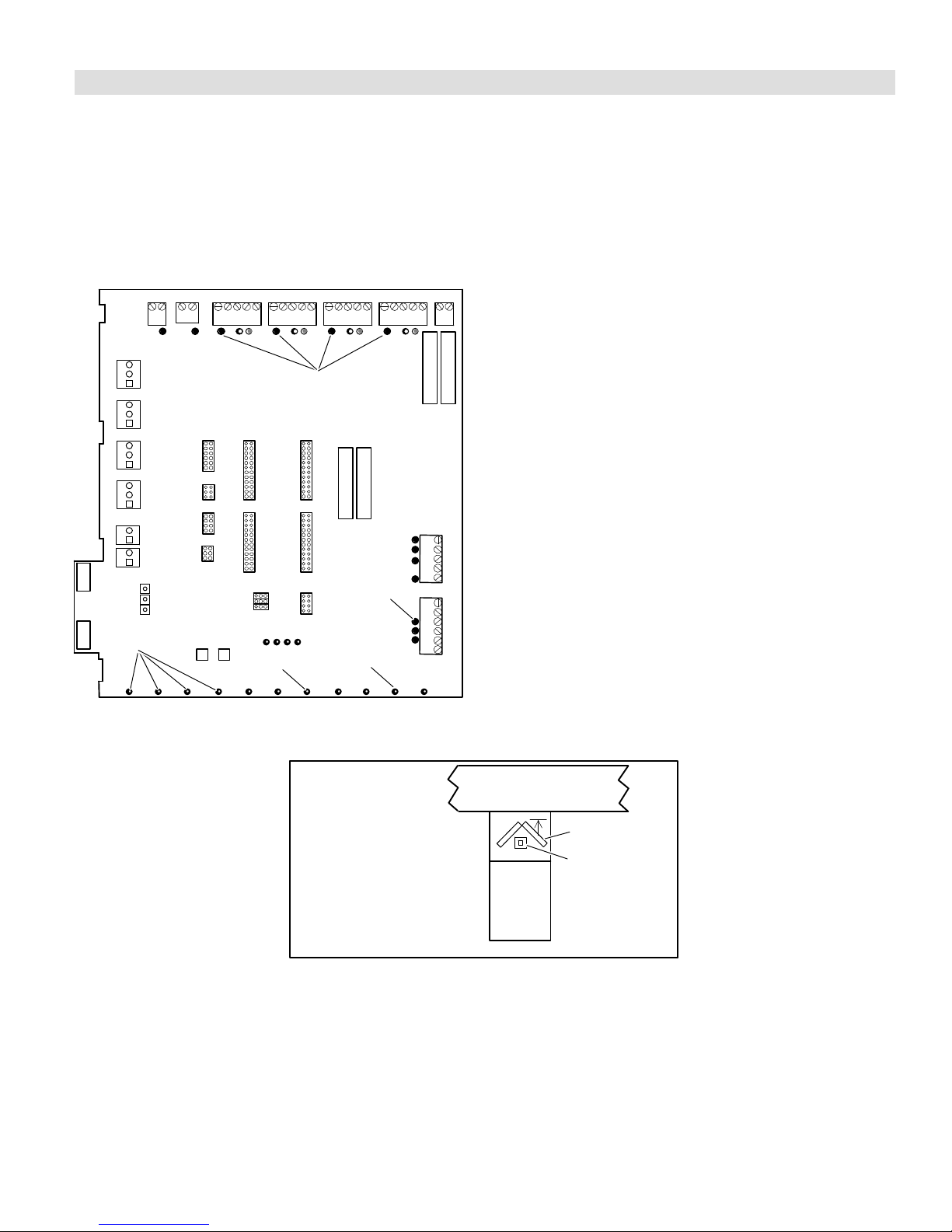
Dual Fuel Gas Heating Checkout (Multiple Zone)
Prerequisites:
All zone thermostats set to Heat.
S
S Balance Point Sensor set at higher temperature than outdoor
BPS-sensed temperature (red balance point sensor LED
on).
OR
S Balance Point Sensor inputs jumpered to simulate cold out-
door temperature below balance point (red balance point
sensor LED on).
(W) RED ON
DUAL FUEL
1. Set all zone thermostats for a heat demand; check for
the following:
D All zone thermostat W LEDs on (heat demands).
D LEDs dampers 1 − 4 off (all dampers open).
D Output Heat W1 LED on (furnace on).
D Heating LED on.
The furnace begins ignition sequence after a heat demand is detected. The zone control system will start
the furnace blower on low speed (0 PIAB) 45 seconds
after the combustion cycle has begun.
2. When 100ºF warm air is sensed by the discharge air
sensor, the fan LED comes on and the blower will
slowly increase to speed required by the zones calling.
The blower operates at a speed equivalent to the sum
of all zone PIAB jumpers but at a maximum not to exceed the setting of the heating air reduction jumper. It
may take the blower 60 to 90 seconds to reach this
speed.
DAMPER 2,3,4 OFF
FAN ON
Defrost Tempering (Kit 67M41)
Install the defrost tempering sensor (if used)
where shown. (See
504,797M installation instructions.)
W1 ON
HEATING ON
OUTPUT STATUS LEDs
Typical Upflow
Furnace Shown
3. Set all zone thermostats for NO heat demands; check:
D Output Heat W1 LED off.
D Heating LED off.
D Fan LED off (blower turns off after delay).
D All zone thermostat W LEDs off.
D DamperLEDs − Last zone thermostat demand re-
moved: LED is off (this zone’s damper remains
open during 3−1/2 minutepurge); other zones
damper LEDs are on during the 3−1/2 minute
purge (dampers closed). After 3−1/2 minute delay,
all dampers LEDs go off (dampers open).
plenum
coil
furnace
front
defrost tempering
sensor/limit control (if used in
Option 3)
Figure 27. Defrost Tempering Sensor Placement
Page 45
HARMONY IIIT ZONE CONTROL SYSTEM
Page 46
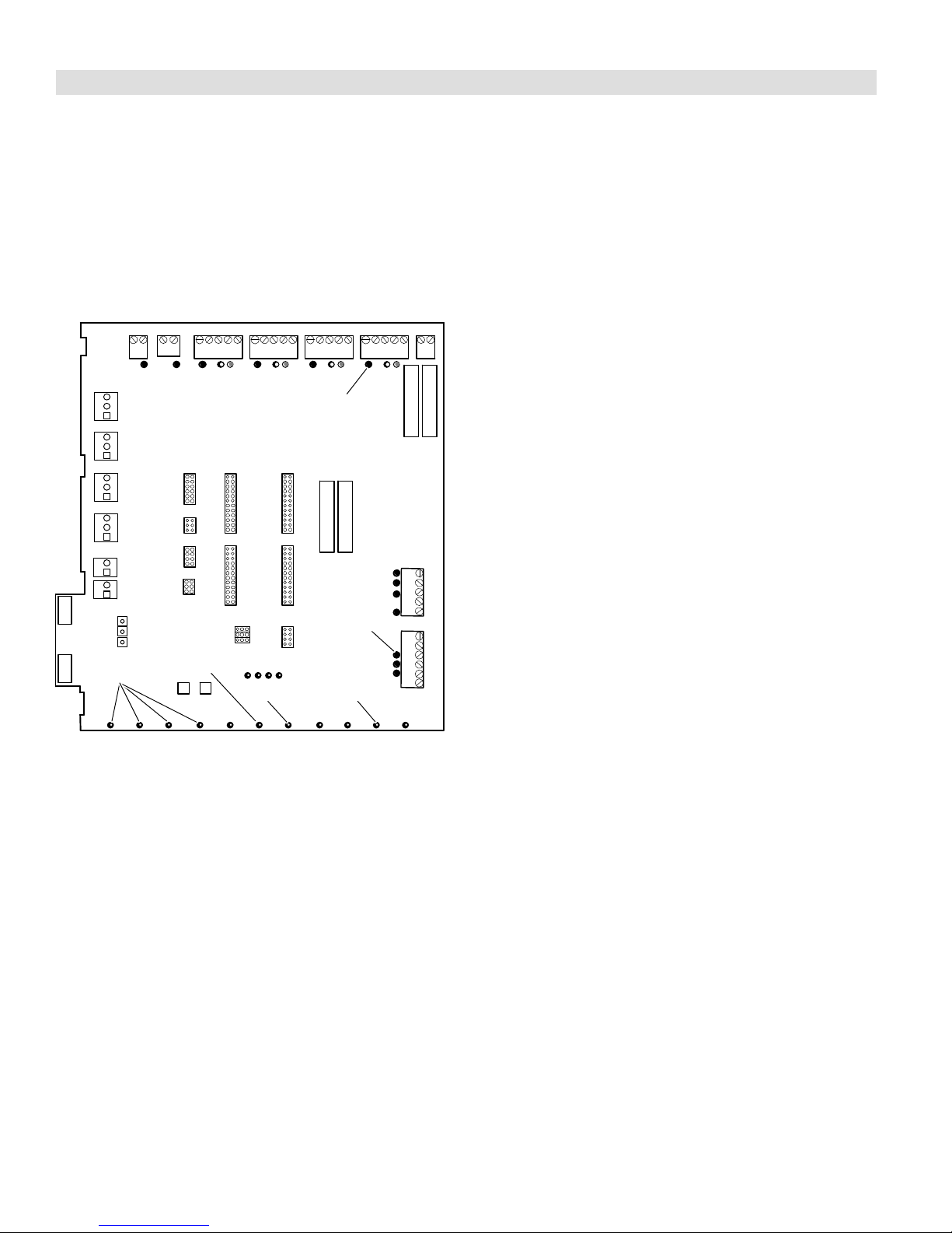
DUAL FUEL
Dual Fuel Gas Heating Checkout (Central Control)
Prerequisites:
Central mode switch on.
S
S Red LED on the central mode fan switch on.
S Zone 1 thermostat set to Heat.
S Balance Point Sensor set at higher temperature than outdoor
BPS-sensed temperature (red balance point sensor LED
on).
OR
S Balance Point Sensor inputs jumpered to simulate cold out-
door temperature below balance point (red balance point
sensor LED on).
1. Set zone 1 thermostat for a heat demand; check:
D Zone 1 thermostat W LED on (heating demand).
D Output Heat W1 LED on (furnace on).
D Heating LED on.
D All damper LEDs off (damper open).
2. The furnace will begin its ignition sequence after Zone
1 has demanded heat. The zone control system will
start the furnace blower on low speed (0 PIAB air) 45
seconds after the combustion cycle has begun.
DAMPER 2,3,4 OFF
CENTRAL
MODE ON
(W) RED ON
W1 ON
HEATING ONFAN ON
OUTPUT STATUS LEDs
3. When 100ºF warm air is sensed by the discharge air
sensor, the fan LED will light and the blower will slowly
increase to speed. The blower will operate at a speed
equivalent to the PIAB calculated for all zones calling,
taking into account the heating air reduction jumper
position. It may take the blower 60 to 90 seconds to
reach this speed.
4. Remove the heat demand from zone 1 (no heat input
or output and no blower demand). Upon removal of the
demand from zone 1, check:
D Zone 1 thermostat W LED off (no heat demand).
D Output Heat W1 LED off.
D Fan LED off.
D Heating LED off.
After 3−1/2 minute purge time, furnace blower turns off.
505023M 08/11
Page 46
Page 47
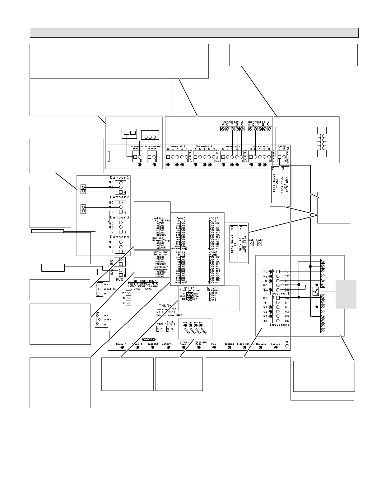
TroubleshootingZoning system with Dual Fuel
DUAL FUEL
- Are thermostats wired correctly?
- Does zone control system respond appropriately to demand?
- Does electronic thermostat have relay switching output? If relay with SCR output is used, not, isola-
tion relays may need to be used.
- 24VAC supplied to each thermostat terminal R from zone control system?
- Check each thermostat for output signal when calling. Heating output W1? Cooling output Y1?
- Pressure Switch installed. in correct position?
- Does switch open when high pressure condition is simulated (temporarily
blocking airflow in heating mode)?
- Does zone control system respond appropriately when high pressure condi-
tion is simulated (temporarily disconnecting switch simulates high pressure).
- Balance Point Sensor Installed and correctly wired?
- Contacts close on temperature fall?
THERMOSTATS
- Do dampers respond to demand? 0
volts AC = open. 24 volts AC =
closed. Dampers should drive closed
when 24 volts is jumpered to damper
motor.
PRESSURE
SWITCH
BALANCE
POINT
SENSOR
1 2 3
- Is wiring correct & in good condition?
DAMPERS
- Is discharge
probe installed?
- Is probe located
in discharge air
plenum as described on
Page 6?
- Is it wired cor-
rectly?
DISCHARGE
AIR SENSOR
HUMIDITROL ZONING
ACCESSORY CONTROL
- Have heating and cooling
staging jumpers been set
for desired 2nd stage operation?
- Are continuous & heating air
reduction jumpers set correctly? On heat pumps, Heating
Air Reduction must be 0%.
- Do jumpers provide appropri-
ate speed reduction? If no,
check indoor unit before replacing zone control panel.
Heating/cooling
staging jumper
settings − page 10.
Heating
Cooling
Air
reduction
jumper
settings −
page 9.
PIAB jumper settings − page 8.
140F DAS
jumper pgs
8 & 10.
System Configuration & E−Heat
jumper settings − page 11.
- Line Voltage to transformer?
- 24VAC from transformer to zone control panel?
- Are all wire connections good? Are all wire connections correct?
ZONE PANEL TRANSFORMER
POWER SUPPLY
TO FURNACE
24
VAC
120
VAC
- C" connected
to C"?
- Fuses OK?
HEAT PUMP
R
C
Y1
Y2
DT2 (S89)
O
Limit Con-
W1
trol (Optional, for
R
defrost
tempering
G
kit)
W1
W2
C
DS
Y1
Y2
VARIABLE
SPEED
FURNACE
- Are PIAB jumpers set cor-
rectly?
- Only 1 jumper per Zone?
(Zone Control System Jumper Settings (Page 8) (NOTE:
Zone 1 may have a second
jumper on 140F DAS pins)
- Has 140F DAS jumper been
installed (if required; see
Page 8 & 10)?
- Are jumpers set correct-
ly for heating and cooling? (Page 11)
Figure 28. Option 3 − Lennox Heat Pump & Lennox Variable-Speed Gas Furnace (Dual Fuel)
- Error code present?
If so, see troubleshooting/diagnostic
section of this
manual (Page 56).
Page 47
- Does outdoor unit respond to demand?
- Is it operating properly?
- Test Defrost. Does outdoor unit initiate and
terminate defrost correctly?
- Check defrost tempering switch, if installed.
- Does zone control system respond
appropriately during defrost?
- Are appropriate outputs energized in
response to demand?
- Does zone control system energize appropriate outputs? During Cooling? During
Heating? During Defrost? During Emer. Heating?
- Verify Furnace jumpers/
links cut or removed
(see Pages 28 − 25)
- Verify NO connections
made to Y1 or Y2.
- 24VAC from furnace transformer to R?
- Does indoor unit respond to outputs? Cooling? Heating? Defrost? Emer. Heating?
- Does blower speed change as zone demand changes? If no, does DS output vary
from 0 to 25VDC?
HARMONY IIIT ZONE CONTROL SYSTEM
Page 48

DUAL FUEL
TroubleshootingDual Fuel Operation (Below Balance Point)
HEATING
DEMAND
RECEIVED
temp. Below
Balance Point
Sensor setpoint
3−Minutes
since completion
of last heating
No
Ye s
Energize W1
@ furnace; Ramp
indoor blower to
minimum CFM
air (DAS) above
No
Ye s
Ramp indoor
heating staging
jumper setting
BLOWER
SHUTDOWN
Hold dampers
open for 3½
Ambient
?
Ye s
demand
?
setting
Discharge
100°F
?
blower to
minutes
See Above Balance
setpoint flow diagram
No
No
minimum run time
No
De−energize
W1 @ furnace
Point Sensor
(Page 50).
Monitor dis-
charge air
temperature
Is
discharge
air at upper
limit
?
No
Discharge
air below heating
staging jumper
setting
?
Ye s
3−Minutes
in 1st stage
completed
?
Ye s
Heating
demand
satisfied
?
Ye s
REFER TO DISCHARGE AIR
UPPER LIMIT DIAGRAM
(Page 49) FOR UPPER LIMIT
AND DIFFERENTIAL DETAILS.
De−energize
Ye s
No
W1 & W2
@ furnace
Continuous air
delivered to
calling zones
5 min
delay
complete
?
Ye s
Discharge
air falls to
130°F
?
Ye s
Heating
demand
satisfied
?
Ye s
No
No
No
Energize W2
@ furnace
Monitor dis-
charge air
temperature
discharge
air at upper
Ye s
No
limit
No
Does
discharge air
temp. meet
heating staging
differential
3−Minutes
minimum run time
in 2nd stage
completed
De−energize
Heating
demand
satisfied
Ye s
Is
?
No
?
Ye s
No
?
Ye s
W2
?
505023M 08/11
Page 48
Page 49

TroubleshootingDischarge Air Upper Limit & Differential Temperatures
Furnace
energized
Monitor
discharge air
temperature
Discharge air upper limit is
160ºF unless 140F DAS
jumper installed
Ye s
Differential is 20ºF above
heating staging jumper
setting with the following
exception:
Differential is 15ºF if the
140F DAS jumper is in
place on PIAB 1 terminals
and heating staging jumper is on 120 or 130.
Is
discharge
air at upper
limit
?
No
Does
discharge air
temp. meet
heating staging
differential
?
Ye s
No
DUAL FUEL
To / from the
appropriate
gas heating or
dual fuel
diagram
3−minute
minimum run-
time com-
pleted
?
Ye s
No
Page 49
HARMONY IIIT ZONE CONTROL SYSTEM
Page 50

DUAL FUEL
TroubleshootingDual Fuel Operation (Above Balance Point
HEATING
DEMAND
RECEIVED
5−min
lapse since-
completion of last
No
Energize 1st &/or 2nd stage
compressor(s) & Ramp in-
door blower to cooling stag-
heating
demand
?
Ye s
ing jumper setting
Ambient
temp. Above
Balance Point
sensor setpoint
?
Ye s
Heat pump
locked out
(see NOTE)
?
No
See Below Balance Point
sensor setpoint flow diagram
(Page 48)
Ye sNo
REFER TO DISCHARGE AIR
UPPER LIMIT DIAGRAM
(Page 49) FOR UPPER LIMIT
AND DIFFERENTIAL DETAILS.
NOTE − On energize W1 furnace,
compressor heat is locked out − all
heat calls for the next three hours
use gas heat only
Energize W1
@ furnace
(see NOTE)
Monitor
discharge air
temperature
Discharge
air DAS above
135°F
Discharge
air below heating
staging jumper
No
No
setting
Ye s
20−minute
minimum runtime
completed
Ye s
Heating
demand
satisfied
De−energize all com-
pressor stages; start
5−minute delay
Monitor
discharge air
temperature
Continuous air
delivered to
calling zones
Shutdown all
Ye s
?
No
?
?
Ye s
?
No
compressor
stages
5 min
delay
complete
?
Ye s
Discharge
air falls to
130°F
?
Ye s
Heating
demand
satisfied
?
No
System
in 3−hr backup
heat mode
?
No
Ye s
No
No
Ye s
Shutdown all
heating stages
BLOWER
SHUTDOWN
De−energize
all heat pump
and furnace
stages
5 min delay
complete
?
Ye s
Ye s No
No
Ye s
Is
discharge
air at upper
limit
?
No
Does
discharge air
temp. meet
heating staging
differential
?
Ye s
3−minute
minimum runtime
completed
?
Ye s
Heating
demand
satisfied
?
No
No
505023M 08/11
Page 50
Page 51
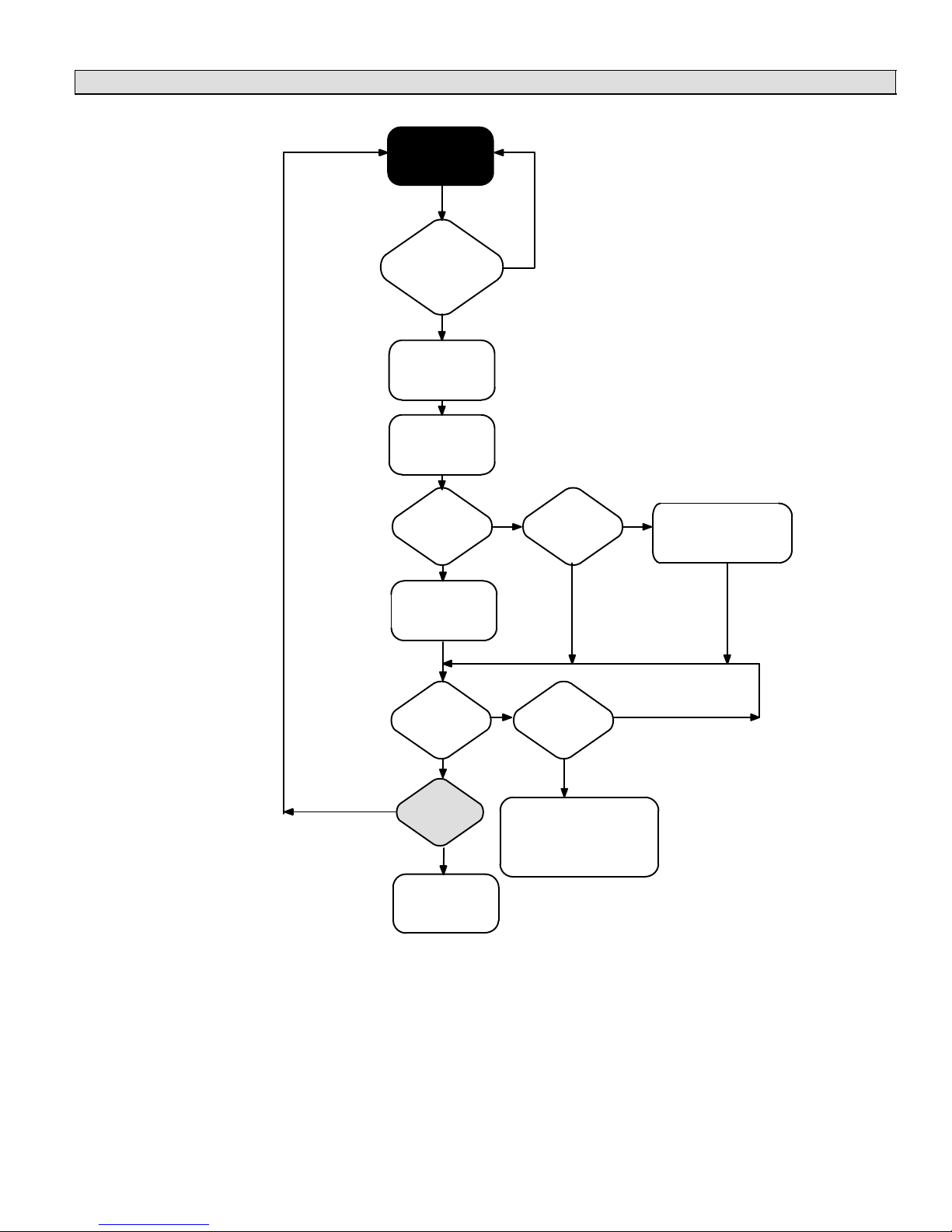
TroubleshootingDefrost Operation
NORMAL
HEAT PUMP
OPERATION
Defrost
control detects
need for defrost
cycle
?
Ye s
Heat Pump
enters defrost
Harmony III
control energizes
all compressor
stages
DUAL FUEL
No
Dual Fuel
Harmony III
sends signal to
W1 at indoor unit
Defrost
completed
Heating
demand
No
satisfied
Ye s
De−energize
all compressor
stages
Defrost
?
?
?
Ye s
No
No
Ye s
Tempering
?
No
Defrost
period exceeds
20 minutes
?
Ye s
Harmony III control
de−energizes all
compressor stages − uses
auxiliary heat to complete
existing heat demand
HP cycles W1 OFF at
90ºF and ON at 80ºF
Ye s
during defrost cycle.
No
Page 51
HARMONY IIIT ZONE CONTROL SYSTEM
Page 52

DUAL FUEL
Harmony IIIt Installation Setup Worksheets
G61MPV/G60UHVDual Fuel; with Honeywell 2−stage IFC control (Heat Pump applications)
Job Name: Indoor Unit Model: Outdoor Unit Model:
Miscellaneous Items:
- Install Pressure Switch in the outdoor unit per Harmony III installation instructions (27W13 for R410A or 21J18 for R22)
- Install Balance Point Sensor (56A87) as per installation instructions. Set to desired outdoor lock out temperature for HP
- Install Optional Defrost Tempering Sensor 67M41 (if used) per installation instructions. NOTE: MUST be located in coil delta plate between furnace and
coil
- Install Discharge Air Sensor per installation instructions. The location of the sensor is CRITICAL for proper system operation
Indoor Unit setup:
- Cut on−board link W914 DEHUM OR HARMONY (R to DS) on furnace IFC control (if not cut, fuse will blow in zone control board)
- Cut and tape wires from pin # 2 and pin #13 on plug J46 of the VSM wiring harness routed from the motor to the Furnace Integrated control.
- Furnace IFC Control DIP switch settings (ON or OFF):
1 OFF (DIP switch 1 must be set to Off for 2−stage heating operation)
2 OFF (DIP switch 2 determines 2nd stage heat time delay & is ignored by Harmony III)
3 ON (DIP switches 3 & 4 determines heating blower off delay, recommended is 180 sec)
4 ON I
5 DIP switches 5 & 6 determines 2nd stage cooling blower speed or maximum system air vol.)
6 I
7 (DIP switches 7 & 8 determine blower adjust" setting for maximum system air volume)
8 I
9 OFF (DIP switches 9 & 10 determines cooling blower ramping profile & is ignored by Harmony III)
10 OFF I
11 OFF (DIP switches 11&12 determines heating blower speed & is ignored by Harmony III)
12 ON I
Harmony IIIt Panel setup:
- Heating staging jumper (circle one): 85 90 100 110 120 130 (Recommended 90 deg−F)
- Zone 1 PIAB 140F DAS jumper in place (circle one): Yes No (see install instructions for info)
- Cooling staging jumper (circle one): 50 55 60 (select desired discharge air temp during cooling)
- Cont. Air Reduction jumper (circle one): 0 25 50 75 (% airflow reduction for continuous fan operation)
- Heating Air Reduction jumper (circle one): 0 20 40 (must be set to 0% for heat pump systems)
- System Configuration jumpers (circle one): HP GAS (Set to HP)
- Stages (circle one): 2COOL 1COOL (Set to match condenser, 1 or 2 stage)
- Stages (circle one): 2HP 1HP (Set to match heat pump stages, 1 or 2 stage)
- E−HEAT Stages (circle one): DF 1 2 3 (Must be set to DF for dual fuel application)
- Desired total system cfm with all zones calling− _________ Total system cfm per tables− _________ Minimum cfm− _________
- Zone 1 – Name:____________ Desired cfm:____________ PIAB Setting: ____________% Actual cfm: ____________
- Zone 2 – Name:____________ Desired cfm:____________ PIAB Setting: ____________% Actual cfm: ____________
- Zone 3 – Name:____________ Desired cfm:____________ PIAB Setting: ____________% Actual cfm: ____________
- Zone 4 – Name:____________ Desired cfm:____________ PIAB Setting: ____________% Actual cfm: ____________
NOTEAll of the above are recommended starting positions for DIP switches and Harmony III jumpers. Slight variations may be required during system start up and operation checks.
Field Wiring Checklist:
- Indoor Unit Wiring Completed:
- DS" on Harmony III to DS" on indoor unit connected,
- "C" on indoor unit connected to Harmony III transformer C",
- No connection to Y1" or Y2" on indoor unit.
- Outdoor Unit Wiring Completed.
- Thermostat and Damper Wiring Completed.
- Discharge Sensor wired to Harmony III.
- Heat Pump Pressure Switch wired to Harmony III.
505023M 08/11
Page 52
Page 53

DUAL FUEL
Harmony IIIt Installation Setup Worksheets (continued)
G71MPP, SLP98, SL280V, EL296VDual Fuel (Heat Pump Applications)
Job Name: Indoor Unit Model: Outdoor Unit Model:
Miscellaneous Items:
- Install Pressure Switch in the outdoor unit per Harmony III installation instructions (27W13 for R410A or 21J18 for R22)
- Install Balance Point Sensor (56A87) as per installation instructions. Set to desired outdoor lock out temperature for HP
- Install Optional Defrost Tempering Sensor 67M41 (if used) per installation instructions. NOTE: MUST be located in coil delta plate between furnace and
coil
- Install Discharge Air Sensor per installation instructions. The location of the sensor is CRITICAL for proper system operation
Indoor Unit setup:
- Cut on−board link W914 DEHUM OR HARMONY (R to DS) on furnace IFC control (if not cut, fuse will blow in Harmony III zone control board)
- W2 connection from Harmony III to SLP98 or G71MPP is optional – see Harmony III / furnace installation instructions for details
- DIP switch settings (ON or OFF):
1 OFF (DIP switch 1 – leave at factory setting – ignored by Harmony III)
2 OFF (DIP switch 2 – leave at factory setting – ignored by Harmony III)
3 OFF (DIP switch 3 – leave at factory setting – ignored by Harmony III)
4 ON (DIP switches 4 & 5 determine heating blower off" delay – recommended 180 seconds)
5 ON I
6 OFF (DIP switches 6 & 7 – continuous indoor blower speed – ignored by Harmony III)
7 OFF I
8 (DIP switches 8 & 9 – cooling blower speed – determines maximum system cfm – see furnace blower tables)
9 I
10 (DIP switches 10 & 11–cooling blower adjust–determines maximum system cfm – see furnace blower tables)
11 I
12 OFF (DIP switches 12 & 13 – cooling mode blower ramping – ignored by Harmony III)
13 OFF I
14 OFF (DIP switches 14,15,&16 – sets low fire, minimum capacity, firing rate − DEFAULT SETTING SHOWN & IS
15 OFF I
16 OFF I
17 OFF (DIP switches 17,18,&19 – sets high fire, 100% capacity, firing rate − DEFAULT SETTING SHOWN & IS
18 OFF I
19 OFF I
Harmony IIIt Panel setup:
- Heating staging jumper (circle one): 85 90 100 110 120 130 (Recommended 90 deg−F)
- Zone 1 PIAB 140F DAS jumper in place (circle one): Yes No (see Harmony III install instructions for info)
- Cooling staging jumper (circle one): 50 55 60 (select desired discharge air temp during cooling – Recommended 50 deg−F)
- Cont. Air Reduction jumper (circle one): 0 25 50 75 (% airflow reduction for continuous fan operation)
- Heating Air Reduction jumper (circle one): 0 20 40 (Must be set to 0 for heat pump applications)
- System Configuration jumpers (circle one): HP GAS (Set to HP)
- Stages (circle one): 2COOL 1COOL (Set to match type of heat pump, 1 or 2 stage compressor)
- Stages (circle one): 2HP 1HP (Set to match type of heat pump, 1 or 2 stage compressor)
- E−HEAT Stages (circle one): DF 1 2 3 (Must be set to DF for dual fuel application)
- Desired total system cfm with all zones calling− ______________ Total system cfm per tables− ______________ Minimum cfm− ______________
- Zone 1 – Name:______________________ Desired cfm _____________ PIAB Setting _____________% Actual cfm _____________
- Zone 2 – Name:______________________ Desired cfm _____________ PIAB Setting _____________% Actual cfm _____________
- Zone 3 – Name:______________________ Desired cfm _____________ PIAB Setting _____________% Actual cfm _____________
- Zone 4 – Name:______________________ Desired cfm _____________ PIAB Setting _____________% Actual cfm _____________
NOTEAll of the above are recommended starting" positions for the SLP98 or G71MPP DIP switches and Harmony III jumpers. Slight variations may
be required during system start up and operation checks.
RECOMMNEDED STARTING POINT– see Harmony III/furnace install instruction)
RECOMMNEDED STARTING POINT– see Harmony III/furnace install instruction)
Field Wiring Checklist:
- Indoor Unit Wiring Completed:
- DS" on Harmony III to DS" on indoor unit connected,
- "C" on indoor unit connected to Harmony III transformer C",
- No connection to Y1" or Y2" on indoor unit.
- Outdoor Unit Wiring Completed.
- Thermostat and Damper Wiring Completed.
- Discharge Sensor wired to Harmony III.
- Heat Pump Pressure Switch wired to Harmony III.
Page 53
HARMONY IIIT ZONE CONTROL SYSTEM
Page 54
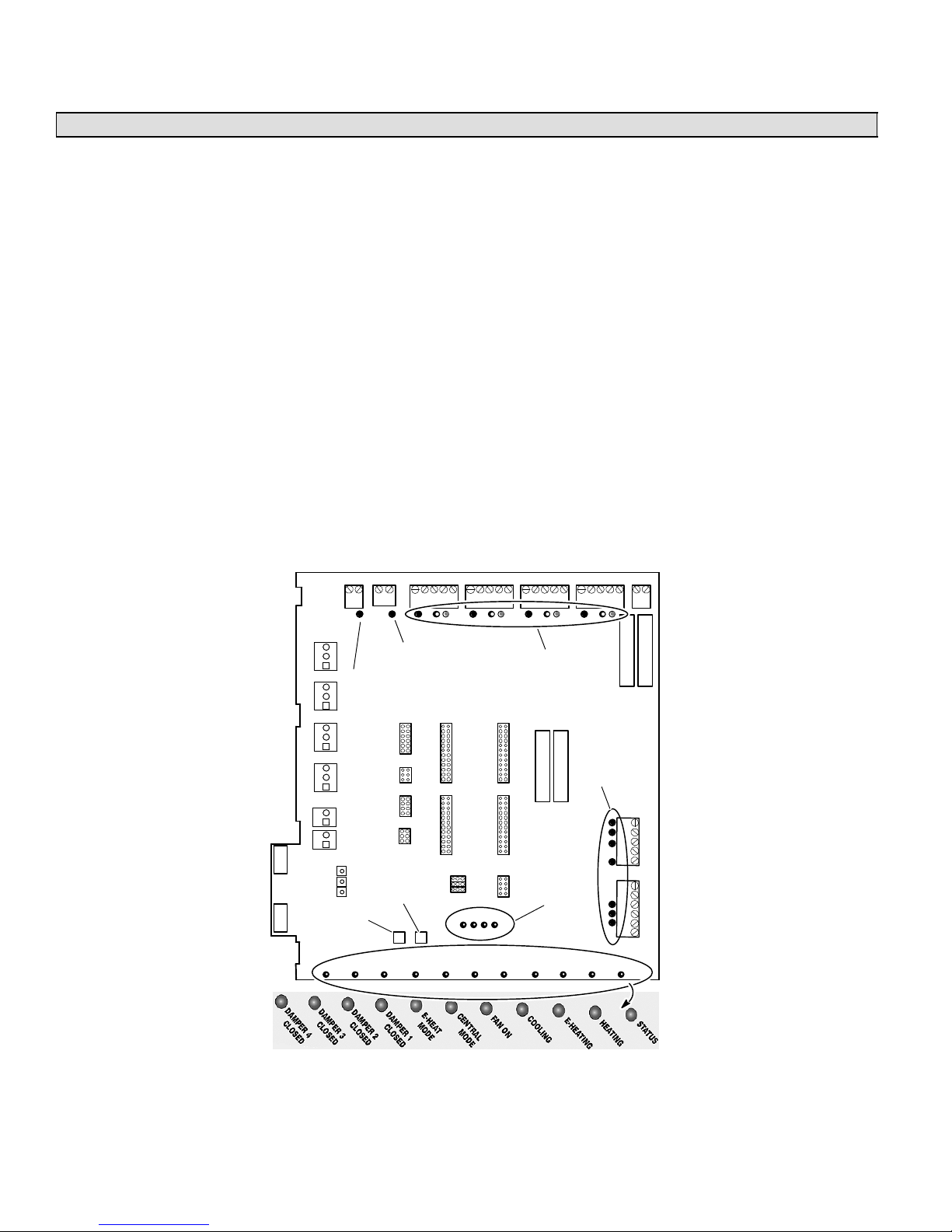
TROUBLESHOOTING
TROUBLESHOOTING
Operation & Troubleshooting Indicators
Zone Control Panel LEDs
The zone control system operation is indicated by light emitting diodes (LEDs) located on the zone control panel. In addition
to operating condition, the LEDs provide valuable information system troubleshooting. The LEDs (shown in figure 29) are
thermostat, diagnostic, and output status.
1. Thermostat LEDslocated along the upper edge of the zone control panel. Each zone has three LEDs to indicate a
call for heating or cooling: green (indicates a Y / compressor demand), red (indicates a W / heating demand) and amber
(indicates a G / indoor blower demand). These LEDs are labeled according to the zone and demand.
2. Diagnostic LEDsDiags 1, 2, 3, 4located near the bottom center of the the zone control panel. These LEDs aid the
technician in troubleshooting problems. When an error is detected, LEDs illuminate in a pattern. See Fault Recall and
Time Delay Override on page 55.
3. Output LEDslocated along the bottom of the zone control panel and near connection terminals. These red LEDs indicate the output status of dampers, furnace, outdoor unit, etc. When an output is powered or active, the corresponding
LED is illuminated.
4. Pressure Switch LEDLocated at the top left corner. Green LED illuminates when the heat pump pressure switch is
closed indicated normal pressures. The LED will be off when the pressure switch opens under abnormal or excessive
condensing pressure in the heat pump heating mode. Pressure switch is used only on heat pump systems.
5. Balance Point Sensor LEDLocated at the top left corner. Red LED illuminates when the balance point sensor is
closed indicating outdoor temperature is below the balance point sensor setting. Only used on dual fuel heat pump systems.
The LEDs are labeled according to output and function. For example, if Damper 1 LED is illuminated, it’s damper has
been signaled to close; when the LED is extinguished, it’s damper has been signaled to open, allowing air flow to that
zone.
PRESSURE
SWITCH LED
TIME DELAY
OVERRIDE
OUTDOOR THERMOSTAT /
BALANCE POINT LED
FAULT
RECALL
THERMOSTAT
LEDs
EQUIPMENT
OUTPUT LEDs
DIAGNOSTIC
LEDs
OUTPUT STATUS LEDs
Figure 29. System Indicators/Troubleshooting Devices
505023M 08/11
Page 54
Page 55

TROUBLESHOOTING
g
Fault Recall & Time Delay Override
When the Time Delay Override is pressed and held, the internal clock speeds up by a factor of 60. This overrides the current
time delay and permits the next event to occur. Table 9 identifies the time delays used by the system.
When the Fault Recall button is pressed and released (clicked), the fault codes are displayed (10 most recent). When the
fault recall button is pressed and held, the fault codes are erased. Each code will be displayed for 10 seconds starting with
the most recent code, then the next most recent, and so on. Pressing the button while recalling fault codes will bypass the
10-second timer and go right to the next fault code.
Use the Fault Recall button to observe diagnostic codes that will indicate either correct operation, or help checkout and
troubleshoot problems in the zone control system. Table 10 in the troubleshooting section (see page 56) identifies all diagnostic codes.
Press the button once while the system is operating. The system will respond by momentarily lighting all four DIAG LEDs
then displaying the error code, if an error code is stored in memory. This allows a visual check to verify that all four LEDs are
operational before displaying an error code.
Time Delays
Timers used in the Harmony IIIt system define delays which precede or follow a demand, depending on the type of function. The delays are used to control equipment connected to the system. Table 9 shows how the most noticeable delays are
used.
Table 9. Time Delays
Delay Time Function
Blower Off Delay (gas heat only) 3-1/2 min. Gas Furnace only. Delivers air into last zone called during cool down following heat demand.
Compressor Speed Change 4 min. Between low speed and high speed in order to make sure steady state is reached before stag-
Compressor Off Time 5 min. At end of demand. Equalizes pressure in refrigerant system and prevents short cycling.
Heat Staging (electric) 2 min. Between staging up or down (May stage faster to prevent overshoot/undershoot).
Heat Staging (gas) 3 min. Between staging up or down to achieve steady state.
Dual Fuel Furnace Lock-in Timer 3 hrs. Starts when system enters dual fuel furnace heating when the outdoor temperature is above
Damper Hold 3-1/2 min. This timer is defined as the amount of time to hold the last zone calling open past the thermostat
Autochangeover 20 min. When opposing demands are present, zone control system must work to satisfy current demand
Dual Fuel Autochangeover 20 min. When temperature is above balance point, heat pump will operate for 20 minutes before allowing
ing.
balance point. When operating within this 3-hour time, only the furnace is used for heating. Heat
pump will be tried again on the next call after this timer expires. Diagnostic LEDs 2, 3, and 4 will
flash when this timer is active.
call drop out. During this time, the panel will not energize the blower (except when a continuous
fan call exists); the controlled equipment will provide this signal. This is a non−adjustable timer
set at 210 seconds.
at least 20 min. If current demand is not satisfied after time has elapsed, system will changeover
and satisfy opposing demand. On and Off delays above will also apply.
gas furnace to take over heating demand.
Discharge Air Probe Checkout (All Systems)
The discharge air sensor is a temperature-dependent resistor; the higher the temperature, the lower the
resistance. To confirm the sensor is functioning, disconnect both sensor leads from the zone control panel.
Using a digital voltmeter (DVM) set to read resistance, touch the leads from the sensor to the probes of the
DVM.
Do not touch both probes with your fingersdoing so will produce a faulty reading. At 77°F, the resistance
of the sensor will be 10K ohm; at lower probe temperatures, expect higher resistance; at warmer probe
temperatures, expect lower resistance.
After reading the resistance at room temperature, warm the tip of the sensor by holding it in the palm of
your hand, and take another resistance reading. The resistance should be noticeably lower than the previous readin
The zone control system will monitor the operation of the probe and determine if a failure has occurred. The probe is an integral (but replaceable) part of the zone control system. The zone control system will indicate if the probe is operating improperly and needs to be
replaced. The discharge air temperature probe serves several purposes:
1. In cooling systems (and heat pump systems in cooling mode) the probe varies the speed of the compressor from high to low to off
in order to maintain a constant discharge air temperature and prevent coil freezing.
2. In gas heating systems, it is responsible for increasing the speed of the blower to the setting of the CFM jumpers after the discharge
air has warmed up to about 100_F. Also stages equipment up and down to control discharge air temperature.
3. In heat pump systems operating in the heating mode, the probe varies compressor speed and stages of auxiliary heat in order to
maintain a constant discharge air temperature.
.
Page 55
Temp.
ºF (ºC)
65 (18) 13476
70 (21) 11884
75 (24) 10501
80 (27) 9298
85 (29) 8249
90 (32) 7333
HARMONY IIIT ZONE CONTROL SYSTEM
Resistance
(ohms)
Page 56

TROUBLESHOOTING
Blower Speed Checkout
The indoor blower speed should vary as zone demand changes. The fan speed LED varies in brightness as the blower
varies in speed. The brighter the LED, the more CFM being delivered. Blower speed can also be viewed by attaching an
electronic voltmeter between DS and any C terminal on the zone control panel. While not a precise measurement, the voltmeter fluctuation indicates that the blower speed is changing.
1. Connect electronic voltmeter between DS and any C terminal on the zone control panel. Leave all field wiring in place.
2. Select DC volts scale.
3. Start zone heating or cooling checkout procedure.
4. Observe voltages:
D 22 volts DC = high speed (varies depending on input voltage at primary transformer).
D 11 volts DC (approx.) = medium speed 50% into adjustment band of blower.
D 0 volts DC = low speed or off.
All speeds in between are a percentage of 22VDC.
5. Also measure voltage at the indoor unit between DS and C. If the voltage is lower than the voltage measured at the
Harmony zone panel and/or the blower runs at a minimum fan speed, check and make sure C on the indoor unit is
connected to C on the zone panel transformer connection.
NOTE − G71MPP & SLP98 furnace models are equipped with an LED on the integrated control which displays blower airflow
in all modes of operation. See G71MPP & SLP98 installation instructions for additional information.
NOTE − CBX40UHV and CBX32MV Rev 06 have an LED display that will indicate the unit air volume. A" followed by the
number indicates the cfm. For example, A−2−0−0−5" indicates 2005 cfm.
NOTE − If blower operates only at the minimum cfm or will not ramp to zone air volume, check and make sure terminal C" on
the indoor unit terminal strip is connected to Harmony 24 VAC terminal C" (see figures 17 through 26).
NOTE − If blower hunts", check and make sure there is no connections on Y1 or Y2 on the indoor unit terminals strip (see
figures 17 through 26).
NOTE − Units without a 7−Segment LED will have a cfm" LED to indicate blower airflow. One blink of the LED is equal to
approximately 100 cfm; then it pauses and repeats. For example if the CFM indicator LED blinks 10 times this indicates
approximately 1000 cfm.
NOTE − Make sure DS on the Harmony board is connected to DS on the furnace/air handler terminal strip.
Troubleshooting using the Diagnostic LED Error Codes
When the zone control system finds a problem (error condition), it will turn on one or more of the diagnostic LEDs on the zone
control. These LEDs can be lit in several different patterns, each pattern corresponding to a different error condition. Table
10 shows each possible display pattern, a description of the error, and ways to correct the error.
Some of the errors found in table will cause a fail−safe or shutdown condition. The system will shutdown after the error is
present for about five seconds. During a shutdown condition, all dampers will open, there is no demand to the condensing
unit or furnace. Normal operation will resume five seconds after the error has been corrected.
The blower may run during a fail−safe condition after a heating demand. This is due to the operation of the integrated control
inside the furnace.
If a shutdown condition occurs while there is a call for cooling, a five−minute timer is initiated before cooling can be called for
again. The timer begins at the time of the shutdown condition and does not affect the response to, nor is affected by, a
heating demand.
Troubleshooting diagrams (figures 16, 22 28 [pages 21, 35, 47, respectively) identify common areas to check when troubleshooting specific equipment. The diagrams provide checkpoints related to connectivity and operation of system equipment.
Use these diagrams, along with installation information contained throughout this manual, to identify and correct problems.
Table 10. Diagnostics Codes
(0−off;1−on)
Code
Diag LED
#
0 0000 Normal
1 1000 Insufficient
2 0100 Defrost time
1234
Fault
Indicated
operation
cooling
> 20 minutes
Remedy
No remedial action required.
Occurs when there is a call for cooling and the Discharge Air Sensor does
not sense a decrease in supply air temperature indicating the cooling is not
functioning properly.
The defrost board should never allow a defrost for greater than 20 minutes. If
this error occurs, check the outdoor unit to see if it is stuck in defrost mode.
The zone control system will use the backup heat during this error and not
the heat pump.
table continued on next page
Fail-safe
(System
Shut Down)
No
No
505023M 08/11
Page 56
Page 57

TROUBLESHOOTING
(0−off;1−on)
Code
Diag LED
#
3 1100 Unsteady
4 0010 Defrost while
5 1010 Discharge Air
6 0110 Zone air
7 111 0 Open or
8 0001 Simultaneous
9 1001 Open pressure
10 0101 Insufficient
11 1101 DAS sensed
12 0011 Multiple jumper
13 0111 Dual−fuel
1234
Fault
Indicated
thermostat
input
gas heat
selected
Sensor (DAS)
detects high
heating
temperature
jumper not
selected
shorted DAS
heat and cool
call from same
thermostat
switch (heat
pump
systems only)
heating
frozen coil
selection
furnace use
lock−in
This error occurs when a thermostat changes state repeatedly and rapidly,
indicating that the thermostat is making intermittent contact and needs attention. The offending thermostat will be ignored for 4 minutes after the zone
control system detects the problem. After 4 minutes if the signal from the
thermostat is steady again, it will be recognized by the zone control system.
Disconnect thermostats until error goes away. This will identify the source of
bad input. If error remains after all inputs have been disconnected, replace
zone control panel.
System detected defrost signal at W1−Def terminal block while the jumper is
selected for the furnace. May be caused by:
S Wrong selection for INDOOR UNIT jumper.
S OUTDOOR UNIT terminal block misfired.
S Zone control system failure.
Check unit installation instructions for correct wiring. If no signal is present at
W1, then replace zone control panel.
This condition may occur any time the discharge probe senses air warmer
than 160_F for furnace or 135_F for heat pump. If system is in zone mode
when this code is set, the system continues in zone mode, shuts off equipment, and runs continuous blower to satisfy demand. The heat pump or furnace will remain off for a minimum of 5 minutes and until the DAS senses
130_F.
Add more air to zone or redistribute zones to divide air more evenly.
1) Air selected for fewer than two zones or, 2) No air is selected for zone 1
or, 3) If a zone air selection jumper is left off of a zone that issues a heat or
cool demand. In this case the system will assume that a PIAB of 100 is required to service the zone.
Make a zone air jumper selection. If jumpers are in place, replace the zone
control panel.
If system is operating, system will be forced into central mode. The compressor will cycle from high to off in cooling. The compressor will cycle from high
to off in heating. The furnace will operate normally in gas heat.
Replace discharge probe. If error persists, replace zone control panel.
(Or inconsistent thermostat signals) Make sure the thermostats are correctly
connected to the zone control panel. If error persists after you check the
thermostats and jumper selections, try another thermostat model or brand.
Demand will be ignored from the zone sending bad signals. See Table 9.
Displayed when the pressure switch opens and does not necessarily mean
there is anything wrong. However, try increasing the air delivered to the
smallest zone. An open pressure switch will stage the heat pump down to 1st
stage only, if after 90 seconds the switch does not close, the heat pump is
shut off and backup heat is used to satisfy the call. Green Pressure switch
LED on zone panel will be off.
Occurs when there is a call for heating and the Discharge Air Sensor does
not sense a increase in supply air temperature indicating the heating is not
functioning properly.
Indicates discharge air temperature sensed by discharge air sensor drops
below 45 degrees during the cooling mode. When sensed, the condensing
unit will stop and as long as the cooling demand is present the ID blower will
continue to run until the 5 minute timed off timer expires and the discharge
air sensor senses 55_F.
Each jumper block on zone control panel is allowed only one jumper, except
for the system setup block. Remove extra jumper.
Heat pump was not able to maintain desired discharge air temperature; furnace will be used to satisfy heat calls for the next 3 hours. After 3 hours, the
heat pump will be used again.
Fail-safe
(System
Shut Down)Remedy
No
Ye s
No
No
No
No
No
No
No
No
No
Page 57
HARMONY IIIT ZONE CONTROL SYSTEM
Page 58
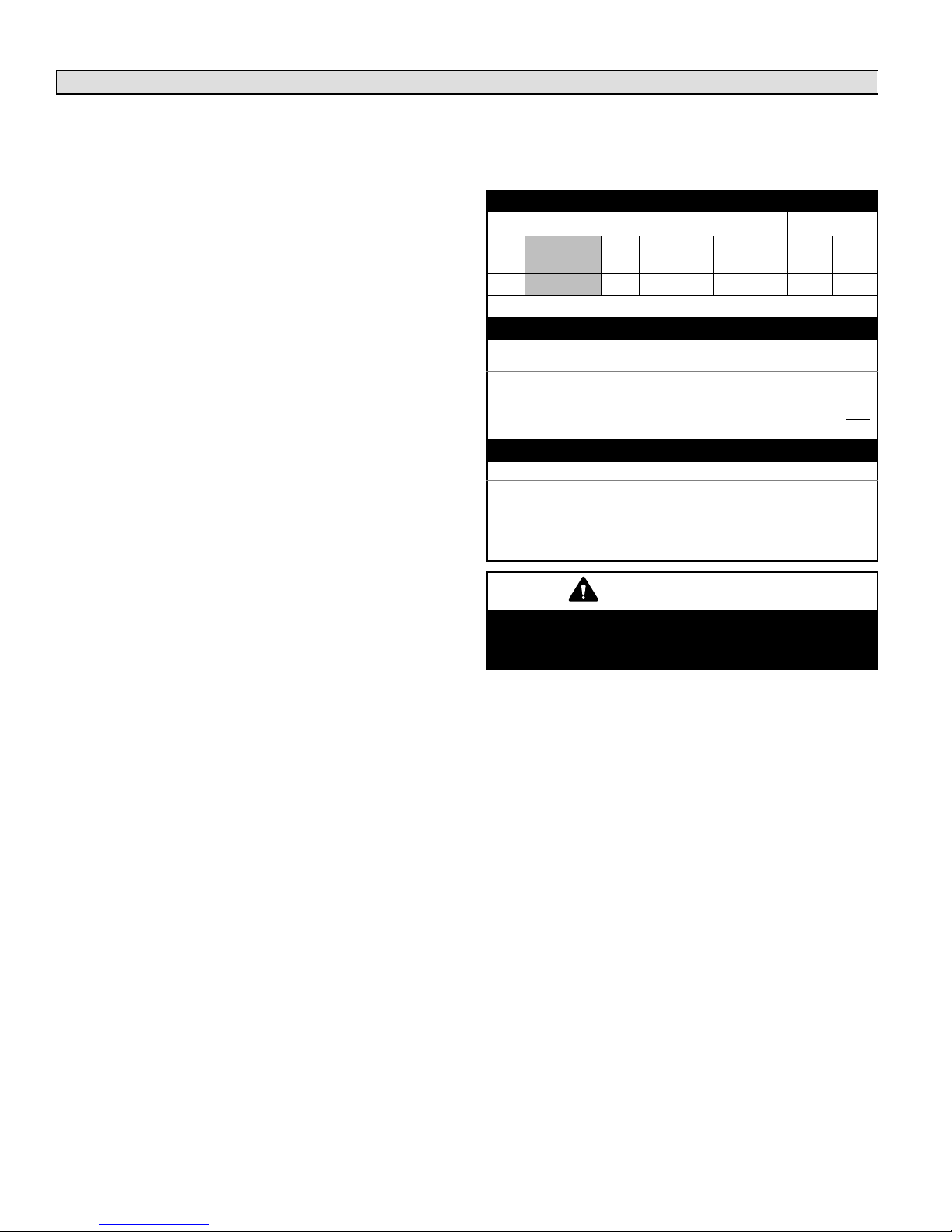
TROUBLESHOOTING
Troubleshooting Air Delivered By Blower
The actual CFM delivered to each zone will be determined
by the zone control system settings, blower motor control
board settings, zone thermostat demand status (calling for
heating, cooling, continuous fan, or no demand [zone
damper closed]), and the air distribution system’s duct
size.
When the zone control system is set for a particular zone,
heating reduction jumper, and/or continuous air reduction
settings determine the total CFM available from the unit as
follows:
1. Determine Total Unit PIABUsing the formula in
Table 11, calculate the Total Percent into Adjustment
Band. This illustrates the percentage into the adjustment band that the motor runs when more than one
zone is calling for conditioning.
2. Determine Total CFM DeliveredContinuing from
the previous example and assumptions, and using the
formula in Table 11, calculate the total CFM delivered.
The max. and min. CFM values used in the formula
should correspond to the jumper settings on the blower control board. This value represents the volume of
air received if all zones were calling for cooling.
3. Determine heating PIAB and total heating air CFM
delivered during a heating callCalculate these totals using the formulas and examples in Table 12.
5. Determine total air delivered during a continuous
blower callCalculate these totals using the formulas and examples in Table 13.
Table 11. Determine total PIAB & total CFM delivered
Example values
Jumpers CFM
Cont. Air
Zn1 Zn2 Zn3 Zn4
30% 10% 20% OFF 25% 20% 720 2200
Gray zones are calling.
Reduction
Heating
Air Red.
Min. Max.
Total PIAB Formula
(Sum of calling zones 1 to 4
jumper positions)
1. Using example values above, find Total PIAB:
Jumper positions .10 +.20 .30. . . . . . . . . . . . . . . . . . . . . . . . . . . . .
(# of Calling zones minus 1) divided by 3 (2−1)/3 +.33. . . . . . . . . .
Total (motor runs 63% into adjustment band of motor) . 63. . . . . .
(# of zones calling − 1)
+
3
Total CFM Formula
Total PIAB x (CFM max. − CFM min.) + (min. CFM)
2. Then find Total CFM:
Total PIAB from step 1. .63. . . . . . . . . . . . . . . . . . . . . . . . . . . . . .
CFM max. − CFM min. (2220−720) x1500. . . . . . . . . . . . . . . . . . . . . .
CFM into adjustment band 945. . . . . . . . . . . . . . . . . . . . . . . . . . . . .
Total CFM (CFM min + CFM into adjustment band) 1665. . . . . . . .
IMPORTANT
4. Check "CFM" LED or 7−Segment LED on indoor unit
to obtain approximately CFM the indoor unit is operating at.
If any blower speed settings (furnace or air handler)
are changed, the zone control PIAB calculations
must be performed again to ensure proper airflow.
505023M 08/11
Page 58
Page 59

Troubleshooting Air Delivered By Blower (continued)
Table 12. Determine total heating CFM delivered
Example values
Jumpers CFM
Cont. Air
Zn1 Zn2 Zn3 Zn4
30% 50% 40% OFF 25% 20% 720 2200
Gray zones are calling.
Reduction
Heating
Air Red.
Min. Max.
Total PIAB Formula
(Sum of calling zones 1 to 4
jumper positions)
(# of zones calling − 1)
+
3
1. Using example values above, find Total PIAB:
Jumper positions .30 +.40 .70. . . . . . . . . . . . . . . . . . . . . . . . . . . . .
(Calling zones minus 1) divided by 3 (2−1)/3 +.33. . . . . . . . . . . . .
Total (use sum or 1.00, whichever is less) 1.03 *1.00. . . . . . . . . . .
*Blower cannot support 103%; uses 100%
Heating PIAB Formula
Tot al P IAB x (1 − Heating air reduction setting)
2. Then find Heating PIAB:
Total PIAB from step 1 1.00. . . . . . . . . . . . . . . . . . . . . . . . . . . . . . .
(1−Heating air reduction setting) (1.00−.20) x.80. . . . . . . . . . . . . . .
Total Heating PIAB .80. . . . . . . . . . . . . . . . . . . . . . . . . . . . . . . . . . .
Total Heating CFM Formula
Heating PIAB x (CFM Max. − Min.) + (Min. CFM)
3. Then find Total Heating CFM:
Heating PIAB from step 2 .80. . . . . . . . . . . . . . . . . . . . . . . . . . . . .
CFM max. − CFM min. (2220−720) x1500. . . . . . . . . . . . . . . . . . . . . .
Subtotal 1200. . . . . . . . . . . . . . . . . . . . . . . . . . . . . . . . . . . . . . . . . . . .
Min CFM +720. . . . . . . . . . . . . . . . . . . . . . . . . . . . . . . . . . . . . . . . . . .
Total Heating CFM 1920. . . . . . . . . . . . . . . . . . . . . . . . . . . . . . . . . . .
Table 13. Determine total continuous CFM delivered
Example values
Zn1 Zn2 Zn3 Zn4
30% 50% 40% OFF 25% 20% 720 2200
Gray zones are calling.
Total PIAB Formula
1. Using example values above, find Total PIAB:
Jumper positions (.30+.50+.40) 1.20. . . . . . . . . . . . . . . . . . . . . . . .
(Calling zones minus 1) divided by 3 (3−1)/3 +. 66. . . . . . . . . . . . .
Total (use sum or 1.00, whichever is less) 1.86 *1.00. . . . . . . . . . .
*Blower cannot support 186%; uses 100%
Continuous Air PIAB Formula
2. Then find Continuous Air PIAB:
Total PIAB from step 1. 1. . . . . . . . . . . . . . . . . . . . . . . . . . . . . . .
x (1−Continuous air reduction setting) (1.00−.25) x.75. . . . . . . . . .
Total Continuous Air PIAB .75. . . . . . . . . . . . . . . . . . . . . . . . . . . . .
Total Continuous CFM Formula
3. Then find Total Continuous Air CFM:
Continuous Air PIAB from step 2. .75. . . . . . . . . . . . . . . . . . . . . .
CFM max. − CFM min. (2220−720) x1500. . . . . . . . . . . . . . . . . . . . . .
Subtotal 1125. . . . . . . . . . . . . . . . . . . . . . . . . . . . . . . . . . . . . . . . . . . .
Min CFM +720. . . . . . . . . . . . . . . . . . . . . . . . . . . . . . . . . . . . . . . . . . .
Total Continuous Air CFM 1845. . . . . . . . . . . . . . . . . . . . . . . . . . . . .
TROUBLESHOOTING
Jumpers CFM
Cont. Air
Reduction
(Sum of calling zones 1 to 4
jumper positions)
Tot al P IAB x (1 − continuous air reduction setting)
Continuous air PIAB x (CFM max. − CFM min.) + (min. CFM)
Heating
Air Red.
(# of zones calling − 1)
+
Min. Max.
3
Page 59
HARMONY IIIT ZONE CONTROL SYSTEM
Page 60
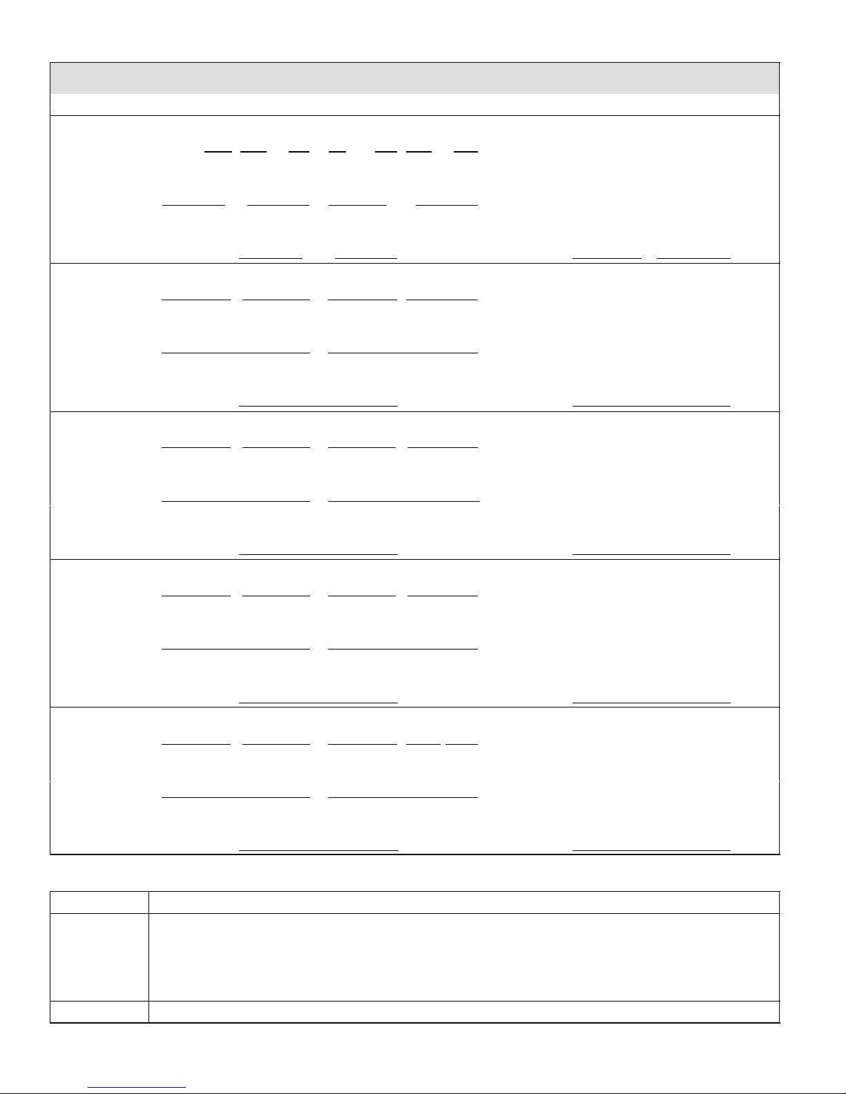
PIAB Calculation Worksheet
PIAB Calculation Worksheet
PIAB = [(Required CFM − Minimum CFM) / (Maximum CFM − Minimum CFM)] * 100
Sample CFM ' Required Minimum Maximum Minimum
Sample PIAB = ([___920 − 450 ] / [ 2000 − 450 ]) x 100
==
bb
Sample PIAB = ([ 470 ] / [ 1550 ]) x 100
=
b
Sample PIAB = [ 0.303 ] x 100 = 30 %
Zone 1 CFM ' Required Minimum Maximum Minimum
ZONE 1 PIAB = ([ − ] / [ − ]) x 100
==
bb
ZONE 1 PIAB = ([ ] / [ ]) x 100
=
b
ZONE 1 PIAB = [ ] x 100 = %
Zone 2 CFM ' Required Minimum Maximum Minimum
ZONE 2 PIAB = ([ − ] / [ − ]) x 100
==
bb
ZONE 2 PIAB = ([ ] / [ ]) x 100
=
b
ZONE 2 PIAB = [ ] x 100 = %
Zone 3 CFM ' Required Minimum Maximum Minimum
ZONE 3 PIAB = ([ − ] / [ − ]) x 100
==
bb
ZONE 3 PIAB = ([ ] / [ ]) x 100
=
b
ZONE 3 PIAB = [ ] x 100 = %
Zone 4 CFM ' Required Minimum Maximum Minimum
ZONE 4 PIAB = ([ − ] / [ − ]) x 100
==
bb
ZONE 4 PIAB = ([ ] / [ ]) x 100
=
b
ZONE 4 PIAB = ( ) x 100 = %
Date Revision description
01−2011 G71, SLP98 Furnace support added.
CBX32, CBX40 (non icomfortt) support added.
Clarifications requested by Applications, Field, and Training groups.
Added installation worksheets
Clarification of zone control jumper usage.
07−2011 Add SL280V, EL296V Furnace support added. (reformatted)
505023M 08/11
REVISION HISTORY
Page 60
 Loading...