

Page 1
ENGINEERING DATA
FOR VARIABLE AIR VOLUME HEATING/COOLING SYSTEMS
Harmony
four separate heating/cooling zones utilizing a single indoor unit (G21V/GSR21V or
CB21/CBH21) and single outdoor unit (HS14 or HP21 two-speed). A single speed outdoor unit may be used for up to two zone applications. Two-speed outdoor unit may
be used for two, three or four zone applications. The system consists of the Harmony
control center, discharge air sensor, Harmony control panel, master thermostat and
duct mounted zone dampers with a thermostat in each zone. The zone dampers are
automatically controlled to supply air flow only to zones with a thermostat demand.
At the same time, the variable speed motor (VSM) in the G21V/GSR21V furnace or
CB21/CBH21 blower coil unit automatically adjusts the air volume to the zones as required. Because of the VSM motors’ ability to vary system air volume as required, no
bypass damper is required. Individual air volumes for heating or cooling are available
to each zone. Dampers are available in either round or rectangular configuration. Each
zone is sized for the heating/cooling load. Damper operation and blower air volume
is controlled by the control center. The Harmony system saves energy by allowing
temperature setback in unoccupied areas while maintaining comfort in occupied
areas. System also results in lower equipment costs by eliminating the need for two
separate heating/cooling systems. The Harmony Zone Control System may be used
in conjunction with the FM21 Heat Pump Control System and may also be used in
Smarthouse applications.
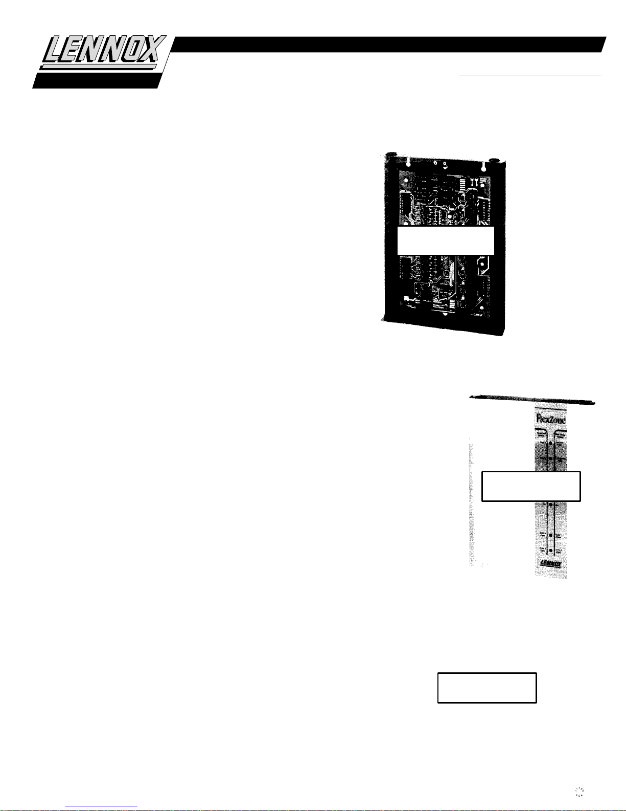
Control Center
operate the system. Control center cabinet is constructed of heavy gauge steel with a
enamel paint finish and removeable latching cover. Solid-state circuit board features:
low voltage output terminals for controlling up to four zones and indoor and outdoor
unit connections. Also has low voltage input terminals for up to four zone thermostats,
control panel, zone damper transformer, pressure switch and discharge air sensor.
Board also has jumper selectors for “Zone Air Volume Selection” (25-95%), “Heating
Air Reduction” (0%, 20% or 40%), “Continuous Air Reduction” (0%, 50% or 75%) and
“Discharge Air Temperature” (+ or – 5F heat or cool). LED’s on circuit board indicate
“Heating” (Red), “Cooling” (Green) for each zone and “Reversing Valve” (Amber).
Additional LED’s (Red) on board indicate “Zone Damper Operation”, “Indoor Unit Operation”, “Blower Operation” and “Outdoor Unit Operation”. Four diagnostic LED’s are
furnished as an aid in servicing system. Board stores last two diagnostic codes for easy
servicing. Built-in time delay function prevents short cycling of system. Holes for
mounting are furnished and electrical inlets are provided in top, bottom and rear of panel. Dimensions: 13-1/4” x 10” x 1-3/4”. Power requirements: 24VAC. Control center is
powered by indoor unit transformer. Shipping weight: 6 lbs.
Control Panel
Off” control mode selection, “Cool”, “Auto” or “Heat” mode selection and “Auto“ or
“On” fan control for continuous or intermittent blower operation. LED indicators show
selected features at a glance. Panel is constructed of high impact Cycolac. Dimensions:
3-1/2” x 4-3/4” x 1-5/16”.
Discharge Air Sensor Probe
contains three sensors that monitor air temperature in the supply air stream. Sensors
send a temperature average to the control center to control blower motor speed.
System Equipment Data
pump) for system equipment selection. For G21V/GSR21V series furnace data, see
section Heating Units — Gas. For HS14 series two-speed or other single speed condensing units data, see Cooling Units — Condensing Units section. For add-on evaporator coil unit data, see section, Cooling Units — Coils-Blower Coil Units. For HP21 series two-speed or other single speed heat pump outdoor units data, see Heat Pumps
— Matched Remote Systems section. For CB21/CBH21 blower-coil unit data, see section, Cooling Units — Coils-Blower Coil Units. For EMD14-65 or EMD14M-65 Economizer dampers, see Accessories section.
Sequence of Operation
— a “Central” control mode and a “Zone” control mode.
In the “central” mode, heating or cooling selection and temperature demand are con-
trolled by the zone 1 (master) thermostat, all dampers remain open at mechanically
preset openings and blower is controlled by the central control board (total zone air
volume), delivering air to all zones.
In the “zone” mode, heating or cooling selection is controlled by the control panel (or by
the individual zone thermostats if system is set for auto-changeover), temperature demand is controlled by the individual zone thermostats, zone dampers route air to appropriate zones and blower air volume is adjusted according to central control jumper
setting and number of zones operating.
Individual air volume for each zone is preset at the control center and may be adjusted
from 25% to 95% actual air volume. During heating mode, Heating Air Reduction jumpers
allow a lower heating air volume to be selected (0%, 20% or 40% reduction of cooling air
volume). During continuous (“On”) blower operation, Continuous Air Reduction jumpers allow 0%, 50% or 75% air volume reduction. All dampers remain open if there is
no demand from thermostats.
NOTE — Specifications, Ratings and Dimensions subject to change without notice. 1993 Lennox Industries Inc.
II
Zone Control System
— Control center (16J95) contains all necessary relays and controls to
— Touch sensitive panel (16J96) features: “Zone”, “Central” or “System
— See flow charts on page 4 (gas heat) and page 5 (heat
— Two modes of operation are available at the control panel
— Harmony II system is designed to provide up to
— Probe (16J98) is required for field installation. Probe
HARMONY
II
ZONE CONTROL SYSTEM
ZONE SYSTEM
CONTROL
(cover in place)
POSITION
ONLY
CENTER
ACCESSORIES
HARMONY
Bulletin #480182
February 1993
Supersedes
February 1992
ZONE SYSTEM
CONTROL
CENTER
(cover removed)
POSITION
ONLY
POSITION
ONLY
ZONE SYSTEM
CONTROL
PANEL
II
Page 2
OPTIONAL EQUIPMENT (Must Be Ordered Extra)
RECTANGULAR
ZONE DAMPER
ROUND
ZONE DAMPER
Master (Zone 1) Thermostat (Optional)
mable thermostat for zone 1 master thermostat. See flowcharts on pages 4 and 5 for
recommended thermostats. Also see Thermostats bulletin in Accessories section.
Zone Thermostats (Optional)
zone thermostats. Also see Thermostats bulletin in Accessories section.
Round Zone Damper (Optional) — Round damper is constructed of heavy gauge galvanized steel. Damper shell is furnished with one straight end and one crimped end
for ease of duct connection. Damper blade rotates smoothly in nylon bearings. Adjustable blade stop is furnished on damper blade for system balancing. Damper features
factory installed, heavy duty, synchronous motor with spring return open. Heavy duty
steel gearing provides long motor life. Damper springs open in case of power failure.
See damper specifications table for sizes, air resistance and shipping weights. Power
requirements: 24 VAC.
— See flowcharts on pages 4 and 5 for recommended
Rectangular Zone Damper (Optional)
gauge aluminum and stainless steel. Damper is a slip-in, opposed blade type with duct
mounting plate on one end for ease of duct connection. Damper rotates smoothly in
nylon bearings. A rubber blade stop is furnished for installation on damper blade if
system balancing is required. Damper features factory installed, heavy duty, synchronous motor with spring return open. Heavy duty steel gearing provides long motor life.
Damper springs open in case of power failure. See damper specifications table for
sizes, air resistance and shipping weights. Power requirements: 24 VAC.
Pressure Switch (Required for Heat Pump Operation)
quired for proper system operation in heat pump applications.
Transformer (Optional)
flowcharts on pages 4 and 5.
— Transformer is required for operation of zone dampers. See
— Lennox recommends the use of a program-
— Rectangular damper is constructed of heavy
— Pressure Switch (21J18) is re-
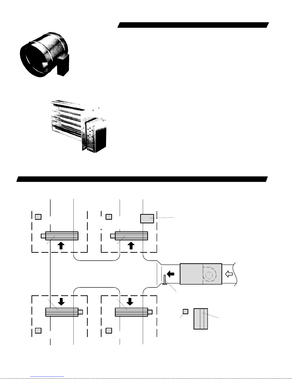
TYPICAL SYSTEM LAYOUT
ZONE 2 ZONE 1
ZONE 2
THERMOSTAT
ZONE
DAMPER
ZONE
DAMPER
ZONE 1
THERMOSTAT
(Master Thermostat)
ZONE
DAMPER
ZONE
DAMPER
SUPPLY
AIR
HARMONY
CONTROL
PANEL
HEATING/
COOLING
UNIT
DISCHARGE
AIR SENSOR
RETURN
AIR
ZONE 3
THERMOSTAT
ZONE 3 ZONE 4
ZONE 4
THERMOSTAT
—2—
ZONE
DAMPER
TRANSFORMER
HARMONY
CONTROL
CENTER
Page 3

DAMPER SPECIFICATIONS
ROUND ZONE DAMPERS
Catalog
No.
77G99 6 100 .04 2
78G00 8 150 .03 4
78G01 10 200 .02 6
78G02 12 350 .03 8
78G03 14 400 .02 10
Dimensions
Dia. (in.)
Air
Volume
(cfm)
50 .01
110 .05
100 .02
210 .05
100 .01
325 .05
200 .02
460 .05
200 .01
640 .06
Total
Resistance
(In. wg.)
Shipping
FIELD WIRING
Weight
(lbs.)
RECTANGULAR ZONE DAMPERS
Catalog
No.
78G04 10 X 8 200 .02 4
78G05 12 X 8 240 .02 3
78G06 14 X 8 350 .03 3
78G07 16 X 8 395 .03 4
78G08 18 X 8 375 .02 4
78G09 20 X 8 415 .02 4
Dimensions
W x H (in.)
Air
Volume
(cfm)
100 .01
325 .05
120 .01
395 .05
200 .02
460 .05
225 .02
520 .05
185 .01
600 .06
210 .01
665 .06
Total
Resistance
(In. wg.)
Shipping
Weight
(lbs.)
ZONE 1 ZONE 2
THERMOSTAT
(MASTER)
ZONE
SYSTEM
CONTROL
PANEL
ZONE
DAMPER
POWER
TRANSFORMER
ZONE DAMPER
A
D
B
B
*ZONE 3 *ZONE 4
THERMOSTAT
(Optional)
A
B
ZONE
DAMPER
A — Three wire low voltage (gas heat systems) — 18 ga. minimum
Five wire low voltage (heat pump systems) — 18 ga. minimum
B — Two wire low voltage — 18 ga. minimum
C — Seven wire low voltage — 18 ga. minimum
D — Six wire low voltage — 18 ga. minimum
E — Two wire low voltage (single speed condensing unit) 18 ga. minimum
Three wire low voltage (two speed condensing unit) 18 ga. minimum
Four wire low voltage (single speed heat pump outdoor unit) 18 ga. minimum
Five wire low voltage (two speed heat pump outdoor unit) 18 ga. minimum
F — Two wire low voltage (discharge air sensor) 18 ga. minimum
G — Two wire low voltage — pressure switch (heat pump only) — 18 ga. minimum
F
COIL
G
G21V /
GSR21V
FURNACE
OR
CB/CBH21
BLOWER
COIL UNIT
ZONE
SYSTEM
CONTROL
CENTER
C
E
B
* NOTE — Zone 3 and Zone 4 Not Available
With Single Speed Outdoor Unit.
— Field Wiring Not Furnished —
—3—
A
THERMOSTAT
(Optional)
ZONE
DAMPER
B
CONDENSING
UNIT
OR
HEAT PUMP
OUTDOOR
UNIT
A
THERMOSTAT
(Optional)
ZONE
DAMPER
Page 4

CONTROL SYSTEM COMPONENT SELECTION (Gas Heat/Condensing Unit Systems)
—4—
STOP
START
UP-FLO
HORIZONTAL OR
DOWN-FLO
TWO ZONES
TWO, THREE
OR FOUR
ZONES
SINGLE SPEED
CONDENSING
UNIT
HS19
HS22
HS23
TWO-SPEED
CONDENSING
UNIT
HS14
UP-FLO
FURNACE
G21V SERIES
HORIZONTAL OR
DOWN-FLO
FURNACE
GSR21V SERIES
GAS
HEAT/
CONDENSING
UNIT
ROUND
ZONE DAMPERS
(See Below)
RECTANGULAR
ZONE DAMPERS
(See Below)
NONO
DAMPER
TRANSFORMER
up to 5 Dampers
(87344) 45VA
ECONOMIZER
DAMPERS
EMD14-65 or
EMD14M-65
ECONOMIZER
DAMPERS
WIRING HARNESS
120 volts (14H57)
ELECTRONIC AIR
CLEANER
EAC12-14
(69H71)
EAC12-20
(69H72)
ZONE
THERMOSTAT
(One Required
For Each
Additional
Zone)
(See Below)
ZONE 1
MASTER
THERMOSTAT
(See Below)
CONTROL
PANEL
(16J96)
CONTROL
CENTER
(16J95)
DISCHARGE AIR
SENSOR PROBE
(16J98)
RECOMMENDED MASTER THERMOSTATS
(For a complete selection of alternate thermostats, see
Thermostats Bulletin in Accessories section.)
Catalog
Description No.
*1 Htg.-1 Clg. 5-1-1 Day Programmable 27H31. . . . . . . . . . . .
1 Htg.-1 Clg. 5-2 Day Programmable 18H10. . . . . . . . . . . . . . . .
1 Htg.-1 Clg. 7 Day Programmable 18H11. . . . . . . . . . . . . . . . .
*Recommended master thermostat.
RECOMMENDED ZONE THERMOSTATS
(For a complete selection of alternate thermostats, see
Thermostats Bulletin in Accessories section.)
Catalog
Description No.
*1 Htg.-1 Clg. Electro-Mech. w/ subbase (Off-Auto) 86H23. .
**1 Htg.-1 Clg. 5-2 Day Programmable 18H10. . . . . . . . . . . . .
1 Htg.-1 Clg. Electro-Mech. w/ subbase 12F99. . . . . . . . . . . . . . .
Subbase for 12F99 (Off-Auto) 13F18. . . . . . . . . . . . . . . . .
1 Htg.-1 Clg. Electro-Mech. w/ subbase 38234. . . . . . . . . . . . .
1 Htg.-1 Clg. Electro-Mech. w/ subbase 17G17. . . . . . . . . . . . .
1 Htg.-1 Clg. Electro-Mech. w/ subbase 17G18. . . . . . . . . . . . .
1 Htg.-1 Clg. Electro-Mech. w/ subbase 78H22. . . . . . . . . . . . .
1 Htg.-1 Clg. Electro-Mech. 12F99. . . . . . . . . . . . . . . . . . . . . . . .
Subbase for 12F99 13F17. . . . . . . . . . . . . . . . . . . . . . . . . . .
*Recommended electro-mechanical zone thermostat.
**Recommended programmable zone thermostat.
ZONE DAMPERS
ROUND DAMPERS
Catalog
Description No.
6” dia. 77G99. . . . . . . . . . . . . . . . . . . . . . . . . . . . . . . . . . . . . . . . . .
8” dia. 78G00. . . . . . . . . . . . . . . . . . . . . . . . . . . . . . . . . . . . . . . . . .
10” dia. 78G01. . . . . . . . . . . . . . . . . . . . . . . . . . . . . . . . . . . . . . . . . .
12” dia. 78G02. . . . . . . . . . . . . . . . . . . . . . . . . . . . . . . . . . . . . . . . . .
14” dia. 78G03. . . . . . . . . . . . . . . . . . . . . . . . . . . . . . . . . . . . . . . . . .
RECTANGULAR DAMPERS
Catalog
Description No.
10” x 8” 78G04. . . . . . . . . . . . . . . . . . . . . . . . . . . . . . . . . . . . . . . . .
12” x 8” 78G05. . . . . . . . . . . . . . . . . . . . . . . . . . . . . . . . . . . . . . . . .
14” x 8” 78G06. . . . . . . . . . . . . . . . . . . . . . . . . . . . . . . . . . . . . . . . .
16” x 8” 78G07. . . . . . . . . . . . . . . . . . . . . . . . . . . . . . . . . . . . . . . . .
18” x 8” 78G08. . . . . . . . . . . . . . . . . . . . . . . . . . . . . . . . . . . . . . . . .
20” x 8” 78G09. . . . . . . . . . . . . . . . . . . . . . . . . . . . . . . . . . . . . . . . .
Page 5

CONTROL SYSTEM COMPONENT SELECTION (Heat Pump Systems)
—5 —
STOP
START
UP-FLO OR
DOWN-FLO
HORIZONTAL
TWO ZONES
TWO, THREE
OR FOUR
ZONES
SINGLE SPEED
OUTDOOR UNIT
HP19
HP22
HP23
UP-FLO OR
DOWN-FLO
BLOWER COIL
CB21 SERIES
HORIZONTAL
BLOWER COIL
CBH21 SERIES
HEAT PUMP
SYSTEM
PRESSURE
SWITCH
(21J18)
ROUND
ZONE DAMPERS
(See Below)
RECTANGULAR
ZONE DAMPERS
(See Below)
NONO
DAMPER
TRANSFORMER
up to 5 Dampers
(87344) 45VA
ECONOMIZER
DAMPERS
EMD14-65 or
EMD14M-65
ECONOMIZER
DAMPERS
WIRING HARNESS
120 volts (14H57)
ELECTRONIC AIR
CLEANER
EAC12-14
(69H71)
EAC12-20
(69H72)
ZONE
THERMOSTAT
(One Required
For Each
Additional
Zone)
(See Below)
ZONE 1
MASTER
THERMOSTAT
(See Below)
CONTROL
PANEL
(16J96)
CONTROL
CENTER
(16J95)
DISCHARGE AIR
SENSOR
(16J98)
TWO-SPEED
OUTDOOR UNIT
HP21
RECOMMENDED THERMOSTATS
(For a complete selection of alternate thermostats,
see Thermostats Bulletin in Accessories section.)
Catalog
Description No.
*2 Htg.-1 Clg. 7 Day Programmable 91H72. . . . . . . . . . . . . . . .
3 Htg.-2 Clg. 7 Day Programmable 18H13. . . . . . . . . . . . . . . . .
2 Htg.-2 Clg. Digital Setpoint 43H98. . . . . . . . . . . . . . . . . . . . . . .
2 Htg.-1 Clg. 5-1-1 Day Programmable 27H30. . . . . . . . . . . . . .
**2 Htg.-1 Clg. Electro-Mechanical w/ Subbase 51H40. . . . . .
*Recommended programmable master thermostat or zone thermostat.
**Recommended electro-mechanical zone thermostat.
ZONE DAMPERS
ROUND DAMPERS
Catalog
Description No.
6” dia. 77G99. . . . . . . . . . . . . . . . . . . . . . . . . . . . . . . . . . . . . . . . . .
8” dia. 78G00. . . . . . . . . . . . . . . . . . . . . . . . . . . . . . . . . . . . . . . . . .
10” dia. 78G01. . . . . . . . . . . . . . . . . . . . . . . . . . . . . . . . . . . . . . . . . .
12” dia. 78G02. . . . . . . . . . . . . . . . . . . . . . . . . . . . . . . . . . . . . . . . . .
14” dia. 78G03. . . . . . . . . . . . . . . . . . . . . . . . . . . . . . . . . . . . . . . . . .
RECTANGULAR DAMPERS
Catalog
Description No.
10” x 8” 78G04. . . . . . . . . . . . . . . . . . . . . . . . . . . . . . . . . . . . . . . . .
12” x 8” 78G05. . . . . . . . . . . . . . . . . . . . . . . . . . . . . . . . . . . . . . . . .
14” x 8” 78G06. . . . . . . . . . . . . . . . . . . . . . . . . . . . . . . . . . . . . . . . .
16” x 8” 78G07. . . . . . . . . . . . . . . . . . . . . . . . . . . . . . . . . . . . . . . . .
18” x 8” 78G08. . . . . . . . . . . . . . . . . . . . . . . . . . . . . . . . . . . . . . . . .
20” x 8” 78G09. . . . . . . . . . . . . . . . . . . . . . . . . . . . . . . . . . . . . . . . .
 Loading...