

Page 1
HEARTH PRODUCTS
KITS AND ACCESSORIES
INSTALLATION INSTRUCTIONS FOR THE REFLECTIONS REMOTE CONTROL
REPLACEMENT KIT (KIT NUMBERS: H1454 AND H6977)
GENERAL INFORMATION
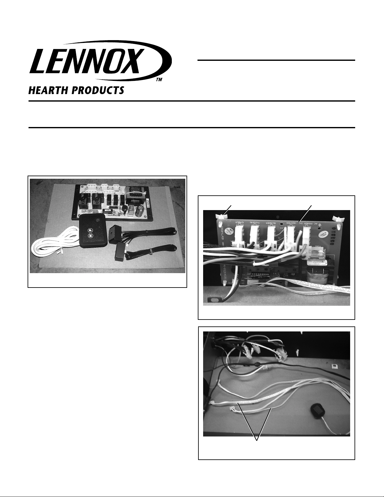
This Remote Control Replacement Kit is to be used to replace the
Reflections Electric Fireplace’s Remote Control. The kit components are
shown below.
P/N 750,251M
REV. A 01/2008
Step 5. Remove the grate.
Step 6. Remove the ember bed.
Step 7. Remove the fireplace floor.
Step 8. Remove the DVD player. Make sure to label the “Video Out” and
“Sound Out” cables when disconnected from the DVD player.
Plastic Holders Control Board
REFLECTIONS REMOTE CONTROL
REPLACEMENT KIT
(Kit Number H1454 And/Or H6977)
REPLACEMENT INSTRUCTIONS
Note: Depending on the type of control board in your fireplace, the
number of steps and components may vary. Following are the types of
control boards for identification:
If you have Kit Number H1094, it will be necessary to replace the board
and IR cables. In this case, complete all the Steps as outlined in these
instructions.
If you have Kit Numbers H1454 or H6977, it is not necessary to replace
the IR cables. In this case, skip Steps 11 through 21 and complete the
remaining process as outlined in these instructions.
Refer to the Reflections Fireplace Installation Instructions manual (No.
850,091M) for a visual aid on the following steps:
Step 1. Disconnect the electrical power to the fireplace.
Step 2. Remove the doors from the fireplace.
Step 3. Remove the reflective glass.
Step 4. Remove the logs.
Figure 1 (Kit Number H1094)
IR Cables
Figure 2
NOTE: DIAGRAMS & ILLUSTRATIONS NOT TO SCALE.
1
Page 2
Step 9. Locate the fireplace control board (Kit Number H1094) and
remove it, including the plastic holders (
Step 10. Disconnect the IR cables (ribbon type cables).
Figure 2
.
Refer to Figure 1
).
Refer to
Step 11. Locate the wire harness behind the right hand side frame.
Step 13. Pull the wire harness completely outside the cavity and remove
the flexible wire conduit to expose the wires completely (some early units
may have binding tape). If provided, save the flexible conduit to re-use.
Step 14. Leave the A/V cables in place. These cables are not being
replaced with the Remote Control Kit.
Refer to Figures 4 and 5
.
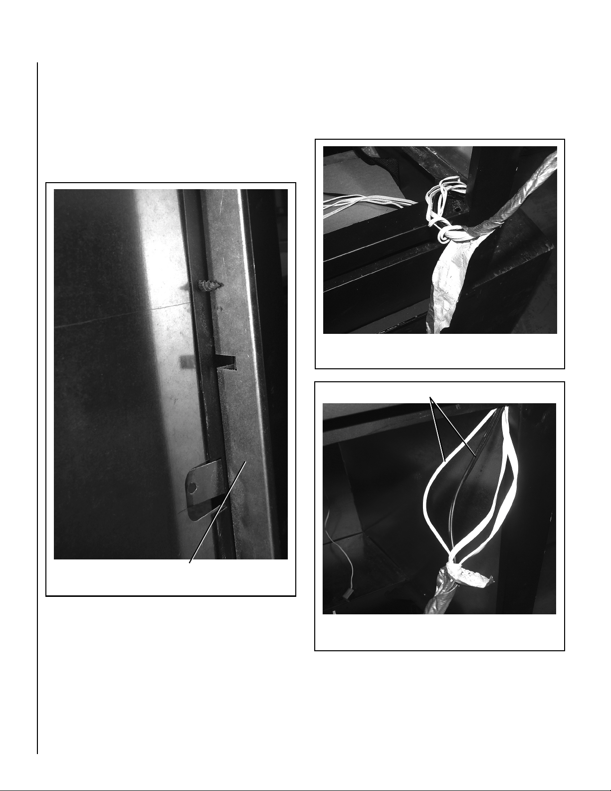
Step 12. Some early units may have a metal wire shield (
Figure 3
the shield upwards to align the slots to the screws and remove.
). Slide
Bottom Side View
Figure 4
A/V Cables
Wire Shield
Figure 3
Upper Side View
Figure 5
2
NOTE: DIAGRAMS & ILLUSTRATIONS NOT TO SCALE.
Page 3
Step 15. Locate the TV IR cable and cut about five (5) inches from the
end (
see Figure 6
).
Step 16. Twist the connector end of the new IR cable to the ends of the
old IR cable and wrap securely with duct tape.
Refer to Figure 7
.
Note: Free all cables from one another and pull them individually, as
they are replaced.
Cut Wire Ties If Provided
Pull To Replace
Figure 8
Step 17. Pull the TV IR cable until the new cable is out. Unwrap the tape
and discard the old cable (
see Figure 8
).
Locate The TV IR Cable
Figure 6
Figure 7
Twist And Tape
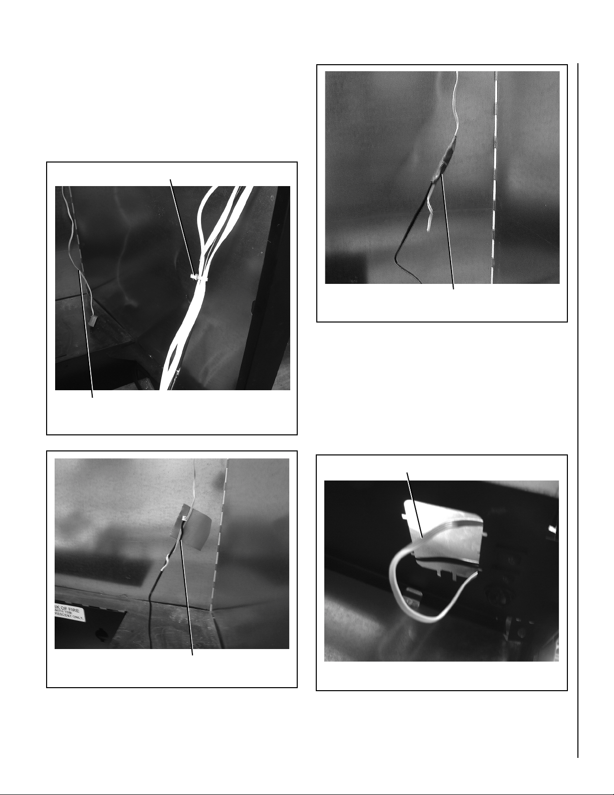
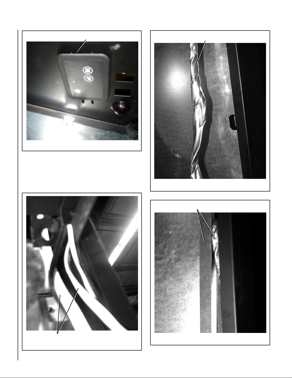
Step 18. Locate the Remote Control receiver through the rectangular
slot and pull the cables out and cut the ends free, enough to wrap the end
of the new receiver. Then fish them through the rectangular hole while
pulling, to route through the frame cavity (
see Figure 9
. )
Step 19. Push the Remote Control receiver into the rectangular slot
(
refer to Figure 10
Pull Remote Receiver Cables Out
).
Figure 9
NOTE: DIAGRAMS & ILLUSTRATIONS NOT TO SCALE.
3
Page 4
Push The Remote Receiver Into The Rectangular Slot
Figure 10
Step 20. Bundle the new cables and the A/V cables together and wrap
with masking tape, or rout them through the flexible conduit if provided.
See Figures 11 and 12
.
Bundle New Cables And A/V Cables Together With Tape
Step 21. Tack the wire harness into the side frame and replace the wire
harness shield, if provided (
see Figure 13
).
Figure 12
Tack Wire Harness Behind Side Frame
4
Figure 11
New Cables Routed
Figure 13
NOTE: DIAGRAMS & ILLUSTRATIONS NOT TO SCALE.
Page 5
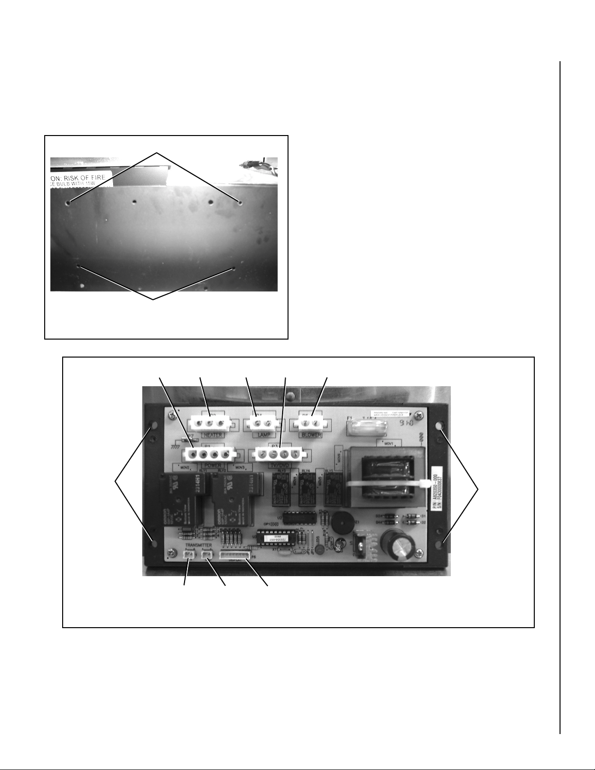
Step 22. Place the Control Board against the back wall and attach using
the top four (4) outermost holes with the screws and nuts provided.
Refer to Figures 14 and 15
.
Step 23. Plug all connectors into the new Control Board.
See Figure 15
.
Back Wall With Mounting Holes
Back Wall With Mounting Holes
Figure 14
Attach With
Screws Here
Figure 15
Power
Heater
TV
Mount The Control Board Using The Screws And Nuts Provided
Lamp
DVD
TV/DVD
Display
Blower
Attach With
Screws Here
NOTE: DIAGRAMS & ILLUSTRATIONS NOT TO SCALE.
5
Page 6
DVD INSTALLATION INSTRUCTIONS
Refer to the DVD Replacement Kit Installation Instructions manual (No.
750,250M) for additional aid on the following steps:
Step 1. Before installing the DVD player, connect the new DVD player
to an electrical outlet and insert the DVD disc into the drawer.
Step 2. Disconnect the DVD player and bring it into the fireplace cavity.
Step 3. Proceed to connect the A/V cables as labeled. Connect the
power cord.
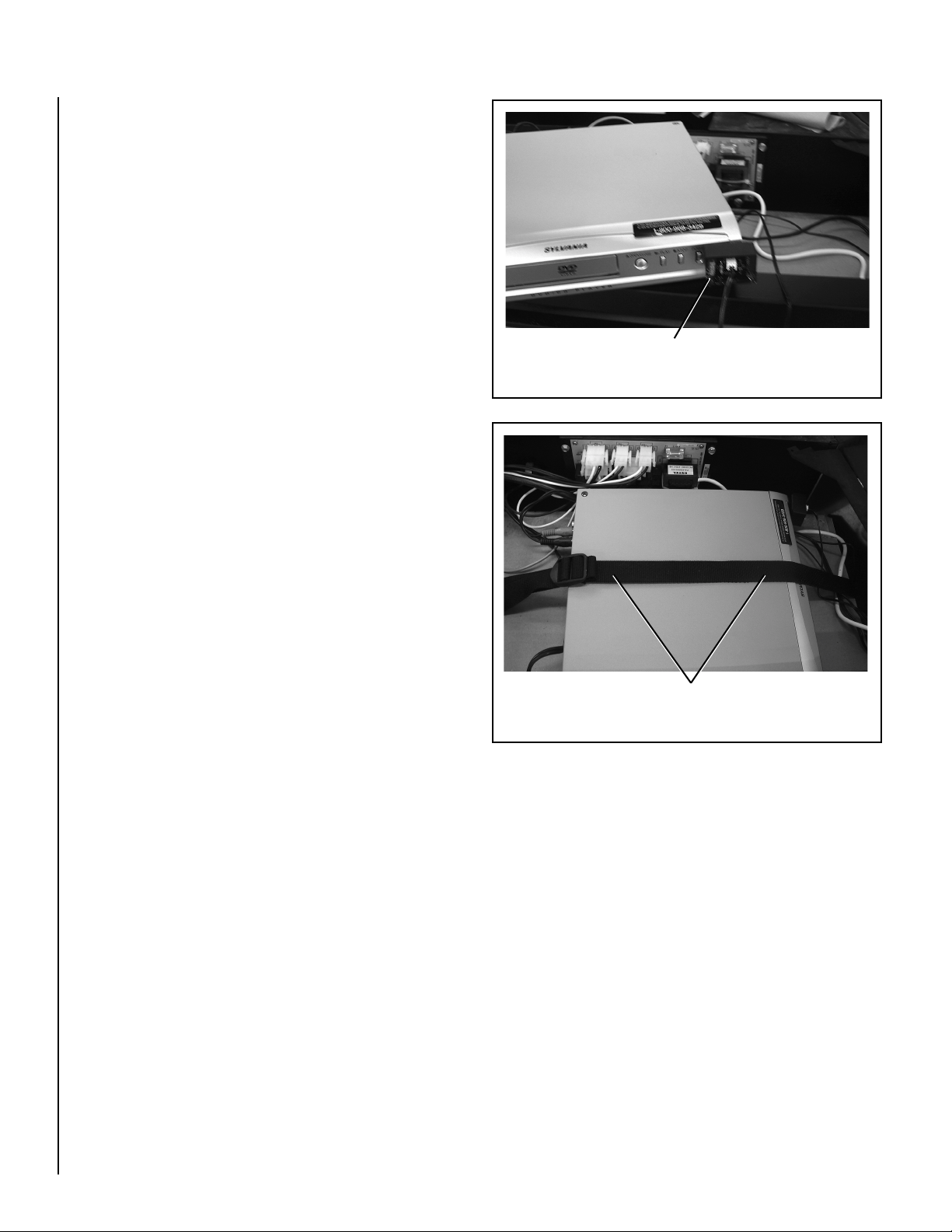
Step 4. Place a piece of Velcro on the DVD player eye and attach the IR
transmitter unit to it (
Step 5. With the controls facing to the right hand side, tilt the DVD player
sideways under the front frame, to insert it into position.
Step 6. Using the new remote control, test the fireplace for proper
operation.
see Figure 16
).
Attach A/V Cables And IR Transmitter Unit
Figure 16
Step 7. Strap the DVD player (
see Figure 17
).
Step 8. Re-assemble the fireplace parts in reverse order.
Strap The DVD Player
Figure 17
6
NOTE: DIAGRAMS & ILLUSTRATIONS NOT TO SCALE.
Page 7

NOTE: THIS PAGE INTENTIONALLY LEFT BLANK.
NOTE: DIAGRAMS & ILLUSTRATIONS NOT TO SCALE.
7
Page 8

The manufacturer reserves the right to make changes at any time, without notice, in design, materials, specifications, prices and also to discontinue colors, styles and products.
Consult your local distributor for fireplace code information.
Printed in U.S.A. © 2007 by LHP
P/N 750,251M REV. A 01/2008
8
NOTE: DIAGRAMS & ILLUSTRATIONS NOT TO SCALE.
1110 West Taft Avenue
Orange, CA 92865
 Loading...