

Lennox G24MCE2-45, G24MCE3-60, G24MCE3-75, G24MCE4-75, G24MCE4-100 Installation Instructions Manual
...Page 1
INSTALLATION
2000 Lennox Industries Inc.
Dallas, Texas
PRODUCT LITERATURE
RETAIN THESE INSTRUCTIONS
FOR FUTURE REFERENCE
INSTRUCTIONS
G24MCE Series
GAS-FIRED FURNACE
Direct Spark Ignition
503,956M
05/2000
Supersedes 11/99
Table of Contents
G24MCE Unit Dimensions 2. . . . . . . . . . . . . . . . . . . .
G24MCE GasĆFired Furnace 3. . . . . . . . . . . . . . . . . .
Shipping and Packing List 3. . . . . . . . . . . . . . . . . . . . .
Requirements 3. . . . . . . . . . . . . . . . . . . . . . . . . . . . . . .
General 3. . . . . . . . . . . . . . . . . . . . . . . . . . . . . . . . . . . .
Combustion, Dilution & Ventilation Air 4. . . . . . . . . .
Setting Equipment 6. . . . . . . . . . . . . . . . . . . . . . . . . . .
Duct System 9. . . . . . . . . . . . . . . . . . . . . . . . . . . . . . . .
Venting 9. . . . . . . . . . . . . . . . . . . . . . . . . . . . . . . . . . . . .
Vertical Flue Using Metal Flue Pipe 9. . . . . . . . . . .
Vertical Flue Using Lined Masonry Chimney 11. .
Horizontal Flue Using Metal Flue Pipe 12. . . . . . .
Gas Piping 13. . . . . . . . . . . . . . . . . . . . . . . . . . . . . . . . .
Electrical 15. . . . . . . . . . . . . . . . . . . . . . . . . . . . . . . . . .
Unit Start-up 18. . . . . . . . . . . . . . . . . . . . . . . . . . . . . . .
Unit Adjustments 19. . . . . . . . . . . . . . . . . . . . . . . . . . .
Service 20. . . . . . . . . . . . . . . . . . . . . . . . . . . . . . . . . . . .
Technical Data Table 22. . . . . . . . . . . . . . . . . . . . . . . .
Ignition Control Board Diagnostic Codes 23. . . . . . .
Troubleshooting 24. . . . . . . . . . . . . . . . . . . . . . . . . . . .
Repair Parts List 27. . . . . . . . . . . . . . . . . . . . . . . . . . . .
G24MCE Parts Arrangement 27. . . . . . . . . . . . . . . . .
G24MCE Start-up & Performance Check List 28. . .
Litho USA
If the information in this manual is not
followed exactly, a fire or explosion
may result causing property damage,
personal injury or loss of life.
Do not store or use petrol or other
flammable vapours and liquids in the
vicinity of this or any other appliance.
Installation and service must be perĆ
formed by a qualified installer, serĆ
vice agency or the gas supplier.
WARNING
WHAT TO DO IF YOU SMELL GAS:
Do not try to light any appliance.
Extinguish any open flames.
Do not touch any electrical switch; do not
use any telephone in your building.
Immediately call your gas supplier from a
neighbor's telephone. Follow the gas supĆ
plier's instructions.
If you cannot reach your gas supplier, call
the local fire brigade.
Page 1
Page 2
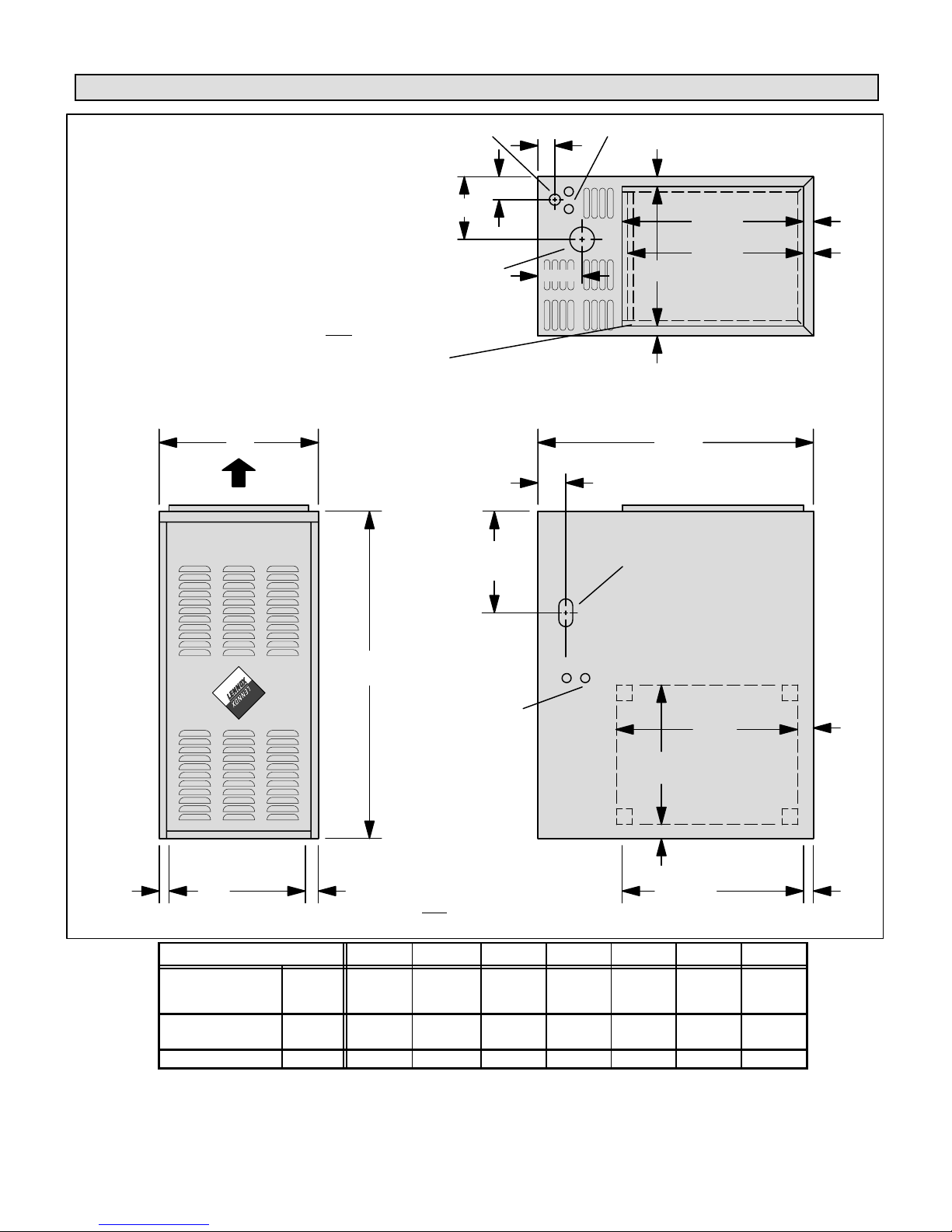
G24MCE Unit Dimensions - millimeters
G24MCE4/5Ć100
GAS PIPING
INLET
G24MCE Series
D
Unit shown in upflow position. Rotate 180° for
downflow applications and 90° clockwise or
counterclockwise for horizontal applications.
*NOTE - The supply air opening is equipped with a 19 mm scored
flange that may be bent 90_ for plenum connection.
The dimensions shown were taken after
The double scored flange at the front of the supply air
opening may be bent for a total opening dimension
(front to rear) of either 495 mm or 483 mm.
the flange was bent.
A
AIR FLOW
FLUE
OUTLET
F Left Side
G Right Side
ELECTRICAL INLETS
(Top & Bottom)
25
E
105
*C
25
*495
*483
SUPPLY
AIR
OPENING
25
25
TOP VIEW
752
51
GAS PIPING
INLET
(Both Sides)
B
ELECTRICAL
INLETS
(Both Sides)
381
**NOTEĊ The return air opening is
equipped with a 19 mm scored flange
Return Air
**C
Opening
FRONT VIEW
Model No. A B C D E F G
G24MCE2Ć45
G24MCE3Ć60/75
G24MCE4Ć75
G24MCE4/5Ć100
G24MCE4/5Ć120
G24MCE4/5Ć140 mm 591 991 540 248 108 329 180
mm 432 921 381 171 62 293 165
mm 521 991 470 213 108 331 203
that may be bent 90_ for plenum conĆ
2525 25
nection. The dimensions shown were
taken after
the flange was bent.
SIDE VIEW
495
RETURN AIR
KNOCKOUT
(Either Side)
19
495
Return Air
Opening
25
Page 2
Page 3
G24MCE GasĆFired Furnace
The G24MCE multi-position gas furnace is shipped ready
for installation in the upflow position. The unit can easily
be converted for installation in either downflow or horizonĆ
tal applications. The furnace is shipped with a bottom seal
panel in place for side return air in upflow applications.
Shipping and Packing List
Package 1 of 1 contains:
1 - Assembled unit
1 - Flue adapter (requires fieldĆinstallation)
1 - Upflow/horizontal filter rack
1 - Filter
The following additional items may be ordered separately,
if required:
1 - Additive base (downflow applications)
1 - Thermostat
1 - Hanging bracket kit
1 - External filter rack kit (downflow applications)
1 - LP Changeover kit
Check equipment for shipping damage. If you find any
damage, immediately contact the last carrier.
Requirements
Lennox G24MCE units carry CE marking and are certified
for installation in the following countries using the gas
categories shown:
II
: GB, IE, ES, PT and CH
2H3P
I
: DK and IT
2H
II
: NL
2L3P
II
: FR
2Er3P
I
and I
2ELL
*I
2E+(S)
* Units for installation in Belgium are set and sealed for use with
G20 reference gas and must not
Units must be adjusted or converted in accordance with
specific instructions provided by Lennox Industries prior
to installation or use in the other countries listed.
These appliances must only be installed, adjusted, conĆ
verted or serviced by properly qualified personnel. Failure
to comply with this requirements may result in a dangerĆ
ous situation.
The installation must comply with all relevant local and
national gas, electrical, building and fire regulations.
Proper ventilation is essential for safe operation and must
be provided as detailed in these instructions.
The flue system must be properly designed to comply with
any relevant regulations and the requirements set out in
these instructions.
Installation clearances must be provided around the apĆ
pliance and access provided for servicing requirements.
See figures 5, 7 and 9.
:DE
3P
:BE
be adjusted by installer.
Before installation, check that the local distribution condiĆ
tions, nature of gas and pressure and adjustment of the
appliance are compatible.
NOTE-For installation on combustible floors, appliance shall
not be installed directly on carpeting, tile, or combustible maĆ
terial such as wood flooring. Protection via a non-combusĆ
tible material must be provided.
The G24MCE unit must not be installed in a residential
or commercial garage.
Unit must be adjusted to obtain a temperature rise within the
range specified on appliance rating plate.
G24MCE unit must be installed so that electrical compoĆ
nents are protected from water.
When furnace is used in conjunction with cooling units, it
shall be installed on the upstream side of cooling units to
avoid condensation in the heating compartment.
When installed, furnace must be electrically earthed in
accordance with national regulations.
Electrical supply must be properly fused and should be
provided with means of isolating the unit from the supply.
When the furnace is installed so that supply ducts carry air
circulated by the furnace to areas outside of the space
containing the furnace, return air shall be handled by a
duct(s) sealed to the furnace casing and terminating outĆ
side of the space containing the furnace.
NOTE Ċ G24MCE series units must not be used as a
construction furnace" at any time during any phase of
construction. Very low return air temperatures, harmful
vapors and misplacement of the filters will damage the
unit and its efficiency.
The Lennox G24MCE furnace may be installed in alĆ
coves, cupboards, attics, basements, and utility rooms in
any of its approved installation positions.
The G24MCE unit must not be installed in a residential
or commercial garage.
The air furnace must not be installed in a room conĆ
taining a bath or shower. In addition, it is recomĆ
mended that the furnace should not be fitted in a bedĆ
room.
A compartment used to enclose the air furnace must be
designed and constructed specifically for this purpose.
An existing cupboard or compartment may be used proĆ
vided that it is modified for the purpose.
WARNING
The Fan door must be securely in place when the
fan and burners are operating. Gas fumes, which
could contain carbon monoxide, can be drawn into
living space resulting in personal injury or death.
General
These instructions are intended as a general guide and do
not supersede local codes in any way. Consult authorities
having jurisdiction before installation.
Page 3
Page 4
In addition to the requirements outlined previously, the folĆ
lowing general recommendations should be considered
when installing the Lennox G24MCE furnace.
The furnace should be placed as close to the center of the
air distribution system as possible. The furnace should
also be located close to the chimney or vent termination
point.
Do not install the furnace where draughts might blow diĆ
rectly into it. This could cause improper combustion and
unsafe operation.
Do not block furnace combustion air openings with clothĆ
ing, boxes, doors, etc. Combustion air is needed for propĆ
er combustion and safe unit operation.
When the furnace is installed in an attic or other insulated
space, keep insulation away from the furnace.
WARNING
Product contains glass fibre.
Surface tears due to rough handling during shipĆ
ping or installation should be repaired straight
away to avoid respiratory, skin and eye irritation.
Combustion, Dilution & Ventilation Air
In the past, there was no problem in bringing in sufficient outĆ
door air for combustion. Infiltration provided all the air that
was needed. In today's homes, tight construction practices
make it necessary to bring in air from outside for combustion.
Take into account that exhaust fans, appliance vents, chimĆ
neys, and fireplaces force additional air that could be used
for combustion out of the house. Unless outside air is brought
into the house for combustion, negative pressure (outside
pressure is greater than inside pressure) will build to the point
that a downdraft can occur in the furnace vent pipe or chimĆ
ney. As a result, combustion gases enter the living space
creating a potentially dangerous situation.
In the absence of local codes concerning air for combustion
and ventilation, this section outlines guidelines and recomĆ
mends procedures for installing G24MCE Furnaces in a
manner that ensures efficient and safe operation. Special
consideration must be given to combustion air needs as
well as requirements for exhaust vents and gas piping.
CAUTION
Do not install furnace in a corrosive or contaminated
atmosphere. Meet all combustion and ventilation air
requirements, as well as all local codes.
CAUTION
Insufficient combustion air can cause headaches,
nausea, dizziness or asphyxiation.
Combustion Air Requirements
All gasĆfired appliances require air for the combustion
process. If sufficient combustion air is not available, the
furnace or other appliance will operate inefficiently and
unsafely. Enough air must be provided to meet the needs
of all fuelĆburning appliances and appliances such as exĆ
haust fans which force air out of the house. When fireĆ
places, exhaust fans, or clothes dryers are used at the
same time as the furnace, much more air is required to enĆ
sure proper combustion and to prevent a downdraft. InĆ
sufficient air causes incomplete combustion which can reĆ
sult in carbon monoxide.
In addition to providing combustion air, fresh outdoor air
dilutes contaminants in the indoor air. These contamiĆ
nants may include bleaches, adhesives, detergents, solĆ
vents and other contaminants which can corrode furnace
components.
The requirements for providing air for combustion and
ventilation depend largely on whether the furnace is
installed in an unconfined or a confined space.
Unconfined Space
An unconfined space is an area such as a basement or
large equipment room with a volume greater than 4.85m
per 1 kW (50 ft3 per 1000 Btuh) of the combined input ratĆ
ing of all appliances installed in that space. This space
also includes adjacent rooms which are not separated by
a door. Though an area may appear to be unconfined, it
might be necessary to bring in outdoor air for combustion
if the structure does not provide enough air by infiltration.
If the furnace is located in a building of tight construction
with weather stripping and sealing around the windows
and doors, follow the procedures in the air from outside
section.
Confined Space
A confined space is an area with volume less than 4.85m
per 1 kW (50 ft3 per 1000 Btuh of the combined input rating
of all appliances installed in that space. This definition inĆ
cludes furnace cupboards or small equipment rooms.
When the furnace is installed so that supply ducts carry air
circulated by the furnace to areas outside the space containĆ
ing the furnace, the return air must be handled by ducts
which are sealed to the furnace casing and which terminate
outside the space containing the furnace. This is especially
important when the furnace is mounted on a platform in a
confined space such as a cupboard or small equipment
room. Even a small leak around the base of the unit at the
platform or at the return air duct connection can cause a poĆ
tentially dangerous negative pressure condition. Air for comĆ
bustion and ventilation can be brought into the confined
space either from inside the building or from outside.
3
3
Page 4
Page 5
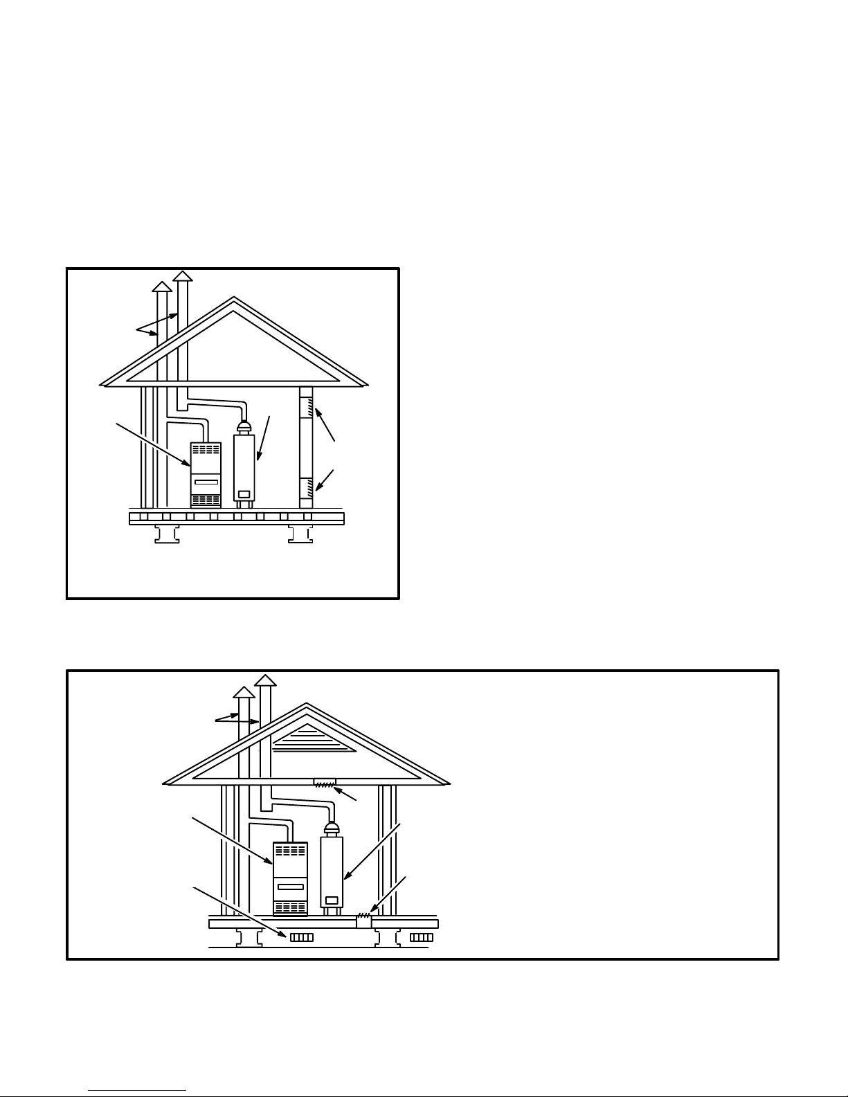
Air from Inside
If the confined space that houses the furnace adjoins a
space categorized as unconfined, air can be brought in by
providing two permanent openings between the two
spaces. Each opening must have a minimum free area of
2
22cm
per 1 kW (1 square inch per 1000 Btuh) of total input
rating of all gas-fired equipment in the confined space. Each
opening must be at least 646cm
2 (
100 square inches). One
opening shall be within 305mm (12 inches) of the top of the
enclosure and one opening within 305mm (12 inches) of the
bottom. See figure 1.
EQUIPMENT IN CONFINED SPACE
ALL AIR FROM INSIDE
CHIMNEY
OR GAS
VENT
G24MCE
FURNACE
WATER
FURĆ
NACE
OPENINGS
(To Adjacent
Room)
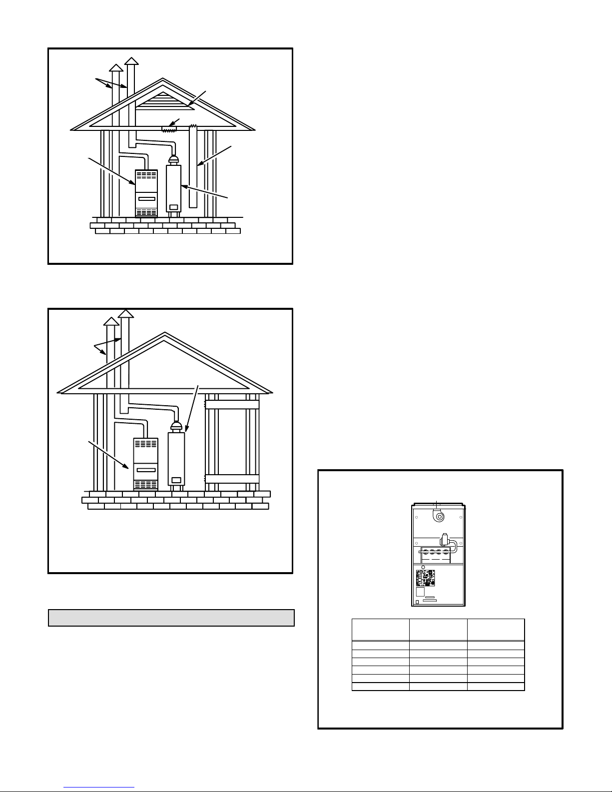
Air from Outside
If air from outside is brought in for combustion and ventilation,
the confined space must have two permanent openings.
One opening shall be within 305mm (12 inches) of the top
of the enclosure and one within 305mm (12 inches) of the
bottom. These openings must communicate directly or by
ducts with the outdoors or spaces (underfloor or attic) that
freely communicate with the outdoors or indirectly through
vertical ducts. Each opening shall have a minimum free area
of 5.5cm
2
per 1 kW (1 square inch per 4000 Btuh) of total
input rating of all equipment in the enclosure. See figures 2
and 3. When communicating with the outdoors through horiĆ
zontal ducts, each opening shall have a minimum free area
of 3cm
2
per 1 kW (1 square inch per 2000 Btuh) of total inĆ
put rating of all equipment in the enclosure. See figure 4.
When ducts are used, they shall be of the same cross-secĆ
tional area as the free area of the openings to which they
connect. The minimum dimension of rectangular air ducts
shall be no less than 75mm (3 inches). In calculating free
area, the blocking effect of louvers, grilles, or screens must
be considered. If the design and free area of protective covĆ
ering is not known for calculating the size opening required,
it may be assumed that wood louvers will have 20 to 25 perĆ
cent free area and metal louvers and grilles will have 60 to
75 percent free area. Louvers and grilles must be fixed in
the open position or interlocked with the equipment so that
they are opened automatically during equipment operation.
NOTE-Each opening shall have a free are a of at least 22cm
per 1 kW (1 square inch per 1,000 Btuh) of the total input rating
of all equipment in the enclosure, but not less than 646cm
(100 square inches).
FIGURE 1
CHIMNEY
OR GAS
VENT
VENTILATION LOUVERS
(Each end of attic)
G24MCE
FURNACE
VENTILATION
LOUVERS
(For unheated underfloor
space)
OUTLET
AIR
2
2
EQUIPMENT IN CONFINED SPACE
(Inlet Air from Underfloor Space and Outlet Air to Ventilated Attic)
WATER
FURĆ
NACE
INLET
AIR
NOTE-The inlet and outlet air openings shall each have a free
area of at least 5.5cm
of the total input rating of all equipment in the enclosure.
ALL AIR FROM OUTSIDE
2
per 1 kW (1 square inch per 4000 Btuh)
FIGURE 2
Page 5
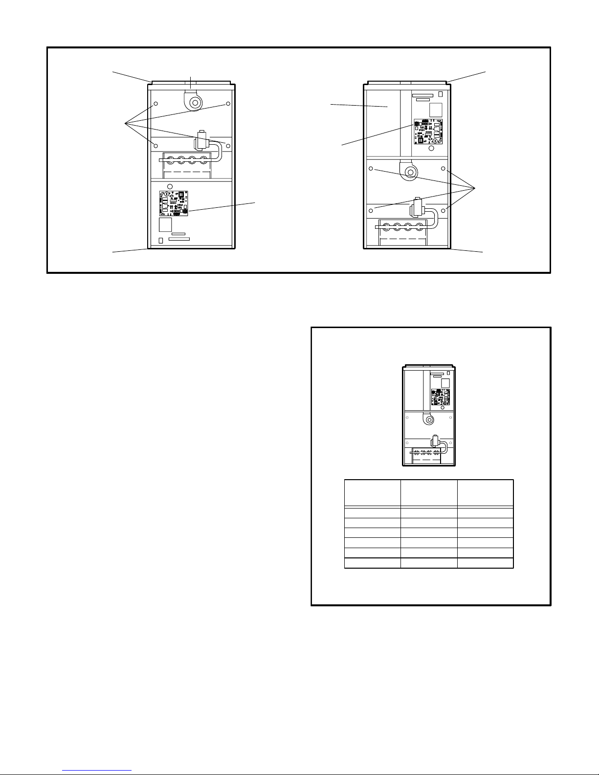
Page 6
EQUIPMENT IN CONFINED SPACE
CHIMNEY
OR GAS
VENT
G24MCE
FURNACE
NOTE-The inlet and outlet air openings shall each have a free area
of at least 5.5cm
input rating of all equipment in the enclosure.
2
per 1 kW (1 square inch per 4000 Btuh) of the total
ALL AIR FROM OUTSIDE
(All Air Through Ventilated Attic)
VENTILATION LOUVERS
(Each end of attic)
OUTLET
AIR
FURNACE
FIGURE 3
EQUIPMENT IN CONFINED SPACE
ALL AIR FROM OUTSIDE
CHIMNEY
OR GAS
VENT
WATER
FURNACE
OUTLET AIR
G24MCE
FURNACE
INLET AIR
INLET AIR
[Ends 305mm
(12") above botĆ
tom]
WATER
NOTE - 1/3 and 1/2 hp fan motors are equipped with eiĆ
ther four flexible mounting legs or three flexible legs and
one rigid leg. The rigid leg is equipped with a shipping bolt
and a flat white plastic washer (rather than the rubber
mounting grommet used with a flexible mounting leg).
This shipping bolt and flat washer must be removed beĆ
fore the furnace is put into operation. Once the shipping
bolt and washer are removed, the rigid leg will not touch
the fan housing.
UPFLOW APPLICATIONS
The Lennox G24MCE furnace is shipped in a standard
upflow position. Level the furnace using shims or leveling
bolts. Knockouts are provided in unit base to install fieldprovided leveling bolts. Allow for clearances to combusĆ
tible materials as indicated on the unit rating plate. MiniĆ
mum clearances for cupboard or alcove installations are
shown in figure 5.
In upflow applications, return air can be brought in
through the bottom or either side of the furnace. If a furĆ
nace with bottom return air is installed on a platform,
make an airtight seal between the bottom of the furnace
and the platform to ensure proper and safe operation.
Knockouts are provided on both sides of the furnace cabiĆ
net for installations with side return air. When side return
air is used, seal the bottom of the furnace using the panel
provided.
An upflow filter rack is provided. The adjustable rack can
be installed beneath the furnace (flush with cabinet
edges) for bottom return air applications or on the side of
the furnace for side return air.
NOTE - A sheet metal filter puller is provided along with
filter kit. In bottom return air applications, filter puller must
be installed between frame and filter to hold filter in place.
UPFLOW APPLICATION
INSTALLATION CLEARANCES
TOP
NOTE-Each air duct opening shall have a free area of at least 3cm2 per 1 kW
(1 square inch per 2000 Btuh) of the total input rating of all equipment in the
enclosure. If the equipment room is located against an outside wall and the
air openings communicate directly with the outdoors, each opening shall
have a free area of at least 5.5cm
the total input rating of all other equipment in the enclosure.
2
per 1 kW (1 square inch per 4000 Btuh) of
FIGURE 4
Setting Equipment
The Lennox G24MCE multi-position gas furnace can be
installed as shipped in upflow position or in horizontal
position with right-hand or left-hand discharge. The furĆ
nace can easily be converted for downflow applications.
Select unit location that will allow for required clearances
listed on the unit rating plate. Also consider gas supply
connections, electrical supply, vent connection and
installation and service clearances [610mm (24 in.)] at
unit front.
Page 6
LEFT
SIDE
BOTTOM
VENT
CONNECTOR
TYPE
TOP
*FRONT 51mm (2 in.)
BACK
SIDES
FLUE 25mm (1 in.)
BOTTOM **NC
*Front clearance in alcove installation must be a miniĆ
mum of 610mm (24 in.) for service access.
**On combustible floor with non-combustible protecĆ
tion. NC - Non-Combustible
SINGLE WALL
25mm (1 in.)
51mm (2 in.)
25mm (1 in.)
25mm (1 in.)
152mm (6 in.)
**NC
RIGHT
SIDE
TWIN WALL
25mm (1 in.)
25mm (1 in.)
25mm (1 in.)
FIGURE 5
Page 7
REMOVE
TOP CAP
REMOVE
FOUR
SCREWS
DISCONNECT
IGNITOR & SENSOR
LEADS
REMOVE
BOTTOM
SINGLE-WALLED VENT
PIPE FROM COMBUSTION
AIR FAN FLUE ADAPTER TO
FURNACE FLUE OUTLET
(Furnished by installer)
DISCONNECT
WIRE HARNESS AT
CONTROL BOARD
CONNECTOR
UPFLOW CONFIGURATION DOWNFLOW CONFIGURATION
FIGURE 6
DOWNFLOW APPLICATIONS
The Lennox G24MCE furnace is shipped in the upflow
configuration and must be converted for downflow instalĆ
lation. Refer to figure 6 and the following steps to convert
the unit for downflow installation:
1 - Place unit on its back and remove access panel.
2 - Disconnect wire harness in control area.
3 - Disconnect ignition lead and sensor wire located in
burner box. Use pliers to remove strain relief plugs
from holes on side of burner box.
4 - Remove four no. 10 screws securing cabinet bottom
to unit and remove bottom.
5 - Remove four no. 10 screws securing cabinet top cap to
cabinet. Remove top cap and replace with bottom.
6 - Remove four screws holding heat exchanger assemĆ
bly in place. Slide heat exchanger out through top of
cabinet.
UNIT CONVERSION FOR DOWNFLOW APPLICATION
7 - Rotate heat exchanger 180
o
and slide back into cabiĆ
net through top. Resecure using four screws.
8 - Install cabinet bottom using four no. 10 screws.
9 - Position strain relief grommets on ignition and flame
sensor wires. Insert wires and grommets through
holes on side of burner box. Reconnect wires to igniĆ
tor and flame sensor.
10- Reconnect wire harness plug.
11- Replace unit access panel.
In downflow applications, the unit can be installed in three difĆ
ferent ways: on non-combustible flooring, on combustible
floor using an additive base, or on a reverse-flow cooling cabĆ
inet. Do not drag unit across floor.
Allow clearances to combustible materials as outlined on
unit rating plate. Minimum clearances for cupboard or alĆ
cove installations are outlined in figure 7.
REINSTALL
TOP CAP ON
UNIT BOTTOM
RECONNECT WIRE
HARNESS AT
CONTROL BOARD
CONNECTOR
ROTATE HEAT
EXCHANGER
& REINSTALL
RECONNECT
IGNITOR & SENSOR
LEADS
REINSTALL
BOTTOM
ON UNIT
A separate downflow filter kit is available for use in downĆ
flow applications. Filter rack provided with unit is for use in
horizontal or upflow applications only.
DOWNFLOW APPLICATION
INSTALLATION CLEARANCES
TOP
LEFT
SIDE
BOTTOM
VENT
CONNECTOR
TYPE
TOP 25mm (1 in.)
*FRONT 51mm (2 in.)
BACK
SIDES
FLUE 152mm (6 in.) 25mm (1 in.)
BOTTOM NC** NC**
NC - Non-combustible floor
*Front clearance in alcove installation must be a min. of 610mm
(24 in.) for service access.
**With additive base on combustible floor.
SINGLE WALL TWIN WALL
25mm (1 in.)
51mm (2 in.)
RIGHT
SIDE
25mm (1 in.)25mm (1 in.)
25mm (1 in.)25mm (1 in.)
FIGURE 7
A-Installation on Non-Combustible Flooring
1 - Cut floor opening keeping in mind the clearances
listed on the unit rating plate. Also, keep in mind gas
supply and electrical supply, vent connections and
sufficient installation and service clearances. See
table 1 for correct floor opening size.
TOP
Page 7
Page 8
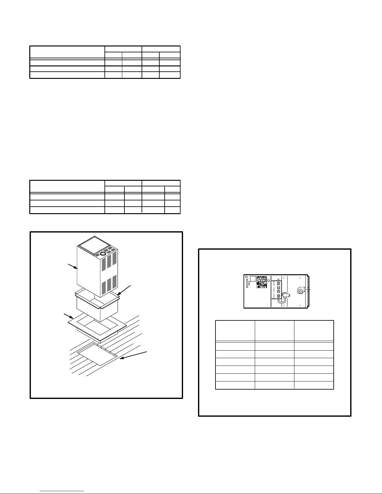
TABLE 1
NONCOMBUSTIBLE FLOOR OPENING
UNIT
G24MCE-45/60/75 502 388
G24MCE-100/120 502 47719-3/4 18-3/4
G24MCE-140 502 54619-3/4 21-1/2
NOTE-Floor opening dimensions listed are 6mm (1/4") larger
than unit openings.
Front to Rear Side to Side
inmm inmm
19-3/4 15-1/4
2 - Flange warm air plenum and lower into opening.
3 - Set unit over plenum.
4 - Check to see that an adequate seal is made.
B-Installation on Combustible Flooring
1 - When unit is installed on a combustible floor, an addiĆ
tive base (ordered separately) must be installed beĆ
tween the furnace and the floor. See table 2 for openĆ
ing size to cut in the floor.
TABLE 2
ADDITIVE BASE FLOOR OPENING
UNIT
G24MCE-45/60/75 556 440
G24MCE-100/120
G24MCE-140
NOTE-Floor opening dimensions listed are 1/4" (6mm) larger
than additive base openings.
G24MCE UNIT
Front to Rear Side to Side
in mm in mm
21-7/8 17-5/16
556 52821-7/8 20-3/4
556 59721-7/8 23-1/2
SUPPLY AIR
PLENUM
3 - Check glass fibre strips on additive base to make
sure they are properly glued and positioned.
4 - Lower supply air plenum into additive base until pleĆ
num flanges seal against glass fibre strips.
5 - Set unit on additive base so unit flanges drop into pleĆ
num. Refer to figure 8.
NOTE-Be careful not to damage glass fibre strips.
Check for tight seal.
C-Installation on Cooling Cabinet
1 - Refer to reverse flow coil installation instructions for
correctly sized opening in floor and installation of
cabinet.
2 - When cooling cabinet is in place, install furnace so
flanges drop inside cabinet opening.
3 - Seal cabinet and check for air leakage.
HORIZONTAL APPLICATIONS
The Lennox G24MCE furnace can be installed in horizonĆ
tal applications in either upflow or downflow configuration
(See figure 6). It is preferable to install the unit in the stanĆ
dard upflow configuration, if possible, because the vent
pipe will not interfere with service access for fan. The unit
cannot be installed on its back.
Filter rack is provided. Adjustable rack can be installed
flush with cabinet edges.
Allow for clearances to combustible materials as indicated
on the unit rating plate. Minimum clearances for cupboard
or alcove installations are shown in figure 9.
HORIZONTAL APPLICATION
INSTALLATION CLEARANCES
TOP
LEFT
SIDE
RIGHT
SIDE
ADDITIVE
BASE
1. Cut correct size floor opening
2. Set additive base into opening.
3. Set supply air plenum into additive base.
4. Set unit.
FIGURE 8
2 - After opening is cut, set the additive base into
opening.
PROPERLY
SIZED FLOOR
OPENING
Page 8
BOTTOM
VENT
CONNECTOR
TYPE
TOP 25mm (1 in.) 25mm (1 in.)
*FRONT 51mm (2 in.) 51mm (2 in.)
BACK
SIDES
FLUE 152mm (6 in.)
BOTTOM **NC **NC
*Front clearance in alcove installation must be a miniĆ
mum of 610mm (24 in.) for service access.
**On combustible floor with non-combustible protection.
NC - Non-Combustibles
SINGLE WALL TWIN WALL
25mm (1 in.) 25mm (1 in.)
51mm (2 in.) 51mm (2 in.)
25mm (1 in.)
FIGURE 9
Page 9
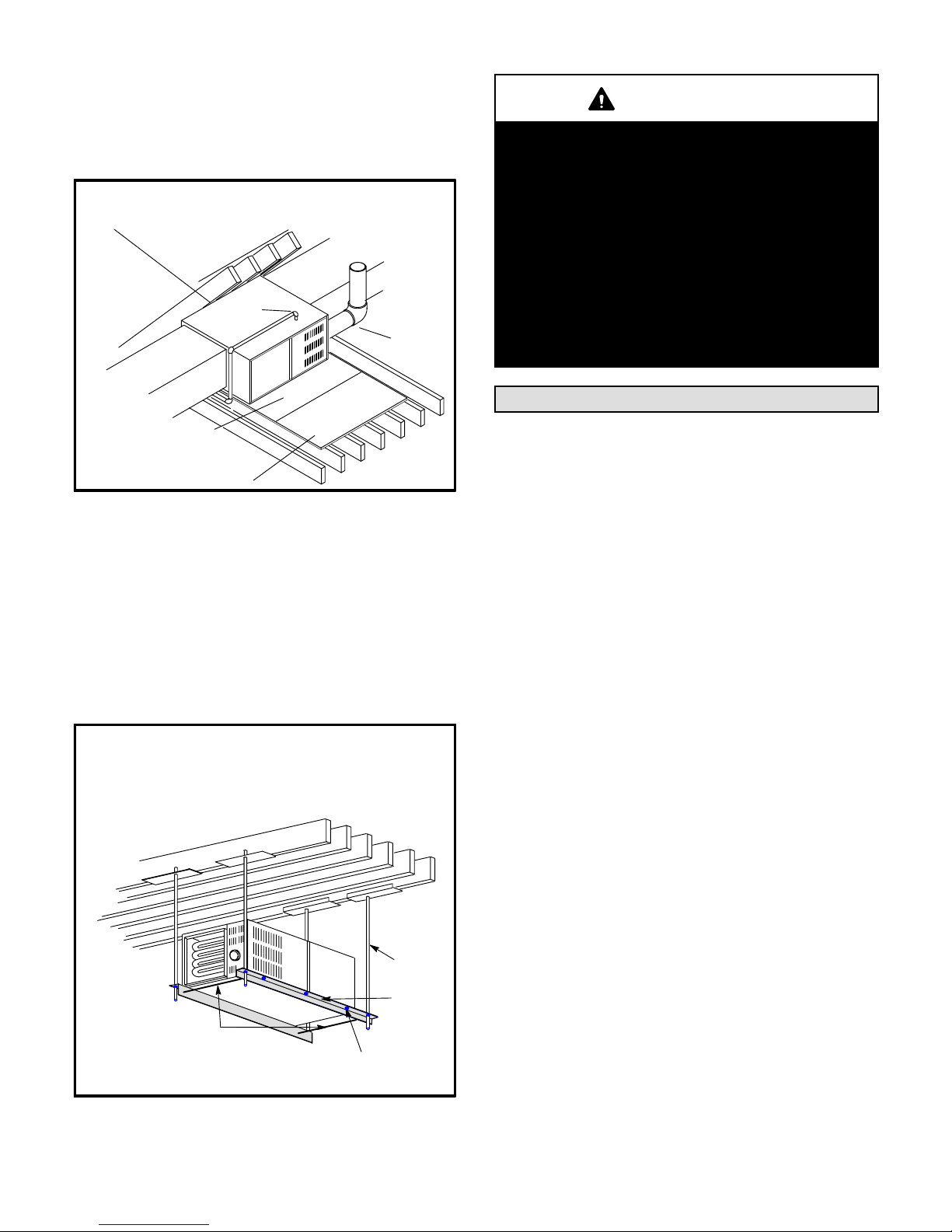
Furnaces may be installed in either an attic or a crawlspace.
See figure 10 for furnace installations on a platform.
NOTE - When the furnace is installed on a platform in a
crawlspace, it must be elevated enough to avoid water
damage and to allow the air conditioning coil to drain.
Horizontal Application
NOTE - Line contact is permiss ible. See the unit rating plate for clearan ces
Unit Installed on Platform
GAS
ENTRY
VENT
PIPE
WARNING
Improper installation of unit can result in personal
injury or death. Flue gases must never be allowed
to enter the return air system or the living space.
Sheet metal screws and sealing tape should be
used to seal ducting to the furnace. In platform
installations, return air must always be ducted to
the unit. A unit must never be installed so that it
draws return air from the furnace chamber, attic or
underfloor space. The furnace platform must be
level with no sagging, cracks or gaps.
Furnaces must always be isolated from other heatĆ
ing appliances to prevent fire, explosion, and carĆ
bon monoxide poisoning. Personal injury and/or
property damage could result..
Duct System
NON-COMBUSTIBLE
UNIT PLATFORM
NON-COMBUSTIBLE
WORKING PLATFORM
FIGURE 10
Anyone of the following methods may be used to suspend
the furnace from roof rafters or floor joists:
1 - Using Lennox hanging bracket kit catalog number
46J66 -
Install as indicated in the installation instructions
provided with the hanging bracket kit.
2 - Using angle iron with at least 1/4 in. diameter rods -
Install as shown in figure 11.
Note - Rods must not interfere with plenum or exĆ
haust piping; cooling coils and supply and return
air plenums must be supported separately.
Horizontal Application
Unit Suspended in Attic or Crawlspace
Using Angle Iron and Rods
Level unit - side to side and end to end.
Leave sufficient clearance between rod and unit to
remove access panels.
1/4 in. ROD
ANGLE
SUPPORT TIES -
INSTALL TO PREVENT
SPREADING
Secure the angle iron to the unit with sheetmetal screws:
maximum screw length - 3/4 in. and minimum screw size - # 10.
IRON
Use industryĆapproved standards to size and install the
supply and return air duct system. This will result in a quiet
and lowĆstatic system that has uniform air distribution.
SUPPLY AIR PLENUM
Furnaces installed without a cooling coil require the installaĆ
tion of a removable access panel in the supply air duct. The
access panel should be large enough to permit inspection
(either by smoke or reflected light) of the heat exchanger for
leaks after installation . The furnace access panel must alĆ
ways be in place when the furnace is operating and it must
not allow leaks into the supply air duct system.
RETURN AIR PLENUM
Return air must not be drawn from a room where
this furnace, or any other gas appliance (ie., a water
heater), is installed. When return air is drawn from a
room, a negative pressure is created in the room. If a
ga s appliance is oper ati ng in a ro om with negative presĆ
sure, the flue products can be pulled back down the vent
pipe and into the room. This reverse flow of the flue gas
may result in incomplete combustion and the formation
of carbon monoxide gas. This toxic gas might then be
distributed throughout the house by the furnace duct
system.
In upflow applications, return air can be brought in
through the bottom or either side of the furnace. If a furĆ
nace with bottom return air is installed on a platform,
make an airtight seal between the bottom of the furnace
and the platform to ensure proper and safe operation.
Use fiberglass sealing strips between the plenum and the
furnace cabinet to ensure a tight seal. If a filter is installed,
size the return air duct to fit the filter frame.
FIGURE 11
Page 9
Page 10

In downflow applications, use the following steps when
installing return air plenum:
1 - Flange bottom edge of plenum with a hemmed edge.
See figure 12.
2 - In all cases, secure the plenum to the top flanges of
the furnace using sheet metal screws. See figure 12.
PLENUM
SECURE
HEMMED EDGE
Venting
The G24MCE unit is not certified for common venting.
A flue adapter is supplied with the furnace. It must be fieldĆ
installed between the induced draught fan flue outlet and
the flue connector using one or two corrosion-resistant
sheet metal screws. Modification of or failure to install
the adapter will cause unsafe unit operation and will
void unit certification. The flue adapter does not require
insulation.
CABINET SIDE PANEL
FIGURE 12
3 - In cupboard installations, it may be necessary to
install sheet metal screws from the inside. If this is the
case, make plenum with a removable front to install
screws as shown in figure 13.
SECURE
FROM
INSIDE
CABINET SIDE PANEL
PLENUM
HEMMED EDGE
FIGURE 13
VERTICAL FLUE USING METAL FLUE PIPE
Note: See the regulations that are in force in the
country of installation for flue connector sizing.
FLUE CAP
STORM COLLAR
FLASHING
STRAIGHT PIPE
FIRST 152mm (6")
FLUE
ADAPTER
MIN. LENGTH - AS SHORT AS PRACTICAL
MAXIMUM LENGTH - SEE NOTE AT SIDE
(Double-walled, single-walled pipe)
CONNECTOR
VERTICAL FLUE USING METAL FLUE PIPE
The flue system should be of the same nominal diameter
as the adapter supplied with the unit and should be fitted
inside the adapter either directly or using a connector deĆ
signed for the flue system used. Where it is not possible to
use the same nominal diameter, a larger size may be
used with an appropriate conversion piece to suit the unit
adapter. A flue system of smaller nominal diameter than
the unit adapter must not be used.
NOTE - Use these instructions as a guide. They do not suĆ
persede local codes.
Size and install the G24MCE vertical flue per local codes
and regulations and these instructions.
See figure 14 for typical application of a vertical flue using
twin wall metal flue pipe.
3.05M (10 FT.)
MINIMUM
.61M (2 FT.)
1.5M (5 FT.)
POINT
MINIMUM
MINIMUM
FLUE
1M (3 FT.)
MINIMUM
DOUBLE
WALL
FLUE PIPE
HIGHEST FLUE
CONNECTOR
FIGURE 14
Page 10
Page 11

Recommendations and Requirements
When sizing and installing a vertical flue using metal flue
connectors and either metal flue pipe or a lined masonry
chimney, the following recommendations and requireĆ
ments should be considered in addition to those outlined
above:
1 - Accessories attached to the flue to reduce heat loss
and improve efficiency have not been tested for use
with this furnace.
2 - When the G24MCE furnace is replacing an existing
furnace, inspect the existing flue system for obstrucĆ
tions, corrosion and proper sizing.
3 - Make runs of single-walled or twin-walled metal pipe
used as flue connector easily accessible, so that it
can be inspected annually and cleaned and replaced
if necessary.
4 - See the regulations that are in force in the counĆ
try of installation for flue connector sizing.
5 - When the vent connector must be located in or pass
through a crawl space or other areas which may be
cold, that portion of the vent connector shall be a
listed twinĆwall flue pipe or a pipe of a material having
equivalent insulation qualities.
6 - Secure all joints with at least two corrosion-resistant
screws. Check all accessible joints for gas tightness
after installation.
WARNING
Failure to properly seal flue system could allow carĆ
bon monoxide leakage resulting in injury or death.
7 - Make flue connector horizontal runs as short as posĆ
sible with a minimum number of elbows. One 90° elĆ
bow is equivalent to 1.5m (5 ft.) of straight pipe. One
45° elbow is equivalent to .75m (2.5 ft.) of straight
pipe.
8 - Horizontal runs of flue connector must rise at least
20mm per meter (1/4 in. per ft.) away from the furĆ
nace.
9 - Horizontal run length must not represent more than 75
percent of the vertical rise of the flue system.
10 - Support horizontal runs of flue connector with straps or
hangers, so that there are no dips or sags.
11 - Support the flue connector at 1m (3 ft.) intervals and
at all elbows.
12 - If single wall flue is used, fasten the flue adapter to the
flue outlet of the furnace and the flue connector to the
flue adapter using one or two corrosion-resistant
sheet metal screws. If twin walled flue pipe is used,
fasten according to manufacturer's instructions
13 - Install first flue connector elbow a minimum of 6 in.
(152mm) from furnace flue outlet.
14 - Terminal location must not be within 600 mm (2 ft.) of
an openable window, air vent, or other ventilation
opening. Flue terminal must be located in accorĆ
dance with any national regulations applicable. A
flue guard must be fitted if required by the regulaĆ
tions.
15 - Fit a split flue socket immediately above the furnace
to facilitate servicing and maintenance.
16 - Flue pipes and fittings should be constructed of aluĆ
minium or stainless steel.
VERTICAL FLUE USING MASONRY CHIMNEY
The following additional requirements apply when a lined
masonry chimney is used to vent a G24MCE furnace:
See figure 15 for exterior chimney application.
Masonry chimneys that once served fireplaces cannot be
used for venting purposes unless the fireplace opening is
permanently sealed.
Tile-lined chimneys must be composed of a non-porous,
acid-resistant material. The internal diameter of the chimĆ
ney liner must not be less than the diameter of the furnace
flue adapter.
The G24MCE gas furnace must not be connected to a
chimney that is servicing a separate appliance which burns
solid fuel.
IMPORTANT
SINGLE appliance venting of a fanĆassisted furnace
into a tileĆlined masonry chimney (interior or outĆ
side wall) is PROHIBITED. The chimney must first
be lined with either twinĆwalled flue or an insulated
single wall flexible vent lining system, sized in acĆ
cordance with the the regulations in force in the
country of installation.
Page 11
Page 12

VENTING USING METAL-LINED
EXTERIOR MASONRY CHIMNEY
Note: See the regulations that are in force in the
country of installation for flue connector sizing.
MIN. LENGTH - AS SHORT AS PRACTICAL
MAXIMUM LENGTH - SEE NOTE AT SIDE
1.5m (5 FT.)
MINIMUM
EXTERIOR CHIMNEY WITH TWIN-WALLED LINER OR
INSULATED (FLEXIBLE) SINGLE-WALLED LINER.
SEALED
HIGHEST FLUE
CONNECTOR POINT
PERMANENTLY SEALED
FIREPLACE OPENING
FIGURE 15
Do not install a manual damper, barometric draught reguĆ
lator, or flue restrictor between the furnace and the chimĆ
ney. Remove any such existing devices.
If twin-wall flue is used inside a chimney, no other apĆ
pliance can be vented into the chimney. Outer wall of twinwall flue pipe must not be exposed to flue products.
If a flexible single-walled liner is used in a masonry chimĆ
ney, the liner must be insulated. Insulation for the flexible
vent pipe must be an encapsulated fiberglass sleeve recĆ
ommended by the flexible vent pipe manufacturer. See
figure 15.
If twin-wall flue or an insulated flexible vent pipe cannot be
used as liners, the chimney must be rebuilt to accommoĆ
date one of these methods or some alternate approved
method must be found to vent the appliance.
The space between the liner and the chimney wall
should NOT be insulated with puffed mica or any othĆ
er loose granular insulating material.
When inspection reveals that an existing chimney is not
safe for the intended purpose, it shall be rebuilt to conform
to nationally recognized standards. The chimney pasĆ
sageway must be checked periodically to ensure that it is
clear and free of obstructions.
HORIZONTAL FLUE USING METAL FLUE PIPE
These instructions should be used as a guide and do not
supersede local codes in any way. Size and install the
G24MCE horizontal flue according to the national and loĆ
cal codes and regulations which are in effect in the counĆ
try of installation.
The following are specific requirements for installation of
the G24MCE furnace:
1 - Install first flue connector elbow a minimum of
152mm (6 in.) from the furnace flue outlet.
2 - If the flue is sloped upward as it is routed away from
the furnace, the furnace must be protected from the
condensate produced in the flue.
3 - The flue system must be sealed (all joints must be
sealed), as positive pressure can occur in the flue.
4 - A 152mm (6 in.) clearance must be maintained to all
combustibles when single-walled flue pipe is used. A
25mm (1 in.) clearance to all combustibles must be
maintained when twin-walled flue pipe is used.
5 - If single-walled flue is used, fasten the flue adapter
to the flue outlet of the furnace and the flue connector
to the flue adapter using one or two corrosion-resisĆ
tant sheet metal screws. If twin-walled flue pipe is
used, fasten to the adapter according to manufacturĆ
er's instructions.
6 - Support flue as required by the regulations in force.
7 - See table 3 for flue diameter, equivalent lengths and
termination allowed.
8 - The tee termination shown in figures 16 and 17 is the
only acceptable termination.
MODEL SIZE
45
60/75/100/120/140
*One 905 elbow equals 1.5 m (5 ft.) of straight pipe. One 455 elbow equals 0.75 m (2.5 ft.) of straight pipe.
UNIT ORIENTATION
HORIZONTAL
UPFLOW / DOWNFLOW
HORIZONTAL 102 (4) 3 (10) 9.2 (30)
UPFLOW / DOWNFLOW 102 (4) 3 (10) 13.7 (45)
TABLE 3
HORIZONTAL FLUE PIPE SIZING
MINIMUM FLUE PIPE
DIAMETER mm (in.)
102 (4) 3 (10) 9.2 (30) 1
MINIMUM FLUE
EQUIVALENT
LENGTH* m (ft.)
Page 12
MAXIMUM FLUE
EQUIVALENT
LENGTH* m (ft.)
TERMINATION
TEE
1
Page 13

9 - The flue termination must be located in accordance
with any national regulations applicable. The termiĆ
nal must be designed such that it will not allow entry
of a 16mm (.6 in.) ball when applied with a 5N force.
A terminal guard must be applied where required by
national regulations.
HORIZONTAL TERMINATION DETAIL
WALL THIMBLE
(inside wall)
OUTER
OVERLAPPING
SHIELD
FLUE PIPE
INNER
SHIELD
INSIDE
WALL
WALL THIMBLE
(outside wall)
SHIELD
COUPLING
203mm
(8 in.) MIN.
PROTECTIVE SCREEN
INNER
(Both ends)
FIGURE 16
HORIZONTAL TERMINATION DETAIL
HIGH WINTER SNOW LEVELS
WALL THIMBLE
FOR COMBUSTIBLE
MATERIALS CLEARANCES
306mm (12 in.) MIN.
ABOVE NORMALLY
EXPECTED SNOW
ACCUMULATION
SEAL
2 - Meters - A gas meter is connected to the service pipe
by the gas supply authorities. An existing meter
should be checked by the gas supply authorities to
ensure that the meter is adequate to deal with the
rate of gas supply required.
3 - Pipework from the meter to the air furnace must be
of adequate size. Do not use pipes of a smaller size
than the inlet gas connection on the furnace. The
complete installation must be tested for soundness
as described in the codes in force.
4 - This unit is shipped standard for left or right side
installation of gas piping (or top entry in horizontal
applications). Connect the gas supply to the piping
assembly.
5 - When connecting gas supply, factors such as
length of run, number of fittings and furnace rating
must be considered to avoid excessive pressure
dr op. Table 4 and 5 list recom mended pipe sizes for
typical applications.
6 - The gas piping must not run in or through air ducts,
clothes chutes, chimneys or gas vents, dumb waiters
or elevator shafts.
7 - In some localities, it may be necessary to take preĆ
cautions against condensation in gas pipes. Where
condensation in pipes is considered likely to occur,
or if such precautions are required by national reguĆ
lations, the following steps should be taken to preĆ
vent condensation from entering the unit.
The piping should be sloped 1/4 inch per 15 feet upward
toward the meter from the furnace. The piping must be
supported at proper intervals (every 8 to 10 feet) using
suitable hangers or straps. A drip leg should be installed
in vertical pipe runs to the unit.
8 - A manual main shut-off valve and union (furnished
by installer) should be installed external to the unit.
Union must be of the ground joint type. See figure 18.
GROUND
LEVEL
FIGURE 17
Gas Piping
GAS SUPPLY
1 - Service pipes - The gas supply authorities should be
consulted at the installation planning stage in order to
establish the availability of an adequate supply of gas.
IMPORTANT
Compounds used on threaded joints of gas piping
must be resistant to the actions of liquified petroĆ
leum gases.
NOTE - Install an 1/8" RC plugged tap in the field piping upĆ
stream of the gas supply connection to the unit. Tap must
be accessible for test gauge connection. See figure 18.
NOTE - In case emergency shutoff is required, shut off main
manual gas valve and disconnect electrical power to unit.
These devices should be properly labeled by the installer.
Page 13
Page 14

TABLE 4 - GAS PIPE CAPACITY (FT3/HR)
Nominal
Iron Pipe Size
inches
1/4 .364 43 29 24 20 18 16 15 14 13 12
3/8 .493 95 65 52 45 40 36 33 31 29 27
1/2 .622 175 120 97 82 73 66 61 57 53 50
3/4 .824 360 250 200 170 151 138 125 118 110 103
1 1.049 680 465 375 320 285 260 240 220 205 195
1-1/4 1.380 1,400 950 770 660 580 530 490 460 430 400
1-1/2 1.610 2,100 460 1,180 990 900 810 750 690 650 620
2 2.067 3,950 2,750 2,200 1,900 1,680 1,520 1,400 1,300 1,220 1,150
2-1/2 2.469 6,300 4,350 3,520 3,000 2,650 2,400 2,250 2,050 1,950 1,850
3 3.068 11,000 7,700 6,250 5,300 4,750 4,300 3,900 3,700 3,450 3,250
4 4.026 23,000 15,800 12,800 10,900 9,700 8,800 8,100 7,500 7,200 6,700
Internal
Diameter
inches
10 20 30 40 50 60 70 80 90 100
NOTE-Capacity given in cubic feet of gas per hour and based on 0.60 specific gravity gas.
Length of Pipe - feet
TABLE 5 - GAS PIPE CAPACITY (M3/HR)
Nominal
Iron Pipe Size
inches
1/2 .622
3/4 .824
1 1.049
1-1/4 1.380
1-1/2 1.610
2 2.067
2-1/2 2.469
3 3.068
4 4.026
Internal
Diameter
inches
3 6 9 12 15 18 21 24 27 30
4.29 3.40 2.74 2.32 2.06 1.87 1.72 1.61 1.50 1.41
10.20 7.08 5.66 4.81 4.27 3.91 3.54 3.34 3.11 2.91
19.27 13.17 10.62 9.06 8.07 7.36 6.80 6.23 5.80 5.52
39.67 26.92 21.82 18.70 16.43 15.02 13.88 13.03 12.18 11.33
59.51 41.37 33.43 28.05 25.50 22.95 21.25 19.55
111.93 79.93 62.34 53.84 47.60 43.07 39.67 36.84 34.57 32.58
178.53 123.27 99.75 85.01 75.09 68.01 63.76 58.09 55.26 52.62
311.72 218.20 117.11 150.19 134.60 121.85 110.52 104.85 97.76 92.10
651.78 447.74 308.89 274.88 249.37 249.37 229.54 212.53 204.03 189.86
NOTE-Capacity given in cubic metres of gas per hour and based on 0.60 specific gravity gas.
Length of Pipe - metres
18.42
17.56
LEFT SIDE PIPING (STANDARD)
MANUAL
MAIN SHUT-OFF VALVE
(With 1/8" RC
Plugged Tap Shown)
GROUND
JOINT
UNION
DRIP LEG
(optional)
AUTOMATIC
GAS VALVE
AND INSTALLED
FIGURE 18
SOUNDNESS CHECK
After gas piping is completed, carefully check all piping
connections (factory- and field-installed) for gas leaks.
Use a leak detecting solution or other preferred means.
NOTE - In case emergency shutdown is required, shut
down main manual gas valve and disconnect electrical
power to unit. These devices should be properly labeled
by the installer.
MAIN SHUT-OFF
RIGHT SIDE PIPING
(ALTERNATE)
FIELD
PROVIDED
AUTOMATIC
GAS VALVE
CAUTION
Some soaps used for leak detection are corrosive
to certain metals. Carefully rinse piping thoroughly
after leak test has been completed. Do not use
matches, candles, flame or other sources of igniĆ
tion to check for gas leaks.
The furnace must be isolated from the gas supply system
by closing its individual manual shut-off valve during any
pressure testing of the gas supply system at pressures
equal to or less than 20 in. w.c. (50 mBAR).
MANUAL
VALV E
(With 1/8" RC
Plugged Tap
Shown)
GROUND
JOINT
UNION
DRIP LEG
(optional)
Page 14
Page 15

IMPORTANT
At pressures greater than 20 in. w.c. (50 mBAR), gas
valve must be disconnected and isolated. See figĆ
ure 19. Gas valves can be damaged if subjected to
more than 20 in. w.c. (50 mBAR).
MANUAL MAIN
SHUT-OFF VALVE
WILL NOT HOLD
NORMAL TEST
PRESSURE
CAP
ISOLATE
GAS VALVE
furĆ
nace
FIGURE 19
Electrical
CAUTION
Electrostatic discharge can affect electronic comĆ
ponents. Take precautions during furnace installaĆ
tion and service to protect the furnace's electronic
controls. Precautions will help to avoid control exĆ
posure to electrostatic discharge by putting the
furnace, the control and the technician at the same
electrostatic potential. Neutralize electrostatic
charge by touching hand and all tools on an unĆ
painted unit surface, such as the gas valve or blowĆ
er deck, before performing any service procedure.
These units operate on 240 volt, single phase, 50 hertz
electrical power. Refer to figure 20 for field wiring and figĆ
ure 22 for schematic wiring diagram and troubleshooting.
1 - Select circuit protection and wire size according to
requirements listed on unit rating plate.
2 - Knockouts are provided on both sides of the furnace
cabinet to facilitate wiring.
3 - Install room thermostat according to instructions proĆ
vided with thermostat.
4 - Install a separate disconnect switch (protected by eiĆ
ther fuse or circuit breaker) near the unit so power
can be turned off for servicing.
5 - Before connecting thermostat or power wiring, check
to make sure wires will be long enough to facilitate
servicing at a later date. Remove blower access panĆ
el and swing panel to check wire length for access.
6 - Complete wiring connections to equipment using wirĆ
ing diagrams provided with unit and in field wiring diaĆ
grams shown in figures 20. Use 18 gauge wire or largĆ
er for thermostat connections.
7 - Electrically earth unit according to national regulaĆ
tions.
8 - Three 240 volt accessory terminals are provided on
the control board. Two are energized with the indoor
blower and one is energized with the combustion air
blower. Any accessory rated up to one amp can be
connected to the accessory terminals with the neutral
leg of the circuit being connected to the 240 volt neuĆ
tral wires.
9 - This unit is equipped with an integrated control board
that controls blower operation, fan off timings and igniĆ
tion. The board includes a terminal strip for thermostat
connections and two diagnostic LEDs. See figure 21
for control board configuration. Diagnostic codes are
given in a chart at the back of this manual.
The red diagnostic button can be used to view the
last failure code.
10- Refer to blower speed chart on wiring diagrams for
factoryĆset cooling, heating and continuous fan
speeds.
Systems using a cooling thermostat subbase may
operate the blower continuously (factory set at low
speed) through the thermostat FAN ON" switch.
Systems which do not include a cooling subbase reĆ
quire a toggle switch which must be wired between
terminals R" and G" on the thermostat connection
terminal strip.
The blower motor will operate at the designated
speed during cooling or heating demand; however,
when demand is satisfied, blower speed will revert to
selected continuous speed.
TYPICAL G24MCE FIELD WIRING DIAGRAM
HEAT ONLY
THERMOSTAT
HEAT/COOL
THERMOSTAT
W
TO COMPRESSOR
CONTACTOR
RW
RGY
HIGHLIMIT
PRESSURE
SWITCH
CONTROL
BOARD
R
G
W
Y
C
TRANSFORMER
CAPILLARY
TUBE LIMIT
GAS
VALV E
BLACK
WHITE
DOOR
INTERLOCK
FUSED OR
CIRCUIT
BREAKER
ISOLATOR
(Furnished by
installer)
240V, 1PH, 50HZ
L1 N
FIGURE 20
Page 15
Page 16

HEATING SPEED
TAP TERMINAL
EGC-3ACE INTEGRATED CONTROL BOARD
CONTINUOUS FAN
TERMINAL
COOLING SPEED
TAP TERMINAL
ACCESSORY
TERMINALS
HEATING
ACCESSORY
TERMINAL
TERMINALS
L1
NEUTRAL
L2
DIAGNOSTIC
LEDS
BLOWER TIME
ADJUSTMENT
JUMPER
GND
DIAGNOSTIC CODE
ERASE JUMPER
(Remove power to control
and short pins for 10 secĆ
onds to erase previous
code.)
RED DIAGNOSTIC BUTTON
(Depress button and hold for
display of last failure code.)
THERMOSTAT
TERMINAL STRIP
FIGURE 21
Page 16
Page 17

G24MCE SCHEMATIC WIRING DIAGRAM
(240V, 1PH, 50HZ)
03/99
FIGURE 22
Page 17
Page 18

Unit Start-Up
FOR YOUR SAFETY READ BEFORE OPERATING
5 - Wait five (5) minutes to clear out any gas. If you then
smell gas, STOP! Immediately call your gas supplier
from a neighbor's phone. Follow the gas supplier's
instructions. If you do not smell gas go to next step.
WARNING
Do not use this furnace if any part has been underĆ
water. Immediately call a qualified service techniĆ
cian to inspect the furnace and to replace any part
of the control system and any gas control which
has been under water.
WARNING
If overheating occurs or if gas supply fails to shut
off, shut off the manual gas valve to the appliance
before shutting off electrical supply.
CAUTION
Before attempting to perform any service or mainteĆ
nance, turn the electrical power to unit OFF at isolaĆ
tor switch.
BEFORE LIGHTING smell all around the appliance area
for gas. Be sure to smell next to the floor because some
gas is heavier than air and will settle on the floor.
Use only your hand to turn the main manual gas cock. Never
use tools. If the knob will not turn by hand, do not try to repair
it, call a qualified service technician. Force or attempted reĆ
pair may result in a fire or explosion.
PLACING FURNACE INTO OPERATION
G24MCE units are equipped with an automatic direct
spark ignition system. Do not
burners on these Furnaces. Each time the thermostat
calls for heat, the burners will automatically light.
attempt to manually light
WARNING
If you do not follow these instructions exactly, a fire
or explosion may result causing property damage,
personal injury or death.
GAS VALVE OPERATION (Figure 23)
1 - STOP! Read the safety information at the beginning
of this section.
2 - Set the thermostat to the lowest setting.
3 - Turn off all electrical power to the unit.
4 - This furnace is equipped with an ignition device
which automatically lights the burners. Do not try to
light the burners by hand.
S.I.T. GAS VALVE
MANIFOLD
PRESSURE
OUTLET
MANIFOLD
PRESSURE
ADJUSTMENT
SCREW
FIGURE 23
6- Turn on all electrical power to the unit.
7- Set the thermostat to desired setting.
8- If the appliance will not operate, follow the instrucĆ
tions Turning Off Gas To Unit" and call your service
technician or gas supplier.
NOTE-When unit is initially started, steps 1 through 7
may need to be repeated to purge air from gas line.
TURNING OFF GAS TO UNIT
1 - Set the thermostat to lowest setting.
2 - Turn off all electrical power to the unit if service is to
be performed.
Heating Sequence of Operation
1 - When thermostat calls for heat, combustion air blowĆ
er starts after a 5 second delay.
2 - Combustion air pressure switch proves blower opĆ
eration, then allows power to ignition control. Switch
is factory set and requires no adjustment.
3 - After 15-second prepurge, spark ignitor energizes
and gas valve solenoid valves open.
4 - Spark ignites gas, ignition sensor proves the flame
and combustion process continues.
5 - If flame is not detected after first ignition trial, igniĆ
tion control will repeat steps 3 and 4 four more
times before locking out. To reĆestablish ignition
attempts after lockout, proceed as follows:
a - Turn OFF the power to the furnace.
b - Move the thermostat control from the HEAT" to
the OFF" position.
c - Turn ON the power to the furnace.
d - Move the thermostat control from the OFF" to
HEAT" position.
Page 18
Page 19

Unit Adjustments
HIGH LIMIT AND CAPILLARY TUBE LIMIT
The high limit and manuallyĆreset capillary tube limit are
both located on the heating compartment vestibule panel.
Both limits are factory set and do not require field adjustĆ
ment.
When there is inadequate supply air (a high supply air
temperature), the high limit shuts off the gas supply to
the burners, turns the combustion air blower OFF, and
keeps the air circulating blower ON until the limit resets
itself. While the limit is open, the control board displays
DIAG.1 - FLASHING; DIAG.2 Ć ON. If the limit trips 5
times in succession, a 60 minute Watchguard" occurs.
After 60 minutes, the control board automatically resets
itself. (The control board can also be reset by switching
the thermostat from HEAT to OFF and then back to
HEAT again.)
When there is inadequate supply air (a high supply air
temperature), the manuallyĆreset capillary tube limit
shuts off the gas supply to the burners and turns both the
combustion air blower and the air circulating blower OFF.
(The air circulating blower turns off only after its preset
delayĆoff time expires). While the limit is open, the control
board then displays DIAG.1 - ON; DIAG.2 Ć FLASHING.
To reset the limit, allow the furnace to cool, and then push
the switch on the limit's face inward.
If either limit trips, check for clogged filters or blocked supĆ
ply/return air grilles.
COMBUSTION AIR PRESSURE SWITCH
The combustion air pressure switch is located on the
heating compartment vestibule panel. This switch checks
for proper combustion air fan operation before allowing
ignition trial. The switch is factoryĆset and requires no field
adjustment.
FAN CONTROL
The fan control is part of the control board located on the
heating compartment vestibule panel. The preset fan on
delay time of 45 seconds is not adjustable. The fan off
delay time is factory adjusted at 120 seconds and can be
adjusted by moving the jumper on the integrated control
board. See figure 24 for settings.
TIMING
JUMPER
120
90 60
FAN-OFF TIME ADJUSTMENT
To adjust fan-off timings:
Remove jumper and select one of the
other pin combinations to achieve the
180
desired time.
TIMING PINS
(seconds)
FIGURE 24
GAS FLOW
To check for proper gas flow to combustion chamber, deterĆ
mine heat (kW) input from the unit rating plate. Divide this
input rating (MJ/hr) by the calorific value per unit volume
(MJ/m3) of the gas being used. Result is the volume of gas
required per hour. Determine the flow of gas through gas
meter for two minutes and multiply by 30 to get the hourly
flow of gas.
GAS PRESSURE
1 - Check the gas line pressure with unit firing at maximum
rate. See technical data table on page 22 for minimum
and maximum allowable pressure.
2 - After line pressure has been checked and adĆ
justed, check manifold pressure. Manifold pressurĆ
es are given in technical data table on page 22. See
figure 23 for gas pressure adjustment screw location.
TEMPERATURE RISE
Check the temperature rise and, if necessary, adjust fan
speed to maintain the temperature rise within range
shown on the unit rating plate.
If outdoor air is added to the recirculating room air, the
mixed air temperature at the heat exchanger should not
be lower than 15.5°C for extended periods of time.
THERMOSTAT HEAT ANTICIPATION
Set thermostat heat anticipation to:
0.80 amps S.I.T. gas valve
ELECTRICAL
1 - Check all wiring for loose connections.
2 - Check for correct voltage at the furnace (furnace opĆ
erating).
3 - Check amp-draw on fan motor.
Motor Nameplate__________Actual__________
FAN SPEEDS
Note - CFM readings are taken external to unit with a dry
evaporator coil and without accessories.
1 - Turn off electrical power to furnace.
2 - Remove unit access panel.
3 - Disconnect existing speed tap at control board
speed terminal.
NOTE - TERMINATION OF ANY UNUSED MOTOR
LEADS MUST BE INSULATED.
4 - Refer to fan speed selection chart on unit wiring diaĆ
gram for desired heating or cooling speed.
5 - Connect selected speed tap at control board speed
terminal.
6 - Resecure blower access panel.
7 - Turn on electrical power to furnace.
FLUE AND CHIMNEY
1 - Check flue pipe, chimney and all connections for
tightness and to make sure there is no blockage.
2 - Check unit for proper draught.
3 - Is pressure switch closed? Obstructed flue will cause
unit to shut off at pressure switch. Check flue and
outlet for blockages.
Page 19
Page 20

BURNER FLAME ADJUSTMENT
The G24MCE burner flame is not adjustable; however,
the flame should be inspected at the beginning of each
heating season. If necessary, clean the burners. The
burner flame should be blue when burning natural gas,
and blue/yellow when burning propane gas. See figure
25.
BURNER FLAME
FLAME APPEARS BLUE IF
BURNING NAT. GAS; BLUE/
YELLOW FOR PROPANE.
BURNER
FLAME
EXCHANGER
VEST
PANEL
HEAT
TUBE
FIGURE 25
FAILURE TO OPERATE
If unit fails to operate check the following:
1 - Is the thermostat calling for heat?
2 - Is the main isolator switch closed?
3 - Is there a blown fuse or tripped circuit breaker?
4 - Is the filter dirty or clogged? Dirty or clogged filters
will cause the limit control to shut the unit off.
5 - Is gas turned on at the meter?
6 - Is manual main gas cock open?
7 - Is unit ignition system in lock out? If unit locks out
again, call the service technician to inspect unit for
blockages.
At the beginning of each heating season, service items A
through E as described below:
A - ELECTRICAL
1 - Check all wiring for loose connections.
2 - Check for correct voltage at the furnace (furnace opĆ
erating).
3 - Check amp-draw on the fan motor.
Motor Nameplate__________Actual__________
B - FANS
Check and clean fan wheels for debris and clean if necĆ
essary. The fan motors are prelubricated for extended
bearing life. No further lubrication is needed.
C - FILTERS
All G24MCE filters are installed external to the unit. Filters
should be inspected monthly .Clean or replace the filters
when necessary to ensure proper furnace operation. See
table 6 for filter sizes. Replacement filters for
G24MCE-45/60/75 units must have a minimum velocity
rating of 2 m/s (400 FPM). Replacement filters for
G24MCE-100/120/140 units require a minimum velocity
rating of 3 m/s (625 FPM).
TABLE 6
MODEL NO.
G24MCE-45/60/75
G24MCE-100/120/140
FILTER SIZE -
millimeters (inches)
406X508X25
(16 X 20 X 1)
508X508X25
(20 X 20 X 1)
Service
WARNING
Disconnect power before servicing unit.
CAUTION
Label all wires prior to disconnection when servicĆ
ing controls. Wiring errors can cause improper and
dangerous operation. Verify proper operation after
servicing.
WARNING
The fan door must be securely in place when the fan
and burners are operating. Gas fumes, which could
contain carbon monoxide, can be drawn into living
space resulting in personal injury or death.
D - FLUE AND CHIMNEY
Check the flue pipe, chimney and all connections for tightĆ
ness and to make sure there is no blockage.
Page 20
Page 21

E - BURNERS
Inspect the burners and burner flame at the beginning of
each heating season. If necessary, clean the burners as
indicated below:
1 - Turn off the electrical and gas supply to the furnace.
2 - Remove the burner box top.
3 - Remove the burner retaining bracket.
4 - Remove the burners.
5 - Clean the inside of each burner with a bottle brush as
shown in figure 26.
Cleaning Burners
BURNER
BOTTLE
BRUSH
FIGURE 26
6 - Replace the burners and the burner retaining brackĆ
et. Make sure the burners are properly seated in the
slots of the tray. The burner and manifold orifice must
be aligned.
7 - Check the electrode gap using appropriately sized
twist drills or feeler gauges. The gap should be beĆ
tween 2.79 and 3.56 mm (0.110 and 0.140 inches).
8 - Reinstall the burner box top.
9 - Restore electrical power and gas supply to the furĆ
nace. Follow lighting instructions on the front of the
unit. Check the appearance of the burner flame, burnĆ
er pressure, gas flow, and temperature rise. If necesĆ
sary, make adjustments. See the other unit adjustĆ
ments section.
HEAT EXCHANGER
Periodically inspect the heat exchanger tubes and flue box
for corrosion. If necessary, clean as indicated below:
1 - Turn off the electrical and gas supply to furnace.
2 - Disconnect wiring to combustion air blower.
3 - Remove the screws securing the flue box to the furĆ
nace. Clean the flue box with a wire brush (brassĆbristle
brush recommended), and rags or a shop vacuum
cleaner.
4 - Disconnect the gas supply piping and the ignitor and
sensor wires. Remove the burner assembly from the
furnace.
5 - Since the heat exchanger tubes are crimped in severĆ
al locations, a thorough cleaning of the entire length of
each tube is not possible. However, remove any soot
deposits which are accessible with a wire brush (brassĆ
bristle brush recommended), and rags or a shop vacuĆ
um cleaner.
6 - Reinstall the flue box using a new gasket.
7 - Reconnect combustion air blower wiring.
8 - Reinstall the burner box, ignitor and sensor wires
and the gas supply piping.
9 - Carefully check all piping connections (factory and field)
for gas leaks. Use a leak detecting solution or other preĆ
ferred means.
IMPORTANT
CAUTION
Some soaps used for leak detection are corrosive
to certain metals. Carefully rinse piping thoroughly
after leak test has been completed. Do not use
matches, candles, flame or other sources of igniĆ
tion to check for gas leaks.
Some soaps used for leak detection are corrosive to
certain metals. Carefully rinse piping thoroughly afĆ
ter leak test has been completed. Do not use
matches, candles, flame or other sources of ignition
to check for gas leaks.
10 Restore electrical power and gas supply. Follow
lighting instructions on front of unit. Check burner
flame and adjust if necessary.
Page 21
Page 22

Technical Data Table
NO. DESCRIPTION UNITS -45 -60 3-75 4-75 -100 -120 -140
*1 INPUT RATING kW 13.2 17.6 22 22 29.9 35.2 41.1
*2 OUTPUT RATING kW 10.5 14 17.6 17.6 23.9 28.1 32.8
3 NUMBER OF INJECTORS 3 4 5 5 5 6 7
4 GAS CONNECTION SIZE
5 FLUE ADAPTER SIZE
6 WEIGHT
7 FAN MOTOR HP
8 FAN MOTOR FLA AMPS 1.6 2.6 2.6 3.42 3.42 3.42 3.42
9
10
11
12
13
14 INJECTOR SIZE
15
16
**17
**18 CALORIFIC VALUE G25 GAS
**19 GAS RATE G20 GAS UK
**20 GAS RATE G25 GAS
COMBUSTION AIR
MOTOR HP
COMBUSTION AIR
MOTOR FLA
FAN WHEEL SIZE:
DIA. X WIDTH
FAN WHEEL SIZE:
DIA. X WIDTH
FAN SUPPLY PRESSURE -
MAX
BURNER PRESSURE
G20 GAS UK
BURNER PRESSURE
G25 GAS
CALORIFIC VALUE
G20 GAS UK
mm
(INCHES)
mm
(INCHES)
KG
(LBS)
WATTS
(HP)
WATTS
(HP)
AMPS 0.6 0.6 0.6 0.6 0.6 0.6 0.6
mm 229X178 254X178 254X203 279X203 305X229 305X229 305X229
INCHES 9X7 10X7 10X8 11X8 12X9 12X9 12X9
mBAR
(WC")
#MORSE
(mm)
mBAR
(WC")
mBAR
(WC")
MJ/cubic
meters
MJ/cubic
meters
cubic
meters/h
cubic
meters/h
13
(1/2)
102
(4)
59
(130)
186
(1/4)
22
(0.03)
1.24
(0.5)
48
(1.93)
8.5
(3.4)
12.75
(5.1)
37.78 37.78 37.78 37.78 37.78 37.78 37.78
32.49 32.49 32.49 32.49 32.49 32.49 32.49
1.26 1.68 2.09 2.09 2.85 3.35 3.91
1.46 1.95 2.44 2.44 3.31 3.9 4.55
13
(1/2)
102
(4)
61
(135)
249
(1/3)
22
(0.03)
1.24
(0.5)
48
(1.93)
8.5
(3.4)
12.75
(5.1)
13
(1/2)
102
(4)
64
(140)
249
(1/3)
22
(0.03)
1.24
(0.5)
48
(1.93)
8.5
(3.4)
12.75
(5.1)
13
(1/2)
102
(4)
64
(140)
373
(1/2)
22
(0.03
1.24
(0.5)
48
(1.93)
8.5
(3.4)
12.75
(5.1)
13
(1/2)
102
(4)
79
(175)
373
(1/2)
22
(0.03
1.24
(0.5)
44
(2.18)
8.5
(3.4)
12.75
(5.1)
13
(1/2)
102
(4)
79
(175)
373
(1/2)
22
(0.03)
1.24
(0.5)
44
(2.18)
8.5
(3.4)
12.75
(5.1)
13
(1/2)
102
(4)
86
(190)
373
(1/2)
22
(0.03)
1.24
(0.5)
44
(2.18)
8.5
(3.4)
12.75
(5.1)
NOTE: FOR OPERATION WITH THIRD FAMILY GAS, USE ONLY MANUFACTURER SUPPLIED CONVERSION KITS:
21 INJECTOR SIZE
22 BURNER PRESSURE G31
23 CALORIFIC VALUE G31 MJ/kg 50.37 50.37 50.37 50.37 50.37 50.37 50.37
24 GAS RATE G31 kg/h 0.94 1.26 1.57 1.57 2.14 2.52 2.93
* DERATE 4% PER 305m (1000FT) FOR ALTITUDES GREATER THAN 610m (2000FT); e.g. AT ALTITUDE 1220M (4000FT) DERATE 16%
** DRY GAS AT 15 deg C AND 1013.25 mBAR
*** NO EQUIVALENT # MORSE
#MORSE
(mm)
mBAR
(WC")
56
(1.18)
23.5
(9.4)
56
(1.18)
23.5
(9.4)
Page 22
56
(1.18)
23.5
(9.4)
56
(1.18)
23.5
(9.4)
***
(1.384)
22.0
(8.8)
***
(1.384)
22.0
(8.8)
***
(1.384)
22.0
(8.8)
Page 23

Ignition Control Board Diagnostic Codes
EGC-3ACE INTEGRATED CONTROL BOARD
DSI BOARD
DIAGNOSTIC PATTERNS
DIAG 1
DIAG 2
Flashing
Together
Flashing
Together
DIAGNOSTICS LEDS
L1
MODE
INDICATION
Normal Operation
RED DIAGNOSTIC BUTTON
(Depress button and hold for
display of last failure code.)
DIAGNOSTIC CODE
ERASE JUMPER
(Remove power to control
and short pins for 10 seconds
to erase previous code.)
GND
STATUS
Slow flashing LED signifies normal
operation. Fast flashing LED indiĆ
cates a heating demand.
DIAG 1
Flashing
Limit
Switch Open
DIAG 2
DIAG 1
DIAG 2
DIAG 1
On
Off
Flashing
Flashing
Alternately
Pressure
Switch Open
Failed Ignition
DIAG 2
DIAG 1
Flashing
Alternately
Flashing
Flame Failure
DIAG 2
DIAG 1
DIAG 2
DIAG 1
Off
On
Flashing
Continuously on
Flame Rollout/
Capillary Tube
Limit Switch Open
Control Board
Failure
DIAG 2
*Hard Lockout Mode Reset Sequence : 1 - Turn off the power to the furnace; 2 - Move thermostat control from HEAT" to OFF" position; 3 - Turn on the power
to the furnace; 4 - Move thermostat control from OFF" to HEAT" position.
Continuously on
This LED pattern indicates that either the primary or
secondary limit switch has opened. Both switches
auto-reset. System may be in Watchguard mode.
This LED pattern indicates that the pressure
switch opened during operation due to
reduced flow of combustion products or a
blocked condensate drain.
Burners failed to ignite.
The system is in *Hard Lockout mode.
This LED pattern indicates that a flame was
sensed without power to the gas valve.
This LED pattern indicates that the flame roll-out
or capillary tube limit switch has opened.
Manually reset the switch.
The system is in *Hard Lockout mode.
Run cycle. Check control wiring and replace the
control board, if necessary.
Page 23
Page 24

Troubleshooting
HEATING SEQUENCE OF OPERATION
NORMAL HEATING MODE
CONTROL MAIN POWER ON"
FLAME OFF?
YES
CONTROL SELF-CHECK OKAY?
YES
CAPILLARY TUBE LIMIT SWITCH CLOSED
YES
LED: SLOW FLASH RATE
THERMOSTAT CALLS FOR HEAT
LED: FAST FLASH RATE
COMB. AIR BLOWER PRESSURE SWITCH OPEN?
YES
COMBUSTION AIR BLOWER ON?
YES
PRESSURE SWITCH CLOSED WITHIN 2.5 MIN.?
YES
COMB. AIR BLOWER PREPURGE (15 seconds)
IGNITION TRIAL (7 seconds) -
START IGNITION SPARK, OPEN MAIN GAS VALVE.
NO
NO
NO
NO
NO
ABNORMAL HEATING MODE
GAS VALVE OFF. COMB. BLOWER ON. INDOOR
BLOWER ON HEAT SPEED. SEQUENCE HOLDS UNTIL
NO FLAME SENSED OR MAIN POWER IS INTERRUPTED
AND RESET. DIAG. CODE: 1- FLASHING; 2-OFF
(FLAME SENSED WITHOUT VALVE ENERGIZED)
GAS VALVE, COMB. BLOWER AND INDOOR BLOWER
(WITH DELAY) OFF. REMOVE POWER TO RESET
CONTROL. DIAG. CODE: BOTH ON (CONTROL
SELF-CHECK FAILURE OR INCORRECT WIRING)
GAS VALVE, COMB. BLOWER AND INDOOR BLOWER
(WITH DELAY) OFF. SEQUENCE HOLDS UNTIL CAPILLARY
TUBE LIMIT SWITCH IS MANUALLY RESET.
DIAG. CODE: 1-ON; 2-FLASHING
(CAPILLARY TUBE LIMIT OPEN)
GAS VALVE, COMB. BLOWER AND INDOOR BLOWER
(WITH DELAY) OFF. SEQUENCE HOLDS UNTIL
PRESSURE SWITCH CLOSES OR THERMOSTAT
RESETS CONTROL. DIAG. CODE: 1-OFF;
2-FLASHING (C.A.B. PRESSURE SWITCH OPEN)
YES
PRESSURE SWITCH WATCHGUARD CONDITION:
GAS VALVE, COMB. BLOWER AND INDOOR BLOWER
(WITH DELAY) OFF. DIAG. CODE: 1-OFF /
2-FLASHING (C.A.B. PRESSURE SWITCH OPEN) IS 5
MINUTE RESET PERIOD COMPLETE?
HAS FLAME REGISTERED WITHIN 10 SECONDS
AFTER IGNITION TRIAL?
YES
IS FLAME SENSED AFTER 10 SECOND
FLAME RECTIFICATION PERIOD?
YES
INDOOR AIR BLOWER ON
45 SECS AFTER GAS VALVE IS ENERGIZED
HIGH LIMIT MONITORED IN
HEAT CYCLE. IS SWITCH CLOSED?
YES
PRESSURE SWITCH CLOSED?
YES
THERMOSTAT OPENS
LED: SLOW FLASH RATE
COMB. AIR BLOWER OFF (5 sec. delay)
INDOOR AIR BLOWER OFF
(After selected 60, 90, 120, or 180 sec. delay)?
NO
NO
NO
NO
GAS VALVE OFF. COMB. BLOWER ON. INDOOR
BLOWER (WITH 45 DELAY) ON. HAS CONTROL FAILED
FLAME SENSE 5 TIMES CONSECUTIVELY
DURING ONE HEAT DEMAND?
IF YES, SYSTEM GOES INTO A HARD LOCKOUT.
TO RESET CONTROL, SEE PAGE 18, HEATING
SEQUENCE OF OPERATION" SECTION , STEP 5.
DIAG. CODE: 1-ALT. FLASHING / 2-ALT. FLASHING IF
NO, GO TO COMB. AIR BLOWER ON?"
GAS VALVE OFF. COMB. BLOWER OFF. INDOOR
BLOWER ON UNTIL LIMIT CLOSES. DIAG.
CODE: 1-FLASHING / 2-ON (LIMIT OPEN)
IS LIMIT NOW CLOSED?
YES
HAS HIGH LIMIT OPENED 5 TIMES DURING
ONE UNSATISFIED HEAT DEMAND. IF YES,
SYSTEM GOES INTO 60 MIN.WATCHGUARD.
DIAG. CODE: 1-FLASHING / 2-ON
IF NO, GO TO COMB. AIR BLOWER ON?"
GAS VALVE, COMB. BLOWER AND INDOOR BLOWER
(WITH DELAY) OFF. DIAG. CODE: 1-OFF / 2-FLASHING
(C.A.B. PRESSURE SWITCH OPEN) HAS C.A.B.
PRESSURE SWITCH CLOSED IN 2.5 MINUTES?
YES
NO
Page 24
Page 25

Troubleshooting
NORMAL COOLING MODE ABNORMAL COOLING MODE
IGNITION CONTROL MAIN POWER ON.
COOLING SEQUENCE OF OPERATION
POWER ON
CONTROL SELF DIAGNOSTIC CHECK.
IS CONTROL OPERATING NORMALLY?
YES
CAPILLARY TUBE LIMIT MONITORED CONTINUOUSLY.
IS CAPILLARY TUBE LIMIT SWITCH CLOSED?
YES
CHECK FOR MAIN BURNER FLAME SENSE.
IS MAIN BURNER FLAME OFF?
LED: SLOW FLASH RATE REMAINS UNCHANGED
THROUGHOUT COOLING CYCLE.
THERMOSTAT CALLS FOR COOLING.
COMPRESSOR CONTACTOR AND SYSTEM FAN
ENERGIZED WITH 0ĆSECOND DELAY. ACB COOL
SPEED IS ENERGIZED. ACC. TERM. ENERGIZED.
THERMOSTAT OPENS.
NO
NO
NO
GAS VALVE OFF. COMBUSTION AIR BLOWER OFF.
INDOOR BLOWER OFF WITH NORMAL DELAY.
SIGNAL CIRCUIT BOARD FAILURE AT LED.
INTERRUPT MAIN POWER TO RESET CONTROL.
GAS VALVE OFF. COMBUSTION AIR BLOWER OFF.
INDOOR BLOWER OFF WITH NORMAL DELAY.
SIGNAL CIRCUIT BOARD FAILURE AT LED.
SEQUENCE HOLDS UNTIL CAPILLARY TUBE LIMIT
SWITCH IS MANUALLY RESET.
GAS VALVE OFF. COMBUSTION AIR BLOWER OFF.
INDOOR BLOWER OFF WITH NORMAL DELAY.
SIGNAL CIRCUIT BOARD FAILURE AT LED.
SEQUENCE HOLDS UNTIL FLAME IS NOT SENSED.
COMPRESSOR OFF.
SYSTEM FAN AND ACC. TERM. OFF
WITH 0ĆSECOND DELAY.
Page 25
Page 26

Troubleshooting
CONTINUOUS LOW SPEED FAN SEQUENCE OF OPERATION
REMAINS UNCHANGED THROUGHOUT SEQUENCE.
CONTINUOUS FAN SELECTION MADE AT THERMOSTAT.
CONTROL ENERGIZES SYSTEM FAN AT CONTINUOUS
SPEED. ACC TERMINAL ENERGIZED.
THERMOSTAT CALLS FOR COOLING.
YES NO
SYSTEM FAN SWITCHED TO COOLING
SPEED. ACC TERMINAL REMAINS ENERGIZED.
THERMOSTAT OPENS.
SYSTEM FAN SWITCHES TO CONTINUOUS SPEED
AND ENERGIZES ACC TERMINAL. BOTH REMAIN ON
UNTIL CONTINUOUS FAN IS SWITCHED OFF AT THERMOSTAT.
LED: Slow flash rate.
THERMOSTAT CALLS FOR HEAT.
YESNO
SYSTEM FAN SWITCHES TO HEATING SPEED AFTER
SELECTED DELAY. ACC TERM. REMAINS ENERGIZED.
THERMOSTAT OPENS.
SYSTEM FAN SWITCHED OFF AFTER DELAY.
ACC TERMINAL DE-ENERGIZED.
Page 26
Page 27

Repair Parts List
The following repair parts are available through independent Lennox dealers. When ordering parts, include the complete furnace model
number listed on the rating plate Ċ Example: G24MCE3-75-1T. Refer to figure 27 for parts identification.
CABINET PARTS SUPPLY AIR FAN PARTS Ignition cable
Door chain Fan wheel Direct spark ignitor
Front louver door Motor Flue baffles (45/60/75 only)
Fan access panel Fan housing cut-off plate High limit control
Cabinet cap Motor capacitor Capillary tube limit
Cabinet bottom HEATING PARTS Pressure switch
Flue adapter Heat exchanger Wire harness plug / cap
ELECTRICAL PARTS Main burners Flue box
Transformer Main burner orifices Combustion air fan
Control board (Direct Spark Ignition) Gas manifold/Burner box assembly Gaskets
Door interlock switch Gas valve
Terminal strip Flame sensor
G24MCE Parts Arrangement
FLUE BOX
COMBUSTION AIR
FAN
FRONT LOUVER
DOOR
TRANSFORMER
FLUE BAFFLE
(45/60/75 only)
HIGH LIMIT
BURNER
ASSEMBLY
CONTROL
BOARD
VENT ADAPTER
HEAT EXCHANGER
ASSEMBLY
PRESSURE
SWITCH
MANUALLYĆRESET
CAPILLARY TUBE
LIMIT
FAN ACCESS
PANEL
TERMINAL STRIP
DOOR INTERLOCK SWITCH
FIGURE 27
CABINET TOP
FAN ASSEMBLY
G24MCE
CABINET
CABINET
BOTTOM
Page 27
Page 28

G24MCE Start-up and Performance Check List
Job Name Job No. Date
Job Location City State/Province
Installer City State/Province
Unit Model No. Serial No. Serviceman
HEATING SECTION
Electrical Connections Tight? Supply Voltage
fan Motor Amps fan Motor H.P./Kw
Fan Motor Lubrication OK?
Gas Piping Connections Tight & Leaks Tested?
Fuel Type: Natural Gas? LP/Propane Gas?
Furnace kW Input Line Pressure
Regulator Pressure w.c./mBAR -- Nat. w.c/mBAR -- LP/Propane
Air Shutters Properly Adjusted (If Installed)?
Connections Tight? Proper draught?
Fan Control Setting (45 Seconds Fixed On) Fan Control Off Setting
Temperature Rise Filter Clean & Secure? Vent Clear?
THERMOSTAT
Calibrated? Heat Anticipator Properly Set? Level?
Page 28
 Loading...