

Page 1
PRODUCT LITERATURE
1999 Lennox Industries Inc.
Dallas, Texas
503,208M
9/99
Supersedes 9/98
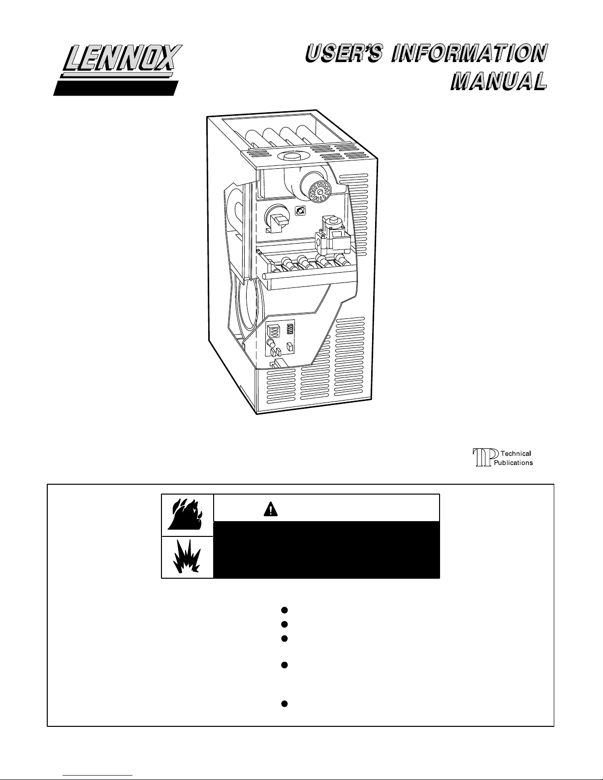
G24MCE
SERIES
GAS-FIRED
FURNACE
RETAIN THESE INSTRUCTIONS
FOR FUTURE REFERENCE
If the information in this manual is not
followed exactly, a fire or explosion
may result causing property damage,
personal injury or loss of life.
Do not store or use petrol or other
flammable vapours and liquids in the
vicinity of this or any other appliance.
Installation and service must be perĆ
formed by a qualified installer, serĆ
vice agency or the gas supplier.
Litho USA
WARNING
WHAT TO DO IF YOU SMELL GAS:
Do not try to light any appliance.
Extinguish any open flames.
Do not touch any electrical switch; do not
use any telephone in your building.
Immediately call your gas supplier from a
neighbor's telephone. Follow the gas supĆ
plier's instructions.
If you cannot reach your gas supplier, call
the local fire brigade.
Page 1
Page 2
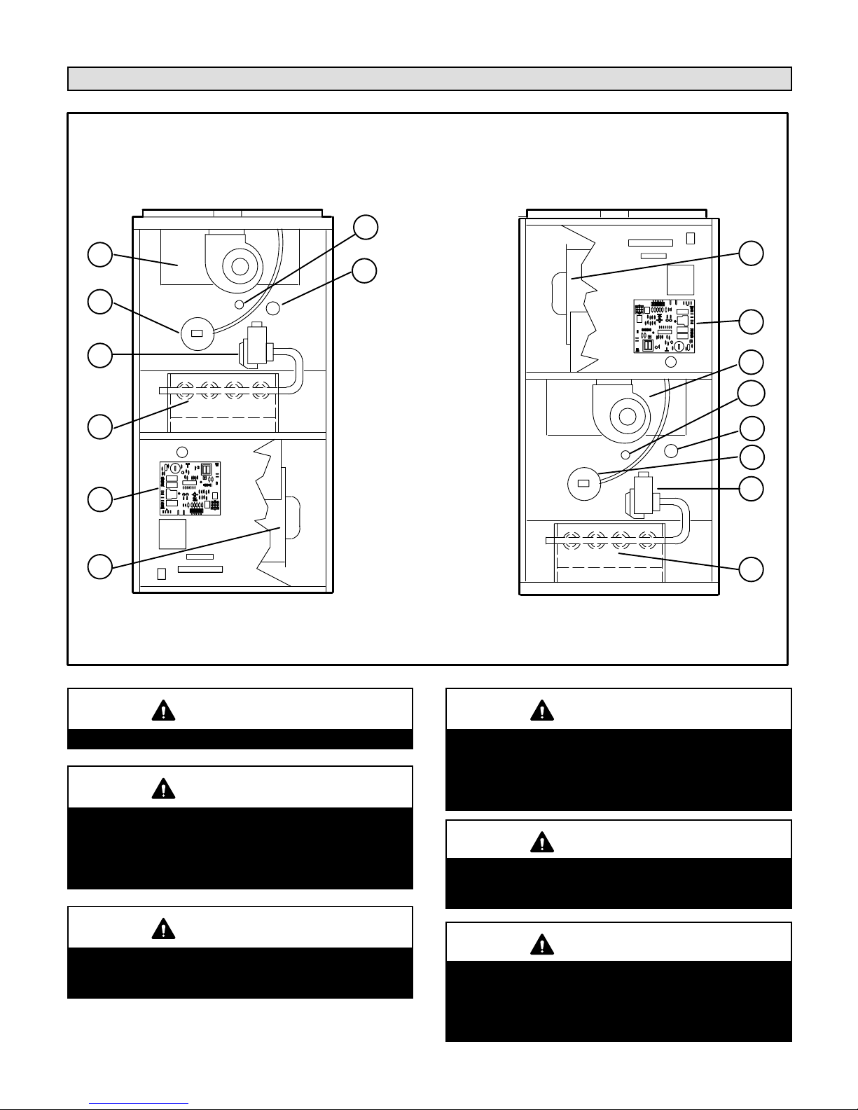
G24MCE Parts Identification
7
1
4
2
3
5
6
8
UPFLOW POSITION DOWNFLOW POSITION
1 - COMBUSTION AIR FAN
2 - PRESSURE SWITCH
3 - GAS VALVE
4 - CAPILLARY TUBE LIMIT
5 - BURNERS
6 - CONTROL BOARD
7 - HIGH LIMIT
8 - MAIN FAN
8
6
1
7
4
2
3
5
WARNING
This appliance must be earthed.
WARNING
This product contains glass fibre insulation.If inĆ
sulation is disturbed during installation, mainteĆ
nance or repair, persons may be exposed to irritaĆ
tion to the skin, eyes and lungs. Tears in the insulaĆ
tion should be repaired straight away.
WARNING
If overheating occurs or if gas supply fails to shut
off, shut off the manual gas valve to the appliance
before shutting off electrical supply.
WARNING
Do not use this furnace if any part has been underĆ
water. Immediately call a qualified service techniĆ
cian to inspect the furnace and to replace any part
of the control system and any gas control which
has been under water.
CAUTION
Before attempting to perform any service or mainteĆ
nance, turn the electrical power to unit OFF at isolaĆ
tor switch.
IMPORTANT
Any additions, changes, or conversions required in
order for the appliance to satisfactorily meet the apĆ
plication needs must be made by a Lennox service
technician using factory specified and approved
parts.
Page 2
Page 3

Important Directions
1 - Keep the furnace area clear and free of combustible
material, petrol, and other flammable vapours and liqĆ
uids. If installed in an insulated area, furnace must be
kept free of insulating material. Insulating material may
be combustible. Inspect furnace venting system to
make sure it is in place, physically sound, and without
holes, corrosion, or blockage. Inspect furnace return
air duct connection to ensure duct is sealed to the furĆ
nace and terminates outside the space containing the
furnace. Inspect the physical support of the furnace to
guarantee that it is sound without sagging, cracks or
gaps around base and it maintains seal between base
and support.
2 - DO NOT obstruct air flow to unit. Unit must receive an
unobstructed flow of combustion and ventilating air.
3 - DO NOT store chlorine or fluorine products near unit or
introduce these products into the combustion air.
These products can cause furnace corrosion.
4- DO NOT draw return air from a room where this
furnace, or any other gas appliance (ie., a water
heater), is installed. When return air is drawn from a
room, a negative pressure is created in the room. If a
gas appliance is operating in a room with negative
pressure, the flue products can be pulled back down
the vent pipe and into the room. This reverse flow of
the flue gas may result in incomplete combustion and
the formation of carbon monoxide gas. This toxic gas
might then be distributed throughout the house by
the furnace duct system.
Your furnace is a gas appliance. It is critical that the gas
supplied to the unit be completely burned to avoid the proĆ
duction of carbon monoxide gas. Complete combustion
of the gas requires, but is not limited to, correct gas presĆ
sure and gas flow rate, adequate combustion, air, and
proper venting.
WARNING
Carbon monoxide gas is invisible, odorless, and
toxic.
Exposure to this gas can cause personal injury and
even death to all occupants, including pets. Any item
th a t is power e d by or gi v e s off he at from a combustion
process (including lawn mowers, automobiles, and
fireplaces) has the potential to produce carbon monĆ
oxide gas. Because of this, Lennox recommends the
use of a carbon monoxide detector in your home,
even if you do not own gas appliances. Reliable deĆ
tectors are available at reasonable retail prices. ConĆ
tact your independent Lennox dealer for more details
about this investment in your safety.
Your furnace is designed to meet standards set by nationĆ
al agencies, and to operate safely when properly installed
and maintained. However, the unit's performance can be
greatly impacted by the individual installation and the opĆ
erating environment. It is your responsibility to ensure
that this appliance is maintained. Proper maintenance is
critical for your safety and the satisfactory operation of the
product. Lennox strongly recommends annual inĆ
spection and maintenance of this appliance. Contact
your independent Lennox dealer for an inspection by a
qualified service technician.
Page 3
Page 4

Lighting Information and Operation
WARNING
If you do not follow these instructions exactly, a fire
or explosion may result causing property damage,
personal injury or loss of life.
BEFORE LIGHTING smell all around the appliance area
for gas. Be sure to smell next to the floor because some
gas is heavier than air and will settle on the floor.
Filters
G24MCE series units are equipped with external filters
which should be inspected monthly and replaced when
necessary to assure proper furnace operation. See
table 1 for filter sizes. Replacement filters used with
G24MCE-4 0 / 60/75 uni t s must have a min i m um velocĆ
ity rat i n g of 2 m/s (400 FPM ) . Re p lac e ment fil t ers used
with G24MCE-100/120/140 units require a minimum
velocity rating of 3.2 m/s (625 FPM). Figures 2 and 3
show possible filter locations when the units are
installed in the upflow position.
Placing Furnace Into Operation
G24MCE units are equipped with an electronic ignition sysĆ
tem. Do not
attempt to manually light burners on these furĆ
naces. Each time the thermostat calls for heat, the burner
will automatically light.
THERMOSTATS
FIGURE 1
Gas Valve Operation
1 - STOP! Read the safety information at the beginning
of this section.
2 - Set the thermostat to lowest setting. See figure 1.
3 - Turn off all electrical power to the unit.
4 - This furnace Is equipped with an ignition device
which automatically lights the burner. Do not try to
light the burner by hand.
5 - Wait five (5) minutes to clear out any gas. If you then
smell gas, STOP! Immediately call your gas supplier
from a neighbor's phone. Follow the gas supplier's
instructions. If you do not smell gas go to next step.
6- Turn on all electrical power to the unit.
7- Set the thermostat to desired setting.
NOTE-When unit is first started, steps 1 through 7 may
need to be repeated to purge air from gas line.
8- If the appliance still will not operate, follow the
instructions Turning Off Gas To Unit" and call your
service technician or gas supplier.
Turning Off Gas To Unit
1 - Set the thermostat to the lowest setting.
2 - Turn off all electrical power to the unit if service is to
be performed.
MODEL NO.
G24MCE-45/60/75
G24MCE-100/120/140
UPFLOW FURNACE
BOTTOM RETURN AIR
TABLE 1
FILTER SIZE -
millimeters (inches)
406X508X25
(16 X 20 X 1)
508X508X25
(20 X 20 X 1)
FIGURE 2
Page 4
Page 5

UPFLOW FURNACE
SIDE RETURN AIR
BURNER FLAME
FIGURE 3
Fan
Check and clean fan wheel for any debris. Fan motor is
prelubricated for extended bearing life. No further lubricaĆ
tion is needed.
WARNING
FLAME APPEARS BLUE IF
BURNING NAT. GAS; BLUE/
YELLOW FOR PROPANE.
BURNER
FLAME
EXCHANGER
VEST
PANEL
HEAT
TUBE
FIGURE 4
Venting System Inspection
Annually (before heating season) inspect furnace venting
system, vent cap, heat exchanger and burners for corroĆ
sion, deterioration, or deposits of debris. Remove any obĆ
structions.
Contact your Lennox dealer for a periodic unit inspection
by a qualified gas service engineer.
Capillary Tube Limit Switch
Your Lennox furnace is equipped with a manuallyĆreset
capillary tube limit switch which shuts off the gas supply to
the furnace in the event of inadequate supply air (high air
temperature). It is located on the vestibule panel near the
gas valve. To reset this control, push the switch on the
face of the control sideways. If this switch opens again,
consult a qualified gas service engineer.
Fan door must be securely in place when fan and
burners are operating. Gas fumes, which could
contain carbon monoxide, can be drawn into living
space resulting in personal injury or death.
Burner Flame
The G24MCE burner flame is not adjustable; however,
the flame should be inspected at the beginning of each
heating season and burners should be cleaned, if necesĆ
sary. Burner flame should be blue when burning natural
gas, blue/yellow when burning propane gas.
Control Board Lockouts
Several types of control board lockout modes exist on this
furnace. When in one of these modes, the control board
will not allow the furnace to start. The two modes that can
be manually reset are: a Watchguard lockout mode," and
a Hard lockout mode."
To reset the Watchguard mode," manually switch the therĆ
mostat from HEAT to OFF and then back to HEAT again.
(Note - This lockout mode will also automatically reset after
a 60 minute lockout period.)
The Hard lockout mode" can be reset by turning the elecĆ
trical power OFF and then back ON again.
If either of these two lockouts reoccur, or if the original lockĆ
out cannot be reset, call a qualified gas service engineer.
Page 5
Page 6

Service Reminder
Call your Lennox service technician if unit is inoperative.
Before calling, always check the following to be sure serĆ
vice is required.
1 - Check that electrical isolator switches are ON.
2 - Check room thermostat for proper setting.
3 - Replace any blown fuses or reset circuit breakers.
4 - Air filter should not be clogged limiting air flow.
5 - Is gas turned on at meter?
6 - Is manual gas cock open?
To keep your Lennox gas heating system in peak
operating condition year after year, contact your
independent Lennox dealer about a planned service
program.
Safety Precautions
If you discover any of the following, shut down your
unit, and contact an independent Lennox dealer for
an inspection by a qualified technician.
S If you repeatedly hear any new or unfamiliar sounds
while your unit is operating, there may be a problem.
For example, poorly performing burners can produce
unfamiliar noises.
S If you smell any unusual odors, your unit may be operĆ
ating improperly. For example, units can give off unfaĆ
miliar odors if components are required to operate in
abnormal conditions.
S Look for visible signs of a malfunctioning unit. ExamĆ
ples include unusual amounts of condensate on winĆ
dows inside your house, visibly burnt components or
unusual dirt or rust accumulations on the vent pipe or
in the unit.
S If you experience headache, nausea, fatigue, or dizziĆ
ness, the cause could be exposure to carbon monoxĆ
ide gas. This is often misdiagnosed as the flu because
symptoms are similar. If you suffer from flu-like sympĆ
toms that are exaggerated at home, but seem to subĆ
side while you are away from the house, exposure to
carbon monoxide could be the cause.
Your vigilance may pay off in early detection of a problem
before either personal injury or property damage occurs.
Do not hesitate to contact a qualified service technician as
an investment in your well being.
Planned Service
You should expect a service technician to check the folĆ
lowing items during an annual inspection. Power to the
unit must be shut off for the service technician's safety.
Fresh air grilles and louvers (on the unit and in the room
where the furnace is installed) - Must be open and unobĆ
structed to provide combustion air.
Burners- Must be inspected for rust, dirt, or signs of waĆ
ter.
Vent pipe - Must be inspected for signs of water, damĆ
aged or sagging pipe, or disconnected joints.
Unit appearance - Must be inspected for rust, dirt, signs
of water, burnt or damaged wires, or components.
Fan access door - Must be properly in place and provide
a seal between the return air and the room where the furĆ
nace is installed.
Return air duct - Must be properly attached and provide
an air seal to unit.
Operating performance - Unit must be observed during
operation to monitor proper performance of the unit and
the vent system.
Combustion gases - Flue products must be analyzed
and compared to the unit specifications.
Problems detected during the inspection may make it
necessary to temporarily shut down the furnace until the
items can be repaired or replaced.
Pay attention to your furnace. Situations can arise beĆ
tween annual furnace inspections that may result in unĆ
safe operation. For instance, items innocently stored next
to the furnace may obstruct the combustion air supply.
This could cause incomplete combustion and the producĆ
tion of carbon monoxide gas.
Page 6
 Loading...