

Page 1
G24M
Blowerwheelnomina
l
Blowerwheelnomina
l
diameterxwidt
h
Nominalcoolin
g
Nominalcoolin
g
thatcanbeadde
d
¡
Down-flow
Corp. 9723-L12
Service Literature
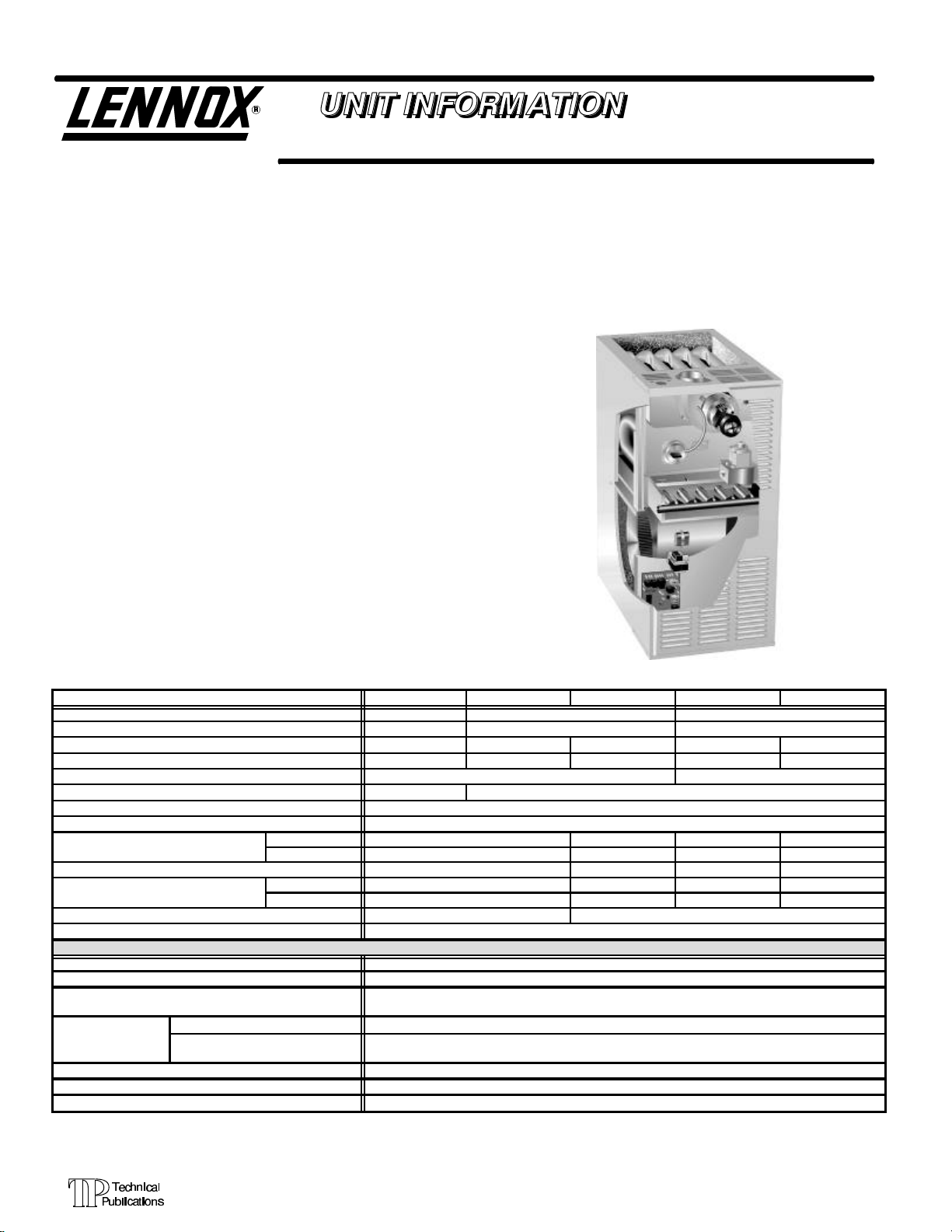
G24M SERIES UNITS
G24Mseriesunitsaremid-efficiencygasfurnacesmanufactured with tubular steel heat exchangers formed of aluminizedsteel.G24Munitsareavailableinheatingcapacitiesof
45,000 to 140,000 Btuh and cooling applications up to 5
tons. Refer to Engineering Handbook for proper sizing.
Units are factory equipped for use with natural gas. A kit is
availableforconversiontoLPGoperation.EarlymodelG24M
units use electronic (direct spark) ignition. Late model G24M
model units feature the Lennox SureLightT silicon-nitride
ignition system. The G24MX unit meets the California Nitrogen Oxides (NOx) Standards and California Seasonal Efficiency requirements. All units use a redundant gas valve to
assure safety shut-off as required by A.G.A. or C.G.A.
Unitsmaybeinstalledinupflow,downfloworhorizontalposition. The heat exchanger is designed for upright or horizontal use only. When the unit is installed in the downflow position,theheatexchangerisfieldremovedandreinstalled so it
isuprightwhen the cabinet is inverted.Nofield conversion is
required when the unit is installed in the horizontal position.
The heat exchanger, burners and manifold assembly can
easily be removed for inspection and service by simply disconnecting gas, unplugging wiring harness and spark wires
and removing four screws holding the heat exchanger in
place. Then the heat exchanger slides out of the cabinet.
Model No. G24M2(X)-45 G24M2-60 G24M3(X)-60 G24M2-75 G24M3(X)-75
Input Btuh (kW) 45,000 (13.2) 60,000 (17.6) 75,000 (22.0)
Output Btuh (kW) 36,900 (10.8) 49,200 (14.4) 61,700 (18.1)
lA.F.U.E. 80.1% 80.5% 80.5% 80.1% 80.0%
California Seasonal Efficiency 75.4% 76.4% 75.9% 76.8% 76.8%
Flue size connection diameter — in. (mm) round 3 (76) 4 (102)
Temperature rise range — _F (_C) 30 - 60 (17 - 33) 45 - 75 (25 - 42)
High static certified by A.G.A./C.G.A. — in wg. (Pa) .50 (125)
Gas Piping Size I.P.S. Natural or LPG/propane 1/2 (13)
in. 9 x 7 10 x 7 9 x 7 10 x 7
Blower motor output — hp (W) 1/4 (187) 1/3 (224) 1/4 (187) 1/3 (224)
Shipping weight — lbs. (kg) 1 package 130 (59) 135 (61)
Electrical characteristics 120 volts — 60 hertz — 1 phase (less than 12 amps) All models
LPG/propane kit LB-69845L (38K84)
Twinning Kit 96J69 — 5 lbs. (2 kg)
Up-Flow/Horizontal Filter and Filter Rack Kits
}No. & size of filters - in. (mm)
Catalog No.
Filter Kit
Down-flow Combustible Floor Base
Sidewall Power Venting Kit 79J15 — 25 lbs. (11 kg)
Hanging Bracket Kit
lAnnual Fuel Utilization Efficiency based on U.S. DOE test procedures and according to FTC labeling regulations. Isolated combustion system rating for non-weatherized
furnaces.
}Polyurethane frame type filter isfurnished with kit.
¡Filters arenot furnished with kitand must be ordered extra.
No. & Size of Filters — in. (mm)
mm 229 x 178 254 x 178 229 x 178 254 x 178
Tons 1, 1-1/2 or 2 2, 2-1/2 or 3 1, 1-1/2 or 2 2, 2-1/2 or 3
kW 3.5, 5.3 or 7.0 7.0, 8.8 or 10.6 3.5, 5.3 or7.0 7.0, 8.8 or 10.6
b Optional Accessories (Must Be Ordered Extra) b
Revised 07-2001
All specifications in this manual are subject to change. Procedures outlined in this manual are presented as a recommendation only and do not supersede or replace local or
state codes. In the absence of local or state codes, the
guidelines and procedures outlined in this manual (except
where noted) are recommended only and do not constitute
code.
SPECIFICATIONS
LB-69843A (32J01) — 3 lbs. (1 kg)
LB-79239A (67J91) — 10 lbs. (4 kg)
LB-69957 (46J66) — 15 lbs. (8 kg)
Single (32J02) TenPack (66K64)
(1) 16 x 20 x 1 (406 x 508 x 25)
(2) 16 x 20 x 1 (406 x 508 x 25)
Page 1
ã 1998 Lennox Industries Inc.
Litho U.S.A.
Page 2
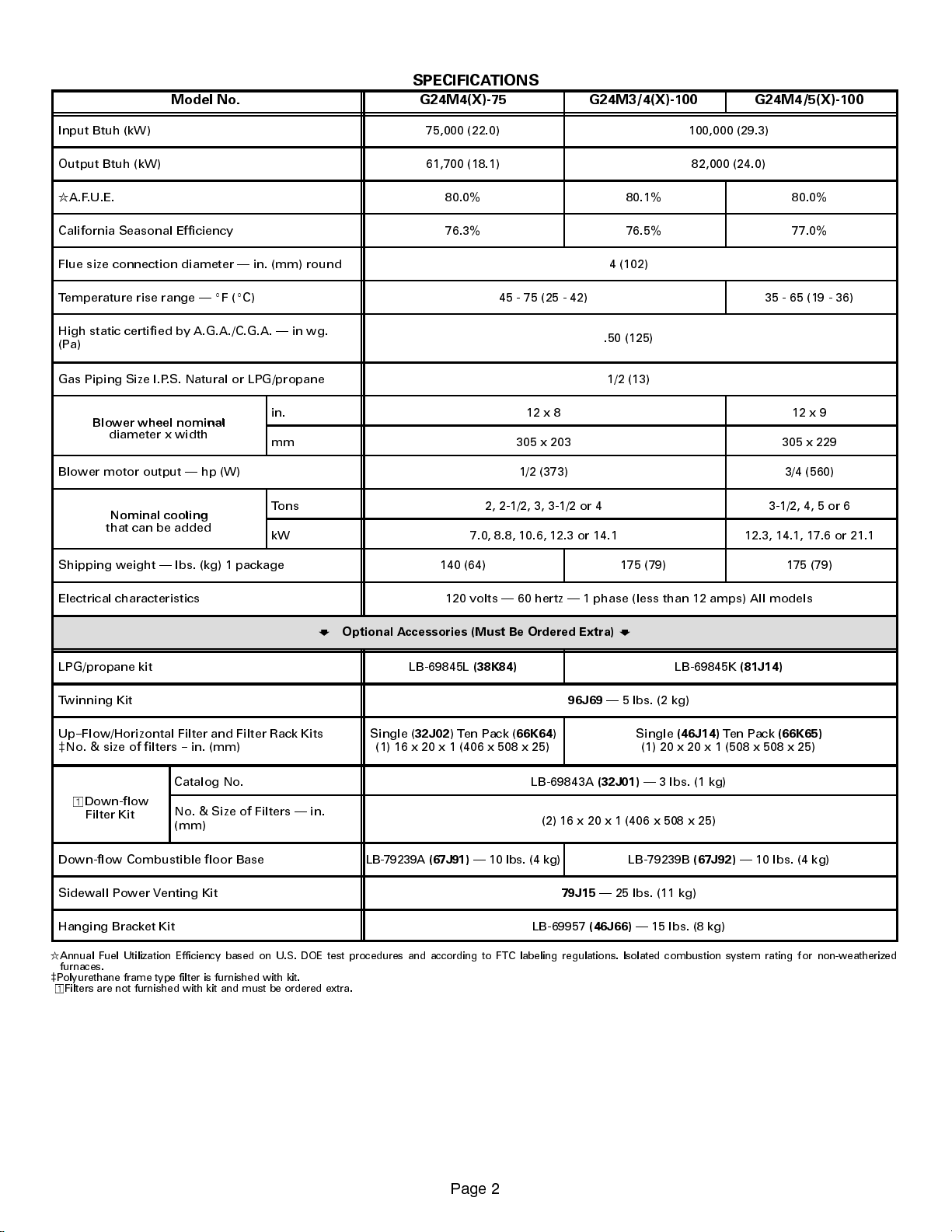
SPECIFICATIONS
Bl
l
Nominal
Model No. G24M4(X)-75 G24M3/4(X)-100 G24M4/5(X)-100
Input Btuh (kW) 75,000 (22.0) 100,000 (29.3)
Output Btuh (kW) 61,700 (18.1) 82,000 (24.0)
R
A.F.U.E. 80.0% 80.1% 80.0%
California Seasonal Efficiency 76.3% 76.5% 77.0%
Flue size connection diameter in. (mm) round 4 (102)
Temperature rise range EF(EC) 45 - 75 (25 - 42) 35 - 65 (19 - 36)
High static certified by A.G.A./C.G.A. in wg.
(Pa)
.50 (125)
Gas Piping Size I.P.S. Natural or LPG/propane 1/2 (13)
ower wheelnomina
diameter x width
in. 12 x 8 12 x 9
mm 305 x 203 305 x 229
Blower motor output hp (W) 1/2 (373) 3/4 (560)
that can be added
cooling
Tons 2, 2-1/2, 3, 3-1/2 or 4 3-1/2, 4, 5 or 6
kW 7.0, 8.8, 10.6, 12.3 or 14.1 12.3, 14.1, 17.6 or 21.1
Shipping weight lbs. (kg) 1 package 140 (64) 175 (79) 175 (79)
Electrical characteristics 120 volts 60 hertz 1 phase (less than 12 amps) All models
H
Optional Accessories (Must Be Ordered Extra)
LPG/propane kit LB-69845L
Twinning Kit
Up--Flow/Horizontal Filter and Filter Rack Kits
c
No. & size of filters -- in. (mm)
Single (
32J02
) Ten Pack (
(1) 16 x 20 x 1 (406 x 508 x 25)
(38K84)
66K64
96J69
)
H
LB-69845K
5 lbs. (2 kg)
Single
(46J14)
Ten Pack
(1) 20 x 20 x 1 (508 x 508 x 25)
(81J14)
(66K65)
Catalog No. LB-69843A
o
Down-flow
Filter Kit
Down-flow Combustible floor Base LB-79239A
Sidewall Power Venting Kit
Hanging Bracket Kit LB-69957
R
Annual Fuel Utilization Efficiency based on U.S. DOE test procedures and according to FTC labeling regulations. Isolated combustion system rating for non-weatherized
furnaces.
c
Polyurethane frame type filter is furnished with kit.
o
Filters are not furnished with kit and must be ordered extra.
No. & Size of Filters in.
(mm)
(2) 16 x 20 x 1 (406 x 508 x 25)
10lbs.(4kg) LB-79239B
(67J91)
79J15
(46J66)
3DJH
3 lbs. (1 kg)
(32J01)
25 lbs. (11 kg)
15 lbs. (8 kg)
(67J92)
10 lbs. (4 kg)
Page 3
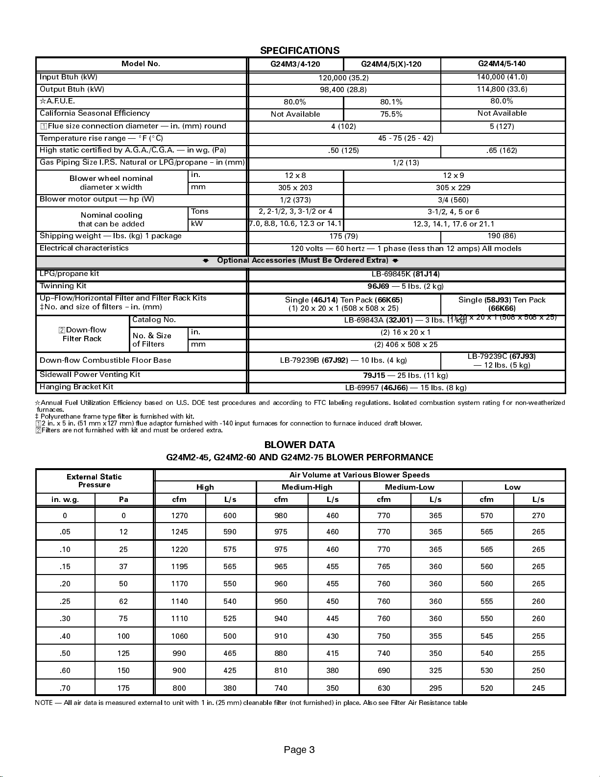
SPECIFICATIONS
Blower wheel nominal
g
Nominal cooling
No.& Size
External Static
Model No.
Input Btuh (kW)
Output Btuh (kW)
R
A.F.U.E.
California Seasonal Efficiency
o
Flue size connection diameter in. (mm) round
Temperature rise range EF(EC)
High static certified by A.G.A./C.G.A. in wg. (Pa)
Gas Piping Size I.P.S. Natural or LPG/propane -- in (mm)
Blower wheel nominal
diameter x width
in.
mm
Blower motor output hp (W)
Nominal coolin
that can be added
Tons 2, 2-1/2, 3, 3-1/2 or 4
kW 7.0, 8.8, 10.6, 12.3 or 14.1
Shipping weight lbs. (kg) 1 package
Electrical characteristics
H
Optional Accessories (Must Be Ordered Extra)
LPG/propane kit
Twinning Kit
Up--Flow/Horizontal Filter and Filter Rack Kits
c
No. and size of filters -- in. (mm)
Catalog No.
w
Down-flow
Filter Rack
No. & Size
of Filters
in.
mm
Down-flow Combustible Floor Base
Sidewall Power Venting Kit
Hanging Bracket Kit
R
Annual Fuel Utilization Efficiency based on U.S. DOE test procedures and according to FTC labeling regulations. Isolated combustion system rating for non-weatherized
furnaces.
c
Polyurethane frame type filter is furnished with kit.
o
2 in. x 5 in. (51 mm x127 mm) flue adaptor furnished with -140 input furnaces for connection to furnace induced draft blower.
w
Filters are not furnished with kit and must be ordered extra.
G24M3/4-120 G24M4/5(X)-120
120,000 (35.2)
98,400 (28.8)
80.0% 80.1%
Not Available 75.5%
4 (102) 5 (127)
45 - 75 (25 - 42)
.50 (125) .65 (162)
1/2 (13)
12 x 8 12x9
305 x 203 305 x 229
1/2 (373) 3/4 (560)
3-1/2, 4, 5 or 6
12.3, 14.1, 17.6 or 21.1
175 (79)
120 volts 60 hertz 1 phase (less than 12 amps) All models
H
Single
(46J14)
Ten Pack
LB-69845K
96J69
(66K65)
(81J14)
5 lbs. (2 kg)
(1) 20 x 20 x 1 (508 x 508 x 25)
LB-69843A
(32J01)
3 lbs. (1 kg)
(1) 20 x 20 x 1 (508 x 508 x 25)
(2)16x20x1
(2) 406 x 508 x 25
LB-79239B
(67J92)
10 lbs. (4 kg)
25 lbs. (11 kg)
79J15
LB-69957
(46J66)
15 lbs. (8 kg)
G24M4/5-140
140,000 (41.0)
114,800 (33.6)
80.0%
Not Available
190 (86)
Single
(58J93)
(66K66)
LB-79239C
12 lbs. (5 kg)
Ten Pack
(67J93)
BLOWER DATA
G24M2-45, G24M2-60 AND G24M2-75 BLOW
ER PERFORMANCE
External Static
Pressure
High Medium-High Medium-Low Low
Air Volume at Various Blower Speeds
in. w.g. Pa cfm L/s cfm L/s cfm L/s cfm L/s
0 0 1270 600 980 460 770 365 570 270
.05 12 1245 590 975 460 770 365 565 265
.10 25 1220 575 975 460 770 365 565 265
.15 37 1195 565 965 455 765 360 560 265
.20 50 1170 550 960 455 760 360 560 265
.25 62 1140 540 950 450 760 360 555 260
.30 75 1110 525 940 445 760 360 550 260
.40 100 1060 500 910 430 750 355 545 255
.50 125 990 465 880 415 740 350 540 255
.60 150 900 425 810 380 690 325 530 250
.70 175 800 380 740 350 630 295 520 245
NOTE All air data is measured external to unit with 1 in. (25 mm) cleanable filter (not furnished) in place. Also see Filter Air Resistance table
3DJH
Page 4
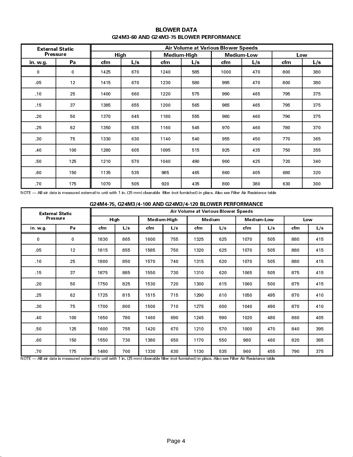
BLOWER DATA
External Static
External Static
G24M3-60 AND G24M3-75 BLOWER PERFORMANCE
Air Volume at Various Blower Speeds
Pressure
in. w.g. Pa cfm L/s cfm L/s cfm L/s cfm L/s
0 0 1425 670 1240 585 1000 470 800 380
.05 12 1415 670 1230 580 995 470 800 380
.10 25 1400 660 1220 575 990 465 795 375
.15 37 1385 655 1200 565 985 465 795 375
.20 50 1370 645 1180 555 980 460 790 375
.25 62 1350 635 1160 545 970 460 780 370
.30 75 1330 630 1140 540 955 450 770 365
.40 100 1280 605 1095 515 925 435 750 355
.50 125 1210 570 1040 490 900 425 720 340
.60 150 1135 535 985 465 860 405 680 320
.70 175 1070 505 920 435 800 380 630 300
NOTE All air data is measured external to unit with 1 in. (25 mm) cleanable filter (not furnished) in place. Also see Filter Air Resistance table
High Medium-High Medium-Low Low
G24M4-75, G24M3/4-100 AND G24M3/4-120 BLOWER PERFORMANCE
External Static
Pressure
in. w.g. Pa cfm L/s cfm L/s cfm L/s cfm L/s cfm L/s
0 0 1830 865 1600 755 1325 625 1070 505 880 415
.05 12 1815 855 1585 750 1320 625 1070 505 880 415
.10 25 1800 850 1570 740 1315 620 1070 505 880 415
.15 37 1875 885 1550 730 1310 620 1065 505 875 415
.20 50 1750 825 1530 720 1300 615 1060 500 875 415
.25 62 1725 815 1515 715 1290 610 1050 495 870 410
.30 75 1700 800 1500 710 1275 600 1040 490 870 410
.40 100 1650 780 1460 690 1245 590 1020 480 860 405
.50 125 1600 755 1420 670 1210 570 1000 470 840 395
.60 150 1550 730 1380 650 1170 550 980 460 820 385
.70 175 1480 700 1330 630 1130 535 960 455 790 375
NOTE All air data is measured external to unit with 1 in. (25 mm) cleanable filter (not furnished) in place. Also see Filter Air Resistance table
High Medium-High Medium Medium-Low Low
Air Volume at Various Blower Speeds
3DJH
Page 5
BLOWER DATA
External Static
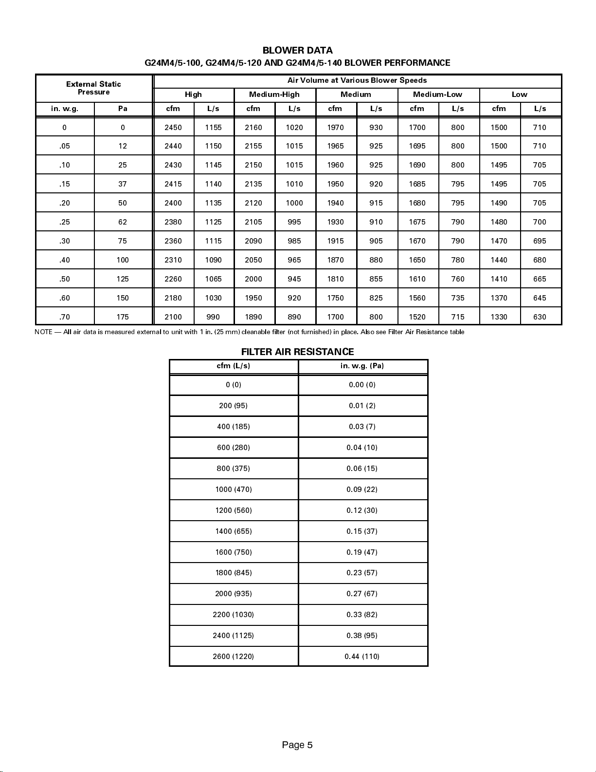
G24M4/5-100, G24M4/5-120 AND G24M4/5-140 BLOWER PERFORMANCE
External Static
Pressure
in. w.g. Pa cfm L/s cfm L/s cfm L/s cfm L/s cfm L/s
0 0 2450 1155 2160 1020 1970 930 1700 800 1500 710
.05 12 2440 1150 2155 1015 1965 925 1695 800 1500 710
.10 25 2430 1145 2150 1015 1960 925 1690 800 1495 705
.15 37 2415 1140 2135 1010 1950 920 1685 795 1495 705
.20 50 2400 1135 2120 1000 1940 915 1680 795 1490 705
.25 62 2380 1125 2105 995 1930 910 1675 790 1480 700
.30 75 2360 1115 2090 985 1915 905 1670 790 1470 695
.40 100 2310 1090 2050 965 1870 880 1650 780 1440 680
.50 125 2260 1065 2000 945 1810 855 1610 760 1410 665
.60 150 2180 1030 1950 920 1750 825 1560 735 1370 645
.70 175 2100 990 1890 890 1700 800 1520 715 1330 630
NOTE All air data is measured external to unit with 1 in. (25 mm) cleanable filter (not furnished) in place. Also see Filter Air Resistance table
High Medium-High Medium Medium-Low Low
Air Volume at Various Blower Speeds
FILTER AIR RESISTANCE
cfm (L/s) in. w.g. (Pa)
0 (0) 0.00 (0)
200 (95) 0.01 (2)
400 (185) 0.03 (7)
600 (280) 0.04 (10)
800 (375) 0.06 (15)
1000 (470) 0.09 (22)
1200 (560) 0.12 (30)
1400 (655) 0.15 (37)
1600 (750) 0.19 (47)
1800 (845) 0.23 (57)
2000 (935) 0.27 (67)
2200 (1030) 0.33 (82)
2400 (1125) 0.38 (95)
2600 (1220) 0.44 (110)
3DJH
Page 6
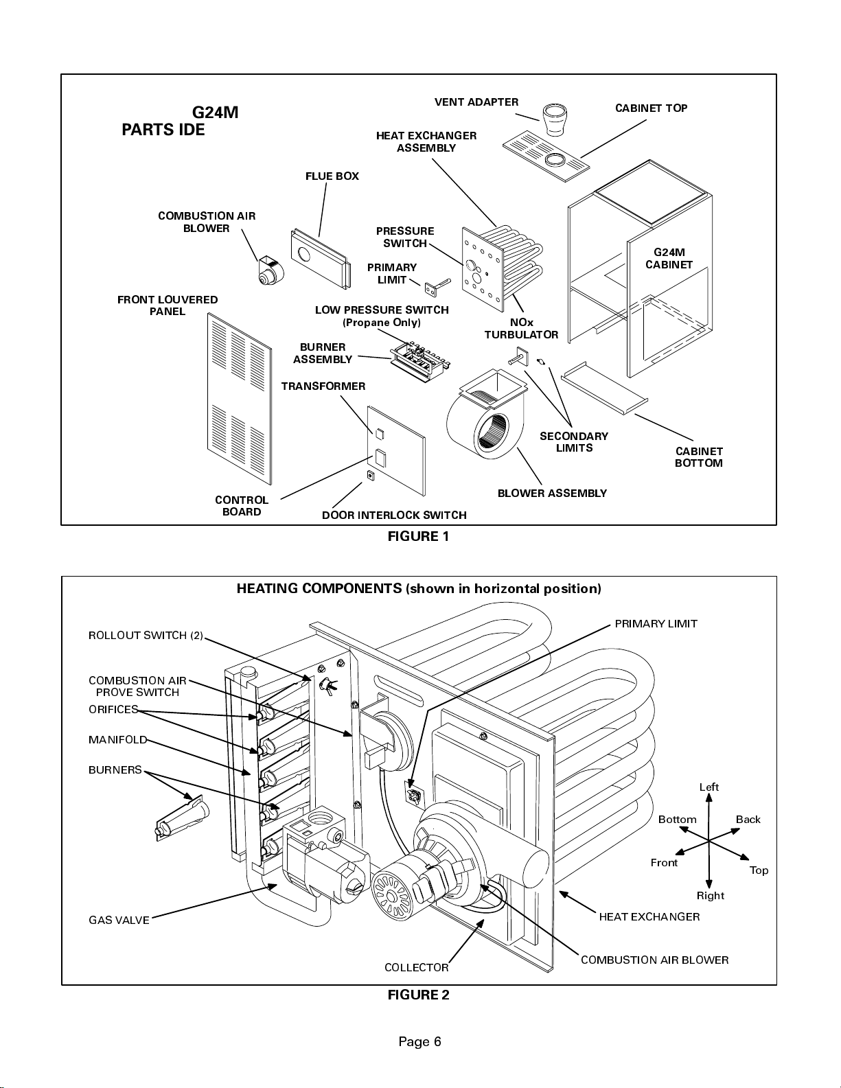
G24M
PARTS IDENTIFICATION
COMBUSTION AIR
BLOWER
FRONT LOUVERED
PANEL
TRANSFORMER
HEAT EXCHANGER
FLUE BOX
PRESSURE
SWITCH
PRIMARY
LIMIT
LOW PRESSURE SWITCH
(Propane Only)
BURNER
ASSEMBLY
VENT ADAPTER
ASSEMBLY
NOx
TURBULATOR
SECONDARY
LIMITS
CABINET TOP
G24M
CABINET
CABINET
BOTTOM
ROLLOUT SWITCH (2)
COMBUSTION AIR
PROVE SWITCH
ORIFICES
MANIFOLD
BURNERS
CONTROL
BOARD
DOOR INTERLOCK SWITCH
FIGURE 1
HEATING COMPONENTS (shown in horizonta
BLOWER ASSEMBLY
l position)
PRIMARY LIMIT
Bottom
Front
Left
Back
Top
GAS VALVE
COLLECTOR
FIGURE 2
Page 6
Right
HEAT EXCHANGER
COMBUSTION AIR BLOWER
Page 7
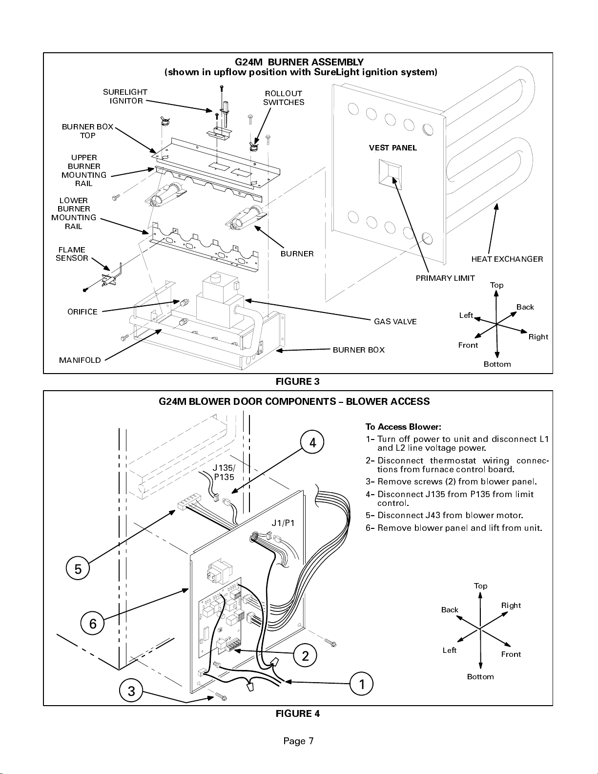
(shown in upflow position with SureLight ignition system)
G24M BURNER ASSEMBLY
BURNER BOX
TOP
UPPER
BURNER
MOUNTING
RAIL
LOWER
BURNER
MOUNTING
RAIL
FLAME
SENSOR
ORIFICE
MANIFOLD
SURELIGHT
IGNITOR
ROLLOUT
SWITCHES
BURNER
VEST PANEL
GAS VALVE
BURNER BOX
PRIMARY LIMIT
Left
Front
HEAT EXCHANGER
Top
Back
Right
Bottom
FIGURE 3
G24M BLOWER DOOR COMPONENTS -- BLOWER ACCESS
To Access Blower:
4
J135/
P135
J1/P1
1-- Turn off power to unit and disconnect L1
and L2 line voltage power.
2-- Disconnect thermostat wiring connec-
tions from furnace control board.
3-- Remove screws (2) from blower panel.
4-- Disconnect J135 from P135 from limit
control.
5-- Disconnect J43 from blower motor.
6-- Remove blower panel and lift from unit.
5
Top
Back
Right
6
2
Left
Front
Bottom
3
1
FIGURE 4
Page 7
Page 8
I-UNIT COMPONENTS (Figures 1, 2, 3)
G24M unit components are shown in figure 1. The blower
controls, gas valve and burners can be accessed by reĆ
moving the front access panel. A separate blower access
door is located behind the front access panel. Electrical
control components are mounted to the blower access
door.
G24M units are factory equipped with bottom return air panels
in place. The panels are designed to be field removed as reĆ
quired for bottom air return. Indentations on side of units,
show where side return opening should be cut during installaĆ
tion.
A-Blower Door Components (Figure 4)
Electrical burner control and blower control components
are located on the outside surface of the blower access
door. Jackplugs allow the blower door to be easily reĆ
moved for blower service.
Located on the blower door are the unit transformer (T1),
the furnace control (A3) and door interlock switch (S51).
Furnace control (A3) combines the function of a burner
ignition control and blower control.
1- Control Transformer (T1)
A transformer located on the blower door provides power
to the low voltage section of the unit. Transformers on all
models are rated 30VA with a 120V primary and a 24V secĆ
ondary.
2-Door Interlock Switch (S51)
A door interlock switch rated 16A at 125VAC is located on
the blower access door. The switch is wired in series with
line voltage. When the blower door is removed the unit will
shut down.
DANGER
Shock hazard.
Disconnect power before servicing. Control is not
field repairable. If control is inoperable, simply
replace entire control.
Can cause injury or death. Unsafe operation will
result if repair is attempted.
3- SureLight Ignition System (A3)
Late Model G24M Units
Late model G24M units are equipped with the Lennox
SureLight ignition system. The system consists of ignitor
(f igur e 5) and ignition control board (f igur e 6 wit h control
terminal designations in table 1). The board and ignitor
work in combination to ensure furnace ignition and ignitor
durability. The SureLight integrated board controls all
major furnace operations. The board also features two
LED lights for troubleshooting and two accessory termiĆ
nals rated at (4) four amps. See table 2 for troubleshootĆ
ing diagnostic codes. Table 3 and 4 show jack plug termiĆ
nal designations. Units equipped with the SureLight
board can be used with either electronic or electro-meĆ
chanical thermostats without modification. The SurĆ
eLight ignitor is made of durable silicon-nitride. Ignitor
longevity is also enhanced by voltage ramping by the
control board. The board finds the lowest ignitor temperaĆ
ture which will successfully light the burner, thus increasĆ
ing the life of the ignitor.
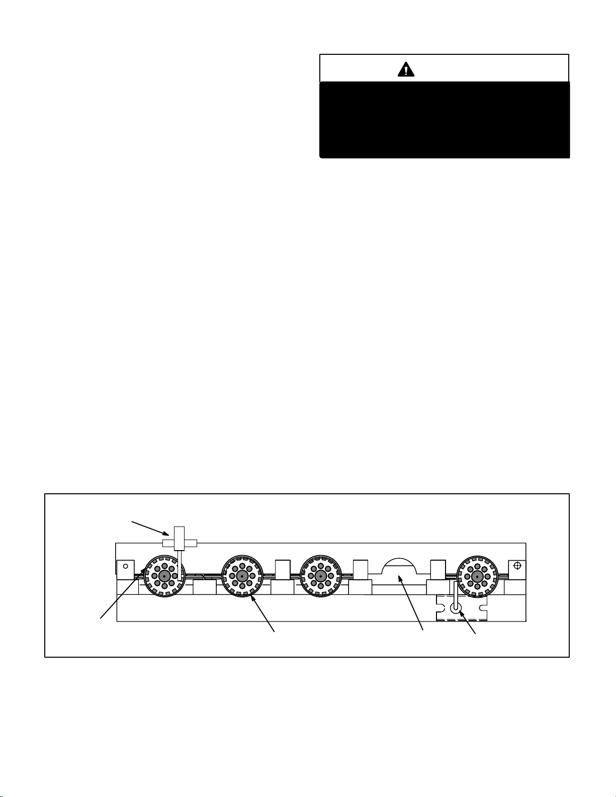
a-flame sensor
The flame sensor uses flame rectification to sense comĆ
bustion. During operation, flame is sensed by current
passed through the flame and sensing electrode. Figure 7
shows the gap between tip of the electrode and the burner
surface.
SURELIGHT IGNITOR
UPPER BURNER
MOUNTING RAIL
SURELIGHT IGNITOR BURNER ASSEMBLY
FLAME RETENTION RING
FIGURE 5
Page 8
ORIFICE
FLAME SENSOR
Page 9
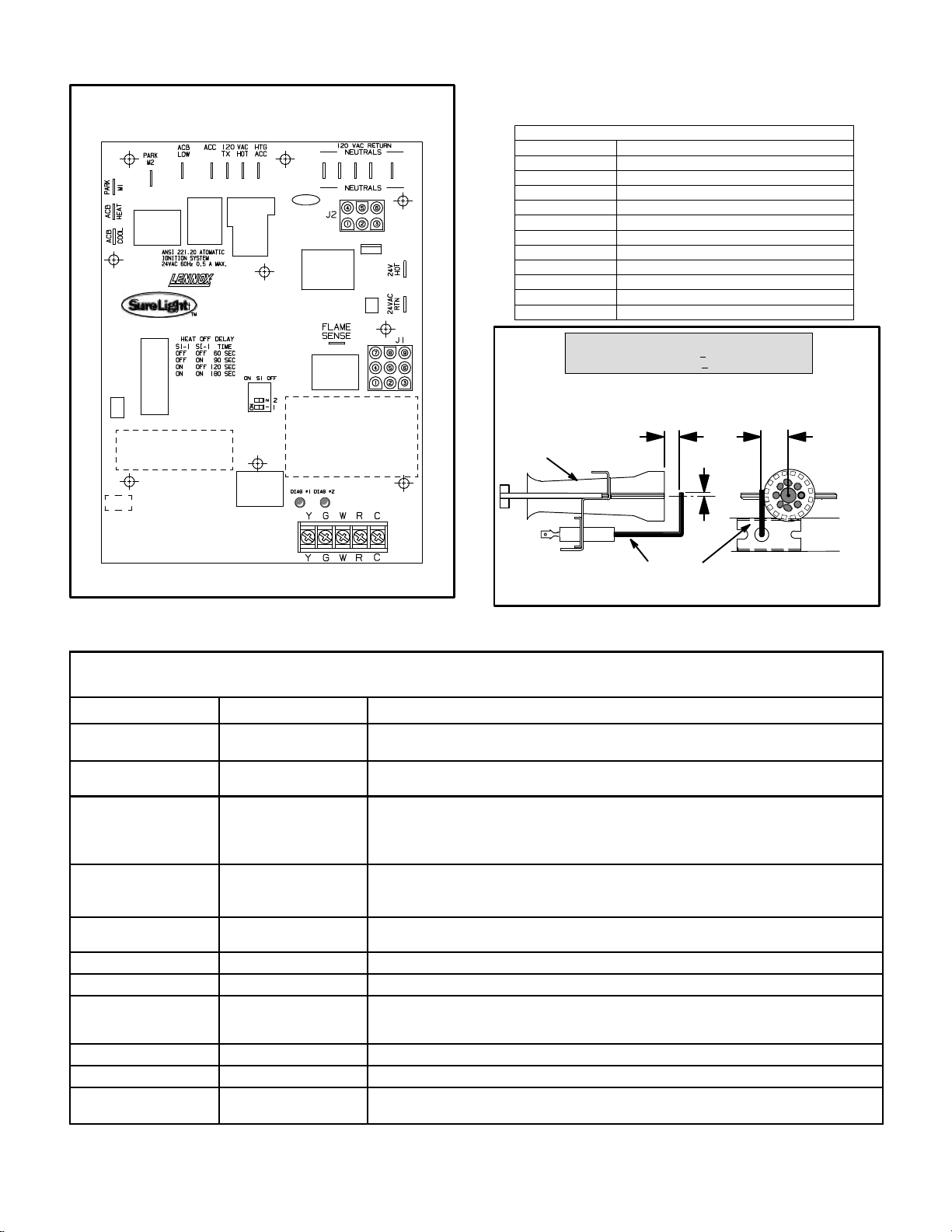
SURELIGHT CONTROL BOARD
LATE MODEL G24M UNITS
TABLE 1
SURELIGHT CONTROL TERMINAL DESIGNATIONS
ACB COOL
ACB HEAT
PARK
ACB LOW
ACC
TX
HOT
HTG ACC
NEUTRALS
24VACHOT
24VACRTN
FLAME SENSE
Blower - Cooling Speed (Line Volt)
Blower - Heating Speed (Line Volt)
Alternate Blower Speeds (Dead)
Continuous Low Speed Blower
Accessory Terminal (Line Volt)
120VACHot to Transformer
120VACHot Input
Heat Only Accessory (Line Volt)
120VACNeutrals
24VACHot from Transformer
24VACReturn from Transformer
Flame Sense Terminal
NORMAL FLAME SIGNAL > 0.7 MICROAMPS
LOW FLAME SIGNAL < 0.7 MICROAMPS
MINIMUM FLAME SIGNAL < 0.15 MICROAMPS
FLAME SENSOR TO BURNER GAP
1/4 in. 7 mm
¦ 1/32 in. 0.79
BURNER
SIDE VIEW END VIEW
FIGURE 6
TABLE 2
DIAGNOSTIC CODES
MAKE SURE TO ID LED’S CORRECTLY: REFER TO INSTALLATION INSTRUCTIONS FOR CONTROL BOARD LAYOUT.
LED #1 LED #2 DESCRIPTION
SIMULTANEOUS
SLOW FLASH
SIMULTANEOUS FAST
FLASH
SLOW FLASH ON
OFF SLOW FLASH
ALTERNATING SLOW
FLASH
SLOW FLASH OFF
ON SLOW FLASH
ON
ON
OFF
FAST FLASH SLOW FLASH
SLOW FLASH FAST FLASH
ALTERNATING FAST
FLASH
SIMULTANEOUS
SLOW FLASH
SIMULTANEOUS FAST
ALTERNATING SLOW
ALTERNATING FAST
FLASH
FLASH
ON
OFF
ON
FLASH
Also signaled during cooling and continues fan.
Normal operation - signaled when heating demand initiated at thermostat.
Primary or Secondary limit open. Units with board 63K8901 or 24L85: Limit must
close within 5 trials for ignition or board goes into one hour limit Watchguard.
Units with board 56L83 or 97L48: Limit must close within 3 minutes or board
Pressure switch open or has opened 5 times during a single call for heat; OR:
Blocked inlet/exhaust vent; OR: Condensate line blocked; OR: Pressure switch
closed prior to activation of combustion air blower.
Flame sensed without gas valve energized.
Rollout switch open. OR: 9 pin connector improperly attached.
Circuit board failure or control wired incorrectly.
Main power polarity reversed. Switch line and neutral.
Low flame signal. Measures below .7 microAmps. Replace flame sense rod.
Improper main ground or line voltage below 75 volts; OR: Broken ignitor; OR:
Power - Normal operation
goes into one hour limit Watchguard.
Watchguard - burners fail to ignite.
Open ignitor circuit.
mm
3/16 in.
4.7 mm
FLAME
SENSOR
FIGURE 7
11/16in. 18 mm
¦ 1/32 in. 0.79
mm
NOTE - Slowflash equals1 Hz (oneflash persecond). Fast flashequals 3Hz (threeflashes per second).Drop outflame sense current< 0.15microAmps
Page 9
Page 10
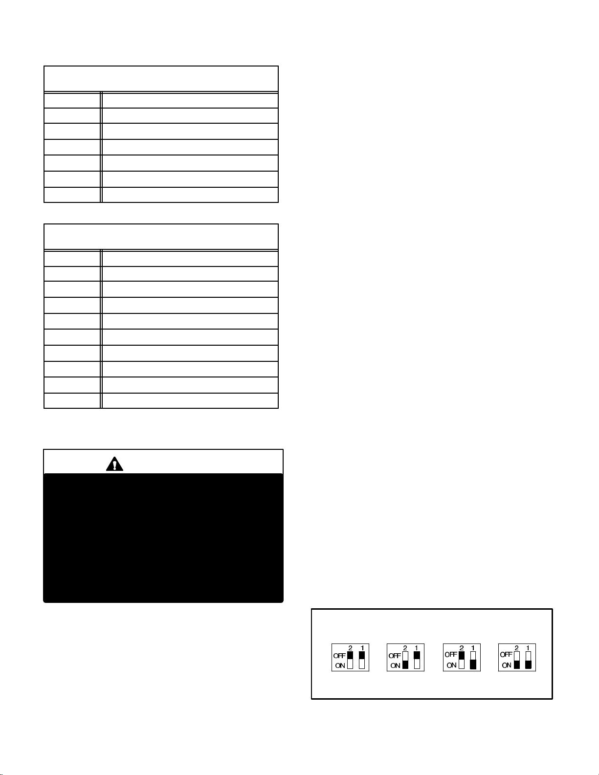
TABLE 3
SureLight BOARD J156 (J2) TERMINAL
PIN # FUNCTION
1 Ignitor
2
3
4
5
6
DESIGNATIONS
Not Used
Ignitor Neutral
Combustion Air Blower Line Voltage
Not Used
Combustion Air Blower Neutral
TABLE 4
SureLight BOARD J58 (J1) TERMINAL
PIN # FUNCTION
1 Primary Limit In
2
3
4
5
6
7
8
9
DESIGNATIONS
Gas Valve Common
Roll Out Switch Out
Gas Valve 24V
Pressure Switch In
Pressure Switch and Primary Limit Out
Not Used
Roll Out Switch In
Ground
ELECTROSTATIC DISCHARGE (ESD)
Precautions and Procedures
CAUTION
Electrostatic discharge can affect electronic
components. Take precautions during furnace
installation and service to protect the furnace’s
electronic controls. Precautions will help to
avoid control exposure to electrostatic discharge by putting the furnace, the control and
the technician at the same electrostatic potential. Neutralize electrostatic charge by touching
hand and all tools on an unpainted unit surface,
such as thegas valve or blower deck, before performing any service procedure.
not proven within 2-1/2 minutes, the control goes into
Watchguard-Pressure Switch mode for a 5-minute re-set
period.
NOTE - The G24M furnace contains electronic components that are polarity sensitive. Make sure that the
furnace is wired correctly and is properly grounded.
After the 15-second pre-purge period, the SureLight ignitor warms up for 20 seconds after which the gas valve
opensfor a 4-secondtrial for ignition.The ignitor staysenergized for the first second of the 4-second trial. G24M
units with 63K89, 24L85 or 56L83: the ignitor stays energizedthefirstsecondofthe4secondtrial.G24Munitswith
board 97L48: ignitor stays energized during the 4-second
trialuntilflameissensed.Ifignitionisnotproved during the
4-secondperiod,thecontrolwill try four more times withan
inter purge and warm-up time between trials of 35 seconds.After a totalof five trialsfor ignition (including the initial trial), the control goes into Watchguard-Flame Failure
mode.Aftera 60-minute reset period, the control willbegin
the ignition sequence again.
The SureLight control board has an added feature that
prolongs the life of the ignitor. After a successful ignition,
theSureLightcontrolutilizeslesspower to energize the ignitoron successive callsfor heat. Thecontrol continues to
rampdown the voltageto the ignitor untilit finds the lowest
amount of power that will provide a successful ignition.
Thisamount of poweris used for255 cycles. Onthe 256th
callfor heat, thecontrol will againramp down until the lowest power is determined and the cycle begins again.
c-Fan Time Control
The fan on time of 45 seconds is not adjustable. Fan off
time (time that the blower operates after the heat demand
has been satisfied) can be adjusted by flipping the dip
switches located on the SureLight integrated control. The
unit is shipped with a factory fan off setting of 90 seconds.
Fan off time will affect comfort and is adjustable to satisfy
individual applications. See figure 8.
NOTE—If fan “off” time is set too low, residual heat in
heat exchanger may cause primary limit S10 to trip resulting in frequent cycling of blower. If this occurs, adjust blower to longer time setting.
b-Electronic Ignition
On a call for heat the SureLight control monitors the combustion air inducer prove switch. The control will not begin
theheatingcycle if the prove switchisclosed (by-passed).
Once the prove switch is determined to be open, the combustion air inducer is energized. When the differential in
the prove switch is great enough, the prove switch closes
and a 15-second pre-purge begins. If the prove switch is
FAN-OFF TIME ADJUSTMENT
60sec. 90sec. 120sec. 180sec.
To adjust fan-off timing, flip dip switch to desired setting.
FIGURE 8
Page 10
Page 11
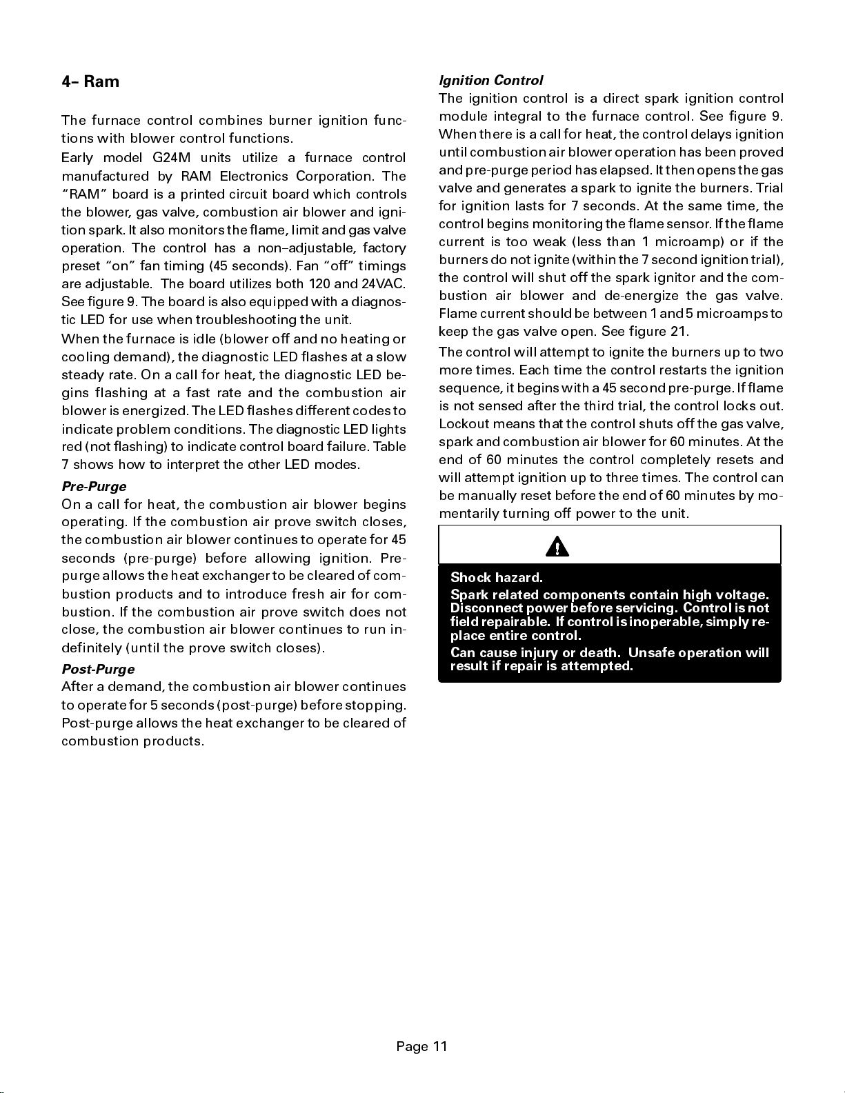
4-- Ram Control (A3)
Early Model G24M Units
The furnace control combines burner ignition func-
tions with blower control functions.
Early model G24M units utilize a furnace control
manufactured by RAM Electronics Corporation. The
RAM board is a printed circuit board which controls
the blower , gas valve, combustion air blower and igni-
tion spark. It also monitors the flame, limit and gas valve
operation. The control has a non--adjustable, factory
preset on fan timing (45 seconds). Fan off timings
are adjustable. The board utilizes both 120 and 24VAC.
See figure 9. The board is also equipped with a diagnos-
tic LED for use when troubleshooting the unit.
When the furnace is idle (blower off and no heating or
cooling demand), the diagnostic LED flashes at a slow
steady rate. On a call for heat, the diagnostic LED be-
gins flashing at a fast rate and the combustion air
blowerisenergized.The LED flashes different codes to
indicate problem conditions. The diagnostic LED lights
red (not flashing) to indicate control board failure. T able
7 shows how to interpret the other LED modes.
Pre-Purge
On a call for heat, the combustion air blower begins
operating. If the combustion air prove switch closes,
the combustion air blower continues to operate for 45
seconds (pre-purge) before allowing ignition. Pre-
purge allows the heat exchanger to be cleared of com-
bustion products and to introduce fresh air for com-
bustion. If the combustion air prove switch does not
close, the combustion air blower continues to run in-
definitely (until the prove switch closes).
Post-Purge
After a demand, the combustion air blower continues
to operate for 5 seconds (post-purge) before stopping.
Post-purge allows the heat exchanger to be cleared of
combustion products.
Ignition Control
The ignition control is a direct spark ignition control
module integral to the furnace control. See figure 9.
When there is a call for heat, the control delays ignition
until combustion air blower operation has been proved
and pre-purge period has elapsed. It then opens the gas
valve and generates a spark to ignite the burners. T rial
for ignition lasts for 7 seconds. At the same time, the
control begins monitoring the flame sensor.Iftheflame
current is too weak (less than 1 microamp) or if the
burners do not ignite (within the 7 second ignition trial),
the control will shut off the spark ignitor and the com-
bustion air blower and de-energize the gas valve.
Flame current should be between 1and5microamps to
keep the gas valve open. See figure 21.
The control will attempt to ignite the burners up to two
more times. Each time the control restarts the ignition
sequence, it begins with a 45 second pre-purge. If flame
is not sensed after the third trial, the control locks out.
Lockout means that the control shuts off the gas valve,
spark and combustion air blower for 60 minutes. At the
end of 60 minutes the control completely resets and
will attempt ignition up to three times. The control can
be manually reset before the end of 60 minutes by mo-
mentarily turning off power to the unit.
DANGER
Shock hazard.
Spark related components contain high voltage.
Disconnect power before servicing. Control is not
field repairable. Ifcontrol is inoperable, simply re-
place entire control.
Can cause injury or death. Unsafe operation will
result if repair is attempted.
Page 11
Page 12

SPARK OUTPUT
LINE VOLTAGE
TERMINAL
CONNECTIONS
EARLY MODEL G24M FURNACE CONTROL (A3)
24VAC VOLT
TERMINAL
CONNECTIONS
See Table 6 for
Terminal
Functions
DIAGNOSTIC
LED
TABLE 5
Fu
rnace Control A3 Limit Response During Operation
Response
Condition
Loss of Flame
Sensed Before
End of 45 se-
cond Blower
On Delay
(3 or Fewer
Trials
for Ignition)
Loss of Flame
Sensed After
45 second
Blower On
Delay (3 or
Fewer Trials
for Ignition)
Loss of Flame
Sensed (More
Than 3 Trials
for Ignition)
Flame Sensed
Without
Demand
Primary or
Secondary
Limit Open
Rollout Switch
Open
Combustion
Air Prove
Switch Open
Combustion
Air
Blower
On
On
Off Off Off 2 Flashes
On Off On 5 Flashes
On Off On 4 Flashes
On Off On 4 Flashes
On Off On 3 Flashes
Gas
Valve
On
(Spark
Starts
Within 0.8
seconds)
Off Then
On With
Spark
After Pre-
Purge
Supply
Blower
Diagnostic
Air
On Fast Flash
On Fast Flash
LED
FIGURE 9
When flame is sensed, the indoor blower starts after a
45 second delay. Gas valve remains open and blower
continues to run until demand stops, flame sensor
senses loss of flame, a limit opens or the prove switch
opens. If any of these events occur during a thermo-
stat demand, the gas valve closes and the diagnostic
LED registers the error condition (table 5).
Blower Control and Timings
Fan ON timing (timethattheburnersoperatebefore
the supply air blower starts) is fixed at 45 seconds and
cannot be adjusted.
Fan OFF timings (time that the blower operates after
a heating or cooling demand has been satisfied) are de-
termined by the arrangement of switches on the fur-
nace control board. See figure 9. To adjust fan off
timings, gently reposition the switches to a new timing
PLUG P20
FAN-OFF TIMING
SWITCHES
THERMOSTAT
CONNECTIONS
DANGER
Electrical Shock Hazard.
This control contains field adjustable switches
and also contains line voltage. Make sure power
is disconnected before making any field adjust-
ments or performing any service procedure.
NOTEIf fan off time is set too low,residualheat
in heat ex
trip resulting in frequent cycling of blower. If this
occurs, adjust blower to longer time setting.
changer may cause primary limit S10 to
Page 12
Page 13

position. Figure 10 shows the various fa n off timings
and how switches should be positioned. Unit is shipped
with a factory fan off setting of 180 seconds. Fan off
time will affect comfort and efficiency and is adjustable
to satisfy individual applications. The fan off timing is
initiatedafteraheatingorcoolingdemandbutnotaftera
blower demand (that is, when indoor thermostat switch
is changed from ON to AUTO and heating/cooling de-
mand is not present, the blower stops immediately).
TABLE 6
FURNACE CONTROL A3 TERMINAL DESIGNATIONS
Terminal Type Function
24VAC HOT 1/4 Spade 24V AC In From T ransformer
GND 1/4 Spade To Cabinet Ground
Y Screw Strip Cooling Demand
G Screw Strip Blower Demand
R Screw Strip 24VAC to Thermostat
W Screw Strip Heating Demand
C Screw Strip 24VAC Common
120VAC HOT 1/4 Spade Line Voltage In
120VAC RTN 1/4 Spade Line Voltage Neutral
120VAC TX 1/4 Spade Line Voltage Out To Transformer
CMB J20/P20 Pin 1
CMB RTN J20/P20 Pin 2
ACB HEAT 1/4 Spade
ACB LOW 1/4 Spade
ACB COOL 1/4 Spade
VLV HOT J20/P20 Pin 13 24VAC to Gas Valve
VLV RTN J20/P20 Pin 9
PSW IN
HIL IN
HIL OUT
RO OUT J20/P20 Pin 7 24V AC Out T o Rollout Switches
RO IN J20/P20 Pin 15 24V AC In From Rollout Switches
SPARK
ELECTRODE
FS J20/P20 Pin 12 Flame Microamp Sensing
J20/P20
Pin 10
J20/P20
Pin 11
J20/P20
Pin 14
Male Spark
Plug Type
FAN-OFF TIME ADJU
LOCATED ON FURNACE CONTROL (A3)
Switched 120VAC to
Combustion Air Blower
120VAC Common
Combustion Air Blower
Switched 120VAC to
Blower Heating Tap
120VAC Output to Supply Air
Blower for Continuous Opera-
tion During No Demand
Switched 120VAC to Blower
Cooling Tap
24V AC Common From
Gas Valve
24VAC In From Pressure Switch
Switch Open: Prohibits Ignition
Switch Closed: Allows Ignition
24VAC In From Limits
Limit Open: Closes Gas Valve
Limits Closed: Allows Ignition
24VAC to Limit Train
and Pressure Switch
High Voltage Out To
Spark Electrode
STMENT SWITCHES
Fan-Off Timings
Switch
12
Off
On On
Off
OnOff
OffOn
Timing
Seconds
90
120
180
240
FIGURE 10
Diagnostic LED
The furnace control is equipped with a diagnostic LED
used for troubleshooting the unit and the control. LED
functions are shown in table 7.
TABLE 7
Furnace Control A3 Diagnostic LED
LED State Meaning Remedy
Steady On Control Failure Replace Control
Slow Flash
Fast Flash
Two
Flashes
Three
Flashes
Four
Flashes
Five
Flashes
Normal Operation
and No Call For Heat
Normal Operation
with Call For Heat
Control Lockout
Pressure Switch Open
Open Limit
Flame Sensed and Gas
Valve Not Energized.
----
----
Failed to Sense or Sustain
Flame. Check Gas Valve ,
Burners, Spark Electrode
and Wire, Flame Sensor.
Replace Control If All OK.
Failed to Prove Combus-
tion Blower Operation or
Blocked Vent. Repair or
Replace as Necessary.
Check Primary Limit,
Rollout Switches and Sec-
ondary Limits. Find source
of Overtemperature. If all
OK, Reset or Replace Lim-
its as Necessary.
Check Gas Valve. If OK,
Check Flame Sensor.
B--Blower Motors and Capacitors
All G24M units use direct drive blower motors. All mo-
tors used are 120V permanent split capacitor motors to
ensure maximum efficiency. See table8 for ratings.
TABLE 8
BLOWER MOTOR HP
G24M BLOWER RATI
G24MQ2
G24MQ3
G24MQ3/4
G24MQ4
G24MQ4/5
G24MQ5/6
SUPPLY AIR BLOWER
AND SECONDARY LIMITS
To Remove Blower From Unit: Remove Bolts and
Wiring Jackplugs. Then Slide Out Front of Unit.
FIGURE 11
NGS 120V 1PH
CAP
1/4 5MFD 370V
1/3
1/2
1/2 7.5MFD 370V
3/4 40MFD 370V
3/4 40MFD 370V
MOTOR
CAPACITOR
5MFD 370V
7.5MFD 370V
SECONDARY
LIMITS (S21)
Top
Left
Front
Bottom
BLOWER
MOTOR
Back
Right
Page 13
Page 14

C--Combustion Air Blower (B6)
All G24M units use a combustion air blower to move
air through the burners and heat exchanger during
heating operation. Some early model G24M units are
equipped with a blower that uses a PSC (Permanent
Split Capacitor) 120VAC motor. PSC motors use run
capacitors. Other early and late model G24M units are
equipped with a blower that uses a shaded pole 120V
motor. The motor operates during all heating opera-
tion and is controlled by furnace control A3. For G24M
units equipped with the Ram ignition system, the
blower will operate for 45 seconds before burner igni-
tion (pre-purge) and for 5 seconds after the gas valve
closes (post-purge). For G24M units equippedwiththe
SureLight ignition system, the blower will operate for
15seconds beforeburnerignition (pre purge) and for5
seconds after the the gas valve closes (post purge).
A pressure switch connected to the combustion air
blower housing is used to prove combustion air blower
operation. The switch monitors air pressure in the blow-
er housing. During normal operation, the pressure in the
housing is negative. If pressure becomes less negative
(signifying an obstruction) the pressure switch opens.
When the pressure switch opens, the furnace control
(A3) immediately closes the gas valve to prevent burner
operation.
D--Flame Rollout Switches (S47)
Flame rollout switch is a high temperature limit lo-
cated on top of the burner box. Each furnace is
equipped with two identical switches. One switch is
located over the leftmost burner and the other switc h
is located over the rightmost burner. The limit is a
N.C. SPST manual-reset limit connected in series
withtheignition control A3.WhenS47 senses rollout,
the ignition control immediately stops ignition and
closes the gas valve. If unit is running and flame roll-
out is detected, the gas valve will close and ignition
control will be disabled. Rollout c an be c aus ed by a
blocked flue or lack of combustion air. The switch is
factory set and cannot be adjus ted. The setpoint will
be printed on the side of the limit. The switch can be
manually reset. To manually reset a tripped switch,
push the reset button loc ated on the control.
ROLLOUT SWITCH (S47)
MANUAL
RESET BUTTON
FIGURE 12
E--Primary Limit Control (S10)
LIMIT CONTROL FOR
G24M SERIES UNITS
THIS TYPE AUTO-RESET LIMIT
IS USED FOR THE PRIMARY LIMIT (S10) AND
RIGHT SECONDARY LIMIT (S21)
(see FIGURE 11)
FIGURE 13
The primary limit (S10) on G24M units is located in the
middle of the heating vestibule panel. When excess heat
is sensed in the heat exchanger, the limit will open. If the
limit is tripped, the furnace control energizes the supply
air blower and closes the gas valve. The limit automati-
cally resets when unit temperature returns to normal.
The switch is factory set and cannot be adjusted. The
switch may have different setpoints for each unit model
number . However, the setpoint will be printed on the
side of the limit.
F--Secondary Limit Controls (S21)
The secondary limit (S21) on G24M units is located in the
blower compartment in the back side of the blower
housing. When excess heat is sensed in the blower
compartment, the limit will open. If the limit is tripped,
the furnace control energizes the supply air blower and
closes the gas valve. The limit automatically resets when
unit temperaturereturns to normal. The switch is factory
set and cannot be adjusted. Two limits are supplied in
each furnace and each limit is a different style (figures
13 and 14). The setpoint will be printed on the side of
the limit. If stick limit (figure 14) suffers from nuisance
trips anf the furnace is in the horizontal position, re-
place with limit kit no. 50L98.
SECONDARY LIMIT CONTROL (S21)
FOR G24M SERIES UNITS
INSULATING COVER
SPADE CONNECTORS
LIMIT
THIS TYPE AUTO-RESET LIMIT IS
USED FOR THE LEFT SECONDARY
LIMIT (S21) (see FIGURE 11)
LIMIT
INSULATING C
OVER (s)
FIGURE 14
G--Spark Electrode and Flame Sensor
Early Model G24M Units
Figure 15 shows the arrangement of flame sensor,
spark electrode and burners. The ignition control uses
direct spark to ignite the rightmost burner and the
burners cross-light to the left. The flame sensor uses
flame rectification to sense combustion. A flame
retention ring in the end of each burner is used to
maintain correct flame length and shape and to keep
the flame from lifting off the burner head.
Figure 16 shows the gap between tip of the electrodes
and the burner surface.
Page 14
Page 15

1/8(+1/64)
TYPICAL BURNER/ELECTRODE ORIENTATION
UPPER BURNER
MOUNTING RAIL
view looking at flame end of burners
BURNER
MANIFOLD ORIFICE
Top
Right Left
Bottom
GROUND
SPARK ELECTRODE
FLAME RETENTION RING
FIGURE 15
SPARK ELECTRODE TO BURNER GAP
11/16 in. 18 mm
p
1/32 in. 0.79
mm
BURNER
1/4 in. 7 mm
p
1/32 in. 0.79
mm
3/16 in.
4.7 mm
FLAME
SIDE VIEW END VIEW
SENSOR
FIGURE 16
H--Gas Valve
The G24M uses a gas
well (figure 17) or White Rodgers (figure 18). The valve
is internally redundant to assure safety shut--off. If the
gas valve must be replaced, the same type valve must
be used.
24VAC terminals and gas control knob are located on top
of the valve. All terminals on the gas valve are connected
to wires from the electronic ignition control. 24V applied
to the termin als energizes the valv e.
Inlet and outlet pressure taps are located on the valve. A
regulator adjustmentscrew is located on the valve. Refer
to figure 17 or 18 for location of valve features.
An LPG changeover kit is available from Lennox. The kit
includes burner orifices and a regulato r conversion kit.
valve manufactured by Honey-
I--Combustion Air B lower Prove
(Pressure) Switch (S64)
G24M series units are equipped with a combustion air
prove switch located on the vestibule panel. The switch
is connected to the combustion air blower housing by
means of a flexible silicone hose. It monitors air pres-
sure in the combustion air blower housing.
LOWER BURNER
MOUNTING RAIL
FLAME SENSOR
(SOME UNITS MAY HAVE
SENSOR LOCATED IN
MIDDLE OF BURNER)
TYPICAL ACCESS TO REGULATOR
FOR ADJUSTMENT AND L.P. CHANGEOVER
(Honeywell VR8205 series gas valve shown)
,1/(7
35(6685(
7$3
*$6 9$/9( 6+2:1 ,1 2)) 326,7,21
35(6685(
5(*8/$725
$'-867,1* 6&5(:
:KLWH
21
2))
&$3 6&5(:
%ODFN
635,1*
7DSHUHG (QG
'RZQ
5HG
35(6685(
*$6 ,1/(7
FIGURE 17
WHITE RODGERS
GAS VALVE
KNOB SHOWN
IN OFF POSITION
GAS INLET
35(6685(
7$3
36E GAS VALVE
REGULATOR
COVER SCREW
287/(7
35(6685(
7$3
,1/(7
7$3
35(6685(
7$3
Page 15
FIGURE 18
Page 16

The switch is a single-pole single-throw pressure
switch electrically connected to the furnace control.
The purpose of the switch is to prevent burner opera-
tion if the combustion air blower is not operating.
PROVE SWITCH
COMBUSTION AIR BLOWER
PROVE SWITCH
Normally Open
Closes on Negative Pressure
Sensing Tube
Attaches to Top
Side Of Blower
III--START-UP
A--Preliminary and Seasonal Checks
1 -- Inspect electrical wiring, both field and factory
installed for loose connections. Tighten as required.
2 -- Check voltage at disconnect switch. Voltage must
be within range listed on the nameplate. If not,
consult the power company and have voltage
condition corrected before starting unit.
B--Heating Start-Up
1 -- Set thermostat to OFF position. Close manual
knob on gas valve.
2 -- Wait 5 minutes.
3 -- Open manual knob on gas valve, replace burner
access door and turn on unit electrical supply.
Top
PROVE
SWITCH
Back
Left
Right
Front
Bottom
FIGURE 19
On start-up, the switch senses that the combustion air
blower is operating. It closes a circuit to the furnace
control when pressure inside the combustion air
blower increases above switch setting (negative) w.c.
The pressure sensed by the switch is relative to atmo-
spheric pressure. If the flue becomes obstructed dur-
ing operation, the switch senses a loss of negative
pressure (pressure becomes more equal with atmo-
spheric pressure) and opens the circuit to the furnace
control and gas valve. The switch trip pressure is dif-
ferent dependingonunitmodel number.Thetrip pres-
sure is printed on the side of the limit.
The switch is factory set and is not field adjustable. It is
asafetyshut-downcontrolinthe furnace and must not
be bypassed for any reason.
II--PLACEMENT AND INSTALLATION
Make sure unit is installed in accordance with installa-
tion instructions and applicable codes.
WARNING
Shock and burn hazard.
G24M units are equipped with either a direct spark
or hot surface ignition system. Do not attempt to
light manually .
4 -- Set fan switch to AUTO or ON and move system
selection switch to HEAT. Adjust thermostat to a
setting above room temperature.
5 -- If unit does not light the first time, the SureLight
control will attempt four more ignitions, the Ram
control will attempt two more ignitions before
locking out.
6 -- If lockout occurs, repeat steps 1, 2, 3 and 4.
C--Safety or Emergency Shutdown
Turn off unit power. Close manual and main gas valves.
IMPORTANT
In case emergency shutdown is required, turn off
the main shut-off valve and disconnect the main
power to unit. These controls should be properly
labeled by the installer.
D--Extended Period Shutdown
Turn off thermostat or set to UNOCCUPIED mode.
Close all gas valves (both internal and external to unit)
to guarantee no gas leak into combustion chamber.
Turn off power to unit. All access panels, covers and
vent caps must be in place and secured.
Page 16
Page 17

IV--HEATING SYSTEM SERVICE CHECKS
A--A.G.A./C.G.A. Certification
All units are A.G.A. design certified without modifica-
tions. Refer to the G24M Operation and Installation
Instruction Manual for Information.
B--Gas Piping
Gas supply piping should not allow more than 0.5W.C.
drop in pressure between gas meter and unit. Supply
gas pipe must not be smaller than unit gas connection.
Compounds used on gas piping threaded joints
should be resistant to action of liquefied petroleum
gases.
C--Testing Gas Piping
When pressure testinggaslines,thegas valve must be
disconnected and isolated. Gas valves can be dam-
aged if subjected to more than 0.5psig (14 W.C.). See
figure 20.If the pressure is equal to or less than 0.5psig
(14W.C.), use the manual shut--off valve before pres-
sure testing to isolate furnace from gas supply.
underfire. High pressure can result in permanentdam-
age to gas valve or overfire. For natural gas units, op-
erating pressure at unit gas connection must be be-
tween 5.0 W.C. and 13.0 W.C. For L.P. gas units,
operating pressure at unit gas connection must be be-
tween 10.0 W.C. and 13.0 W.C.
On multiple unit installations, each unit should be
checked separately,withandwithoutotherunits oper-
ating. Supply pressure must fall within range listed in
previous paragraph.
E--Check Manifold Pressure
After line pressure has been checked and adjusted,
check manifold pressure. Move pressure gaugetoout-
let pressure tap located on unit gas valve (GV1).
Checks of manifold pressure are made as verification of
proper regulator adjustment. Manifold pressure for the
G24M can be measured at any time the gas valve is
open and is supplying gas to the unit. Normal manifold
pressure for natural gas units is 3.5 in. w .c. For LP/pro-
pane gas the correct manifold pressure is 9.5 in. w.c.
GAS PIPING TEST PROCEDURE
MANUAL MAIN SHUT--OFF VALVE
WILL NOT HOLD TEST PRESSURE
IN EXCESS OF 0.5 PSIG (14W.C.)
GAS VALVE
LINE PRESSURE TAP
CAP
FIELD PROVIDED
FIGURE 20
When checking piping connections for gas leaks, use
preferred means. Kitchen detergents can cause harmful
corrosion on various metals used in gas piping. Use of a
specialty Gas Leak Detector is strongly recommended. It
is available through Lennox under part number
31B2001. See Corp. 8411--L10, for further details.
Do not use matches, candles, flame or any other
source of ignition to check for gas leaks.
D--Testing Gas Supply Pressure
When testing supply gas pressure, connect test gauge
to inlet pressure tap (field provided). See figure 20.
Check gas line pressure with unit firing at maximum
rate. Low pressure may result in erratic operation or
IMPORTANT
For safety, connect a shut-off valve between the
manometer and the gas tap to permit shut off of
gas pressure to the manometer.
TABLE 9
GAS VALVE REGULATION
Unit (Fuel)
Natural
L.P.
The gas valve is factory set and should not require ad-
justment. All gas valves are factory regulated. See
table 9.
Manifold Adjustment Procedure:
1 -- Connect a test gauge to outlet pressure tap on gas
valve. Start unit and allow 5 minutes for unit to
reach steady state.
2 -- While waiting for the unit to stabilize, notice the
flame. Flame should be stable and should not lift
from burner. Natural gas should burn blue. L.P. gas
should burn mostly blue with some orange streaks.
3 -- After allowing unit to stabilize for 5 minutes, re-
cord manifold pressure and compare to values
given in table 9.
NOTE--Shut unit off and remove manometer as
soon as an accurate reading has been obtained.
Take care to replace pressure tap plug.
Operating Pressure (outlet) in. W.C.
3.5 +0 --0.3
9.5 +
0.5
Page 17
Page 18

F- Proper Gas Flow
0 4500
4500 5500
5500 6500
6500 7500
Furnace should operate at least 5 minutes bef ore ch eckĆ
ing gas flow. Determine time in seconds for two revoluĆ
tions of gas through the meter. (Two revolutions assures
a more accurate time.) Divide by two and compare to time
in tabl e 10 below. Adjust manifold pressure on gas valve
to match time needed.
NOTE- To obtain accurate reading, shut off all other
gas appliances connected to meter.
TABLE 10
GAS METER CLOCKING CHART
Seconds for One Revolution
G24M
Unit
Natural LP
1 cu ft
Dial
2 cu ft
Dial
1 cu ft
Dial
2 cu ft
DIAL
-45 80 160 200 400
-60 60 120 150 300
-75 48 96 120 240
-100 36 72 90 180
-120 30 60 75 150
-140 26 52 64 128
Natural-1000 btu/cu ft LP-2500 btu/cu ft
NOTE- To obtain accurate reading, shut off all other
gas appliances connected to meter.
G-High Altitude Derate
NOTE-In Canada, certification for installation at altiĆ
tudes over 4500 ft. (1372m) above sea level is the jurisĆ
diction of the local authorities.
G24M-1 through -9 Models
This unit does not require gas pressure adjustment, or
pressure switch change when operating at elevations of 0
to 7500 ft. (0 to 2248m). Check gas line pressure with unit
firing. The minimum pressure as shown on the nameplate
for natural and propane gases must be maintained. No oriĆ
fice change is required.
NOTE-This is the only permissible field derate for this
appliance.
G24M-10 and -11 Models
Table 11 shows manifold pressure settings for installations
at different altitudes. Refer to table 12 for pressure switch
replacement for models at elevations of 4500 feet (1372m)
and greater.
TABLE 11
ALTITUDE
feet (m)
0 - 4500
(0 - 1372)
4500 - 5500
(1372 - 1676)
5500 - 6500
(1676 - 1981)
6500 - 7500
(1372 - 2286)
GAS FUEL
Natural 3.5 (0.87)
Propane/LP 9.5 (2.36)
Natural 3.4 (0.86)
Propane/LP 9.2 (2.29)
Natural 3.3 (0.82)
Propane/LP 8.9 (2.21)
Natural 3.2 (0.80)
Propane/LP 8.6 (2.14)
MANIFOLD
PRESSURE
in. W.C. (kPa)
TABLE 12
Unit Model Pressure Switch Part Number
G24M-45 No Change
G24M-60 No Change
G24M-75 88J8001
G24M-100 18L2401
G24M-120 18L2401
G24M-140 No Change
IMPORTANT
For safety, shut unit off and remove manometer as
soon as an accurate reading has been obtained.
Take care to replace pressure tap plug.
H-Flame Signal
A microamp DC meter is needed to check the flame signal
on the primary ignition control.
Flame (microamp) signal is an electrical current which
passes from the furnace control through the sensor elecĆ
trode during unit operation. Current passes from the senĆ
sor through the flame to ground to complete a safety cirĆ
cuit.
To Measure Flame Signal:
1 - Place meter in series between furnace control and
sensor wire. Connect the positive (+) lead of meter to
the ignition control sensor connection and the negaĆ
tive (-) lead of the meter to the sensor wire. See figure
21.
2 - Set thermostat for a heating demand and check flame
signal with unit operating. For G24M series with a RAM
control, a reading of 1 to 5 microamps DC should occur.
The furnace control must see at least 1.0 microamps in
order to keep the gas valve energized. G24M units with
the SureLight control should read 0.7 microamps or
more.
Page 18
Page 19

FLAME SIGNAL TEST
D.C. MICROAMP
METER
FLAME
SENSOR
IGNITION
CONĆ
TROL
SENSOR
WIRE
RAM CONTROL
SHOWN
SENSE"
TERMINAL
FIGURE 21
Flame signal from the Ram control may rise above 5 microĆ
amps for the first few seconds after ignition then level off within
the range.
WARNING
Fire and explosion hazard.
These instructions MUST be followed exactly.
Can cause a fire or explosion resulting in property
damage, personal injury or loss of life.
V-TYPICAL OPERATING CHARACTERISTICS
A-Blower Operation and Adjustment
NOTE- The following is a generalized procedure and
does not apply to all thermostat controls.
1 - Blower operation is dependent on thermostat control
system.
2 - Generally, blower operation is set at thermostat subĆ
base fan switch. With fan switch in ON position, blower
operates continuously on low speed. With fan switch in
AUTO position, blower cycles with demand or runs conĆ
tinuously while heating or cooling circuit cycles.
3 - In all cases, blower and entire unit will be off when the
system switch is in OFF position.
B-Temperature Rise
Temperature rise for G24M units depends on unit input,
blower speed, blower horsepower and static pressure as
marked on the unit rating plate. The blower speed must be
set for unit operation within the range of AIR TEMP. RISE
°F" listed in the unit rating plate.
To Measure Temperature Rise:
1 - Place plenum thermometers in the supply and return
air plenums. Locate supply air thermometer in the first
horizontal run of the plenum where it will not pick up raĆ
diant heat from the heat exchanger.
2 - Set thermostat to highest setting.
3 - After plenum thermometers have reached their highĆ
est and steadiest readings, subtract the two readings.
The difference should be in the range listed on the unit
rating plate. If the temperature is too low, decrease
blower speed. If temperature is too high, first check
the firing rate. Provided the firing rate is acceptable, inĆ
crease blower speed to reduce temperature. To
change blower speed taps see the Blower Speed Taps
section in this manual.
C-External Static Pressure
1 - Measure tap locations as shown in figure 22.
2 - Punch a 1/4" diameter hole
in supply and return air pleĆ
nums. Insert manometer
hose flush with inside edge
of hole or insulation. Seal
around the hose with perĆ
magum. Connect the zero
end of the manometer to the
discharge (supply) side of the system. On ducted sysĆ
tems, connect the other end of manometer to the reĆ
turn duct as above. For systems with non-ducted reĆ
turns, leave the other end of the manometer open to
the atmosphere.
3 - With only the blower motor running and the evaporator
coil dry, observe the manometer reading. Adjust blowĆ
er motor speed to deliver the air desired according to
the job requirements.
4 - External static pressure drop must not be more than
0.5" W.C.
5 - Seal around the hole when the check is complete.
STATIC PRESSURE
TEST
MANOMETER
G24M UNIT
FIGURE 22
Page 19
Page 20

D-Blower Speed Taps Leadless Motors
Blower speed tap selection is accomplished by changing the
taps at the blower motor harness connector. Disconnect harĆ
ness connector from motor to expose speed selectors.
Blower speed selections are listed in table 13.
To Change Blower Speed:
1 - Turn off electric power to furnace.
2 - Remove front panel and blower access door. See
figure 4.
3 - Disconnect blower motor harness from motor.
4 - Select desired speeds for heating and cooling (refer to
unit wiring diagram).
5 - Depress harness connector tab to release wire termiĆ
nal. Select connector location for new speed (refer to
unit wiring diagram). Insert wire terminal until it is seĆ
curely in place. See figure 23.
6 - Replace harness connector to motor.
BLOWER SPEED TAP SELECĆ
TION
LEADLESS MOTORS
HARNESS
CONNECTOR
SureLight board. The heating tap is connected to the "ACB
HEAT " terminal and the cooling tap is connected to the
"ACB COOL" terminal. The continuous blower tap is conĆ
nected to the "ACB LOW" terminal.
To change existing heat tap, turn off power then switch out
speed tap on "ACB HEAT" with tap connected to "PARK
M1" or "PARK M2". See table 14 for blower motor tap colĆ
ors for each speed.
TABLE 13
TABLE 14
DEPRESS TAB TO RELEASE
WIRE TERMINAL. SELECT
CONNECTOR LOCATION
FOR NEW SPEED (REFER TO
UNIT WIRING DIAGRAM). INĆ
SERT WIRE UNTIL IT IS SEĆ
CURELY IN PLACE.
MOTOR
FIGURE 23
E-Blower Speed Taps Leaded Motors
Blower speed tap changes are made on the SureLight
control board. See figure 6. Unused taps must be secured
on dummy terminals "PARK M1" and or "PARK M2" on the
VI-MAINTENANCE
At the beginning of each heating season, the system
should be checked as follows:
A-Filters
A filter must be used in order to ensure long life and proper
operation. The filter is located in the return air duct or return
air register. Filters must be cleaned or replaced when dirty
to assure proper unit operation.
B-Heat Exchanger and Burners
NOTE-Use papers or protective covering in front of furĆ
nace while cleaning furnace.
Due to dimples designed in the heatexchanger, cleaning is
not recommended. Removal is for inspection only.
Page 20
Page 21
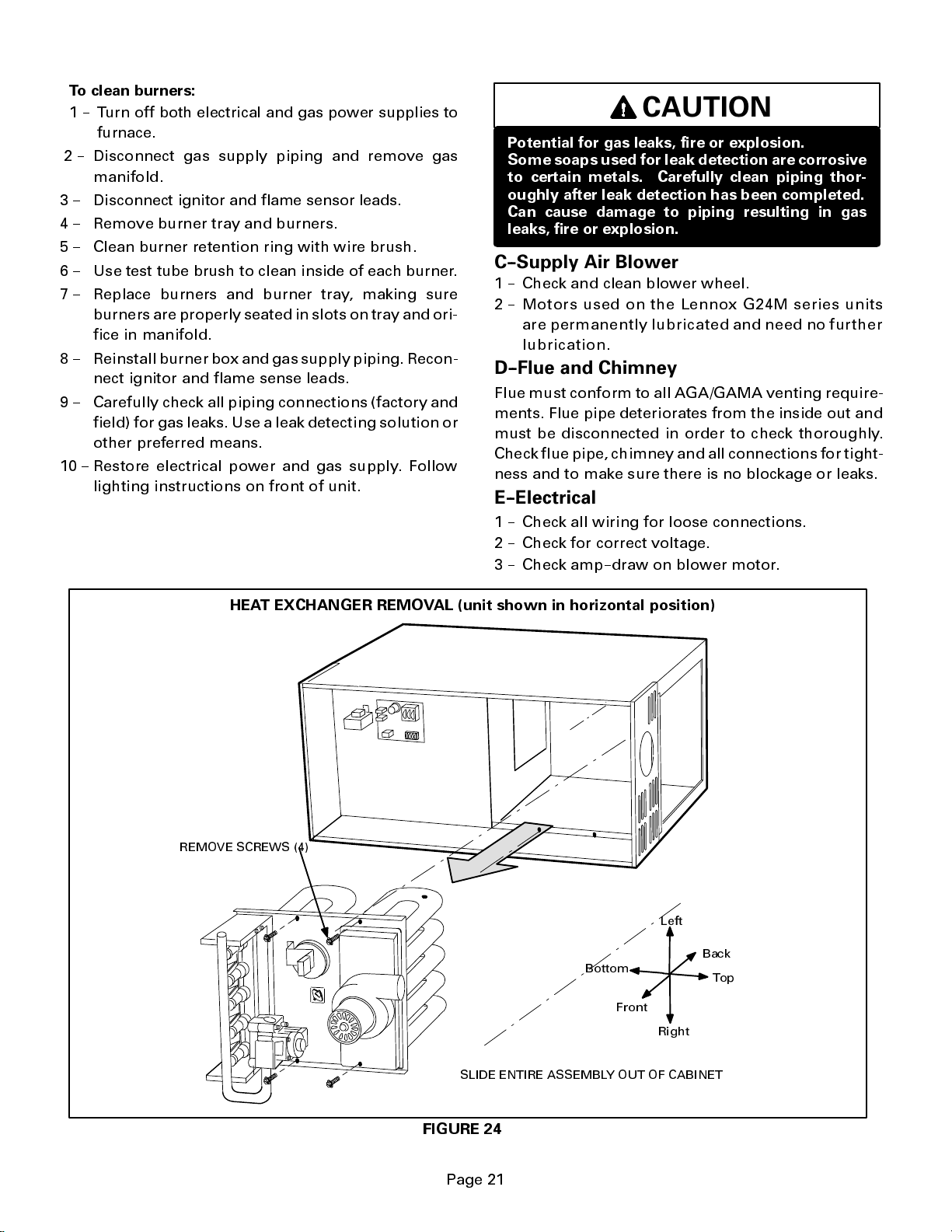
To clean burners:
1 -- Turn off both electrical and gas power supplies to
furnace.
2 -- Disconnect gas supply piping and remove gas
manifold.
3 -- Disconnect ignitor and flame sensor leads.
4 -- Remove burner tray and burners.
5 -- Clean burner retention ring with wire brush.
6 -- Use test tube brush to clean inside of each burner.
7 -- Replace burners and burner tray, making sure
burners are properly seated in slots on tray and ori-
fice in manifold.
8 -- Reinstall burner boxandgassupply piping. Recon-
nect ignitor and flame sense leads.
9 -- Carefully check all piping connections (factory and
field) for gas leaks. Use a leak detecting solution or
other preferred means.
10 -- Restore electrical power and gas supply. Follow
lighting instructions on front of unit.
CAUTION
Potential for gas leaks, fire or explosion.
Some soaps used for leak detection are corrosive
to certain metals. Carefully clean piping thor-
oughly after leak detection has been completed.
Can cause damage to piping resulting in gas
leaks, fire or explosion.
C--Supply Air Blower
1 -- Check and clean blower wheel.
2 -- Motors used on the Lennox G24M series units
are permane ntly lubricate d and need no further
lubrication.
D--Flue and Chimney
Flue must conform to all AGA/GAMA venting require-
ments. Flue pipe deteriorates from the inside out and
must be disconnected in order to check thoroughly.
Check flue pipe, chimney and all connections for tight-
ness and to make sure there is no blockage or leaks.
E--Electrical
1 -- Check all wiring for loose connections.
2 -- Check for correct voltage.
3 -- Check amp--draw on blower motor.
HEAT EXCHANGER REMOVAL (unit shown in horizontal position)
REMOVE SCREWS (4)
Bottom
Front
Left
Back
Top
Right
SLIDE ENTIRE ASSEMBLY OUT OF CABINET
FIGURE 24
Page 21
Page 22

VII--WIRING, OPERATION SEQUENCE
&TROUBLESHOOTING
A--Field Wiring, Thermostat Connections
),(/' ,167$//(' &/$66 ,, 9
),(/' ,167$//(' /,1( 92/7$*(
7+(50267$7
72 &2035(6625
&217$&725
7<3,&$/ *0 ),(/' :,5,1* ',$*5$0
&20%867,21
35(6685( 6:,7&+
*:5<
)/$0( 52//287 6:,7&+(6
35,0$5< /,0,7
75$16)250(5
*:<&5
685(/,*+7 &21752/
$,5 %/2:(5
*$6
9$/9(
6(&21'$5<
/,0,76
'225
,17(5/2&.
6:,7&+
)851,6+(' %< ,167$//(5
%/$&.
:+,7(
/ 1
*1'
),*85(
W
G24M and CONDENSING UNIT
THERMOSTAT DESIGNATIONS
(Refer to specific thermostat and outdoor unit.)
G24M
Condensing UnitThermostat
Furnace
HS UNIT
Y
COOLING
COMPRESSOR
Y
COMPRESSOR
INDOOR BLOWER
G
G
HEAT
W
POWER
R
COMMON
C
R
C
COMMON
HS UNIT
COMMON
),*85(
3DJH
Page 23

B--Early Model G24M Series With Ram Ignition Control
1--W
hen disconnect is closed, 120V is routedthrough
door interlock switch (S51) to feed the line voltage
side of the furnace control (A3)andtransformerT1
primary. Door interlock switch must be closed for
A3 and T1 to receive voltage.
2 -- T1 supplies 24VAC to terminal 24VAC on A3. In
turn, terminal R of A3 supplies 24VAC to termi-
nal RC of the indoor thermostat (not shown).
3 -- When there is a call for heat, W1 of the thermostat
energizes W of the furnace control with 24VAC.
4 -- CMB BLWR of the blower control energizes the
combustion air blower (B6).Whenthe combustion
air blower nears full speed, combustion air prove
switch (S18) closes.
5 -- When S18 closes, assuming the flame rollout
switch (S47), primary limit (S10) and secondary
limits (S21) are closed, the furnace control begins
a 45 second time-delay (pre-purge).
6 -- At the end of the pre-purge cycle, the furnace con-
trol simultaneously opens the gas valve andsends
high voltage to the spark electrode.
7 -- When flame is sensed, the furnace control begins
a 45 second delay before energizing the indoor
blower.
8 -- When heat demand is satisfied, W1 of the thermo-
stat de-energizes W of the furnace control and the
furnace control immediately de-energizes the gas
valve. The combustion air blower runs for 5 se-
conds (post-purge) before being de-energized.
Also, the indoor blower runs for a designated peri-
od (90--240 seconds) as set by switches on furnace
control.
3DJH
Page 24

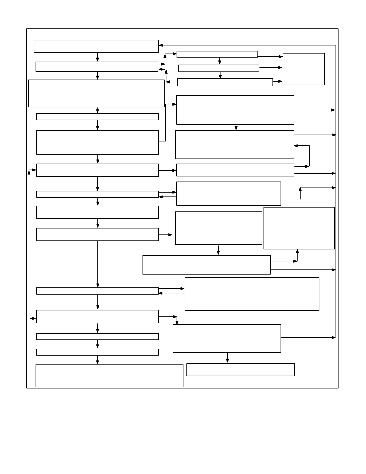
C--Ram Ignition Control Troubleshooting Guide
RAM CONTROL
HEATING TROUBLE SHOOTING SEQUENCE
NORMAL HEATING MODE ABNORMAL HEATING MODE
LED: SLOW FLASH RATE
THERMOSTAT CALLS FOR HEAT
LED: FAST FLASH RATE
FLAME OFF?
YES
CONTROL SELF--CHECK OKAY?
YES
HI LIMIT SWITCH CLOSED?
YES
PRESSURE SWITCH OPEN?
YES
COMBUSTION AIR BLOWER ON?
PRESSURE SWITCH CLOSED?
YES
PREPURGE (45 seconds)
IGNITION TRIAL (7 seconds) ---- START IGNITION
SPARK, OPEN MAIN GAS VALVE. INCREMENT
TRIAL REGISTER. HAS FLAME BEEN REGISTERED
WITHIN 7 SECONDS?
YES
SYSTEM FAN ON.
(Fixed 45--second delay)
NO
NO
NO
NO
NO
NO
LOCKOUT: MAIN VALVE OFF
COMB. AIR AND SYSTEM FANS ON
RESET THERMOSTAT
LED: 5 flash if flame sensed with valve off
LED: Steady on if control board failure
CHECK TO SEE IF MAIN VALVE IS OFF.
SEQUENCE HOLDS UNTIL HI LIMIT CLOSES.
LED: 4 flashes.
CHECK TO SEE IF MAIN VALVE IS OFF.
SEQUENCE HOLDS UNTIL PRES. SWITCH OPENS.
LED: 3 flashes.
CHECK TO SEE IF MAIN VALVE IS OFF.
SEQUENCE HOLDS UNTIL PRES. SWITCH CLOSES.
LED: Fast flash rate.
MAIN VALVE AND SPARK ARE OFF.
INCREMENT TRIAL REGISTER
THREE TRIALS COMPLETED?
YES
IGNITION RESET PERIOD
COMBUSTION & SYSTEM FANS OFF.
IS 60 MIN. RESET PERIOD COMPLETE?
LED: Fast flash rate.
NO
YES
FLAME SENSE OKAY?
YES
FLAME CONTINUOUSLY CHECKED?
ROLLOUT SWITCHES CLOSED
YES
HI LIMIT SWITCH CLOSED?
YES
PRESSURE SWITCH CLOSED?
YES
THERMOSTAT OPENS
LED: SLOW FLASH RATE
COMB. AIR BLOWER OFF (5 sec. delay)
FAN OFF (After selected 90, 120,
180, or 240 delay)?
NO
NO
NO
NO
MAIN VALVE AND SPARK OFF.
NO
START IGNITION SPARK (IN 0.8 SEC. MAXIMUM).
HAS FLAME BEEN DETECTED WITHIN 7 SEC.?
YES
LOCKOUT. MAIN VALVE OFF.
COMBUSTION AND SYSTEM FANS ON.
RESET OR REPLACE ROLLOUT SWITCH.
LED: 4 flashes.
MAIN VALVE OFF. COMBUSTION & SYSTEM FANS ON.
SEQUENCE HOLDS UNTIL SWITCH CLOSES.
LED: 4 flashes for hi limit.
LED: 3 flashes for pressure switch.
SWITCH CLOSED
YES
COMBUSTION FAN ON. SYSTEM FAN OFF.
(AFTER DELAY TO OFF INTERVAL COMPLETED.)
LED: Fast flash rate.
3DJH
Page 25

RAM CONTROL
COOLING TROUBLE SHOOTING SEQUENCE
REMAINS UNCHANGED THROUGHOUT COOLING CYCLE.
THERMOSTAT CALLS FOR COOLING.
COMPRESSOR CONTACTOR AND SYSTEM FAN
ENERGIZED AT COOLING SPEED AFTER
1 SECOND DELAY. ACC TERMINAL ENERGIZED.
SYSTEM FAN AND ACC TERMINAL OFF AFTER
COMPLETING SELECTED DELAY INTERVAL
LED: Slow flash rate.
THERMOSTAT OPENS.
COMPRESSOR OFF.
(At dip switches).
MANUAL FAN TROUBLESHOOTING SEQUENCE
REMAINS UNCHANGED THROUGHOUT SEQUENCE.
MANUAL FAN SELECTION MADE AT THERMOSTAT.
CONTROL ENERGIZES SYSTEM FAN AT CONTINUOUS
THERMOSTAT CALLS FOR COOLING.
YES NO
SYSTEM FAN SWITCHED TO COOLING
SPEED. ACC TERMINAL REMAINS ENERGIZED.
THERMOSTAT OPENS.
SYSTEM FAN SWITCHES TO CONTINUOUS SPEED
AND ENERGIZES ACC TERMINAL. BOTH REMAIN ON
UNTIL MANUAL FAN IS SWITCHED OFF AT THERMOSTAT.
SLOW FLASH
FAST FLASH
2 FLASH
3 FLASH
4 FLASH
5 FLASH
STEADY ON
NORMAL OPERATION. NO CALL FOR HEAT.
NORMAL OPERATION. CALL FOR HEAT.
SYSTEM LOCKOUT. FAILURE TO DETECT OR SUSTAIN FLAME.
.
PRESSURE SWITCH OPEN OR CLOSED.
HIGH LIMIT OR ROLLOUT SWITCH OPEN.
FLAME SENSED AND GAS VALVE NOT ENERGIZED.
CONTROL BOARD FAILURE.
LED: Slow flash rate.
SPEED. ACC TERMINAL ENERGIZED.
THERMOSTAT CALLS FOR HEAT.
NO
LED CODES
YES
SYSTEM FAN SWITCHES TO HEATING SPEED AFTER
SELECTED DELAY. ACC TERM. REMAINS ENERGIZED.
THERMOSTAT OPENS.
SYSTEM FAN SWITCHED OFF AFTER DELAY.
ACC TERMINAL DE--ENERGIZED.
3DJH
Page 26

D-Late Model G24M Series With SureLight Ignition Control
TYPICAL G24M DIAGRAM
(-11 MODEL SHOWN)
1 - When there is a call for heat, W1 of the thermostat ener-
gizes W of the furnace control with 24VAC.
2 - S10 primary limit switch and S47 rollout switch are closed.
Call for heat can continue.
3 - SureLight control energizes combustion air blower B6.
Combustionairblower runs until S18 combustion air prove
switch closes (switch must close within 2-1/2 minutes or
control goes into 5 minute Watchguard Pressure Switch
delay). Once S18 closes, a 15-second pre-purge follows.
4 - SureLight control energizes ignitor. A 20-second warm-up
period begins.
5 - Gas valve opens for a 4-second trial for ignition. Ignitor
staysenergizedthefirstsecond of trial. (Board 97L48 only:
ignitor energized during trial or until flame is sensed.
6 - Flame is sensed, gas valve remains open for the heat call.
7 - After 45-second delay, SureLight control energizes indoor
blower B3.
8 - Whenheatdemandissatisfied,W1oftheindoorthermostat
de-energizes W of the SureLight control which de-ener-
gizes the gas valve. Combustion air blowerB6 continues a
5-second post-purge period, and indoor blower B3 com-
pletes a selected OFF time delay.
Page 26
Page 27

SURELIGHT CONTROL HEATING
SEQUENCE OF OPERATION
NORMAL HEATING MODE ABNORMAL HEATING MODE
COMBUSTION AIR BLOWER ON FOR 1 SECOND.
SIGNAL IMPROPER
GROUND AT LED.
SIGNAL HOLDS
UNTIL UNIT IS
PROPERLY
GROUNDED.
IS COMBUSTION AIR BLOWER ENERGIZED?
(HTG ACC TERMINAL IS ENERGIZED WITH C.A.B.)
15-SECOND COMBUSTION AIR BLOWER PREPURGE
INITIATED BY CLOSED PRESSURE SWITCH.
POWER ON
CONTROL SELF--CHECK OKAY?
TURN INDUCER ON FOR 1 SECOND.
IS POLARITY REVERSED?
NO
NO
ROLLOUT SWITCH CLOSED?
(CONTINUOUS FLAME CHECK)
THERMOSTAT CALLS FOR HEAT:
PRESSURE SWITCH OPEN?
HAS COMBUSTION AIR PRESSURE
SWITCH CLOSED IN 2.5 MINUTES?
IS THERE
PROPER GROUND?
YES
BURNER OFF?
YES
NORMAL OPERATION:
LED #1 ---- SLOW FLASH
LED #2 ---- SLOW FLASH
LED #1 ---- FAST FLASH
LED #2 ---- FAST FLASH
YES
IS COMBUSTION AIR
YES
YES
YES
YES
CONTINUED NEXT PAGE
YES
YES
NO
YES
IS VOLTAGE
ABOVE 75 VOLTS?
NO
NO
NO
NO
GAS VALVE OFF. COMBUSTION AIR BLOWER ON.
GAS VALVE OFF. COMBUSTION AIR BLOWER OFF.
(RESET CONTROL BY TURNING MAIN POWER OFF.)
NO
GAS VALVE OFF. COMBUSTION AIR BLOWER OFF.
INDOOR BLOWER OFF WITH DELAY.
LED #1 ---- ON. LED #2 ---- SLOW FLASH.
SEQUENCE HOLDS UNTIL ROLLOUT SWITCH CLOSES.
GAS VALVE OFF. COMBUSTION AIR BLOWER ON.
INDOOR BLOWER ON HEATING SPEED.
PRESSURE SWITCH IS IN WATCHGUARD MODE.
GAS VALVE OFF. COMBUSTION AIR BLOWER OFF.
INDOOR BLOWER OFF WITH DELAY.
LED #1 ---- OFF. LED #2 ---- SLOW FLASH.
IS 5-MINUTE RESET PERIOD COMPLETE?
INDOOR BLOWER ON.
LED #1 ALTERNATING FAST FLASH
LED#2 ALTERNATING FAST FLASH
CHECK FOR BROKEN IGNITOR OR
OPEN IGNITOR CIRCUIT
INDOOR BLOWER DELAY OFF.
LED #1 ON
LED #2 ON
POLARITY REVERSED.
LED #1 ---- FAST FLASH
LED #2 ---- SLOW FLASH
LOW VOLTAGE SIGNAL AT LED HOLDS
UNTIL VOLTAGE RISES ABOVE 75 VOLTS.
LED #1 ---- SLOW FLASH
LED #2 ---- OFF
GAS VALVE OFF.
COMBUSTION AIR BLOWER OFF.
INDOOR BLOWER OFF WITH DELAY.
LED #1 OFF
LED #2 SLOW FLASH
(Sequence holds until pressure switch
closes or thermostat resets control.)
3DJH
Page 28
NORMAL HEATING MODE ABNORMAL HEATING MODE
15-SECOND COMBUSTION AIR INDUCER PREPURGE
INITIATEDBY CLOSED PRESSURE SWITCH.
YES
IGNITOR WARM-UP -- 20 SECONDS.
YES
4-SECOND TRIAL FOR IGNITION. GAS VALVE OPENS.
IGNITOR ENERGIZED FOR 1 SECOND AFTER VALVE
OPENS. NO FLAME SENSED DURING THIS PERIOD.
BOARD 97L48: IGNITOR ENERGIZED DURING TRIAL OR
FLAME SIGNAL ABOVE 0.7 MICROAMPS?
UNTIL FLAME SENSED.
YES
FLAME STABILIZATION PERIOD.
4 SECONDS
FLAME RECTIFICATION CURRENT
CHECK. CAN FLAME BE PROVEN WITHIN
4 SECONDS AFTER GAS VALVE OPENS?
(>0.15 microamps)
YES
FLAME PRESENT?
YES
YES
INDOOR BLOWER ON DELAYBEGINS
(45 seconds.)
YES
PRIMARY AND SECONDARY LIMIT
SWITCHES CLOSED?
YES
(See table 2 DIAGNOSTIC CODES for limit reset operation)
IS VOLTAGE ABOVE 75 VOLTS?
NO
IS THERE A PROPER GROUND?
YES
IS IGNITOR INTACT AND CONNECTED?
GAS VALVE OFF. COMBUSTION AIR INDUCER ON.
NO
HAS CONTROL FAILED TO SENSE FLAME FOR
FIVE CONSECUTIVE TRIES DURING A SINGLE
IGNITION WATCHGUARD MODE. GAS VALVE OFF.
LED 1 ALT. SLOW FLASH LED 2 ALT SLOW FLASH
IS 60-MINUTE RESET PERIOD COMPLETE?
NO
NO
GAS VALVE DE-ENERGIZED.
COMBUSTION AIR INDUCER
DE-ENERGIZED.INDOOR BLOWER
NO
ON UNTIL SWITCH CLOSES.LED #1
-- SLOW FLASH. LED #2 -- ON.
IS LIMIT SWITCH CLOSED?
HAS PRIMARY/SECONDARY LIMIT RESET.
YES
YES
INDOOR BLOWER OFF.
HEATDEMAND?
COMBUSTION AIR INDUCER OFF.
INDOOR BLOWER OFF WITH DELAY
HAS CONTROL RESET IGNITION
SEQUENCE FOUR TIMES?
LOW FLAME SIGNAL
(Does not affect operation of control)
LED #1 -- SLOW FLASH
LED #2 -- FAST FLASH
YES
NO
NO
LIMIT SWITCH WATCHGUARD
MODE. GAS VALVE OFF.
COMB. AIR INDUCER OFF. INDOOR BLOWER OFF WITH
DELAY. LED#1-SLOW FLASH
LED#2- ON. IS 60MINUTE RESET PERIOD COMPLETE.?
LEDS SIGNAL
ALTERNATING
FAST FLASH
NO
NO
YES
NO
YES
YES
NO
YES
NO
ROLLOUT SWITCH CLOSED?
YES
COMBUSTION AIR PRESSURE
SWITCH CLOSED?
YES
THERMOSTAT DEMAND SATISFIED.
YES
LED #1 & #2 SIMULTANEOUS SLOW FLASHES.
YES
COMB. AIR INDUCER CONTINUES 5-SECOND POST PURGE
AFTER T’STAT DEMAND IS SATISFIED.INDOOR AIR BLOWER
COMPLETES SELECTED “OFF” DELAYBEFORE SHUTTING OFF.
ACB.HEATSPEED, HTG ACC TERM. AND ACC TERM. OFF.
NO
HAS CAB SWITCH CLOSED IN 2.5 MINUTES?
COMBUSTION AIR INDUCER POWER OFF.
SEQUENCE HOLDS UNTIL ROLLOUT SWITCH IS RESET
GAS VALVE DE-ENERGIZED.
COMBUSTION AIR INDUCER ON.
INDOOR BLOWER OFF WITH DELAY
LED #1 -- OFF. LED #2 -- SLOW FLASH.
5-MINUTE PRESSURE SWITCH
GAS VALVE POWER OFF.
INDOOR BLOWER OFF WITH DELAY
LED #1 -- ON. LED #2 -- SLOW FLASH.
YES
NO
WATCHGUARD MODE.
YES
Page 28
Page 29

SURELIGHT CONTROL COOLING SEQUENCE
NORMAL COOLING MODE ABNORMAL COOLING MODE
POWER ON
IGNITION CONTROL MAIN POWER ON.
SIGNAL IMPROPER
GROUND AT LED.
SIGNAL HOLDS
UNTIL UNIT IS
PROPERLY
GROUNDED.
ROLLOUT SWITCH MONITORED CONTINUOUSLY.
CHECK FOR MAIN BURNER FLAME SENSE.
LED: SLOW FLASH RATE REMAINS UNCHANGED
CONTROL SELF DIAGNOSTIC CHECK.
IS CONTROL OPERATING NORMALLY?
YES
TURN INDUCER ON FOR 1 SECOND.
IS POLARITY REVERSED?
NO
NO
IS ROLLOUT SWITCH CLOSED?
IS MAIN BURNER FLAME OFF?
THROUGHOUT COOLING CYCLE.
THERMOSTAT CALLS FOR COOLING.
IS THERE
PROPER GROUND?
YES
YES
NO
YES
IS VOLTAGE
ABOVE 75 VOLTS?
NO
NO
GAS VALVE OFF. COMBUSTION AIR BLOWER OFF.
INDOOR BLOWER OFF WITH NORMAL DELAY.
SIGNAL CIRCUIT BOARD FAILURE AT LED.
INTERRUPT MAIN POWER TO RESET CONTROL.
SIGNAL POLARITY REVERSED AT LED.
NO
GAS VALVE OFF. COMBUSTION AIR BLOWER OFF.
INDOOR BLOWER OFF WITH NORMAL DELAY.
SIGNAL CIRCUIT BOARD FAILURE AT LED.
SEQUENCE HOLDS UNTIL ROLLOUT SWITCH CLOSES.
GAS VALVE OFF. COMBUSTION AIR BLOWER OFF.
INDOOR BLOWER OFF WITH NORMAL DELAY.
SIGNAL CIRCUIT BOARD FAILURE AT LED.
SEQUENCE HOLDS UNTIL FLAME IS NOT SENSED.
LOW VOLTAGE SIGNAL AT LET HOLDS
UNTIL VOLTAGE RISES ABOVE 75 VOLTS.
COMPRESSOR CONTACTOR AND SYSTEM FAN
ENERGIZED WITH 0-SECOND DELAY
ACB COOL SPEED AND ACC. TERM. ENERGIZED.
THERMOSTAT OPENS.
COMPRESSOR OFF.
ACB COOL SPEED AND ACC. TERM. OFF
WITH 0-SECOND DELAY.
3DJH
Page 30

CONTINUOUS LOW SPEED FAN SEQUENCE OF OPERATION
LED: SLOW FLASH RATEREMAINS
UNCHANGED THROUGHOUT SEQUENCE.
MANUAL FAN SELECTION MADE ATTHERMOSTAT.
CONTROL (G) ENERGIZES SYSTEM FAN AT ACB
LOW SPEED. ACC. TERMINAL IS ENERGIZED.
THERMOSTAT CALLS FOR HEAT (W).
NO YES
THERMOSTAT CALLS FOR COOLING.
YES
SYSTEM FAN SWITCHED TO ACB COOL
SPEED. ACC. TERM. REMAINS ON.
THERMOSTAT OPENS.
NO
HTG ACC. TERM. ENERGIZES
WITH COMB. AIR BLOWER.
BOARD NO. 63K8901
SYSTEM FAN DE-ENERGIZED. SYSTEM FAN
ENERGIZES ON ACB HEATSPEED AFTER
NORMAL DELAY.
BOARD NO. 24L85, 56L83, 97L48
SYSTEM FAN SWITCHES TO ACB HEAT SPEED
AFTER NORMAL DELAY (fan remains energized)
THERMOSTAT OPENS. COMBUSTION AIR
AND HTG ACC TERMINAL DE-ENERGIZE.
BOARD 63K89: SYSTEM FAN OFF. ACC. TERM.
OFF. (AFTER OFF DELAY COMPLETED).
BOARDS 24L85, 56L83 AND 97L48:
SYSTEM FAN SWITCHES TO
LOW SPEED AFTER NORMAL DELAY.
(fan remains energized)
MANUAL FAN SELECTION MADE ATTHERMOSTAT.
CONTROL (G) ENERGIZES SYSTEM FAN AT ACB
LOW SPEED. ACC. TERM. ENERGIZED.
Page 30
Page 31

E--SureLight Ignition Control Troubleshooting Guide
out code
LED#2 Slow Flash
ACTION 1
Check wiring connections to
blowerdoesnot energize
blower does not energize
versed
120V field connection.
UPON INITIAL POWER UP, REMOVE ALL THERMOSTAT DEMANDS TO THE UNIT
PROBLEM: 1 UNIT FAILS TO OPERATE IN THE COOLING, HEATING, OR CONTINUOUS FAN MODE
Condition Possible Cause Corrective Action / Comments
1.1
--
Both diagnostic lights fail to light
up.
LED#1--Off
LED#2--Off
1.2
--
Diagnostic lights flash the roll--
out code.
.
LED#1--On,
LED#2--Slow Flash
1.3
-- On initial power--up the comb. air
.
.
-- Diagnostic lights flash the re-
verse polarity code.
Main voltage 120V not supplied to
unit.
Miswiring of furnace or improper
connections.
Circuit breaker tripped or fails to
close.
Door interlock switch failure.
Transformer Failure.
Failed control board.
Roll--out switch open.
Roll--out switch failure.
Miswiring or improper connections
at roll--out switch.
Nine pin connector failure
120V main power polarity re-
versed.
.
1.1.1
1.1.2
1.1.3
1.1.4
1.1.5
1.1.6
1.2.1
1.2.2
1.2.3
1.2.4
1.3.1
ACTION 1 --
Determine cause of main power failure.
ACTION 1 --
to power make up box and transformer.
ACTION 2
board.
ACTION 1 --
set but does not have continuity.
ACTION 2 --
for short.
ACTION 1--
when door is closed.
ACTION 2 --
replace loose connectors.
ACTION 3 --
closed position. Replace if malfunctioning
ACTION 1 --
24V. Replace if malfunctioning
ACTION 1 --
checked, replace board.
ACTION 1 --
switch by pushing the top button.
ACTION 2 --
out switch activation before leaving furnace.
ACTION 1 --
switch. Replace roll--out switch if switch is
reset but does not have continuity.
ACTION 1 --
switch.
ACTION 1 --
er connection to control board.
ACTION 2 --
plug pin.
ACTION 1 --
tral correctly input into control.
ACTION 2 --
120V field connection.
Check 120V main voltage.
Check for correct wiring of 120V
-- Check 24V wiring to control
Replace circuit breaker if it is re-
If circuit breaker still trips, check
Check thatdoor switch is activated
Check wire connections to switch,
Check continuity of switch in
Check that transformer output is
If all the above items have been
Manually reset the roll--out
Determine the cause of the roll--
Check continuity across roll--out
Check wiring connections to
Check 9--pin connector for prop-
Check continuity of the multi
Check the 120V has line and neu-
Reverse the line and neutral at the
LED#1--Fast Flash,
LED#2--Slow Flash.
-- On initial power up the combus-
tion air blower does not energize.
-- Diagnostic lights flash normal
power on operation.
LED#1--Slow Flash
LED#2--Slow Flash
1.4
1.4.1
Open combustion air blower motor
circuit.
1.4.2
Failed combustion air blower mo-
tor.
3DJH
ACTION 1 --
blower. If no power, check wire and connec-
tions.
ACTION 1 --
place blower.
Check for 120V to combustion air
If power is present at blower, re-
Page 32

PROBLEM 1: UNIT FAILS TO OPERATE IN THE COOLING, HEATING, OR CONTINUOUS FAN MODE
g
fail
Condition Possible Cause Corrective Action / Comments
1.5
--
On initial power--up the combus-
tion air blower remains energized.
--
Diagnostic lights flash the im-
proper main ground.
LED#1--Alternating Fast Flash
LED#2--Alternating Fast Flash
1.5.1
Improper ground to the unit.
1.5.2
6--Pin connector is improperly at-
tached to the circuit board.
1.5.3
Line voltage is below 75V.
ACTION 1 --
ground.
ACTION 2 --
the unit
ACTION 1--
installation. Correctly insert connector into
control.
ACTION 1 --
above 75V. Determine cause of voltage drop
and supply correct voltage to the control.
Check that the unit is properly
Install a proper main ground to
Check 6--pin connectorfor proper
Check that the line voltage is
PROBLEM 2: UNIT OPERATES IN COOLING MODE BUT NOT IN THE HEATING MODE, WITH
COMBUSTION AIR BLOWER CYCLING 5 SECONDS ON 55 SECONDS OFF.
Condition Possible Cause Corrective Action / Comments
2.1
--
On initial power--up the combus-
tion air blower remains energized.
--
Diagnostic lights flash the im
proper main ground.
--Combustion airblower cycles 5
seconds on 55 seconds off.
LED#1--Alternating Fast Flash
LED#2--Alternating Fast Flash
2.1.1
Open ignitor circuit.
2.1.2
Broken or failed ignitor.
ACTION 1 --
loose connectionsin theignitor circuit. Check
mult--plug connections for correct installa-
tion.
ACTION 1 --
tance across ignitor. If resistance does not
read between 10.9and 19.7ohms, replacethe
ignitor.
Check for correct wiring and
Unplug ignitor and read resis-
PROBLEM 3: UNIT FAILS TO FIRE IN THE HEATING MODE, COMBUSTION AIR BLOWER DOES
NOT ENERGIZE
Condition Possible Cause Corrective Action / Comments
3.1
--
Unit operates with a cooling or
continuous fan demand.
--
Combustion air blower will not
start with a Heating demand.
-- Diagnostic lights flash the limit
ure mode.
LED#1--Slow Flash,
LED#2--On
3.2
-- Unit operates with a cooling and
continuous fan demand.
-- Combustion air blower will not
start with a Heating demand.
--
Diagnostic lights flash the pres-
sure switch failure code.
LED#1--Off,
LED#2--Slow Flash
3.1.1
Primary or secondary (if equipped)
limit open.
3.1.2
Miswiring of furnace or improper
connections at limit switch(es).
3.2.1
Miswiring of furnace or improper
connections to combustion air
blower.
3.2.2
Pressure switch stuck closed.
ACTION 1 --
switch(es). Switches reset automatically
upon cool down.
ACTION 2 --
inlet air (including filter) and outlet air. Deter-
mine causefor limit activation before placing
unit back in operation.
ACTION 1 --
loose connections. Correct wiring and/or re-
place any loose connections.
ACTION 1 --
loose connections. Correct wiring and/or re-
place any loose connections.
ACTION 1 --
open without the combustion air blower op-
erating. Replace if malfunctioning
Check continuity across
Check for restrictions on blower
Check for correct wiring and
Check for correct wiring and
Check that the pressure switch is
3DJH
Page 33

PROBLEM 3: UNIT FAILS TO FIRE IN THE HEATING MODE, COMBUSTION AIR BLOWER DOES
sure switch failure code 2.5 minutes
LED#2 Slow Flash
-- Unit operates with a cooling and
continuous fan demand.
--
Combustion air blower will not
start with a Heating demand.
--
Diagnostic lights flash the pres-
sure switch failure code 2.5 minutes
after heating demand.
LED#1--Off,
LED#2--Slow Flash
PROBLEM 4: UNIT FAILS TO FIRE IN THE HEATING MODE, COMBUSTION AIR BLOWER
--
Unit operates with a cooling and
continuous fan demand.
--
Combustion air blower ener-
gizes with a heating demand.
-- Diagnostic lights flash the pres-
sure switch failure code 2.5 min-
utes after heating demand.
LED#1--Off
LED#2--Slow Flash
NOT ENERGIZE (CONT.).
Condition Possible Cause Corrective Action/Comments
3.3
3.3.1
Miswiring of furnace or improper
connections to combustion air
ACTION 1 --
loose connections. Correct wiring and/or re-
place any loose connections.
Check for correct wiring and
blower.
3.3.2
Combustion air blower failure.
ACTION 1 --
blower and it does not operate, replace com-
bustion air blower.
If there is 120V to combustion air
ENERGIZES, IGNITOR IS NOT ENERGIZED.
Condition Possible Cause Corrective Action/Comments
4.1
Pressure switch does not close
due to incorrect routing of the
pressure switch lines.
Pressure switch does not close
due to obstructions in the pressure
Pressure switch lines damaged
Pressure switch does not close
due to a low differential pressure
across the pressure switch.
Wrong pressure switch installed in
the unit, or pressure switch is out
Miswiring of furnace or improper
connections at pressure switch.
Pressure switch failure.
4.1.1
4.1.2
lines.
4.1.3
4.1.4
4.1.5
of calibration.
4.1.6
4.1.7
ACTION 1 --
lines are correctly routed. Correctly route
pressure switch lines.
ACTION 1 --
the the pressure lines and/or taps.
ACTION 1 --
leaks. Replace any broken lines.
ACTION 1 --
across the pressure switch. This pressure
should exceed the set point listed on the
switch.
ACTION 2 --
exhaust vent. Remove all blockage.
ACTION 3 --
and run length. See installation instruc-
tions.
ACTION 4 --
tion air blower.
ACTION 1 --
switch is installed in the unit. Replace pres-
sure switch if necessary.
ACTION 1 --
loose connections. Correct wiring and/or re-
place any loose connections.
ACTION 1 --
have been checked, the pressure switch may
have failed. Replace pressure switch and de-
termine if unit will operate.
Check that the pressure switch
Remove any obstructions from
Check pressure switch lines for
Check the differential pressure
Check for restricted inlet and
Check for proper vent sizing
Check voltage to thre combus-
Check that the proper pressure
Check for correct wiring and
If all the above modes of failure
3DJH
Page 34

PROBLEM 5: UNIT FAILS TO FIRE IN THE HEATING MODE, COMBUSTION AIR BLOWER
failed to ignite code.
ENERGIZES, IGNITOR IS ENERGIZED. (CONT.)
Condition Possible Cause Corrective Action/Comments
5.1
-- Unit operates with a cooling and
continuous fan demand.
--Combustion airblower ener-
gizes with Heating demand.
--
Ignitor is energized but unit fails
to light.
LED#1--Alternating Slow Flash
LED#2--Alternating Slow Flash
5.1.1
Check that gas is being supplied to
the unit.
5.1.2
Miswiring of gas valve or loose
connections at multi--pin control
amp plugs or valve.
5.1.3
Malfunctioning gas valve or igni-
tion control.
ACTION 1 --
valve.Pressure should not exceed 13WC for
both natural and propane. Line pressure
should read a minimum 4.5 WC for natural
and 8.0WC for propane.
ACTION 1 --
loose connections. Correct wiring and/or re-
place any loose connections.
ACTION 1 --
gas valve approximately 35 seconds after
heat demand is initiated.
ACTION 2 --
plied but valve does not open (check for ex-
cessive gas line pressure before replacing
gas valve).
ACTION 3 --
is not supplied to valve.
Check line pressure at the gas
Check for correct wiring and
Check that 24V is supplied to the
Replace the valve if 24V is sup-
Replace the control board if 24V
PROBLEM 6: BURNERS LIGHT WITH A HEATING DEMAND BUT UNIT SHUTS DOWN
PREMATURELY
Condition Possible Cause Corrective Action/Comments
6.1
-- Burners fire with a heating de-
mand.
-- Burners light but unit shuts off
prior to satisfying T--stat demand.
-- Diagnostic lights flash the pres-
sure switch code.
6.1.1
Low pressure differential at the
pressure switch.
ACTION 1 --
exhaust. Remove all blockage.
ACTION 2:
installation instructions.
Check for restricted vent inlet or
Check for proper vent sizing. See
LED#1--Off
LED#2--Slow Flash
-- Combustion air blower energizes
with a heating demand.
-- Burners light but fail to stay lit.
-- After 5 tries the control diagnos-
tics flash the watchguard burners
failed to ignite code.
LED#1--Alternating Slow Flash
LED#2--Alternating Slow Flash
6.2
6.2.1
Sensor or sense wire is improperly
installed.
6.2.2
Sensor or sense wire is broken.
6.2.3
Sensor or sensor wire is grounded
to the unit.
6.2.4
Control does not sense flame.
ACTION 1 --
located (page 10) and that the sense wire is
properly attached to both the sensor and
the control.
ACTION 1 --
ACTION 2 --
wire. If wire or sensor are damaged replace
the component.
ACTION 1 --
the sensor rod and the unit ground.
ACTION 2 --
the sensor wire and the unit ground.
ACTION 3 --
cuit.
ACTION 1 --
from the burner flame. If the microamp sig-
nal is below 0.70 microamps, check the
sense rod for proper location or contamina-
tion.
ACTION 2 --
flame sense rod. If rod is to be cleaned, use
steel wool or replace sensor. DO NOT
CLEAN ROD WITH SAND PAPER. SAND PA-
PER WILL CONTRIBUTE TO THE CONTAMI-
NATION PROBLEM.
to bend sense rod.
Check that sensor is properly
Check for a broken sensor.
Test continuity across the sense
Check for resistance between
Check for resistance between
Correct any shorts found in cir-
Check the microamp signal
Replace, clean, or relocate
Do not attempt
NOTE:
3DJH
Page 35

PROBLEM 6: BURNERS LIGHT WITH HEATING DEMAND BUT UNIT SHUTS DOWN
g
guard flame failure
Condition Possible Cause Corrective Action/Comments
6.3
-- Combustion air blower ener-
gizes with a heating demand.
-- Burners light.
-- Roll--out switch trips during the
heating demand.
-- Diagnostic lights flash roll--out
failure.
LED#1--On
LED#2--Slow Flash
6.4
--
Combustion air blower ener-
gizes with a heating demand.
-- Burners light roughly and the
unit fails to stay lit.
-- Diagnostic lights flash watch-
uard flame failure.
.
PREMATURELY (CONT.)
6.3.1
Unit is firing above 100% of the
nameplate input.
6.3.2
Gas orifices leak at the manifold
connection.
6.3.3
Insufficient flow through the heat
exchanger caused by a sooted or
restricted heat exchanger.
6.3.4
Burners are not properly located in
the burner box.
6.4.1
Recirculation of flue gases. This
condition causes rough ignitions
and operation. Problem is charac-
terized by nuisance flame failures.
ACTION 1 --
matches value listed on nameplate. See
installation instructions for proper proce-
dure.
ACTION 2 --
size match the size listed on the nameplate or
installation instructions.
ACTION 3 --
insure no leaks are present.
ACTION 4 --
matches value listed on nameplate.
ACTION 1 --
NOTE:
ACTION 2 --
threaded orifice connection. Use approved
method for leak detection (see unit instruc-
tions).
ACTION 1 --
er restrictions in the heat exchanger assem-
bly.Clean assembly as outlined in instruction
manual.
ACTION 2--
proper combustion and flow. CO2 should
measure between 6.0% and 8.0% for NG and
between 6.5% and 8.5% for LP. CO should
measure below .04% (400PPM) in an air--free
sample of flue gases for either NG or LP.
ACTION 1 --
into the center of the heat exchanger open-
ings. Correct the location of the burners if
necessary.
ACTION 1 --
gases away from intake vent. Remove any
obstacles in front of the intake and exhaust
vent which would cause recirculation.
ACTION 2 --
haust vent installation. See instructions
Check that the manifold pressure
Verify that the installed orifice
Check gas valve sensing hose to
Check the input rate to verify rate
Tightenorifice untilleak issealed.
Be careful not to strip orifice threads.
Check for gas leakage at the
Checkfor sooting deposits or oth-
For G24Mgas furnaces, check for
Check that the burners are firing
Check for proper flow of exhaust
Check for correct intake and ex-
LED#1--Alternating Slow Flash
LED#2--Alternating Slow Flash
6.4.2
Improper burner cross--overs
3DJH
ACTION 1 --
cross--overs for burrs, or any restriction or if
crossover is warped. Remove restriction or
replace burners.
Remove burner and inspect the
Page 36

PROBLEM 6: BURNERS LIGHT WITH HEATING DEMAND BUT UNIT SHUTS DOWN
sense code
6.5
-- Combustion air blower ener-
gizes with a heating demand.
-- Burners light.
-- Diagnostic lights flash watch
guard flame failure.
-- NOTE Unit might go into 60
minute Watchguard mode depend-
ing on intermittent nature of sen-
sor signal.
LED#1--Alternating Slow Flash
LED#2--Alternating Slow Flash
PROBLEM 7: CONTROL SIGNALS LOW FLAME SENSE DURING HEATING MODE
Condition Possible Cause Corrective Action/Comments
7.0
-- Unit operates correctly but the
diagnostic lights flash low flame
.
LED#1--Slow Flash
LED#2--Fast Flash
PREMATURELY (CONT.)
6.5.1
Loose sensor wire connection
causes intermittent loss of flame
signal.
7.1.1
Sense rod is improperly located on
the burner.
7.1.2
Sense rod is contaminated.
ACTION 1 --
located.
ACTION 2 --
erly attached to both the sensor and the con-
trol. Pay extra attentionto thepin connectors.
ACTION 1 --
location on the burner. Properly locate the
sense rod or replace if rod cannot be located
correctly.
ACTION 1 --
tion or coated surface. Clean the sense rod
with steel wool or replace sensor. DO NOT
USE SAND PAPER TO CLEAN ROD. SAND
PAPER WILL CONTRIBUTE TO THE CON-
TAMINATION PROBLEM.
Check that the sensor is properly
Check that the sense wire isprop-
Check the sense rod for proper
Check sense rod for contamina-
PROBLEM 8: INDOOR BLOWER FAILS TO OPERATE IN COOLING, HEATING, OR CONTINUOUS
FAN MODE
Condition Possible Cause Corrective Action/Comments
8.0
-- Indoor blower fails to operate in
continuous fan, cooling, or heating
mode.
Miswiring of furnace or improper
connections at control or indoor
120V is not being supplied to the
indoor air blower or blower motor
Defective control board
8.1.1
blower motor.
8.1.2
failure.
8.1.3
ACTION 1--
loose connections. Check for correct wiring
and loose connections.
ACTION 1 --
calls for indoor blower by energizing Y,
G, and W individually on thelow voltage
terminal strip. Note that when W is ener-
gized, the blower is delayed 45 seconds. If
there is 120V to each motor tap but the blow-
er does not operate, replace the motor.
ACTION 1 --
G, orW is energized, replace the control.
Correct wiring and/or replaceany
Check for 120V at the various
If there is not 120V when Y,
PROBLEM 9: RF STATIC DURING TIME FOR IGNITION
Condition Possible Cause Corrective Action/Comments
9.0
-- AM radio interference.
9.1.2
Ignitor operation
ACTION 1 --
Call Technical Support, Dallas.
3DJH
 Loading...