

Page 1

PRODUCT LITERATURE
¤
1998 Lennox Industries Inc.
503,891M
9/98
Supersedes 503,299M
Dallas, Texas
£
G24E
SERIES
GAS FURNACE
0$.(5·6
This appliance complies
with the requirements of
THE AUSTRALIAN
GAS ASSOCIATION
:$55$17<
RETAIN THESE INSTRUCTIONS
FOR FUTURE REFERENCE
:$51,1*
Litho U.S.A.
If the information in this manual is not
followed exactly, a fire or explosion
may result causing property damage,
personal injury or loss of life.
Do not store or use gasoline or other
flammable vapors and liquids in the
vicinity of this or any otherappliance.
Installation and service must be performed by a qualified installer, service agency or the gas supplier.
WHAT TO DO IF YOU SMELL GAS:
Do not try to light any appliance.
Extinguish any open flames.
Do not touch any electrical switch; do not
use any phone in your building.
Immediately call your gas supplier from a
neighbor’s phone. Follow the gas supplier’s
instructions.
If you cannot reach your gas supplier, call
the fire department.
Page 1
Page 2
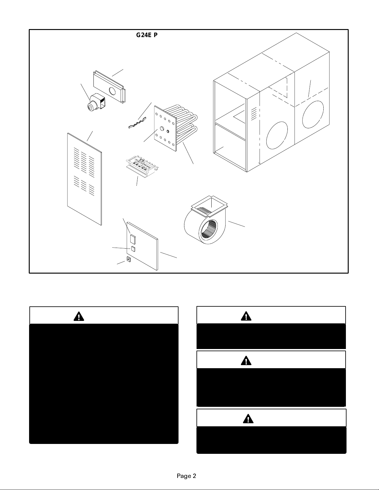
COMBUSTION AIR
BLOWER
FRONT LOUVERED
G24E PARTS IDENTIFICATION
FLUE BOX
COIL DECK
FLUE BAFFLES
(75 only)
PANEL
PRESSURE
SWITCH
HEAT EXCHANGER
ASSEMBLY
BURNER ASSEMBLY
CONTROL BOARD
TRANSFORMER
DOOR INTERLOCK SWITCH
WARNING
Product contains fiberglass wool.
Disturbing the insulation in this product during
installation, maintenance, or repair will expose
you to fiberglass wool. Breathing this may
causelungcancer.(Fiberglasswoolisknownto
the State of California to cause cancer.)
Fiberglass wool may also cause respiratory,
skin, and eye irritation.
To reduce exposure to this substance or for further information, consult material safety data
sheets available from address shown below, or
contact your supervisor.
Lennox Industries Inc.
P.O. Box 799900
Dallas, TX 75379-9900
BLOWER ASSEMBLY
BLOWER ACCESS
PANEL
WARNING
If overheating occurs or if gas supply fails to
shut off, shut offthemanualgasvalvetotheappliance before shutting off electrical supply.
WARNING
Do not use this furnace if any part has been
underwater.Immediatelycall a qualified service
technician to inspect the furnace and to replace
any part of the control system and any gas control which has been under water.
CAUTION
Before attempting to perform any service or
maintenance, turn the electrical power to unit
OFF at disconnect switch.
Page 2
Page 3

IMPORTANT
Any additions, changes, or conversions requiredinorderforthe appliance to satisfactorily
meet the application needs must be made by a
Lennox service technician using factory specified and approved parts.
IMPORTANT DIRECTIONS
1 - Keep the furnace area clear and free of combustible
material,gasoline,andotherflammablevaporsandliquids. If installed in an insulated area, furnace must be
kept free of insulating material. Insulating material may
be combustible. Inspect furnace venting system to
make sure it is in place, physically sound, and without
holes, corrosion, or blockage. Inspect furnace return
air duct connection to ensure duct is sealed to the furnace and terminates outside the space containing the
furnace. Inspect the physical support of the furnace to
guarantee that it is sound without sagging, cracks or
gaps around base and it maintains seal between base
and support.
2 - DO NOT obstruct air flow to unit. Unit must receive an
unobstructed flow of combustion and ventilating air.
3 - DO NOT store chlorine or fluorineproducts near unit or
introduce these products into the combustion air.
These products can cause furnace corrosion.
LIGHTING INFORMATION AND OPERATION
4 - This appliance Is equipped with an ignition device
which automatically lights the burner. Do
light the burner by hand.
5 - Remove control access panel.
6-
White Rodgers 36E Gas Valve -
valve 180qeither way to
OFF
Honeywell VR8205 Gas Valve -
valve clockwise
3.
THERMOSTATS
WHITE RODGERS 36E SERIES GAS VALVE
12
2))
OFF
to
FIGURE 1
Turn knob on gas
. See figure 2.
Turn knob on gas
. Do not force. Seefigure
not
try to
WARNING
If you do not follow these instructions exactly,a
fire or explosion may result causing property
damage, personal injury or loss of life.
BEFORE LIGHTING smell all around the appliance
area forgas.Be sure to smell nextto the floor because
some gas is heavier than air and will settle on the
floor.
Use only your hand to push in or turn the gas control
knob. Never usetools.Ifthe knob will not push in orturn
by hand, do not try to repair it, call a qualified service
technician. Force or attempted repairmayresultina fire
or explosion.
To place G24E furnace into operation:
G24E units are equipped with an electronic ignition sys-
tem. Do not
furnaces. Each time thermostat calls for heat, the burn-
er will automatically light.
Gas Valve Operation (Figures 2 and 3)
STOP
1-
of this section.
2 - Set thermostat to lowest setting. See figure 1.
3 - Turn off all electrical power to appliance.
attempt to manually light burners on these
! Read the safety information at the beginning
GAS VALVE SHOWN IN OFF POSITION
FIGURE 2
HONEYWELL VR8205SERIESGASVALVE
ON
OFF
GAS VALVE SHOWN IN OFF POSITION
FIGURE 3
7 - Wait five (5) minutes to clear out any gas. If you then
smell gas,
from a neighbor’s phone. Follow the gas supplier’s
instructions. If you do not smell gas go to next step.
8-
White Rodgers 36E Gas Valve -
valve 180qeither way toON.
Honeywell VR8205 Gas Valve -
valve counterclockwise
STOP
! Immediately call your gas supplier
Turn knob on gas
Turn knob on gas
toON. Do not force.
Page 3
Page 4

9 - Replace control access panel.
10- Turn on all electrical power to unit.
11- Set thermostat to desired setting.
NOTE-When unit is first started, steps 1 through 1 1 may
needtoberepeatedtopurgeairfromgasline.
12- If the appliance still will not operate, follow the
instructions “To Turn Off Gas To Unit” and call your
service technician or gas supplier.
To Turn Off Gas To Unit
1 - Set thermostat to lowest setting.
2 - Turn off all electrical power to unit if service is to be
performed.
3 - Remove control access panel.
4 - TurnknobonWhite Rodgers gas valve 180qeitherway
toOFF; turn knobon Honeywell valve clockwise
to
OFF. Do not force.
5 - Replace control access panel.
BLOWER
Check and clean blower wheel for any debris. Blower
motor is prelubricated for extended bearing life. No
further lubrication is needed.
WARNING
Blower door must be securely in place when
blower and burners are operating. Gas fumes,
which could contain carbon monoxide, can be
drawn into living space resulting in personal injury or death.
BURNER FLAME
The G24E burner flame is not adjustable; however,
the flame should be inspected at the beginning of
each heating season and burners should be cleaned,
if necessary. Burner flameshould bebluewhenburn-
ing natural gas, blue/yellow when burning propane
gas.
BURNER FLAME
FLAME APPEARS BLUE IF
BURNING NAT.GAS; BLUE/
YELLOW FOR PROP ANE.
BURNER
FLAME
EXCHANGER
VEST
PANEL
HEAT
TUBE
FIGURE 4
VENTING SYSTEM INSPECTION
Annually (before heating season) inspect furnace
venting system, vent cap, heat exchanger and burn-
ers for corrosion, deterioration, or deposits of debris.
Remove any obstructions.
Contact your Lennoxdealerfor a periodic unit inspec-
tion by a qualified service technician.
FLAME ROLLOUT SAFETY SWITCHES
Your Lennox furnace is equipped with two flame roll--
out safety switches which shut off the gas supply to
the furnace in case of heat exchanger blockage. If the
furnace failstooperate dueto the functioning ofthese
safety switches, DO NOT attempt to place the furnace
into operation. Contact a qualified service technician.
SERVICE REMINDER
Call your Lennox service technician if unit is inopera-
tive. Before calling, always check the following to be
sure service is required.
1 - Check that electrical disconnect switches are ON.
2 - Check room thermostat for proper setting.
3 - Replace any blown fuses or reset circuit breakers.
4 - Gas valve should be ON.
5 - Air filter should not be plugged limiting air flow.
6 - Is gas turned on at meter?
7 - Is manual main shut-off valve open?
To keep your Lennox gas heating system in peak op-
erating condition year after year, contact your inde-
pendent Lennox dealer about a planned service pro-
gram.
Page 4
 Loading...