

Page 1
G23(X)
GasPipingSizeI.P.S.
GasPipingSizeI.P.S.
Blowerwheelnomina
l
Blowerwheelnomina
l
Nominalcoolin
g
Nominalcoolin
g
Corp. 9814-L8
Service Literature
G23(X) SERIES UNITS
G23(X) series units are mid-efficiency upflow gas furnaces manufactured with Duralokt aluminized steel
clamshell type heat exchangers. G23(X) units are available in heating capacities of 50,000 to 150,000 Btuh and
cooling applications up to 6 tons. Refer to Engineering
Handbook for proper sizing.
Unitsare factory equipped for use with natural gas. A kit is
availablefor conversionto LPG operation.G23(X)-1, -2, -3
and-4modelunitsuse electronic(intermittentpilot)ignition.
G23(X)-5 and -6 model units feature the Lennox SureLightT silicon nitride ignition system. All units meet the
CaliforniaNitrogenOxides(NOx) Standardsand California
Seasonal Efficiency requirements with the installation of
flamebaffles.Allunitsusea redundantgasvalveto assure
safety shut-off as required by A.G.A. or C.G.A.
Informationcontainedin this manual is intendedforuse by
qualified service technicians only. All specifications are
subject to change. Procedures outlined in this manual are
presented as a recommendation only and do not supersede or replace local or state codes. In the absence of local or state codes, the guidelines and procedures outlined
in this manual (except where noted) are recommended
only.
Model No. G23Q2(X)-50 G23Q3(X)-50 G23Q2/3(X)-75 G23Q4/5(X)-75 G23Q3(X)-100
Input Btuh(kW) 50,000 (14.7) 75,000 (22.0) 100,000 (29.3)
Output Btuh (kW) 40,000 (11.7) 61,000(17.8) 80,000 (23.4)
lA.F.U.E. 80.7% 80.8% 80.4% 80.1%
California Seasonal Efficiency 75.5% 75.6% 76.9% 74.2% 76.6%
Flue size connection diameter— in. (mm) round 3 (76) 4 (102)
Temperature riserange — _F (_C) 30-60 (17-33) 35-65 (19-36) 20-50 (11-28) 45-75 (25-42)
High static certified by A.G.A. — in wg.(Pa) .50 (125)
in. 1/2
Natural or LPG/propane
diameter x width
Blower motor output — hp (W) 1/5 (149) 1/3 (249) 3/4 (560) 1/3 (249)
that canbe added
Shipping weight — lbs. (kg) 1 package 135 (61) 140 (64) 146 (66) 186 (84) 159 (72)
Electrical characteristics 120 volts — 60 hertz — 1 phase (all models) (less than12 amps)
lAnnual Fuel Utilization Efficiency based on U.S. DOE test procedures and FTC labeling regulations. Isolated combustion system rating for non-weatherized furnaces.
}Cleanable polyurethane frame type filter.
mm 12.7
in. 10 x 7 10 x 8 11-1/2 x 9 10 x 8
mm 254 x 178 254 x 203 292 x 229 254 x 203
Tons 1 to 2 1 to 3 3-1/2 to 5 1 to 3
kW 3.5 to 7.0 3.5 to 10.6 12.3 to 17.6 3.5 to 10.6
Revised 08-2001
SPECIFICATIONS
Page 1
ã 1998 Lennox Industries Inc.
Page 2
SPECIFICATIONS
Gas Piping Size I.P.S
Blower wheel nominal
Nominal cooling
External Static
External Static
Model No.
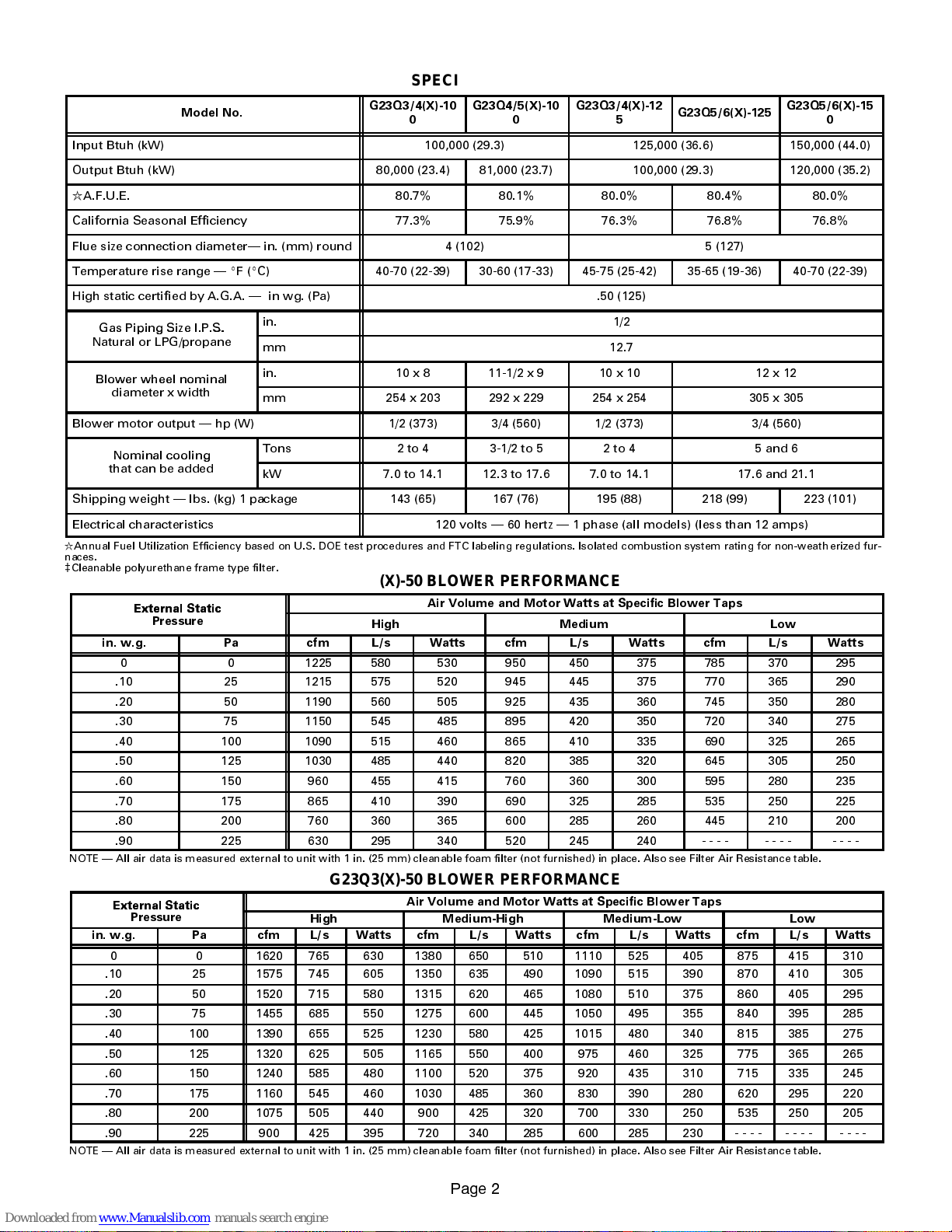
Input Btuh (kW) 100,000 (29.3) 125,000 (36.6) 150,000 (44.0)
Output Btuh (kW) 80,000 (23.4) 81,000 (23.7) 100,000 (29.3) 120,000 (35.2)
R
A.F.U.E. 80.7% 80.1% 80.0% 80.4% 80.0%
California Seasonal Efficiency 77.3% 75.9% 76.3% 76.8% 76.8%
Flue size connection diameter in. (mm) round 4 (102) 5 (127)
Temperature rise range EF(EC) 40-70 (22-39) 30-60 (17-33) 45-75 (25-42) 35-65 (19-36) 40-70 (22-39)
High static certified by A.G.A. in wg. (Pa) .50 (125)
Gas Piping Size I.P.S.
Natural or LPG/propane
Blower wheel nominal
diameter x width
Blower motor output hp (W) 1/2 (373) 3/4 (560) 1/2 (373) 3/4 (560)
Nominal cooling
that can be added
Shipping weight lbs. (kg) 1 package 143 (65) 167 (76) 195 (88) 218 (99) 223 (101)
Electrical characteristics 120 volts 60 hertz 1 phase (all models) (less than 12 amps)
R
Annual Fuel Utilization Efficiency based on U.S. DOE test procedures and FTC labeling regulations. Isolated combustion system rating for non-weath erized fur-
naces.
c
Cleanable polyurethane frame type filter.
in. 1/2
.
mm 12.7
in. 10x8 11-1/2 x 9 10x10 12x12
mm 254 x 203 292 x 229 254 x 254 305 x 305
Tons 2to4 3-1/2 to 5 2to4 5 and 6
kW 7.0 to 14.1 12.3 to 17.6 7.0 to 14.1 17.6 and 21.1
G23Q3/4(X)-100G23Q4/5(X)-100G23Q3/4(X)-12
5
G23Q5/6(X)-125
G23Q5/6(X)-15
0
G23Q2(X)-50 BLOWER PERFORMANCE
Air Volume and Motor Watts at Specific Blower Taps
Pressure
in. w.g. Pa cfm L/s Watts cfm L/s Watts cfm L/s Watts
0 0 1225 580 530 950 450 375 785 370 295
.10 25 1215 575 520 945 445 375 770 365 290
.20 50 1190 560 505 925 435 360 745 350 280
.30 75 1150 545 485 895 420 350 720 340 275
.40 100 1090 515 460 865 410 335 690 325 265
.50 125 1030 485 440 820 385 320 645 305 250
.60 150 960 455 415 760 360 300 595 280 235
.70 175 865 410 390 690 325 285 535 250 225
.80 200 760 360 365 600 285 260 445 210 200
.90 225 630 295 340 520 245 240 ---- ---- ----
NOTE All air data is measured external to unit with 1 in. (25 mm) cleanable foam filter (not furnished) in place. Also see Filter Air Resistance table.
High Medium Low
G23Q3(X)-50 BLOWER PERFORMANCE
External Static
Pressure
in. w.g. Pa cfm L/s Watts cfm L/s Watts cfm L/s Watts cfm L/s Watts
0 0 1620 765 630 1380 650 510 1110 525 405 875 415 310
.10 25 1575 745 605 1350 635 490 1090 515 390 870 410 305
.20 50 1520 715 580 1315 620 465 1080 510 375 860 405 295
.30 75 1455 685 550 1275 600 445 1050 495 355 840 395 285
.40 100 1390 655 525 1230 580 425 1015 480 340 815 385 275
.50 125 1320 625 505 1165 550 400 975 460 325 775 365 265
.60 150 1240 585 480 1100 520 375 920 435 310 715 335 245
.70 175 1160 545 460 1030 485 360 830 390 280 620 295 220
.80 200 1075 505 440 900 425 320 700 330 250 535 250 205
.90 225 900 425 395 720 340 285 600 285 230 ---- ---- ----
NOTE All air data is measured external to unit with 1 in. (25 mm) cleanable foam filter (not furnished) in place. Also see Filter Air Resistance table.
High Medium-High Medium-Low Low
Air Volume and Motor Watts at Specific Blower Taps
3DJH
Page 3
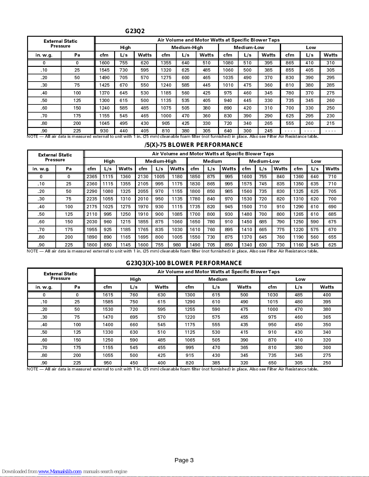
G23Q2/3(X)-75 BLOWER PERFORMANCE
External Static
External Static
External Static
External Static
Pressure
in. w.g. Pa cfm L/s Watts cfm L/s Watts cfm L/s Watts cfm L/s Watts
0 0 1600 755 620 1355 640 510 1080 510 395 865 410 310
.10 25 1545 730 595 1320 625 485 1060 500 385 855 405 305
.20 50 1490 705 570 1275 600 465 1035 490 370 830 390 295
.30 75 1425 670 550 1240 585 445 1010 475 360 810 380 285
.40 100 1370 645 530 1185 560 425 975 460 345 780 370 275
.50 125 1300 615 500 1135 535 405 940 445 330 735 345 260
.60 150 1240 585 485 1075 505 380 890 420 310 700 330 250
.70 175 1155 545 465 1000 470 360 830 390 290 625 295 230
.80 200 1045 495 430 905 425 330 720 340 265 555 260 215
.90 225 930 440 405 810 380 305 640 300 245 ---- ---- ----
NOTE All air data is measured external to unit with 1 in. (25 mm) cleanable foam filter (not furnished) in place. Also see Filter Air Resistance table.
High Medium-High Medium-Low Low
Air Volume and Motor Watts at Specific Blower Taps
G23Q4/5(X)-75 BLOWER PERFORMANCE
External Static
Pressure
in. w.g. Pa cfm L/s Watts cfm L/s Watts cfm L/s Watts cfm L/s Watts cfm L/s Watts
0 0 2365 1115 1360 2130 1005 1180 1850 875 995 1600 755 840 1360 640 710
.10 25 2360 1115 1355 2105 995 1175 1830 865 995 1575 745 835 1350 635 710
.20 50 2290 1080 1325 2055 970 1155 1800 850 985 1560 735 830 1325 625 705
.30 75 2235 1055 1310 2010 950 1135 1780 840 970 1530 720 820 1310 620 700
.40 100 2175 1025 1275 1970 930 1115 1735 820 945 1500 710 910 1290 610 690
.50 125 2110 995 1250 1910 900 1085 1700 800 930 1480 700 800 1265 610 685
.60 150 2030 960 1215 1855 875 1060 1650 780 910 1450 685 790 1250 590 675
.70 175 1955 925 1185 1765 835 1030 1610 760 895 1410 665 775 1220 575 670
.80 200 1890 890 1165 1695 800 1005 1550 730 875 1370 645 760 1190 560 655
.90 225 1800 850 1145 1600 755 980 1490 705 850 1340 630 730 1160 545 625
NOTE All air data is measured external to unit with 1 in. (25 mm) cleanable foam filter (not furnished) in place. Also see Filter Air Resistance table.
High Medium-High Medium Medium-Low Low
Air Volume and Motor Watts at Specific Blower Taps
G23Q3(X)-100 BLOWER PERFORMANCE
Air Volume and Motor Watts at Specific Blower Taps
Pressure
in. w.g. Pa cfm L/s Watts cfm L/s Watts cfm L/s Watts
0 0 1615 760 630 1300 615 500 1030 485 400
.10 25 1585 750 615 1290 610 490 1015 480 395
.20 50 1530 720 595 1255 590 475 1000 470 380
.30 75 1470 695 570 1220 575 455 975 460 365
.40 100 1400 660 545 1175 555 435 950 450 350
.50 125 1330 630 510 1125 530 415 910 430 340
.60 150 1250 590 485 1065 505 390 870 410 320
.70 175 1155 545 455 995 470 365 810 380 300
.80 200 1055 500 425 915 430 345 735 345 275
.90 225 950 450 400 820 385 320 650 305 250
NOTE All air data is measured external to unit with 1 in. (25 mm) cleanable foam filter (not furnished) in place. Also see Filter Air Resistance table.
High Medium Low
3DJH
Page 4
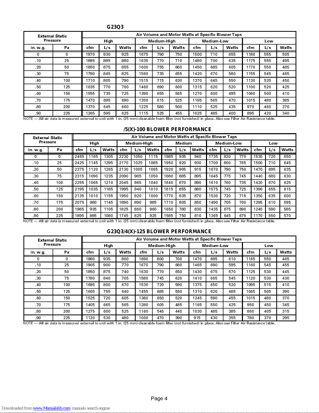
G23Q3/4(X)-100 BLOWER PERFORMANCE
External Static
External Static
External Static
Air Volume and Motor Watts at Specific Blower Taps
Pressure
in. w.g. Pa cfm L/s Watts cfm L/s Watts cfm L/s Watts cfm L/s Watts
0 0 1970 930 925 1675 790 750 1500 710 655 1180 555 505
.10 25 1895 895 880 1635 770 710 1480 700 635 1175 555 495
.20 50 1850 875 855 1600 755 680 1450 685 605 1170 550 485
.30 75 1790 845 825 1560 735 655 1420 670 580 1155 545 465
.40 100 1710 805 790 1515 715 630 1370 645 550 1130 535 450
.50 125 1635 770 760 1460 690 600 1315 620 520 1100 520 425
.60 150 1555 735 725 1390 655 565 1270 600 495 1060 500 410
.70 175 1470 695 690 1300 615 525 1195 565 470 1015 480 385
.80 200 1370 645 660 1225 580 500 1110 525 435 970 460 370
.90 225 1265 595 625 1115 525 455 1025 485 400 895 420 340
NOTE All air data is measured external to unit with 1 in. (25 mm) cleanable foam filter (not furnished) in place. Also see Filter Air Resistance table.
High Medium-High Medium-Low Low
G23Q4/5(X)-100 BLOWER PERFORMANCE
External Static
Pressure
in. w.g. Pa cfm L/s Watts cfm L/s Watts cfm L/s Watts cfm L/s Watts cfm L/s Watts
0 0 2465 1165 1305 2230 1050 1115 1985 935 940 1735 820 770 1530 720 650
.10 25 2425 1145 1295 2170 1025 1085 1950 920 930 1700 800 765 1500 710 645
.20 50 2375 1120 1265 2130 1005 1065 1920 905 915 1670 790 750 1470 695 635
.30 75 2315 1090 1235 2090 985 1050 1880 885 895 1645 775 745 1440 680 630
.40 100 2255 1065 1210 2045 965 1040 1840 870 890 1610 760 735 1420 670 625
.50 125 2195 1035 1185 1995 940 1010 1815 855 880 1575 745 725 1390 655 615
.60 150 2135 1010 1155 1950 920 1000 1770 835 870 1530 720 715 1350 635 600
.70 175 2075 980 1145 1890 890 985 1710 805 850 1490 705 700 1295 610 595
.80 200 1985 935 1105 1825 860 960 1650 780 830 1435 675 690 1245 590 585
.90 225 1895 895 1080 1745 825 925 1585 750 810 1365 645 675 1170 550 570
NOTE All air data is measured external to unit with 1 in. (25 mm) cleanable foam filter (not furnished) in place. Also see Filter Air Resistance table.
High Medium-High Medium Medium-Low Low
Air Volume and Motor Watts at Specific Blower Taps
G23Q3/4(X)-125 BLOWER PERFORMANCE
External Static
Pressure
in. w.g. Pa cfm L/s Watts cfm L/s Watts cfm L/s Watts cfm L/s Watts
0 0 1980 935 800 1690 800 700 1470 695 610 1165 550 465
.10 25 1905 900 770 1670 790 680 1465 690 595 1160 545 455
.20 50 1850 875 740 1630 770 650 1430 675 570 1125 530 445
.30 75 1780 840 705 1580 745 620 1410 665 545 1120 530 430
.40 100 1695 800 670 1530 720 590 1375 650 520 1095 515 410
.50 125 1605 755 640 1455 685 550 1310 620 485 1065 505 390
.60 150 1525 720 605 1380 650 520 1245 590 455 1015 480 370
.70 175 1405 665 565 1280 605 485 1165 550 425 950 450 345
.80 200 1275 600 525 1160 545 440 1030 485 385 860 405 315
.90 225 1120 530 480 1000 470 390 915 430 355 780 370 295
NOTE All air data is measured external to unit with 1 in. (25 mm) cleanable foam filter (not furnished) in place. Also see Filter Air Resistance table.
High Medium-High Medium-Low Low
Air Volume and Motor Watts at Specific Blower Taps
3DJH
Page 5
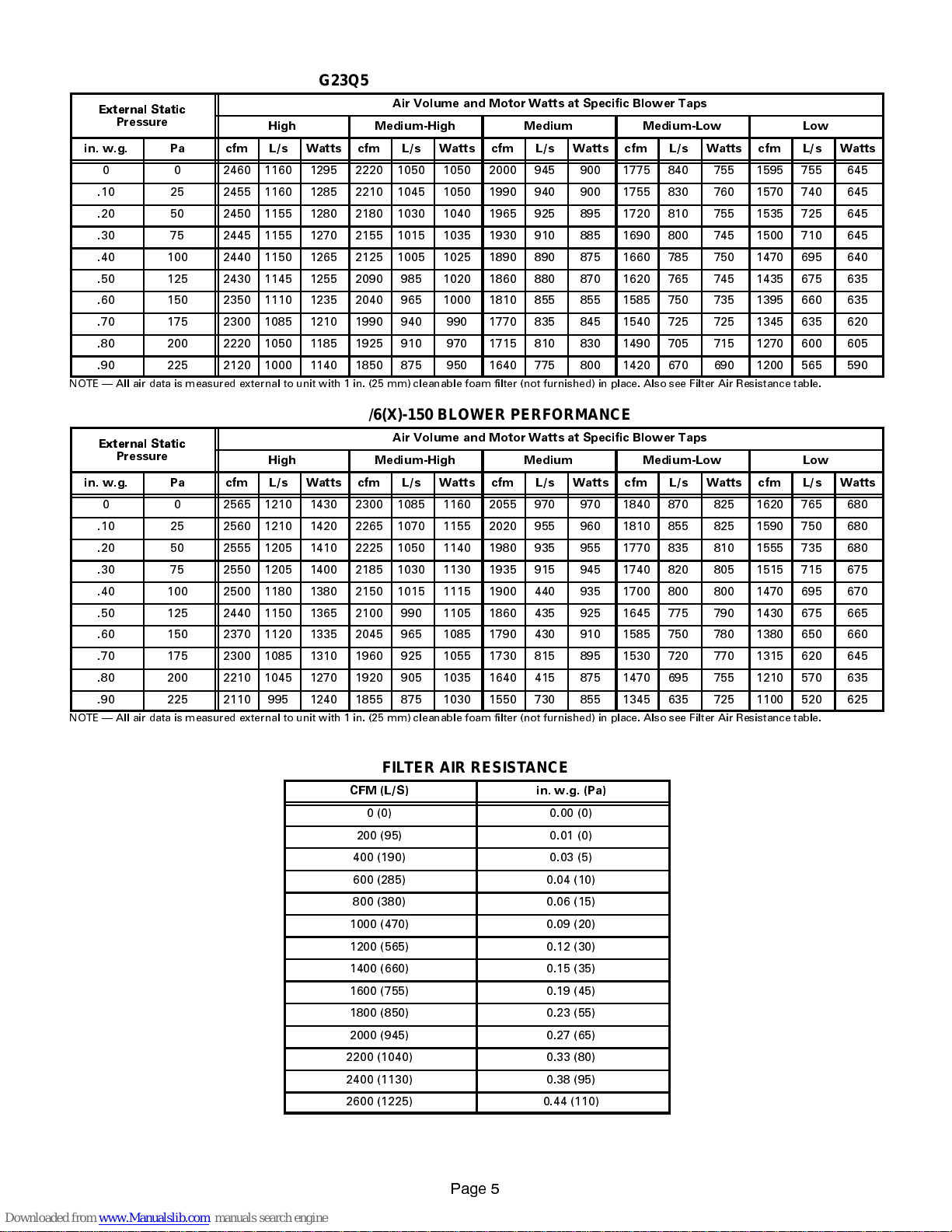
G23Q5/6(X)-125 BLOWER PERFORMANCE
External Static
External Static
External Static
Pressure
in. w.g. Pa cfm L/s Watts cfm L/s Watts cfm L/s Watts cfm L/s Watts cfm L/s Watts
0 0 2460 1160 1295 2220 1050 1050 2000 945 900 1775 840 755 1595 755 645
.10 25 2455 1160 1285 2210 1045 1050 1990 940 900 1755 830 760 1570 740 645
.20 50 2450 1155 1280 2180 1030 1040 1965 925 895 1720 810 755 1535 725 645
.30 75 2445 1155 1270 2155 1015 1035 1930 910 885 1690 800 745 1500 710 645
.40 100 2440 1150 1265 2125 1005 1025 1890 890 875 1660 785 750 1470 695 640
.50 125 2430 1145 1255 2090 985 1020 1860 880 870 1620 765 745 1435 675 635
.60 150 2350 1110 1235 2040 965 1000 1810 855 855 1585 750 735 1395 660 635
.70 175 2300 1085 1210 1990 940 990 1770 835 845 1540 725 725 1345 635 620
.80 200 2220 1050 1185 1925 910 970 1715 810 830 1490 705 715 1270 600 605
.90 225 2120 1000 1140 1850 875 950 1640 775 800 1420 670 690 1200 565 590
NOTE All air data is measured external to unit with 1 in. (25 mm) cleanable foam filter (not furnished) in place. Also see Filter Air Resistance table.
High Medium-High Medium Medium-Low Low
Air Volume and Motor Watts at Specific Blower Taps
G23Q5/6(X)-150 BLOWER PERFORMANCE
External Static
Pressure
in. w.g. Pa cfm L/s Watts cfm L/s Watts cfm L/s Watts cfm L/s Watts cfm L/s Watts
0 0 2565 1210 1430 2300 1085 1160 2055 970 970 1840 870 825 1620 765 680
.10 25 2560 1210 1420 2265 1070 1155 2020 955 960 1810 855 825 1590 750 680
.20 50 2555 1205 1410 2225 1050 1140 1980 935 955 1770 835 810 1555 735 680
.30 75 2550 1205 1400 2185 1030 1130 1935 915 945 1740 820 805 1515 715 675
.40 100 2500 1180 1380 2150 1015 1115 1900 440 935 1700 800 800 1470 695 670
.50 125 2440 1150 1365 2100 990 1105 1860 435 925 1645 775 790 1430 675 665
.60 150 2370 1120 1335 2045 965 1085 1790 430 910 1585 750 780 1380 650 660
.70 175 2300 1085 1310 1960 925 1055 1730 815 895 1530 720 770 1315 620 645
.80 200 2210 1045 1270 1920 905 1035 1640 415 875 1470 695 755 1210 570 635
.90 225 2110 995 1240 1855 875 1030 1550 730 855 1345 635 725 1100 520 625
NOTE All air data is measured external to unit with 1 in. (25 mm) cleanable foam filter (not furnished) in place. Also see Filter Air Resistance table.
High Medium-High Medium Medium-Low Low
Air Volume and Motor Watts at Specific Blower Taps
FILTER AIR RESISTANCE
CFM (L/S) in. w.g. (Pa)
0 (0) 0.00 (0)
200 (95) 0.01 (0)
400 (190) 0.03 (5)
600 (285) 0.04 (10)
800 (380) 0.06 (15)
1000 (470) 0.09 (20)
1200 (565) 0.12 (30)
1400 (660) 0.15 (35)
1600 (755) 0.19 (45)
1800 (850) 0.23 (55)
2000 (945) 0.27 (65)
2200 (1040) 0.33 (80)
2400 (1130) 0.38 (95)
2600 (1225) 0.44 (110)
3DJH
Page 6
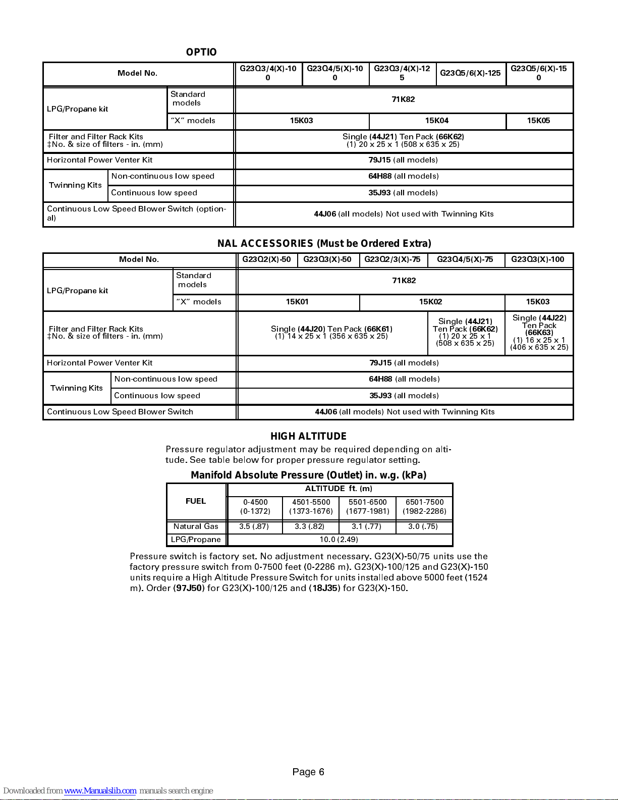
OPTIONAL ACCESSORIES (Must be Ordered Extra)
LPG/Propane kit
LPG/Propane kit
Model No.
Standard
LPG/Propane kit
Filter and Filter Rack Kits
c
No. & size of filters - in. (mm)
Horizontal Power Venter Kit
Twinning Kits
Continuous Low Speed Blower Switch (option-
al)
Non-continuous low speed
Continuous low speed
models
X models
OPTIONAL ACCESSORIES (Must be Ordered Extra)
Model No. G23Q2(X)-50 G23Q3(X)-50 G23Q2/3(X)-75 G23Q4/5(X)-75 G23Q3(X)-100
Standard
LPG/Propane kit
Filter and Filter Rack Kits
c
No. & size of filters - in. (mm)
Horizontal Power Venter Kit
Twinning Kits
Continuous Low Speed Blower Switch
Non-continuous low speed
Continuous low speed
models
X models
G23Q3/4(X)-100G23Q4/5(X)-100G23Q3/4(X)-12
15K03 15K04 15K05
Single
(44J21)
(1) 20 x 25 x 1 (508 x 635 x 25)
79J15
64H88
35J93
44J06
(all models) Not used with Twinning Kits
15K01 15K02 15K03
Single
(44J20)
(1) 14 x 25 x 1 (356 x 635 x 25)
Ten Pack
44J06
(66K61)
79J15
64H88
35J93
(all models) Not used with Twinning Kits
5
71K82
Ten Pack
(all models)
(all models)
(all models)
71K82
(all models)
(all models)
(all models)
G23Q5/6(X)-125
(66K62)
Single
Ten Pack
(44J21)
(66K62)
(1) 20 x 25 x 1
(508 x 635 x 25)
G23Q5/6(X)-15
0
Single
(44J22)
Ten Pack
(66K63)
(1)16x25x1
(406 x 635 x 25)
HIGH ALTITUDE
Pressure regulator adjustment may be required depending on alti-
tude. See table below for proper pressure regulator setting.
Manifold Absolute Pressure (Outlet) in. w.g. (kPa)
ALTITUDE ft. (m)
FUEL
Natural Gas 3.5 (.87) 3.3 (.82) 3.1 (.77) 3.0 (.75)
LPG/Propane 10.0 (2.49)
Pressure switch is factory set. No adjustment necessary. G23(X)-50/75 units use the
factory pressure switch from 0-7500 feet (0-2286 m). G23(X)-100/125 and G23(X)-150
units require a High Altitude Pressure Switch for units installed above 5000 feet (1524
m). Order (
97J50
) for G23(X)-100/125 and (
0-4500
(0-1372)
4501-5500
(1373-1676)
18J35
5501-6500
(1677-1981)
) for G23(X)-150.
6501-7500
(1982-2286)
3DJH
Page 7
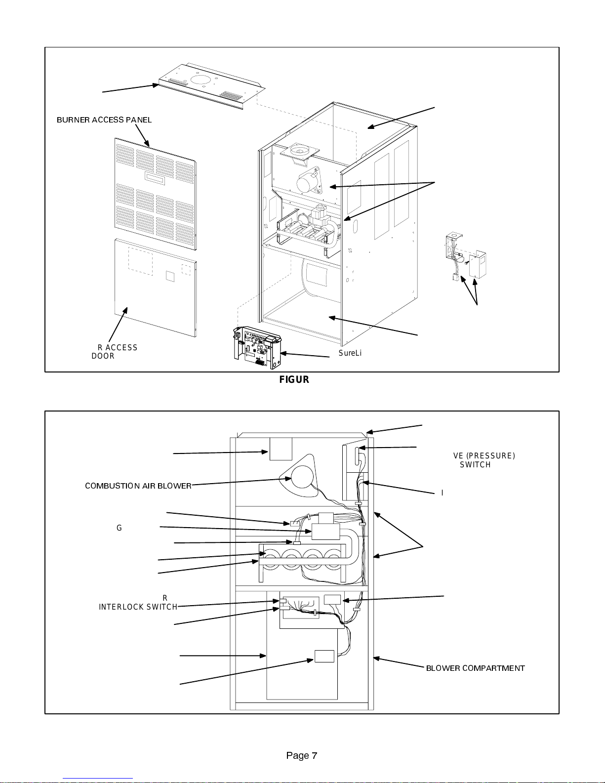
TOP PANEL
BURNER ACCESS PANEL
BLOWER ACCESS
DOOR
G23(X) ORIENTATION
SUPPLY AIR OPENING
HEATING COMPARTMENT
MAKE-UP BOX ASSEMBLY
BLOWER COMPARTMENT
SureLight Control
(-5 and -6 models only)
FLUE TRANSITION
COMBUSTION AIR BLOWER
PRIMARY LIMIT
GAS VALVE
ROLLOUT SWITCH
BURNERS
MANIFOLD
BLOWER DOOR
INTERLOCK SWITCH
CIRCUIT BREAKER
SUPPLY AIR BLOWER
FIGURE 1
G23(X) GENERAL PARTS ORIENTATION
SUPPLY AIR DUCT FLANGE
COMBUSTION AIR BLOWER
PROVE (PRESSURE)
SWITCH
IGNITION CONTROL
(-1 through -4 models only)
HEATING COMPARTMENT
CONTROL BOX
BLOWER COMPARTMENT
BLOWER CAPACITOR
FIGURE 2
3DJH
Page 8
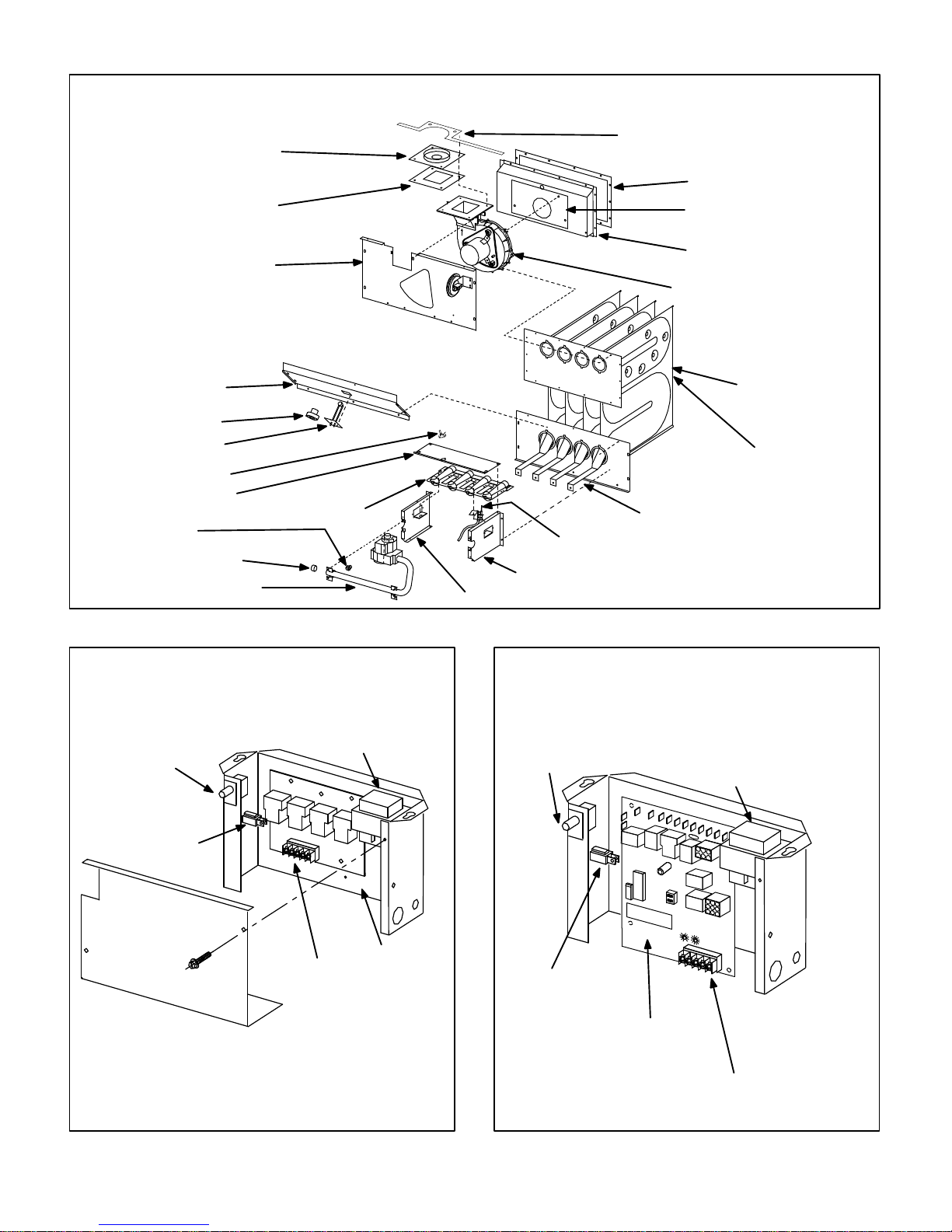
(FLUE TRANSITION ASSEMBLY)
FIGURE4
FIGURE5
ORIFICE PLATE
FLUE OUTLET
GLASS FIBER GASKET
UPPER VEST
PANEL
G23(X) HEAT EXCHANGE ASSEMBLY
-5 and -6 G23X Models
TOP CAP
GLASS FIBER
GASKET
FLUE BOX
GLASS FIBER GASKET
COMBUSTION BLOWER
GLASS FIBER GASKET
FLUE COLLECTOR
BOX
COMBUSTION AIR BLOWER
MID VEST PANEL
PRIMARY LIMIT
PRIMARY LIMIT
ALTERNATE STYLE
ROLLOUT SWITCH
ROLLOUT BRACKET
ORIFICE
MANIFOLD END PLUG
MANIFOLD AND GAS VALVE
CONTROL BOX
(-1 through -4 G23X models)
DOOR INTERLOCK
SWITCH
BURNER ASSEMBLY
TRANSFORMER
HEATEXCHANGER
(Heat Train
Assembly)
CLAMSHELL
(Each Segment)
FLAME BAFFLES (NOx UNITS ONLY)
FLAME SENSE ASSEMBLY
RIGHT MANIFOLD BRACKET
LEFT MANIFOLD BRACKET
FIGURE 3
CONTROL BOX
(-5 and -6 G23X models))
DOOR INTERLOCK
SWITCH
TRANSFORMER
CIRCUIT BREAKER
LOW VOLTAGE STRIP
BCC CONTROL
CIRCUIT BREAKER
SURELIGHT CONTROL
LOW VOLTAGE STRIP
Page 8
Page 9
I-UNIT COMPONENTS (Figures 1 and 2)
G23(X)unitcomponentsareshowninfigures1and2.The
gasvalve,ignitioncontrolandburnerscanbeaccessedby
removing the burner access panel. The blower, blower
control and SureLight control can be accessed by removing the blower access door.
G23(X) units are factory equipped with bottom and side return
air panels in place. The panels are designed to be field removed as required for bottom air return or side air return.
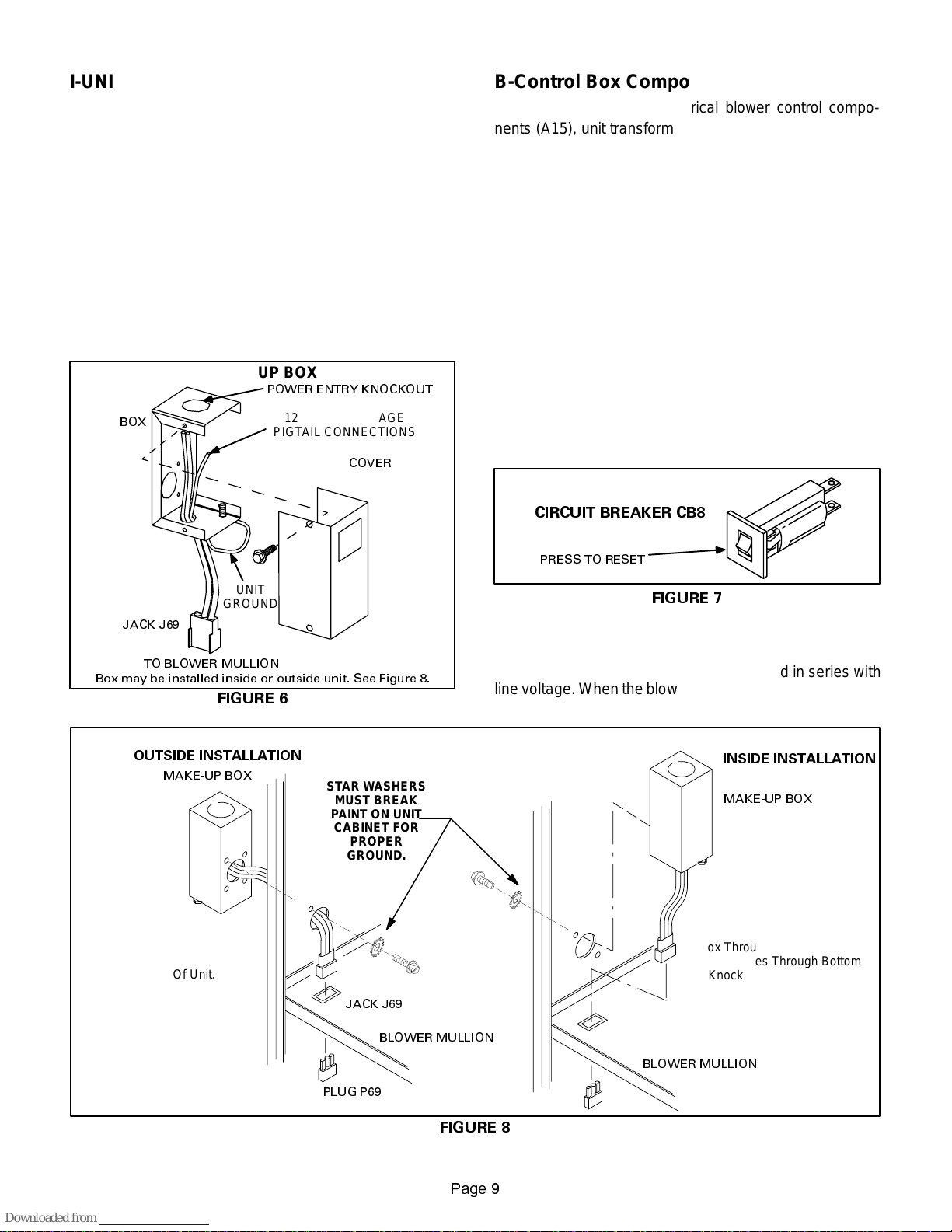
A-Make-Up Box (Figure 6)
Thelinevoltagemake-upboxisshowninfigure6.Thebox
may be installed inside or outside the unit and may be
installed on the unit left or right side (figure 8).
MAKE-UP BOX
POWER ENTRY KNOCKOUT
BOX
120V LINE VOLTAGE
PIGTAIL CONNECTIONS
COVER
B-Control Box Components (Figures 4 & 5)
SureLight control (A3), Electrical blower control components (A15), unit transformer (T1) and 24V circuit breaker
(CB8)are located in the controlbox. In addition, a door interlockswitch(S51)islocatedin thecontrolbox.Jackplugs
allow the control box to be easily removed for blower service.
1. Control Transformer (T1)
Atransformer locatedinthe controlbox provides powerto
thelow voltage 24volt section of the unit.Transformers on
all models are rated 40VA with a 120V primary and a 24V
secondary.
2. Circuit Breaker (CB8)
A24Vcircuit br eaker isalso locate d in the c ontrol box .
The switch provides ove rcurr ent protec tion to the
transformer ( T1). Thebreaker is rated3A at 32V.Ifthe
currente xcee dsthis limitthebreakerwill tr ipand allunit
operation will shut down. T he brea ker can bemanually
reset by pres sing the button on the face. See figure 7.
CIRCUIT BREAKER CB8
UNIT
GROUND
JACK J69
Box may be installed inside or outside unit. See Figure 8.
TO BLOWER MULLION
FIGURE 6
MAKE-UP BOX INSTALLATION
OUTSIDE INSTALLATION
MAKE-UP BOX
Line Voltage Enters Through
Knockout In Make-Up Box. J69
Passes Through Side Knockout
Into Side Of Unit.
Box may be installed inside or outside cabinet and may
be installed on left side or right side of cabinet
STARWASHERS
MUST BREAK
PAINT ON UNIT
CABINET FOR
PROPER
GROUND.
UNIT
CABINET
JACK J69
PRESS TO RESET
FIGURE 7
3.Door Interlock Switch (S51)
A door interlock switch rated 14A at 125VACislocated on
the blower access door.The switch is wired in series with
linevoltage. When the blower dooris removed theunitwill
shut down.
INSIDE INSTALLATION
MAKE-UP BOX
Line Voltage Enters Make-Up
Box Through Side Of Unit and
J69 Passes Through Bottom
Knockout in Make-Up Box.
BLOWER MULLION
BLOWER MULLION
PLUG P69
FIGURE 8
3DJH
Page 10
4. BCC Blower Control (A15)
-1 Through -4 Models
G23(X)-1, -2, -3 and -4 model units utilize the BCC blower
controlmanufacturedby Heatcraft. Seefigure10.TheBCC
is a printed circuit board which controls the supply air blower and monitors primary limit and gas valve operation. The
BCC is equipped with a jumper for electronic (isolation
relay) or electro-mechanical thermostat selection.The controlhasanon-adjustable,factorypresetfan“on”timing.Fan
“off”timing is adjustable. The board is divided into two sections, 120 and 24VAC. Line voltage comes into the board
on the 120VACside. See table 1 for terminal designations.
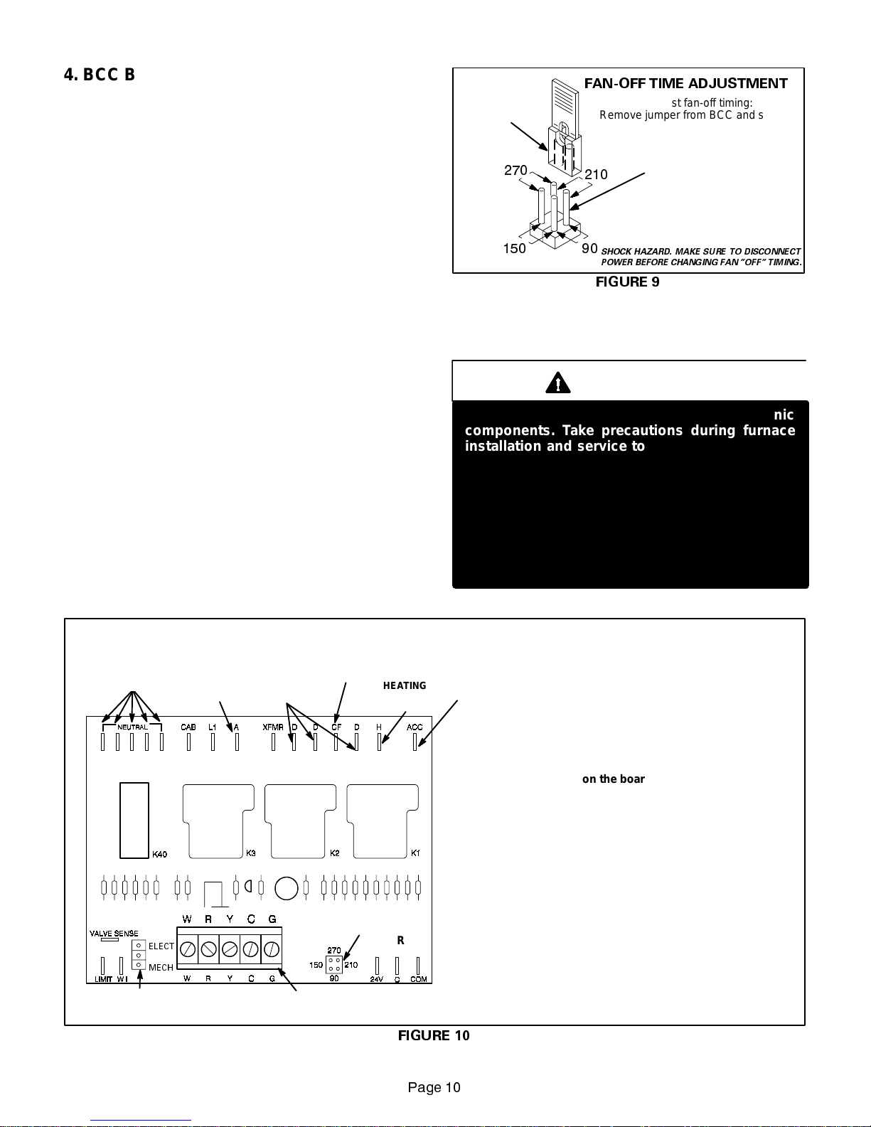
Fan Timings
Fan“off”timing (time that thebloweroperates after theheat
demand has been satisfied) is determined by the arrangement of a jumper across pins on the BCC blower control
board.Seefigure9.To adjust fan“off”timing,gentlydisconnect jumper and reposition across pins corresponding with
newtiming.Fan “on” time is factoryset at 45 seconds andis
not adjustable.
NOTE—If fan “off” time is set too low, residual heat in
heat exchanger may cause primary limit S10 to trip resulting in frequent cycling of blower. If this occurs, adjust blower to longer time setting.
Figure 9 shows the various fan “off” timings and how jumper
should be positioned. Unit is shipped with a factory fan “off”
setting of 90 seconds. Fan “off” time will affect comfort and
efficiency and is adjustable to satisfy individual applications.
Thefan “off” timing is initiated aftera heating demand butnot
after a blower or cooling demand (that is, when indoor thermostat switch is changed from ON to AUTO and heating/
cooling demand is not present, the blower stops immediately).
FAN-OFF TIME ADJUSTMENT
TIMING
JUMPER
To adjust fan-off timing:
Remove jumper from BCC and select
one of the other pin combinations to
achieve the desired time.
TIMING PINS
(seconds)
Leave jumper off for
330 second fan-off timing.
SHOCK HAZARD. MAKE SURE TO DISCONNECT
POWER BEFORE CHANGING FAN OFF TIMING.
FIGURE 9
ELECTROSTATIC DISCHARGE (ESD)
Precautions and Procedures
CAUTION
Electrostatic discharge can affect electronic
components. Take precautions during furnace
installation and service to protect the furnace’s
electroniccontrols.Precautions will helptoavoid
control exposure to electrostatic discharge by
putting the furnace, the control and the technician at the same electrostatic potential. Neutralize electrostatic charge by touching hand and all
tools on an unpainted unit surface, such as the
gas valve or blower deck, before performing any
service procedure.
NEUTRAL
TERMINALS
ELECT
MECH
THERMOSTATJUMPER
(Electronic or Mechanical)
G23(X)-1, -2 ,-3 and -4 MODELS
BLOWER CONTROL - BCC
COOLING
SPEED TAP
TERMINAL
(DETACHABLE ON EARLY BOARDS ONLY))
TERMINALS
THERMOSTATTERMINAL STRIP
CONTINUOUS FAN
DUMMY
TERMINAL
BLOWER TIME
ADJUSTMENT
JUMPER
(A15)
HEATING
SPEED TAP
TERMINAL
FIGURE 10
ACCESSORY
TERMINAL
Heat Anticipator Settings
Beginning with the BCC3-2 series, a 3 pin jumper
has been installed on the board next to the removable 24V terminal strip to account for both programmable and electromechanical thermostat usage in
the field. For electromechanical thermostat, position
the jumper over the middle and bottom pin labeled
”MECH.” Set the heat anticipator setting to 0.65
amps for Honeywell valves or 0.50 amps for White
Rodgers valves. For programmable (electronic) thermostats, position the jumper over the middle and
top pin labeled ”ELECT.” Set the heat anticipator
setting to 0.1 amps.
3DJH
Page 11
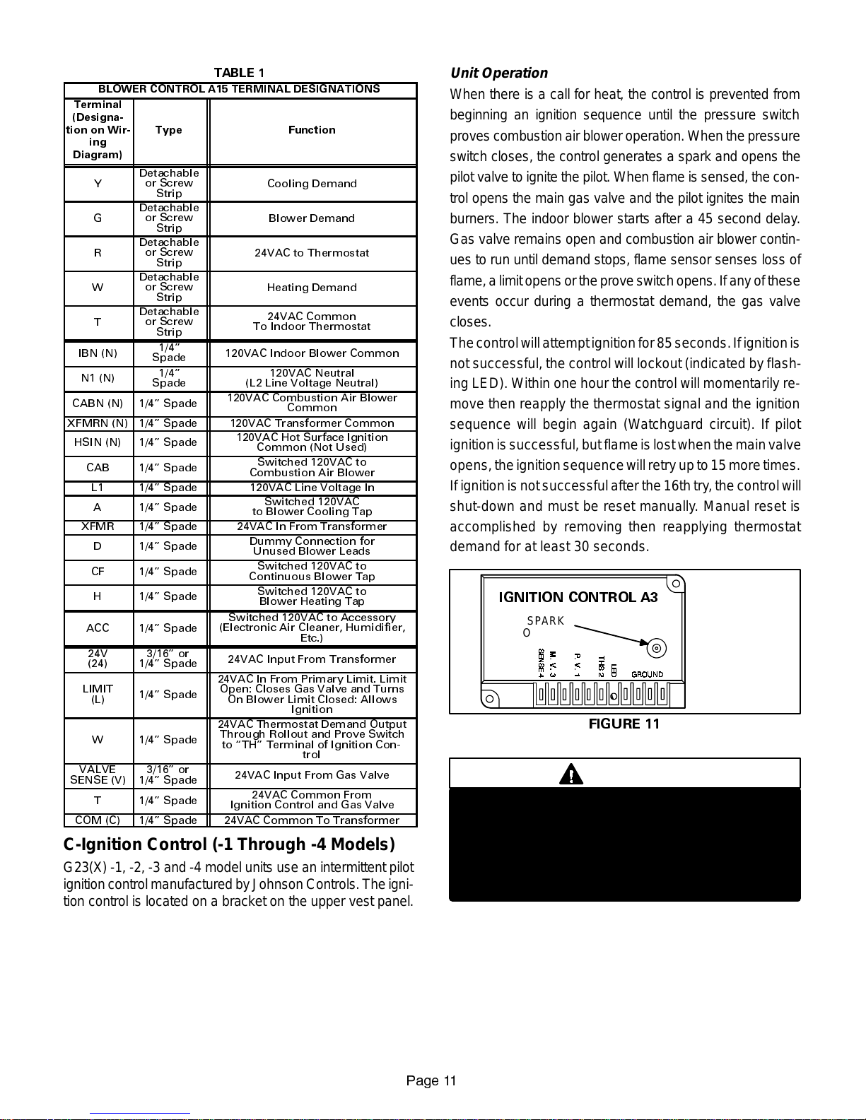
TABLE 1
BLOWER CONTROL A15 TERMINAL DESIGNATIONS
Terminal
(Designa-
tion on Wir-
ing
Diagram)
Y
G
R
W
T
IBN (N)
N1 (N)
CABN (N) 1/4 Spade
XFMRN (N) 1/4 Spade 120VAC Transformer Common
HSIN (N) 1/4 Spade
CAB 1/4 Spade
L1 1/4 Spade 120VAC Line Voltage In
A 1/4 Spade
XFMR 1/4 Spade 24VAC In From Transformer
D 1/4 Spade
CF 1/4 Spade
H 1/4 Spade
ACC 1/4 Spade
24V
(24)
LIMIT
(L)
W 1/4 Spade
VALVE
SENSE (V)
T 1/4 Spade
COM (C) 1/4 Spade 24VAC Common To Transformer
Type Function
Detachable
or Screw
Strip
Detachable
or Screw
Strip
Detachable
or Screw
Strip
Detachable
or Screw
Strip
Detachable
or Screw
Strip
1/4
Spade
1/4
Spade
3/16 or
1/4 Spade
1/4 Spade
3/16 or
1/4 Spade
120VAC Indoor Blower Common
(Electronic Air Cleaner, Humidifier,
24VAC In From Primary Limit. Limit
Open: Closes Gas Valve and Turns
24VAC Thermostat Demand Output
Through Rollout and Prove Switch
to TH Terminal of Ignition Con-
Cooling Demand
Blower Demand
24VAC to Thermostat
Heating Demand
24VAC Common
To Indoor Thermostat
120VAC Neutral
(L2 Line Voltage Neutral)
120VAC Combustion Air Blower
120VAC Hot Surface Ignition
Switched 120VAC to Accessory
24VAC Input From Transformer
On Blower Limit Closed: Allows
24VAC Input From Gas Valve
Ignition Control and Gas Valve
Common
Common (Not Used)
Switched 120VAC to
Combustion Air Blower
Switched 120VAC
to Blower Cooling Tap
Dummy Connection for
Unused Blower Leads
Switched 120VAC to
Continuous Blower Tap
Switched 120VAC to
Blower Heating Tap
24VAC Common From
Etc.)
Ignition
trol
C-Ignition Control (-1 Through -4 Models)
G23(X) -1, -2, -3 and -4 model units use an intermittent pilot
ignitioncontrol manufacturedby Johnson Controls. The ignition control is located on a bracket on the upper vest panel.
Unit Operation
When there is a call for heat, the control is prevented from
beginning an ignition sequence until the pressure switch
proves combustion air blower operation. When the pressure
switch closes, the control generates a spark and opens the
pilot valve to ignite the pilot. When flame is sensed, the control opens the main gas valve and the pilot ignites the main
burners. The indoor blower starts after a 45 second delay.
Gas valve remains open and combustion air blower continues to run until demand stops, flame sensor senses loss of
flame,alimit opens ortheprove switchopens. If anyofthese
events occur during a thermostat demand, the gas valve
closes.
Thecontrolwillattempt ignitionfor85seconds.Ifignitionis
not successful, the control will lockout (indicated by flashing LED). Within one hour the control will momentarily remove then reapply the thermostat signal and the ignition
sequence will begin again (Watchguard circuit). If pilot
ignitionissuccessful, but flameislost whenthemainvalve
opens,theignitionsequencewill retry up to 15moretimes.
Ifignitionisnotsuccessfulafterthe16thtry,thecontrolwill
shut-down and must be reset manually. Manual reset is
accomplished by removing then reapplying thermostat
demand for at least 30 seconds.
IGNITION CONTROL A3
SPARK
OUTPUT
SEE TABLE 2
FOR TERMINAL
DESIGNATIONS
FIGURE 11
DANGER
Shock hazard.
Spark related components contain high voltage.
Disconnect power before servicing. Control is
not field repairable. If control is inoperable, simply replace entire control.
Can cause injury or death. Unsafe operation will
result if repair is attempted.
3DJH
Page 12
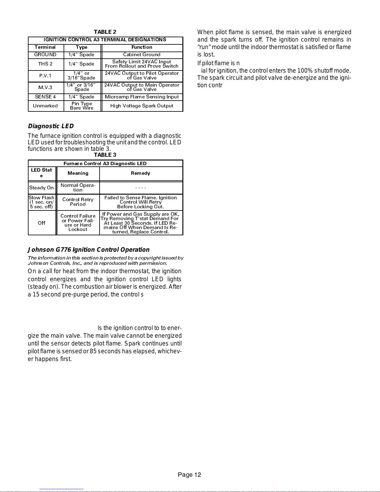
TABLE 2
IGNITION CONTROL A3 TERMINAL DESIGNATIONS
Terminal Type Function
GROUND 1/4 Spade Cabinet Ground
THS 2 1/4 Spade
P.V.1
M.V.3
SENSE 4 1/4 Spade Microamp Flame Sensing Input
Unmarked
1/4 or
3/16Spade
1/4 or 3/16
Spade
Pin Type
Bare Wire
Safety Limit 24VAC Input
From Rollout and Prove Switch
24VAC Output to Pilot Operator
24VAC Output to Main Operator
of Gas Valve
of Gas Valve
High Voltage Spark Output
Diagnostic LED
The furnace ignition control is equipped with a diagnostic
LEDusedfortroubleshootingtheunitandthe control.LED
functions are shown in table 3.
TABLE 3
Furnace Control A3 Diagnostic LED
LED Stat
e
Steady On
Slow Flash
(1 sec. on/
5 sec. off)
Off
Meaning Remedy
Normal Opera-
tion
Control Retry
Period
Control Failure
or Power Fail-
ure or Hard
Lockout
Failed to Sense Flame. Ignition
Control Will Retry
Before Locking Out.
If Power and Gas Supply are OK,
Try Removing Tstat Demand For
At Least 30 Seconds. If LED Re-
mains Off When Demand Is Re-
turned, Replace Control.
----
Johnson G776 Ignition Control Operation
The information inthis section is protected by a copyright issued by
Johnson Controls, Inc., and is reproduced with permission.
On a call for heat from the indoor thermostat, the ignition
control energizes and the ignition control LED lights
(steady on). The combustionair blower is energized.After
a 15 second pre-purge period, the control simultaneously
opens the pilot valve and sends spark to the pilot electrode.
If the pilot ignites within 85 seconds, the flame sensor detects pilot flame and signals the ignition control to to energize the main valve. The main valve cannot be energized
until the sensor detects pilot flame. Spark continues until
pilotflameissensed or 85 secondshas elapsed, whichever happens first.
When pilot flame is sensed, the main valve is energized
and the spark turns off. The ignition control remains in
“run” mode until the indoor thermostat is satisfied or flame
is lost.
Ifpilotflame is not sensedbefore the end of the85second
trialfor ignition, thecontrol enters the 100% shutoffmode.
The spark circuit and pilot valve de-energize and the ignitioncontrol automatically begins the60 minute retry delay
period. During the 60 minute delay the diagnostic LED
continually flashes on for one second and off for five seconds. After the delay period, another trial for ignition sequence starts, beginning with pre-purge.
Ifpilotflamegoesoutwhiletheindoorthermostat is calling
forheat, both main and pilotvalves de-energizewithin 0.8
seconds and remain de-energized for five seconds. After
this delay, the spark and pilot valve energize until flame is
sensedorthe85secondtrialforignitionperiod ends.Ifthis
“flameout” cycle repeats 16 times (pilot flame is established and then lost), the control locks out and the LED
goes off. A new trial for ignition sequence begins after the
thermostat contacts are opened for 30 seconds and then
closed.
If flame is detected when the thermostat calls for heat, it
must extinguish within30 seconds for normaloperation. If
flameisstillpresentafter30seconds,thecontrolgoesinto
lockout and the LED goes off.
D-Combustion Air Blower (B6)
All G23(X) units use a combustion air blower to move air
through the burners and heat exchanger during heating operation. The blower uses a shaded pole 120VAC motor.
Shaded pole motors do not use run capacitors. The motor
operates during all heating operation and is controlled by
blower control A15. The blower operates continuously while
there is a call for heat. The ignition control is prevented from
proceeding through the ignition sequence until combustion
air blower operation is sensed by the prove switch.
The pressure switch connected to the upper vest panel is
used to prove combustion air blower operation. The switch
monitors air pressure in the blower housing. During normal
operation, the pressure in the housing is negative. If the
pressure drops (becomes more positive), the pressure
switch opens. When the pressure switch opens, the ignition
control (A3) immediately closes the gas valve to prevent
burner operation.
3DJH
Page 13
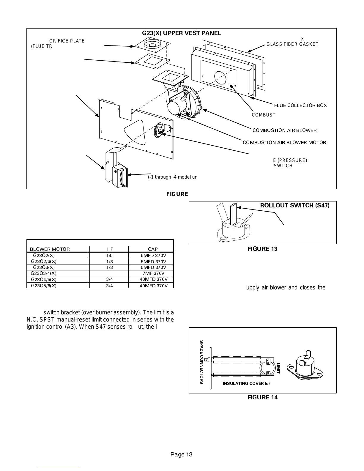
G23(X) UPPER VEST PANEL
(FLUE TRANSITION ASSEMBLY)
ORIFICE PLATE
FLUE OUT-
LET
GLASS FIBER
GASKET
UPPER VEST
PANEL
IGNITION CONTROL
BRACKET
IGNITION CONTROL
(-1 through -4 model units)
FIGURE 12
E-Blower Motors and Capacitors
All G23(X) units use direct drive blower motors. All motors
used are 120V permanent split capacitor motors to ensure
maximum efficiency. See table 4 for ratings.
TABLE 4
G23(X) BLOWER RATINGS 120V 1PH
BLOWER MOTOR HP
G23Q2(X) 1/5 5MFD 370V
G23Q2/3(X)
G23Q3(X)
G23Q3/4(X)
G23Q4/5(X)
G23Q5/6(X)
1/3
1/3
1/2
3/4 40MFD 370V
3/4 40MFD 370V
CAP
5MFD 370V
5MFD 370V
7MF 370V
F-Flame Rollout Switch (S47)
Flame rollout switch is a high temperature limit located on
rollout switch bracket (over burner assembly). The limit is a
N.C. SPST manual-reset limit connected in series with the
ignition control (A3). When S47 senses rollout, the ignition
controlimmediately stops ignitionandcloses the gas valve.
If unit is running andflame rollout is detected, the gasvalve
will close and ignition control will be disabled. Rollout can
be caused by a reverse draft, blocked flue or lack of combustion air. The switch is factory set and cannot be adjusted. The switch may have different setpoints for each
unitmodel number.However,thesetpoint will beprinted on
the side of the limit. The switch can be manually reset. To
manually reset a tripped switch, push the reset button located on the control (see figure 13).
FLUE BOX
GLASS FIBER GASKET
FLUE COLLECTOR BOX
COMBUSTION AIR BLOWER
GLASS FIBER GASKET
COMBUSTION AIR BLOWER
COMBUSTION AIR BLOWER MOTOR
COMBUSTION AIR BLOWER
PROVE (PRESSURE)
NOTE-ALL components located behind up-
per vest panel including combustion air blow-
er are exposed to supply air stream.
SWITCH
ROLLOUT SWITCH (S47)
MANUAL
RESET BUTTON
FIGURE 13
G-Primary Limit Control (S10)
Primary limit (S10) on G23(X) units is located in the middle of
the vestibule panel. When excess heat is sensed in the heat
exchanger ,the limit will open. If the limit is tripped, the furnace
control energizes the supply air blower and closes the gas
valve. The limit automatically resets when temperature retur ns to nor mal .The switch is factory set and cannot be adjusted. The switch may have different setpoints for each
unitmodel number.However,thesetpoint will be printed on
the side of the limit.
SPADE CONNECTORS
G23(X) SERIES UNITS AND ALTERNATE STYLE
LIMIT CONTROL (S10) FOR
Units may be equipped with
either style limit.
LIMIT
INSULATING COVER (s)
FIGURE 14
3DJH
Page 14
Units may be equipped with either flush style or extended
(masted) limit (figure14). Masted limits may be installed
with limit facing blower or away from blower. This orientationcannotbechanged.Whenremovinglimitfromunit,pay
careful attentionto its orientation and make sure limit is reinstalled facing same direction.
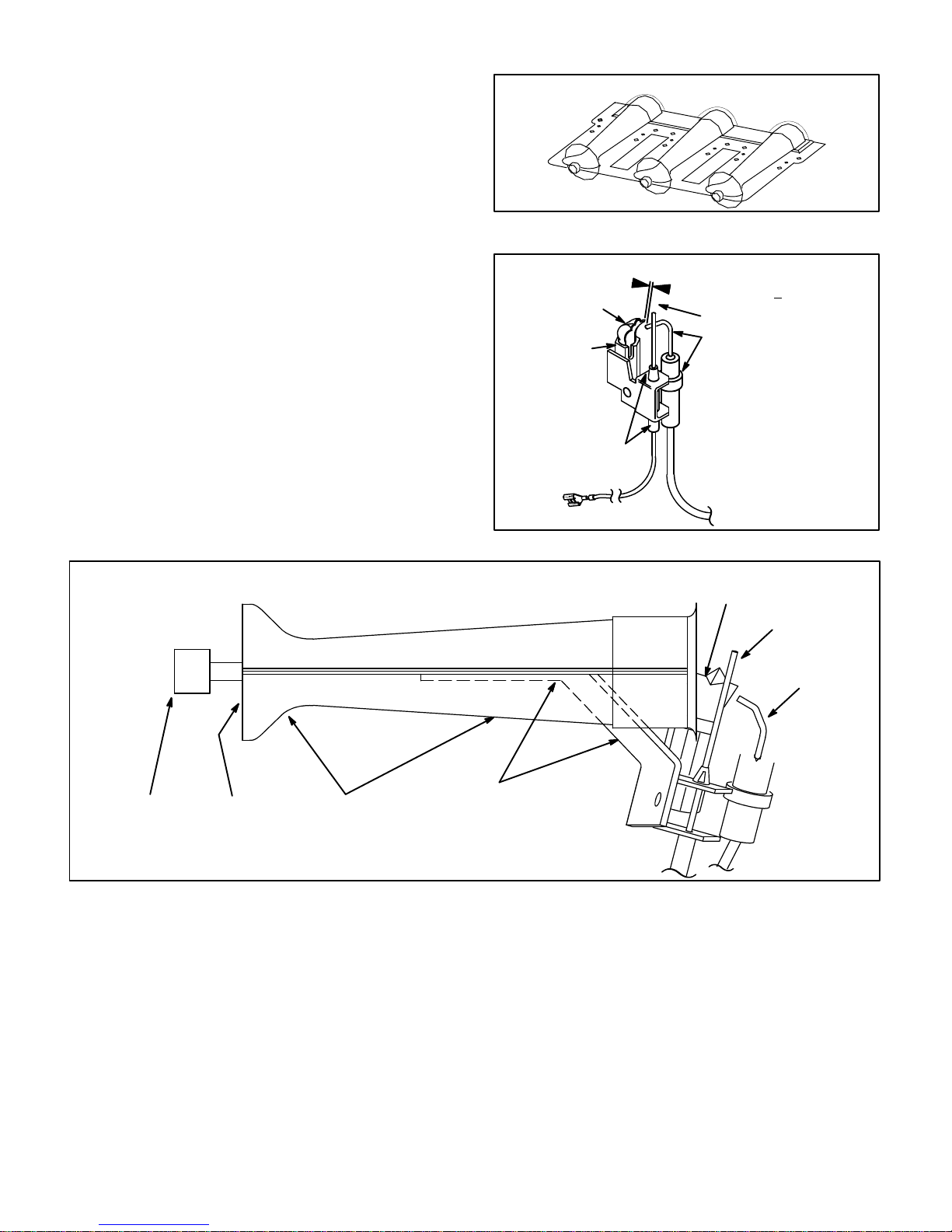
H-Pilot, Spark Electrode, Flame Sensor
and Burners (-1 Through -4 Models)
Figure 17 shows the arrangement of pilot, flame sensor,
spark electrode and burners. The ignition control uses direct spark to ignite the pilot. The pilot ignites the burners
and the burners cross-light. The flame sensor uses flame
rectification to sense ignition. The ignition control requires
that pilot flame must be sensed before the main gas valve
is allowed to open. Typically, a 2 to 4 second delay occurs
between the pilot ignition and the main valve opening.
Figure16showsthe gap between tip of the electrodesand
the burner surface. It is important that the gap be maintained for consistent ignition of pilot flame.
A flame retention ring in the end of each burner is used to
maintain correct flame length and shape and to keep the
flamefrom lifting offthe burner head. In addition, the burner entrance to each clamshell (Figure 3) is fitted with a
flamebaffle or corbel toenhance the combustion process.
G23(X)-1, -2, -3 AND -4 MODELS BURNER PILOT/ELECTRODE
ORIENTATION
view looking at side of burners
TYPICAL BURNER ASSEMBLY
FIGURE 15
PILOT, SPARK ELECTRODE AND FLAME SENSOR
PILOT HOOD
PILOT
FLAME SENSOR
SENSE WIRE
1/8 (.125) Inch + ”1/32 (.031)
GAP
SPARKELECTRODE
SPARKWIRE
FIGURE 16
PILOT HOOD
FLAME SENSOR
ORIFICE
RETAINER
PRIMARY
AIR INLET
BURNER
SPARK
ELECTRODE
PILOT MOUNTING
BRACKET
FIGURE 17
Page 14
Page 15
127( 7KH *; IXUQDFH FRQWDLQ
V HOHFWURQLF FRP
SRQHQWV WKDW DUH SRODULW\ VHQVLWLYH 0DNH VXUH WKDW WKH
IXUQDFH LV ZLUHG FRUUHFWO\ DQG LV SURSHUO\ JURXQGHG
DANGER
Shock hazard.
Disconnect power before servicing. Control is not
field repairable. If control is inoperable, simply
replace entire control.
Can cause injury or death. Unsafe operation will
result if repair is attempted.
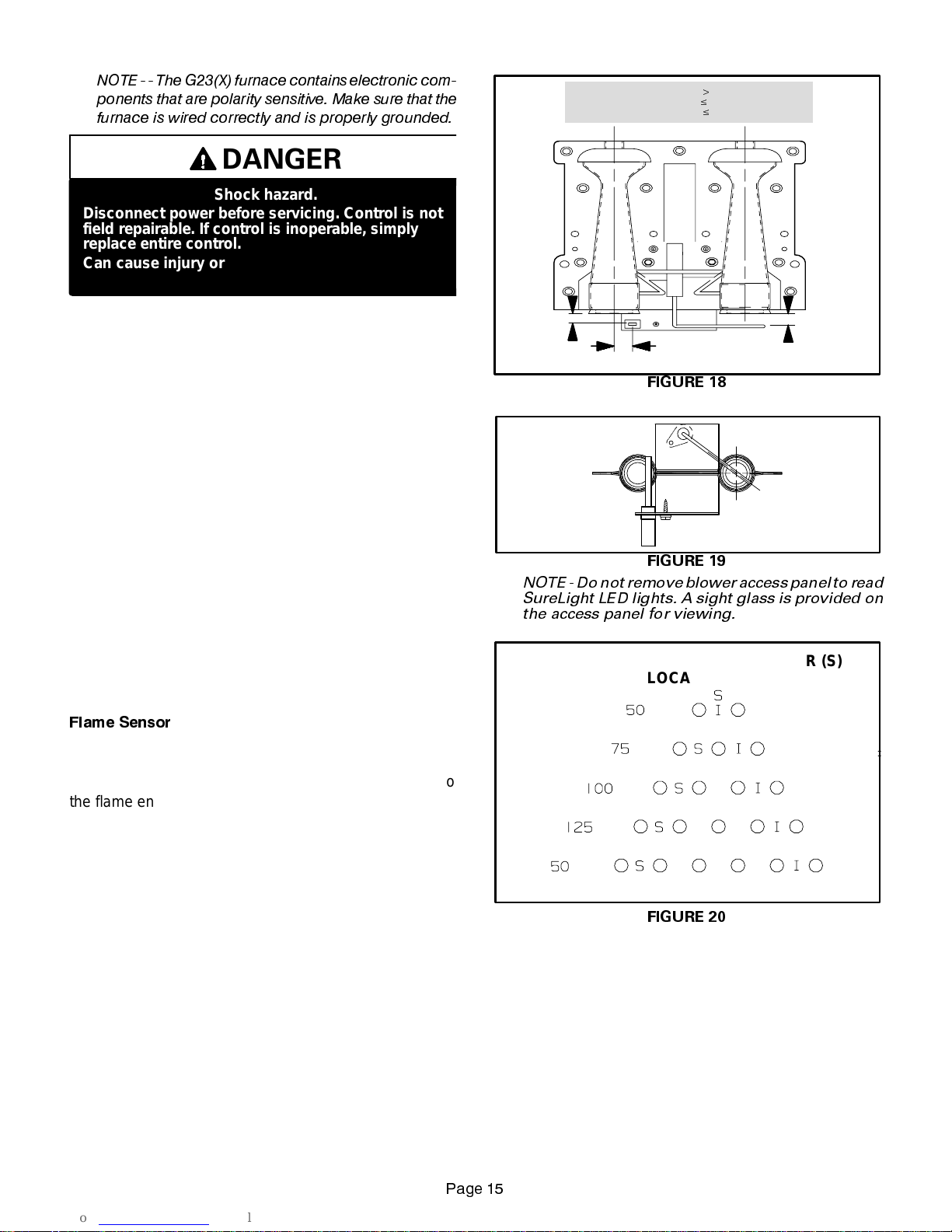
I- SureLight Ignition System A3
(-5 and -6 models)
All G23(X)-5 and -6 model units are equipped with the
Lennox SureLight ignition system. The system consists
of ignition control board (figure 21 with control terminal
designationsintable5)and ignitor(figures 18,19and20.
The board and ignitor work in combination to ensure furnace ignition and ignitor durability. The SureLight integrated board controls all major furnace operations. The
board also features two LED lights for troubleshooting
and two accessory terminals rated at (4) four amps. See
table6 for troubleshooting diagnostic codes. Table7and
8 show jack plug terminal designations. Units equipped
withtheSureLightboardcanbeusedwitheitherelectronic or electro-mechanical thermostats without modification. The SureLight ignitor is made of durable silic on-nitride. Ignitor longevity isalso enhanced by voltage ramping by the control board. The board finds the lowest ignitor temperature which will succes s fully light the burner,
thus increasing the life of t he ignitor.
NORMAL FLAME SIGNAL0.7 MICROAMPS
1/4”
IGNITOR
LOW FLAME SIGNAL
MINIMUM FLAME SIGNAL$0.15 MICROAMPS
19/64”
$
0.7 MICROAMPS
SENSOR
3/8”
FIGURE 18
SENSOR
IGNITOR
FIGURE 19
NOTE -Donotremove blower access panel to read
SureLight LED lights. A sight glass is provided on
the access panel for viewing.
SURELIGHT IGNITOR (I) AND SENSOR (S)
LOCATION
)ODPH 6HQVRU
Aflamesensorislocatedontheleftside of the burner support. See figures 18,19and 20. The sensoris mounted on
a bracket in the burner support and the tip protrudes into
the flame envelope of the left-most burner. The sensor is
fastened to burner supports and can be removed for service without removing any part of the burners. During operation, flame is sensed by current passed through the
flameandsensingelectrode.TheSureLightcontrolallows
the gas valve to remain open as long as flame signal is
sensed.
FIGURE 20
3DJH
Page 16
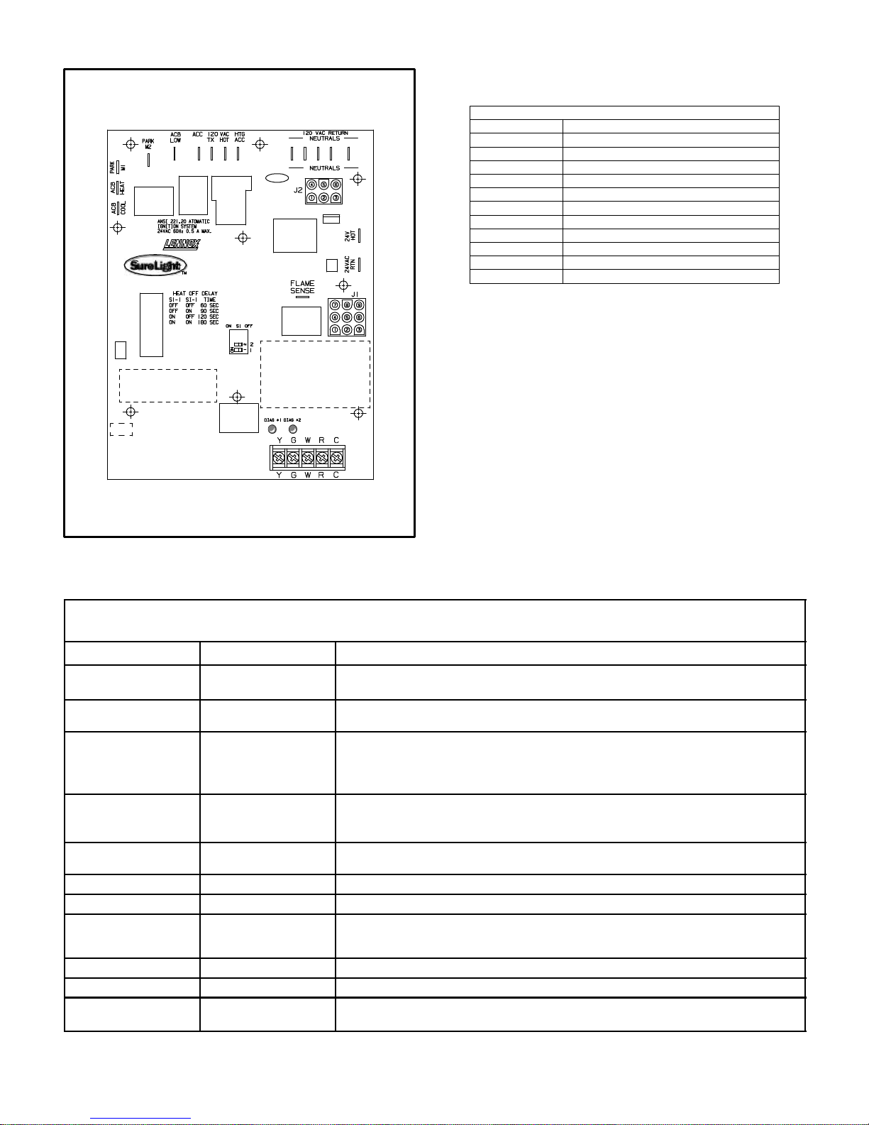
SURELIGHT CONTROL BOARD
TABLE 5
SURELIGHT CONTROL TERMINAL DESIGNATIONS
ACB COOL
ACB HEAT
PARK
ACB LOW
ACC
TX
HOT
HTG ACC
NEUTRALS
24VACHOT
24VACRTN
FLAME SENSE
Blower - Cooling Speed (Line Volt)
Blower - Heating Speed (Line Volt)
Alternate Blower Speeds (Dead)
Continuous Low Speed Blower
Accessory Terminal (Line Volt)
120VACHot to Transformer
120VACHot Input
Heat Only Accessory (Line Volt)
120VACNeutrals
24VACHot from Transformer
24VACReturn from Transformer
Flame Sense Terminal
FIGURE 21
TABLE 6
DIAGNOSTIC CODES
MAKE SURE TO ID LED’S CORRECTLY: REFER TO INSTALLATION INSTRUCTIONS FOR CONTROL BOARD LAYOUT.
LED #1 LED #2 DESCRIPTION
SIMULTANEOUS
SLOW FLASH
SIMULTANEOUS FAST
FLASH
SLOW FLASH ON
OFF SLOW FLASH
ALTERNATING SLOW
FLASH
SLOW FLASH OFF
ON SLOW FLASH
ON
ON
OFF
FAST FLASH SLOW FLASH
SLOW FLASH FAST FLASH
ALTERNATING FAST
FLASH
SIMULTANEOUS
SLOW FLASH
SIMULTANEOUS FAST
ALTERNATING SLOW
ALTERNATING FAST
FLASH
FLASH
ON
OFF
ON
FLASH
Also signaled during cooling and continues fan.
Normal operation - signaled when heating demand initiated at thermostat.
Primary or Secondary limit open. Units with board 63K8901 or 24L85: Limit must
close within 5 trials for ignition or board goes into one hour limit Watchguard.
Units with board 56L83 or 97L48: Limit must close within 3 minutes or board
Pressure switch open or has opened 5 times during a single call for heat; OR:
Blocked inlet/exhaust vent; OR: Condensate line blocked; OR: Pressure switch
closed prior to activation of combustion air blower.
Flame sensed without gas valve energized.
Rollout switch open. OR: 9 pin connector improperly attached.
Circuit board failure or control wired incorrectly.
Main power polarity reversed. Switch line and neutral.
Low flame signal. Measures below .7 microAmps. Replace flame sense rod.
Improper main ground or line voltage below 75 volts; OR: Broken ignitor; OR:
Power - Normal operation
goes into one hour limit Watchguard.
Watchguard - burners fail to ignite.
Open ignitor circuit.
NOTE - Slowflash equals1 Hz (oneflash persecond). Fast flashequals 3Hz (threeflashes per second).Drop out flamesense current< 0.15microAmps
Page 16
Page 17

TABLE 7
SureLight BOARD J156 (J2) TERMINAL
PIN # FUNCTION
1 Ignitor
2
3
4
5
6
DESIGNATIONS
Not Used
Ignitor Neutral
Combustion Air Blower Line Voltage
Not Used
Combustion Air Blower Neutral
TABLE 8
SureLight BOARD J58 (J1) TERMINAL
PIN # FUNCTION
1 Primary Limit In
2
3
4
5
6
7
8
9
DESIGNATIONS
Gas Valve Common
Roll Out Switch Out
Gas Valve 24V
Pressure Switch In
Pressure Switch and Primary Limit Out
Not Used
Roll Out Switch In
Ground
ELECTROSTATIC DISCHARGE (ESD)
Precautions and Procedures
CAUTION
Electrostatic discharge can affect electronic
components. Take precautions during furnace
installation and service to protect the furnace’s
electronic controls. Precautions will help to
avoid control exposure to electrostatic discharge by putting the furnace, the control and
the technician at the same electrostatic potential. Neutralize electrostatic charge by touching
hand and all tools on an unpainted unit surface,
such as thegas valve or blower deck, before performing any service procedure.
a-Electronic Ignition
On a call for heat the SureLight control monitors the combustionair blower pressureswitch. The control will notbegin the heating cycle if the pressure switch is closed (bypassed). Once the pressure switch is determined to be
open, the combustion air blower is energized. When the
differential in the pressure switch is great enough, the
pressure switch closes and a 15-second pre-purge begins. If the pressure switch is not proven within 2-1/2 minutes, the control goes into Watchguard-Pressure Switch
mode for a 5-minute re-set period.
After the 15-second pre-purge period, the SureLight ignitor warms up for 20 seconds after which the gas valve
opens for a 4-second trial for ignition. G23X units
equipped with board 24L85, 56L83 or 63K89: the ignitor
stays energized for the first second of the 4-second trial.
Units equipped with board 97L48: ignitor stays energized
duringthetrialuntilflameissensed.If ignition is not proved
during the 4-second period, the control will try four more
times with an inter purge and warm-up time between trials
of 35 seconds. After a total of five trials for ignition (including the initial trial), the control goes into WatchguardFlame Failure mode. After a 60-minute reset period, the
control will begin the ignition sequence again.
The SureLight control board has an added feature that
prolongs the life of the ignitor. After a successful ignition,
theSureLightcontrolutilizeslesspowertoenergize the ignitoron successive callsfor heat. Thecontrol continues to
rampdown the voltage tothe ignitor until itfinds the lowest
amount of power that will provide a successful ignition. It
finds this by ramping down until the ignitor will not light,
then steps up the amount of power by three times. This
amount of power is used for 255 cycles. On the 256th call
for heat, the control will again ramp down until the lowest
power is determined and the cycle begins again.
b-Fan Time Control
The fan on time of 45 seconds is not adjustable. Fan off
time (time that the blower operates after the heat demand
has been satisfied) can be adjusted by flipping the dip
switches located on the SureLight integrated control. The
unit is shipped with a factory fan off setting of 90 seconds.
Fan off time will affect comfort and is adjustable to satisfy
individual applications. See figure 22.
FAN-OFF TIME ADJUSTMENT
60sec. 90sec. 120sec. 180sec.
To adjust fan-off timing, flip dip switch to desired setting.
FIGURE 22
Page 17
Page 18

J-Gas Valve
TheG23(X) usesa gas valvemanufacturedbyHoneywell
or White Rodgers. See figure 23. The valve is internally
redundant to assure safety shut-off. If the gas valve must
be replaced, the same type valve must be used.
24VAC terminals and gas control knob are located on top of
the valve. All terminals on the gas valve are connected to
wires from the ignition control. 24V applied to the “PV” terminals opens the pilot (-1 through -4 models)and 24V appliedto
the “MV” terminals opens the valve on G23X. Inlet and outlet
pressure taps are located on the valve. A regulator adjustment screw (figure 24) is located on the valve.
An LPG changeover kit is available from Lennox. The kit includes main and pilot burner orifices, burner corbel plate (Nox
only), and regulator conversion kit.
K-Combustion Air Blower Prove
(Pressure) Switch (S64)
G23(X) series units are equipped with a combustion air
(pressure) switch located on the vestibule panel. The switch
is connected tothe combustion airblower housing by means
of a flexible silicon hose. It monitors air pressure in the combustion air blower housing. The other side of the pressure
switch is open to atmosphere.
The switch is a single-pole single-throw pressure switch
electrically connected in series with the ignition control. The
purpose of the switch is to prevent burner operation if the
combustion air blower is not operating.
On start-up, the switch senses that the combustion air blower is operating. It closes a circuit to the ignition control when
pressure inside the combustion air blower increases above
the setpoint. The setpoint is measured in negative inches
water gauge. The pressure sensed by the switch is relative
to atmospheric pressure. If the flue becomes obstructed during operation, the switch senses a loss of negative pressure
(drops below setpoint) and opens the circuit to the ignition
control .
The switch setpoint varies with unit model number. Look
for the setpoint printed on the side of the switch.
The switch is factory set and is not field adjustable. It is a
safety shut-down control in the furnace and must not be
bypassed for any reason.
HONEYWELL VR8204 SERIES GASVALVE
INLET
GAS VALVE SHOWN IN OFF POSITION
21
2))
WHITE RODGERS
36E GAS VA
LVE
INLET
GAS VALVE
SHOWN
IN OFF
POSITION
FIGURE 23
WHITE RODGERS 36E GAS VALVE
REGULATOR ADJUSTMENT SCREW LOCATION
REGULATOR
COVER
SCREW
$'-867,1*
6&5(:
:KLWH
635,1*
HONEYWELL VR8204 GAS VALVE
REGULATOR ADJUSTMENT SCREW LOCATION
&$3 6&5(:
%ODFN
$'-867,1* 6&5(:
:KLWH
35(6685(
5(*8/$725
635,1*
5HG
,1/(7
35(6685(
7$3
*$6 ,1/(7
FIGURE 24
3DJH
Page 19

II-PLACEMENT AND INSTALLATION
Make sure unit is installed in accordance with installation
instructions and applicable codes.
A-Fresh Air Requirements
Until recently, there was no problem in bringing in sufficient
amounts of outdoor air for combustion -- infiltration provided
all the air that was needed and then some. In today’s homes
built with energy conservation in mind, tight construction practices make it necessary to bring in air from outside for combustion. Consideration must also be given to the use of exhaust fans, appliance vents, chimneys and fireplaces because they draw additionalair that could be used for combustion out of the house. Unless outside air is brought into the
home for combustion, negative pressure (pressure outside is
greater than inside pressure) will build to the pointthat a down
draft can occur in the furnace vent pipe or chimney . Combustion gases can enter the living space creating a potentially
dangerous situation.
Theimportanceofthe previous paragraphcannotbeoverstated. Users may inadvertently block fresh air intakes after installation.
In the absence of local codes concerning air for combustion
and ventilation, the following section outlines guidelines and
recommends procedures for operating G23(X) furnaces in a
manner that ensures efficient and safe operation. Special
consideration must be given to combustion air needs as well
as requirements for exhaust vents and gas piping. A portion
of this information has been reprinted with permission from
the National Fuel Gas Code (ANSI-Z223.1). This reprinted
material is not the complete and official position of the ANSI
on the referenced subject, which is represented only by the
standard in its entirety .
In Canada, refer to the standard CAN/CGA-B149.1 and B149.2 installation codes.
Combustion Air Requirements
&$87,21
Insufficient combustion air can cause headaches,
nausea, dizziness or asphyxiation. Excessive exposure to contaminated combustion air will result
in safety and performance related problems.
Avoidexposuretothe following substances in the
combustion air supply:
Permanent wave solutions;
Chlorinated waxes and cleaners;
Chlorine base swimming pool chemicals;
Water softening chemicals;
De-icing salts or chemicals;
Carbon tetrachloride;
Halogen type refrigerants;
Cleaning solvents (such as perchloroethylene);
Printing inks, paint removers, varnishes, etc.;
Hydrochloric acid;
Cements and glues;
Antistatic fabric softeners for clothes dryers; and
Masonry acid washing materials.
All gas-fired appliances require air to be used for the combustion process. If sufficient amounts of combustion air are
not available, the furnace or other appliance will operate in
an inefficient and unsafe manner . Enough air must be provided to meet the needs of all fuel-burning appliances, as
well as appliances such as exhaust fans which force air out
of the home. When fireplaces, exhaust fans, or clothes dryers are used at the same time as the furnace,much more air
is required to ensure proper combustion and to prevent a
down-draft situation. Insufficient amounts of air also cause
incomplete combustion which can result in carbon monoxide. The requirements for providing air for combustion and
ventilationdepend largely onwhether the furnace is installed
in an unconfined or confined space.
Unconfined Space
An unconfined space is an area such as a basement or
largeequipmentroomwithavolumegreaterthan 50cubic
feetper 1,000 Btu per hour of thecombined input rating of
all appliances installed in that space. This space also includesadjacent rooms which are not separated by adoor.
Though an area may appear to be unconfined, it might be
necessary to bring in outdoor air for combustion if the
structure does not provide enough air by infiltration. If the
furnace is located in a building of tight construction with
weather stripping and caulking around the windows and
doors,followthe procedures outlined for using air fromthe
outside for combustion and ventilation.
Confined Space
A confined space is an area with volume less than 50 cubic
feetper 1,000 Btu per hour of the combined input rating of all
appliances installed in that space. This definition includes
furnace closets or small equipment rooms.
3DJH
Page 20

Whenthefurnace is installed sothatsupplyducts carryair
circulated by the furnace to areas outside the space containingthefurnace,thereturnairmustbehandledbyducts
which are sealed to the furnace casing and which terminate outside the space containing the furnace. This is especially important when the furnace is mounted on a platform in a confined space such as a closet or small equipment room. Even a small leak around the base of the unit
at the platform or at the return air duct connection can
cause a potentially dangerous negative pressure condition.Airforcombustion and ventilation can be brought into
the confined space either from inside the building or from
outside.
Air from Inside
If the confined space housing the furnace adjoins space
categorizedasunconfined,air canbebroughtinbyprovid-
Air from Outside
Ifair from outsideis brought in forcombustion and ventilation,theconfined space shallbeprovidedwithtwo permanent openings. One opening shall be within 12 inches of
the top of the enclosure and one within 12 inches of the
bottom. These openings must communicate directly or by
ductswiththeoutdoorsorspaces(crawlor attic) thatfreely
communicate with the outdoors or indirectly through verticalducts.Eachopeningshallhaveaminimumfreeareaof
1square inch per 4,000Btu per hour of totalinput rating of
all equipment in the enclosure (See figures 26 and 27).
When communicating with the outdoors through horizontalducts, each opening shall have a minimumfree areaof
1 square inch per 2,000 Btu per total input rating of all
equipment in the enclosure (See figure 28).
EQUIPMENT IN CONFINED SPACE
ALL AIR FROM OUTSIDE
(Inlet Air from Crawl Space and
CHIMNEY
OR GAS
VENT
Outlet Air to Ventilated Attic)
VENTILATION LOUVERS
(Each end of attic)
ing two permanent openings between the two spaces.
Eachopening must have aminimum free areaof 1 square
inch per 1,000 Btu per hour of the total input rating of all
gas-fired equipment in the confined space. Each opening
must be at least 100 square inches. One opening shall be
within12 inchesof the top of the enclosure and one opening within 12 inches of the bottom (See figure 25).
EQUIPMENT IN CONFINED SPACE
ALL AIR FROM INSIDE
CHIMNEY OR
GAS VENT
WATER
G23(X)
FURNACE
HEATER
OPENINGS
(To Adjacent
Room)
G23
FURNACE
VENTILATION
LOUVERS
(For unheated
crawl space)
OUTLET
AIR
WATER
HEATER
INLET
AIR
NOTE-The inlet and outlet air openings shall each have a free
area of at least one square inch per 4,000 Btu per hour of the
total input rating of all equipment in the enclosure.
FIGURE 26
EQUIPMENT IN CONFINED SPACE
CHIMNEY
OR GAS
VENT
G23(X)
FURNACE
ALL AIR FROM OUTSIDE
(All Air Through Ventilated Attic)
VENTILATION LOUVERS
(Each end of attic)
OUTLET
AIR
INLET AIR
(Ends 12 above
bottom)
NOTE-Each openingshall have a free areaof at least one square
inch per 1,000 Btu per hour of the total input rating of all equip-
ment in the enclosure, but not less than 100 square inches.
FIGURE 25
3DJH
WATER
HEATER
NOTE-The inlet and outlet air openings shall each have a free
area of at least one square inch per 4,000 Btu per hour of the
total input rating of all equipment in the enclosure.
FIGURE 27
Page 21

EQUIPMENT IN CONFINED SPACE
ALL AIR FROM OUTSIDE
CHIMNEY
OR GAS
VENT
WATER
HEATER
OUTLET AIR
G23(X)
FURNACE
INLET AIR
NOTE-Each air duct opening shall have a free area of at least
one square inch per 2,000 Btu per hour of the total input rating
of all equipment in the enclosure. If the equipment room is lo-
cated against an outside wall and the air openings communi-
cate directly with the outdoors, each opening shall have a free
area of at least one square inch per 4,000 Btu per hour of the
total input rating of all other equipment in the enclosure.
FIGURE 28
When ducts are used, they shall be of the same cross-sectional area as the free area of the openings to which they
connect. The minimum dimension of rectangular air ducts
shall be no less than 3 inches. In calculating free area, the
blocking effect of louvers, grilles, or screens must be considered. If thedesign and freearea of protective covering is
not known for calculating the size opening required, it may
be assumed that wood louvers will have 20 to 25 percent
free area and metal louvers and grilles will have 60 to 75
percent free area. Louvers and grilles must be fixed in the
openpositionorinterlocked with the equipmentsothatthey
are opened automatically during equipment operation.
B-Flue Venting Requirements
G23(X)seriesfurnacesmustbeventedincompliancewith
all local codes, the venting tables provided in this manual
and these instructions.
The G23(X) series units have been classified as fan assisted Category I type furnaces when vertically vented in
accordance with the latest edition of ANSI Z21.47 Central
Furnace Standard. The definition of a fan assisted Category I type furnace is an appliance equipped with an integral
mechanical means to either draw or force products of combustion through the combustion chamber and/or heat exchanger.
The vent sizing tables in this manual have been extracted
fromtheNationalFuelGasCode(NFPA54/ANSI Z223.1)
and are provided for convenience to serve as a guideline
for proper vent installation. Proper application, termination,constructionandlocationofvents must conform to local codes having jurisdiction. In the absence of local
codes, the NFGC serves as the defining document.
Referto the tables and the venting information contained in
these instructions for proper sizing and installation of the
venting system.
The G23(X) series units have the following flue collar
sizes: -50 unit, 3” diameter; -75 and -100 units, 4” diameter; and -125 & -150 units, 5” diameter. Use this informationinconjunctionwiththe providedventingtablestoproperlysizetheventorventconnectorthatattaches to thefurnace flue collar.
Venting Using a Masonry Chimney
The following additional requirements apply when a lined
masonry chimney is beingused to vent a G23(X) furnace:
A Category I appliance must never be connected to a
chimney that is servicing a solid fuel appliance. If a fireplace chimney flue is used to vent this appliance, the fireplace opening must be permanently sealed.
3DJH
Page 22

COMMON VENTING USING TILE-LINED INTERIOR MASONRY
CHIMNEY AND COMBINED VENT CONNECTOR
MINI. LENGTH = AS SHORT
AS PRACTICAL.
OTHER
APPLIANCE
G23
FIGURE 29
A chimney with one or more sides exposed to the outside
of the structure is considered to be an exterior chimney.A
TypeBorlistedchimneyliningsystempassingthroughan
unused masonry chimney flue is not considered to be exposed to the outdoors.
Masonry chimneys used to vent Category I central furnaces must be either tile-lined or lined with a listed metal
lining system or dedicated gas vent. Unlined masonry
chimneys are prohibited.
A fan assisted furnace may be commonly vented into an
existing lined internal masonry chimney provided:
1 - The chimney is currently serving at least one draft-
hood equipped appliance.
2 - The vent connectors and chimneyare sized in accor-
dance with the provided venting tables.
SINGLE
APPLIANCE VENTING OF A FAN ASSISTED
FURNACE INTO A TILE-LINED MASONRY CHIMNEY
(INTERIOR OR OUTSIDE WALL) IS
PROHIBITED
.THE
CHIMNEY MUST FIRST BE LINED WITH EITHER TYPE
“B” VENT OR AN INSULATEDSINGLE WALL FLEXIBLE
VENTLININGSYSTEM,SIZEDIN ACCORDANCE WITH
THE PROVIDED VENTING TABLES.
See figures 29 and 30 for common venting.
A Type “B” vent or masonry chimney liner shall terminate
above the roof surface with a listed cap or a listed roof assembly in accordance with the terms of their respective
listings and the vent manufacturer’s instructions.
Donotinstallamanualdamper,barometricdraftregulator,
or flue restrictor between the furnace and the chimney.
INTERIOR
TILE-LINED MASONRY
CHIMNEY
NOTE - CHIMNEY MUST BE
PROPERLY SIZED PER THE PRO-
VIDED VENTING TABLES OR LINED
WITH LISTED METAL LINING SYSTEM.
VENT
CONNECTOR
(Double-walled,
single-walled, or
insulated single-
walled pipe)
PERMANENTLY SEALED
FIREPLACE OPENING
If type “B” double-wall vent is used inside a chimney, no
otherappliancecanbeventedintothechimney. Outer wall
oftype “B” vent pipe mustnot be exposed toflueproducts.
Insulation for the flexible vent pipe must be an encapsulated fiberglass sleeve recommended by the flexible vent
pipe manufacturer. See figure 30.
The space between liner and chimney wall should
NOT be insulated with puffed mica or any other loose
granular insulating material.
COMMON VENTING USING
METAL-LINED MASONRY CHIMNEY
SEALED
MIN. LENGTH -- AS
5FT.
(1.5m)
MINIMUM
4 IN. MIN.
(102mm)
SHORT AS PRACTICAL
PERMANENTLY
SEALED FIREPLACE
CHIMNEY WITH
FLEXIBLE VENT
OPENING
EXTERIOR
“B” VENT OR
INSULATED
FIGURE 30
PIPE.
3DJH
Page 23

If“B”ventoraninsulatedflexiblevent pipe cannot be used
as liners, the chimney must be rebuilt to accommodate
oneofthesemethodsorsomealternateapprovedmethod
must be found to vent the appliance.
When inspection reveals that an existing chimney is not
safefor the intended purpose, itshall be rebuilt toconform
to nationally recognized standards, lined or relined with
suitable materials or replaced with a gas vent or chimney
suitableforventingG23(X)series units. The chimney passageway must be checked periodically to ensure that it is
clear and free of obstructions.
General Venting Requirements
All G23(X) furnaces must be vented in accordance with
the methods outlined in these instructions.
1 - Vent diameter recommendations and maximum runs
allowed are found in the provided venting tables.
2 - In no case should the vent or vent connector diameter
be less than the diameter specified in the provided
venting tables.
3-
For single appliance vents:
If the vertical vent or tilelinedchimney has a larger diameter or flow area than
theventconnector,usethe
determinethe
minimum vent capacity
verticalventdiameter
andthe vent
to
connector diameter to determine the maximum
ventcapacity. Theflowareaoftheverticalvent,how-
ever, shall not exceed 7 times the flow area of the
listedappliancecategorizedventarea,drafthoodoutlet area or flue collar area unless designed in accordance with approved engineering methods.
4-
For multiple appliance vents:
The flow area of the
largestsectionofverticalventorchimneyshallnotexceed 7 times the smallest listed appliance categorized vent area, flue collar area or drafthood outlet
area unless designed in accordance with approved
engineering methods.
5 - The entire length of single wall metal vent connector
shall be readily accessible for inspection, cleaning,
and replacement.
6 - Single appliance venting configurations with zero lat-
eral lengths, see tables 9 and 10, are assumed to
have no elbowsin the vent system.For all other vent
configurations, the vent system is assumed to have
two 90Eelbows. For each additional 90Eelbow or
equivalent (for example two 45Eelbows equal one
90Eelbow) beyond two, the maximum capacity listed
in the venting table should be reduced by 10 percent
(0.90 x maximum listed capacity).
7 - The common venting tables 11, 12, 13, and 14 were
generated using a maximum horizontal vent connector length of 1-1/2 feet (18 inches) for each inch of
connector diameter as follows:
CONNECTOR
DIAMETER
(INCHES)
3 4-1/2
4 6
5 7-1/2
6 9
7 10-1/2
MAXIMUM HORIZONTAL
CONNECTOR LENGTH
(FEET)
8 - If the common vertical vent is offset, the maximum
common vent capacity listed in the common venting
tables should be reduced by 20%, the equivalent of
two 90Eelbows (0.80 x maximum common vent capacity).Thehorizontallength oftheoffsetshallnotexceed 1-1/2 feet for each inch of common vent diameter.
9 - The vent pipe should be as short as possible with
the leas t number of elbows and angles to do the
job. The vent connector should be routed to the vent
utilizing the shortest possible route.
10- A vent connector shall be supported without any dips
or sags and shall slope a minimum of 1/4” per linear
foot of connector, back towards the appliance.
11- Vent connectors shall be firmly attached to furnace
flue collars by sheet metal screws or other approved
means,exceptventconnectorsoflistedType“B”vent
material which shall be assembled in accordance
with the manufacturer’s instructions. Joints between
sections of single wall connector piping shall be fastened by sheet metal screws or other approved
means.
12- When the vent connector used for Category I ap-
pliances must be located in or pass through a crawl
space or other areas which may be cold, that portion
of the vent connector shall be listed double-wall Type
B vent material or material having equivalent insulation qualities.
13- All venting pipe passing through floors, walls, and
ceilings must be installed with the listed clearance to
combustible materials and be fire stopped according
to local codes. In absence of local codes, refer to
NFGC (Z223.1).
14- No portion of the venting system can extend into, or
pass through any circulation air duct or plenum.
15- Vent connectors serving Category I appliances shall
not be connected to any portion of mechanical draft
systems operation under positive pressure such as
Category III or IV venting systems.
16- If vent connectors are combined prior to entering the
common vent, the maximum common vent capacity
listed in the common venting tables must be reduced
by 10%, the equivalent of one 90Eelbow (0.90 x maximum common vent capacity).
17- Common vent diameter must always be at least as
large as the largest vent connector diameter.
3DJH
Page 24

18- In no case, shall the vent connector be upsized more
(feet)
(feet)
5
than two consecutive table size diameters over the
size of the drafthood outlet or flue collar outlet.
19- A manual damper, barometric draft regulator or flue
restrictor must not be installed between furnace and
any chimney.
20- When connecting this appliance to an existing dedi-
cated or common venting system, the venting system,
must be inspected for signs of corrosion, and general
condition. The sizing of the vent system must be reviewed and conform to these instructions and the provided venting tables. If the existing system is in conflict
with these requirements, the venting system must be
resized.
TABLE 9
CAPACITY OF TYPE B DOUBLE-WALL VENTS WITH TYPE B DOUBLE-WALL CONNECTORS
SERVING A SINGLE CATEGORY I APPLIANCE
Vent and Connector Diameter - D (inches)
Height
H
(feet)
6
8
10
15
20
30
NOTE: Singleappliance venting configurations with zerolateral lengths areassumed to haveno elbows inthe ventsystem. For allother vent configura-
tions,the ventsystem is assumedto havetwo 90
beyond two, the maximum capacity listed in the venting table should be reduced by 10 percent (0.90 x maximum listed capacity).
Lateral
L
(feet)
0 0 78 0 152 0 251 0 375
2 13 51 18 97 27 157 32 232
4 21 49 30 94 39 153 50 227
6 25 46 36 91 47 149 59 223
0 0 84 0 165 0 276 0 415
2 12 57 16 109 25 178 28 263
5 23 53 32 103 42 171 53 255
8 28 49 39 98 51 164 64 247
0 0 88 0 175 0 295 0 447
2 12 61 17 118 23 194 26 289
5 23 57 32 113 41 187 52 280
10 30 51 41 104 54 176 67 267
0 0 94 0 191 0 327 0 502
2 11 69 15 136 20 226 22 339
5 22 65 30 130 39 219 49 330
10 29 59 40 121 51 206 64 315
15 35 53 48 112 61 195 76 301
0 0 97 0 202 0 349 0 540
2 10 75 14 149 18 250 20 377
5 21 71 29 143 38 242 47 367
10 28 64 38 133 50 229 62 351
15 34 58 46 124 59 217 73 337
20 48 52 55 116 69 206 84 322
0 0 100 0 213 0 374 0 587
2 9 81 13 166 14 283 18 432
5 21 77 28 160 36 275 45 421
10 27 70 37 150 48 262 59 405
15 33 64 44 141 57 249 70 389
20 56 58 53 132 66 237 80 374
30 NR NR 73 113 88 214 104 346
3 Inch 4 Inch 5 Inch 6 Inch
Appliance Input Rating in Thousands of Btu Per Hour
MIN MAX MIN MAX MIN MAX MIN MAX
elbows.For eachadditional 90Eelbowor equivalent(for example two45Eelbowsequal one90Eelbow)
E
3DJH
Page 25

TABLE 10
(feet)
(feet)
5
30
CAPACITY OF TYPE B DOUBLE-WALL VENTS WITH SINGLE-WALL METAL CONNECTORS
SERVING A SINGLE CATEGORY I APPLIANCE
Vent and Connector Diameter - D (inches)
Height
H
(feet)
6
8
10
15
20
30
NOTE: Singleappliance venting configurations with zerolateral lengths areassumed to haveno elbows inthe ventsystem. For allother vent configura-
tions,the ventsystem is assumedto havetwo 90
beyond two, the maximum capacity listed in the venting table should be reduced by 10 percent (0.90 x maximum listed capacity).
Lateral
L
(feet)
0 38 77 59 151 85 249 126 373
2 39 51 60 96 85 156 123 231
4 NR NR 74 92 102 152 146 225
6 NR NR 83 89 114 147 163 220
0 37 83 58 164 83 273 123 412
2 39 56 59 108 83 176 121 261
5 NR NR 77 102 107 168 151 252
8 NR NR 90 95 122 161 175 243
0 37 87 57 174 82 293 120 444
2 39 61 59 117 82 193 119 287
5 52 56 76 111 105 185 148 277
10 NR NR 97 100 132 171 188 261
0 36 93 56 190 80 325 116 499
2 38 69 57 136 80 225 115 337
5 51 63 75 128 102 216 144 326
10 NR NR 95 116 128 201 182 308
15 NR NR NR NR 158 186 220 290
0 35 96 54 200 78 346 114 537
2 37 74 56 148 78 248 113 375
5 50 68 73 140 100 239 141 363
10 NR NR 93 129 125 223 177 344
15 NR NR NR NR 155 208 216 325
20 NR NR NR NR 186 192 254 306
0 34 99 53 211 76 372 110 584
2 37 80 55 164 76 281 109 429
5 49 74 72 157 98 271 136 417
10 NR NR 91 144 122 255 171 397
15 NR NR 115 131 151 239 208 377
20 NR NR NR NR 181 223 246 357
30 NR NR NR NR NR NR NR NR
3 Inch 4 Inch 5 Inch 6 Inch
Appliance Input Rating in Thousands of Btu Per Hour
MIN MAX MIN MAX MIN MAX MIN MAX
elbows.For eachadditional 90Eelbowor equivalent(for example two45Eelbowsequal one90Eelbow)
E
3DJH
Page 26

TABLE 11
Vent
C
Height
Rise
6
0
5
30
V
g
Height
CAPACITY OF TYPE B DOUBLE-WALL VENTS WITH TYPE B DOUBLE-WALL CONNECTORS
SERVING TWO OR MORE CATEGORY I APPLIANCES
VENT CONNECTOR CAPACITY
Height
H
(feet) (feet)
6
8
10
15
20
30
onnector
Rise
3 Inch 4 Inch 5 Inch 6 Inch
R
MIN MAX MIN MAX MIN MAX MIN MAX
1 22 37 35 66 46 106 58 164
2 23 41 37 75 48 121 60 183
3 24 44 38 81 49 132 62 199
1 22 40 35 72 49 114 64 176
2 23 44 36 80 51 128 66 195
3 24 47 37 87 53 139 67 210
1 22 43 34 78 49 123 65 189
2 23 47 36 86 51 136 67 206
3 24 50 37 92 52 146 69 220
1 21 50 33 89 47 142 64 220
2 22 53 35 96 49 153 66 235
3 24 55 36 102 51 163 68 248
1 21 54 33 99 46 157 62 246
2 22 57 34 105 48 167 64 259
3 23 60 35 110 50 176 66 271
1 20 62 31 113 45 181 60 288
2 21 64 33 118 47 190 62 299
3 22 66 34 123 48 198 64 309
Vent and Connector Diameter - D (inches)
Appliance Input Rating in Thousands of Btu Per Hour
TABLE 12
CAPACITY OF TYPE B DOUBLE-WALL VENTS WITH TYPE B DOUBLE-WALL CONNECTORS
SERVING TWO OR MORE CATEGORY I APPLIANCES
COMMON VENT CAPACITY
ent
ht
Hei
H
(feet)
6 92 81 140 116 204 161 309 248
8 101 90 155 129 224 178 339 275
10 110 97 169 141 243 194 367 299
15 125 112 195 164 283 228 427 352
20 136 123 215 183 314 255 475 394
30 152 138 244 210 361 297 547 459
FAN + FAN FAN + NAT FAN + FAN FAN + NAT FAN + FAN FAN + NAT FAN + FAN FAN + NAT
4 Inch 5 Inch 6 Inch 7 Inch
Appliance Input Rating in Thousands of Btu Per Hour
Common Vent Diameter - D (inches)
3DJH
Page 27

TABLE 13
g
C
Height
Rise
6
30
V
g
Height
CAPACITY OF TYPE B DOUBLE-WALL VENT WITH SINGLE-WALL METAL CONNECTORS
SERVING TWO OR MORE CATEGORY I APPLIANCES
VENT CONNECTOR CAPACITY
Vent
ht
Hei
H
(feet) (feet)
6
15
30
onnector
Rise
3 Inch 4 Inch 5 Inch 6 Inch
R
MIN MAX MIN MAX MIN MAX MIN MAX
1 NR NR NR NR NR NR NR NR
2 NR NR NR NR NR NR 168 182
3 NR NR NR NR 121 131 174 198
1 NR NR 79 87 116 138 177 214
2 NR NR 83 94 121 150 185 230
3 NR NR 87 100 127 160 193 243
1 47 60 77 110 113 175 169 278
2 50 62 81 115 117 185 177 290
3 54 64 85 119 122 193 185 300
Vent and Connector Diameter - D (inches)
Appliance Input Rating in Thousands of Btu Per Hour
TABLE 14
CAPACITY OF TYPE B DOUBLE-WALL VENTS WITH SINGLE-WALL METAL CONNECTORS
SERVING TWO OR MORE CATEGORY I APPLIANCES
COMMON VENT CAPACITY
ent
ht
Hei
H
(feet)
6 89 78 136 113 200 158 304 244
8 98 87 151 126 218 173 331 269
10 106 94 163 137 237 189 357 292
15 121 108 189 159 275 221 416 343
20 131 118 208 177 305 247 463 383
30 145 132 236 202 350 286 533 446
FAN + FAN FAN + NAT FAN + FAN FAN + NAT FAN + FAN FAN + NAT FAN + FAN FAN + NAT
4 Inch 5 Inch 6 Inch 7 Inch
Appliance Input Rating in Thousands of Btu Per Hour
Common Vent Diameter - D (inches)
Removal of Unit from Common Venting System
In the event that an existing furnace is removed from a
venting system commonly run with separate gas appliances, the venting system is likely to be too large to
properly vent the remaining attached appliances. The followingtestshouldbeconducted whileeach appliance is in
operationandthe otherappliancesnotinoperationremain
connected to the common venting system. If the venting
systemhas been installed improperly,thesystemmustbe
corrected as outlined in the previous section.
1 - Seal any unused openings in the common venting
system.
2 - Visually inspect the venting system for proper size
and horizontal pitch and determine there is no blockage or restriction, leakage, corrosion and other deficiencies which could cause an unsafe condition.
3 - Insofar as is practical, close allbuilding doors and win-
dowsand all doors between the spaceinwhich the appliances remaining connected to the common venting
system are located and other spaces of the building.
Turn on clothes dryers and any appliances not connectedtothecommonventing system. Turnonanyex-
haust fans, such as range hoods and bathroom exhausts,so they will operate at maximum speed.Donot
operate a summer exhaust fan. Close fireplace dampers.
4 - Following the lighting instruction, place the appliance
being inspected in operation. Adjust thermostat so appliance will operate continuously.
5 - Testfor spillageatthedrafthoodreliefopeningafter5
minutes of main burner operation. Use the flame of a
match or candle, or smoke from a cigarette, cigar or
pipe.
6 - After it has been determined that each appliance re-
maining connected to the common venting system
properly vents when tested as outlined above, return
doors,windows,exhaustfans,fireplacedampersand
any other gas burning appliance to their previous
condition of use.
7 - If improper venting is observed during any of the
above tests, the common venting system must be
corrected.Thecommonventingsystemshouldberesizedtoapproachtheminimumsizeasdeterminedby
using the appropriate tables in appendix G in the current standards of the National Fuel Gas Code ANSI
Z223-1.
3DJH
Page 28

Horizontal Venting
SIDE WALL VENTING KIT WIRING
CK-43 CONTROL BOX
PRESSURE
SWITCH
C
NO
L1 MN
L1
120VAC
L2
2
1
354
RELAY
T1 T2 T3
SWG
POWER
M
VENTER
MOTOR
FIGURE 31
THERMOSTATCONNECTIONS
TERMINAL IN FURNACE
JUNCTION BOX
WR Y G
FACTORY INSTALLED WIRING
FIELD INSTALLED WIRING
T
G
R
W
Y
24 VAC
THERMOSTAT
WARNING
Donotusethis furnaceifanyparthas been underwater.Inspectthe furnace and replace any part of
thecontrolsystemand any gas control which has
been under water.
CAUTION
Beforeattemptingtoperformanyserviceormaintenance, turn the electrical power to unit OFF at
disconnect switch.
WARNING
If overheating occurs or if gas supply failsto shut
off,shut off the manual gas valve to the appliance
before shutting off electrical supply.
This furnace is design certified by the American Gas
Association for horizontal venting through an outside wall
only with the use of a Field Controls Company Model
SWG-4L side wall venting kit available from Lennox Dealer Service Center. No other Field brand venting kit or any
other manufacturer’s venting kit is acceptable. Horizontal
venting of this furnace without the use of the above stated
kit is prohibited. See figure 31 for field wiring of side wall
horizontal venting kit.
When horizontally vented, minimum clearance for termination from electric meters, gas meters, regulators and
relief equipment is 4 ft. (1.2m).
III-START-UP
A-Preliminary and Seasonal Checks
1 - Inspect electrical wiring, both field and factory installed
for loose connections. Tighten as required.
2 - Check voltage at disconnect switch. Voltage must be
withinrangelistedon thenameplate.Ifnot,consultthe
powercompany and have voltage conditioncorrected
before starting unit.
B-Heating Start-Up
FOR YOUR SAFETY READ BEFORE LIGHTING
WARNING
Shock and burn hazard.
G23(X)-1 through -4 model units are equipped with
an electronic spark ignition system. Do not attempt
to light manually.
BEFORE LIGHTING smell all around the appliance area
for gas. Be sure to smell next to the floor because some
gas is heavier than air and will settle on the floor.
Useonlyyour hand topushin or turn thegas control knob.
Neverusetools.Iftheknobwillnotpushinorturnbyhand,
do not try to repair it, call a qualified service technician.
Forceor attempted repair may result in afire or explosion.
G23(X) -1 through -4 model units are equipped with an intermittent pilot ignition system. Do not
attempt to manually light
pilot on these furnaces. Each time thermostat calls for heat,
the pilot will be automatically lit. The pilot does not burn when
there is no call for heat.
How To Operate Gas Valve (Figure 33)
WARNING
If you do not follow these instructions exactly, a
fire or explosion may result causing property
damage, personal injury or loss of life.
Gas Valve Operation (Figure 33)
1- STOP! Read the safety information at the beginning
of this section.
2 - Set thermostat to lowest setting. See figure 32.
3 - Turn off all electrical power to appliance.
THERMOSTATS
WARNING
Shock and burn hazard.
G23(X)-5 and -6 model units are equipped with the
SureLight ignition system. Do not attempt to light
manually..
FIGURE 32
3DJH
Page 29

4 - This appliance is equipped with an ignition device
which automatically lights the furnace. Do not try to
light the furnace by hand.
5 - Remove upper access panel.
6 - On Honeywell VR8204 gas valves, turn knob on gas
valve clockwise
to OFF. For White Rodgers 36E
gasvalves,moveswitchtoOFF.Donotforce.Seefig-
ure 33.
HONEYWELL VR8204 SERIES GASVALVE
21
2))
GAS VALVE SHOWN IN OFF POSITION
WHITE RODGERS
36E GAS VALVE
GAS VALVE
SHOWN
IN OFF
POSITION
FIGURE 33
7 - Wait five (5) minutes to clear out any gas. If you then
smell gas,
STOP
! Immediately call your gas supplier
from a neighbor’s phone. Follow the gas supplier’s
instructions. If you do not smell gas go to next step.
8 - For Honeywell VR8204 gas valves, turn knob on gas
valve counterclockwise
toON. For White Rodg-
ers 36E gas valves, move switch toON.
9 - Replace upper access panel.
10- Turn on all electrical power to unit.
11- Set thermostat to desired setting.
127(
:KHQ XQLW LV LQLWLDOO\ VWDUWHG VWHSV WKURXJK
PD\ QHHG WR EH UHSHDWHG WR SXUJH DLU IURP SLORW OLQH
12- Iftheappliancestillwillnotoperate,followtheinstruc-
tions “To Turn Off Gas To Unit” and call your service
technician or gas supplier.
C-Safety or Emergency Shutdown
Turn off unit power. Close manual and main gas
valves.
D-Extended Period S hutdown
Turnoffthermostatorsetto“UNOCCUPIED”mode.Close
allgasvalves(bothinternalandexternaltounit)toguarantee no gas leak into combustion chamber. Turn off power
tounit.All access panels,covers and vent caps must bein
place and secured.
IV-HEATING SYSTEM SERVICE CHECKS
A-A.G.A Certification
All units are A.G.A. design certified without modifications.
Refer to the G23(X) Operation and Installation Instruction
Manual Information.
B-Gas Piping
Gas supply piping should not allow more than
0.5W.C. drop in pressure between gas meter and
unit. Supply gas pipe must not be smaller than unit
gas connection. See table 16 for gas pipe capacity.
Compounds used on gas piping threaded joints should be
resistant to action of liquefied petroleum gases.
C-Testing Gas Piping
IMPORTANT
In case emergency shutdown is required, turn off
the main shut-off valve and disconnect the main
power to unit. These controls should be properly
labeled by the installer.
When pressure testing gas lines, the gas valve must be
disconnected and isolated. Gas valves can be damagedif
subjectedtomorethan 0.5psig(14”W.C.).Seefigure34
thepressureisequaltoor less than 0.5psig(14”W.C.),use
the manual shut-off valve before pressure testing to isolate furnace from gas supply.
GAS PIPING TEST PROCEDURE (Typical)
MANUAL MAIN
SHUT-OFF
VALVE
UNION
TEE
GAS VALVE
.
If
To Turn Off Gas To Unit
1 - Set thermostat to lowest setting.
2 - Turn off all electrical power to unit if service is to be
performed.
3 - Remove upper access panel.
4 - On Honeywell VR8204 gas valves, turn knob on gas
valve clockwise
to OFF. For White Rodgers 36E
gas valves, move switch to OFF. Do not force.
5 - Replace upper access panel.
3DJH
1/8” NPT
PLUGGED
TAP
CONDENSATE
TRAP
GAS VALVE WILL NOT HOLD
TEST PRESSURE IN EXCESS
OF 0.5 PSIG (14W.C.)
CAP
FIGURE 34
Page 30

MAIN SHUT-OFF
g
g
y
g
y
g
gaug
g
g
j
y
g
g
g
g
GROUND
JOINT
UNION
1/8” NPT
PLUGGED
TAP
RIGHT SIDE PIPING
AUTOMATIC
GAS VALVE
MANUAL
VALVE
AUTOMATIC
GAS VALVE
LEFT SIDE PIPING
(STANDARD)
MANUAL
MAIN SHUT-OFF
VALVE
GROUND
JOINT
UNION
1/8” NPT
PLUGGED
TAP
IMPORTANT
For safety, connect a shut-off valve between the
manometer and the gas tap to permit shut off o f
gas pressure to the manometer.
Unit (Fuel)
GAS VALVE REGULATION
Natural
L.P.
The gas valve is factory set and should not require ad-
justment. See table 15.
Manifold Adjustment Procedure:
1 - Connect a test gauge to outlet pressure tap on gas
valve. Start unit and allow 5 minutes for unit to reach
steady state.
2 - While waiting for the unit to stabilize, notice the flame.
Flame should be stable and should not lift from burner.
Natural gas should burn blue. L.P. gas should burn
mostly blue with some orange streaks.
3 - After allowing unit to stabilize for 5 minutes, record
manifold pressure and compare to values given in
table 15.
TABLE 15
Operating Pressure (outlet) in. W.C.
3.5 + 0.3
0.5
10.0 +
FIGURE 35
When checkingpipingconnections forgas leaks, use preferred means. Kitchen deter
sion on various metals used in
ents can cause harmful corro-
as piping. Use of a specialt
Gas Leak Detector is stronglyrecommended. It is available
h Lennox under part number 31B2001. See Corp.
throu
841 1-L10, for further details.
Donotusematches,candles, flame or an
i
nition to check forgas leaks.
othersourceof
D-Check Manifold Pressure
Afterlinepressure has been checkedandadjusted,check
manifold pressure. Move pressure
sure tap located on unit
as valve(GV1). Checks of manifold pressure are made as verification of proper re
ad
ustment. Manifold pressure for the G23(X)can be mea-
suredat an
time thegas valve is open and is supplyin
to the unit. Normal manifold pressure for natural
3.5 in. w.c. For LP
as the correct manifold pressure is 10.0
in. w.c.
etooutletpres-
ulator
as
as units is
IMPORTANT
For safety, shut unit off and remove manometer
as soon as an accurate reading has been obtained. Take care to replace pressure tap plug.
E-Testing Gas Supply Pressure
When testing supply gas pressure, connect test gauge to
inlet pressure tap (field provided). See figure 35. Check
gas line pressure with unit firing at maximum rate. Low
pressure may result in erratic operation or underfire. High
pressure can result in permanent damage to gas valve or
overfire. For natural gas units, operating pressure at unit
gasconnectionmustbebetween4.5”W.C.and13.0”W.C.
For L.P. gas units, operating pressure at unit gas connection must be between 10.5” W .C.and 13.0” W.C.
Onmultipleunitinstallations, each unit shouldbechecked
separately,with and without units operating. Supply pressure must fall within range listed in previous paragraph.
3DJH
Page 31

GAS PIPE CAPACITY - FT3/HR (kL/HR)
NominalInternal
Nominal
Interna
l
G23(X
)
FUE
L
TABLE 16
Length of Pipe-Feet(m)
Iron Pipe Size
-Inches(mm)
1/4
(6.35)
3/8
(9.53)
1/2
(12.7)
3/4
(19.05)
1
(25.4)
1-1/4
(31.75)
1-1/2
(38.1)
2
(50.8)
2-1/2
(63.5)
3
(76.2)
4
(101.6)
NOTE-Capacity given in cubic feet of gas per hour (kilo liters of gas per hour) and based on 0.60 specific gravity gas.
Diameter
-Inches(mm)
.364
(9.246)
.493
(12.522)
.622
(17.799)
.824
(20.930)
1.049
(26.645)
1.380
(35.052)
1.610
(40.894)
2.067
(52.502)
2.469
(67.713)
3.068
(77.927)
4.026
(102.260)
10
(3.048)20(6.096)30(9.144)40(12.192)50(15.240)60(18.288)70(21.336)80(24.384)90(27.432)
43
(1.13)
95
(2.69)
175
(4.96)
360
(10.19)
680
919.25)
1400
(39.64)
2100
(59.46)
3950
(111.85)
6300
(178.39)
11000
(311.48)
23000
(651.27)
29
(.82)
65
(1.84)
120
(3.40)
250
(7.08)
465
(13.17)
950
(26.90)
460
(41.34)
2750
(77.87)
4350
(123.17)
7700
(218.03)
15800
(447.39)
24
(.68)
52
(1.47)
97
(2.75)
200
(5.66)
375
(10.62)
770
(21.80)
1180
(33.41)
2200
(62.30)
3520
(99.67)
6250
(176.98)
12800
(362.44)
20
(.57)
45
(1.27)
82
(2.32)
170
(4.81)
320
(9.06)
660
(18.69)
990
(28.03)
1900
(53.80)
3000
(84.95
5300
(150.07)
10900
(308.64)
18
(.51)
40
(1.13)
73
(2.07)
151
(4.28)
285
(8.07)
580
(16.42)
900
(25.48)
1680
(47.57)
2650
(75.04)
4750
(134.50)
9700
(274.67)
16
(.45)
36
(1.02)
66
(1.87)
138
(3.91)
260
(7.36)
530
(15.01)
810
(22.94)
1520
(43.04)
2400
(67.96)
4300
(121.76)
8800
(249.18)
15
(.42)
33
(.73)
61
(1.73)
125
(3.54)
240
(6.80)
490
(13.87)
750
(21.24)
1400
(39.64)
2250
(63.71)
3900
(110.43)
8100
(229.36)
14
(.40)
31
(.88)
57
(1.61)
118
(3.34)
220
(6.23)
460
(13.03)
690
(19.54)
1300
(36.81)
2050
(58.05)
3700
(104.77)
7500
(212.37)
13
(.37)
29
(.82)
53
(1.50)
110
(3.11)
205
(5.80)
430
(12.18)
650
(18.41)
1220
(34.55)
1950
(55.22)
3450
(97.69)
7200
(203.88)
100
(30.480)
12
(.34)
27
(.76)
50
(1.42)
103
(2.92)
195
(5.52)
400
(11.33)
620
(17.56)
1150
(32.56)
1850
(52.38)
3250
(92.03)
6700
(189.72)
F- Proper Gas Flow (Approximate)
Furnac e should operate at least 5 minutes before checking gas flow. Determine time in sec onds for two revolutions of gas through the meter. (Two revolutions as sures
amore acc urate time.)Dividebytwo andcompare totime
in table 17 below. Adjust manifold pressure on gas valve
to match time needed.
NOTE- To obtain accurate reading, shut off all other
gas appliances connected to meter.
TABLE 17
GAS METER CLOCKING CHART
Seconds for One Revolution
G23(X)
Unit
Natural LP
1 cu ft
Dial
2 cu ft
Dial
1 cu ft
Dial
2 cu ft
DIAL
-50 72 144 180 360
-75 48 96 120 240
-100 36 72 90 180
-125 29 58 72 144
-150 24 48 60 120
Natural-1000 btu/cu ft LP-2500 btu/cu ft
G-High Altitude Derate
Pressure regulator may need to be adjusted, depending
onaltitude. See table18 for properpressure regulator setting.
TABLE 18
Manifold Absolute Pressure (Outlet) in. w.c.
ALTITUDE
0 - 4500 4501 - 5500 5501 - 6500 6501 - 7500
NAT. GAS 3.5 3.3 3.1 3.0
L.P. GAS 10.0 10.0 10.0 10.0
A natural to LP/propane gas changeover kit is required to
convert unit. Refer to the installation instructions supplied
with the changeover kit for conversion procedure.
The pressure switch is factory set. No adjustment is necessary. The G23-50/75 units use the factory pressure
switch from 0 to 7500 feet. G23-100/125 and G23-150
units require a high altitude pressure switch for units
installed above 5000 feet. Order Lennox part number
97J50 for G23-100/125 and 18J35 for G23-150.
H-Flame Signal
Amicroamp DC meteris needed tocheck the flamesignal
on the ignition control.
Flame(microamp)signalisan electricalcurrentwhichpasses
fromthe furnacecontrolthroughthesensorduringunitoperation. Current passes from the sensor through the flame to
ground to complete a safety circuit.
Page 31
Page 32

To Measure Flame Signal-G776 Ignition Control:
G23(X) 1,2,3
models
A transducer (Part
#78H5401 available
from Lennox Repair
Parts) is required to
measure flame
signal. See figure 36.
The transducer converts
microamps to volts on a
1:1 conversion. If the flame signal should read 0.15-0.25
microamps, a reading of 0.15-0.25 volts should be read on
the meter. See table 19 for correct microamp reading.
Adigitalreadoutmeter must be used.Thetransducer plugs
into most meters.
FLAME SIGNAL MICROAMPS
G23(X) -1, -2, -3
and -4 models
G23(X) -5 and -6
1 - Setthevoltmeterto theDCvoltagescale.Inserttrans-
ducerinto the VDC andcommon inputs. Observe correct polarities. Failure to do so results in negative (-)
values.
2 - Turn off supply voltage to control.
3 - Disconnect flame sensorleadfromterminalofignition
control.
4 - Connect (+) lead of transducer to ignition control sen-
sor connection.
5 - Connect (-) lead of the transducer to sensor wire.
6 - Turnsupply voltageon and close thermostat contacts
to cycle system.
7 - When unit lights read voltage on meter display. Re-
member 1 DC volt = 1 DC microamp. See table 19 for
correct microamp reading.
TRANSDUCER
(PART #78H5401)
FIGURE36
TABLE 19
Normal 0.25
Minimum 0.15
Normal
Low
Minimum 0.15
$
0.7
0.7
WARNING
Fire and explosion hazard.
These instructions MUST be followed exactly.
Cancauseafireorexplosionresultinginproperty
damage, personal injury or loss of life.
Flamesignal may rise above 0.5 microamps for the first
few sec onds after ignition and then level off within the
range.
V-TYPICAL OPERA TING CHARACTERISTICS
A-Blower Operation and Adjustment
NOTE- The following is a generalized procedure and
does not apply to all thermostat controls.
1 - Blower operation is dependent on thermostat control
system.
2 - Generally, blower operation is set at thermostat sub-
base fan switch. With fan switch in ON position, blower
operates continuously. With fan switch in AUTO position, blower cycles with demand or runs continuously
while heating or cooling circuit cycles.
3 - In all cases, blower and entire unit will be off when the
system switch is in OFF position.
B-Temperature Rise
Temperature rise for G23(X) units depends on unit input,
blower speed, blower horsepower and static pressure as
markedontheunitrating plate. The blower speedmustbe
setfor unitoperationwithintherangeof “AIRTEMP. RISE
q
F” listed on the unit rating plate.
To Measure Temperature Rise:
1 - Place plenum thermometers in the supply and re-
turn air plenums. Locate supply air thermometer
in the first horizontal run of the plenum where it
will not pick up radiant heat from the heat ex-
changer.
2 - Set thermostat to highest setting. After furnace
reaches equilibrium, (approximately 15 minutes)
check firing rate.
3 - After plenum thermometers have reached their
highest and steadiest readings, subtract the two
readings. The difference should be in the range
listed on the unit rating plate. If the temperature is
too low, decrease blower speed. If temperature is
too high, increase blower speed to reduce temper-
ature. To change blower speed taps see the Blow-
er Speed Taps section in this manual.
C-External Static Pressure
1 - Measure tap locations as shown in figure 37.
2 - Punch a 1/4 diameter
hole in supply (between
furnace and coil) and re-
turn (between furnace
and any add on such as
electronic air cleaner) air
plenums. Insert manome-
ter hose flush with inside
edge of hole or insulation. Seal around the hose
with permagum. Connect the zero end of the ma-
nometer to the discharge (supply) side of the sys-
tem. On ducted systems, connect the other end of
manometer to the return duct as above. For sys-
tems with non-ducted returns, leave the other end
of the manometer open to the atmosphere.
3 - With only the blower motor running and the evap-
orator coil dry, observe the manometer reading.
Adjust blower motor speed to deliver the air de-
sired according to the job requirements.
4 - External static pressure drop must not be more
than 0.5 W.C.
5 - Seal around the hole when the check is complete.
STATIC PRESSURE
TEST
MANOMETER
G23(X) UNIT
FIGURE 37
3DJH
Page 33

G23(X) BLOWER REMOVAL
g
y
g
g
g
To Remove Blower:
1. Turn off line voltage power.
Unplug J
on blower deck.
2. Disconnect thermostat wiring
connections by removing low
voltage terminal strip.
3. Disconnect J20/P20 located on
blower deck.
4. Disconnect J43/P43 fromblow-
er motor.
5. Loosen screws (2) and remove
control box from unit. Holes
are slotted so screws do not
need to be removed.
6. Remove screws (2) and re-
move blower from unit.
69 from P69 located
1
5
6
FIGURE 38
D-Blower Speed Taps Leadless Motors
(-1, -2, -3 and -4 Models)
Blower speed tap selection is accomplished by changing the
taps at the blowermotor harness connector.Disconnect harness connector from motor to expose speed selectors.
Blower speed selections are listed in table 20.
To Change Blower Speed:
1 - Turn off electric power to furnace.
2 - Remove blower acces s door. See figure 1.
3 - Disconnect blower motor harness from motor.
4 - Pull harness connector and wires through blower ac-
cess panel opening.
5 - Select desired speeds for heatingandcooling. (Red=
heating,Black = cooling,White = common).See table
20.
6 - Depress harness connector tab to release wire termi-
nal. Select connector location for new speed (refer to
unit wiring diagram). Insert wire terminal until it is securely in place. See figure 39.
7 - Replace harness connector to motor .
TABLE 20
3
2
5
BLOWER SPEED TAP SELECTION
LEADLESS MOTORS
DEPRESS TAB TO RELEASE
WIRE TERMINAL. SELECT CONNECTOR LOCATION FOR NEW
SPEED(REFER TOUNITWIRING
DIAGRAM). INSERT WIREUNTIL
IT IS SECURELY IN PLACE.
FIGURE 39
*
NOTE-Q3(X)-100 furnaces use a 4 tap motor with low
speed permanently blocked off so it cannot be used. Do
not attempt to operate unit on low speed tap.
E-Blower Speed Taps Leaded Motors
-5 and -6 Models
Blower speed tap changes are made on the SureLight
control board. See fi
cured on dumm
on the SureLi
ht board. The heatingtap is connected to
the”ACBHEAT”terminalandthecoolin
tothe”ACBCOOL” terminal.Thecontinuous blower tap is
connected to the ”ACB LOW” terminal.
To chan
eexistingheattap,turn off power then switch out
speed tap on ”ACB HEAT” with tap connected to ”PARK
M1” or ”PARKM2”. See table 21 for blower motor tap colors for each speed.
ure 21. Unused taps must be se-
terminals ”PARK M1” and or ”PARKM2”
4
HARNESS
CONNECTOR
MOTOR
tapisconnected
3DJH
Page 34

TABLE 21
curedandwillnotcomeoffduringcleaning. Attach the other end of the cable to the reversible drill to complete the
toolfor cleaning the heat exchanger.Seefigure3 for parts
arrangement when disassembling furnace.
1 - Turn off both electrical and gas power supplies to fur-
nace.
2 - Removeflue pipe and top cap from unit.Markanddis-
connect wiring from pressure switch and ignition control (-1 through -4 model units). Remove ignition control and pressure switch from upper vestibule panel.
3 - Removeuppervestibulepaneltoexposethecombus-
tion air blower.
VI-MAINTENANCE
A-Filters
Retainers for optional return air filter are shown in figure
40.
%27720 5(7851 ),/7(5
5($5 ),/7(5 &/,3
6,'( ),/7(5 &/,36
FURNACE
FRONT
RETURN AIR
OPENING
FURNACE
BASE BOTTOM
FURNACE
BACK
),*85(
At the beginning of each heating season, the system
should be checked as follows:
1. Filters should be inspected monthly and must be
cleaned or replaced when dirty to assure proper furnace operation.
2. Optional foam filters available for the G23(X) can be
washedwithwaterandmilddetergent.Whendry,they
should be sprayed with filter handicoater prior to reinstallation. Filter handicoater is RP Products coating
no. 418 andis availableas Lennox part no. P-8-5069.
3. If replacement is necessary, order Lennox part no.
31J8101 for 14 X 25 inch filter for G23(X)-50, and 75
units, P-8-7822 for 16 X 25 inch filter for Q3(X)-100
units, and P-8-7831 for 20” x 25 ” filters used on
Q3/4(X)-100, Q3/4(X)-125, Q4/5(X)-75,Q4/5(X)-100,
Q5/6(X)-125 and Q5/6(X)-150 units.
B-Cleaning Heat Exchanger and Burners
NOTE-Usepapersor protectivecoveringinfrontoffurnace while cleaning furnace.
Cleaning the heat exchanger requires a steel spring
“snake,” a reversible drill anda vacuum cleaner.Thesteel
springsnakemaybeconstructedbypurchasinga4 ft.long
by 1/4” diameter steel wire cable and a 1/4” diameter wire
brush. These items are available at a hardware store. Insertwireendofbrushintothe openendofthespringcable.
Crimp the cable around the brush so that the brush is se-
G23(X) BURNER AND
HEAT EXCHANGER REMOVAL
G23(X) HEAT EXCHANGER
BURNER BOX ASSEMBLY
FIGURE 41
4 - Remove three screws securing the combustion air
blower. Carefully remove the combustion air blower to
avoiddamagingblower gasket. Ifgasket is damaged,it
must be replaced to prevent leakage.
5 - Remove collector box located behind combustion air
blower.Caremustbetakentoavoiddamagingthecollector box gasket. If the gasket is damaged it must be
replaced to prevent leakage.
6 - Mark then disconnectwires from gasvalve and rollout
switch.
7 - Disconnect gas supply piping. Remove four screws
securing the burner manifold assembly to the lower
vestibule panel and remove the assembly from the
unit.
8 - For NOx units only, remove the screws holding the
flame baffles in the heat exchanger clam shells. Carefully remove each baffle from each heat exchanger
section.Toavoiddamagingbaffles,turnbaffles90Ebefore pulling out through heat exchanger outlet.
IMPORTANT
Mark each baffle so that they are returned to the
proper heat exchanger section.
3DJH
Page 35

G23(X) FLAME BAFFLES
(NOx UNITS ONLY)
17- For NOX units, replace flame baffles in each heat ex-
changer section. DO NOT BEND baffles. Baffles
should sit on the bottom of each heat exchanger section.
18- Replace burner / manifold assembly onto lower vesti-
bule panel.
19- Reconnect wires to ignition control (-1 through -4 mod-
elunits), pressureswitch, roll-outswitch, gas valve and
combustion air blower. Refer to unit wiring diagram.
20- Reconnect vent pipe to combustion blower outlet.
21- Reconnect gas supply piping.
22- Turn on power and gas supply to unit.
FLAME BAFFLE
TO REMOVE BAFFLE: REMOVE
SCREW. ROTATE BAFFLE AS SHOWN
AND REMOVE FROM HEAT EXCHANGER
FIGURE 42
9 - Insert brush end of cable snake into top of one of the
heat exchanger openings. DO NOT FORCE CABLE
INTO HEATEXCHANGER. Once the cable has been
inserted, operate drill on slow speed. Move the cable
in and out of the heat exchanger section three or four
times or until sufficient cleaning is accomplished. Re-
verse drill and slowly work cable out of opening.
10- Repeat procedure for each heat exchanger section.
11- When the top heat exchanger sections are complete,
place brush end of cable snake into the bottom openings
of each of the heat exchanger sections. Clean the bottom
opening as described in step 9.
12- Remove cable from heat exchanger.Useavacuum to
remove debris knocked loose during cleaning from
each heat exchanger section.
13- Attach the exhaust end (positive pressure) of the
vacuum to the top of the heat exchanger sections.
Any loose debris will be forced to the bottom of the
heat exchanger section. Vacuum debris from bot-
tom openings.
14- Replace collector box and combustion air blower.
Check gaskets for damage. Damaged seals must be
replaced to avoid heat exchanger leaks. Replace all
screws to the collector box and combustion air blower.
Leaving off screws may cause leaks.
15- Replace upper vestibule panel, top cap, pressure
switch and ignition control.
16- Clean burner by running a vacuum with a soft brush at-
tachment over face of burners. Visually inspect inside of
burners and crossovers for any blockage caused byfor-
eign matter. Remove any blockage.
23- Set thermostat and check for proper operation.
24- Check all piping connections,factoryandfield,forgas
leaks. Use aleak detecting solution or other preferred
means.
CAUTION
Somesoaps used for leak detection are corrosive
tocertainmetals. Carefullyrinsepipingthoroughly after leak test has been completed. Do not use
matches, candles, flame or other sources of ignition to check for gas leaks.
25- Ifaleak is detected, shut gasandelectricity offand
repair leak.
26- Repeat steps 23 and 24 until no leaks are detected.
27- Replace front access panel.
C-Supply Air Blower
1 - Check and clean blower wheel.
2 - Motors used on the LennoxG23(X)seriesunitsare
permanently lubricated and need no
brication.
D-Flue and Chimney
Flue must conform to all AGA/GAMA venting requirements.Fluepipedeterioratesfromtheinsideoutandmust
be disconnected in order to check thoroughly. Check flue
pipe, chimney and all connections for tightness and to
make sure there is no blockage or leaks.
E-Electrical
1 - Check all wiring for loose connections.
2 - Check for correct voltage.
3 - Check amp-draw on blower motor.
further lu-
3DJH
Page 36

THERMOSTAT
TYPICAL G23(X) FIELD WIRING DIAGRAM
(-5 and -6 MODELS SHOWN)
FLAME
ROLL-OUT
SWITCH
GAS
VALVE
COMBUSTION
AIR PROVE
SWITCH
/,0,7
COMBUSTION
AIR BLOWER
FIELD
MAKE-UP
BOX
-
%/$&.
:+,7(
%52:1
)86(' ',6&211(&7 6:,7&+
)851,6+(' %< ,167$//(5
/ 1
*1'
TO COMPRESSOR
CONTACTOR
7KHUPRVWDW
R
*:5<
*:<5
685(/,*+7 &21752/
75$16)250(5
CONTROL
BOX
&
DOOR
INTERLOCK
SWITCH
),(/' ,167$//(' &/$66 ,, 9 92/7$*(
),(/' ,167$//(' /,1( 92/7$*(
TO ACCESSORY IF USED.
(ELECTRONIC AIR CLEANER)
IF NOT NEEDED, DO NOT INSTALL
ACCESSORY WIRE IN J69.
G23(X) and CONDENSING UNIT
THERMOSTAT DESIGNATIONS
(Refer to specific thermostat and outdoor unit.)
G23(X)
Furnace
Condensing
Unit
POWER
R
W1
HEAT
Y
COOLING
INDOOR BLOWER
G
COMMON
C
W1
Y
G
C
&2035(6625
&20021
3DJH
Page 37

OPERATION SEQUENCE-G23(X) -1, -2, -3 and -4 MODELS
1 - When disconnect is closed, 120V is routed through
door interlock switch (S51) to feed the line voltage
side of the blower control (A3) and transformer T1
primary. Door interlock switch must be closed for
A3 and T1 to receive voltage.
2 - T1 supplies 24VAC to terminal 24VAC on A3. In
turn, terminal R of A3 supplies 24VAC to termi-
nal RC of the indoor thermostat (not shown).
3 - When there is a call for heat, W1 of the thermostat
energizes W of the furnace control with 24VAC.
4 - CAB of the blower control energizes the combus-
tion air blower (B6). When the combustion air
blower nears full speed, combustion air prove
switch (S18) closes.
5 - When S18 closes, assuming the flame rollout
switch (S47) primary limit (S10) and secondary
limits (S21) are closed, the ignition control opens
the pilot valve and begins spark.
6 - When flame is sensed, spark stops and main valve
opens to light main burners.
7 - After 45 seconds, blower control (A3) energizes
the indoor blower.
8 - When heat demand is satisfied, W1 of the thermo-
stat de-energizes W of the furnace control and the
furnace control immediately de-energizes the gas
valve. The combustion air blower immediately
stops. Also, the indoor blower runs for a desig-
nated period (90-330 seconds) as set by jumper on
blower control.
3DJH
Page 38

BCC
TROUBLESHOOTING
FLOWCHART
START
YES
DOES UNIT
OPERATE?
CHECK CIRCUIT BREAKER.
RESET IF NECESSARY.
NO
REPLACE
BCC
NO
NO
(REMOVE R & G JUMPER)
NO
IS
120VACACROSS
N1 & CAB?
IS
120VACACROSS
N1 & ACC?
YES
JUMPER ACROSS
R &W
IS
COMB. AIR BLOWER
ON?
YES
COMBUSTION
AIR BLOWER
YES
CHECK
YES
IS
24VACACROSS
R & T?
JUMPER ACROSS
SCREWS R & G
IS
BLOWER
RUNNING ON HIGH
SPEED?
ARE BURNERS
LIT?
YES
YES
NO
NO
2-INTERLOCK SWITCH
NO
CHECK:
1-UNIT POWER
3-TRANSFORMER
4-LIMIT SWITCH
IS
120VACACROSS
N1 & A?
YES
CHECK BLOWER
WIRING AND
BLOWER
1-COMBUSTION AIR BLOWER
REPLACE
NO
2-IGNITION CONTROL
3-GAS VALVE
4-IGNITOR
5-LIMIT SWITCHES
6-PROVE SWITCH
BCC
CHECK:
REPLACE
BCC
IS
120VACACROSS
N1 & ACC?
REMOVE
R & W
JUMPER
AFTER
THE SELECTED
TIME, DOES THE
BLOWER TURN
OFF?
END OF TEST
NO
REPLACE
BCC
YES
YES
YES
NO
IS BLOWER
RUNNING ON LOW
SPEED, 45 SEC.
AFTER FURNACE
LIGHTS?
REPLACE
BCC
FIGURE 43
Page 38
NO
IS
120VACACROSS
N1 & H?
NO
IS
24VACACROSS
T & V?
NO
CHECK
WIRING
YES
CHECK BLOWER
WIRING AND
BLOWER
REPLACE
YES
BCC
Page 39

G776 IGNITION CONTROL TROUBLESHOOTING
Spark is present but pilot will not light
.
1993 Johnson Controls, Inc. Reprinted with permission.
Are pilot valve
START
connections correct
and secure?
Is 24VAC
between terminals 1
and ground?
Is inlet
gas pressure per
manufacturers
specifications?
WARNING
Explosion Hazard. Do not use match to
test for gas pressure.
YES
YES
YES
NO
NO
NO
Securely connect at
terminal 1 and
ground.
Replace
Control.
Correct gas
pressure.
Correct or replace
pilot burner.
NO
gap 0.1 inch and
located in pilot
Shield from drafts.
Check for clean orifice.
Is gas at pilot
burner?
YES
Is spark
stream?
YES
YES
END
FIGURE 44
NO
Make sure pilot line
is not kinked or
obstructed. Check
for clean orifice.
If OK, replace
pilot valve.
3DJH
Page 40

G776 IGNITION CONTROL TROUBLESHOOTING
No spark and system will not work
.
1993 Johnson Controls, Inc. Reprinted with permission.
START
Is 24VAC
between THS 2
and ground?
YES
Open thermostat contacts for
30 seconds. Close contacts
and wait 2 seconds longer
than prepurge (17 sec. total).
Is spark
present now?
NO
Did pilot remain
lit from previous
cycle?
NO
YES
YES
NO
Check the following:
1) 120VAC Supply
2) Transformer
3) Thermostat
System was is lockout. Determine the Cause:
Replace gas
valve.
1) Flameout cycling.
2) Internal malfunction.
3) Flame present when it should not be.
Turn OFF
supply voltage
Is high voltage
cable securely
connected to spark
transformer?
YES
Is high voltage
cable brittle, burnt
or cracked?
NO
Is spark electrode
ceramic cracked?
NO
Is spark gap 0.1
inch and located in
pilot gas stream?
YES
Replace
control.
NO
YES
YES
NO
Connect securely
then turn ON
supply voltage.
Replace cable.
Replace pilot
burner.
Correct or replace
pilot burner. Turn
ON supply voltage.
END
FIGURE 45
3DJH
Page 41

G776 IGNITION CONTROL TROUBLESHOOTING
Pilot lights but main valve will not come on
.
1993 Johnson Controls, Inc. Reprinted with permission.
Connect
securely.
Replace
sensor.
START
NO
YES
Does spark
stay on for more than
5 seconds after pilot
lights?
YES
Make sure sensor cable
and high voltage cable
are separated and not
wrapped around any
pipe or accessories.
Is main
valve wiring securely
connected to terminals
4 and ground?
YES
Is sensor
ceramic cracked?
NO
NO
Is 24VAC
between terminals
3 and ground?
YES
Is inlet
gas pressure per
manufacturers
specifications?
YES
Is main
valve wiring securely
connected to terminals
3 and ground?
YES
Replace
main valve.
NO
NO
NO
Replace
control.
Correct
gas
pressure.
Correct
wiring.
Correct.
Correct.
YES
YES
Is sensor cable
grounded out?
Is sensor
or sensor connector
shorted to a metal
surface?
If system still fails, clean pilot
assembly, or replace flame
sensor, orifice, or control.
NO
NO
Does sensor cable
lack continuity
or good insulation?
NO
Disconnect main valve lead from
terminal 3 and sensor cable from
terminal 4. Observing correct polarity,
connect DC microammeter between
terminalof sensor cable and terminal 4.
NO
Is DC current
0.15 microamps
or greater?
FIGURE 46
YES
YES
Replace
control.
END
Replace
cable.
3DJH
Page 42

1
8
3
6
4
7
OPERATION SEQUENCE-G23(X) -5 and -6 MODELS WITH SURELIGHT CONTROL
1 - Whenthere is a call forheat,W1ofthe thermostat en-
ergizes W of the furnace control with 24VAC.
2 - S10 primary limit switch and S47 rollout switch are
closed. Call for heat can continue.
3 - SurelightcontrolenergizescombustionairblowerB6.
Combustion air blower runs until S18 combustion air
prove switch closes (switch must close within 2-1/2
minutes or control goes into 5 minute Watchguard
Pressure Switch delay). Once S18 closes, a 15-second pre-purge follows.
2
5
4 - Surelight control energizes ignitor. A 20-second
warm-up period begins.
5 - Gas valve opens for a 4-second trial for ignition.
6 - Flameis sensed, gas valveremains open for theheat
call.
7 - After 45-second delay,Surelight control energizes in-
door blower B3.
8 - Whenheatdemandissatisfied,W1ofthe indoor ther-
mostat de-energizes W of the Surelight control which
de-energizes the gas valve. Combustion air blower
B6 continues a 5-second post-purge period, and in-
doorblowerB3 completes a selected OFFtimedelay.
2
Page 42
Page 43

SURELIGHT CONTROL
HEATING SEQUENCE OF
OPERATION
NORMAL HEATING MODE ABNORMAL HEATING MODE
COMBUSTION AIR BLOWER ON FOR 1 SECOND.
SIGNAL IMPROPER
GROUND AT LED.
SIGNAL HOLDS
UNTIL UNIT IS
PROPERLY
GROUNDED.
IS COMBUSTION AIR BLOWER ENERGIZED?
(HTG ACC TERMINAL IS ENERGIZED WITH C.A.B.)
15-SECOND COMBUSTION AIR BLOWER PREPURGE
INITIATED BY CLOSED PRESSURE SWITCH.
POWER ON
CONTROL SELF-CHECK OKAY?
TURN INDUCER ON FOR 1
IS POLARITY REVERSED?
NO
ROLLOUT SWITCH CLOSED?
(CONTINUOUS FLAME CHECK)
THERMOSTATCALLS FOR HEAT:
PRESSURE SWITCH OPEN?
HAS COMBUSTION AIR PRESSURE
SWITCH CLOSED IN 2.5 MINUTES?
CONTINUED NEXT PAGE
SECOND.
NO
IS THERE
PROPER GROUND?
YES
BURNER OFF?
YES
NORMAL OPERATION:
LED #1 -- SLOW FLASH
LED #2 -- SLOW FLASH
LED #1 -- FAST FLASH
LED #2 -- FAST FLASH
YES
IS COMBUSTION AIR
YES
YES
YES
YES
YES
NO
YES
IS VOLTAGE
ABOVE 75 VOLTS?
YES
NO
NO
NO
GAS VALVEOFF. COMBUSTION AIR BLOWER ON.
GAS VALVEOFF. COMBUSTION AIR BLOWER OFF.
(RESET CONTROL BY TURNING MAIN POWER OFF.)
NO
GAS VALVEOFF. COMBUSTION AIR BLOWER OFF.
INDOOR BLOWER OFF WITH DELAY.
LED #1 -- ON. LED #2 -- SLOW FLASH.
SEQUENCE HOLDS UNTIL ROLLOUT SWITCH CLOSES.
GAS VALVEOFF. COMBUSTION AIR BLOWER ON.
INDOOR BLOWER ON HEATING SPEED.
NO
PRESSURE SWITCH IS IN WATCHGUARD MODE.
GAS VALVEOFF. COMBUSTION AIR BLOWER OFF.
INDOOR BLOWER OFF WITH DELAY.
LED #1 -- OFF. LED #2 -- SLOW FLASH.
IS 5-MINUTE RESET PERIOD COMPLETE?
INDOOR BLOWER ON.
LED #1 ALTERNATING FAST FLASH
LED#2 ALTERNATING FAST FLASH
CHECK FOR BROKEN IGNITOR OR
OPEN IGNITOR CIRCUIT
INDOOR BLOWER DELAY OFF.
LED #1 ON
LED #2 ON
POLARITY REVERSED.
LED #1 -- FAST FLASH
LED #2 -- SLOW FLASH
LOW VOLTAGE SIGNAL AT LED HOLDS
UNTIL VOLTAGE RISES ABOVE 75 VOLTS.
LED #1 -- SLOW FLASH
LED #2 -- OFF
GAS VALVE OFF.
COMBUSTION AIR BLOWER OFF.
INDOOR BLOWER OFF WITH DELAY.
LED #1 OFF
LED #2 SLOW FLASH
(Sequence holds until pressure switch
closes or thermostat resets control.)
3DJH
Page 44

HEATING SEQUENCE CONTINUED
NORMAL HEATING MODE ABNORMAL HEATING MODE
15-SECOND COMBUSTION AIR BLOWER PREPURGE
INITIATEDBY CLOSED PRESSURE SWITCH.
YES
IGNITOR WARM-UP -- 20 SECONDS.
YES
4-SECOND TRIAL FOR IGNITION.
GAS VALVE OPENS. BOARD 24L85, 56L83, 63K8901:
IGNITOR ENERGIZED FOR 1 SECOND AFTER VALVE
OPENS. BOARD 97L48: IGNITOR ENERGIZES
THROUGH OUT 4 SECOND TRIAL.
YES
FLAME STABILIZATION PERIOD.
4 SECONDS
FLAME RECTIFICATION CURRENT CHECK
CAN FLAME BE PROVEN WITHIN 4
SECONDS AFTER GAS VALVE OPENS?
(>0.15 microamps)
GAS VALVE OFF. COMBUSTION AIR BLOWER ON.
NO
HAS CONTROL FAILED TO SENSE FLAME FOR
FIVE CONSECUTIVE TRIES DURING A SINGLE
WATCHGUARD MODE. GAS VALVEOFF.
LEDs SIGNAL WATCHGUARDFAILURECODE.
IS 60-MINUTE RESET PERIOD COMPLETE?
INDOOR BLOWER OFF.
HEATDEMAND?
YES
COMBUSTION AIR BLOWER OFF.
INDOOR BLOWER OFF WITH DELAY
NO
YES
FLAME PRESENT?
YES
FLAME SIGNAL ABOVE 0.7 MICROAMPS?
YES
INDOOR BLOWER ON DELAYBEGINS. AFTER 45
SECOND DELAY, ACB HEAT SPEED TERMINAL IS
ENERGIZED. ACC. TERMINAL IS ENERGIZED.
YES
PRIMARY AND SECONDARY LIMIT
SWITCHES CLOSED?
YES
ROLLOUT SWITCH CLOSED?
YES
COMBUSTION AIR PRESSURE
SWITCH CLOSED?
YES
THERMOSTAT DEMAND SATISFIED.
YES
LED #1 & #2 SIMULTANEOUS SLOW FLASHES.
YES
COMB. AIR BLOWER CONTINUES 5-SECOND
POST PURGE AFTER T’STAT DEMAND IS SATISFIED.
HTG ACC. TERM. IS DE-ENERGIZED. INDOOR AIR
BLOWER COMPLETES SELECTED “OFF” DELAY BE-
FORE SHUTTING OFF.ACC. TERM. DE-ENERGIZED.
NO
NO
INDOOR BLOWER ON UNTIL SWITCH CLOSES.
NO
(See table 6 DIAGNOSTIC CODES for limit reset operation).
NO
NO
GAS VALVE OFF. COMBUSTION AIR BLOWER OFF.
SEQUENCE HOLDS UNTIL ROLLOUT SWITCH CLOSES.
HAS CAB SWITCH CLOSED IN 2.5 MINUTES?
HAS CONTROL RESET IGNITION
SEQUENCE FOUR TIMES?
LOW FLAME SIGNAL
(Does not affect operation of control)
LED #1 -- SLOW FLASH
LED #2 -- FAST FLASH
GAS VALVE DE-ENERGIZED.
COMBUSTION AIR BLOWER DE-ENERGIZED.
LED #1 -- SLOW FLASH. LED #2 -- ON.
IS LIMIT SWITCH CLOSED?
YES
HAS PRIMARY LIMIT RESET?
INDOOR BLOWER OFF WITH DELAY.
LED #1 -- ON. LED #2 -- SLOW FLASH.
GAS VALVE DE-ENERGIZED.
COMBUSTION AIR BLOWER ON.
INDOOR BLOWER OFF WITH DELAY
LED #1 -- OFF. LED #2 -- SLOW FLASH.
NO
5-MINUTE PRESSURE SWITCH
WATCHGUARD MODE.
YES
NO
NO
YES
YES
Page 44
Page 45

SURELIGHT CONTROL
COOLING SEQUENCE OF OPERATION
NORMAL COOLING MODE ABNORMAL COOLING MODE
POWER ON
IGNITION CONTROL MAIN POWER ON.
SIGNAL IMPROPER
GROUND AT LED.
SIGNAL HOLDS
UNTIL UNIT IS
PROPERLY
GROUNDED.
ROLLOUT SWITCH MONITORED CONTINUOUSLY.
CHECK FOR MAIN BURNER FLAME SENSE.
LED: SLOW FLASH RATEREMAINS UNCHANGED
CONTROL SELF DIAGNOSTIC CHECK.
IS CONTROL OPERATING NORMALLY?
YES
TURN INDUCER ON FOR 1 SECOND.
IS POLARITY REVERSED?
NO
NO
IS ROLLOUT SWITCH CLOSED?
IS MAIN BURNER FLAME OFF?
THROUGHOUT COOLING CYCLE.
THERMOSTAT CALLS FOR COOLING.
IS THERE
PROPER GROUND?
YES
YES
NO
YES
IS VOLTAGE
ABOVE 75 VOLTS?
NO
NO
GAS VALVE OFF. COMBUSTION AIR BLOWER OFF.
INDOOR BLOWER OFF WITH NORMAL DELAY.
SIGNAL CIRCUIT BOARD FAILURE ATLED.
INTERRUPT MAIN POWER TO RESET CONTROL.
SIGNAL POLARITY REVERSED ATLED.
NO
GAS VALVE OFF. COMBUSTION AIR BLOWER OFF.
INDOOR BLOWER OFF WITH NORMAL DELAY.
SIGNAL CIRCUIT BOARD FAILURE ATLED.
SEQUENCE HOLDS UNTIL ROLLOUT SWITCH CLOSES.
GAS VALVE OFF. COMBUSTION AIR BLOWER OFF.
INDOOR BLOWER OFF WITH NORMAL DELAY.
SIGNAL CIRCUIT BOARD FAILURE ATLED.
SEQUENCE HOLDS UNTIL FLAME IS NOT SENSED.
LOW VOLTAGE SIGNAL AT LET HOLDS
UNTIL VOLTAGE RISES ABOVE 75 VOLTS.
COMPRESSOR CONTACTOR AND SYSTEM FAN
ENERGIZED WITH 0-SECOND DELAY. ACB
HEATSPEED TERMINAL IS ENERGIZED. ACC.
TERMINAL IS ENERGIZED.
THERMOSTAT OPENS.
COMPRESSOR OFF.
SYSTEM FAN AND ACC. TERM. OFF
WITH 0-SECOND DELAY.
Page 45
Page 46

CONTINUOUS LOW SPEED FAN SEQUENCE OF OPERATION
LED: SLOW FLASH RATEREMAINS
UNCHANGED THROUGHOUT SEQUENCE.
MANUAL FAN SELECTION MADE ATTHERMOSTAT.
CONTROL (G) ENERGIZES SYSTEM FAN AT ACB
LOW SPEED. ACC. TERMINAL IS ENERGIZED.
THERMOSTAT CALLS FOR HEAT (W).
NO YES
THERMOSTAT CALLS FOR COOLING.
YES
SYSTEM FAN SWITCHED TO ACB COOL
SPEED. ACC. TERM. REMAINS ON.
THERMOSTAT OPENS.
NO
HTG ACC. TERM. ENERGIZES
WITH COMB. AIR BLOWER.
BOARD NO. 63K8901
SYSTEM FAN DE-ENERGIZED. SYSTEM FAN
ENERGIZES ON ACB HEATSPEED AFTER
NORMAL DELAY.
BOARD NO. 24L85, 56L83, 97L48
SYSTEM FAN SWITCHES TO ACB HEAT SPEED
AFTER NORMAL DELAY (fan remains energized)
THERMOSTAT OPENS. COMBUSTION AIR
AND HTG ACC TERMINAL DE-ENERGIZE.
BOARD 63K89: SYSTEM FAN OFF. ACC. TERM.
OFF. (AFTER OFF DELAY COMPLETED).
BOARDS 24L85, 56L83 AND 97L48:
SYSTEM FAN SWITCHES TO
LOW SPEED AFTER NORMAL DELAY.
(fan remains energized)
MANUAL FAN SELECTION MADE ATTHERMOSTAT.
CONTROL (G) ENERGIZES SYSTEM FAN AT ACB
LOW SPEED. ACC. TERM. ENERGIZED.
Page 46
Page 47

685(/,*+7 7528%/( 6+227,1* *8,'(
#O
code
LED#2 Slow Flash
ACTION 1
Check wiring connections to
blower does not energize
120V field connection.
UPON INITIAL POWER UP , REMOVE ALL THERMOSTAT DEMANDS TO THE UNIT
PROBLEM: 1 UNIT FAILS TO OPERATE IN THE COOLING, HEATING, OR CONTINUOUS FAN MODE
Condition Possible Cause Corrective Action / Comments
1.1
-
Bot
h diagnostic lights fail to light
up.
LED#1-Off
LED#2-Off
1.2
-
Diagnostic lights flash the roll-out
code.
.
LED#1-On,
LED#2-Slow Flash
1.3
- On initial power-up the comb. air
.
- Diagnostic lights flashthereverse
polarity code.
Main voltage 120V not supplied to
unit.
Miswiring of furnace or improper
connections.
Circuit breaker tripped or fails to
close.
Door interlock switch failure.
Transformer Failure.
Failed control board.
Roll-out switch open.
Roll-out switch failure.
Miswiring or improper connections
at roll-out switch.
Nine pin connector failure
120V main power polarity reversed.
1.1.1
1.1.2
1.1.3
1.1.4
1.1.5
1.1.6
1.2.1
1.2.2
1.2.3
1.2.4
1.3.1
ACTION 1 -
Determine cause of main power failure.
ACTION 1 -
to power make up box and transformer.
ACTION 2
board.
ACTION 1 -
set but does not have continuity.
ACTION 2 -
for short.
ACTION 1 -
when door is closed.
ACTION 2 -
replace loose connectors.
ACTION 3 -
closed position. Replace if defective.
ACTION 1 -
24V. Replace if defective.
ACTION 1 -
checked, replace board.
ACTION 1 -
by pushing the top button.
ACTION 2 -
out switch activation before leaving furnace.
ACTION 1 -
switch. Replace roll-out switch if switch is
reset but does not have continuity.
ACTION 1 -
switch.
ACTION 1 -
connection to control board.
ACTION 2 -
plug pin.
ACTION 1 -
correctly input into control.
ACTION 2 -
120V field connection.
Check 120V main voltage.
Check for correct wiring of 120V
- Check 24V wiring to control
Replace circuit breaker if it is re-
If circuit breaker still trips, check
Check that door switch isactivated
Check wire connections to switch,
Check continuity of switch in
Check that transformer output is
If all the above items have been
Manually reset the roll-out switch
Determine the cause of the roll-
Check continuity across roll-out
Check wiring connections to
Check 9-pin connector for proper
Check continuity of the multi
Check the 120V hasline andneutral
Reverse the line and neutral at the
LED#1-Fast Flash,
LED#2-Slow Flash.
1.4
- On initial power up the combus-
tion air blower does not energize.
- Diagnostic lights flash normal
power on operation.
LED#1-Slow Flash
LED#2-Slow Flash
1.4.1
Open combustion air blower motor
circuit.
1.4.2
Failed combustion air blower mo-
tor.
3DJH
ACTION 1 -
blower. If no power, check wire and connec-
tions.
ACTION 1 -
place blower.
Check for 120V to combustion air
If power is present at blower, re-
Page 48

PROBLEM 1: UNIT FAILS TO OPERATE IN THE COOLING, HEATING, OR CONTINUOUS FAN MODE
g
Units with control boards date
fail
Condition Possible Cause Corrective Action / Comments
1.5
-
On initial power-up the combus-
tion air blower remains energized.
-
Diagnostic lights flash the im-
proper main ground.
LED#1-Alternating Fast Flash
LED#2-Alternating Fast Flash
1.5.1
Improper ground to the unit.
1.5.2
6-Pin connector is improperly at-
tached to the circuit board.
1.5.3
Line voltage is below 75V.
ACTION 1 -
ground.
ACTION 2 -
the unit
ACTION 1 -
installation. Correctly insert connector into
control.
ACTION 1 -
above 75V. Determine cause of voltage drop
and supply correct voltage to the control.
Check that the unit is properly
Install a proper main ground to
Check 6-pin connector for proper
Check that the line voltage is
PROBLEM 2: UNIT FAILS TO OPERATE IN THE COOLING OR HEATING MODE, BUT COMBUSTION
AIR BLOWER OPERATES CONTINUOUS. UNITS WITH CONTROL BOARDS DATE CODED AFTER
NOV. 1 1997, WILL OPERATE IN COOLING BUT NOT IN THE HEATING MODE, WITH COMBUS-
TION AIR BLOWER CYCLING 5 SECONDS ON 55 SECONDS OFF.
Condition Possible Cause Corrective Action / Comments
2.1
-
On initial power-up the combus-
tion air blower remains energized.
-
Diagnostic lights flash the im-
proper main ground.
- Units with control boards date
coded after Nov.1 1997; combus-
tion air blower will cycle 5 seconds
on 55 seconds off.
LED#1-Alternating Fast Flash
LED#2-Alternating Fast Flash
2.1.1
Open ignitor circuit.
2.1.2
Broken or failed ignitor.
ACTION 1 -
connections inthe ignitor circuit.Check mult-
plug connections for correct installation.
ACTION 1 -
tance across ignitor. If resistance does not
read between 10.9and 19.7ohms, replacethe
ignitor.
Check for correct wiringand loose
Unplug ignitor and read resis-
PROBLEM 3: UNIT FAILS TO FIRE IN THE HEATING MODE, COMBUSTION AIR BLOWER DOES
Condition Possible Cause Corrective Action / Comments
3.1
-
Unit operates with a cooling or
continuous fan demand.
-
Combustion air blower will not
start with a Heating demand.
- Diagnostic lights flash the limit
ure mode.
LED#1-Slow Flash,
LED#2-On
3.2
- Unit operates with a cooling and
continuous fan demand.
- Combustion air blower will not
start with a Heating demand.
-
Diagnostic lights flash the pres-
sure switch failure code.
LED#1-Off,
LED#2-Slow Flash
NOT ENERGIZE
ACTION 1 -
3.1.1
Primary or secondary (if equipped
) limit open.
3.1.2
Miswiring of furnace or improper
connections at limit switch(es).
switch(es). Switches reset automatically
upon cool down.
ACTION 2 -
inlet air (including filter) and outlet air. Deter-
mine causefor limit activation before placing
unit back in operation.
ACTION 1 -
connections. Correct wiring and/or replace
any loose connections.
3.2.1
Miswiring of furnace or improper
connections to combustion air
ACTION 1 -
connections. Correct wiring and/or replace
any loose connections.
blower.
3.2.2
Pressure switch stuck closed.
ACTION 1 -
open without the combustion air blower op-
erating. Replace if defective.
Check continuity across
Check for restrictions on blower
Check for correct wiringand loose
Check for correct wiringand loose
Check that the pressure switch is
3DJH
Page 49

PROBLEM 3: UNIT FAILS TO FIRE IN THE HEATING MODE, COMBUSTION AIR BLOWER DOES
sure switch failure code 2.5 minutes
LED#2 Slow Flash
NOT ENERGIZE (CONT.).
Condition Possible Cause Corrective Action/Comments
3.3
- Unit operates with a cooling and
continuous fan demand.
-
Combustion air blower will not
start with a Heating demand.
-
Diagnostic lights flash the pres-
Miswiring of furnace or improper
connections to combustion air
3.3.1
blower.
ACTION 1 -
connections. Correct wiring and/or replace
any loose connections.
Check for correct wiringand loose
sure switch failure code 2.5 minutes
after heating demand.
LED#1-Off,
3.3.2
Combustion air blower failure.
ACTION 1 -
blower and it does not operate, replace com-
bustion air blower.
If there is 120V to combustion air
LED#2-Slow Flash
PROBLEM 4: UNIT FAILS TO FIRE IN THE HEATING MODE, COMBUSTION AIR BLOWER
ENERGIZES, IGNITOR IS NOT ENERGIZED.
Condition Possible Cause Corrective Action/Comments
4.1
-
Unit operates with a cooling and
continuous fan demand.
-
Combustion air blower energizes
with a heating demand.
- Diagnostic lights flash the pres-
sure switch failure code 2.5 min-
utes after heating demand.
LED#1-Off
LED#2-Slow Flash
Pressure switch does not close
due to incorrect routing of the
pressure switch lines.
Pressure switch does not close
due to obstructions in the pressure
Pressure switch lines damaged
Condensate in pressure switch
Pressure switch does not close
due to a low differential pressure
across the pressure switch.
Wrong pressure switch installed in
the unit, or pressure switch is out
Miswiring of furnace or improper
connections at pressure switch.
Pressure switch failure.
4.1.1
4.1.2
lines.
4.1.3
4.1.4
line.
4.1.5
4.1.6
of calibration.
4.1.7
4.1.8
ACTION 1 -
lines are correctly routed. Correctly route
pressure switch lines.
ACTION 1 -
the the pressure lines and/or taps.
ACTION 1 -
leaks. Replace any broken lines.
ACTION 1 -
condensate. Remove condensate from lines.
Check that the condensate lines are located
correctly.
ACTION 1 -
across the pressure switch. This pressure
should exceed the set point listed on the
switch.
ACTION 2 -
exhaust vent. Remove all blockage.
ACTION 3 -
and run length. See installation instruc-
tions.
ACTION 1 -
switch is installed in the unit. Replace pres-
sure switch if necessary.
ACTION 1 -
connections. Correct wiring and/or replace
any loose connections.
ACTION 1 -
have been checked, the pressure switch may
have failed. Replace pressure switch and de-
termine if unit will operate.
Check that the pressure switch
Remove any obstructions from
Check pressure switch lines for
Check pressure switch lines for
Check the differential pressure
Check for restricted inlet and
Check for proper vent sizing
Check that the proper pressure
Check for correct wiringand loose
If all the above modes of failure
3DJH
Page 50

PROBLEM 5: UNIT FAILS TO FIRE IN THE HEATING MODE, COMBUSTION AIR BLOWER
ff
to ignite code.
ENERGIZES, IGNITOR IS ENERGIZED.
Condition Possible Cause Corrective Action/Comments
5.1
- Unit operates with a cooling and
continuous fan demand.
-Combustion airblower energizes
with Heating demand.
-
Ignitor is energized but unit fails
to light.
LED#1-Alternating Slow Flash
LED#2-Alternating Slow Flash
5.1.1
Check that gas is being supplied to
the unit.
5.1.2
Miswiring of gas valve or loose
connections at multi-pin control
amp plugs or valve.
5.1.3
Defective gas valve or ignition
control.
ACTION 1 -
valve. Pressure should not exceed 13 WC
for both natural and propane. Line pressure
should read a minimum 4.5 WC for natural
and 8.0WC for propane.
ACTION 1 -
connections. Correct wiring and/or replace
any loose connections.
ACTION 1 -
gas valve approximately 35 seconds after
heat demand is initiated.
ACTION 2 -
plied but valve does not open.
ACTION 3 -
is not supplied to valve.
Check line pressure at the gas
Check for correct wiringand loose
Check that 24V is supplied to the
Replace the valve if 24V is sup-
Replace the control board if 24V
PROBLEM 6: BURNERS LIGHT WITH A HEATING DEMAND BUT UNIT SHUTS DOWN
PREMATURELY
Condition Possible Cause Corrective Action/Comments
6.1
- Burners fire with a heating de-
mand.
-Burnerslightbut unitshuts o
prior to satisfying T-stat demand.
- Diagnostic lights flash the pres-
sure switch code.
LED#1-Off
LED#2-Slow Flash
6.2
- Combustion air blower energizes
with a heating demand.
- Burners light but fail to stay lit.
-After5 tries the control diagnostics
flash the watchguard burners failed
to ignite code.
LED#1-Alternating Slow Flash
LED#2-Alternating Slow Flash
6.1.1
Wrong concentric vent kit used for
terminating the unit.
6.1.2
Condensate drain line is not drain-
ing properly.
6.1.3
Low pressure differential at the
pressure switch.
6.2.1
Sensor or sense wire is improperly
installed.
6.2.2
Sensor or sense wire is broken.
6.2.3
Sensor or sensor wire is grounded
to the unit.
6.2.4
Control does not sense flame.
ACTION 1 -
installed. 1-1/2 dia. concentric vent
(kit60
G77) for 50 and 75 inputs and 2 dia.
concentric vent (kit 33K97) for 100 &125 in-
puts.
ACTION 1 -
vent slope, and any blockage. Condensate
should flow freely during operation of fur-
nace. Repair or replace any improperly
installed condensate lines.
ACTION 1 -
exhaust. Remove all blockage.
ACTION 2:
installation instructions.
ACTION 1 -
located and that the sense wire is properly
attached to both the sensor and the control.
ACTION 1 -
ACTION 2 -
wire. If wire or sensor are damaged replace
the component.
ACTION 1 -
the sensor rod and the unit ground.
ACTION 2 -
the sensor wire and the unit ground.
ACTION 3 -
cuit.
ACTION 1 -
from the burner flame. If the microamp sig-
nal is below 0.70 microamps, check the
sense rod for proper location or contamina-
tion.
ACTION 2 -
flame sense rod. If rod is to be cleaned, use
steel wool or replace sensor. DO NOT
CLEAN ROD WITH SAND PAPER. SAND PA-
PER WILL CONTRIBUTE TO THE CONTAMI-
NATION PROBLEM.
to bend sense rod.
Check vent termination kit
Check condensate line for proper
Check for restricted vent inlet or
Check for proper vent sizing. See
Check that sensor is properly
Check for a broken sensor.
Test continuity across the sense
Check for resistance between
Check for resistance between
Correct any shorts found in cir-
Check the microamp signal
Replace, clean, or relocate
NOTE:
Do not attempt
3DJH
Page 51

PROBLEM 6: BURNERS LIGHT WITH HEATING DEMAND BUT UNIT SHUTS DOWN
g
guard flame failure
Condition Possible Cause Corrective Action/Comments
6.3
- Combustion air blower energizes
with a heating demand.
- Burners light.
- Roll-out switch trips during the
heating demand.
- Diagnostic lights flash roll-out
failure.
LED#1-On
LED#2-Slow Flash
6.4
-
Combustion air blower energizes
with a heating demand.
- Burners light roughly and the
unit fails to stay lit.
- Diagnostic lights flash watch-
uard flame failure.
.
PREMATURELY (CONT.)
6.3.1
Unit is firing above 100% of the
nameplate input.
6.3.2
Gas orifices leak at the manifold
connection.
6.3.3
Air leakage at the connections be-
tween the primary heat exchanger,
secondary heat exchanger, and
combustion air blower.
6.3.4
Insufficient flow through the heat
exchanger caused by a sooted or
restricted heat exchanger.
6.3.5
Burners are not properly located in
the burner box.
6.4.1
Recirculation of flue gases. This
condition causes rough ignitions
and operation. Problem is charac-
terized by nuisance flame failures.
ACTION 1 -
matches value listed on nameplate. See
installation instructions for proper proce-
dure.
ACTION 2 -
size match the size listed on the nameplate or
installation instructions.
ACTION 3 -
insure no leaks are present.
ACTION 4 -
matches value listed on nameplate.
ACTION 1-
NOTE:
ACTION 2 -
threaded orifice connection. Use approved
method for leak detection (see unit instruc-
tions).
ACTION 1 -
in the heat exchanger assembly. Condition
will cause high CO2 with high CO.
ACTION 2 -
heat exchanger if necessary, tag and return
heat exchanger to proper Lennox personnel.
ACTION 1- Check for sooting deposits or oth-
er restrictions in the heat exchanger assem-
bly. Cleanassembly asoutlined in instruction
manual.
ACTION 2 - Check for proper combustion.
CO2 should measure 6.5%-8.5%. CO should
measure below .04% (400PPM) in an air-free
sample of flue gases for either NG or LP.
ACTION 1 -
into the center of the heat exchanger open-
ings. Correct the location of the burners if
necessary.
ACTION 1 -
gases away from intake vent. Remove any
obstacles in front of the intake and exhaust
vent which would cause recirculation.
ACTION 2 -
haust vent installation. See instructions
Check that the manifold pressure
Verify that the installed orifice
Check gas valve sensing hose to
Check the input rate to verify rate
Tighten orificeuntil leak is sealed.
Be careful not to strip orifice threads.
Check for gas leakage at the
Check for air leakage at all joints
Seal leakage if possible, replace
Check that the burners are firing
Check for proper flow of exhaust
Check for correct intake and ex-
LED#1-Alternating Slow Flash
LED#2-Alternating Slow Flash
6.4.2
Improper burner cross-overs
3DJH
ACTION 1 -
cross-overs for burrs, or any restriction or if
crossover is warped. Remove restriction or
replace burners.
Remove burner and inspect the
Page 52

PROBLEM 6: BURNERS LIGHT WITH HEATING DEMAND BUT UNIT SHUTS DOWN
sense code
6.5
- Combustion air blower energizes
with a heating demand.
- Burners light.
- Diagnostic lights flash watch
guard flame failure.
- NOTE Unit might go into 60
minute Watchguard mode depend-
ing on intermittent nature of sen-
sor signal.
LED#1-Alternating Slow Flash
LED#2-Alternating Slow Flash
PROBLEM 7: CONTROL SIGNALS LOW FLAME SENSE DURING HEATING MODE
Condition Possible Cause Corrective Action/Comments
7.0
- Unit operates correctly but the
diagnostic lights flash low flame
.
LED#1-Slow Flash
LED#2-Fast Flash
PREMATURELY (CONT.)
6.5.1
Loose sensor wire connection
causes intermittent loss of flame
signal.
7.1.1
Sense rod is improperly located on
the burner.
7.1.2
Sense rod is contaminated.
ACTION 1 -
located.
ACTION 2-
erly attached to both the sensor and the con-
trol. Pay extra attentionto thepin connectors.
ACTION 1 -
location on the burner. Properly locate the
sense rod or replace if rod cannot be located
correctly.
ACTION 1 -
tion or coated surface. Clean the sense rod
with steel wool or replace sensor. DO NOT
USE SAND PAPER TO CLEAN ROD. SAND
PAPER WILL CONTRIBUTE TO THE CON-
TAMINATION PROBLEM.
Check that the sensor is properly
Check thatthe sense wire is prop-
Check the sense rod for proper
Check sense rod for contamina-
PROBLEM 8: INDOOR BLOWER FAILS TO OPERATE IN COOLING, HEATING, OR CONTINUOUS
FAN MODE
Condition Possible Cause Corrective Action/Comments
8.0
- Indoor blower fails to operate in
continuous fan, cooling, or heating
mode.
Miswiring of furnace or improper
connections at control or indoor
120V is not being supplied to the
indoor air blower or blower motor
Defective control board
8.1.1
blower motor.
8.1.2
failure.
8.1.3
ACTION 1-
loose connections. Check for correct wiring
and loose connections.
ACTION 1-
for indoor blower by energizing Y, G,
and W individually on the low voltage ter-
minal strip. Note that when W is ener-
gized, the blower is delayed 45 seconds. If
there is 120V to each motor tap but the blow-
er does not operate, replace the motor.
ACTION 1 -
G, or W is energized, replace the con-
trol.
Correct wiring and/or replace any
Check for120V atthe various calls
If there is not 120V when Y,
PROBLEM 9: RF STATIC DURING TIME FOR IGNITION
Condition Possible Cause Corrective Action/Comments
9.0
- AM radio interference.
9.1.2
Ignitor operation
ACTION 1 -
Call Technical Support, Dallas.
3DJH
 Loading...