

Lennox G20RQ3XE-75, G20RQ3E-75, G20RQ4E-75, G20RQ4XE-75, G20RQ5E-100 Installation Instructions Manual
...Page 1
INSTALLATION
PRODUCT LITERATURE
1997 Lennox Industries Inc.
Dallas, Texas
INSTRUCTIONS
G20R SERIES UNITS
GAS UNITS
503,560M
2/97
Supersedes 11/96
TABLE OF CONTENTS
UNIT DIMENSIONS 2. . . . . . . . . . . . . . . . . . . . . . . . . . . . . . . .
PARTS ARRANGEMENT 3. . . . . . . . . . . . . . . . . . . . . . . . . . . .
REQUIREMENTS 4. . . . . . . . . . . . . . . . . . . . . . . . . . . . . . . . . .
GENERAL 5. . . . . . . . . . . . . . . . . . . . . . . . . . . . . . . . . . . . . . . . .
COMBUSTION, DILUTION AND VENTILATION AIR 5. . . .
INSTALLATION–Setting Equipment 7. . . . . . . . . . . . . . . . . . .
RETURN AIR OPENING GUIDELINES 8. . . . . . . . . . . . . . . .
DUCT SYSTEM 8. . . . . . . . . . . . . . . . . . . . . . . . . . . . . . . . . . . .
VENTING 8. . . . . . . . . . . . . . . . . . . . . . . . . . . . . . . . . . . . . . . . .
GAS PIPING 10. . . . . . . . . . . . . . . . . . . . . . . . . . . . . . . . . . . . . .
ELECTRICAL 11. . . . . . . . . . . . . . . . . . . . . . . . . . . . . . . . . . . . .
UNIT START–UP 14. . . . . . . . . . . . . . . . . . . . . . . . . . . . . . . . . .
HIGH ALTITUDE INFORMATION 15. . . . . . . . . . . . . . . . . . . .
GAS PRESSURE ADJUSTMENT 15. . . . . . . . . . . . . . . . . . . .
OTHER UNIT ADJUSTMENTS 15. . . . . . . . . . . . . . . . . . . . . .
SERVICE 17. . . . . . . . . . . . . . . . . . . . . . . . . . . . . . . . . . . . . . . .
REPAIR PARTS 19. . . . . . . . . . . . . . . . . . . . . . . . . . . . . . . . . . .
START–UP AND PERFORMANCE CHECK LIST 19. . . . . .
BCC TROUBLESHOOTING 20. . . . . . . . . . . . . . . . . . . . . . . .
Litho U.S.A.
If the information in this manual is not
followed exactly, a fire or explosion
may result causing property damage,
personal injury or loss of life.
Do not store or use gasoline or other
flammable vapors and liquids in the
vicinity of this or any other appliance.
Installation and service must be
performed by a qualified installer,
service agency or the gas supplier.
RETAIN THESE INSTRUCTIONS
FOR FUTURE REFERENCE
WARNING
WHAT TO DO IF YOU SMELL GAS:
Do not try to light any appliance.
Extinguish any open flames.
Do not touch any electrical switch; do not
use any phone in your building.
Immediately call your gas supplier from a
neighbor’s phone. Follow the gas supplier’s
instructions.
If you cannot reach your gas supplier, call
the fire department.
Page 1
Page 2
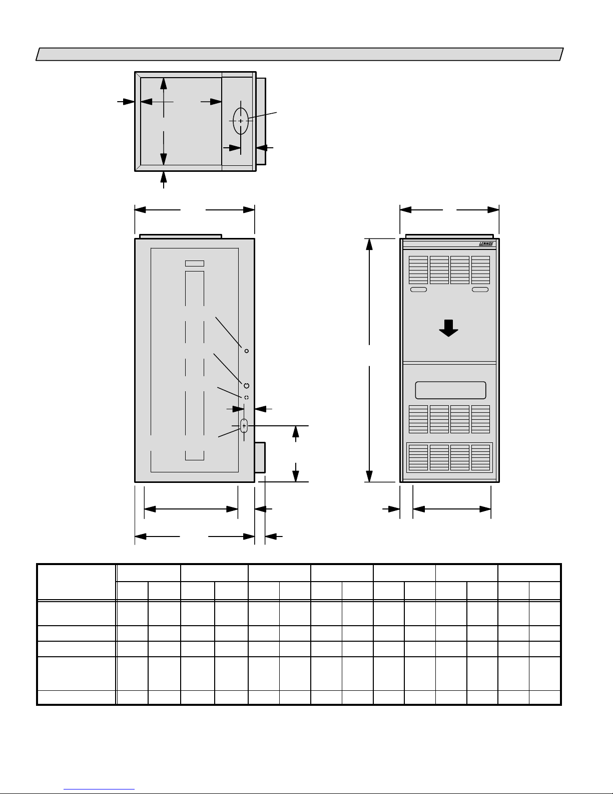
G20R UNIT DIMENSIONS–INCHES (MM)
1Ć1/16
(27)
B
1Ć1/16
17Ć3/4
(451)
RETURN
AIR
OPENING
(27)
26Ć1/8
(664)
FLUE OUTLET
(center side to side)
N O T E Ċ Supply air opening is equipped with a 5/8 in. (16 mm) flange on
E
sides and rear of furnace and may be bent 90 for plenum connecĆ
tion or to help in alignment with cooling coil.
ă*Dimensions before flanges are bent (as shipped).
**Dimensions after flanges are bent.
Dimension after flange (furnished) is field installed on unit.
A
WHISPER HEAT
Model No.
CONTROL VOLTAGE
(Left Side)
LINE VOLTAGE
(Both Sides)
CONTROL VOLTAGE
(Right Side)
GAS PIPING INLET
(Both Sides)
2Ć5/8
(67)
ă8 (203) Right Side
53
(1346)
AIR FLOW
11 (279) Left Side
*19Ć5/8 (498)
**20Ć1/4 (541)
Supply Air
Opening
26Ć1/8
(664)
3Ć3/8
(86)
2Ć3/8
(60)
D
C
Supply Air
Opening
A B *C **C *D **D E
inch mm inch mm inch mm inch mm inch mm inch mm inch mm
G20RQ2/3(X)EĆ50
G20RQ3(X)EĆ75
16Ć1/4 413 14Ć1/8 359 10Ć3/4 273 12 305 1Ć1/2 38 2Ć1/8 54 3Ć1/8 79
G20RQ4(X)EĆ75 21Ć1/4 540 19Ć1/8 486 15Ć3/4 400 17 432 1Ć1/2 38 2Ć1/8 54 3Ć1/8 79
G20RQ3/4(X)EĆ100 21Ć1/4 540 19Ć1/8 486 15Ć3/4 400 17 432 1Ć1/2 38 2Ć1/8 54 3Ć1/4 83
G20RQ5(X)EĆ100
G20RQ3(X(EĆ125
26Ć1/4 667 24Ć1/8 613 18Ć3/4 475 20 508 2Ć1/2 64 3Ć1/8 79 3Ć5/16 84
G20RQ4/5(X)EĆ125
G20RQ4/5EĆ150 31Ć1/4 794 29Ć1/8 740 22 559 24Ć1/4 616 2Ć7/8 73 3Ć1/2 89 3Ć1/2 89
Page 2
Page 3
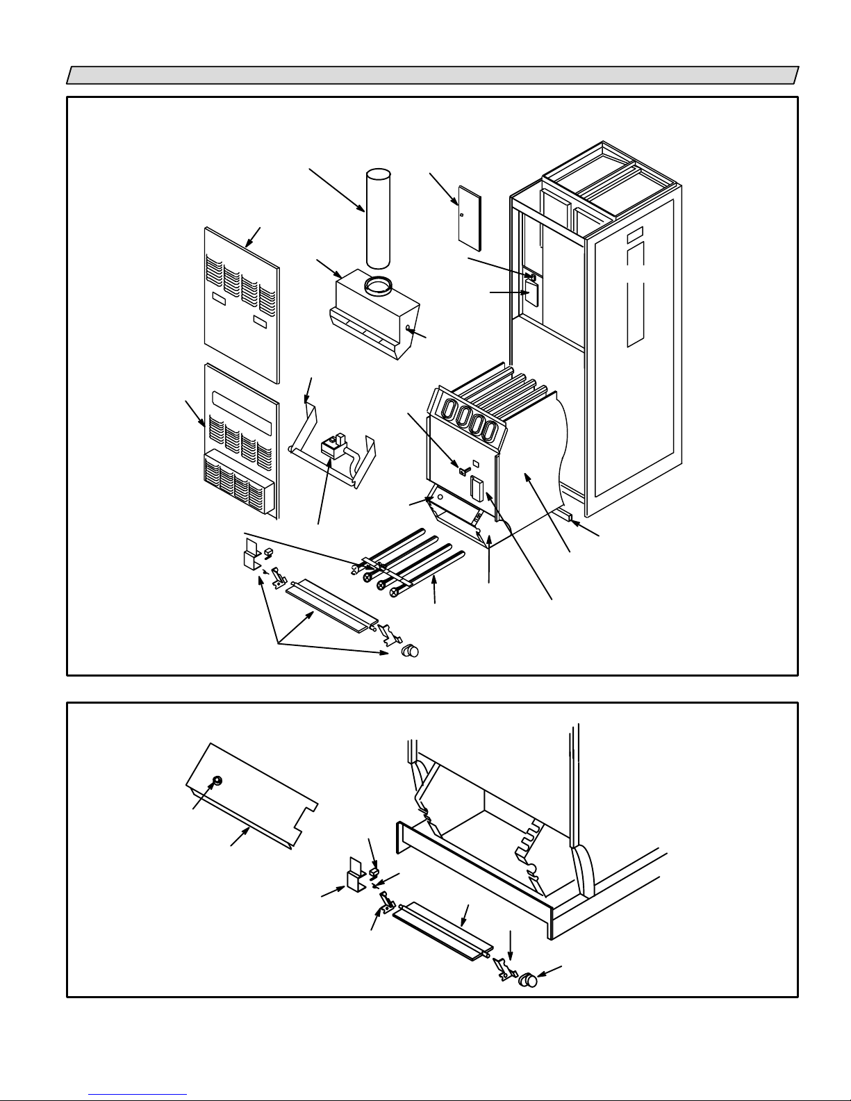
G20R PARTS ARRANGEMENT
PARTS IDENTIFICATION
(G20R Unit Shown)
LOWER
ACCESS
PANEL
PILOT/ELECTRODE
ASSEMBLY
FLUE TRANSITION
UPPER ACCESS
PANEL
DRAFT
HOOD
MANIFOLD
GAS VALVE
GAS
FILTER ACCESS
PRIMARY
LIMIT
CONTROL
ROLL-OUT
SWITCH
DOOR
DOOR
INTERLOCK
SWITCH
BCC
CONTROL
BLOCKED VENT
SHUT-OFF
SWITCH
BURNER BOX
BURNERS
.
.
EXCHANGER
IGNITION
CONTROL
CABINET
REMOVABLE STRIP
HEAT
ROLL-OUT
SWITCH
REMOVABLE
BURNER BOX TOP
BURNER BOX
DAMPER ASSEMBLY
SWITCH COVER
FIGURE 1
DAMPER BOX PARTS ARRANGEMENT
(G20R Units Shown)
DAMPER
SWITCH
SPRING
DAMPER
PATC H
PLATE
BURNER
BOX
DAMPER
PATCH PLATE
FIGURE 2
DAMPER
MOTOR/GEAR
Page 3
Page 4
REQUIREMENTS
In the US, installation of Lennox gas central furnaces
must conform with local building codes or, in the abĆ
sence of local codes, with the current National Fuel Gas
Code (ANSI-Z223.1). The National Fuel Gas Code is
available from:
American National Standards Institute, Inc.
1430 Broadway
New York, NY 10018
All G20R units are A.G.A. (American Gas Association)
and C.G.A (Canadian Gas Association) certified.
NOTE-G20RXE series units (units equipped with flame
rods) are certified for use with natural gas only.
Air supply for combustion and ventilation must conĆ
form to the methods outlined in the current National
Fuel Gas Code.
WARNING
Product contains fiberglass wool.
Disturbing the insulation in this product during
installation, maintenance, or repair will expose you
to fiberglass wool. Breathing this may cause lung
cancer. (Fiberglass wool is known to the State of
California to cause cancer.)
Fiberglass wool may also cause respiratory, skin,
and eye irritation.
To reduce exposure to this substance or for further
information, consult material safety data sheets
available from address shown below, or contact
your supervisor.
Lennox Industries Inc.
P.O. Box 799900
Dallas, TX 75379-9900
The furnace is certified for installation clearances to
combustible material as listed on the appliance rating
plate and in table 1:
TABLE 1
Clearances Location Inches (mm)
Service access
To combustible
materials
From draft hood relief
opening
NOTE-Service access clearance must be maintained.
* If tight installation, front service clearance may be 24" (610mm).
** Clearance is 1" (25mm) for type B1 vent.
Accessibility and service clearances must take preceĆ
dence over fire protection clearances.
Vent installations shall be in accordance with the curĆ
rent GAMA/A.G.A. venting tables manual (502,567M),
or applicable provisions of local building codes. Vent
connectors serving appliances vented by natural draft
shall not be connected into any portion of mechanical
draft systems operating under positive pressure.
Front
Top, side and rear
Flue
Front
36 in. (914mm)*
1 in. (25mm)
6 in. (152mm)**
6 in. (152mm)
NOTE-For installation on combustible floors, appliance
shall not be installed directly on carpeting, tile, or other
combustible material other than wood flooring.
For installation in a residential garage, unit must be
installed so that burner(s) and ignition source are loĆ
cated no less than 18 in. (457 mm) above floor. Furnace
must be located or protected to avoid physical damage
by vehicles.
Unit must be adjusted to obtain a temperature rise
within the range specified on appliance rating plate.
The draft hood shall be installed in the same atmospheric
pressure zone as the combustion air inlet to the furnace.
G20R unit must be installed so that electrical compoĆ
nents are protected from water.
When furnace is used in conjunction with cooling
units, it shall be installed in parallel with, or on the upĆ
stream side of, cooling units to avoid condensation in
the heating element. With a parallel flow arrangement,
damper (or other means to control the flow of air) shall
be adequate to prevent chilled air from entering the
furnace and, if manually operated, must be equipped
with means to prevent operation of either unit, unless
damper is in the full heat" or cool" position.
When installed, furnace must be electrically grounded
in accordance with local codes or, in the absence of loĆ
cal codes, with the current National Electric Code,
ANSI/NFPA No. 70. The National Electric Code (ANSI/
NFPA No. 70) is available from:
National Fire Protection Association
470 Atlantic Avenue
Boston, MA 02210
Field wiring connection with unit must meet or exceed
specifications of type T wire and withstand a 63F
(17C) temperature rise. When furnace is installed so
that supply ducts carry air circulated by furnace to
areas outside space containing furnace, return air shall
be handled by a duct(s) sealed to the furnace casing
and terminating outside space containing furnace.
This furnace is certified for installation clearances to
combustible material as listed on appliance rating plate
and in table 1. Accessibility and service clearances must
take precedence over fire protection clearances.
n Canada, installation of C.G.A. certified units must conĆ
form with current Standard CAN/CGA-B149.1 Installation
Code for Natural Gas Burning Appliances and Equipment"
and CAN/CGA-B149.2 In s t a l l a t i o n C o d e f o r P r o p a n e G a s
Burning Appliances and Equipment," local plumbing or
waste water codes and other applicable local codes. AuĆ
thorities having jurisdiction should be consulted before
installation. Adequate clearance shall be made around air
Page 4
Page 5

openings into the vestibule area. Provisions shall be made
for proper operation and for combustion air and ventilaĆ
tion air supply according to the current CAN/CGA-B149
standards.
All electrical wiring and grounding for the unit must be
in accordance with the current regulations of the CanaĆ
dian Electrical Code Part I (C.S.A. Standard C22.1) and/
or local codes.
NOTE Ċ G20R series units must
not be used as a construction
heater" at any time during any
phase of construction. Very low return air temperaĆ
tures, harmful vapors and misplacement of the filters
will damage the unit and its efficiency.
GENERAL
These instructions are intended as a general guide
and do not supersede local codes in any way. AuthoriĆ
ties having jurisdiction should be consulted before
installation.
A-Shipping and Packing List
1-Rubber grommet (for electrical make-up)
1-Base bottom angle
2-Sheet metal screws
B-Shipping Damage
Check unit for shipping damage. Receiving party
should contact last carrier immediately if any shipping
damage is found.
COMBUSTION, DILUTION & VENTILATION AIR
Until recently, there was no problem in bringing in suffiĆ
cient amounts of outdoor air for combustion -- infiltration
provided all the air that was needed and then some. In
today's homes built with energy conservation in mind,
tight construction practices make it necessary to bring in
air from outside for combustion. Consideration must also
be given to the use of exhaust fans, appliance vents, chimĆ
neys and fireplaces because they force additional air that
could be used for combustion out of the house. Unless
outside air is brought into the home for combustion, negĆ
ative pressure (pressure outside is greater than inside
pressure) will build to the point that a down draft can ocĆ
cur in the furnace vent pipe or chimney. Combustion
gases enter the living space creating a potentially dangerĆ
ous situation.
In the absence of local codes concerning air for combusĆ
tion and ventilation, this section outlines guidelines and
recommends procedures for installing G20R furnaces in
a manner that ensures efficient and safe operation. SpeĆ
cial consideration must be given to combustion air needs
as well as requirements for exhaust vents and gas pipĆ
ing. A portion of this information has been reprinted with
permission from the National Fuel Gas Code (ANSIZ223.1). This reprinted material is not the complete and
official position of the ANSI on the referenced subject,
which is represented only by the standard in its entirety.
In Canada, refer to the standard CAN/CGA-B149.1 and
-B149.2 installation codes.
Combustion Air Requirements
CAUTION
Insufficient combustion air can cause headaches,
nausea, dizziness or asphyxiation. Excessive exĆ
posure to contaminated combustion air will result
in safety and performance related problems. Avoid
exposure to the following substances in the comĆ
bustion air supply:
Permanent wave solutions;
Chlorinated waxes and cleaners;
Chlorine base swimming pool chemicals;
Water softening chemicals;
De-icing salts or chemicals;
Carbon tetrachloride;
Halogen type refrigerants;
Cleaning solvents (such as perchloroethylene);
Printing inks, paint removers, varnishes, etc.;
Hydrochloric acid;
Cements and glues;
Antistatic fabric softeners for clothes dryers; and
Masonry acid washing materials.
All gas-fired appliances require air to be used for the
combustion process. If sufficient amounts of combusĆ
tion air are not available, the furnace or other appliance
will operate in an inefficient and unsafe manner.
Enough air must be provided to meet the needs of all
fuel-burning appliances, as well as appliances such as
exhaust fans which force air out of the home. When fireĆ
places, exhaust fans, or clothes dryers are used at the
same time as the furnace, much more air is required to
ensure proper combustion and to prevent a down-draft
situation. Insufficient amounts of air also cause incomĆ
plete combustion which can result in carbon monoxide.
The requirements for providing air for combustion and
ventilation depend largely on whether the furnace is
installed in an unconfined or confined space.
Unconfined Space
An unconfined space is an area such as a basement or
large equipment room with a volume greater than 50
cubic feet per 1,000 Btu per hour of the combined input
rating of all appliances installed in that space. This
space also includes adjacent rooms which are not sepĆ
arated by a door. Though an area may appear to be unĆ
confined, it might be necessary to bring in outdoor air
for combustion if the structure does not provide
enough air by infiltration. If the furnace is located in a
Page 5
Page 6
building of tight construction with weather stripping
and caulking around the windows and doors, follow
the procedures outlined for using air from the outside
for combustion and ventilation.
Confined Space
A confined space is an area with volume less than 50 cuĆ
bic feet per 1,000 Btu per hour of the combined input ratĆ
ing of all appliances installed in that space. This definiĆ
tion includes furnace closets or small equipment rooms.
When the furnace is installed so that supply ducts carry
air circulated by the furnace to areas outside the space
containing the furnace, the return air must be handled
by ducts which are sealed to the furnace casing and
which terminate outside the space containing the furĆ
nace. This is especially important when the furnace is
mounted on a platform in a confined space such as a
closet or small equipment room. Even a small leak
around the base of the unit at the platform or at the reĆ
turn air duct connection can cause a potentially danĆ
gerous negative pressure condition. Air for combusĆ
tion and ventilation can be brought into the confined
space either from inside the building or from outside.
Air from Inside
If the confined space housing the furnace adjoins space
categorized as unconfined, air can be brought in by proĆ
viding two permanent openings between the two
spaces. Each opening must have a minimum free area of
1 square inch per 1,000 Btu per hour of total input rating
of all gas-fired equipment in the confined space. Each
opening must be at least 100 square inches. One opening
shall be within 12 inches of the top of the enclosure and
one opening within 12 inches of the bottom. See figure 3.
EQUIPMENT IN CONFINED SPACE
CHIMĆ
NEY OR
GAS
VENT
ALL AIR FROM INSIDE
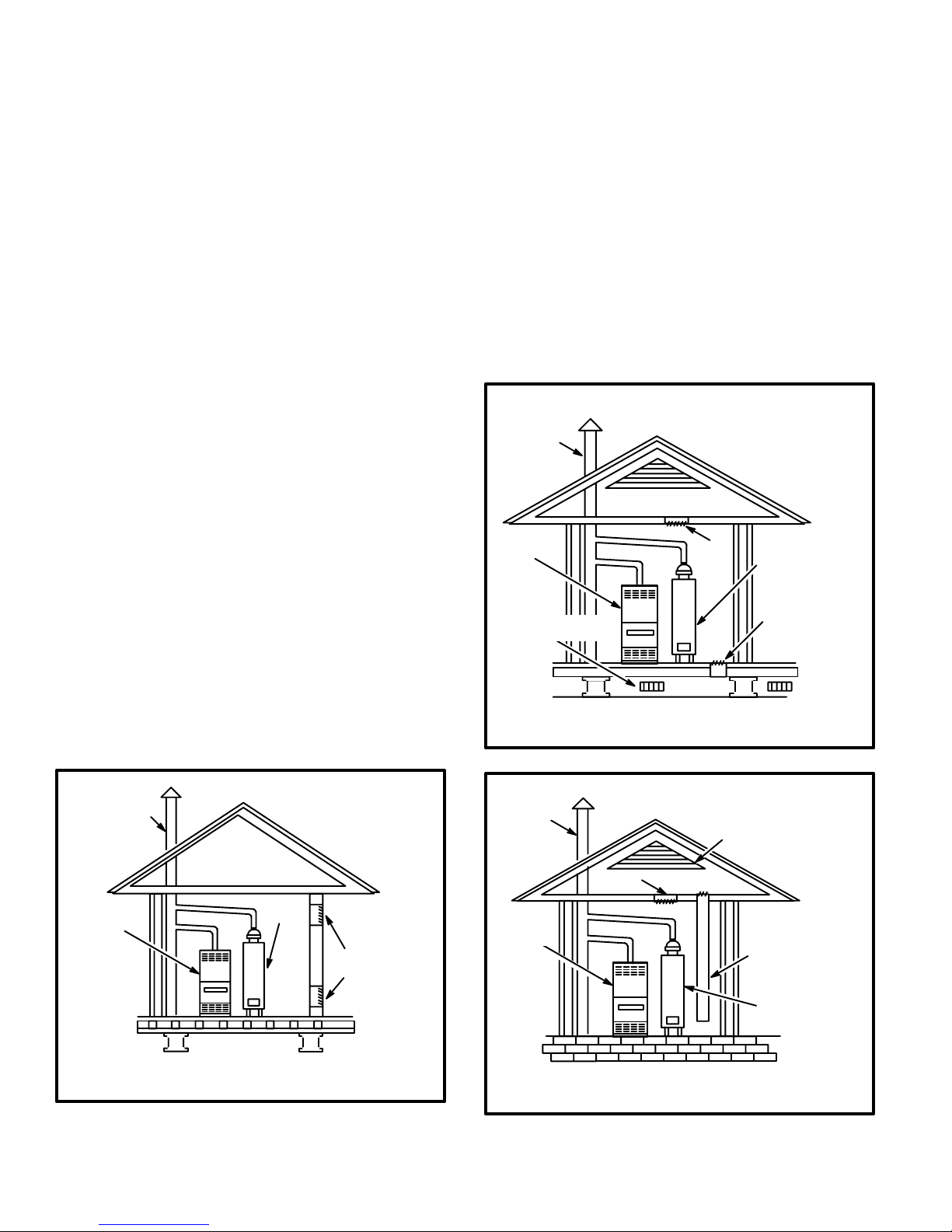
Air from Outside
If air from outside is brought in for combustion and venĆ
tilation, the confined space must have two permanent
openings. One opening shall be within 12 inches of the
top of the enclosure and one within 12 inches of the botĆ
tom. These openings must communicate directly or by
ducts with the outdoors or spaces (crawl or attic) that freeĆ
ly communicate with the outdoors or indirectly through
vertical ducts. Each opening shall have a minimum free
area of 1 square inch per 4,000 Btu per hour of total input
rating of all equipment in the enclosure. See figures 4 and
5. When communicating with the outdoors through horiĆ
zontal ducts, each opening shall have a minimum free
area of 1 square inch per 2,000 Btu per total input rating of
all equipment in the enclosure. See figure 6.
EQUIPMENT IN CONFINED SPACE
ALL AIR FROM OUTSIDE
CHIMNEY
OR GAS
VENT
G20R
FURNACE
VENTILATION
LOUVERS
(For unheated crawl space)
NOTE-The inlet and outlet air openings shall each have a
free area of at least one square inch per 4,000 Btu per hour
of the total input rating of all equipment in the enclosure.
(Inlet Air from Crawl Space and Outlet
VENTILATION LOUVERS
(Each end of attic)
Air to Ventilated Attic)
OUTLET
AIR
WATER
HEATER
INLET
AIR
FIGURE 4
EQUIPMENT IN CONFINED SPACE
CHIMNEY
OR GAS
VENT
ALL AIR FROM OUTSIDE
(All Air Through Ventilated Attic)
VENTILATION LOUVERS
(Each end of attic)
G20R
FURNACE
NOTE-Each opening shall have a free area of at least one
square inch per 1,000 Btu per hour of the total input rating of all
equipment in the enclosure, but not less than 100 square inches.
WATER
HEATER
FIGURE 3
OPENINGS
(To Adjacent
Room)
Page 6
OUTLET
AIR
G20R
FURNACE
NOTE-The inlet and outlet air openings shall each have a free area of
at least one square inch per 4,000 Btu per hour of the total input rating
of all equipment in the enclosure.
INLET AIR
(Ends 12" above
bottom)
WATER
HEATER
FIGURE 5
Page 7
When ducts are used, they shall be of the same crosssectional area as the free area of the openings to which
they connect. The minimum dimension of rectangular
air ducts shall be no less than 3 inches. In calculating
free area, the blocking effect of louvers, grilles, or
screens must be considered. If the design and free area
of protective covering is not known for calculating the
size opening required, it may be assumed that wood
louvers will have 20 to 25 percent free area and metal
louvers and grilles will have 60 to 75 percent free area.
Louvers and grilles must be fixed in the open position
or interlocked with the equipment so that they are
opened automatically during equipment operation.
EQUIPMENT IN CONFINED SPACE
ALL AIR FROM OUTSIDE
CHIMNEY
OR GAS
VENT
WATER
HEATER
OUTLET AIR
G20R
FURNACE
INLET AIR
NOTE-Each air duct opening shall have a free area of at least one
square inch per 2,000 Btu per hour of the total input rating of all equipĆ
ment in the enclosure. If the equipment room is located against an outĆ
side wall and the air openings communicate directly with the outdoors,
each opening shall have a free area of at least one square inch per
4,000 Btu per hour of the total input rating of all other equipment in the
enclosure.
FIGURE 6
INSTALLATION–Setting Equipment
The G20R series units can be installed in three different
ways: on non-combustible flooring, on combustible
floor using an additive base, or on a reverse-flow coolĆ
ing cabinet. Do not drag unit across floor.
A-Installation on Non-Combustible Flooring
1- Cut floor opening keeping in mind the clearances
listed on the unit rating plate. Also, keep in mind gas
supply and electrical supply, vent connections and
sufficient installation and service clearances. See
table 2 for correct floor opening size.
TABLE 2
NONCOMBUSTIBLE FLOOR
UNIT
Q2/3-50, Q3-75
Q4-75, Q3/4-100
Q5-100, Q3-125, Q4/5-125
Q4/5-150
NOTE-Floor opening dimensions listed are 1/4" (6mm) larger
than unit openings.
Front to Rear Side to Side
in mm in mm
20-1/2
20-1/2
20-1/2
20-1/2
520
520
520
520
12-1/4
17-1/4
22-1/4
27-1/4
311
438
565
692
2- Flange warm air plenum and lower into opening.
3- Use duckbill pliers to bend
unit flanges out from openĆ
INSTALLING
BASE ANGLE
ing. Install provided base
bottom angle (shipped in
vestibule panel) to outside of
base into provided holes.
See illustration at right. SeĆ
cure with screws provided.
4- Set unit over plenum.
5- Check to see that an adequate seal is made.
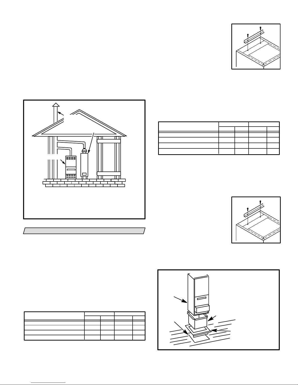
B-Installation on Combustible Flooring
1- When unit is installed on a combustible floor, an addiĆ
tive base (ordered separately) must be installed beĆ
tween the furnace and the floor. See table 3 for openĆ
ing size to cut in the floor.
TABLE 3
ADDITIVE BASE FLOOR OPENING
UNIT
Q2/3-50, Q3-75
Q4-75, Q3/4-100
Q5-100, Q3-125, Q4/5-125
Q4/5-150
NOTE-Floor opening dimensions listed are 1/4" (6mm) larger
than unit openings.
Front to Rear Side to Side
in mm in mm
22-7/8 581
22-7/8
22-7/8
22-7/8
581
581
581
14-5/8
19-5/8
24-5/8
29-5/8
371
498
625
752
2- After opening is cut, set the additive base into opening.
3- Check fiberglass strips on additive base to make sure
they are properly glued and positioned.
4- Lower supply air plenum into additive base until pleĆ
num flanges seal against fiberglass strips.
5- Use duckbill pliers to bend
unit flanges out from openĆ
INSTALLING
BASE ANGLE
ing. Install provided base
bottom angle (shipped in
vestibule panel) to outside of
base into provided holes.
See illustration at right. SeĆ
cure with screws provided.
6- Set unit on additive base so unit flanges drop into pleĆ
num. Refer to figure 7.
NOTE-Be careful not to damage fiberglass strips.
Check for tight seal.
1. Cut correct size floor opening
2. Set additive base into opening.
G20R UNIT
PROPERLY
SIZED
FLOOR
OPENING
3. Set supply air plenum into
additive base.
4. Set unit.
SUPPLY AIR
PLENUM
ADDITIVE
BASE
FIGURE 7
Page 7
Page 8

C-Installation on Cooling Cabinet
1- Refer to reverse-flow coil installation instructions for corĆ
rectly sized opening in floor and installation of cabinet.
2- Use duckbill pliers to bend
unit flanges out from openĆ
INSTALLING
BASE ANGLE
ing. Install provided base
bottom angle (shipped in
vestibule panel) to outside of
base into provided holes.
See illustration at right. SeĆ
cure with screws provided.
3- With cooling cabinet in place, install furnace so
flanges drop inside cabinet opening. Secure furnace
to cabinet.
4- Seal cabinet and check for air leakage.
RETURN AIR OPENING GUIDELINES
Take the following steps when installing return air
plenum:
1- Bottom edge of plenum should be flanged with a
hemmed edge. See figure 8.
2- Fiberglass sealing strips should be used between pleĆ
num and the unit cabinet to ensure a tight seal.
3- In all cases, the plenum should be secured to the top
flanges of the furnace using sheet metal screws. See
figure 8.
PLENUM
FIBERGLASS
SEALING STRIP
CABINET SIDE PANEL
SECURE
HEMMED EDGE
FIGURE 8
WARNING
Do not put sheet metal screws into top of furnace.
Sheet metal screws must be installed into flange of
furnace. Note warning stickers on unit. MisplaceĆ
ment of screws may prevent normal maintenance
of filters.
4- In closet installations, it may be necessary to install
sheet metal screws from the inside. If this is the case,
make plenum with a removable front to install screws
as shown in figure 9.
SECURE FROM
INSIDE
FIBERGLASS
SEALING STRIP
CABINET SIDE PANEL
FIGURE 9
PLENUM
HEMMED EDGE
WARNING
Improper installation of unit can result in personal
injury or death. Combustion and flue products must
never be allowed to enter the return air system or air
in the living space. Use sheet metal screws and joint
tape to seal return air system to furnace.
The furnace should be sealed airtight to the return
air plenum. A door must never be used as a portion
of the return air duct system. Allow absolutely no
sagging, cracks, gaps, etc.
For no reason should return and supply air duct
systems ever be connected to or from other heatĆ
ing devices such as a fireplace or stove, etc. Fire,
explosion, carbon monoxide poisoning, personal
injury and/or property damage could result.
WARNING
Blower door must be securely in place when blowĆ
er and burners are operating. Gas fumes, which
could contain carbon monoxide, can be drawn into
living space resulting in personal injury or death.
DUCT SYSTEM
Size and install the supply and return air duct system usĆ
ing industry-approved standards that result in a quiet
and low-static system with uniform air distribution.
Installation of units not equipped with a cooling coil reĆ
quire a removable access panel in the supply air duct.
The access panel should be large enough to permit inĆ
spection of heat exchanger for leaks after installation.
Lennox recommends using the SENSITTM HT kit for
heat exchanger inspections. The access panel must not
allow leaks in the supply air duct system.
VENTING
G20R furnaces must be vented in compliance with all
local codes, the current GAMA/A.G.A. venting tables
manual (502,567M) in the U.S.A. and the current stanĆ
dards of CAN/CGA-B149.1 and -B149.2 in Canada and
these instructions.
The G20R series units have been classified as Category
I type furnaces when vertically vented in accordance
with the latest edition of ANSI Z21.47 Central Furnace
Standard in the U.S.A. and the current standard of
CAN/CGA-B149.1 and B149.2 of the National Gas and
Propane Installation Code in Canada.
General Venting Recommendations & Requirements
For Using Masonry Chimney
Any masonry chimney used for venting a G20R gas furĆ
nace must be lined, and must be sized and installed per
all applicable local building codes or, in the absence of
local codes, the current National Fuel Gas Code (ANSIZ223.1) in the U.S.A. and the current standards of CAN/
Page 8
Page 9

CGA-B149.1 and -B149.2 in Canada. The effective area
of the chimney serving a single appliance must be no
less than the effective area of the draft hood outlet. The
chimney must extend vertically at least 5 feet above the
flue collar.
The G20R gas furnace must not be connected to a
chimney servicing a separate appliance designed to
burn solid fuel.
Masonry chimneys serving fireplaces cannot be used
for venting purposes unless the fireplace opening is
permanently sealed. See figure 10.
When inspection reveals that an existing chimney is
not safe for the intended purpose, it shall be rebuilt to
conform to nationally recognized standards, lined or
relined with suitable materials or replaced with a gas
vent or chimney suitable for venting G20R series units.
The chimney passageway must be checked periodicalĆ
ly to ensure that it is clear and free of obstructions.
on any exhaust fans, such as range hoods and bathĆ
room exhausts, so they will operate at maximum
speed. Do not operate a summer exhaust fan. Close
fireplace dampers.
4- Follow the lighting instructions. Place the appliance
being inspected in operation. Adjust thermostat so
appliance will operate continuously.
5- Test for spillage at the draft hood relief opening after 5
minutes of main burner operation. Use the flame of a
match or candle, or smoke from a cigarette, cigar or pipe.
6- After it has been determined that each appliance reĆ
maining connected to the common venting system
properly vents when tested as outlined above, return
doors, windows, exhaust fans, fireplace dampers and
any other gas-burning appliance to their previous
condition of use.
7- If improper venting is observed during any of the above
tests, the common venting system must be corrected.
VERTICAL VENT
USING LINED
MASONRY CHIMNEY
H
G20R
FURNACE
L
PERMANENTLY
SEALED FIREĆ
PLACE OPENING
FIGURE 10
Removal of Unit from Common Venting System
In the event that an existing furnace is removed from a
venting system commonly run with separate gas apĆ
pliances, the venting system is likely to be too large to
properly vent the remaining attached appliances. The
following test should be conducted while each apĆ
pliance in operation and the other appliances not in opĆ
eration remain connected to the common venting sysĆ
tem. If the venting system has been installed
improperly, the system must be corrected as outlined
in the previous section.
1- Seal any unused openings in the common venting
system.
2- Visually inspect the venting system for proper size and
horizontal pitch and determine there is no blockage or
restriction, leakage, corrosion and other deficiencies
which could cause an unsafe condition.
3- Insofar as is practical, close all building doors and
windows and all doors between the space in which
the appliances remaining connected to the common
venting system are located and other spaces of the
building. Turn on clothes dryers and any appliances
not connected to the common venting system. Turn
Horizontal Venting
This furnace is design certified by the American Gas
Association for horizontal venting through an outside
wall only with the use of a Field Controls Company
Model #SWG-5L side wall venting kit available from
Lennox Dealer Service Center. No other Field brand
venting kit or any other manufacturer's venting kit is acĆ
ceptable. Horizontal venting of this furnace without the
use of the above stated kit is prohibited. See figure 11
for field wiring of side wall horizontal venting kit.
When horizontally vented, minimum clearance for terĆ
mination from electric meters, gas meters, regulators
and relief equipment is 4 ft. (1.2m).
At vent termination, care must be taken to maintain proĆ
tective coatings over building materials (prolonged exĆ
posure to exhaust condensate can destroy protective
coatings). It is recommended that the exhaust outlet not
be located within 6 ft. (1.8m) of a condensing unit beĆ
cause the condensate can damage the painted coating.
SIDE WALL VENTING KIT WIRING
CK-40 CONTROL BOX
C
PPC-5
(OPTIONAL)
PRESSURE
SWITCH
NO
L1
120VAC
L2
3
1
L1 MN
75
A
B
RELAY
T1 T2 T3
M
THERMOSTAT CONNECTIONS
TERMINAL IN FURNACE
JUNCTION BOX
WR Y G
SWG
POWER
VENTER
MOTOR
FACTORY INSTALLED WIRING
FIELD INSTALLED WIRING
T
G
R
W
Y
24 VAC
THERMOSTAT
FIGURE 11
Page 9
Page 10

GAS PIPING
Nominal
Internal
Gas Supply
1- This unit is shipped standard for left side installation of
gas piping. Simply connect gas supply to piping asĆ
sembly.
2- A piping hole is also fabricated in the right side of the
unit for alternate piping arrangements.
3- When connecting gas supply, factors such as length
of run, number of fittings and furnace rating must be
considered to avoid excessive pressure drop. Table 4
lists recommended pipe sizes for typical applications.
4- Gas piping must not run in or through air ducts,
clothes chutes, chimneys or gas vents, dumb waiters
or elevator shafts.
5- Piping should be sloped 1/4 inch per 15 feet upward toĆ
ward the meter from the furnace. The piping must be
supported at proper intervals (every 8 to 10 feet) using
suitable hangers or straps. A drip leg should be installed
in vertical pipe runs to the unit.
6- In some localities, codes may require installation of a
manual main shut-off valve and union (furnished by
installer) external to the unit. Union must be of the
ground joint type.
unit. Tap must be accessible for test gauge connection.
See figure 12.
NOTE-In case emergency shutoff is required, shut off
main manual gas valve and disconnect main power to
unit. These devices should be properly labeled by the inĆ
staller.
MANUAL
MAIN SHUT-OFF VALVE
(With 1/8" NPT
Plugged Tap Shown)
GROUND
JOINT
UNION
FIELD
PROVIDED
AND INSTALLED
(with manual shut-off valve)
DRIP LEG
AUTOMATIC
GAS VALVE
LEFT SIDE PIPING
(STANDARD)
AUTOMATIC GAS VALVE
(with manual shut-off valve)
RIGHT SIDE PIPING
(ALTERNATE)
MANUAL
MAIN SHUT-OFF VALVE
(With 1/8" NPT
Plugged Tap
Shown)
IMPORTANT
Compounds used on threaded joints of gas piping
must be resistant to the actions of liquified pertoĆ
leum gases.
NOTE-Installer must provide a
1/8" N.P.T. plugged tap in the
field piping upstream of the gas supply connection to the
24
(.68)
52
(1.47)
97
(2.75)
200
(5.66)
375
(10.62)
770
(21.80)
1180
(33.41)
2200
(62.30)
3520
(99.67)
TABLE 4
Nominal Internal
Iron Pipe Size
-Inches(mm)
1/4
(6.35)
3/8
(9.53)
1/2
(12.7)
3/4
(19.05)
1
(25.4)
1-1/4
(31.75)
1-1/2
(38.1)
2
(50.8)
2-1/2
(63.5)
Diameter
-Inches(mm)
.364
(9.246)
.493
(12.522)
.622
(17.799)
.824
(20.930)
1.049
(26.645)
1.380
(35.052)
1.610
(40.894)
2.067
(52.502)
2.469
(67.713)
GAS PIPE CAPACITY - FT3/HR (kL/HR)
10
(3.048)20(6.096)30(9.144)40(12.192)50(15.240)60(18.288)70(21.336)80(24.384)90(27.432)
43
(1.13)
95
(2.69)
175
(4.96)
360
(10.19)
680
(19.25)
1400
(39.64)
2100
(59.46)
3950
(111.85)
6300
(178.39)
29
(.82)
65
(1.84)
120
(3.40)
250
(7.08)
465
(13.17)
950
(26.90)
460
(41.34)
2750
(77.87)
4350
(123.17)
Length of Pipe-Feet(m)
20
(.57)
45
(1.27)
82
(2.32)
170
(4.81)
320
(9.06)
660
(18.69)
990
(28.03)
1900
(53.80)
3000
(84.95
18
(.51)
40
(1.13)
73
(2.07)
151
(4.28)
285
(8.07)
580
(16.42)
900
(25.48)
1680
(47.57)
2650
(75.04)
16
(.45)
36
(1.02)
66
(1.87)
138
(3.91)
260
(7.36)
530
(15.01)
810
(22.94)
1520
(43.04)
2400
(67.96)
FIGURE 12
15
(.42)
33
(.73)
61
(1.73)
125
(3.54)
240
(6.80)
490
(13.87)
750
(21.24)
1400
(39.64)
2250
(63.71)
(13.03)
(19.54)
(36.81)
(58.05)
14
(.40)
31
(.88)
57
(1.61)
118
(3.34)
220
(6.23)
460
690
1300
2050
GROUND
JOINT
UNION
DRIP LEG
13
(.37)
29
(.82)
53
(1.50)
110
(3.11)
205
(5.80)
430
(12.18)
650
(18.41)
1220
(34.55)
1950
(55.22)
100
(30.480)
12
(.34)
27
(.76)
50
(1.42)
103
(2.92)
195
(5.52)
400
(11.33)
620
(17.56)
1150
(32.56)
1850
(52.38)
Page 10
Page 11

3
(76.2)
4
(101.6)
3.068
(77.927)
4.026
(102.260)
11000
(311.48)
23000
(651.27)
7700
(218.03)
15800
(447.39)
6250
(176.98)
12800
(362.44)
5300
(150.07)
10900
(308.64)
4750
(134.50)
9700
(274.67)
4300
(121.76)
8800
(249.18)
3900
(110.43)
8100
(229.36)
3700
(104.77)
7500
(212.37)
NOTE-Capacity given in cubic feet of gas per hour (kilo liters of gas per hour) and based on 0.60 specific gravity gas.
3450
(97.69)
7200
(203.88)
3250
(92.03)
6700
(189.72)
Page 11
Page 12

Leak Check
After gas piping is completed, carefully check all piping
connections (factory and field) for gas leaks. Use a leak
detecting solution or other preferred means.
CAUTION
Some soaps used for leak detection are corrosive
to certain metals. Carefully rinse piping thoroughly
after leak test has been completed. Do not use
matches, candles, flame or other sources of igniĆ
tion to check for gas leaks.
NOTE-In case emergency shutdown is required, shut
down main manual gas valve and disconnect main
power to unit. These devices should be properly laĆ
beled by the installer.
IMPORTANT
When testing pressure of gas lines, gas valve must
be disconnected and isolated. See figure 13. Gas
valves can be damaged if subjected to more than
1/2 psig (3.48 kPa).
MANUAL MAIN
SHUT-OFF VALVE
WILL NOT HOLD
NORMAL TEST
PRESSURE
CAP
FIGURE 13
The furnace must be isolated from the gas supply sysĆ
tem by closing its individual manual shut-off valve durĆ
ing any pressure testing of the gas supply system at
pressures equal to or less than 1/2 psig (3.48 kPa).
G20RXE Series Units
IMPORTANT-G20RXE series units (units equipped with
flame rods) are approved for use with natural gas only.
ISOLATE
GAS VALVE
FURNACE
ELECTRICAL
Refer to figure 14 for thermostat wiring, figure 15 for
BCC location, figure 16 for pointĆtoĆpoint field wiring,
and figure 17 for schematic wiring diagram and troubleĆ
shooting.
1- Select fuse and wire size according to motor amps.
2- Snaphole plugs are provided on both sides of cabinet
to facilitate wiring.
3- Install room thermostat according to instructions proĆ
vided with thermostat.
4- Install a separate fused disconnect switch near the
unit so power can be turned off for servicing.
5- Route thermostat wire as shown in figure 14. Keep
wire away from draft hood and flue pipe. Do not route
wire across draft hood.
6- Complete wiring connections to equipment using wiring
diagrams provided with unit and in figures 15, 16 and 17.
Use 18 gauge wire or larger for thermostat connections.
7- Electrically ground unit in accordance with local codes
or, in the absence of local codes, in accordance with the
current National Electric Code (ANSI/NFPA No. 70) and
in Canada with the current Canadian Electric Code part
1 (CSA standard C22.1).
8- A 120 volt accessory terminal (ACC) is provided on
the BCC blower control center. Any accessory rated
up to 1 amp can be connected to this terminal and the
neutral leg of the accessory can be attached to any
free 120 volt neutral terminal on the BCC blower conĆ
trol center. The accessory terminal is energized whenĆ
ever the blower is in operation. See figure 15 . A trouĆ
bleshooting flowchart for the BCC blower control is
located at the end of this manual.
9- The continuous fan (CF) 120 volt terminal is used with
an optional continuous low fan kit that is available
from Lennox. The kit allows the furnace blower to run
continuously on low speed.
10- Check the thermostat selector jumper on the BCC
board. The jumper is factoryĆpositioned for use
with a mechanical thermostat. This jumper must
be repositioned if an electronic thermostat will be
used in the application.
Page 12
Page 13

THERMOSTAT WIRE ROUTING
ROUTE WIRE AWAY FROM
DRAFT HOOD
BCC
G20R BLOWER CONTROL CENTER
ACCESSORY
TERMINAL
HEATING
SPEED TAP
TERMINAL
BLOWER TIME
ADJUSTMENT
JUMPER
GAS VALVE
Left side thermostat wire entry.
Right side thermostat wire entry.
FIGURE 14
IGNITION
CONTROL
DUMMY
TERMINALS
CONTINUOUS
FAN
TERMINAL
COOLING
SPEED TAP
TERMINAL
NEUTRAL
TERMINALS
THERMOSTAT JUMPER
(Electronic or Mechanical)
TYPICAL G20R FIELD WIRING DIAGRAM
DAMPER
DOOR
SWITCH
FLAME
ROLLOUT
SWITCH
BLOCKED
VENT
SHUTOFF
SWITCH
PRIMARY
LIMIT
IGNITION
CONTROL
FIGURE 15
FUSED DISCONNECT SWITCH
(FURNISHED BY INSTALLER)
THERMOSTAT
CONNECTIONS
L1 N
THERMOSTAT
YRWG
TO COMPRESSOR
CONTACTOR
GAS
VALVE
BCC CONTROL
FIGURE 16
SECONDARY
LIMIT
TRANSFORMER
MAKE-UP
BOX
BLACK
WHITE
GWYTR
DOOR
INTERLOCK
SWITCH
FIELD INSTALLED LOW VOLTAGE
FIELD INSTALLED LINE VOLTAGE
GROUND
Page 13
Page 14

TYPICAL G20R WIRING DIAGRAM
FIGURE 17
Page 14
Page 15

UNIT START–UP
FOR YOUR SAFETY READ BEFORE LIGHTING
WARNING
Do not use this furnace if any part has been underĆ
water. Immediately call a qualified service techniĆ
cian to inspect the furnace and to replace any part
of the control system and any gas control which
has been under water.
WARNING
If overheating occurs or if gas supply fails to shut
off, shut off the manual gas valve to the appliance
before shutting off electrical supply.
CAUTION
Before attempting to perform any service or mainĆ
tenance, turn the electrical power to unit OFF at
disconnect switch.
BEFORE LIGHTING smell all around the appliance area
for gas. Be sure to smell next to the floor because some
gas is heavier than air and will settle on the floor.
Use only your hand to push in or turn the gas control
knob. Never use tools. If the knob will not push in or turn
by hand, do not try to repair it, call a qualified service techĆ
nician. Force or attempted repair may result in a fire or exĆ
plosion.
To place G20R furnace into operation:
G20R units are equipped with an intermittent pilot igniĆ
tion system. Do not attempt to manually light pilots on
these furnaces. Each time thermostat calls for heat, the
pilot will automatically light. The pilot goes out when
there is no demand for heat.
WARNING
THERMOSTATS
FIGURE 18
4- This appliance is equipped with an ignition device
which automatically lights the pilot. Do not try to light
the pilot by hand.
5- Remove lower access panel.
6- On Honeywell VR8204 gas valves, turn knob on gas
valve clockwise to OFF. Units with Robertshaw
7200 gas valve, depress lever and move to OFF posiĆ
tion. Do not force. See figures 19 and 20.
7- Wait fifteen (15) minutes to clear out any gas. If you then
smell gas, STOP! Immediately call your gas supplier from
a neighbor's phone. Follow the gas supplier's instrucĆ
tions. If you do not smell gas go to next step.
HONEYWELL VR8204 SERIES GAS VALVE
ON
OFF
GAS VALVE SHOWN IN OFF POSITION
FIGURE 19
ROBERTSHAW 7200 GAS VALVE
GAS VALVE
SELECTOR
ARM
IN OFF
POSITION
If you do not follow these instructions exactly, a fire
or explosion may result causing property damage,
personal injury or loss of life.
Gas Valve Operation (Figures 19 & 20)
1- STOP! Read the safety information at the beginning of
this section.
2- Set thermostat to lowest setting. See figure 18.
3- Turn off all electrical power to appliance.
FIGURE 20
8- On Honeywell VR8204 gas valves, turn knob on gas
valve counterclockwise to ON. Units with RobertĆ
shaw 7200 gas valve, depress lever and move to ON
position. Do not force.
9- Replace lower access panel.
10-Turn on all electrical power to unit.
Page 15
Page 16

11-Set thermostat to desired setting.
NOTE-When unit is initially started, steps 1 through 11
may need to be repeated to purge air from pilot line.
12- If the appliance still will not operate, follow the instrucĆ
tions To Turn Off Gas To Unit" and call your service
technician or gas supplier.
To Turn Off Gas To Unit
1- Set thermostat to lowest setting.
2- Turn off all electrical power to unit if service is to be perĆ
formed.
3- Remove lower access panel.
4- On Honeywell VR8204 gas valves, turn knob on gas
valve clockwise to OFF. Units with Robertshaw 7200
gas valve, depress lever and move to OFF position. Do
not force.
5- Replace lower access panel.
Correct manifold pressure for natural gas is 3.5"
w.c. (.87kPa). No adjustment is needed in high altiĆ
tude applications. See figures 22 and 21 for gas
pressure adjustment screw location.
HONEYWELL GAS VALVE
REGULATOR ADJUSTMENT SCREW LOCATION
PRESSURE REGULATOR
ADJUSTING SCREW
(White)
CAP SCREW
(Black)
INLET
PRESSURE
TAP
GAS INLET
HIGH ALTITUDE INFORMATION
G20R series units are certified for installations from 0 to
4000 feet (0 to 1219m) above sea level without modificaĆ
tion. For installations from 4000 feet to 7500 feet (1219m
to 2286m) above sea level, a high altitude kit (44H56)
must be installed. The kit contains special flue baffles
used to replace factory-installed baffles. No derate is reĆ
quired.
GAS PRESSURE ADJUSTMENT
Gas Flow
To check for proper gas flow to combustion chamber, deĆ
termine Btu input from appliance rating plate. Divide this
input rating by the Btu per cubic foot of available gas. ReĆ
sult is the required number of cubic ft. per hour. DeterĆ
mine the flow of gas through gas meter for two minutes
and multiply by 30 to get the hourly flow of gas to burner.
Gas Pressure
1- Check gas line pressure with unit firing at maximum
rate. A minimum of 4.5" w.c. (1.12kPa) for natural
gas or 10.5" w.c. (2.61kPa) for LP/propane gas
should be maintained.
2- After line pressure has been checked and adjusted,
check manifold pressure. Correct manifold presĆ
sure for LP/propane gas is 9.5" w.c. (2.36kPa) No adĆ
justment is needed in high altitude applications.
A natural gas to LP/propane gas changeover kit is
required to convert unit. Refer to the installation
instructions supplied with changeover kit for conĆ
version procedure.
FIGURE 21
ROBERTSHAW 7200 GAS VALVE
REGULATOR ADJUSTMENT SCREW LOCATION
REGULATOR
COVER SCREW
INLET
PRESSURE
TAP
ADJUSTING
SCREW
FIGURE 22
OTHER UNIT ADJUSTMENTS
Limit Control
Limit Control-Factory set at 90 seconds: No adjustment
necessary. If nuisance tripping of limit control occurs, fan
may need to run longer. See Fan Control section below.
Fan Control
The fan on time of 45 seconds is not adjustable. Fan off
time (time that the blower operates after the heat deĆ
mand has been satisfied) can be adjusted by moving
the jumper on the BCC blower control center. The unit
is shipped with a factory fan off setting of 90 seconds.
Fan off time will affect comfort and is adjustable to satĆ
isfy individual applications. See figure 23.
Page 16
Page 17

FAN OFF TIME ADJUSTMENT
270
150 210
90
90 SECOND FAN
OFF TIME
270
150 210
90
210 SECOND FAN
OFF TIME
NO JUMPER
JUMPER
JUMPER
150 210
JUMPER
270 SECOND FAN
270
330 SECOND FAN
90
270
150
150 SECOND FAN
OFF TIME
270
150 210
90
OFF TIME
OFF TIME
210
90
JUMPER
FIGURE 23
Temperature Rise
Check temperature rise and, if necessary, adjust blowĆ
er speed to maintain temperature rise within range
shown on unit rating plate.
Thermostat Selector Jumper
Check the thermostat selector jumper on the BCC
board. The jumper is factoryĆpositioned for use with a
mechanical thermostat. This jumper must be reposiĆ
tioned if an electronic thermostat will be used in the apĆ
plication.
Thermostat Adjustment
Thermostat anticipator setting (if adjustable) should be
set according to amps listed on wiring diagram on unit.
Electrical
1- Check all wiring for loose connections.
2- Check for correct voltage at unit (unit operating).
3- Check amp-draw on blower motor.
Motor Nameplate__________Actual__________
Flue and Chimney
1- Check flue pipe, chimney and all connections for
tightness and to make sure there is no blockage.
2- Check unit for proper draft.
Blower Speeds
Blower speed tap selection is accomplished by changing
the taps at the harness connector at the blower motor.
Disconnect harness connector from motor to expose
speed selectors. See figure 24 and unit wiring diagram.
1- Turn off electrical power to furnace.
2- Remove filter access panel.
3- Lift left side filter over left support angle. For easy hanĆ
dling, hold filter at center bottom.
4- Rotate filter sideways and pull it through the blower
access panel opening.
5- Grasp blower motor harness connector located on
back on motor. Depress lock tab and pull connector
from motor.
6- Pull harness connector and wires through blower acĆ
cess panel opening.
7- Select desired taps for heating and cooling. (White =
common, Red = heating, Black = cooling)
8- Depress harness connector tab to release wire termiĆ
nal. Select connector location for new speed (refer to
unit wiring diagram). Insert wire terminal until it is seĆ
curely in place. See figure 24.
9- Replace harness connector to motor until it is securely
in place.
BLOWER SPEED TAP SELECTION
HARNESS
CONNECTOR
DEPRESS TAB TO RELEASE
WIRE TERMINAL. SELECT CONĆ
NECTOR LOCATION FOR NEW
SPEED (REFER TO UNIT WIRING
DIAGRAM). INSERT WIRE UNTIL
IT IS SECURELY IN PLACE.
FIGURE 24
Failure to Operate
If unit fails to operate check the following:
1- Is thermostat calling for heat?
2- Is main disconnect switch closed?
3- Is there a blown fuse?
4- Is filter dirty or plugged? Dirty or plugged filters will
cause unit to go off on limit control.
5- Is gas turned on at meter?
6- Is manual main shut-off valve open?
7- Is internal manual shut-off valve open?
After items 1 through 7 have been checked and unit still
will not start, manually reset vent safety shut-off switch
located at the right side of draft hood. If unit operation reĆ
sumes and then cuts out again, inspect furnace vent sysĆ
tem for proper sizing and installation. Also, check for
vent blockage and for proper draft. If unit still does not
start, reset roll-out switch on burner box. See figure 27. If
unit starts and cuts out, check heat section for blockage.
Pilot and Burner Flame
CAUTION
Check pilot flame and burner flame periodically to
ensure proper operation.
1- Pilot Flame -- Pilot flame must surround the end of
flame sensor for proper operation of pilot safety cirĆ
cuit. See figure 25.
Page 17
Page 18

2- Burner Flame -- Start burner and allow to operate for
a few minutes to establish normal burning conditions.
Check burner flame by observation. Flame should be
predominantly blue in color, strong in appearance
and should rise directly from the burner ports in the
heat exchanger. Check to see that flame is burning
from all continuous ribbon ports and that flame does
not impinge on the sides of the heat exchanger. Refer
to figure 26.
FLAME SHOULD
ENGULF UPPER
1/3 OF FLAME SENSOR
BURNER
PILOT FLAME
(Side View)
FLAME SENSOR
TABLE 5
MODEL NO. FILTER SIZE
Q2/3-50, Q3-75
Q4-75, Q3/4-100
Q5-100, Q3-125, Q4/5-125
Q4/5-150 20 X 16 X 1
-150 UNITS
MAKE SURE FILTER IS PLACED
INTO THIS CHANNEL
ROTATE FILTER
TO REMOVE
20 X 10 X 1
20 X 12 X 1
20 X 14 X 1
-150 UNITS
RIGHT
FILTER
LEFT FILTER
TAB
PILOT GAS
LINE
ELECTRODE
FIGURE 25
BURNER FLAME
NOTE-VIEW BURNER FLAME THROUGH
DAMPER OPENING (Not Shown)
FIGURE 26
SERVICE
WARNING
Disconnect power before servicing unit.
CAUTION
Label all wires prior to disconnection when servicĆ
ing controls. Wiring errors can cause improper
and dangerous operation. Verify proper operation
after servicing.
At the beginning of each heating season, the system
should be checked as follows:
Blower
Check and clean blower wheel for any debris. Blower
motor is prelubricated for extended bearing life. No
further lubrication is needed.
Filters
G20R series units are equipped with two permanent inĆ
ternal filters which should be inspected monthly and
cleaned when necessary to assure proper furnace opĆ
eration. See table 5 for filter sizes. Use the following
procedure and figure 27 to clean filter.
RIGHT FILTER
LEFT
SUPPORT
ANGLE
SUPPORT ANGLE
(ON THREE SIDES)
BLOWER
FIGURE 27
1- Turn off electric power to furnace.
2- Remove upper access panel.
3- Remove blower access panel.
4- Lift left side filter over left support angle. For easy hanĆ
dling, hold filter at center bottom.
5- Rotate filter sideways and pull it through the blower
access panel opening.
6- Pull the second filter out the same way as the first.
7- Wash filters with warm water and mild detergent.
When dry, filters should be sprayed with filter handiĆ
coater before replacing. Filter Handicoater is RP prodĆ
ucts coating no. 418 and is available as Lennox part
no. P-8-5069.
8- Right filter should be under tab of right filter support angle.
9-Left filter must rest against top edge of right filter.
Flue and Chimney
Check flue pipe, chimney and all connections for tightĆ
ness and to make sure there is no blockage.
Cleaning Heat Exchanger and Burners
NOTE-Use papers or protective covering in front of furĆ
nace while cleaning furnace.
To clean heat exchanger:
1- Turn off both electrical and gas power supplies to furĆ
nace. Refer to figures 1 and 2 during disassembly and
reassembly procedures.
2- Remove burner and upper access panel, flue pipe
and draft hood.
Page 18
Page 19

3- Disconnect supply gas piping.
4- Remove screws holding burner box damper in place
and remove burner box damper assembly and dampĆ
er prove switch cover.
5- Remove screws securing removable burner box top.
6- Remove screws holding gas manifold in place and
pull burners from heat exchanger.
7- Remove baffles inside top opening of heat exchanger by
twisting tabs too align with slots in baffles.
8- Insert a 2 ft. (600 mm) steel rod that has a 20 in. (508
mm) length of chain attached to one end into top
opening of heat exchanger. See figure 28.
CLEANING HEAT EXCHANGER
Connect chain to rod and drop chain
down through top of heat exchanger.
Connect at bottom to another rod.
Move rods up and down, back and
forth to clean heat exchanger.
CLEANING PORTS
FIGURE 30
CLEANING INSIDE
FIGURE 31
FIGURE 28
9- Shake rod to drop chain through the clamshell into
burner cavity in bottom of heat exchanger.
10- Attach bottom of chain to another 2 ft. (600 mm) rod.
11-Push and pull the rods back and forth and up and
down with a vigorous motion. The chain will dislodge
the soot and scale deposits inside the heat exchangĆ
er. Repeat for each clamshell.
12- With a shop vacuum or rags, clean out soot and scale
deposits from bottom of heat exchanger.
To clean burners:
NOTE-FOR UNITS WITH FLAME RODS, remove two
springs and withdraw rods from back of burner. Clean
flame rods with wire brush. Continue with items 13
through 15 below and reinstall flame rods and springs.
13-Clean top of burner ports with a wire brush. See figĆ
ure 29.
14- Clean burner ports by inserting a cleaning tool (made
from a piece of sheet metal cut to fit the burner ports) and
work in and out of each port. See figure 30.
15-Clean inside of each burner with a bottle cleaning
brush. See figure 31.
CLEANING TOP
16-Replace burners making sure to fully engage in rear
receiving slot in heat exchanger. Resecure gas manĆ
ifold and supply piping.
17-Reinstall baffles inside top opening of heat exchanger
twisting tabs to secure baffles.
18-Resecure damper assembly, damper prove switch
cover and burner box top. Carefully open damper by
hand to ensure that the damper spring closes damper
correctly and that the damper prove switch is enĆ
gaged when damper is open.
CAUTION
Use extreme care when opening damper door to
prevent permanent damage to the damper motor.
19- Before replacing draft hood, flue pipe and access panels,
inspect draft hood gasket. Replace gasket if necessary.
20-Carefully check all piping connections (factory and
field) for gas leaks. Use a leak detecting solution or
other preferred means.
CAUTION
Some soaps used for leak detection are corrosive
to certain metals. Carefully rinse piping thoroughly
after leak test has been completed. Do not use
matches, candles, flame or other sources of igniĆ
tion to check for gas leaks.
FIGURE 29
21-Turn on gas and electrical supply.
Page 19
Page 20

REPAIR PARTS LIST
The following repair parts are available through indeĆ
pendent Lennox dealers. When ordering parts, include
the complete furnace model number listed on the
A.G.A. or C.G.A. rating plate Ċ Example: G20RQ4/5-150.
CABINET PARTS
Upper access panel
Lower access panel
Top strip
Control box cover
ELECTRICAL PARTS
Transformer
Blower Control Center (BCC)
Door Interlock Switch
BLOWER PARTS
Blower wheel
Motor
Motor mounting frame
Blower housing cut-off plate
Motor capacitor
HEATING PARTS
Heat exchanger
Draft hood
Main burners
Main burner orifices
Pilot burner
Gas manifold
Gas valve
Flame sensor
Ignition control
Ignition cable
Igniter
Vent pipe extension Pilot Mounting bracket
Pilot orifice
Main burner with pilot mount
Flue baffles
Pilot/electrode assembly
Primary limit control
Flame roll-out switch
Blocked vent shut-off switch
Damper motor
Damper switch
Couplings
Damper spring
Grommets
G20RE START–UP AND PERFORMANCE CHECK LIST
START-UP AND PERFORMANCE CHECK LIST
Job Name
Job Location
Installer
Unit Model No.
HEATING SECTION
Electrical Connections Tight?
Supply Voltage
Blower Motor H.P.
Blower Motor Lubrication O.K.?
Gas Piping Connections Tight & Leak-Tested?
Fuel Type: Natural Gas? LP/Propane Gas?
Furnace Btu Input
Line Pressure
Regulator Pressure
Blower Motor Amps
w.c. Ċ Nat.: w.c. Ċ LP/Propane
Job No.
City
City
Serial No.
Air Shutters Properly Adjusted (If Installed)?
Fan Control Setting (45 Seconds Fixed On)
Filter Clean & Secure?
Calibrated? Heat Anticipator Properly Set? Level?
Flue Connections Tight?
Date
State
State
Service
Technician
Proper Draft?
Temperature RiseFan Control Off Setting
Vent Clear?
THERMOSTAT
Page 20
Page 21

START
BCC
TROUBLESHOOTING
FLOWCHART
REPLACE
BCC
NO
(REMOVE R & G JUMPER)
NO
IS
120VAC ACROSS
N & ACC?
YES
JUMPER ACROSS
R &W
IS
DAMPER MOTOR
ON?
YES
YES
YES
DOES UNIT
OPERATE?
NO
CHECK FUSE.
REPLACE IF NEEDED.
IS
24VAC ACROSS
R & C?
YES
JUMPER ACROSS
SCREWS R & G
IS
BLOWER
RUNNING ON HIGH
SPEED?
IS
UNIT LIT?
YES
NO
NO
CHECK:
1-UNIT POWER
2-INTERLOCK SWITCH
3-TRANSFORMER
4-LIMIT SWITCH
NO
IS
120VAC ACROSS
N & A?
YES
CHECK BLOWER
WIRING AND
BLOWER
CHECK:
1-DAMPER MOTOR
2-IGNITION CONTROL
3-GAS VALVE
4-IGNITOR
5-LIMIT SWITCHES
6-PROVE SWITCH
NO
REPLACE
BCC
NO
REPLACE
BCC
END OF TEST
IS
120VAC ACROSS
N & CAB?
NO
REPLACE
BCC
YES
YES
IS
120VAC ACROSS
N & ACC?
YES
REMOVE
R & W
JUMPER
AFTER
THE SELECTED
TIME, DOES THE
BLOWER TURN
OFF?
CHECK
DAMPER MOTOR
WIRING AND
DAMPER MOTOR
YES
NO
IS BLOWER
RUNNING ON LOW
SPEED, 45 SEC.
AFTER FURNACE LIGHTS?
REPLACE
BCC
FIGURE 32
NO
IS
120VAC ACROSS
N & H?
NO
IS
24VAC ACROSS
C & V?
NO
CHECK
WIRING
YES
CHECK BLOWER
WIRING AND
BLOWER
YES
REPLACE
BCC
Page 21
 Loading...