

Page 1
INSTALLATION INSTRUCTIONS
G1D91BU, G1D93BC, G1D93BU, CG90CB, & CG90UB
High Efficiency 90+ Condensing Gas Furnace
WARNING
Improper installation, adjustment, alteration, service, or maintenance can cause
injury or property damage. Refer to this manual. For assistance or additional information, consult a qualified installer, service agency, or the gas supplier.
WARNING
Do not store combustible materials, including
gasoline and other flammable vapors and
liquids, near the furnace, vent pipe, or warm
air ducts. The homeowner should be cautioned that the furnace area must not be
used as a broom closet or for any other
storage purposes. Such uses may result in
actions that could cause property damage,
personal injury, or death.
SAFETY ................................................. 2
INSTALLATION....................................... 3
START-UP ............................................ 19
OPERATION ........................................ 20
MAINTENANCE ................................... 23
TABLE OF CONTENTS
REPAIR PARTS .................................... 24
WARNING
This furnace is not approved for installation in
a mobile home. Do not install this furnace in a
mobile home. Installation in a mobile home
could result in actions that could cause property damage, personal injury, or death.
®
The installation of the furnace, wiring, warm air ducts, venting, etc. must conform to the requirements of the
National Fire Protection Association; the National Fuel Gas Code, ANSI Z223.1/NFPA No. 54 (latest edition)
and the National Electrical Code, ANSI/NFPA No. 70 (latest edition) in the United States; CSA B149.1
(latest edition) Natural Gas and Propane Installation Codes and the Canadian Electrical Code Part 1, CSA
22.1 (latest edition) in Canada; and any state or provincial laws, local ordinances (including plumbing or
wastewater codes), or local gas utility requirements. Local authorities having jurisdiction should be consulted before installation is made. Such applicable regulations or requirements take precedence over the
general instructions in this manual.
®
IMPORTANT
CONTROL SYSTEM DIAGNOSTICS .. 25
WIRING DIAGRAMS ............................ 26
Manufactured By
A.A.C.
A Lennox International Company
421 Monroe Street
Bellevue, OH 44811
# 45466K003 Page 1
Page 2

SAFETY
The following is a list of safety rules and precautions that
must be followed when installing this furnace.
1. Use only with the type of gas approved for this
furnace. Refer to the furnace rating plate.
2. Install this furnace only in a location and position as
specified in the Location section on page 3 of these
instructions.
3. Provide adequate combustion and ventilation air to the
furnace space as specified in the Combustion and
Ventilation Air section on page 4 of these instructions.
4. Adequate clearance must be provided around the
vent-air intake terminals as specified in the Venting
section beginning on page 5 of these instructions.
5. Combustion products must be discharged outdoors.
Connect this furnace to an approved vent system only,
as specified in the Venting section beginning on page 5
of these instructions.
WARNING
In the State of Massachusetts:
This product must be installed by a licensed
Plumber or Gas Fitter. When flexible connectors are used, the maximum length shall not
exceed 36". When lever-type gas shutoffs are
used, they shall be T-handle type.
6. Never test for gas leaks with an open flame. Use a
commercially available soap solution made specifically for the detection of leaks to check all connections, as specified in Gas Supply and Piping
beginning on page 15 of these instructions.
7. Always install furnace to operate within the furnace’s
intended temperature-rise range with a duct system
which has an external static pressure within the
allowable range, as specified in Temperature Rise
on page 21 of these instructions. See furnace rating
plate.
8. When a furnace is installed so that the supply ducts
carry air circulated by the furnace to areas outside the
space containing the furnace, the return air shall also
be handled by duct(s) sealed to the furnace casing
and terminating outside the space containing the
furnace. See Circulating Air Supply on page 15 of
these instructions.
9. A gas-fired furnace for installation in a residential
garage must be installed as specified in the Location
section on page 3 of these instructions.
10. The furnace is not to be used for temporary heating of
buildings or structures under construction as specified
in the Location section on page 3 of these instructions.
# 45466K003Page 2
Page 3
INSTALLATION
All models are suitable for closet or utility room installation.
These instructions must be placed on or near the
furnace in a conspicuous place.
The furnace design is certified by CSA International as a
Category IV furnace in compliance with the latest edition
of American National Standard Z21.47/CSA Standard 2.3
for Gas-Fired Central Furnaces, for operation with natural
gas or propane. Consult the rating plate on the furnace for
gas type before installing.
The maximum hourly heat loss of space shall be calculated in accordance with the procedure described in the
current manuals of Air Conditioning Contractors of
America, or by any other recognized method which is
suitable for local conditions, provided the results obtained
are in substantial agreement with, and not less than, those
obtained using the procedure described in the manuals.
G1D91BU, G1D93BU, and CG90UB models shall be
installed only as upflow furnaces. G1D93BC and
CG90CB models shall be installed only as counterflow
(downflow) furnaces.
Inspection of Shipment
The furnace is suitable for installation in buildings constructed on-site. The furnace should be centralized in
respect to the heat distribution system as much as
practicable. When installed in a utility room, the door
should be wide enough to allow the largest part of the
furnace to enter, or permit the replacement of another
appliance, such as a water heater.
CAUTION
Do not use the furnace as a heater in a
building under construction. The furnace can
be severely damaged due to the abnormal
environment caused by construction. Chlorides from sources such as paint, stain, or
varnish; tile and counter cements; adhesives;
and foam insulation are abundant in a structure under construction and can be highly
corrosive. Low return air temperature can
cause condensation in the furnace and other
damage that can shorten the life of the unit.
This furnace is shipped in one package, completely
assembled and wired. The thermostat is shipped in a
separate carton when ordered.
Upon receipt of equipment, carefully inspect it for possible
shipping damage. If damage is found, it should be noted
on the carrier’s freight bill. Damage claims should be filed
with the carrier immediately. Claims of shortages should
be filed with the seller within 5 days.
Location
To provide proper operation and satisfactory performance,
care must be taken in choosing the location for this furnace.
The atmosphere in which the furnace operates must be free
of contaminants such as chlorides and sulfates.
The furnace must be installed so that electrical components are protected from water. Unit must be level for
proper condensate drainage.
CAUTION
The condensate drain on this furnace is
incorporated within the furnace and must be
primed before start-up. The condensate
system must not be exposed to temperatures under 32°F. Use of heat tape is per-
missible provided the rate temperature of the
tape does not exceed 155°F.
A gas-fired furnace for installation in a residential garage
must be installed so the burner(s) and the ignition source
are located not less than 18" above the floor. The furnace
is to be located or protected to avoid physical damage by
vehicles.
If the furnace is to be installed in an attic or other
insulated space, it must be kept free and clear of
insulating materials.
Clearances
All servicing and cleaning of the furnace can be performed
from the front. If installed in a closet or utility room, provide
18" clearance in front for service if the door to the room is
not in line with the front of the furnace.
Refer to Table 1 on page 4 for the minimum clearances to
combustibles required for construction and proper unit
operation.
Accessibility clearances must take precedence over
fire protection clearances.
Upflow models (G1D91BU, G1D93BU, & CG90UB) may be
installed on wood flooring but shall not be installed directly
on carpeting, tile, or any other combustible material.
Counterflow models (G1D93BC & CG90CB) are certified
for installation on combustible flooring provided a special
base assembly is used. (Refer to the Duct Connection –
# 45466K003 Page 3
Page 4
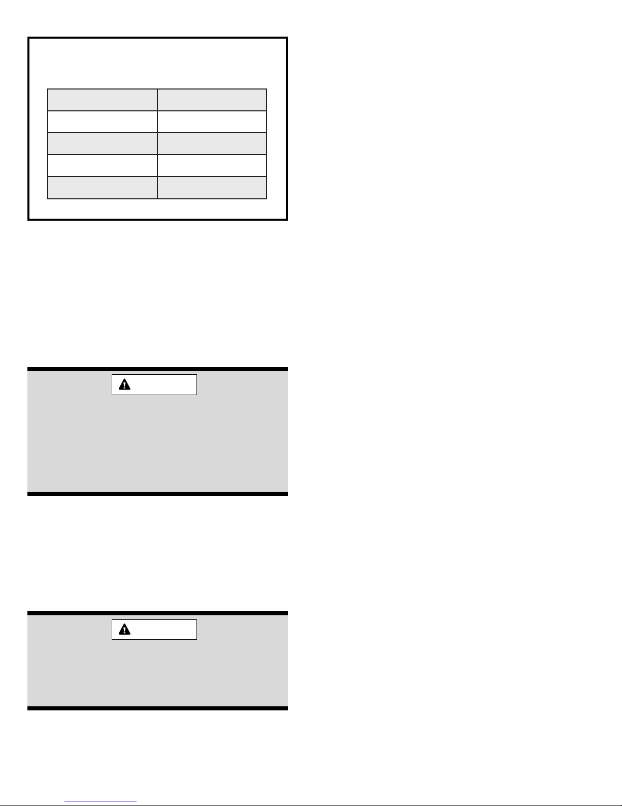
Unconfined Space
Minimum Clearances to Combustibles
sediStinU "0
tinUforaeR"0
tinUfotnorF "2
epiPeulF"0
poTmunelP "1
Table 1
Counterflow Models section on page 15 for more
information on using the special base assembly.)
When a counterflow unit is installed on a combustible
floor, 1" clearance must be provided between the supply
duct and the floor.
Combustion and Ventilation Air
WARNING
An unconfined space is defined as “a space whose
volume is more than 50 cubic feet per 1000 BTU per hour
of the combined input rating of all appliances installed in
that space.” When a furnace is installed in an unconfined
space in a building, it can be assumed that the infiltration
will be sufficient to supply the required air. If the furnace is
installed in a ventilated attic or crawl space, it is assumed
that the infiltration is sufficient to supply the required air.
However, in a building of unusually tight construction,
additional outdoor air should be provided.
Confined Space
A confined space is defined as “a space whose volume is
less than 50 cubic feet per 1000 BTU per hour of the
combined input rating of all appliances installed in that
space.”
If the furnace is installed in a confined space within the
building and combustion air is taken from a heated space,
the combustion air and ventilating air must enter and leave
the space through two permanent openings of equal area.
One opening shall be located within 12" of the ceiling and
the other within 12" of the floor, each having a free area of
1 square inch per 1000 BTU/HR of total input rating of all
appliances within the space and not less than 100 square
inches each.
Insufficient combustion air can cause headaches, nausea, dizziness, or asphyxiation.
When considering combustion air requirements, enough air must also be provided to
meet the needs of all fuel-burning appliances
and exhaust fans.
Adequate provisions for combustion air and ventilation of
furnace must be made. Refer to Section 5.3, “Air for
Combustion and Ventilation,” of the National Fuel Gas
Code, ANSI Z223.1/NFPA54 (latest edition), Sections 7.2,
7.3, or 7.4 of CSA B149.1 Natural Gas and Propane
Installation Codes (latest editions), or applicable provisions of the local building codes.
WARNING
Air openings in the front of the furnace must
be kept free of obstructions. Any obstruction
may cause improper operation that can result
in a fire hazard or carbon monoxide injury.
If the furnace is installed in a space within a building of tight
construction, makeup air must be supplied from outdoors. In
this case, one opening shall be within 12" of the ceiling and
one opening within 12" of the floor. If combustion ducts are
vertical, each opening shall have a free area of 1 square
inch per 4000 BTU/HR of the total input rating of all appliances within the enclosure. If horizontal combustion ducts
are run, 1 square inch per 2000 BTU/HR is required.
Contaminated Combustion Air
Excessive exposure to contaminated combustion air will
result in safety and performance related problems. The
recommended source of combustion air is outdoor air.
However, the use of indoor air in most applications is
acceptable if the following guidelines are followed:
1. If the furnace is installed in a confined space, it is
recommended that the necessary combustion air come
from the outdoors by way of an attic, crawl space, air
duct, or direct opening.
2. If indoor combustion air is used, there must be no
exposure to the substances listed in item 5.
3. All provisions for indoor combustion air must meet the
requirements for combustion air indicated in the
National Fuel Gas Code, ANSI Z223.1/NFPA 54
(latest edition), and/or any applicable local codes. In
# 45466K003Page 4
Page 5
Canada, see CSA B149.1, Natural Gas and Propane
Installation Codes (latest edition).
4. The following types of installation may require outdoor
air for combustion, due to chemical exposures:
• Commercial buildings
• Buildings with indoor pools
• Furnaces installed in laundry rooms
• Furnaces installed in hobby or craft rooms
• Furnaces installed near chemical storage areas
5. Exposure to the following substances in the combustion
air supply may also require outdoor air for combustion:
• Permanent wave solutions
• Chlorinated waxes and cleaners
• Chlorine-based swimming pool chemicals
• Water softening chemicals
• Deicing salts or chemicals
• Carbon tetrachloride
• Halogen-type refrigerants
• Cleaning solvents (such as perchloroethylene)
• Printing inks, paint removers, varnishes, etc.
• Cements and glues
• Antistatic fabric softeners for clothes dryers
• Masonry acid washing materials
• Chlorinated laundry products
• Hydrochloric acid
Venting
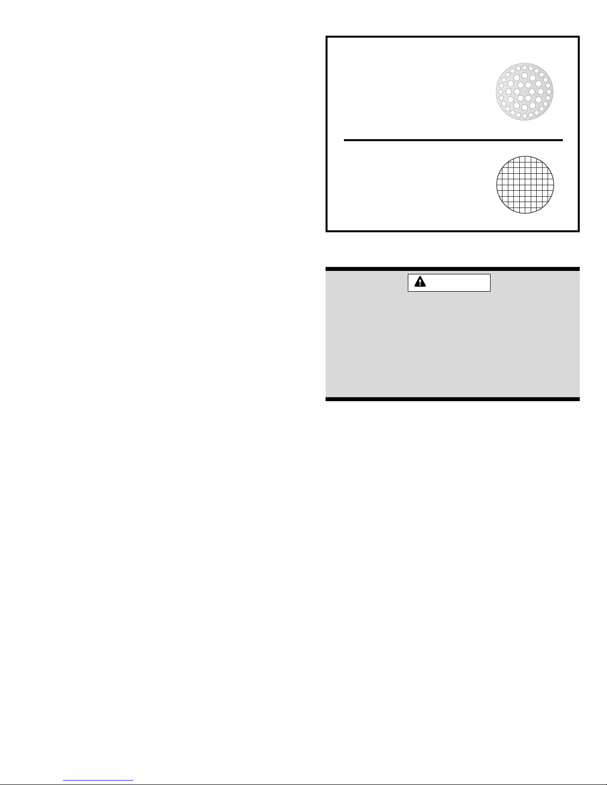
Inlet Air Restrictor Plate
The inlet air restrictor plate
must be installed in all
installations using inside air
for combustion (non-direct
vent).
Flue Pipe Screen
The flue pipe screen
should be installed at the
termination of the flue pipe
in all installations.
Figure 1
WARNING
If at any time in the future the installation of
this furnace is changed to require outside
fresh air for combustion, the inlet air restrictor
plate must be removed. Failure to remove the
inlet air restrictor could cause improper
operation that can result in a fire hazard or
carbon monoxide injury.
The high efficiency of this furnace is accomplished by the
removal of both sensible and latent heat from the flue gases.
The removal of latent heat results in the condensation of
moisture in the flue gases. This condensation occurs in the
secondary heat exchanger and in the vent system. Therefore, this furnace requires special venting considerations
and the instructions must be followed to insure proper
operation. All venting must be in accordance with the codes
having jurisdiction in the area and these instructions.
Upflow models G1D91BU, G1D93BU, and CG90UB and
counterflow models G1D93BC and CG90CB can be
installed as either direct vent or non-direct vent units. A
direct vent (two pipe) installation requires that all the air
necessary for combustion be supplied from outside the
dwelling through an air intake pipe. A non-direct vent (one
pipe) installation uses air from inside the dwelling for
combustion.
The furnace is shipped with the air inlet pipe terminated to
the top panel for either inside or outside combustion air. An
inlet air restrictor plate (see Figure 1) is supplied with this
furnace and can be found in the plastic bag containing these
Installation Instructions and the User’s Information Manual.
For installations using inside air for combustion (non-direct
vent), attach a 90° elbow (not supplied) to the inlet coupler
and install the restrictor plate inside the elbow (see Figures
8 and 9 on page 11 or Figures 13 and 14 on page 13).
Also included in the plastic bag containing the inlet air
restriction plate is a flue pipe screen (see Figure 1). In all
installations, this screen should be installed at the termination of the flue pipe and is designed to keep objects out
of the flue pipe.
For either type of installation (direct or non-direct vent),
special venting considerations must be followed. Refer to
the proper section in pages 10 – 13 for the type of furnace
and venting being installed.
The venting system must be supported with mounting
straps to prevent any weight load from being applied to the
vent blower. Horizontal vent pipe must be supported every
5' and vertical pipe should be supported every 10' to
prevent sagging and provide rigid support.
When a furnace is installed as direct vent, provisions for
ventilation air should follow the same requirements as if
installed as non-direct vent. Proper ventilation air is
necessary to maintain furnace component temperatures
within acceptable limits.
All vents passing through floors, ceilings, and walls must
be installed in accordance with National Fuel Gas Code,
ANSI Z223.1/NFPA 54 (latest edition).
# 45466K003 Page 5
Page 6
In all applications where the flue pipe is run through
an unconditioned space, 1/2" Armaflex or equivalent
must be used over the pipe. In extreme cold climates,
3/4" Armaflex is recommended.
Materials
cement is recommended. Metal or plastic strapping may be
used for vent pipe hangers.
When making ABS joints, pieces can be prepared with a
cleaner. When joining ABS to PVC materials, use PVC
solvent cement as specified in ASTM D3138.
All pipe, fittings, primer, and solvent cement must conform
with American National Standard Institute and the American Society for Testing and Materials (ANSI/ASTM)
standards. The solvent shall be free flowing and contain
no lumps, undissolved particles, or any foreign matter that
adversely affects the joint strength or chemical resistance
of the cement. The cement shall show no gelation, stratification, or separation that cannot be removed by stirring.
Refer to Table 2 for approved piping and fitting materials.
Piping and Fitting Specifications
gnittiFdnagnipiP
lairetaM
CVP04eludehcS
)epiP(
CVP04eludehcS
)epiPeroCralulleC(
CVP04eludehcS
)sgnittiF(
MTSA
noitacificepS
5871D
198F
6642D
Preferred fittings are DWV style or long sweep. Seal all joints
gas tight with appropriate cement. In areas where vent and
air intake pipes are exposed to abnormal stress or are
subject to damage, schedule 80 pipe should be used.
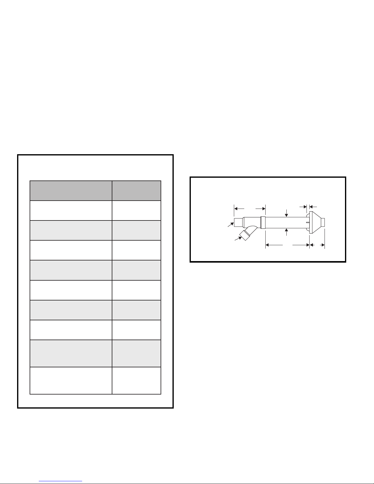
Concentric Vent Kit
A concentric vent kit (model ACVK2) is available for use
when installing this furnace as a direct vent furnace and the
air intake and vent pipe are to be run through the same hole,
whether horizontally through the wall or vertically through the
roof (see Figure 2). Refer to the instructions included with
the concentric vent kit for installation specifics.
Concentric Vent Kit Dimensions
1"
5"
2"
Nominal
Pipe Size
11"
3.5"
18"
62-RDS
)epiP(
SBA04eludehcS
)epiP(
SBA04eludehcS
)sgnittiF(
CVPC08&04eludehcS
)epiP(
1422D
7251D
8642D
144F
VWD-SBA
tneV&etsaWniarD
1662D
)sgnittiF&epiP(
VWD-CVP
tneV&etsaWniarD
5662D
)sgnittiF&epiP(
Table 2
The primers and solvents used must also meet ASTM
specifications. PVC primer is specified in ASTM F656. Use
PVC solvent as specified in ASTM D2564 and ABS solvent
cement as specified ASTM D2235. Low temperature solvent
Figure 2
Category IV Furnace Limitations
This furnace shall not be connected to any Type B, BW, or
L vent or vent connector and shall not be connected to
any portion of a factory-built or masonry chimney. This
furnace is not to be common vented with any other
appliance. The vent pipe must not be connected to a
chimney flue serving a separate appliance designed
to burn solid fuel.
Vent Pipe Size and Length
The vent pipe and air intake pipe (in direct vent installations) should be sized in accordance with the information
found in the appropriate table in Figure 3. One 90° elbow
is equivalent to 5' of pipe. Two 45° elbows are equivalent
to one 90° elbow. The minimum length certified for use
with this furnace is 5' and one elbow, not including the
vent and air intake terminals.
In the event that the pipe length is in between the lengths
listed in the table, use the next larger length listed. For
example, if a length of pipe needed to install the furnace is
27', use the diameter values for the 30' row in the tables.
# 45466K003Page 6
Page 7
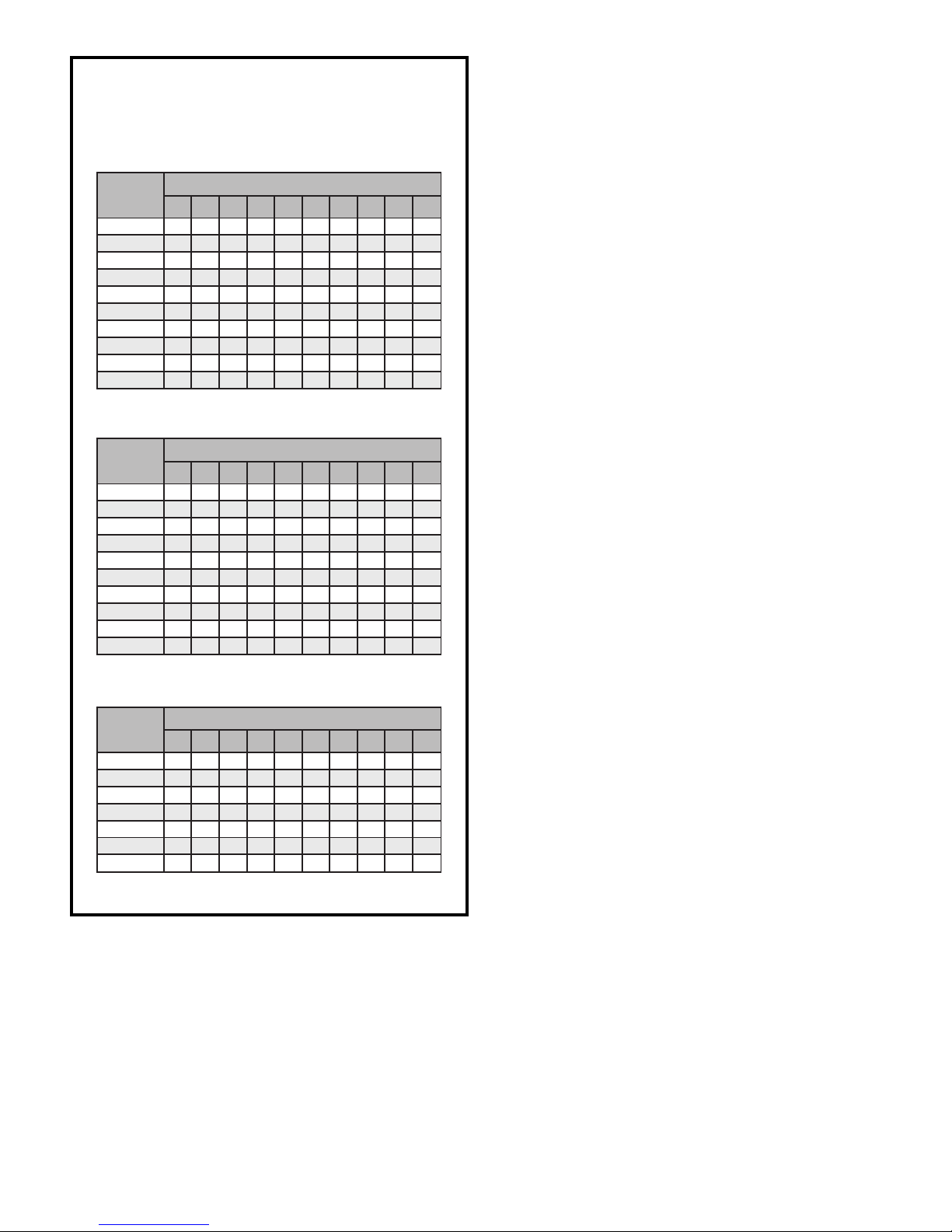
Horizontal Venting
Vent Tables
(numbers in inches unless specified otherwise)
Minimum Pipe Diameter
40,000 – 80,000 BTU/HR Models
epiPtneV
htgneL
0 1 2 3 4 5 6 7 8 9
).tf(
5
01
02
03
04
05
06
07
08
09
5
01
02
03
04
05
06
07
08
09
5.15.1 22222222
5.1 2 2 2 2 2 2 2 2 2
222222222 5.2
2 2 2 2 2 2 2 5.2 5.2 5.2
22222 5.25.25.25.25.2
2 2 5.2 5.2 5.2 5.2 5.2 5.2 5.2 3
25.25.25.25.25.25.2 333
5.2 5.2 5.2 5.2 5.2 3 3 3 3 RN
5.25.25.2 33333 RNRN
5.2 5.2 3 3 3 3 3 RN RN RN
Minimum Pipe Diameter
90,000 – 100,000 BTU/HR Models
epiPtneV
htgneL
0 1 2 3 4 5 6 7 8 9
).tf(
RN 222222 5.25.25.2
2 2 2 2 2 2 5.2 5.2 5.2 5.2
22222 5.25.25.25.23
2 2 2 5.2 5.2 5.2 5.2 3 3 3
22 5.25.25.2 33333
5.2 5.2 5.2 3 3 3 3 3 3 RN
5.2 333333 RNRNRN
3 3 3 3 3 RN RN RN RN RN
333 RNRNRNRNRNRNRN
3 3 RN RN RN RN RN RN RN RN
swoblE°09forebmuN
swoblE°09forebmuN
The vent for this appliance shall not terminate over public
walkways; or near soffit vents or crawl space vents or
other areas where condensate or vapor could create a
nuisance or hazard or cause property damage; or where
condensate vapor could cause damage or could be
detrimental to the operation of regulators, relief valves, or
other equipment.
See Figures 4 and 5 on pages 8 and 9 for additional
information on where the horizontal vent terminal can and
cannot terminate.
Minimum Pipe Diameter
112,000 – 125,000 BTU/HR Models
epiPtneV
htgneL
0 1 2 3 4 5 6 7 8 9
).tf(
5
01
02
03
04
05
06
NR = Not Recommended
5.25.25.25.25.25.25.25.25.25.2
5.2 5.2 5.2 5.2 5.2 5.2 5.2 5.2 5.2 3
5.25.25.25.25.25.25.233RN
5.2 5.2 5.2 5.2 5.2 3 3 RN RN RN
5.25.25.25.23RNRNRNRNRN
5.2 3 3 RN RN RN RN RN RN RN
33 RNRNRNRNRNRNRNRN
swoblE°09forebmuN
Figure 3
For direct vent installations, if the vent and air intake pipe
are not equal in length and number of elbows, then
determine the minimum pipe diameter for both the vent
and air intake. If the results indicate different diameters,
use the larger of the two for both the vent and air intake.
Under no circumstances should the vent and air
intake pipe size be different in diameter. For installation
details, refer to the appropriate section in pages 10 – 13
for the unit model and type of installation.
# 45466K003 Page 7
Page 8
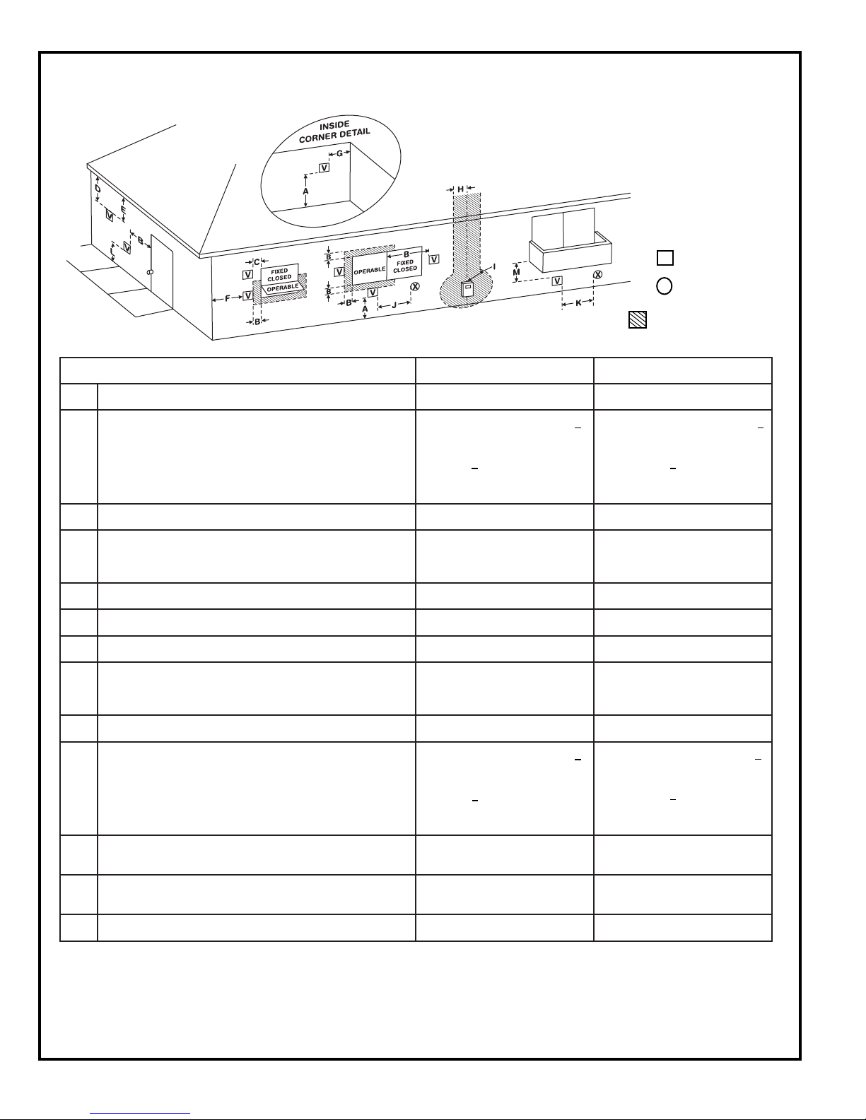
Sidewall Vent Terminal Clearances (Direct Vented Furnaces)
V
Vent Terminal
Air Supply Inlet
X
Area Where Terminal Is
Not Permitted
1
snoitallatsnInaidanaC
A
ynoclabro,kced,hcrop,adnarev,edargevobaecnaraelC )mc03(sehcni21)mc03(sehcni21
<secnailpparof)mc51(sehcni6
03(sehcni21,)Wk3(hutB000,01
B
denepoebyamtahtroodrowodniwotecnaraelC
3(hutB000,01>secnailpparof)mc
,)Wk03(hutB000,001<dna,)Wk
>secnailpparof)mc19(sehcni63
)Wk03(hutB000,001
C
wodniwdesolcyltnenamrepotecnaraelC **
2
snoitallatsnISU
<secnailpparof)mc51(sehcni6
32(sehcni9,)Wk3(hutB000,01
hutB000,01>secnailpparof)mc
51(hutB000,05<dna,)Wk3(
rof)mc03(sehcni21,)Wk
)Wk51(hutB000,05>secnailppa
ehtevobadetacoltiffosdetalitnevotecnaraelclacitreV
D
ehtmorf)mc16(teef2foecnatsidlatnozirohanihtiwlanimret
**
lanimretehtfoenilretnec
E
cnaraelC **
F
G
H
I
J
tiffosdetalitnevnuote
renrocedistuootecnaraelC **
renrocedisniotecnaraelC **
ylbmessarotaluger/retem
evobadednetxeenilretnecfoedishcaeotecnaraelC
51thgiehanihtiw)mc19(teef3
ehtevoba)m5.4(teef
*
ylbmessarotaluger/retem
teltuotnevrotalugerecivresotecnaraelC )mc19(teef3*
<secnailpparof)mc51(sehcni6
03(sehcni21,)Wk3(hutB000,01
ecnailpparehtoynaottelnirianoitsubmoc
ehtrognidliubottelniylppusrialacinahcemnonotecnaraelC
3(hutB000,01>secnailpparof)mc
,)Wk03(hutB000,001<dna,)Wk
>secnailpparof)mc19(sehcni63
)Wk03(hutB000,001
<secnailpparof)mc51(sehcni6
32(sehcni9,)Wk3(hutB000,01
hutB000,01>secnailpparof)mc
51(hutB000,05<dna,)Wk3(
rof)mc03(sehcni21,)Wk
)Wk51(hutB000,05>secnailppa
K
L
ytreporpcilbupno
M
1
In accordance with the current CSA B149.1, Natural Gas and
Propane Installation Code
2
In accordance with the current ANSI Z2223.1/NFPA 54, National
Fuel Gas Code
†
A vent shall not terminate directly above a sidewalk or paved
driveway that is located between two single family dwellings and
serves both dwellings.
telniylppusrialacinahcemaotecnaraelC )m38.1(teef6
detacolyawevirddevaproklawedisdevapevobaecnaraelC
ynoclabro,kced,hcrop,adnarevrednuecnaraelC )mc03(sehcni21*
‡
Permitted only if veranda, porch, deck, or balcony is fully open on a
†
)m31.2(teef7*
‡
01nihtiwfievoba)mc19(teef3
yllatnoziroh)m3(teef
minimum of two sides beneath the floor.
* For clearances not specified in ANSI Z2223.1/NFPA 54 or CSA
B149.1, the following statement shall be included:
“Clearance in accordance with local installation codes and the
requirements of the gas supplier and the manufacturer’s installation
instructions.”
Figure 4
# 45466K003Page 8
Page 9
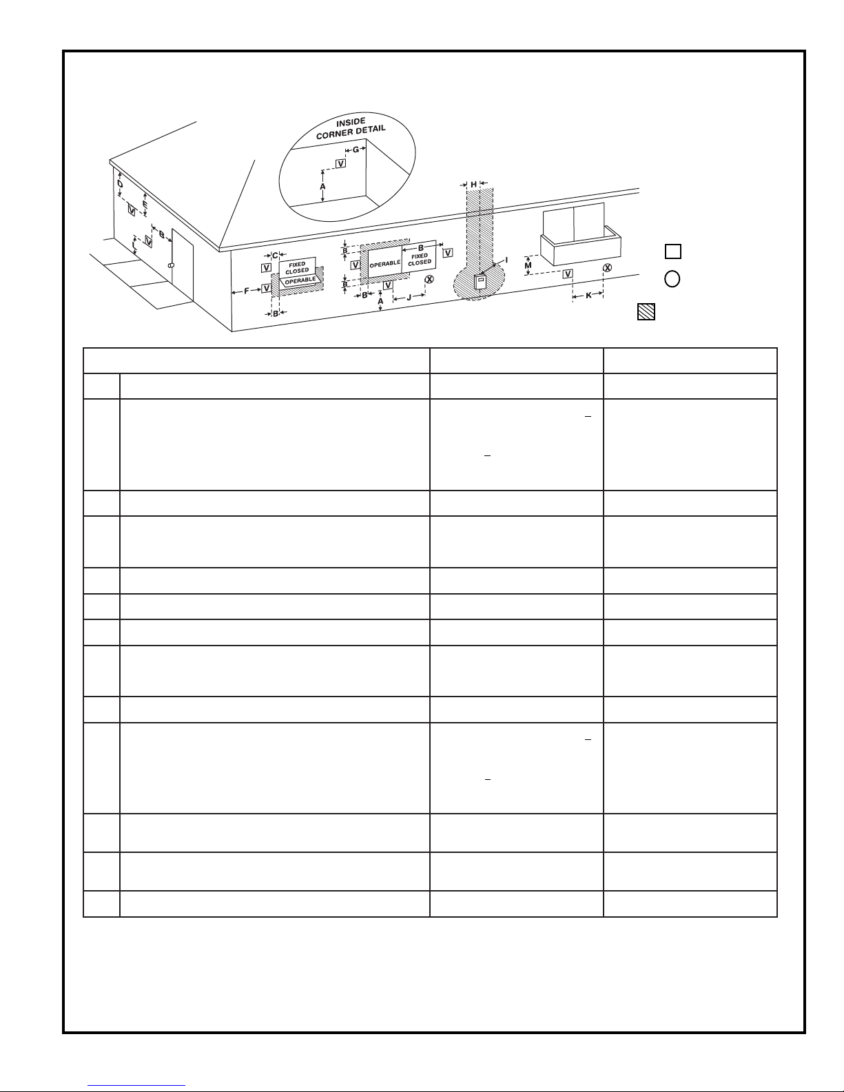
Sidewall Vent Terminal Clearances (Non-Direct Vented Furnaces)
V
X
Area Where Terminal Is
Not Permitted
Vent Terminal
Air Supply Inlet
1
snoitallatsnInaidanaC
A
ynoclabro,kced,hcrop,adnarev,edargevobaecnaraelC )mc03(sehcni21)mc03(sehcni21
2
snoitallatsnISU
<secnailpparof)mc51(sehcni6
03(sehcni21,)Wk3(hutB000,01
B
denepoebyamtahtroodrowodniwotecnaraelC
3(hutB000,01>secnailpparof)mc
,)Wk03(hutB000,001<dna,)Wk
>secnailpparof)mc19(sehcni63
gninepo
foedisotrowoleb)m2.1(teef4
evoba)m003(toof1;gninepo
)Wk03(hutB000,001
C
wodniwdesolcyltnenamrepotecnaraelC **
ehtevobadetacoltiffosdetalitnevotecnaraelclacitreV
D
ehtmorf)mc16(teef2foecnatsidlatnozirohanihtiwlanimret
**
lanimretehtfoenilretnec
E
F
G
H
I
tiffosdetalitnevnuotecnaraelC **
renrocedistuootecnaraelC **
renrocedisniotecnaraelC **
ylbmessarotaluger/retem
evobadednetxeenilretnecfoedishcaeotecnaraelC
51thgiehanihtiw)mc19(teef3
ehtevoba)m5.4(teef
*
ylbmessarotaluger/retem
teltuotnevrotalugerecivresotecnaraelC )mc19(teef3*
<secnailpparof)mc51(sehcni6
J
ecnailpparehtoynaottelnirianoitsubmoc
ehtrognidliubottelniylppusrialacinahcemnonotecnaraelC
3(hutB000,01>secnailpparof)mc
,)Wk03(hutB000,001<dna,)Wk
>secnailpparof)mc19(sehcni63
gninepo
03(sehcni21,)Wk3(hutB000,01
foedisotrowoleb)m2.1(teef4
evoba)m003(toof1;gninepo
)Wk03(hutB000,001
K
L
ytreporpcilbupno
M
1
In accordance with the current CSA B149.1, Natural Gas and
Propane Installation Code
2
In accordance with the current ANSI Z2223.1/NFPA 54, National
Fuel Gas Code
†
A vent shall not terminate directly above a sidewalk or paved
driveway that is located between two single family dwellings and
serves both dwellings.
# 45466K003 Page 9
telniylppusrialacinahcemaotecnaraelC )m38.1(teef6
detacolyawevirddevaproklawedisdevapevobaecnaraelC
ynoclabro,kced,hcrop,adnarevrednuecnaraelC )mc03(sehcni21*
‡
Permitted only if veranda, porch, deck, or balcony is fully open on a
†
)m31.2(teef7)m31.2(teef7
‡
01nihtiwfievoba)mc19(teef3
yllatnoziroh)m3(teef
minimum of two sides beneath the floor.
* For clearances not specified in ANSI Z2223.1/NFPA 54 or CSA
B149.1, the following statement shall be included:
“Clearance in accordance with local installation codes and the
requirements of the gas supplier and the manufacturer’s installation
instructions.”
Figure 5
Page 10

Upflow Models G1D91BU, G1D93BU, & CG90UB
Direct Vent Installation
slope upward, away from the furnace, at a minimum pitch of
1/4" per foot of run, to prevent accumulation of condensate.
An inlet air restrictor plate (see Figure 1 on page 5) is supplied
with this furnace and can be found in the plastic bag containing
these Installation Instructions and the User’s Information
Manual. This restrictor plate is to be used only in non-direct
vent applications. See the non-direct venting sections on
pages 11 and 13 for more information on installing the restrictor
plate in non-direct vent applications.
The flue pipe screen (see Figure 1 on page 5) should be
installed at the termination of the flue pipe and is designed
to keep objects out of the flue pipe. An additional screen
should not be placed in the intake termination. If a screen
is installed, the air intake may freeze shut.
Prime the trap system by slowly pouring 1 cup of water
down the vent pipe.
For horizontal venting, refer to Figure 6. For vertical venting,
refer to Figure 7. The vent pipe on horizontal runs must
Upflow Direct Vent – Horizontal Venting
(Models G1D91BU, G1D93BU,
& CG90UB Only)
RUN PITCH = 1/4”
PER FOOT MIN.
THIS PIECE
IS OPTIONAL.
Do not cement air intake into the connector on burner
box. Use high temperature RTV silicone sealant so
intake pipe can be removed if service is required.
For proper operation, the vent and air intake pipe
must be installed in the same pressure zone. Therefore, in horizontal venting applications they must be
on the same side of the house within the parameters
shown in Figure 6.
On initial start-up of the unit, some of the water used to
prime the trap system may run down into the combustion
blower and cause noise.
Upflow Direct Vent – Vertical Venting
(Models G1D91BU, G1D93BU,
& CG90UB Only)
SEE TABLE FOR
PROPER PIPE SIZE.
AIR INTAKE PIPE
CONDENSATE
COLLAR
THRU.
59.69/56.64
(CLOSED)
DRAINHOLE
* The 18" dimension is the minimum
recommended height for extremely
cold areas. In these areas,
moisture in the flue gases may
condense and freeze on the air
intake if this height is reduced. In
milder climates, this may be
reduced to a minimum of 6".
Height may be increased as
needed provided total length is not
exceeded.
FLUE PIPE
18” *
AIR INTAKE PIPE
6”
HEIGHT TO PROVIDE
12” CLEARANCE TO
MAX. SNOW LEVEL.
CAUTION
THE VENT SYSTEM OF
THE FURNACE MUST
BE SELF-SUPPORTING
AND
MUST NOT APPLYANY
WEIGHT LOAD TO THE
COMBUSTION
BLOWER.
IMPORTANT
DO NOT INSTALL THE
RESTRICTOR PLATES IN
ANY DIRECT VENT
APPLICATIONS.
Overhead View
FLUE PIPE
INTAKE PIPE
IS OPTIONAL.
3” MIN. - 48”MAX.
THIS PIECE
Figure 6
Figure 7
# 45466K003Page 10
Page 11

Upflow Models G1D91BU, G1D93BU, & CG90UB
Non-Direct Vent Installation
An inlet air restrictor plate (see Figure 1 on page 5) is
supplied with this furnace and can be found in the plastic
bag containing these Installation Instructions and the
User’s Information Manual. This restrictor plate is to be
used only in non-direct vent applications. Attach a 90°
elbow (not supplied) to the inlet coupler and install the
restrictor plate inside the elbow in all non-direct vent
installations (see Figures 8 and 9).
The flue pipe screen (see Figure 1 on page 5) should be
installed at the termination of the flue pipe and is designed
to keep objects out of the flue pipe.
Prime the trap system by slowly pouring 1 cup of water
down the vent pipe.
For horizontal venting, refer to Figure 8. For vertical
venting, refer to Figure 9. The vent pipe on horizontal runs
must slope upward, away from the furnace, at a minimum
pitch of 1/4" per foot of run, to prevent accumulation of
condensate.
On initial start-up of the unit, some of the water used to
prime the trap system may run down into the combustion
blower and cause noise.
Upflow Non-Direct Vent
Vertical Venting
(Models G1D91BU, G1D93BU,
& CG90UB Only)
Upflow Non-Direct Vent
(Models G1D91BU, G1D93BU,
CAUTION
THE VENT SYSTEM OF
THE FURNACE MUST BE
SELF-SUPPORTING AND
MUST NOT APPLY ANY
WEIGHT LOADTO THE
COMBUSTION BLOWER.
THE INLET AIR
RESTRICTOR PLATE
MUST BE INSTALLED
ON ALL NON-DIRECT
VENT INSTALLATIONS.
ATTACH A 90° ELBOW
TO THE INLET COUPLER
AND INSTALLTHE INLET
AIR RESTRICTOR PLATE
INSIDE THE ELBOW.
Horizontal Venting
& CG90UB Only)
RUN PITCH = 1/4
PER FOOT MIN.
SEE TABLE FOR
PROPER PIPE SIZE.
CONDENSATE
COLLAR
THRU.
59.69/56.64
(CLOSED)
DRAINHOLE
INLET
COUPLER
"
6"
HEIGHTTO PROVIDE
12 CLEARANCE TO
"
MAX. SNOW LEVEL.
Figure 8
# 45466K003 Page 11
Figure 9
Page 12

Counterflow Models G1D93BC & CG90CB Direct Vent
Installation
An inlet air restrictor plate (see Figure 1 on page 5) is supplied
with this furnace and can be found in the plastic bag containing
these Installation Instructions and the User’s Information
Manual. This restrictor plate is to be used only in non-direct
vent applications. See the non-direct venting sections on
pages 11 and 13 for more information on installing the restrictor
plate in non-direct vent applications.
Do not cement air inlet pipe. Use high temperature
RTV silicone sealant so inlet pipe can be removed if
service is required.
For proper operation, the vent and air intake pipe
must be installed in the same pressure zone. Therefore, in horizontal venting applications they must be
on the same side of the house within the parameters
shown in Figure 10.
The flue pipe screen (see Figure 1 on page 5) should be
installed at the termination of the flue pipe and is designed
to keep objects out of the flue pipe. An additional screen
should not be placed in the intake termination. If a screen is
installed, the air intake may freeze shut.
Prime the trap system by slowly pouring 1 cup of water
down the vent pipe. For horizontal venting, refer to Figure 10.
For vertical venting, refer to Figure 11. The vent pipe on
horizontal runs must slope upward, away from the furnace, at a minimum pitch of 1/4" per foot of run, to prevent
accumulation of condensate.
Counterflow Direct Vent
Horizontal Venting
(Models G1D93BC & CG90CB Only)
CAUTION
THE VENT SYSTEM OF
THE FURNACE MUST BE
SELF-SUPPORTING AND
MUST NOT APPLY ANY
WEIGHT LOADTO THE
COMBUSTION BLOWER.
VENT PIPE
RUN PITCH = 1/4”
PER FOOT MIN.
SEE TABLE FOR
PROPER PIPE SIZE.
PVC COLLARS
AIR INLET
PIPE
THIS PIECE
IS OPTIONAL.
FLUE PIPE
18” *
AIR INTAKE PIPE
6”
HEIGHTTO PROVIDE
12” CLEARANCETO
MAX. SNOW LEVEL.
Counterflow Direct Vent – Vertical Venting
(Models G1D93BC & CG90CB Only)
CONDENSATE
COLLAR
(CLOSED)
THRU.
59.69/56.64
DRANHOLE
* The 18" dimension is the
minimum recommended height
for extremely cold areas. In
these areas, moisture in the
flue gases may condense and
freeze on the air intake if this
Overhead View
FLUE PIPE
height is reduced. In milder
climates, this may be reduced
to a minimum of 6". Height may
INTAKE PIPE
be increased as needed
provided total length is not
exceeded.
Figure 10
IMPORTANT
DO NOT INSTALLTHE
RESTRICTOR PLATES IN
ANY DIRECT VENT
APPLICATIONS.
THIS PIECE
IS OPTIONAL.
3” MIN. - 48”MAX.
Figure 11
The 45,000 and 67,000 BTU/HR G1D93BC models
contain an inlet air assembly that uses two 22.5° elbows
that attach separately from the straight inlet pipe. This
allows the inlet pipe assembly to be removed if needed for
service. Do not cement these elbows. Refer to Figure 12
for detail of this inlet air assembly.
On initial start-up of the unit, some of the water used to
prime the trap system may run down into the combustion
blower and cause noise.
# 45466K003Page 12
Page 13

G1D93BC
45,000 & 67,000 BTU/HR Units
STRAIGHT
INLET PIPE
22.5° ELBOWS
BURNER BOX
Figure 12
Counterflow Models G1D93BC & CG90CB Non-Direct
Vent Installation
An inlet air restrictor plate (see Figure 1 on page 5) is
supplied with this furnace and can be found in the plastic
bag containing these Installation Instructions and the
User’s Information Manual. This restrictor plate is to be
used only in non-direct vent applications. Attach a 90°
elbow (not supplied) to the inlet coupler and install the
restrictor plate inside the elbow in all non-direct vent
installations (see Figures 13 and 14).
Counterflow Non-Direct Vent
Vertical Venting
(Models G1D93BC & CG90CB Only)
Counterflow Non-Direct Vent
Horizontal Venting
(Models G1D93BC & CG90CB Only)
CAUTION
THE VENT SYSTEM OF
THE FURNACE MUST BE
SELF-SUPPORTING AND
MUST NOT APPLY ANY
WEIGHT LOADTO THE
COMBUSTION BLOWER.
GROMMET
VENT PIPE
CONDENSATE
COLLAR
RUN PITCH = 1/4
PER FOOT MIN.
SEE TABLE FOR
PROPER PIPE SIZE.
INLET
COUPLER
PVC COLLAR
(CLOSED)
THRU.
59.69/56.64
DRANHOLE
"
THE INLET AIR
RESTRICTOR PLATE
MUST BE INSTALLED
ON ALL NON-DIRECT
VENT INSTALLATI ONS.
ATTACH A 90° ELBOW
TO THE INLET COUPLER
AND INSTALLTHE INLET
AIR RESTRICTOR PLATE
INSIDE THE ELBOW.
6"
HEIGHTTO PROVIDE
12 CLEARANCE TO
"
MAX. SNOW LEVEL.
Figure 14
The flue pipe screen (see Figure 1 on page 5) should be
installed at the termination of the flue pipe and is designed
to keep objects out of the flue pipe.
Prime the trap system by slowly pouring 1 cup of water
down the vent pipe. For horizontal venting, refer to Figure
13. For vertical venting, refer to Figure 14. The vent pipe
on horizontal runs must slope upward, away from the
furnace, at a minimum pitch of 1/4" per foot of run, to
prevent accumulation of condensate.
# 45466K003 Page 13
Figure 13
On initial start-up of the unit, some of the water used to
prime the trap system may run down into the combustion
blower and cause noise.
Page 14

Existing Venting Systems
THRU.
59.69/56.64
1/2” NPT PLUG
(SUPPLIED)
1/2” NPT x 3/4” PVC ADAPTER
(SUPPLIED)
3/4” PVC
TEE MUST REMAIN
OPEN
When an existing furnace is removed or replaced, the
original venting system may no longer be sized to properly
vent the attached appliances. An improperly sized venting
system can result in spillage of flue products into the living
space, the formation of condensate, leakage, etc. See the
WARNING box below for proper test procedure.
Condensate Disposal Installation
Install the condensate drain line to the unit as follows. The
condensate can be drained from either the right or left
side of the furnace. Install the 1/2" NPT x 3/4" PVC
adapter (supplied) in the drain on the side that the draining
will occur. Install the plastic pipe plug opposite of the drain.
Using 3/4" PVC pipe, make a connection from the adapter
just installed to extend just outside the unit. Install a 3/4"
PVC tee as shown in Figure 15. From the tee, install the
drain to the disposal area. The top of the tee must be left
open for proper condensate drainage.
WARNING
Condensate Disposal
Figure 15
It is recommended that the condensate drain be routed
directly to a locally acceptable disposal area. The condensate drain line should not be run directly to the outdoors
especially in colder climates where temperatures may
cause the condensate to freeze in the drain line.
CARBON MONOXIDE POISONING HAZARD
Failure to follow the steps outlined below for each appliance connected to the venting system being placed into operation could result in carbon monoxide poisoning or death.
The following steps shall be followed for each appliance connected to the venting system being placed into operation,
while all other appliances connected to the common venting system are not in operation:
1. Seal any unused openings in the common venting system.
2. Visually inspect the venting system for proper size and horizontal pitch, as required in the National Fuel Gas Code,
ANSI Z223.1/NFPA 54 (latest edition) or the CSA B149.1 Natural Gas and Propane Installation Codes and these
instructions. Determine that there is no blockage or restriction, leakage, corrosion, or other deficiencies which could
cause an unsafe condition.
3. As far as practical, close all building doors and windows between the space in which the appliance(s) connected to the
venting system are located and other spaces in the building.
4. Close fireplace dampers.
5. Turn on clothes dryers and any appliance not connected to the venting system. Turn on any exhaust fans, such as
range hoods and bathroom exhausts, so they are operating at maximum speed. Do not operate a summer exhaust fan.
6. Follow the lighting instructions. Place the unit being inspected in operation. Adjust the thermostat so appliance is
operating continuously.
7. Test for spillage from draft hood equipped appliances at the draft hood relief opening after 5 minutes of main burner
operation. Use the flame of a match or candle.
8. If improper venting is observed during any of the above tests, the venting system must be corrected in accordance with
the National Fuel Gas Code, ANSI Z223.1/NFPA 54 (latest edition) and/or the CSA B149.1 Natural Gas and Propane
Installation Codes.
9. After it has been determined that each appliance remaining connected to the venting system properly vents when
tested as outlined above, return doors, windows, exhaust fans, fireplace dampers, and any other gas-fired burning
appliance to their previous conditions of use.
# 45466K003Page 14
Page 15

Circulating Air Supply
When the furnace is installed so that the supply ducts
carry air circulated by the furnace to areas outside the
space containing the furnace, the return air shall be
handled by a duct or ducts sealed to the furnace casing
and terminated outside the space containing the furnace.
Combustible Floor Installation
(Counterflow Models Only)
Base
Assembly
Furnace
A return air duct system is recommended. If the unit is
installed in a confined space or closet, a return connection
must be run, full size, to a location outside the closet. The
air duct in the closet must be tight to prevent any entrance
of air from the closet into the circulating air.
If there is no complete return air duct system, the return
air connection must be sealed to the furnace casing and
run, full size, to a location outside the utility room or space
housing the furnace to prevent a negative pressure on the
venting system.
CAUTION
When an air conditioning unit is used in conjunction with the furnace, the evaporator coil
must be installed in the discharge (supply) air.
Do not install an evaporator coil in the return
air; excessive condensation will occur within
the furnace.
Outlet Duct
Woven
Glass Tape
Combustible
Flooring
Figure 16
Duct
1"
For installations not equipped with a cooling coil, a removable access panel must be provided in the outlet duct. The
opening should be accessible when the furnace is placed
in service. Smoke or reflected light may be observed
inside the casing to indicate the presence of leaks in the
heat exchanger. The cover for the opening shall be
attached in such a manner as to prevent leaks. The
recommended opening size is 6" x 14" for all sizes.
Duct Connection – Counterflow Models
If a unit is installed on a noncombustible floor, it may be
installed directly over the supply duct or plenum. For installations on combustible flooring, a special base must be
ordered and used. (See the Accessories section on
page 24 for more information.) To install using the special
base assembly, see Figure 16 and the following instructions:
1. Cut a hole in the floor, sized to provide 1" clearance
between all four sides of the duct and the edge of the
flooring. The four angles on the base assembly should
recess into the floor joists and the base should rest on
all four outside flanges.
2. Construct duct connections with right angle flanges.
3. Drop the duct connections through the top of the base
assembly with the right angle flanges in good contact
with the glass tape on top of the base assembly.
4. Carefully position the furnace over the right angle duct
flanges.
Gas Supply and Piping
Refer to the furnace rating plate to make sure the furnace
is equipped to burn the gas supplied (natural or propane).
WARNING
Any conversion of a natural gas unit to propane gas must be done by qualified personnel using a conversion kit available from the
manufacturer, following the instructions in the
conversion kit. If done improperly, overfiring
of the burners and improper burner operation
can result. This can create carbon monoxide
which could cause asphyxiation.
# 45466K003 Page 15
Page 16

Gas supply piping should be installed in accordance with
local codes and the regulations of the utility. Piping must be
of adequate size to prevent undue pressure drop. Consult
the local utility or gas supplier for complete details on special
requirements for sizing gas piping.
If local codes allow the use of a flexible gas appliance
connector, always use a new listed connector. Do not use
a connector which has previously serviced another gas
appliance.
Pipe connections must be tight, and a non-hardening pipe
compound resistant to liquefied petroleum gases should
be used.
Connect the gas pipe to the furnace controls providing a
ground joint union as close to the controls as is possible to
facilitate removal of controls and manifold. Provide a drip
leg on the outside of the furnace. A manual shutoff valve
shall be installed in the gas line, outside the unit, 5' above
the floor, or in accordance with any local codes. A test
gauge connection must be installed with a 1/8" NPT
plugged tapping immediately upstream of the shutoff valve
(refer to Figure 17).
Gas Piping Connection
The furnace must be isolated from the gas supply piping
system by closing the individual manual shutoff valve
during any pressure testing of the gas supply piping
system at test pressure equal to or less than 1/2 psig
(3.5 kPa) or 14" W.C. If the piping system is to be tested at
pressures in excess of 1/2 psig (3.5 kPa), the furnace and
its appliance main gas valve must be disconnected from
the gas supply piping system.
WARNING
The gas valve supplied with this furnace is
rated at 1/2 psig maximum. Any higher pressure may rupture the pressure regulator
diaphragm and may cause overfiring of the
burners and improper burner operation. The
overfiring may result in the creation of carbon
monoxide which could cause asphyxiation.
After gas piping is complete, carefully check all piping
connections (factory and field) for gas leaks. Use a leak
detecting solution or other preferred means. Some soaps
used for leak detection are corrosive to certain metals.
Carefully rinse piping thoroughly after leak detection has
been completed.
Figure 17
WARNING
FIRE OR EXPLOSION HAZARD
Failure to follow the safety warnings exactly
could result in serious injury, death, or property damage.
Never test for gas leaks with an open flame.
Use a commercially available soap solution
made specifically for the detection of leaks to
check all connections. A fire or explosion may
result causing property damage, personal
injury, or loss of life.
# 45466K003Page 16
Page 17

Filter Rack Mounting Hole
Screw
Filter Rack
Corner Embossments
Front of Cabinet
Electrical Wiring
WARNING
Risk of electrical shock. Disconnect electrical
power at the circuit breaker or service panel
before making electrical connections. Failure
to disconnect power supplies can result in
property damage, personal injury, or death.
The furnace must be grounded and wired in accordance
with local codes or, in the absence of local codes, with the
National Electrical Code ANSI/NFPA No. 70 (latest edition)
and/or CSA C22.1 Electrical Code (latest edition) if an
external electrical source is utilized.
Filter Rack Installation
Figure 18
In all instances, other than wiring for the thermostat, the
wiring to be done and any replacement of wire shall
conform with the temperature limitation for Type T wire –
63°F (35°C) rise.
Connect a sufficiently sized wire with ground to the furnace’s
line voltage connections and ground lug. Refer to the
furnace rating plate for electrical characteristics to be used
in sizing field supply wiring and over-current protection.
The line voltage supply should be routed through a
readily accessible disconnect located within sight of the
furnace. A junction box on the furnace side panel is
provided for line voltage connections. Refer to the furnace
wiring diagram for specific connection information.
Proper polarity of the supply connections (“HOT”
and “NEUTRAL”) must be observed to ensure that
safety controls provide the protection intended.
A connection to the ground lug and actual earth ground
(typically a ground stake or buried steel pipe) must be
maintained for proper operation.
Bottom Filter Location
Upflow Models
Side
Base
Filter
Figure 19
2. Using the filter rack as a template, mark and drill four
7/64" diameter screw holes in the side panel(s).
3. With the filter access opening toward the front of the
furnace, use sheet metal screws to fasten the rack(s)
to the side panel(s).
The filter slides in the rack from the front of the unit. Install
the filter(s) with the mesh side towards furnace.
Filters
Filters are not supplied with CG90CB or CG90UB
series furnaces.
G1D91BU and G1D93BU Models
A filter rack and cleanable 16" x 25" x 1/2" filter are
supplied with the furnace. (Models designed for more than
1600 CFM nominal air delivery include two of each.) The
filter rack is to be installed between the return air duct and
the side of the furnace. Refer to Figure 18 and the following instructions to install the filter rack:
1. Using the corner embossments as a guide, mark and
cut a full-size opening in the side panel(s).
# 45466K003 Page 17
For units that do not include a side return filter rack, kit
AFILT524 can be used. Single side filter frame kit
AFILTHA7 is available for single side return air connection
in installations requiring more than 1600 CFM nominal air
delivery. Bottom return filter kit AFILT529 is also available
from the manufacturer.
Counterflow Models:
Filters are not supplied with these furnaces; however, filters
must be used. It is the installerís responsibility to install
properly sized filters in accordance with Table 3 on page 18.
Other filter accessories are also available from the manufacturer including a full line of indoor air quality products. For
information on these products, contact the local distributor.
Page 18

Minimum Filter Requirements
wolfriA
rotpircseD
90084
01 084
21675
41 276
61867
02 069
aerA.niM
).ni.qs(
1. The Airflow Descriptor is the two digits following
the “D” in the model number.
2. Areas and dimensions shown for cleanable filters
are based on filters rated at 600 feet per minute
face velocity.
3. Typical filter sizes are shown; however, any
combination of filters whose area equals or
exceeds the minimum area shown is satisfactory.
eziS
).ni(
52x02
52x02
02x61
02x02
02x02
52x02
sretliFelbasopsiD sretliFelbanaelC
.ytQ
1042
1 042
2882
2 633
2483
2 084
aerA.niM
.ni.qs()
eziS
).ni(
02x61
02x61
02x61
02x02
02x02
52x02
Electronic Air Cleaner
Terminals are provided on the blower control board for
connection of a 120-volt electronic air cleaner. The “EAC”
terminal is energized whenever the thermostat is calling
.ytQ
for heat, cooling, or continuous blower. Refer to the
furnace wiring diagram for specific connection information.
1
1
1
1
1
1
Twinning
The blower control board is designed to permit “twinning”
of furnaces (two furnaces connected to a common supply
and return air system, and controlled by one thermostat).
An accessory kit must be ordered from the manufacturer.
Specific wiring and operating instructions are included
with the kit.
Each furnace must have its own dedicated vent system.
Table 3
Thermostat
Install a room thermostat according to the instructions
furnished with it. Select a location on an inside wall that is
not subject to drafts, direct sunshine, or other heat
sources. The initial heat anticipator setting should be equal
to the total current draw of the control circuit.
Low voltage thermostat connections are to be made to the
blower control board as indicated on the wiring diagram.
Humidifier
Terminals are provided on the blower control board for
connection to a 120-volt humidifier. The “HUM” terminal is
energized whenever the thermostat calls for heat. Refer to
furnace wiring diagram for specific connection information.
Continuous Low Speed Blower
If continuous blower operation on low speed is desired,
connect the lowest speed motor tap to the “CONT”
terminal on the blower control board (refer to the furnace
wiring diagram.) The blower will operate on low speed
whenever main power is connected to the furnace, except
when it operates on heating or cooling speed during
thermostat call for heat or cooling. This constant air
terminal is intended for low speed only. If a motor is
wired for a higher speed, the increased amp draw could
cause the board control to fail and void the warranty.
# 45466K003Page 18
Page 19

START-UP
Lighting Instructions
For Your Safety, Read Before Operating
WARNING
If you do not follow these instructions exactly,
a fire or explosion may result causing property damage, personal injury, or loss of life.
These furnaces are equipped with an ignition device
which automatically lights the burners. Do not try to light
the burners by hand.
Before operating, smell all around the appliance area for
gas. Be sure to smell next to the floor because some gas
is heavier than air and will settle on the floor.
What to do if you smell gas:
• Do not try to light any appliances.
• Extinguish any open flame.
• Do not touch any electric switch; do not use any
phone in your building.
• Immediately call your gas supplier from a neighbor’s
phone. Follow the gas supplier’s instructions.
To Start Furnace:
CAUTION
Be sure the manual gas control has been in
the “OFF” position for at least 5 minutes
before starting the unit. Do not attempt to
manually light the burners.
1. Set the room thermostat to lowest setting.
2. Remove burner access door.
3. Move the gas control knob to the “ON” position. Use
only your hand to turn the gas control knob; never use
tools. If the knob will not turn by hand, don’t try to
repair it; call a qualified service technician. Force or
attempted repair may result in a fire or explosion.
4. Replace the burner access door.
5. Turn on the electrical power to the furnace.
6. Set the room thermostat to a point above room
temperature to light the main burners. After the
burners have ignited, set the room thermostat to
desired temperature.
To Shut Down Furnace:
1. Set the room thermostat to the lowest setting.
• If you cannot reach your gas supplier, call the fire
department.
Do not use this furnace if any part has been under water.
Immediately call a qualified service technician to inspect
the furnace and to replace any part of the control system
and gas control which has been under water.
IMPORTANT: Refer to the Lighting Instruction label on
the furnace for instructions on operating the specific
controls used on your unit.
2. Turn off all electric power to the furnace.
3. Remove burner access door.
4. Shut off the gas by moving the gas control knob to the
“OFF” position.
5. Replace the burner access door.
WARNING
Should overheating occur or the gas supply
fail to shut off, shut off the manual gas valve
to the appliance before shutting off the electrical supply.
# 45466K003 Page 19
Page 20

OPERATION
Sequence of Operation
cooling “off” delay, the control de-energizes the cooling
speed fan. At the end of the cooling “off” delay period, the
control returns to the standby mode.
Heating
During a call for heat the thermostat closes the R-W
circuit of the control board. The control board verifies limit
switches are closed and pressure switch is open. The
induced draft blower relay closes causing the blower to
run. As vent pressure is developed by the induced draft
blower, the pressure switch closes. After a 15-second prepurge, the control energizes the hot surface ignitor. After
the 7-second warmup time, the control energizes the main
gas valve causing the main burners to ignite. The hot
surface ignitor is de-energized 3 seconds after the main
valve opens. If flame is sensed during this time the main
valve remains energized and the control starts the
30-second heat blower “on” delay.
As heating demand is met, the thermostat de-energizes the
R-W circuit. The control de-energizes the main valve
causing the burners to shut off. The induced draft blower
shuts off after a 15-second post-purge delay. The circulating
air blower will continue to operate until the user-selectable
heat blower “off” delay expires. The control return to standby
mode once the heat blower “off” delay expires.
Fan “On”
During a fan “on” call, the thermostat energizes the R-G
circuit of the control board, immediately causing the fan to
energize the COOL speed. The fan remains energized as
long as the thermostat calls for fan “on” operation.
Controls
Following is a description of the operation of some of the
controls used in this furnace. All models use one of each
control, except as noted.
Pressure Switch
The pressure switch is a normally open switch that
monitors combustion air flow. Inadequate air flow resulting
from excessive venting system restriction or a failed
combustion blower will cause the switch to remain open.
Rollout Switch
The rollout switch is a normally closed switch that opens
when abnormal temperatures exist in the burner area. This
can be caused by a restricted heat exchanger causing
main burner flame to “roll out” into the vestibule area or
burner box.
This switch must be manually reset by pushing the button
on top to restore furnace operation. G1D93BC units have
two rollout switches.
Primary Limit Control
This is a normally closed control that opens if abnormally
high circulating air temperatures occur. It is an automatic
reset control.
If a call for cooling is energized during a fan “on” call, the fan
continues to operate at the COOL speed. If a call for heat is
energized during a fan “on” call, the control de-energizes the
fan immediately and begins the heat call/ignition sequence.
At the end of the fan “on” call the thermostat de-energizes
the R-G circuit of the control, causing the fan to be deenergized immediately.
Cooling
During a call for cooling, the thermostat energizes the R-Y
circuit of the control board. After a 1-second cooling “on”
delay, the control energizes the cooling fan speed. If the fan
is already energized, it remains running and does not deenergize for the 1-second cooling fan “on” delay.
The call for cooling has priority over continuous fan
operation while a call for heating has priority over both a
call for cooling or continuous fan. Ignition lockouts for any
reason do not affect cooling operation.
As cooling demand is met, the thermostat de-energizes
the R-Y circuit of the control board. After a 60-second
Auxiliary Limit Control
This is a normally closed control that opens under abnormal “reverse air flow” conditions that could occur in a
counterflow or horizontal installation if the circulating
blower fails. It is an automatic reset control.
Upflow models do not include an auxiliary limit control.
Interlock (Blower Door) Switch
When the blower door is removed, the interlock switch
breaks the power supply to the burner controls and blower
motor. The switch operation must be checked to confirm it
is operating correctly.
Blower Control Board
The blower control board operates the circulating air
blower, the combustion blower and any accessories
connected to it. These models feature user-selectable
blower “off” delay times (60, 90, 120, and 180 seconds)
that are factory set to provide a 120-second blower “off”
delay on heating (see wiring diagram on page 26).
# 45466K003Page 20
Page 21

Refer to the furnace wiring diagram while using the
following procedure to change motor speed:
1. Turn off electrical power to the unit.
2. Connect the desired speed tap for cooling on the
blower control board.
3. For heating speed, check the temperature rise and, if
necessary, adjust the blower speed tap to maintain
temperature rise within the range shown on the
furnace rating plate.
To use the same speed tap for both heating and
cooling, install a piggyback terminal on the speed tap
using a short jumper. Wire 1/4" quick connect terminals on both ends to jumper the “HEAT” and “COOL”
speed on the blower control board.
4. The remaining speed taps must be connected to
dummy terminals marked “PARK” on the blower
control board.
Checking and Adjusting Gas Input
The minimum permissible gas supply pressure for the
purpose of input adjustment is 5" W.C. for natural gas and
11" W.C. for propane gas. This furnace requires conversion
for use with propane (see Accessories section on page 24
for correct kit). The maximum inlet gas supply pressure is
10.5" W.C. for natural gas and 13" W.C. for propane.
Gas input must never exceed the value shown on the
furnace rating plate. The furnace is equipped for rated
input at manifold pressures of 3.5" W.C. for natural gas or
10.0" W.C. for propane gas.
To measure the manifold pressure, disconnect the hose
and remove the barbed fitting in the downstream side of
the gas valve and connect a water manometer or gauge
(see Figure 20).
To adjust the regulator, turn the adjusting screw(s) on the
regulator clockwise to increase pressure and input; counterclockwise to decrease pressure and input.
Replace the barbed fitting and reconnect the hose after
measuring and/or adjusting the regulator.
CAUTION
The furnace rate must be within +/- 2% of the
appliance rating input.
For Natural Gas: Check the furnace rate by observing the
gas meter, when available, making sure all other gas
appliances are turned off. The test hand on the meter
Checking and Adjusting Gas Input
Figure 20
should be timed for at least one revolution. Note the
number of seconds for one revolution.
Cubic Feet Per RevolutionBTU/HR
INPUT # Seconds Per Revolution
The heating value of the gas can be obtained from the local
utility company.
For Propane Gas: The only check for the furnace rate is to
properly adjust the manifold pressure using a manometer
and Table 4 on page 22. Typical manifold set point for
installations at altitudes from 0 to 4500 feet above sea level
is 10.0" W.C.
Temperature Rise
Check the temperature rise and, if necessary, adjust blower
speed to maintain temperature rise within the range shown
on the unit rating plate.
High Altitude
In both the United States and Canada, this furnace is
approved for operation at altitudes from 0 to 4500 feet above
sea level without any required modifications. From 4500 to
7500 feet, the gas manifold pressure needs to be adjusted
according to the information shown in Table 4 on page 22.
To adjust the manifold pressure, refer to previous section
Checking and Adjusting Gas Input. For installations
above 7500 feet, call Technical Service at 1-800-448-5872
ext. 2610 for assistance.
=
x 3600 x
Heating
Value
# 45466K003 Page 21
Page 22

Manifold Pressure vs. Altitude
saGlarutaN )PL(enaporP
edutitlA
).tf(
000284905.3872200.016669.0
0003 419 05.3 6912 00.01 9949.0
000418805.3611200.012339.0
0054 568 05.3 7702 00.01 9429.0
000594892.3930214.90098.0
0055 338 72.3 0002 53.9 0978.0
000681852.3469192.90868.0
0056 208 32.3 7291 42.9 0758.0
000778712.3198181.90648.0
0057 177 91.3 3581 21.9 0538.0
* Consult local utility for actual heating value.
Furnace Input = Input Factor x Nameplate Input
gnitaeH
*eulaV
3
tf/UTB(
)
dlofinaM
erusserP
).C.W.ni(
gnitaeH
*eulaV
3
tf/UTB(
)
dlofinaM
erusserP
.C.W.ni()
tupnItupnI
tupnItupnI
tupnI
rotcaFrotcaF
rotcaFrotcaF
rotcaF
Above 7500 feet, call Technical Services at 1-800448-5872 ext. 2610.
Table 4
# 45466K003Page 22
Page 23

MAINTENANCE
WARNING
ELECTRICAL SHOCK, FIRE,
OR EXPLOSION HAZARD
Failure to follow the safety warnings exactly
could result in dangerous operation, serious
injury, death, or property damage.
Improper servicing could result in dangerous
operation, serious injury, death, or property
damage.
• Before servicing, disconnect all electrical
power to furnace.
Main Burners
Light the burners and allow to operate for a few minutes to
establish normal burning conditions. Observe the main
burner flames. Compare this observation to Figure 21 to
determine if proper flame adjustment is present. Flame
should be predominantly blue in color and strong in appearance. Check that all burners are lit, and that the flame does
not impinge on the sides of the heat exchanger.
Distorted flame or yellow tipping of the natural gas main
burner flame, or long yellow tips on propane, may be
caused by lint accumulation or dirt inside the burner or
burner ports, at the air inlet between the burner and
manifold pipe, or obstructions over the main burner orifice.
Use a soft brush or vacuum to clean the affected areas.
• When servicing controls, label all wires prior
to disconnecting. Reconnect wires correctly.
• Verify proper operation after servicing.
It is recommended that this furnace be inspected by a
qualified service technician at the beginning of each
heating season.
Filters
Filters should be checked at least every 6 weeks. Disposable filters should be replaced when dirty, and cleanable
filters should be cleaned regularly. It is important to keep the
air filters clean, as dirty filters can restrict airflow and the
blower and induced draft motors depend upon sufficient air
flowing across and through them to keep from overheating.
Lubrication
The blower motor and induced draft motor are pre-lubricated
by the manufacturer and do not require further lubricating
attention. However, the motors should be cleaned periodically to prevent the possibility of overheating due to an
accumulation of dust and dirt on the windings or on the
motor exterior.
Typical Flame Appearance
(Main Burners)
Exchanger
Burner
Gas
Manifold
Burner
Flame
(Blue Only)
Figure 21
Heat
Condensate Collection and Disposal System
Check the condensate drain line periodically for blockage.
Visual inspection of condensate flow can be done easily
while the furnace is in operation. Use a flashlight to
illuminate the discharge end of the condensate drain that
is placed in the sewer opening. If the condensate drain
line becomes blocked or plugged, the furnace will not
operate properly.
# 45466K003 Page 23
Page 24

REPAIR PARTS
The following repair parts are available from the local
distributor. When ordering parts, include the complete
furnace model number and serial number which are
printed on the rating plate located on the furnace.
Control Group
Transformer
High limit control
Auxiliary limit (if used)
Gas valve
Ignition/blower control board
Flame sensor
Pressure switch
Blower door interlock switch
Combustion blower assembly
Flame rollout protector switch
Hot surface igniter
Heat Exchanger Group
Heat exchanger – primary
Heat exchanger – secondary
Condensate drain pan
Blower Group
Blower housing assembly
Blower wheel
Blower motor
Blower motor mount
Blower motor capacitor
Burner Group
Gas manifold
Main burner orifices
Main burners
Accessories
ALPKT572 Natural Gas to Propane Conversion Kit
(G1D91BU and CG90UB)
ALPKT574 Natural Gas to Propane Conversion Kit
(G1D93BU, G1D93BC, and CG90CB)
AFILTHA7 Single Side Filter Frame Kit
AFILT524 Side Return Filter Kit (upflow models)
AFILT529 Bottom Return Filter Kit
AFILT525 Return Filter Kit (counterflow models)
ANGKT557 Propane to Natural Gas Conversion Kit
(G1D91BU and CG90UB)
ANGKT556 Propane to Natural Gas Conversion Kit
(G1D93BU, G1D93BC, and CG90CB)
ATWIN579 Twinning Kit
ACVK2 Concentric Vent Kit
ABASE512 Combustible Floor Base (17.5" cabinets)
ABASE568 Combustible Floor Base (21.0" cabinets)
ABASE569 Combustible Floor Base (24.5" cabinets)
# 45466K003Page 24
Page 25

CONTROL SYSTEM DIAGNOSTICS
sutatSDEL noitpircseDtluaF
ffODEL
lortnocrolortnocotrewopoN
detcetedtluaferawdrah
nODEL noitarepolamroN
hsalF1ffoevlavsaghtiwtneserpemalF
sehsalF2
htiwdesolchctiwserusserP
fforecudni
sehsalF3
htiwnepohctiwserusserP
norecudni
sehsalF4 nepohctiwstimilhgiH
sehsalF5nepohctiwstuolloR
sehsalF6 tuokcolelcychctiwserusserP
sehsalF7noitingionoteudtuokcoL
sehsalF8
emalfynamoototeudtuokcoL
stuopord
sehsalF9gnisahpegatloveniltcerrocnI
Troubleshooting
The following visual checks should be made before
troubleshooting:
1. Check to see that the power to the furnace and the
blower control board is on.
2. The manual shutoff valves in the gas line to the
furnace must be open.
3. Make sure all wiring connections are secure.
4. Review the Sequence of Operation (see page 20).
Start the system by setting the thermostat above the room
temperature. Observe the system’s response. Then use
the information provided in this section to check the
system’s operation.
The furnace has a built-in, self-diagnostic capability. If a
system problem occurs, a fault code is shown by an LED
on the control board. The control continuously monitors its
own operation and the operation of the system. If a failure
occurs, the LED will indicate the failure code. The flash
codes are presented in Table 5.
Failure Codes
Fault Code History Button
The control stores the last five fault codes in memory. A
pushbutton switch is located on the control (see Figure 22
on page 26). When the pushbutton switch is pressed and
released, the control flashes the stored fault codes. The
most recent fault code is flashed first; the oldest fault code
is flashed last.
To clear the fault code history, press and hold the
pushbutton switch in for more than 5 seconds before
releasing.
Table 5
# 45466K003 Page 25
Page 26

Connection Diagram
P/N 45198-005
Figure 22
# 45466K003Page 26
Page 27

Schematic Diagram
P/N 45198-005
# 45466K003 Page 27
Figure 23
 Loading...