

Lennox CHP16-024, CHA16-030, CHA16-060, CHA16-036, CHP16-030 Service Manual
...
CHA/CHP16
Service Literature
Corp. 0109-L2
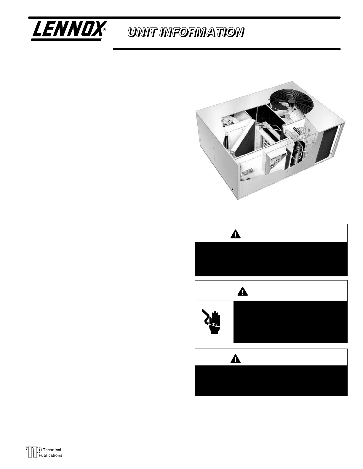
CHA/CHP16, CHP20 SERIES UNITS
CHA/CHP16 and CHP20 series units in the 2 through 5 ton
(7.0 through 17.6 kW) sizes are designed for outdoor roofĆ
top or ground level installations in light commercial applicaĆ
tions. Electric heat is available in several kW sizes. Models
are available in single or three phase power supply and can
be utilized in downflow or horizontal supply and return air.
CHA/CHP16-024/030 model units are equipped with a
reciprocating compressor. CHA/CHP16-036/060 and
CHP20-024/060 model units are equipped with scroll
compressors. The scroll compressor offers high voluĆ
metric efficiency, quiet operation and the ability to start
under system load. Continuous flank contact, mainĆ
tained by centrifugal force, minimizes gas leakage and
maximizes efficiency. The motor is internally protected
from excessive current and temperature.
CHA/CHP16 and CHP20 model units are designed to acĆ
cept any of several different thermostat control systems
with minimum field wiring. Control options such as econĆ
omizer, warm up kit, Honeywell T7300 thermostat or
Honeywell T8600/T8611/T8621 thermostat controls
connect to the unit with jackĆplugs. When plugged in the
controls become an integral part of the unit wiring. Low
voltage thermostat connections facilitate thermostat
field wiring.
Optional electric heat is field installed. Electric heat operĆ
ates in single or multiple stages depending on the kW size.
5kW through 25 kW sizes are available for the CHA/CHP16
and CHP20 units.
Information in this manual is for use by a qualified service
technicial only. All specifications in this manual are subject
to change. Procedures outlined in this manual are repesĆ
ented as a recommendation only and do not supersede or
replace state or local codes.
2 to 5 ton (7.0 to 17.6 kW)
CHP20
IMPORTANT
Improper installation, adjustment, alteration, service
or maintenance can cause property damage, personĆ
al injury or loss of life. Installation and service must
be performed by a qualified installer, service agency
or the gas supplier.
WARNING
Electric shock hazard. Can cause injury
or death. Before attempting to perform
any service or maintenance, turn the
electrical power to unit OFF at disconĆ
nect switch(es). Unit may have multiple
power supplies.
Page 1
WARNING
Refrigerant can be harmful if it is inhaled. Refrigerant
must be used and recovered responsibly.
Failure to follow this warning may result in personal
injury or death.
2001 Lennox Industries Inc.
Litho U.S.A.
TABLE OF CONTENTS
GENERAL 1. . . . . . . . . . . . . . . . . . . . . . . . . . . . . . . .
SPECIFICATIONS CHA16 3. . . . . . . . . . . . . . . . . .
SPECIFICATIONS CHP16 4. . . . . . . . . . . . . . . . .
SPECIFICATIONS CHP20 5. . . . . . . . . . . . . . . . . .
OPTIONAL ACCESSORIES CHA/CHP16 6. . . .
OPTIONAL ACCESSORIES CHP20 7. . . . . . . . .
ELECTRICAL DATA CHA16 8. . . . . . . . . . . . . . . .
ELECTRICAL DATA CHP16/20 9. . . . . . . . . . . . .
BLOWER DATA CHA16 10. . . . . . . . . . . . . . . . . . . .
BLOWER DATA CHP16/20 13. . . . . . . . . . . . . . . . .
ACCESSORIES BLOWER DATA 16. . . . . . . . . . . .
I APPLICATION 18. . . . . . . . . . . . . . . . . . . . . . . . . . . . . . .
ELECTROSTATIC DISCHARGE (ESD)
Precautions and Procedures
II UNIT COMPONENETS 18. . . . . . . . . . . . . . . . . . . . . .
Control Box 18. . . . . . . . . . . . . . . . . . . . . . . . . . . . . . .
Cooling Components 22. . . . . . . . . . . . . . . . . . . . . . .
Condenser Fan and Indoor Blower 27. . . . . . . . . . .
III OPTIONAL ELECTRIC HEAT 28. . . . . . . . . . . . . . . .
IV PLACEMENT AND INSTALLATION 43. . . . . . . . . . .
V ELECTRICAL CONNECTIONS 43. . . . . . . . . . . . . . .
VI START UP 43. . . . . . . . . . . . . . . . . . . . . . . . . . . . . . . . .
VII COOLING SYSTEM SERVICE CHECKS 43. . . . . .
VIII HEATING SYSTEM SERVICE CHECKS 44. . . . . .
IX INDOOR BLOWER OPERATION 44. . . . . . . . . . . . .
X MAINTENANCE 45. . . . . . . . . . . . . . . . . . . . . . . . . . . . .
XI ACCESSORIES 46. . . . . . . . . . . . . . . . . . . . . . . . . . . .
XII WIRING AND OPERATION SEQUENCE 52. . . . . .
CAUTION
Electrostatic discharge can affect electronic
components. Take precautions during unit
installation and service to protect the unit's elecĆ
tronic controls. Precautions will help to avoid
control exposure to electrostatic discharge by
putting the unit , the control and the technician at
the same electrostatic potential. Neutralize elecĆ
trostatic charge by touching hand and all tools on
an unpainted unit surface, such as the blower
deck, before performing any service procedure.
Page 2
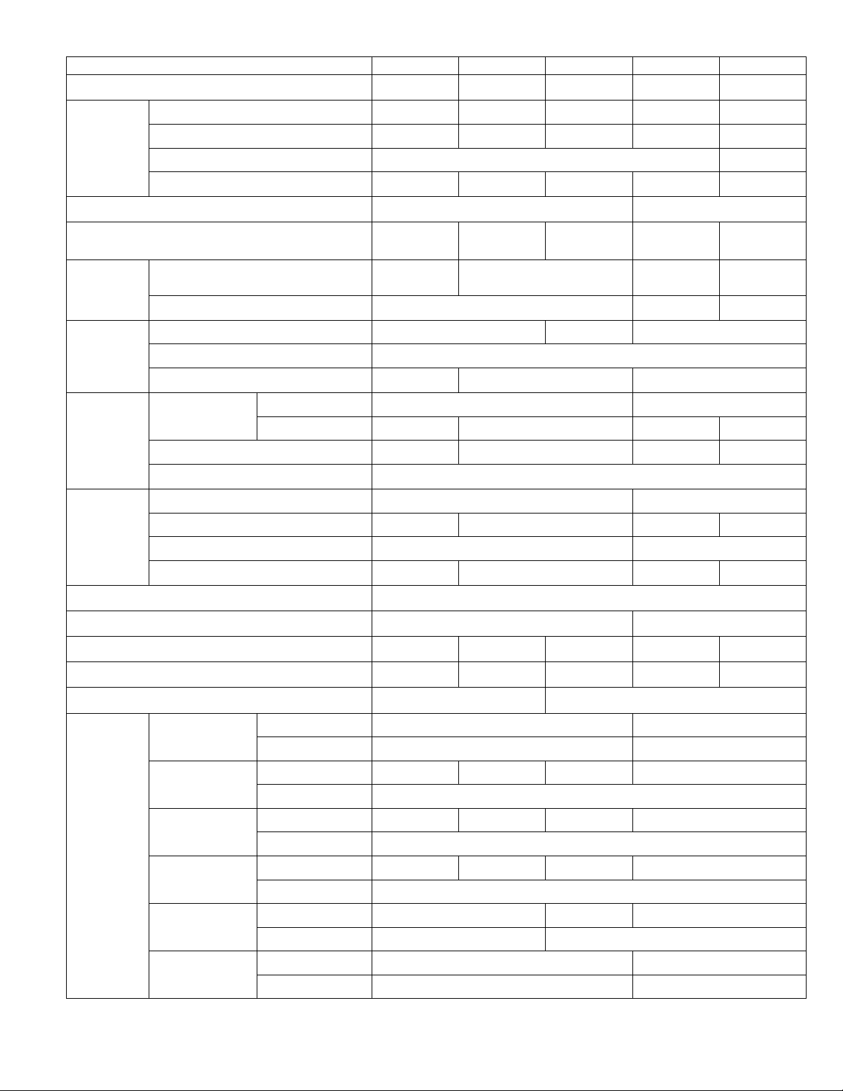
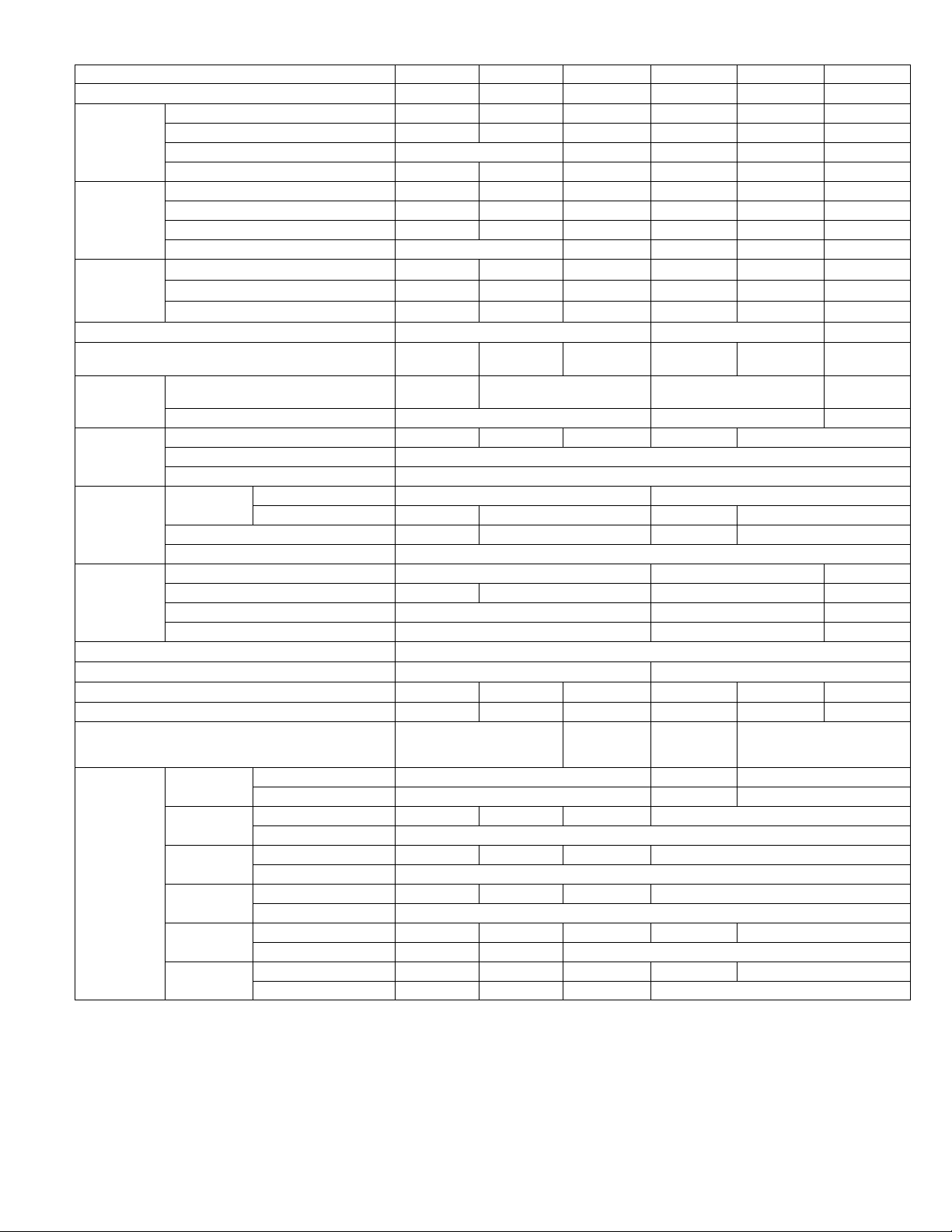
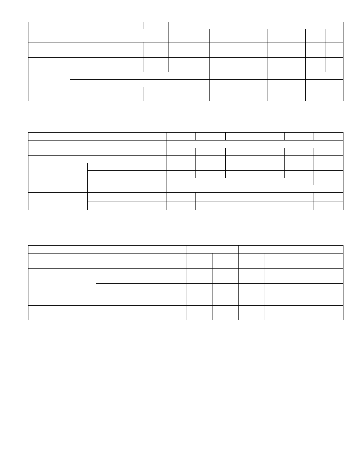
SPECIFICATIONS CHA16
Certified
g
Ratings
Coil
Net face area
Condenser
Condenser
ECH16R-5
ECH16R-7
ECH16R-10
Electric
g
Ratings
Model No. CHA16Ć024 CHA16Ć030 CHA16-036 CHA16-048 CHA16-060
Nominal Tonnage 2 2-1/2 3 4 5
Cooling capacity - Btuh (kW) 22,200 (6.5) 27,600 (8.1) 35,200 (10.3) 45,000 (13.2) 57,000 (16.5)
LARI
Certified
Cooling
Ratin
*Sound Rating Number (db) 80 82
Total unit watts 2550 3210 4045 4890 6065
SEER (Btuh/Watts) 10.0 10.25
s
EER (Btuh/Watts) 8.7 8.6 8.7 9.2 9.4
Refrigerant Charge (HCFC-22)
Blower wheel nominal
Evaporator
Blower
Evaporator
Coil
Condenser
Coil
Condenser
Fan
Condensate drain size mpt - in. (mm) 3/4 (19)
No. & size of cleanable polyurethane filters - in. (mm) (1) 16 x 25 x 1 (406 x 635 x 25) (1) 20 x 25 x 1 (508 x 635 x 25)
diameter x width in. (mm)
Motor horsepower (W) 1/3 (249) 1/2 (373) 3/4 (560)
Net face area - ft.2 (m2) 3.2 (0.30) 4.1 (0.38) 5.8 (0.54)
Tube diameter - in. (mm) & No. of rows 3/8 (9.5) - 2
Fins per inch (m) 15 (591) 17 (669) 15 (591)
Net face area
ft.2 (m2)
Tube diameter - in. (mm) & No. of rows 3/8 (9.5) - 1 3/8 (9.5) - 2 3/8 (9.5) - 1.4 3/8 (9.5) - 2
Fins per inch (m) 20 (787)
Diameter - in. (mm) & No. of blades 20 (508) - 4 24 (610) - 4
Air volume - cfm (L/s) 2400 (1135) 2200 (1040) 4000 (1890) 3600 (1700)
Motor horsepower (W) 1/6 (124) 1/4 (187)
Motor watts 230 220 340 330
Outer coil 8.6 (0.80) 14.3 (1.33)
Inner coil - - - - 8.4 (0.78) 5.9 (0.55) 13.8 (1.28)
3 lbs. 3 oz.
(1.45 kg)
9 x 8
(229 x 203)
4 lbs. 6 ozs.
(1.98 kg)
10 x 7 (254 x 178)
4 lbs. 13 ozs.
(2.18 kg)
5 lbs. 8 oz.
(2.49 kg)
10 x 8
(254 x 203)
7 lbs. 7 oz.
(3.37 kg)
11-1/2 x 9
(292 x 229)
Net weight of basic unit - lbs. (kg) 300 (136) 331 (150) 320 (145) 438 (199) 473 (215)
Shipping weight of basic unit - lbs. (kg) 1 package 385 (175) 413 (187) 407 (185) 547 (248) 582 (264)
Electrical characteristics - (60hz) 208/230v - 1 phase 208/230v - 1 ph, 208/230v, 460v or 575v - 3 ph
ECH16R-5
ECH16-5
ECH16R-7
ECH16-7
s
ECH16R-10
ECH16-10
ECH16-15
ECH16-20
ECH16-25
Optional
Electric
Heat
Ratin
*Sound Rating Number in accordance with test conditions included in ARI Standard 270.
LRated in accordance with ARI Standard 210/240 and DOE 95_F (35_F) outdoor air temperature and 80_F (27_C) db/67_F (19_C) wb entering evaporator coil air.
lAnnual Fuel Utilization Efficiency based on DOE test procedures and FTC labeling regulations.
Output - Btuh (kW) 19,000 (5.6) - - - -
lA.F.U.E. 99.0% - - - -
Output - Btuh (kW) 26,000 (7.6) 27,000 (7.9) 26,000 (7.6) 27,000 (7.9)
lA.F.U.E. 99.0%
Output - Btuh (kW) 36,000 (10.5) 37,000 (10.8) 36,000 (10.5) 37,000 (10.8)
lA.F.U.E. 99.0%
Output - Btuh (kW) 53,000 (15.5) 54,000 (15.8) 53,000 (15.5) 54,000 (15.8)
lA.F.U.E. 99.0%
Output - Btuh (kW) - - - - 70,000 (20.5) 71,000 (20.8)
lA.F.U.E. - - - - 99.0%
Output - Btuh (kW) - - - - 88,000 (25.8)
lA.F.U.E. - - - - 99.0%
Page 3
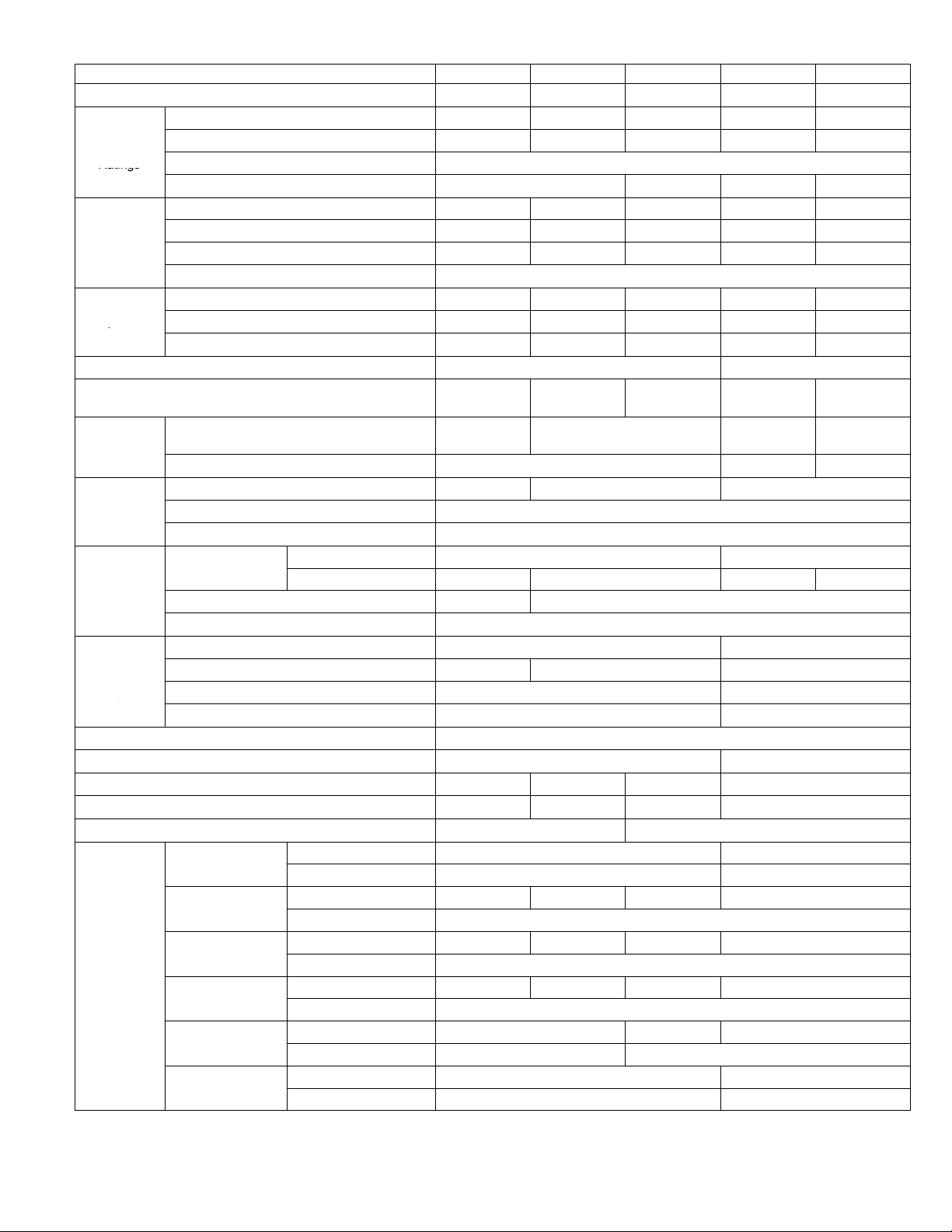
SPECIFICATIONS CHP16
C
Ratings
p
Temperature
Rati
LARI L
p
Coil
Net face area
Outdoor
C
Fan
ECH16R-5
ECH16R-7
ECH16R-10
Electric
Rati
Model No. CHP16Ć024 CHP16Ć030 CHP16-036 CHP16-048 CHP16-060
Nominal Tonnage 2 2-1/2 3 4 5
Cooling capacity - Btuh (kW) 23,800 (7.0) 29,000 (8.5) 34,600 (10.1) 46,500 (13.6) 55,000 (16.1)
LARI
ooling
Ratings
LARI High
Te m
erature
Heating
ngs
Temperature
Heating Ratings
*Sound Rating Number (db) 80 82
Refrigerant Charge (HCFC-22)
Indoor Coil
Blower
Indoor
Coil
Outdoor
Coil
Outdoor
oil
Fan
Condensate drain size mpt - in. (mm) 3/4 (19)
No. & size of cleanable polyurethane filters - in. (mm) (1) 16 x 25 x 1 (406 x 635 x 25) ( 1) 20 x 25 x 1 (508 x 635 x 25)
Net weight of basic unit - lbs. (kg) 332 (151) 340 (154) 354 (161) 535 (243)
Shipping weight of basic unit - lbs. (kg) 1 package 417 (187) 426 (193) 436 (198) 610 (277)
Electrical characteristics - (60hz) 208/230v - 1 phase 208/230v - 1 ph, 208/230v or 460v - 3 ph
Optional
Electric
Heat
ngs
*Sound Rating Number in accordance with test conditions included in ARI Standard 270.
LRated in accordance with ARI Standard 210/240;
Cooling Ratings - 95_F (35_F) outdoor air temperature and 80_F (27_C) db/67_F (19_C) wb entering indoor coil air
High Temperature Heating Ratings - 47 _F (8_C) db/43_F (6_C) wb outdoor air temperature and 70_F (21_C) entering indoor coil air
Low Temperature Heating Ratings - 17_F (-8_C) db/15_F (-9_C) wb outdoor air temperature and 70_F (21_C) entering indoor coil air.
Total unit watts 2615 3185 3870 4915 6225
SEER (Btuh/Watts) 10.0
EER (Btuh/Watts) 9.1 8.6 9.5 8.8
Total capacity - Btuh (kW) 23,800 (7.0) 29,400 (8.6) 35,800 (10.5) 49,500 (14.5) 57,500 (16.8)
Total unit watts 2235 2780 3430 4605 5765
C.O.P. (Coefficient of Performance) 3.12 3.10 3.06 3.14 2.94
HSPF - Region IV (Region V) 6.6 (5.9)
Total capacity - Btuh (kW) 12,800 (3.7) 17,000 (5.0) 22,800 (6.7) 28,000 (8.2) 33,600 (9.8)
ow
Total unit watts 1855 2330 3182 3800 5045
C.O.P. (Coefficient of Performance) 2.02 2.14 2.10 2.16 1.98
Blower wheel nominal diameter x width in. (mm)
5 lbs. 10 oz.
(2.55 kg)
9 x 8
(229 x 203)
6 lbs. 0 oz.
(2.72 kg)
10 x 7 (254 x 178)
7 lbs. 0 oz..
(3.18 kg)
10 lbs. 12 oz.
(4.88 kg)
10 x 8
(254 x 203)
Motor horsepower (W) 1/3 (249) 1/2 (373) 3/4 (560)
Net face area - sq. ft. (m2) 3.2 (0.30) 4.1 (0.38) 5.8 (0.54)
Tube diameter - in. (mm) & No. of rows 3/8 (9.5) - 3
Fins per inch (m) 15 (591)
Net face area
sq. ft. (m2)
Outer coil 8.6 (0.80) 14.3 (1.33)
Inner coil 5.3 (0.49) 8.3 (0.77) 9.9 (0.92) 13.8 (1.28)
Tube diameter - in. (mm) & No. of rows 3/8 (9.5) - 1.6 3/8 (9.5) - 2
Fins per inch (m) 20 (787)
Diameter - in. (mm) & No. of blades 20 (508) - 4 24 (610) - 4
Air volume - cfm (L/s) 2350 (1110) 2200 (1040) 3600 (1700)
Motor horsepower (W) 1/6 (124) 1/4 (187)
Motor watts 220 340
ECH16R-5
ECH16-5
ECH16R-7
ECH16-7
ECH16R-10
ECH16-10
Output - Btuh (kW) 19,000 (5.6) - - - -
lA.F.U.E. 99.0% - - - -
Output - Btuh (kW) 26,000 (7.6) 27,000 (7.9) 26,000 (7.6) 27,000 (7.9)
lA.F.U.E. 99.0%
Output - Btuh (kW) 36,000 (10.5) 37,000 (10.8) 36,000 (10.5) 37,000 (10.8)
lA.F.U.E. 99.0%
Output - Btuh (kW) 53,000 (15.5) 54,000 (15.8) 53,000 (15.5) 54,000 (15.8)
ECH16-15
lA.F.U.E. 99.0%
Output - Btuh (kW) - - - - 70,000 (20.5) 71,000 (20.8)
ECH16-20
lA.F.U.E. - - - - 99.0%
Output - Btuh (kW) - - - - 88,000 (25.7)
ECH16-25
lA.F.U.E. - - - - 99.0%
10 lbs. 5 oz.
(4.68 kg)
11-1/2 x 8
(292 x 203)
Page 4
SPECIFICATIONS CHP20
Cooli
g
Ratings
LARI Certified
High
p
Temperature
Bl
Coil
Net face area
Outdoor
Outdoor
ECH16RĆ5
ECH16RĆ7
Electric Heat
ECH16RĆ10
Model No
ECH16Ć15
ECH16Ć20
ECH16Ć25
Model No. CHP20Ć024 CHP20Ć030 CHP20Ć036 CHP20Ć042 CHP20Ć048 CHP20Ć060
Nominal Tonnage 2 2-1/2 3 3-1/2 4 5
Cooling Capacity Ċ Btuh (kW) 24,000 (7.0) 30,200 (8.8) 33,600 (9.8) 43,000 (12.6) 46,500 (13.6) 59,000 (17.3)
LARI
Ratin
High
Temperature
Heating Ratings
LARI Certified
Low
Te m
erature
Heating Ratings
*Sound Rating Number (db) 80 82 84
Refrigerant Charge (HCFCĆ22)
Indoor Coil
ower
Indoor
Outdoor
Coil
Outdoor
Coil Fan
Condensate drain size mpt Ċ in. (mm) 3/4 (19)
No. & size of cleanable polyurethane filters - in. (mm) (1) 16 x 25 x 1 (406 x 635 x 25) (1) 20 x 25 x 1 (508 x 635 x 25)
Net weight of basic unit Ċ lbs. (kg) 305 (138) 355 (161) 355 (161) 455 (206) 535 (243) 535 (243)
Shipping weight of basic unit Ċ lbs. (kg) (1 Pkg.) 390 (177) 419 (190) 419 (190) 525 (238) 610 (277) 610 (277)
Electrical characteristics (60 hz) 208/230v-1ph
Model No.
and
Ratings
*Sound Rating Number in accordance with test conditions included in ARI Standard 270.
lAnnual Fuel Utilization Efficiency based on DOE test procedures and FTC labeling regulations.
LCertified in accordance with the USE certification program, which is based on ARI standard 210/240.
Cooling RatingsĊ 95_F (35_C) outdoor air temperature and 80_F (27_C) db/67_F (19.5_C) wb entering indoor coil air.
High Temperature Heating RatingsĊ 47_F (8_C) db/43_F (6_C) wb outdoor air temperature and 70_F (21_C) entering indoor coil air.
Low Temperature Heating RatingsĊ 17_F (-8_C) db/15_F (-9_C) wb outdoor air temperature and 70_F (21_C) entering indoor coil air.
Total unit watts 2555 3145 3535 4105 4875 6325
ng
SEER (Btuh/Watts) 11. 0 11 .0 5 12.05 11. 00 11.05
s
EER (Btuh/Watts) 9.4 9.6 9.5 10.5 9.5 9.4
Total Capacity Ċ Btuh (kW) 24,200 (7.1) 29,800 (8.7) 34,200 (10.0) 41,500 (12.2) 48,500 (14.2) 62,500 (18.3)
Total unit watts 2245 2800 3000 3880 4695 6180
C.O.P 3.16 3.12 3.34 3.20 3.04 2.98
HSPF Ċ Region IV (Region V) 6.60 (5.90) 7.35 (5.70) 7.15 (6.30) 7.55 (6.70) 6.85 (6.05)
Total Capacity Ċ Btuh (kW) 14,800 (4.3) 18,600 (5.4) 21,400 (6.3) 26,200 (7.7) 31,600 (9.3) 38,600 (11.3)
Total unit watts 2085 2595 2725 3515 4225 5425
C.O.P 2.06 2.10 2.30 2.26 2.20 2.10
Blower wheel nominal diameter x width in. (mm)
5 lbs. 0 oz.
(2.27 kg)
9 x 8
(229 x 203)
6 lbs. 8 oz.
(2.95 kg)
6 lbs. 7 oz.
(2.92 kg)
9 lbs. 12 oz.
(4.42 kg)
10 x 7 (254 x 178) 10 x 8 (254 x 203)
10 lbs. 8 oz.
(4.76 kg)
Motor output Ċ hp (W) 1/3 (249) 1/2 (373) 3/4 (560)
Net face area Ċ sq. ft. (m2) 3.2 (0.30) 4.1 (0.38) 4.1 (0.38) 5.8 (0.54) 5.8 (0.54)
Tube diameter - in. (mm) & No. of rows 3/8 (9.5) Ċ 3
Fins per inch (m) 15 (591)
Net face area
Ċ sq. ft. (m2)
Outer coil 8.6 (0.80) 14.3 (1.33)
Inner coil 5.3 (0.49) 8.3 (0.77) 9.9 (1.28) 13.8 (1.28)
Tube diameter - in. (mm) & no. of rows 3/8 (9.5) - 1.6 3/8 (9.5) Ċ 2 3/8 (9.5) - 1.7 3/8 (9.5) Ċ 2
Fins per inch (m) 20 (787)
Diameter Ċ in. (mm) & No. of blades 20 (508) Ċ 4 24 (610) Ċ 4 24 (610) - 3
Air Volume Ċ cfm (L/s) 2350 (1110) 2200 (1040) 3600 (1700) 4000 (1890)
Motor output Ċ hp (W) 1/6 (124) 1/4 (187) 1/3 (249)
Motor watts 220 340 430
208/230v-1ph
208/230v or
460v - 3ph
208/230v-1ph
208/230v-1ph
208/230v or 460v - 3ph
Output Ċ Btuh (kW) 19,000 (5.6) Ć Ć Ć Ć Ć Ć Ć Ć
lA.F.U.E. 99.0% Ć Ć Ć Ć Ć Ć Ć Ć
Output Ċ Btuh (kW) 26,000 (7.6) 27,000 (7.9) 26,000 (7.6) 27,000 (7.9)
lA.F.U.E. 99.0%
Output Ċ Btuh (kW) 36,000 (10.5) 37,000 (10.8) 36,000 (10.5) 37,000 (10.8)
lA.F.U.E. 99.0%
.
ECH16RĆ7
ECH16Ć7
ECH16RĆ10
ECH16Ć10
Output Ċ Btuh (kW) 53,000 (15.6) 54,000 (15.8) 53,000 (15.6) 54,000 (15.8)
lA.F.U.E. 99.0%
Output Ċ Btuh (kW) Ć Ć Ć Ć Ć Ć Ć Ć 70,000 (20.5) 71,000 (20.8) 71,000 (20.8)
lA.F.U.E. Ć Ć Ć Ć Ć Ć Ć Ć 99.0%
Output Ċ Btuh (kW) Ć Ć Ć Ć Ć Ć Ć Ć Ć Ć Ć Ć 88,000 (25.7) 88,000 (25.8)
lA.F.U.E. Ć Ć Ć Ć Ć Ć Ć Ć Ć Ć Ć Ć 99.0%
10 lbs. 5 oz.
(4.68 kg)
11 x 8
(279 x 203)
Page 5
Model No. Ć024 Ć030 -036 -048 -060
yp
p
y
lated air dampers with pressure operated gravity
US
p, g
p
lizes filter furnished with unit, filter rack will accept
hood
ith cl
ly in cabinet, combination outdoor air and recircu
US
yg,p j
sensor, adjustable outdoor air enthalpy control. 1 in
(25 mm) fiberglass filter furnished, filter rack will
hood with alumi
filt
kit
()
p
y
damper assembly replaces blower access panel, manually
Economizer with Gravity Exhaust Dampers
(Down-Flow) Ċ Installs directly in cabinet, recircuĆ
lated air dam
exhaust damper, formed, gasketed damper blades,
nylon bearings, 24v damper motor has adjustable
minimum position switch, electronic discharge air
sensor, adjustable outdoor air enthalpy control. UtiĆ
lizes filter furnished with unit, filter rack will acce
up to 2 in. (51 mm) filter. Removable exhaust air
and outdoor air intake hood w
aluminum mesh filter. Choice of economizer conĆ
trols.
Economizer Dampers (Horizontal) Ċ Installs directĆ
lated air damper, formed, gasketed damper blades,
nylon bearings, 24v damper motor has adjustable
minimum position switch, electronic discharge air
(25 mm) fiberglass filter furnished, filter rack will
accept up to 2 in. (51 mm) filter, outdoor air intake
mizer controls.
Electric Heat Ċ Field installed, helix wound nichrome elements, time delay for eleĆ
ment staging, individual element limit controls, wiring harness, may be twoĆstage
controlled.
ECH16R - Supplemental thermal cutoff safety fuses and thermal
ECH16 - Supplemental secondary limits, heating control relay,
Electric Heat Single Point Power Source Sub-Fuse Box Ċ Use with ECH16R
electric heaters, use in conjunction with ECH16 fuse box for single point power
source applications, installs internal to unit, fuses furnished, constructed of galvaĆ
nized steel with prepunched mounting holes
Unit Single Point Power Source Sub Fuse Box Ċ Installs internal to unit, proĆ
vides sub-fusing to the unit, used in conjunction with ECH16 or ECH16R for single
point power source applications, fuses furnished, constructed of galvanized steel
with prepunched mounting holes and electrical inlet and outlet holes, hinged box
cover
Enthalpy Control, Differential Ċ Used in conjunction with outdoor air enthalpy
control. Determines and selects which air has the lowest enthalpy. Return air enĆ
thalpy sensor field installs in economizer damper section
Gravity Exhaust Dampers Ċ For use with EMDH16. Pressure operated assembly
field installs in the return air duct adjacent to the economizer assembly. Includes
bird screen. - Net Weight
Horizontal Filter Kit (Canada Only) Ċ For horizontal applications, painted steel
cabinet with filter access, disposable, pleated fiber filter furnished, number and
size of filter - Net Weight
Low Ambient Control Kit Ċ Units operate down to 30°F (-1°C) outdoor air temperĆ
ature in cooling mode without any additional controls. A Low Ambient Kit can be
field installed, enabling unit to operate properly down to 0°F (Ć17.7°C).
Roof Curb Power Entry Kit Ċ Allows power entry through
roof mounting frame, knockouts provided in roof frame,
contains 40 in. (1016 mm) armored conduit and installation
hardware, two kits are required, one for low voltage and one
for high voltage. See Dimension Drawing
Roof Mounting Frame Ċ Nailer strip furnished, mates to unit, U.S. National RoofĆ
ing Contractors Approved, shipped knocked down. RMF16-41 may be used on
all sizes, with a slight unit overhang on CHP16-048 and CHP16-060 units - Net
Weight
NOTE (US Only) Ċ Sound Reduction Plate must be ordered separately for field
installation.
Outdoor Air Damper Section Ċ For downĆflow applications,
dam
adjustable, 0 to 25% (fixed) outdoor air, outdoor air hood with
cleanable filter included, number and size of filter - Net Weight
Outdoor Air Damper Section Ċ For horizontal applications, installs in return air
duct adjacent to unit, manually adjustable (fixed) outdoor air - Net Weight
Outdoor Thermostat Kit Ċ Used to lock out some of the
electric heating elements on indoor units where two stage
control is applicable. Outdoor thermostat maintains the
heating load on the low power input as long as possible
before allowing the full power load to come on line
Indoor filter is not furnished with economizer. REMD16 utilizes existing filter furnished with 16 unit.
ers with pressure operated gravit
eanable
num mesh
relay sequencer.
fuse block, thermal relay sequencer (20-25 kW
208/230v) and galvanized steel control box.
er assembly replaces blower access panel, manuall
er. Choice of econoĆ
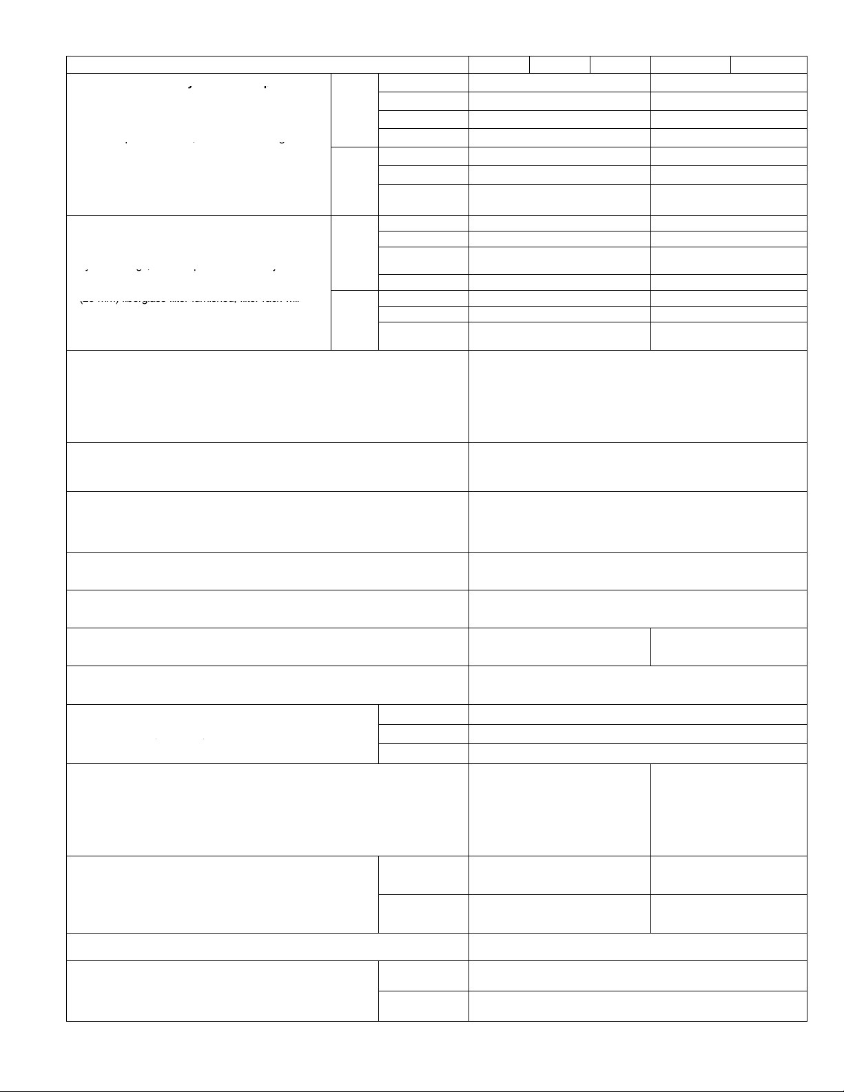
OPTIONAL ACCESSORIES CHA/CHP16
3 position REMD16-41 - 48 lbs. (22 kg) REMD16-65 - 66 lbs. (30 kg)
US
Only
t
Canada
Only
Ć
Ć
Only
Canada
Ć
Only
Fully Modulating REMD16M-41 - 48 lbs. (22 kg) REMD16M-65 - 66 lbs. (30 kg)
Indoor Filter (1) 16 x 25 x 1 (406 x 635 x 25) (1) 20 x 25 x 1 (508 x 635 x 25)
Outdoor Filter (1) 14 x 25 x 1 (356 x 635 x 25) (1) 18 x 25 x 1 (457 x 635 x 25)
Fully Modulating REMD16M-41S - 85 lbs. (39 kg) REMD16M-65S- 105 lbs. (48 kg)
Indoor Filter (1) 16 x 25 x 1 (406 x 635 x 25) (1) 20 x 25 x 1 (508 x 635 x 25)
Outdoor Filter (1) 19-3/8 x 15-3/4 x 1
3 position EMDH16-41 110 lbs. (50 kg) EMDH16-65 - 130 lbs. (59 kg)
Fully Modulating EMDH16M-41 - 110 lbs. (50 kg) EMDH16M-65 - 130 lbs. (59 kg)
Indoor Filter (1) 20 x 24 x 1 (508 x 610 x 25)
Outdoor Filter (1) 8 x 24 x 1 (203 x 610 x 25) (1) 8 x 28 x 1 (203 x 711 x 25)
Fully Modulating EMDH16M-41S - 70 lbs. (32 kg) EMDH16M-65S - 86 lbs. (39 kg)
Indoor Filter (1) 20 x 20 x 1 (508 x 508 x 25) (1) 20 x 25 x 1 (508 x 635 x 25)
Outdoor Filter
1/2 in. (13 mm) 18H70
1 in. (26 mm) 18H71
1-1/2 in. (39 mm) 18H72
US Only
Canada Only
Thermostat Kit LB-29740BA (56A87)
Mounting Box M-1595 (31461) / BM-10260 (33A09) Canada Only
(1) 16-1/2 x 21-3/4 x 1
HF16-46S - 18 lbs. (8 kg)
RMF16-41 - 75 lbs. (35 kg) 97G59
Plate (order separately) (73H80)
OAD16-41 - 12 lbs. (5 kg)
OAD16-41S - 10 lbs. (5 kg)
Page 6
(419 x 552 x 25)
See Electric Heat Data Tables
See Electric Heat Data Tables
See Electric Heat Data Tables
GEDH16-65 - 4 lbs. (2 kg)
(1) 20 x 20 x 2 in.
(508 x 508 x 51 mm)
CHP16 LB-57113BM (27J00)
CHA16 LB-57113BC (24H77)
(1) 5 x 17 x 1 in.
(127 x 432 x 25 mm)
(1) 14 x 6 x 1 in.
(356 x 152 x 25 mm)
OAD3-46/65 - 8 lbs. (4 kg)
(1) 19-7/8 x 22-3/4 x 1
(505 x 578 x 25)
(1) 16 x 25 x 1 (406 x 635 x 25)
(1) 14 x 25 x1 (356 x 635 x 1)
(1) 22-1/2 x 25-1/4 x 1
(571 x 641 x 25)
54G44
HF16-65S - 21 lbs. (10 kg)
(1) 20 x 25 x 2 in.
(508 x 635 x 51 mm)
RMF16-41 - 75 lbs. (35 kg)
OAD16-65 - 12 lbs. (5 kg)
OAD16-65S - 16 lbs. (7 kg)
97G59
Plate (order separately)
(73H80)
RMF16-65 - 86 lbs.
(39 kg) 97G60
Plate (order separately)
(73H82)
(1) 8 x 17 x 1 in.
(203 x 432 x 25 mm)
(1) 18 x 6 x 1 in.
(457 x 152 x 25 mm)
OPTIONAL ACCESSORIES CHA/CHP16 Cont.
nished, interior transition (even air flow), internally
transition (even air flow), internally sealed (prevents recirĆ
kit
()
Model No. Ć024 Ć030 -036 -048 -060
Coil Guards Ċ PVC coated steel wire guards to protect outdoor coil.
Compressor Monitor (Canada Only) Ċ NonĆadjustable switch (low ambiĆ
ent cutĆout) prevents compressor operation when outdoor temperature is
below 35°F (2°C).
Diffusers Ċ Aluminum grilles, large center grille, inĆ
sulated diffuser box with flanges, hanging rings furĆ
nished, interior transition (even air flow), internally
sealed (prevents recirculation), adapts to TĆbar ceilĆ
ing grids or plaster ceilings - Net Weight
Timed Off Control Ċ Prevents compressor shortĆcycling and allows time
for suction and discharge pressure to equalize, permitting the compressor
to start in an unloaded condition. Automatic reset control provides a time
delay between compressor shutoff and startĆup.
Transitions (Supply and Return) Ċ Used with diffusers, installs in roof
mounting frame, galvanized steel construction, flanges furnished for duct
connection, fully insulated - Net Weight
Unit Stand-Off Mounting Kit Ċ Elevates horizontal application units
above mounting surface. Includes six high impact polystyrene standĆoff
mounts. See dimension drawings.
StepĆDown -
double deflecĆ
tion louvers
Flush - fixed
blade louvers
OPTIONAL ACCESSORIES CHP20
Model No.
Coil Guards Ċ PVC coated steel wire guards to protect outdoor coil.
Diffusers Ċ Aluminum grilles, large center grille, insulated
diffuser box with flanges, hanging rings furnished, interior
transition (even air flow), internally sealed (prevents recirĆ
culation), adapts to TĆbar ceiling grids or plaster ceilings Net Weight
Economizer with Gravity Exhaust Dampers (Down-Flow) Ċ Installs directly in
cabinet, recirculated air dampers with pressure operated gravity exhaust dampĆ
er, formed, gasketed damper blades, nylon bearings, 3 position or fully moduĆ
lating 24v damper motor has adjustable minimum position switch, electronic
discharge air sensor, adjustable outdoor air enthalpy control. Utilizes filter furĆ
nished with unit, filter rack will accept up to 2 in. (51 mm) filter. Removable
exhaust air hood and outdoor air intake hood with aluminum mesh filter. Choice
of economizer controls. Model No. - Net Weight - No. & size of filter, in. (mm)
Economizer Dampers (Horizontal) Ċ Installs directly in cabinet, combination outĆ
door air and recirculated air damper, formed, gasketed damper blades, nylon
bearings, 3 position or fully modulating 24v damper motor has adjustable miniĆ
mum position switch, electronic discharge air sensor, adjustable outdoor air enĆ
thalpy control. 1 in (25 mm) fiberglass filter furnished, filter rack will accept up to 2
in. (51 mm) filter, outdoor air intake hood with aluminum mesh filter. Choice of
economizer controls. Model No. - Net Weight - No. & size of filter, in. (mm)
Electric Heat Ċ Field installed, helix wound nichrome elements, time delay for eleĆ
ment staging, individual element limit controls, wiring harness, may be twoĆstage
controlled.
ECH16R - Supplemental thermal cutoff safety fuses and thermal
ECH16 - Supplemental secondary limits, heating control relay,
Electric Heat Single Point Power Source Sub-Fuse Box Ċ Use with ECH16R elecĆ
tric heaters, use in conjunction with ECH16 fuse box for single point power source
applications, installs internal to unit, fuses furnished, constructed of galvanized steel
with prepunched mounting holes
Unit Single Point Power Source Sub Fuse Box Ċ Installs internal to unit, provides
sub-fusing to the unit, used in conjunction with ECH16 or ECH16R for single point
power source applications, fuses furnished, constructed of galvanized steel with
prepunched mounting holes and electrical inlet and outlet holes, hinged box cover
Enthalpy Control, Differential Ċ Used in conjunction with outdoor air enthalpy
control. Determines and selects which air has the lowest enthalpy. Return air enĆ
thalpy sensor field installs in economizer damper section
Gravity Exhaust Dampers Ċ For use with EMDH16. Pressure operated assembly
field installs in the return air duct adjacent to the economizer assembly. Includes
bird screen. - Net Weight
Low Ambient Control Kit - Units operate down to 30°F (-1°C) outdoor air temperaĆ
ture in cooling mode without any additional controls. A Low Ambient Kit can be field
installed, enabling unit to operate properly down to 0°F (Ć17.7°C).
Roof Curb Power Entry Kit Ċ Allows power entry through
roof mounting frame, knockouts provided in roof frame,
contains 40 in. (1016 mm) armored conduit and installaĆ
tion hardware, two kits are required, one for low voltage
and one for high voltage. See Dimension Drawing
relay sequencer.
fuse block, thermal relay sequencer (20-25 kW
208/230v) and galvanized steel control box.
StepĆDown -
double deflecĆ
tion louvers
Flush - fixed
blade louvers
1/2 in. (13 mm) 18H70
1 in. (26 mm) 18H71
1-1/2 in. (39 mm) 18H72
LB-82199CF (47J23)
2 guards per order
T6-1469 (45F08)
RTD9-65 - 67 lbs. (30 kg)
FD9-65 Ć 37 lbs.(17 kg)
LB-50709BK (47J27)
SRT16 - 20 lbs. (9 kg)
38H18
CHP20-024
CHP20-030
CHP20-036
LB-82199CF (47J23)
2 guards per order
RTD9-65 - 67 lbs. (30 kg)
FD9-65 Ć 37 lbs.(17 kg)
REMD16-41 - 48 lbs. (22 kg)
REMD16M-41 - 48 lbs. (22 kg)
EMDH16-41 - 110 lbs. (50 kg)
EMDH16M-41 - 110 lbs. (50 kg)
3 Position:
Modulating:
Indoor: (1) 16 x 25 x 1
(406 x 635 x 25)
Outdoor : (1) 14 x 25 x 1
(356 x 635 x 25)
3 Position:
Modulating:
Indoor : (1) 20 x 24 x 1
(508 x 610 x 25)
Outdoor : (1) 8 x 24 x 1
(203 x 610 x 25)
See Electric Heat Data Tables
See Electric Heat Data Tables
See Electric Heat Data Tables
GEDH16-65 - 4 lbs. (2 kg)
LB-57113BM (27J00)
LB-82199CG (47J24)
3 guards per order
CHP20-042
CHP20-048
LB-82199CG (47J24)
3 guards per order
REMD16-65 - 66 lbs. (30 kg)
REMD16M-65 - 66 lbs. (30 kg)
EMDH16-65 - 130 lbs. (59 kg)
EMDH16M-65 - 130 lbs. (59 kg)
(1) 14 x 25 x1 (356 x 635 x 1)
54G44
3 Position:
Modulating:
Indoor: (1) 20 x 25 x 1
(508 x 635 x 25)
Outdoor : (1) 18 x 25 x 1
(457 x 635 x 25)
3 Position:
Modulating:
Indoor : (1) 16 x 25 x 1
(406 x 635 x 25) &
Outdoor : (1) 8 x 28 x 1
(203 x 711 x 25)
CHP20-060
Page 7
OPTIONAL ACCESSORIES CHP20 Cont.
C
Condenser Coil
Evaporator
C
Condenser Coil
Evaporator
Model No. CHP20-024, -030, -036 CHP20-042, -048 CHP20-060
Roof Mounting Frame Ċ Nailer strip furnished, mates to unit, U.S. National
Roofing Contractors Approved, shipped knocked down. RMF16-41 may be
used on all sizes, with a slight unit overhang on CHP20-048 and CHP20-060
units - Net Weight. NOTE (US Only) Ċ Sound Reduction Plate must be ordered
separately for field installation.
Outdoor Air Damper Section Ċ For downĆflow applications, damper assembly reĆ
places blower access panel, manually adjustable, 0 to 25% (fixed) outdoor air, outĆ
door air hood with cleanable filter included, number and size of filter - Net Weight
Outdoor Air Damper Section Ċ For horizontal applications, installs in return
air duct adjacent to unit, manually adjustable (fixed) outdoor air - Net Weight
Outdoor Thermostat Kit Ċ Used to lock out some of the
electric heating elements on indoor units where two
stage control is applicable. Outdoor thermostat maintains
the heating load on the low power input as long as posĆ
sible before allowing the full power load to come on line
Timed Off Control Ċ Prevents compressor shortĆcycling and allows time for
suction and discharge pressure to equalize, permitting the compressor to start
in an unloaded condition. Automatic reset control provides a time delay beĆ
tween compressor shutoff and startĆup.
Transitions (Supply and Return) Ċ Used with diffusers, installs in roof mountĆ
ing frame, galvanized steel construction, flanges furnished for duct connection,
fully insulated - Net Weight
Unit Stand-Off Mounting Kit Ċ Elevates horizontal application units above
mounting surface. Includes six high impact polystyrene standĆoff mounts. See
dimension drawings.
Indoor filter is not furnished with economizer. REMD16 utilizes existing filter furnished with CHP20 unit.
Thermostat Kit LB-29740BA (56A87)
Mounting Box M-1595 (31461)
RMF16-41 - 75 lbs. (35 kg)
Plate (order separately) (73H80)
OAD16-41 - 12 lbs. (5 kg)
(1) 5 x 17 x 1 in.
(127 x 432 x 25 mm)
RMF16-41 - 75 lbs. (35 kg)
Plate (order separately) (73H80)
RMF16-65 - 86 lbs. (39 kg)
Plate (order separately) (73H82)
OAD16-65 - 12 lbs. (5 kg)
(1) 8 x 17 x 1 in.
(203 x 432 x 25 mm)
OAD3-46/65 - 8 lbs. (4 kg)
LB-50709BK (47J27)
SRT16 - 20 lbs. (9 kg)
38H18
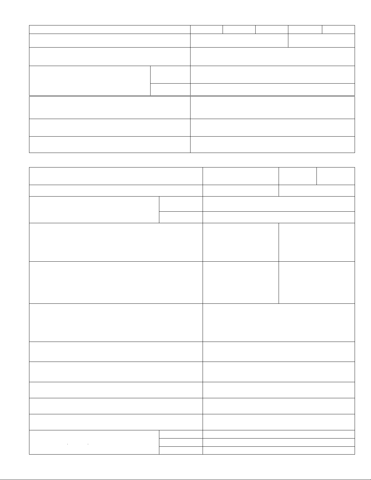
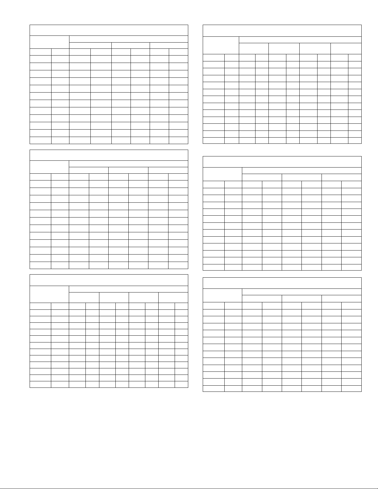
ELECTRICAL DATA CHA16
Single Phase
ModelĂNo. CHA16Ć024 CHA16Ć030 CHA16Ć036 CHA16Ć048 CHA16Ć060
LineĂvoltageĂdataĂ-Ă60Ăhz 208/230v - 1 phase
Recommended maximum fuse size (amps) 25 30 40 50 60
{Minimum Circuit Ampacity 16 21 27 34 41
ompressor
Condenser Coil
FanĂMotor
Evaporator
Blower Motor
{ReferĂtoĂNational or CanadianĂElectricalĂCodeĂmanualĂtoĂdetermineĂwire,ĂfuseĂandĂdisconnectĂsizeĂrequirements.
Where current does not exceed 100 amps, HACR type circuit breaker may be used in place of fuse (U.S. Only).
NOTEĂ-ĂExtremesĂofĂoperatingĂrangeĂareĂplusĂandĂminusĂ10%ĂofĂlineĂvoltage.
Rated load amps 10.1 13.0 17.7 21.8 26.1
Locked rotor amps 60 69.4 100.0 131.0 170
FullĂloadĂamps 1.1 2.3
LockedĂrotorĂamps 2.2 4.4
FullĂloadĂamps 2.2 3 3.9 5.2
LockedĂrotorĂamps 4.2 6.2 8.3 10
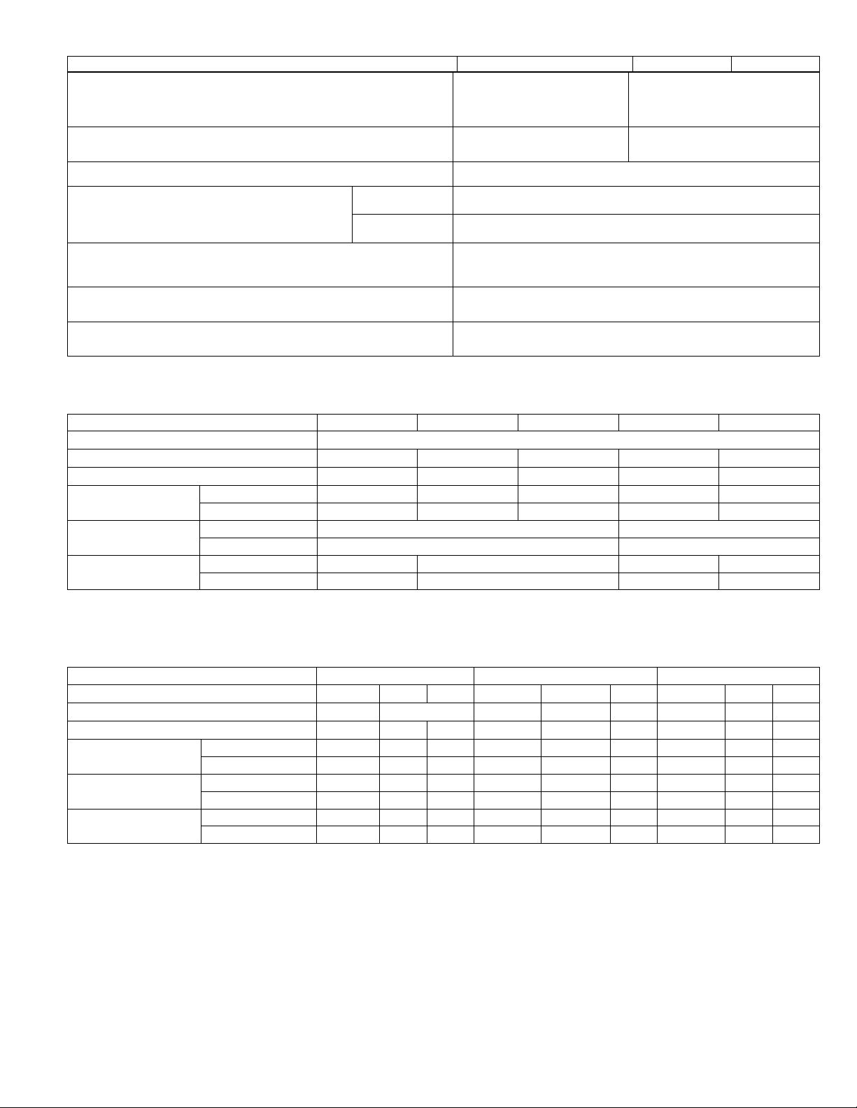
ELECTRICAL DATA CHA16
Three Phase
ModelĂNo. CHA16Ć036 CHA16Ć048 CHA16Ć060
LineĂvoltageĂdataĂ-Ă60Ăhz - 3 phase 208/230v 460v 575v 208/230v 460v 575v 208/230v 460v 575v
Recommended maximum fuse size (amps) 30 15 35 15 15 40 20 15
{Minimum Circuit Ampacity 20 11 9 23 11 10 28 14 12
ompressor
Condenser Coil
FanĂMotor
Evaporator
Blower Motor
{ReferĂtoĂNational or CanadianĂElectricalĂCodeĂmanualĂtoĂdetermineĂwire,ĂfuseĂandĂdisconnectĂsizeĂrequirements.
Where current does not exceed 100 amps, HACR type circuit breaker may be used in place of fuse (U.S. Only).
Motors are rated at 460 volts. Full load amps shown are for step-down transformer output.
NOTEĂ-ĂExtremesĂofĂoperatingĂrangeĂareĂplusĂandĂminusĂ10%ĂofĂlineĂvoltage.
Rated load amps 12.2 6.2 4.6 12.8 6.4 5.1 16.2 8.0 6.5
Locked rotor amps 77 39 31 91 46 37 124 60 47.7
FullĂloadĂamps 1.1 .73 .73 2.3 1.1 1.1 2.3 1.1 1.1
LockedĂrotorĂamps 2.2 1.3 1.3 4.4 2 2 4.4 2 2
FullĂloadĂamps 3.0 1.8 1.8 3.9 1.8 1.8 5.2 2.7 2.7
LockedĂrotorĂamps 6.2 4.4 4.4 8.3 4.4 4.4 10 3.8 3.8
Page 8
ELECTRICAL DATA CHP16
C
Outdoor Coil
Indoor Coil
C
Outdoor Coil
Bl
C
Outdoor Coil
Indoor Coil
ModelĂNo. Ć024 Ć030 Ć036 Ć048 Ć060
LineĂvoltageĂdataĂ-Ă60Ăhz 208/230v - 1 phase
Recommended max. fuse size (amps) 25 30 40 30 15 50 35 15 60 40 20
{Minimum Circuit Ampacity 16 21 27 20 11 34 23 11 39 27 13
ompressor
Outdoor Coil
FanĂMotor
Indoor Coil
Blower Motor
{ReferĂtoĂNational or CanadianĂElectricalĂCodeĂmanualĂtoĂdetermineĂwire,ĂfuseĂandĂdisconnectĂsizeĂrequirements.
Where current does not exceed 100 amps, HACR type circuit breaker may be used in place of fuse (U.S. Only).
NOTEĂ-ĂExtremesĂofĂoperatingĂrangeĂareĂplusĂandĂminusĂ10%ĂofĂlineĂvoltage.
Rated load amps 10.1 13.0 17.7 12.2 6.2 21.8 12.8 6.4 25.0 15.5 7.5
Locked rotor amps 60.0 69.4 100.0 77.0 39.0 131.0 91.0 46.0 170.0 124.0 60.0
FullĂloadĂamps 1.1 0.73 2.3 1.1 2.3 1.1
LockedĂrotorĂamps 2.2 1.3 4.4 2.0 4.4 2.0
FullĂloadĂamps 2.1 3.0 1.8 3.9 1.8 4.6 2.4
LockedĂrotorĂamps 4.2 6.2 4.4 8.3 4.4 10.0 3.8
208/230v
1 phase
208/230v
3 phase
460v -
3 phase
208/230v
1 phase
208/230v
3 phase
460v -
3 phase
208/230v
1 phase
208/230v
3 phase
3 phase
ELECTRICAL CHP20
Single Phase
CHP20 ModelĂNo. CHP20Ć024 CHP20Ć030 CHP20Ć036 CHP20Ć042 CHP20Ć048 CHP20Ć060
LineĂvoltageĂdata - 60 hz 208/230v
"RecommendedĂmaximumĂfuseĂsizeĂ(amps) 30 35 40 50 60 70
{MinimumĂCircuitĂAmpacity 19 22 25 32 36 44
ompressors
Outdoor Coil
FanĂMotor
Indoor Coil
ower Motor
(1 phase)
{ReferĂtoĂNationalĂor Canadian ElectricalĂCodeĂmanualĂtoĂdetermineĂwire,ĂfuseĂandĂdisconnectĂsizeĂrequirements.
"WhereĂcurrentĂdoesĂnotĂexceedĂ100Ăamps,ĂHACRĂtypeĂcircuitĂbreakerĂmayĂbeĂusedĂinĂplaceĂofĂfuse.
NOTEĂĊĂExtremesĂofĂoperatingĂrangeĂareĂplusĂandĂminusĂ10%ĂofĂlineĂvoltage.
RatedĂloadĂamps 12.2 13.8 16.1 20.1 23.7 28.8
LockedĂrotorĂamps 61.0 73.0 88.0 104.0 129.0 169.0
FullĂloadĂamps 1.1 2.3 2.4
LockedĂrotorĂamps 2.2 4.4
FullĂloadĂampsĂ 2.1 3.0 3.9 4.6
LockedĂrotorĂampsĂ 4.2 6.2 8.3 10.0
460v -
ELECTRICAL CHP20
Three Phase
CHP20 ModelĂNo. CHP20Ć036 CHP20Ć048 CHP20Ć060
LineĂvoltageĂdata - 60 hz - 3 phase 208/230v 460v 208/230v 460v 208/230v 460v
"RecommendedĂmaximumĂfuseĂsizeĂ(amps) 25 15 35 15 45 20
{MinimumĂCircuitĂAmpacity 17 10 24 13 29 15
ompressors
Outdoor Coil
FanĂMotor
Indoor Coil
Blower Motor (1 phase)
{ReferĂtoĂNationalĂor Canadian ElectricalĂCodeĂmanualĂtoĂdetermineĂwire,ĂfuseĂandĂdisconnectĂsizeĂrequirements.
"WhereĂcurrentĂdoesĂnotĂexceedĂ100Ăamps,ĂHACRĂtypeĂcircuitĂbreakerĂmayĂbeĂusedĂinĂplaceĂofĂfuse.
NOTEĂĊĂExtremesĂofĂoperatingĂrangeĂareĂplusĂandĂminusĂ10%ĂofĂlineĂvoltage.
RatedĂloadĂamps 10.3 5.2 13.5 7.4 17.3 9
LockedĂrotorĂamps 77 39 120 49.5 137 62
FullĂloadĂamps 1.1 0.73 2.3 1.1 2.4 1.3
LockedĂrotorĂamps 2.2 1.3 4.4 2 4.4 2.0
FullĂloadĂampsĂ 3 1.8 3.9 1.8 4.6 2.4
LockedĂrotorĂampsĂ 6.2 4.4 8.3 4.4 10 3.8
Page 9
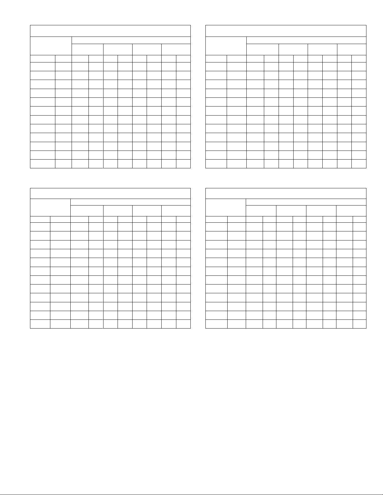
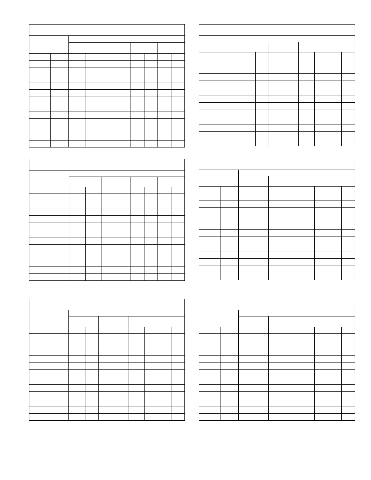
BLOWER DATA CHA16
CHA16-024 BLOWER PERFORMANCE
@ 230 VOLTS (With Down-Flow Air Openings)
External Static
Pressure
in. w.g. Pa cfm L/s cfm L/s cfm L/s cfm L/s
0 0 1370 645 950 450 875 415 660 310
.05 12 1365 645 955 450 880 415 670 315
.10 25 1350 635 960 455 885 420 675 320
.15 37 1340 630 960 455 885 420 680 320
.20 50 1320 625 955 450 880 415 680 320
.25 62 1300 615 950 450 875 415 680 320
.30 75 1280 605 940 445 870 410 675 320
.40 100 1220 575 920 435 850 400 660 310
.50 125 1150 545 880 415 820 385 630 295
.60 150 1070 505 835 395 775 365 585 275
.70 175 975 460 780 370 725 340 535 250
.75 185 925 435 745 350 700 330 500 235
NOTE Ċ For 208v unit operation, derate air volume by 7%. All air data is meaĆ
sured external to the unit with dry coil and without air filter.
Air Volume at Various Blower Speeds
High
MediumĆ
High
MediumĆ
Low
Low
CHA16-024 BLOWER PERFORMANCE
@ 230 VOLTS (With Horizontal Air Openings)
External Static
Pressure
in. w.g. Pa cfm L/s cfm L/s cfm L/s cfm L/s
Air Volume at Various Blower Speeds
High
MediumĆ
High
MediumĆ
Low
Low
0 0 1405 665 905 425 820 385 620 295
.05 12 1400 660 935 440 845 400 640 300
.10 25 1385 655 955 450 865 410 655 310
.15 37 1370 645 975 460 880 415 665 315
.20 50 1355 640 985 465 890 420 670 315
.25 62 1335 630 990 465 895 420 670 315
.30 75 1310 620 985 465 890 420 670 315
.40 100 1260 595 965 455 870 410 650 305
.50 125 1195 565 915 430 830 390 615 290
.60 150 1120 530 840 395 865 410 560 265
.70 175 1035 490 740 350 675 320 490 230
.75 185 990 465 685 325 620 295 445 210
NOTE Ċ For 208v unit operation, derate air volume by 7%. All air data is measured
external to the unit with dry coil and without air filter.
CHA16-030 BLOWER PERFORMANCE
@ 230 VOLTS (With Down-Flow Air Openings)
External Static
Pressure
in. w.g. Pa cfm L/s cfm L/s cfm L/s cfm L/s
Air Volume at Various Blower Speeds
High
MediumĆ
High
MediumĆ
Low
Low
0 0 1355 640 1255 590 1105 520 900 425
.05 12 1345 635 1250 590 1100 520 910 430
.10 25 1330 630 1245 590 1090 515 915 430
.15 37 1310 620 1235 585 1080 510 915 430
.20 50 1290 610 1220 575 1070 505 910 430
.25 62 1270 600 1205 570 1055 500 900 425
.30 75 1245 590 1180 555 1035 490 890 420
.40 100 1190 560 1130 535 990 465 855 405
.50 125 1125 530 1060 500 935 440 805 380
.60 150 1050 495 980 560 870 410 735 345
.70 175 960 455 885 420 790 375 655 310
.75 185 915 430 835 395 745 350 605 285
NOTE Ċ For 208v unit operation, derate air volume by 7%. All air data is measured
external to the unit with dry coil and without air filter.
CHA16-030 BLOWER PERFORMANCE
@ 230 VOLTS (With Horizontal Air Openings)
External Static
Pressure
in. w.g. Pa cfm L/s cfm L/s cfm L/s cfm L/s
Air Volume at Various Blower Speeds
High
MediumĆ
High
MediumĆ
Low
Low
0 0 1445 680 1330 630 1105 520 900 425
.05 12 1435 680 1295 610 1105 520 910 430
.10 25 1420 670 1285 605 1105 520 915 430
.15 37 1400 660 1275 600 1100 520 920 435
.20 50 1380 650 1265 595 1095 515 920 435
.25 62 1360 640 1250 590 1085 510 915 430
.30 75 1335 630 1230 580 1070 505 905 425
.40 100 1280 605 1185 560 1035 490 880 415
.50 125 1220 575 1135 535 995 470 840 395
.60 150 1150 545 1070 505 935 440 790 375
.70 175 1070 505 995 470 870 410 720 340
.75 185 1025 485 955 450 830 390 680 320
NOTE Ċ For 208v unit operation, derate air volume by 7%. All air data is measured
external to the unit with dry coil and without air filter.
Page 10
BLOWER DATA CHA16 Cont
External Static
External Static
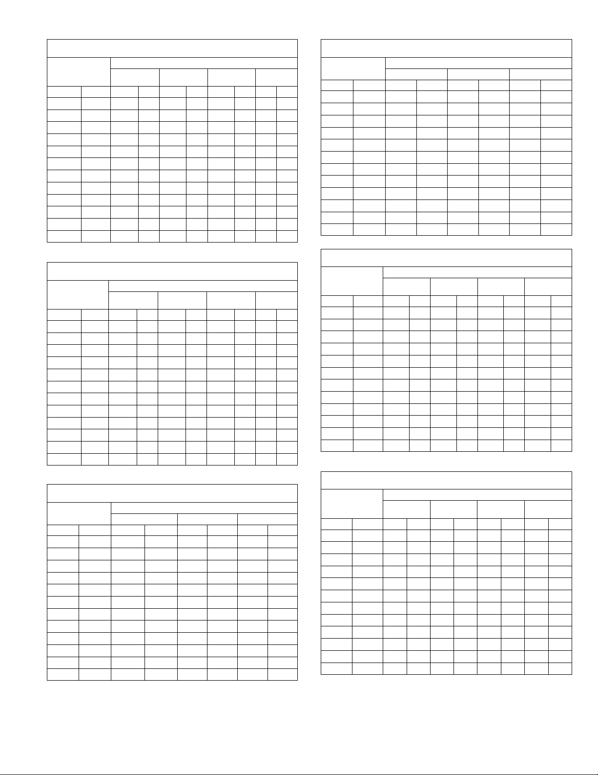
CHA16-036 BLOWER PERFORMANCE
@ 230 VOLTS (With Down-Flow Air Openings)
External Static
Pressure
in. w.g. Pa cfm L/s cfm L/s cfm L/s cfm L/s
0 0 1415 670 1350 635 1135 530 915 430
.05 12 1395 660 1335 630 1125 530 905 425
.10 25 1375 650 1315 620 111 5 525 895 420
.15 37 1360 640 1290 610 111 0 525 890 420
.20 50 1355 640 1275 600 1105 520 885 420
.25 62 1325 625 1255 590 1095 515 875 415
.30 75 1310 620 1235 585 1085 510 865 410
.40 100 1265 595 1195 565 1060 500 845 400
.50 125 1220 575 1155 545 1020 480 825 390
.60 150 1170 550 1105 520 975 460 785 370
.70 175 1115 525 1045 495 925 435 725 340
.75 185 1085 510 1010 475 895 420 685 325
NOTE Ċ For 208v unit operation, derate air volume by 7%. All air data is meaĆ
sured external to the unit with dry coil and without air filter.
CHA16-036 BLOWER PERFORMANCE
@ 230 VOLTS (With Horizontal Air Openings)
External Static
Pressure
in. w.g. Pa cfm L/s cfm L/s cfm L/s cfm L/s
0 0 1490 705 1460 690 1145 540 920 435
.05 12 1470 695 1440 680 1135 535 910 430
.10 25 1450 685 1420 670 1125 530 900 425
.15 37 1435 675 1395 660 1120 530 895 420
.20 50 1430 675 1375 650 1115 525 890 420
.25 62 1400 660 1355 640 1105 520 880 415
.30 75 1380 650 1335 630 1095 515 870 410
.40 100 1335 630 1285 605 1070 505 850 400
.50 125 1285 605 1235 585 1030 485 830 390
.60 150 1235 585 1195 565 985 465 790 375
.70 175 1185 560 1140 540 935 440 730 345
.75 185 1160 545 1110 525 905 425 690 325
NOTE Ċ All air data is measured external to the unit with dry coil and without air filter.
CHA16-036 BLOWER PERFORMANCE
@ 460/575 VOLTS (With Down-Flow Air Openings)
External Static
Pressure
in. w.g. Pa cfm L/s cfm L/s cfm L/s
0 0 1625 765 1465 690 1100 520
.05 12 1600 755 1445 680 1100 520
.10 25 1570 740 1420 670 1100 520
.15 37 1555 735 1395 660 1095 515
.20 50 1525 720 1385 655 1090 515
.25 62 1485 700 1365 645 1075 505
.30 75 1465 690 1340 630 1070 505
.40 100 1400 660 1285 605 1035 490
.50 125 1335 630 1235 585 1005 475
.60 150 1260 595 1165 550 955 450
.70 175 1170 550 1085 510 875 415
.75 185 1100 520 1045 495 815 385
NOTE Ċ All air data is measured external to the unit with dry coil and without air filter.
Air Volume at Various Blower Speeds
High
High
High Medium Low
MediumĆ
High
Air Volume at Various Blower Speeds
MediumĆ
High
Air Volume at Various Blower Speeds
MediumĆ
Low
MediumĆ
Low
Low
Low
CHA16-036 BLOWER PERFORMANCE
@ 460/575 VOLTS (With Horizontal Air Openings)
External Static
Pressure
in. w.g. Pa cfm L/s cfm L/s cfm L/s
Air Volume at Various Blower Speeds
High Medium Low
0 0 1710 805 1590 750 1105 520
.05 12 1685 795 1565 740 1105 520
.10 25 1655 780 1535 725 1105 520
.15 37 1630 770 1510 715 1100 520
.20 50 1610 760 1490 705 1095 515
.25 62 1570 740 1470 695 1085 510
.30 75 1540 725 1445 680 1075 505
.40 100 1475 695 1385 655 1040 490
.50 125 1405 665 1330 630 1010 475
.60 150 1335 630 1260 595 960 455
.70 175 1240 585 1185 560 885 420
.75 185 1180 555 1150 545 825 390
NOTE Ċ All air data is measured external to the unit with dry coil and without air filter.
CHA16-048 BLOWER PERFORMANCE
@ 230 VOLTS (With Down-Flow Air Openings)
External Static
Pressure
in. w.g. Pa cfm L/s cfm L/s cfm L/s cfm L/s
Air Volume at Various Blower Speeds
High
MediumĆ
High
MediumĆ
Low
Low
0 0 2065 975 1715 810 1515 715 1305 615
.05 12 2055 970 1705 805 1505 710 1300 615
.10 25 2040 965 1690 800 1495 705 1300 615
.15 37 2020 955 1680 795 1485 700 1295 610
.20 50 2000 945 1665 785 1475 695 1290 610
.25 62 1975 930 1650 780 1470 695 1285 605
.30 75 1950 920 1635 770 1450 685 1280 605
.40 100 1885 890 1600 755 1425 670 1260 595
.50 125 1810 855 1565 740 1395 660 1225 580
.60 150 1730 815 1525 720 1360 640 1175 555
.70 175 1645 775 1600 755 1320 625 111 0 525
.75 185 1600 755 1455 685 1295 610 1070 505
NOTE Ċ For 208v unit operation, derate air volume by 7%. All air data is meaĆ
sured external to the unit with dry coil and without air filter.
CHA16-048 BLOWER PERFORMANCE
@ 230 VOLTS (With Horizontal Air Openings)
External Static
Pressure
in. w.g. Pa cfm L/s cfm L/s cfm L/s cfm L/s
Air Volume at Various Blower Speeds
High
MediumĆ
High
MediumĆ
Low
Low
0 0 2140 1010 1785 840 1535 725 1305 615
.05 12 2115 1000 1770 835 1530 720 1300 615
.10 25 2090 985 1755 830 1520 715 1295 610
.15 37 2070 975 1745 825 1510 715 1290 610
.20 50 2045 965 1730 815 1500 710 1285 605
.25 62 2020 955 1715 810 1490 705 1280 605
.30 75 1995 940 1700 800 1480 700 1275 600
.40 100 1935 915 1665 785 1460 690 1260 595
.50 125 1875 885 1630 770 1430 675 1235 585
.60 150 1800 850 1585 750 1400 660 1205 570
.70 175 1710 805 1530 720 1370 645 1170 550
.75 185 1655 780 1495 705 1355 640 1150 545
NOTE Ċ For 208v unit operation, derate air volume by 7%. All air data is meaĆ
sured external to the unit with dry coil and without air filter.
Page 11
BLOWER DATA CHA16 Cont.
External Static
External Static
External Static
External Static
CHA16-048 BLOWER PERFORMANCE
@ 460/575 VOLTS (With Down-Flow Air Openings)
External Static
Pressure
in. w.g. Pa cfm L/s cfm L/s cfm L/s
0 0 2140 1010 1745 825 1175 555
.05 12 2120 1000 1730 815 1175 555
.10 25 2080 980 1720 810 1170 550
.15 37 2045 965 1710 805 1170 550
.20 50 2005 945 1695 800 1165 550
.25 62 1975 930 1680 795 1160 545
.30 75 1940 915 1665 785 1150 545
.40 100 1870 885 1625 765 1135 535
.50 125 1790 845 1580 745 111 0 525
.60 150 1705 805 1515 715 1075 505
.70 175 1605 760 1430 675 1030 485
.75 185 1555 740 1375 650 1000 470
NOTE Ċ All air data is measured external to the unit with dry coil and without air filter.
Air Volume at Various Blower Speeds
High Medium Low
CHA16-048 BLOWER PERFORMANCE
@ 460/575 VOLTS (With Horizontal Air Openings)
External Static
Pressure
in. w.g. Pa cfm L/s cfm L/s cfm L/s
Air Volume at Various Blower Speeds
High Medium Low
0 0 2160 1020 1815 855 1210 570
.05 12 2125 1005 1800 850 1210 570
.10 25 2095 990 1790 845 1200 565
.15 37 2060 970 1780 840 1200 565
.20 50 2025 955 1760 830 1195 565
.25 62 1990 940 1745 825 1190 560
.30 75 1955 925 1730 815 1185 560
.40 100 1885 890 1690 800 1170 550
.50 125 1805 850 1640 775 1140 540
.60 150 1715 810 1575 745 1105 520
.70 175 1615 760 1495 705 1065 505
.75 185 1560 735 1445 680 1040 490
NOTE Ċ All air data is measured external to the unit with dry coil and without air filter.
CHA16-060 BLOWER PERFORMANCE
@ 230 VOLTS (With DownĆFlow Air Openings)
External Static
Pressure
in. w.g. Pa cfm L/s cfm L/s cfm L/s cfm L/s cfm L/s
Air Volume at Various Blower Speeds
High
MediumĆ
High
Medium
MediumĆ
Low
Low
0 0 2725 1285 2490 1175 2235 1055 1940 915 1620 765
.05 12 2695 1270 2435 1150 2210 1045 1930 910 1625 765
.10 25 2665 1260 2430 1145 2185 1030 1925 910 1625 765
.15 37 2635 1245 2415 1140 2160 1020 1910 900 1610 760
.20 50 2600 1225 2395 1130 2140 1010 1895 895 1590 750
.25 62 2555 1205 2365 1115 2130 1005 1880 885 1580 745
.30 75 2510 1185 2335 1100 2115 1000 1865 880 1565 740
.40 100 2445 1155 2275 1075 2060 970 1830 865 1540 725
.50 125 2385 1125 2230 1050 2005 945 1765 835 1505 710
.60 150 2285 1080 2140 1010 1940 915 1725 815 1455 685
.70 175 2210 1045 2075 980 1880 885 1660 785 1405 665
.75 185 2175 1025 2030 960 1845 870 1615 760 1370 645
NOTE Ċ For 208v unit operation, derate air volume by 7%. All air data is meaĆ
sured external to the unit with dry coil and without air filter.
CHA16-060 BLOWER PERFORMANCE
@ 460/575 VOLTS (With Down-Flow Air Openings)
External Static
Pressure
in. w.g. Pa cfm L/s cfm L/s cfm L/s
Air Volume at Various Blower Speeds
High Medium Low
0 0 2725 1285 2405 1135 1905 900
.05 12 2680 1265 2365 1115 1890 890
.10 25 2635 1245 2325 1095 1870 880
.15 37 2590 1220 2290 1080 1855 875
.20 50 2550 1205 2255 1065 1840 870
.25 62 2515 1185 2220 1050 1820 860
.30 75 2485 1175 2190 1035 1795 845
.40 100 2395 1130 2120 1000 1745 825
.50 125 2325 1095 2050 965 1680 795
.60 150 2235 1055 1970 930 1570 740
.70 175 2150 1015 1900 895 1560 735
.75 185 2100 990 1860 880 1515 715
NOTE Ċ All air data is measured external to the unit with dry coil and without air filter.
CHA16-060 BLOWER PERFORMANCE
@ 230 VOLTS (With Horizontal Air Openings)
External Static
Pressure
in. w.g. Pa cfm L/s cfm L/s cfm L/s cfm L/s cfm L/s
Air Volume at Various Blower Speeds
High
MediumĆ
High
Medium
MediumĆ
Low
Low
0 0 2850 1345 2530 1195 2255 1065 1970 930 1640 775
.05 12 2820 1330 2475 1170 2230 1050 1965 925 1645 775
.10 25 2790 1315 2475 1170 2205 1040 1955 925 1645 775
.15 37 2760 1300 2455 1160 2180 1030 1940 915 1630 770
.20 50 2725 1285 2435 1150 2160 1020 1925 910 1610 760
.25 62 2680 1265 2405 1135 2150 1015 1910 900 1600 755
.30 75 2630 1240 2375 1120 2135 1010 1895 895 1585 750
.40 100 2570 1215 2315 1090 2080 980 1860 880 1560 735
.50 125 2510 1185 2270 1070 2025 955 1795 845 1525 720
.60 150 2410 1135 2180 1030 1960 925 1755 830 1475 695
.70 175 2335 1100 2115 1000 1900 895 1690 800 1425 670
.75 185 2300 1085 2070 975 1865 880 1650 780 1390 655
NOTE Ċ For 208v unit operation, derate air volume by 7%. All air data is meaĆ
sured external to the unit with dry coil and without air filter.
CHA16-060 BLOWER PERFORMANCE
@ 460/575 VOLTS (With Horizontal Air Openings)
External Static
Pressure
in. w.g. Pa cfm L/s cfm L/s cfm L/s
Air Volume at Various Blower Speeds
High Medium Low
0 0 2850 1345 2430 1145 1940 915
.05 12 2805 1325 2385 1125 1920 905
.10 25 2760 1300 2345 1105 1905 900
.15 37 2715 1280 2310 1090 1885 890
.20 50 2670 1260 2275 1075 1870 880
.25 62 2640 1245 2240 1055 1850 875
.30 75 2605 1230 2210 1045 1825 860
.40 100 2515 1185 2140 1010 1775 840
.50 125 2445 1155 2120 1000 1710 805
.60 150 2355 1110 1990 940 1600 755
.70 175 2270 1070 1920 905 1590 750
.75 185 2225 1050 1880 885 1545 730
NOTE - All air data is measured external to the unit with dry coil and without air filter.
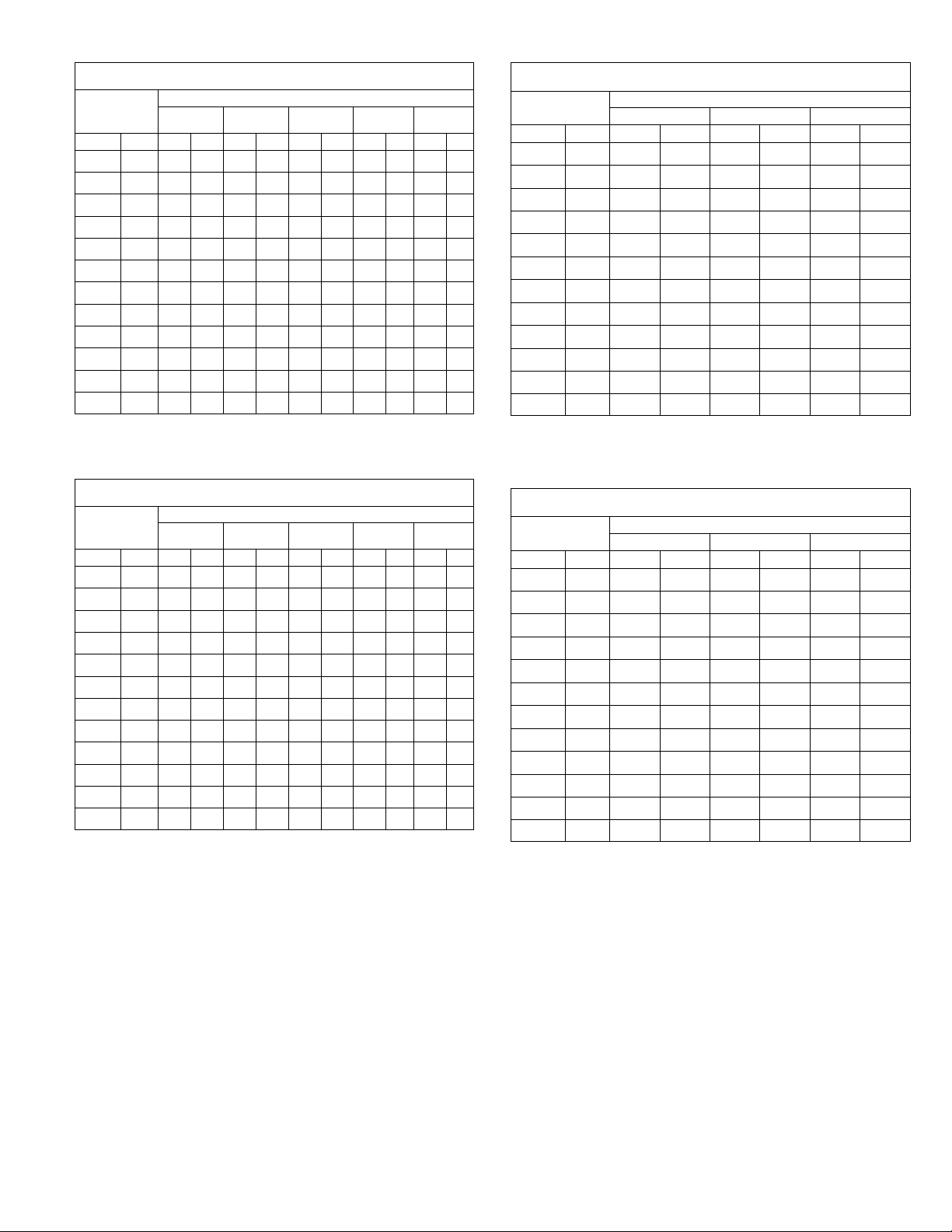
Page 12
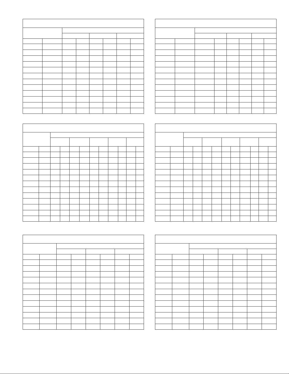
BLOWER DATA CHP16/20
CHP16/20Ć024 BLOWER PERFORMANCE
230 VOLTS (With DownĆFlow Air Openings)
External Static
Pressure
in. w.g. Pa cfm L/s cfm L/s cfm L/s cfm L/s
0 0 1385 655 1025 485 900 425 685 325
.05 12 1380 650 1035 490 915 430 700 330
.10 25 1365 645 1045 495 925 435 710 335
.15 37 1350 635 1045 495 930 440 715 335
.20 50 1330 630 1040 490 930 440 715 335
.25 62 1305 615 1030 485 925 435 715 335
.30 75 1275 600 1010 475 915 430 705 335
.40 100 1205 570 965 455 880 415 680 320
.50 125 1120 530 890 420 820 385 640 300
.60 150 1015 480 800 380 740 350 585 275
.70 175 900 425 685 325 640 300 510 240
.75 185 835 395 615 290 580 275 470 220
NOTE Ċ For 208v unit operation, derate air volume by 7% All air data is measured
external to the unit with dry coil and without air filter.
CHP16/20Ć024 BLOWER PERFORMANCE
230 VOLTS (With Horizontal Air Openings)
External Static
Pressure
in. w.g. Pa cfm L/s cfm L/s cfm L/s cfm L/s
0 0 1435 675 1035 490 895 420 625 295
.05 12 1420 670 1050 495 915 430 645 305
.10 25 1400 660 1060 500 925 435 660 310
.15 37 1380 650 1060 500 935 440 670 315
.20 50 1360 640 1060 500 935 440 675 320
.25 62 1335 630 1050 495 930 440 675 320
.30 75 1305 615 1035 490 920 435 670 315
.40 100 1235 585 985 465 875 415 650 305
.50 125 1155 545 910 430 810 380 605 285
.60 150 1065 505 810 380 720 340 545 255
.70 175 960 455 690 325 605 285 465 220
.75 185 905 425 620 295 540 255 415 195
NOTE Ċ For 208v unit operation, derate air volume by 7% All air data is measured
external to the unit with dry coil and without air filter.
Air Volume at Various Blower Speeds
High
High
MediumĆ
High
Air Volume at Various Blower Speeds
MediumĆ
High
MediumĆ
Low
MediumĆ
Low
Low
Low
CHP16/20Ć030 BLOWER PERFORMANCE
230 VOLTS (With Horizontal Air Openings)
External Static
Pressure
in. w.g. Pa cfm L/s cfm L/s cfm L/s cfm L/s
Air Volume at Various Blower Speeds
High
MediumĆ
High
MediumĆ
Low
Low
0 0 1485 700 1345 635 111 5 525 920 435
.05 12 1480 700 1340 630 1120 530 930 440
.10 25 1465 690 1335 630 1120 530 940 445
.15 37 1455 685 1325 625 111 5 525 945 445
.20 50 1435 675 1315 620 111 0 525 945 445
.25 62 1420 670 1305 615 1105 520 940 445
.30 75 1400 660 1285 605 1095 515 935 440
.40 100 1350 635 1250 590 1065 505 910 430
.50 125 1295 610 1200 565 1025 485 875 415
.60 150 1230 580 1145 540 975 460 820 385
.70 175 1160 545 1075 505 915 430 755 355
.75 185 1120 530 1040 490 885 420 720 340
NOTE Ċ For 208v unit operation, derate air volume by 7% All air data is measured
external to the unit with dry coil and without air filter.
CHP16/20Ć036 BLOWER PERFORMANCE
230 VOLTS (With DownĆFlow Air Openings)
External Static
Pressure
in. w.g. Pa cfm L/s cfm L/s cfm L/s cfm L/s
Air Volume at Various Blower Speeds
High
MediumĆ
High
MediumĆ
Low
Low
0 0 1360 640 1270 600 1070 505 890 420
.05 12 1355 640 1250 590 1060 500 885 420
.10 25 1350 635 1230 580 1050 495 880 415
.15 37 1330 630 1220 575 1035 490 870 410
.20 50 1310 620 1210 570 1020 480 860 405
.25 62 1295 610 1190 560 1005 475 845 340
.30 75 1280 605 1170 550 990 470 830 390
.40 100 1230 580 1130 535 960 455 800 380
.50 125 1170 550 1070 505 910 430 760 360
.60 150 1100 520 990 465 850 400 700 330
.70 175 1020 480 890 420 780 370 620 295
.75 185 975 460 830 390 740 350 570 270
NOTE Ċ For 208v unit operation, derate air volume by 7% All air data is measured
external to the unit with dry coil and without air filter.
CHP16/20Ć030 BLOWER PERFORMANCE
230 VOLTS (With DownĆFlow Air Openings)
External Static
Pressure
in. w.g. Pa cfm L/s cfm L/s cfm L/s cfm L/s
Air Volume at Various Blower Speeds
High
MediumĆ
High
MediumĆ
Low
Low
0 0 1485 700 1250 590 1085 500 905 425
.05 12 1460 690 1250 590 1075 505 900 425
.10 25 1430 675 1240 585 1070 505 895 420
.15 37 1400 660 1235 585 1060 500 890 420
.20 50 1375 650 1225 580 1045 495 885 420
.25 62 1345 635 1215 575 1035 490 875 415
.30 75 1315 620 1200 565 1020 480 865 410
.40 100 1255 590 1165 550 990 465 835 395
.50 125 1190 560 1125 530 950 450 805 380
.60 150 1125 530 1075 510 910 430 770 365
.70 175 1060 500 1015 480 865 410 725 340
.75 185 1025 485 985 465 840 395 700 330
NOTE Ċ For 208v unit operation, derate air volume by 7% All air data is measured
external to the unit with dry coil and without air filter.
Page 13
CHP16/20Ć036 BLOWER PERFORMANCE
230 VOLTS (With Horizontal Air Openings)
External Static
Pressure
in. w.g. Pa cfm L/s cfm L/s cfm L/s cfm L/s
Air Volume at Various Blower Speeds
High
MediumĆ
High
MediumĆ
Low
Low
0 0 1450 685 1370 645 1080 510 900 425
.05 12 1430 675 1350 635 1070 505 890 420
.10 25 1410 665 1330 630 1060 500 880 415
.15 37 1395 660 1310 615 1055 500 875 415
.20 50 1380 650 1290 610 1050 495 870 410
.25 62 1360 640 1270 600 1040 490 860 405
.30 75 1340 630 1250 590 1030 485 850 400
.40 100 1300 615 1210 570 1010 475 830 390
.50 125 1250 590 1170 550 970 460 810 380
.60 150 1200 565 1120 530 930 440 770 365
.70 175 1150 545 1060 500 890 420 710 335
.75 185 1125 530 1025 485 870 410 670 315
NOTE Ċ For 208v unit operation, derate air volume by 7% All air data is measured
external to the unit with dry coil and without air filter.
BLOWER DATA CHP16/20 Cont.
External Static
External Static
External Static
External Static
CHP16/20Ć036 BLOWER PERFORMANCE
460 VOLTS (With DownĆFlow Air Openings)
External Static
Pressure
in. w.g. Pa cfm L/s cfm L/s cfm L/s
0 0 1560 735 1380 650 1070 505
.05 12 1555 735 1355 640 1075 505
.10 25 1540 725 1330 630 1080 510
.15 37 1510 715 1320 625 1070 505
.20 50 1475 695 1315 620 1060 500
.25 62 1450 685 1295 610 1040 490
.30 75 1430 675 1270 600 1025 485
.40 100 1360 640 1215 575 980 460
.50 125 1280 605 1145 540 925 435
.60 150 1185 560 1045 495 850 400
.70 175 1070 505 925 435 750 355
.75 185 990 465 860 405 680 320
NOTE Ċ All air data is measured external to the unit with dry coil and without air filter.
CHP16/20Ć036 BLOWER PERFORMANCE
460 VOLTS (With Horizontal Air Openings)
External Static
Pressure
in. w.g. Pa cfm L/s cfm L/s cfm L/s
0 0 1665 785 1490 705 1080 510
.05 12 1640 775 1465 690 1080 510
.10 25 1610 760 1440 680 1080 510
.15 37 1585 750 1420 670 1075 505
.20 50 1555 735 1400 660 1070 505
.25 62 1525 720 1380 650 1060 500
.30 75 1495 705 1355 640 1050 495
.40 100 1435 675 1300 615 1015 480
.50 125 1365 645 1250 590 985 465
.60 150 1295 610 1180 555 935 440
.70 175 1205 570 1100 520 860 405
.75 185 1145 540 1060 500 800 380
NOTE Ċ All air data is measured external to the unit with dry coil and without air filter.
CHP20-042 CHP16/20Ć048 BLOWER PERFORMANCE
230 VOLTS (With Down-Flow Air Openings)
External Static
Pressure
in. w.g. Pa cfm L/s cfm L/s cfm L/s cfm L/s
0 0 2015 950 1610 760 1425 670 1240 585
.05 12 2000 945 1595 755 1420 670 1235 585
.10 25 1980 935 1580 745 1415 670 1235 585
.15 37 1960 925 1575 745 1415 670 1230 580
.20 50 1935 915 1560 735 1405 665 1225 580
.25 62 1910 900 1540 725 1395 660 1215 575
.30 75 1885 890 1520 715 1385 655 1205 570
.40 100 1825 860 1485 700 1355 640 1185 560
.50 125 1760 830 1445 680 1315 620 1160 550
.60 150 1690 800 1395 660 1260 595 1130 535
.70 175 1615 760 1335 630 1190 560 1095 515
.75 185 1575 745 1300 615 1145 540 1065 505
NOTE Ċ For 208v unit operation, derate air volume by 7% All air data is measured
external to the unit with dry coil and without air filter.
Air Volume at Various Blower Speeds
High Medium Low
Air Volume at Various Blower Speeds
High Medium Low
Air Volume at Various Blower Speeds
High
MediumĆ
High
MediumĆ
Low
Low
CHP20-042 CHP16/20Ć048 BLOWER PERFORMANCE
230 VOLTS (With Horizontal Air Openings)
External Static
Pressure
in. w.g. Pa cfm L/s cfm L/s cfm L/s cfm L/s
Air Volume at Various Blower Speeds
High
MediumĆ
High
MediumĆ
Low
Low
0 0 2075 980 1675 790 1445 680 1275 600
.05 12 2060 970 1660 785 1440 680 1270 600
.10 25 2040 965 1645 775 1435 675 1270 600
.15 37 2020 955 1635 770 1435 675 1265 595
.20 50 1995 940 1620 765 1425 670 1260 595
.25 62 1965 930 1600 755 1415 670 1250 590
.30 75 1940 915 1580 745 1405 665 1240 585
.40 100 1880 890 1545 730 1375 650 1220 575
.50 125 1815 855 1500 710 1335 630 1195 565
.60 150 1740 820 1450 685 1280 605 1165 550
.70 175 1655 780 1395 660 1210 570 1130 535
.75 185 1605 755 1365 645 1165 550 1110 525
NOTE Ċ For 208v unit operation, derate air volume by 7% All air data is measured
external to the unit with dry coil and without air filter.
CHP16/20Ć048 BLOWER PERFORMANCE
460 VOLTS (With DownĆFlow Air Openings)
External Static
Pressure
in. w.g. Pa cfm L/s cfm L/s cfm L/s
Air Volume at Various Blower Speeds
High Medium Low
0 0 2075 980 1650 780 1105 520
.05 12 2045 965 1635 770 1105 520
.10 25 2015 950 1625 765 1100 520
.15 37 1980 935 1615 760 1100 520
.20 50 1945 920 1600 755 1095 515
.25 62 1915 905 1585 750 1090 515
.30 75 1880 890 1570 740 1085 510
.40 100 1810 855 1535 725 1070 505
.50 125 1735 820 1490 705 1045 495
.60 150 1650 780 1430 675 1010 475
.70 175 1555 735 1355 640 965 455
.75 185 1500 710 1310 620 935 440
NOTE Ċ All air data is measured external to the unit with dry coil and without air filter.
CHP16/20Ć048 BLOWER PERFORMANCE
460 VOLTS (With Horizontal Air Openings)
External Static
Pressure
in. w.g. Pa cfm L/s cfm L/s cfm L/s
Air Volume at Various Blower Speeds
High Medium Low
0 0 2090 985 1755 830 111 5 525
.05 12 2065 975 1740 820 111 5 525
.10 25 2035 960 1720 810 111 0 525
.15 37 2005 945 1705 805 111 0 525
.20 50 1975 930 1685 795 1105 520
.25 62 1950 920 1675 790 1100 520
.30 75 1920 905 1650 780 1095 515
.40 100 1860 880 1600 755 1080 510
.50 125 1790 845 1555 735 1055 500
.60 150 1720 810 1495 705 1020 480
.70 175 1640 775 1425 670 975 460
.75 185 1595 755 1385 655 945 445
NOTE Ċ All air data is measured external to the unit with dry coil and without air filter.
Page 14
BLOWER DATA CHP16/20 Cont.
External
External Static
External Static
CHP16/20Ć060 BLOWER PERFORMANCE
230 VOLTS (With Down-Flow Air Openings)
External
Static
Pressure
in. w.g. Pa cfm L/s cfm L/s cfm L/s cfm L/s cfm L/s
0 0 2450 1155 2200 1040 1990 940 1760 830 1460 690
.05 12 2430 1145 2180 1030 1980 935 1750 825 1470 695
.10 25 2410 1135 2170 1025 1970 930 1740 820 1490 705
.15 37 2390 1130 2160 1020 1960 925 1730 815 1500 710
.20 50 2360 111 5 2140 1010 1950 920 1720 810 1490 705
.25 62 2340 1105 2120 1000 1930 910 1710 805 1490 705
.30 75 2320 1095 2100 990 1910 900 1700 800 1480 700
.40 100 2270 1070 2060 970 1880 885 1670 780 1470 695
.50 125 2230 1052 2010 950 1830 865 1640 775 1430 675
.60 150 2170 1025 1930 910 1780 840 1600 755 1390 655
.70 175 2120 1000 1890 890 1730 815 1550 730 1340 630
.75 185 2080 980 1850 875 1700 800 1530 720 1310 620
NOTE Ċ For 208v unit operation, derate air volume by 7% All air data is measured
external to the unit with dry coil and without air filter.
Air Volume at Various Blower Speeds
High
MediumĆ
High
Medium
MediumĆ
Low
Low
CHP16/20Ć060 BLOWER PERFORMANCE
460 VOLTS (With DownĆFlow Air Openings)
External Static
Pressure
in. w.g. Pa cfm L/s cfm L/s cfm L/s
Air Volume at Various Blower Speeds
High Medium Low
0 0 2450 1155 2090 985 1740 820
.05 12 2430 1145 2080 980 1740 820
.10 25 2410 1135 2060 970 1730 815
.15 37 2390 1130 2040 965 1720 810
.20 50 2360 1115 2020 955 1710 805
.25 62 2340 1105 2000 945 1700 800
.30 75 2320 1095 1990 940 1680 795
.40 100 2270 1070 1940 915 1630 770
.50 125 2230 1050 1880 885 1590 750
.60 150 2170 1025 1840 870 1520 715
.70 175 2120 1000 1770 835 1460 690
.75 185 2080 980 1740 820 1440 680
NOTE Ċ All air data is measured external to the unit with dry coil and without air filter.
CHP16/20Ć060 BLOWER PERFORMANCE
230 VOLTS (With Horizontal Air Openings)
External Static
Pressure
in. w.g. Pa cfm L/s cfm L/s cfm L/s cfm L/s cfm L/s
High
Air Volume at Various Blower Speeds
MediumĆ
High
Medium
MediumĆ
Low
Low
0 0 2570 1215 2220 1050 2000 945 1780 840 1510 715
.05 12 2560 1210 2210 1045 1990 940 1780 840 1520 715
.10 25 2540 1200 2200 1040 1980 935 1770 835 1530 720
.15 37 2520 1190 2190 1035 1970 930 1770 835 1520 715
.20 50 2500 1180 2180 1030 1960 925 1760 830 1510 715
.25 62 2480 1170 2160 1020 1940 915 1750 825 1510 715
.30 75 2440 1150 2140 1010 1920 905 1740 820 1500 710
.40 100 2390 1130 2100 990 1900 895 1710 805 1470 695
.50 125 2320 1095 2060 970 1860 880 1670 790 1440 680
.60 150 2240 1055 2010 950 1810 855 1630 770 1400 660
.70 175 2160 1020 1950 920 1760 830 1580 745 1350 635
.75 185 2120 1000 1920 905 1720 810 1560 735 1330 630
NOTE Ċ For 208v unit operation, derate air volume by 7% All air data is measured
external to the unit with dry coil and without air filter.
CHP16/20Ć060 BLOWER PERFORMANCE
460 VOLTS (With Horizontal Air Openings)
External Static
Pressure
in. w.g. Pa cfm L/s cfm L/s cfm L/s
Air Volume at Various Blower Speeds
High Medium Low
0 0 2570 1215 2100 990 1760 830
.05 12 2560 1210 2090 985 1770 835
.10 25 2540 1200 2070 975 1760 830
.15 37 2520 1190 2050 965 1760 830
.20 50 2500 1180 2030 960 1750 825
.25 62 2480 1170 2010 950 1740 820
.30 75 2440 1150 2000 945 1720 810
.40 100 2390 1130 1960 925 1670 790
.50 125 2320 1095 1910 900 1620 765
.60 150 2240 1105 1870 880 1550 730
.70 175 2160 1020 1800 850 1490 705
.75 185 2120 1000 1760 830 1470 695
NOTE Ċ All air data is measured external to the unit with dry coil and without air filter.
Page 15
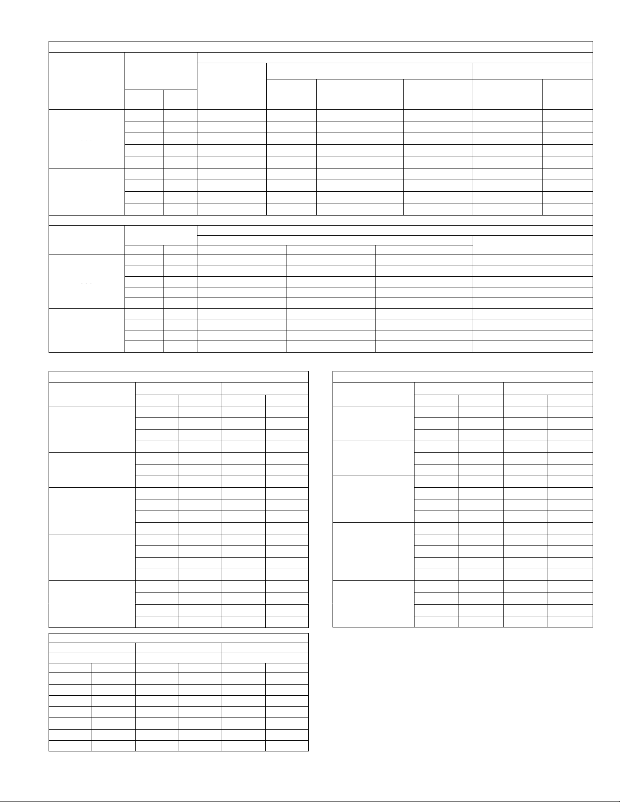
ACCESSORY BLOWER DATA CHA/CHP16/20
Unit
Volume
No
Filter
With Optional
With Optional
With
024
030
048
060
Unit
Air
Model
FD9Ć65
024
030
048
060
Model Numb
CHA16 030
Model Numb
CHP16/20 024
CHP16/20 030
CHP16/20-048
FILTER AND ACCESSORY AIR RESISTANCE CHA/CHP16/20
Unit
Model
No.
.
024
030
036
042
060
DIFFUSER AIR RESISTANCE CHA/CHP16/20
Model
No.
024
030
036
o42
060
Air
Volume
cfm L/s
1 in. (25mm)
Filter
Furnished
600 285 .13 (32) .05 (12) .21 (52) .09 (22) .12 (30) .07 (17)
800 380 .15 (37) .05 (12) .27 (67) .13 (32) .18 (45) .10 (25)
1000 470 .18 (45) .06 (15) .34 (85) .18 (45) .26 (65) .15 (37)
1200 565 .21 (52) .09 (22) .42 (104) .24 (60) .35 (87) .21 (52)
1400 660 .25 (62) .15 (37) .51 (127) .31 (77) .46 (114) .29 (72)
1600 755 .15 (37) .05 (12) .40 (99) .27 (67) .30 (75) .17 (42)
1800 850 .17 (42) .06 (15) .48 (119) .33 (82) .35 (87) .19 (47)
2000 945 .20 (50) .08 (20) .56 (139) .39 (97) .40 (99) .22 (55)
2200 1040 .23 (57) .10 (25) .66 (164) .46 (114) .47 (117) .26 (65)
Air
Volume
cfm L/s 2 Ends Open 1 Side 2 Ends Open All Ends & Sides Open
600 285 .12 (30) .11 (27) .08 (20) .08 (20)
800 380 .15 (37) .13 (32) .11 (27) .11 (27)
1000 470 .19 (47) .16 (40) .14 (35) .14 (35)
1200 565 .25 (62) .20 (50) .17 (42) .17 (42)
1400 660 .33 (82) .26 (65) .20 (50) .20 (50)
1600 755 .43 (107) .32 (80) .20 (50) .24 (60)
1800 850 .56 (139) .40 (90) .30 (75) .30 (75)
2000 945 .73 (182) .50 (124) .36 (90) .36 (90)
2200 1040 .95 (236) .63 (157) .44 (109) .44 (109)
Less
Filter
RTD9Ć65 Diffuser
Total Air Resistance Ċ inches water gauge (Pa)
REMD16 DownĆFlow Economizer
With Optional
Pleated
Polyester
2 in. (51mm) Filter
Total Air Resistance Ċ inches water gauge (Pa)
With Optional
Fiberglass
2 in. (51mm)
Filter
EMDH16 Horizontal
Economizer
With
Furnished
1 in. (25mm)
Filter
FD9Ć65
Diffuser
Less
Filter
WET INDOOR COIL AIR RESISTANCE CHA16
er
CHA16-024
CHA16-030
CHA16-036
CHA16-048
CHA16-060
CEILING DIFFUSER AIR THROW DATA CHA16 CHP16/20
Model No. RTD9-65 FD9-65
Air Volume
cfm L/s ft. m ft. m
1000 470
1200 565
1400 660
1600 755
1800 850
2000 945
2200 1040
Effective throw based on terminal velocities of 75 ft. (22.9 m) per minute.
Air Volume
cfm L/s in. w.g. Pa
600 285
800 380
1000 470
1200 565
800 380
1000 470
1200 565
800 380
1000 470
1200 565
1400 660
1600 755
1800 850
2000 945
2200 1040
1600 755
1800 850
2000 945
2200 1040
Effective Throw Effective Throw Ċ ft.
10-17 3-5 15-20 5-6
11-18 3-5 16-22 5-7
12-19 4-6 17-24 5-7
12-20 4-6 18-25 5-8
13-21 4-6 20-28 6-9
14-23 4-7 21-29 6-9
16-25 5-8 22-30 7-9
Air Resistance
0.05 12
0.06 15
0.07 17
0.08 20
0.09 22
0.10 25
0.11 27
0.09 22
0.10 25
0.11 27
0.12 30
0.11 27
0.12 30
0.13 32
0.14 35
0.08 20
0.09 22
0.10 25
0.11 27
(m)
WET INDOOR COIL AIR RESISTANCE CHP16/20
er
CHP16/20-024
CHP16/20-030
CHP16/20-036
CHP20--042
-
CHP16/20-060
Air Volume
cfm L/s in. w.g. Pa
600 285
800 380
1000 470
800 380
1000 470
1200 565
800 380
1000 470
1200 565
1400 660
1400 660
1600 755
1800 850
2000 945
2200 1040
1600 755
1800 850
2000 945
2200 1040
Air Resistance
0.05 12
0.06 15
0.07 17
0.09 22
0.10 25
0.11 27
0.07 17
0.08 20
0.09 22
0.10 25
0.12 30
0.13 32
0.14 35
0.15 37
0.16 40
0.11 27
0.12 30
0.13 32
0.14 35
Page 16
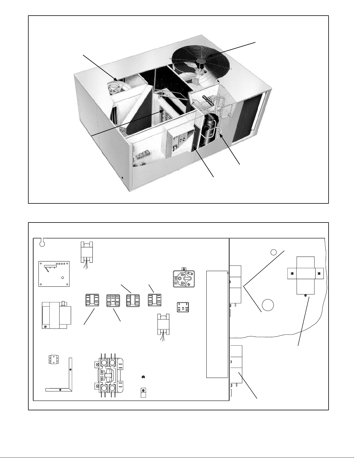
BLOWER ASSEMBLY
ELECTRICHEAT
ELEMENT
CHA/CHP16, CHP20 PARTS ARRANGEMENT
(shown with scroll compressor)
CONDENSER FAN
COMPRESSOR
CONTROL BOX
CMCI DEFROST
CONTROL
TRANSFORMER
T1
TERMINAL STRIP
TB32
TRANSFORMER T4
(024, 030, 036)
FAN RELAY
INBLOOR BLOWER
CONTACTOR K3
COMPRESSOR
CONTACTOR K1
FIGURE 1
CHA/CHP16, CHP20 CONTROL BOX
HARD START RELAY K31
CHA/CHP16-024/030
OUTDOOR
K10
DEFROST
RELAY
TRANSFER
REALY
K8
LATCH RELAY
K6
K4
TRANSFORMER T4
(042, 048, 060)
CAPACITOR C12
ALL P VOLT UNITS
CAPACITOR C1
CHP20-036, -060 G,J,M VOLTS
CHA/CHP16-036 G, J, M VOLTS
ALL Y VOLTAGE UNITS
CAPACITOR C1
CHP16/20-048-G. J, M, VOLTS
CHP16-060-G, J, M, VOLTS
FIGURE 2
Page 17
CAPACITOR C7
CHA/CHP16-024/030
I-APPLICATION
CHA/CHP16/20 2, 2 1/2 and 3 ton units are in the one cabiĆ
net size. CHA/CHP16/20 3.5, 4 and 5 ton units are also one
in one cabinet size. All CHA/CHP16/20 model units are apĆ
plicable for commercial, single or three phase installations.
CHA/CHP16/20 models are factory equipped with the hardĆ
ware required for installing Lennox' optional thermostat conĆ
trol systems like the T7300 or T8600 (refer to the EngineerĆ
ing Handbook for more specific application data).
II-UNIT COMPONENTS
CHA/CHP16/20 unit components are shown in figure 1.
A-Control Box Components
CHA/CHP16/20 control box is shown in figure 2. The control
box is located adjacent to the compressor compartment, beĆ
hind the control box access panel in front of the unit.
The condenser fan can be accessed by removing the fan
grill located on top of the unit.
The indoor blower access panel (all units) is located on the
opposite side of the unit from the heating compartment acĆ
cess.
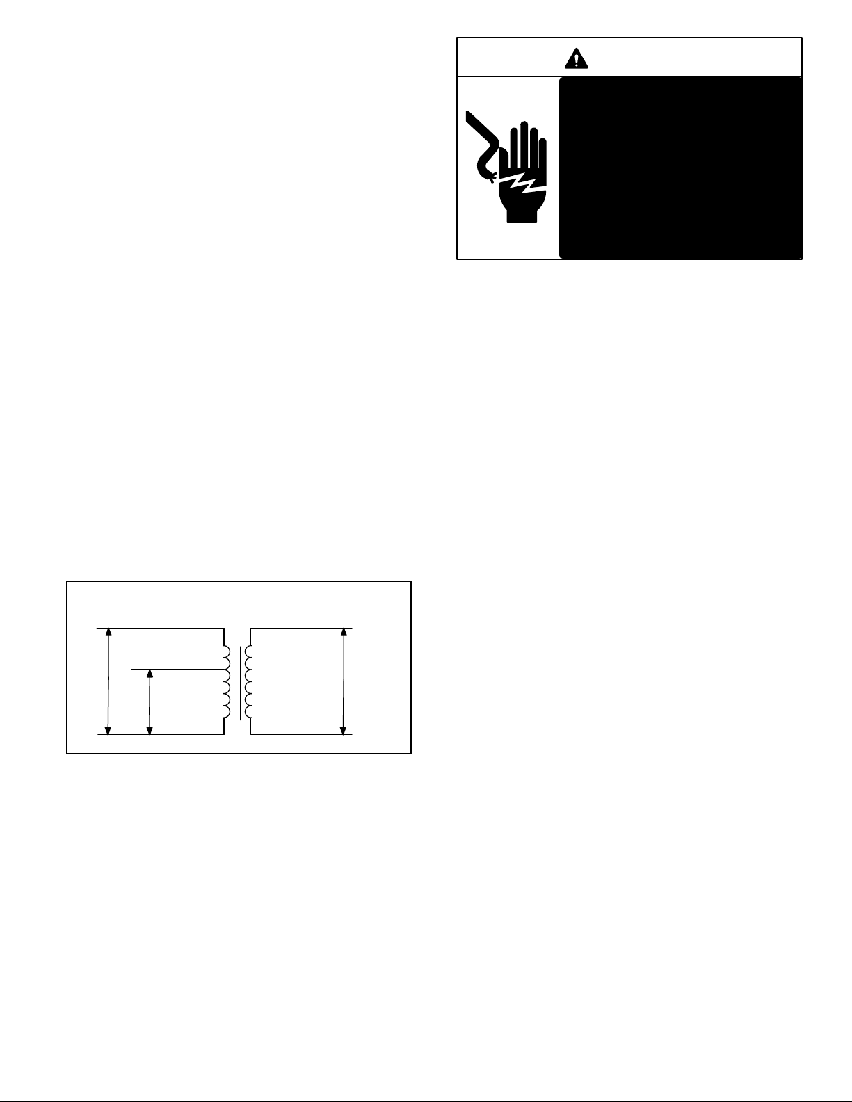
1-Transformer T1
All CHA/CHP16/20 series units use a single line voltage to
24VAC transformer mounted in the control box. The transĆ
former supplies power to control circuits in the unit. TransĆ
formers are rated at 70VA and use two primary voltage taps
as shown in figure 3. T1 is protected by a 3.5 amp circuit
breaker (CB8).
208 / 240 VOLT TRANSFORMER
PRIMARY SECONDARY
ORANGE
240 VOLTS
RED
208 VOLTS
BLUE
24 VOLTS
DANGER
Single -phase units use single
pole contactors. One leg of comĆ
pressor, capacitor and condensĆ
er fan are connected to line voltĆ
age at all times.
Remove all power to disconnect
before servicing.
Electrical shock resulting in
death or injury may result if
power is not disconnected.
NOTE-Contactor K1 is energized by the thermostat
control system. Depending on the control system
installed, the contactor may or may not be immediately
energized upon demand.
3-Indoor Blower Relay K3 (Cooling Speed)
208/230 volt units use a single DPDT relay to energize the
indoor blower motor. 460 volt and 575 volt units use a single
3PDT relay.
CHP16/20 units (singleĆphase and threeĆphase) use a
conventional 2 heat / 2 cool thermostat. Transfer relay
K8 is used to direct power to blower relay K3 depending on
whether the unit is in cooling or heating mode. In cooling
mode transfer relay K8 is deĆenergized and blower relay K3
is energized by thermostat terminal G through K8Ć1 normalĆ
ly closed contacts. In heating mode transfer relay K8 is enĆ
ergized and blower relay K3 is energized directly by transĆ
former T1 through K8Ć1 normally open contacts.
460 (G) voltage units use a unique blower motor which reĆ
quires the 3PDT relay. The motor utilizes the extra set of
N.C. relay contacts to complete an internal circuit when the
motor is on heating speed. Refer to the blower motor section
of this manual for more information.
BLACK
FIGURE 3
YELLOW
2-Cooling Contactor K1
K1 is a 24V to line voltage contactor used to energize the
compressor and condenser fan in response to thermostat
demand. Three-phase units use three-pole double-break
contactors. Single-phase units use single-pole contactors.
Page 18
4-Defrost Relay K4 (CHP Models Only)
Relay K4 initiates defrost in response to demand. K4 is enĆ
ergized when defrost thermostat S6 closes and defrost conĆ
trol CMC1 calls for defrost. Once energized, contacts K4Ć1
open to reset the internal timer to zero, contacts K4Ć2 close
to energize the electric heat (if installed) and K4Ć3 closes to
latch condenser fan relay K10 and defrost relay K4 through
defrost cycle.
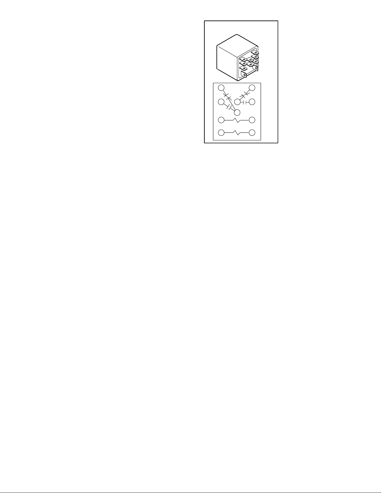
5-Start Capacitor C7
Compressor start capacitor C7 is used in CHA/
CHP16-024/030 units only, and located in the compressor
compartment. C7 is connected in parallel with capacitor
(C12). The capacitor is energized during compressor startĆ
up and is switched off by potential relay K31 when the comĆ
pressor nears full speed. See side of capacitor for ratings.
The start capacitor uses a 15K ohm 2 watt bleed" resistor
connected in parallel with the capacitor terminals. The resisĆ
tor is used to slowly discharge the capacitor when not in use.
6-Dual Capacitor C12
Single phase CHA/CHP16/20 model units use a single
dual" capacitor, connected to both the fan motor and the
compressor. A dual capacitor is two independent capacitors
inside one can. Each side of the capacitor has different ratĆ
ings and will be printed on the side.The capacitor is located
inside the compressor compartment.
7-Condenser Fan Relay K10
Condenser fan relay K10, used in all CHP16/20 units, is a
DPDT relay with a 24V coil. In all units K10 de-energizes conĆ
denser fan B4 in response to defrost demand.
8-Latch Relay K6
CHP16/20 commercial units are designed to use convenĆ
tional heat/cool thermostats and are equipped with latch
relay K6. Latch relay K6 is used in commercial heat pumps
to control operation of the reversing valves when a heat/cool
thermostat is used.
CHP16/20 series units are plumbed so that the unit is in coolĆ
ing mode when the reversing valve is energized. Latch relay
K6 controls operation of the reversing valves and is controlled
by the indoor thermostat.
A latch relay (figure 4) is a special type of relay with two coils;
a SET" coil and a RESET" coil. When 24VAC is applied to
the SET" coil, the normally open contacts close and the norĆ
mally closed contacts open. When power is removed from
the SET" coil, nothing happens; the N.O. contacts remain
closed and the N.C. contacts remain open. The contacts do
not return to their normal position until the RESET" coil is
energized. Once the contacts are reset, they remain in their
normal position when power is removed.
CHP16/20 series units use a
LATCH RELAY K6
DPDT latch relay. One set of
normally open contacts is conĆ
nected in series with thermostat
Y1 and compressor contactor
K1 while the matching normally
closed contacts are connected
in series with thermostat W1
and compressor contactor K1.
14
The other set of normally open
contacts is connected in series
568
10
9
RESET
13 14
12
SET
FIGURE 4
with the reversing valve. When
the SET" coil is energized (Y1),
the normally open contacts
close to energize the reversing
valve (thereby placing the unit in
cooling mode) and to energize
the compressor contactor.
When power is removed from the SET" coil (such as when
cooling demand is satisfied), the normally open contacts remain
closed, the reversing valve remains energized and the unit reĆ
mains in cooling mode.
9-Transfer Relay K8
The combined operation of latch relay K6 and transfer relay
K8 allow the CHP16 to use a conventional heat/cool thermoĆ
stat as opposed to a heat pump thermostat. Transfer relay
K8 switches thermostat blower demand from cooling mode
to heating mode. Relay K8 routes blower demand from the
appropriate thermostat output to the blower relay depending
on whether the unit is in cooling or heating mode.
During cooling mode, the blower relay receives power from
thermostat terminal G (relay K8 deĆenergized). During
heating demand transfer relay K8 is energized. When K8 is
energized, power routing is switched so that the blower
relay receives power from heating thermostat demand
(W1).
10-Potential Relay K31
Relay K31 is used in the CHA/CHP16-024/030 models ONLY
and is located in the control box. It is a potential relay which
controls the operation of the compressor starting circuit. The
relay is normally closed when the compressor (contactor K1)
is de-energized. Capacitor (C7) is connected to a set of norĆ
mally closed K31 contacts and assists the compressor in
starting. When K1 energizes, the compressor immediately beĆ
gins startĆup. K31 remains de-energized during compressor
start-up and the start capacitor (C7) remains in the circuit. As
the compressor gains speed K31 is energized by electromoĆ
tive forces generated by the compressor. When K31 enerĆ
gizes, its contacts open to take the start capacitor out of the
circuit.
Page 19
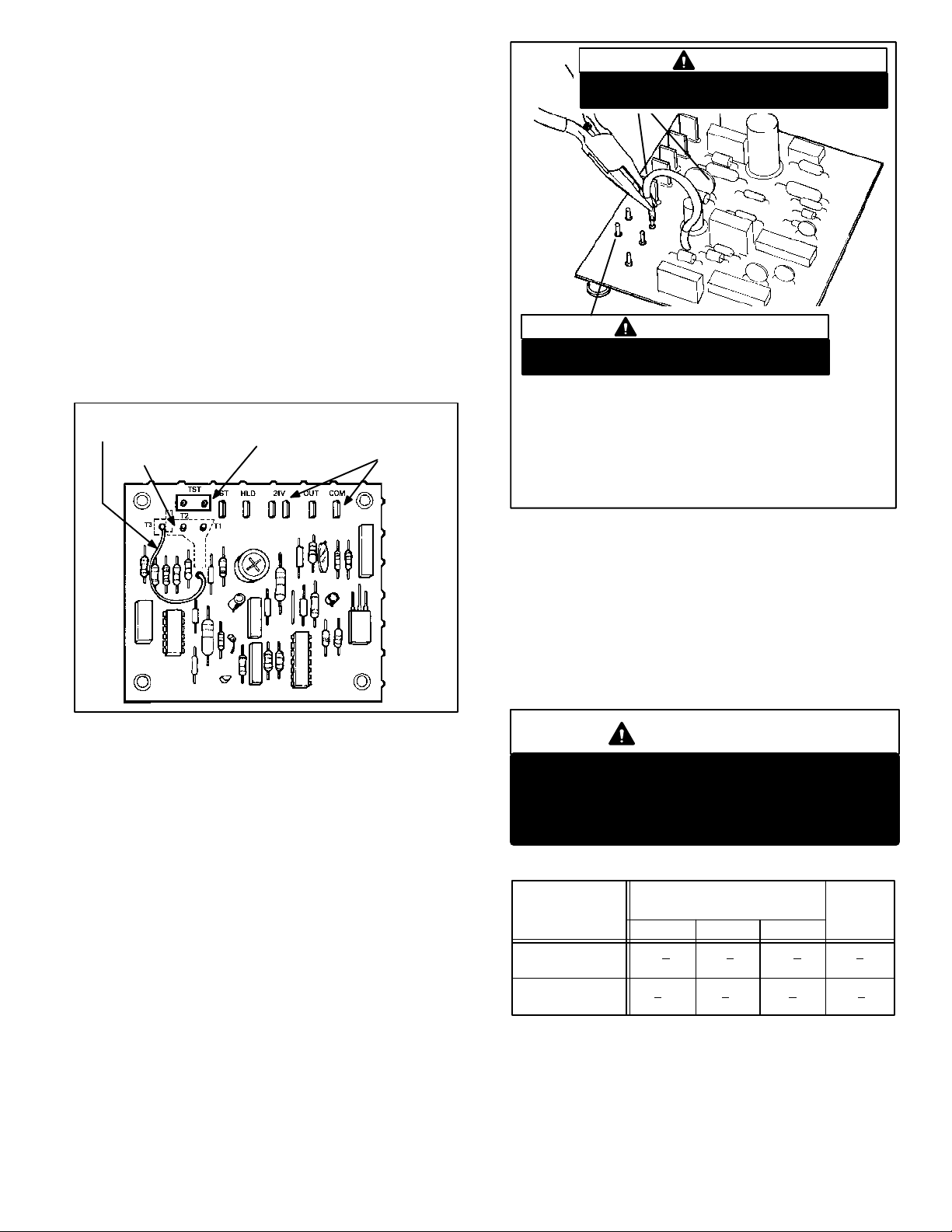
11-Defrost Control CMC1
GU
6
The CMC1 defrost control (figure 5 ) is a solid state control
which provides automatic switching from normal heating operaĆ
tion to defrost mode and back. The control provides maximum
14 minute defrost periods at 30, 60 or 90Ćminute fieldĆchangeĆ
able intervals. Each control monitors thermostat demand and
holds" the timer in place between thermostat demand. A set of
diagnostic pins are also provided for troubleshooting the refrigĆ
eration circuit.
The control contains a solid state timer which switches an exĆ
ternal defrost relay through 1/4" male spades mounted on the
control's circuit board. The control energizes the defrost relay
at regular timed intervals. Defrost thermostat S6 initiates deĆ
frost and pressure switch S46 terminates defrost. If S46 does
not terminate defrost, CMC1 will terminate defrost after 14
minutes.
SOLID STATE DEFROST TIMER
TIMING JUMPER
TIMING PINS
TROUBLESHOOTING
PINS
CONTROL
TERMINALS
IMPORTANT
Prevent control damage. Avoid contact with other
control terminals or control components.
NEEDLE-NOSE
PLIERS
IMPORTANT
Prevent control damage. Do not connect timing
jumper to either TST" pin.
TO CHANGE CONTROL TIMINGS:
1- Turn off all power to the unit to avoid damaging the circuit board.
2- Grasp wire connector firmly with needle nose pliers as shown.
3- Gently pull connector from pin.
4- Select new timing pin. DO NOT SELECT A TST" PIN.
5- Gently push connector onto desired pin (see Table 1 for timings).
Connector is seated when pin snaps.
6- Turn on power to unit.
FIGURE 5
When the indoor thermostat closes (call for heat or cool), deĆ
frost timer initiates 30, 60 or 90Ćminute (depending on how the
control is preset) timing sequence. At the end of the timing seĆ
quence, the control attempts to energize the defrost relay. If
both defrost thermostat and defrost pressure switch are
closed when timing sequence ends, the defrost relay is enerĆ
gized and defrost begins. Consequently, the defrost pressure
switch must open in order for defrost to be terminated (defrost
can also be terminated by the internal timer of the defrost conĆ
trol).
Defrost Control Components
a- Timing Pins 30(T1), 60(T2), 90(T3)
Each of these pins provides different timed interval beĆ
tween defrosts. A jumper connects the pins to circuit
board pin W1. Table 1 shows the timings of each pin.
The defrost interval can be field changed to 30, 60 or 90
minutes. The defrost period (14 minutes) cannot be
changed. To change the interval between defrosts, simĆ
ply remove the jumper from the pin it is connected to and
reconnect the jumper to one of the other available pins
(see figure 6).
FI
RE
b- Timing Jumper
A timing jumper is factory installed on the circuit board
and is used to connect pin W1 to one of three timing
pins. The jumper may be connected to any one timing
pin but must never be connected to the TST" pins. See
following Caution.
IMPORTANT
Potential for control damage.
Do not connect timing jumper to TST" pins.
TST" pins are used only during a test and must
not connect with timing pins.
TABLE 1
DEFROST
CONTROL CMC
TIMINGS
NORMAL
OPERATION
TST" PINS
JUMPERED
TOGETHER
c- 24V" Terminal
Terminal 24V" receives 24VAC from the control transĆ
former. This terminal powers the control's internal timer
and relays. Terminal 24V" must be powered at all times
in order to provide HOLD" between thermostat deĆ
mands.
INTERVAL BETWEEN
DEFROSTS WITH
JUMPER CONNECTED TO:
30 (T1) 60 (T2) 90 (T3)
30 + 3 60 + 6 90 + 9 14 + 1.4
MIN. MIN. MIN. MIN.
7 + 0.7 14 + 1.4 21 + 2.1 3.3 + 0.3
SEC. SEC. SEC. SEC.
DEFROST
TIME
Page 20
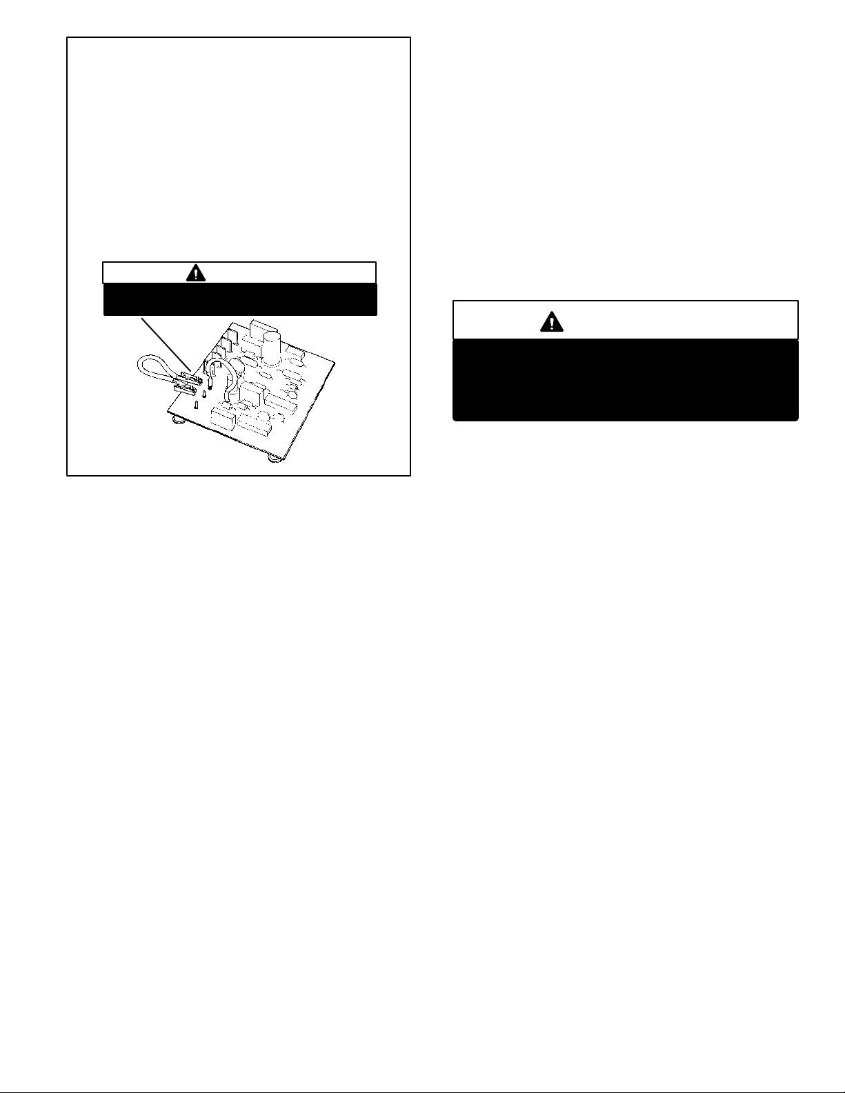
TO PLACE CONTROL IN TEST MODE:
1- Turn off all power to avoid damaging the circuit board.
2- Make sure all control terminals are connected as shown on unit
wiring diagram before attempting to place control in test mode.
See NOTE below.
NOTE - Control will not go into test mode when disconĆ
nected from unit. Unit load must be applied to control termiĆ
nals before the control will go into test mode.
3- Connect jumper to TST" pins as shown.
4- Turn indoor thermostat to heat mode and adjust to highest temperaĆ
ture setting.
5- Turn on power to unit.
6- See Table 1 for control timings in TST" mode.
7- Be sure to turn off power and remove jumper when test is complete.
Turn on power and re-adjust thermostat.
IMPORTANT
Prevent control damage. Avoid contact with other
control terminals or control components.
FIGURE 7
d- COM" Terminal
Terminal COM" provides 24VAC common.
e- HLD" Terminal
Terminal HLD" holds an internal timer in place between
thermostat demands and allows the unit to continue timĆ
ing upon resumption of thermostat demand. When therĆ
mostat demand is present, the control is allowed to count
down to the next defrost. Terminal HLD" is connected
directly to thermostat demand.
f- OUT" Terminal
Terminal OUT" controls defrost when connected to one
side of the defrost relay coil. An internal relay conĆ
nected to terminal OUT" closes (allowing an internal
path from OUT" to COM") to allow external defrost
relay to energize and initiate defrost. At the end of the
defrost period, the internal relay connected to terminal
OUT" opens to de-energize the external defrost relay.
g- RST" Terminal
Terminal RST" resets the internal timer when power is reĆ
moved and begins timer operation when power is returned.
Terminal RST" is connected to terminal COM" through a
set of normally closed defrost relay contacts. When the deĆ
frost relay contacts open terminal RST" loses power (the
path through RST" is disrupted) and internal timer is reset.
The control resumes timing when the defrost relay contacts
close.
h- TST" Pins
Each board is equipped with a set of test pins for use in
troubleshooting the unit. When jumpered together, these
pins reduce the control timing to a fraction of the original
time (see table 1 and figure 7).
IMPORTANT
Prevent control damage.
Control will begin test mode only if normal load
is applied to control terminals. Do not attempt
to operate or test control out of unit.
A defrost period can last up to 14 minutes and can be termiĆ
nated two ways. First, if the defrost pressure switch does not
open within 14 minutes after defrost begins, the internal timer
(by opening the internal path from OUT" to COM") will de-enĆ
ergize the defrost relay and the unit will resume normal operaĆ
tion. Second, if the defrost pressure switch opens during the
14 minute defrost period, the defrost relay is de-energized
and the unit resumes normal operation. Refer to figure 8.
Page 21
 Loading...