

Page 1
INSTALLATION AND SERVICE
PROCEDURE
Corp. 0906-L2
Service Literature
Revised August, 2018
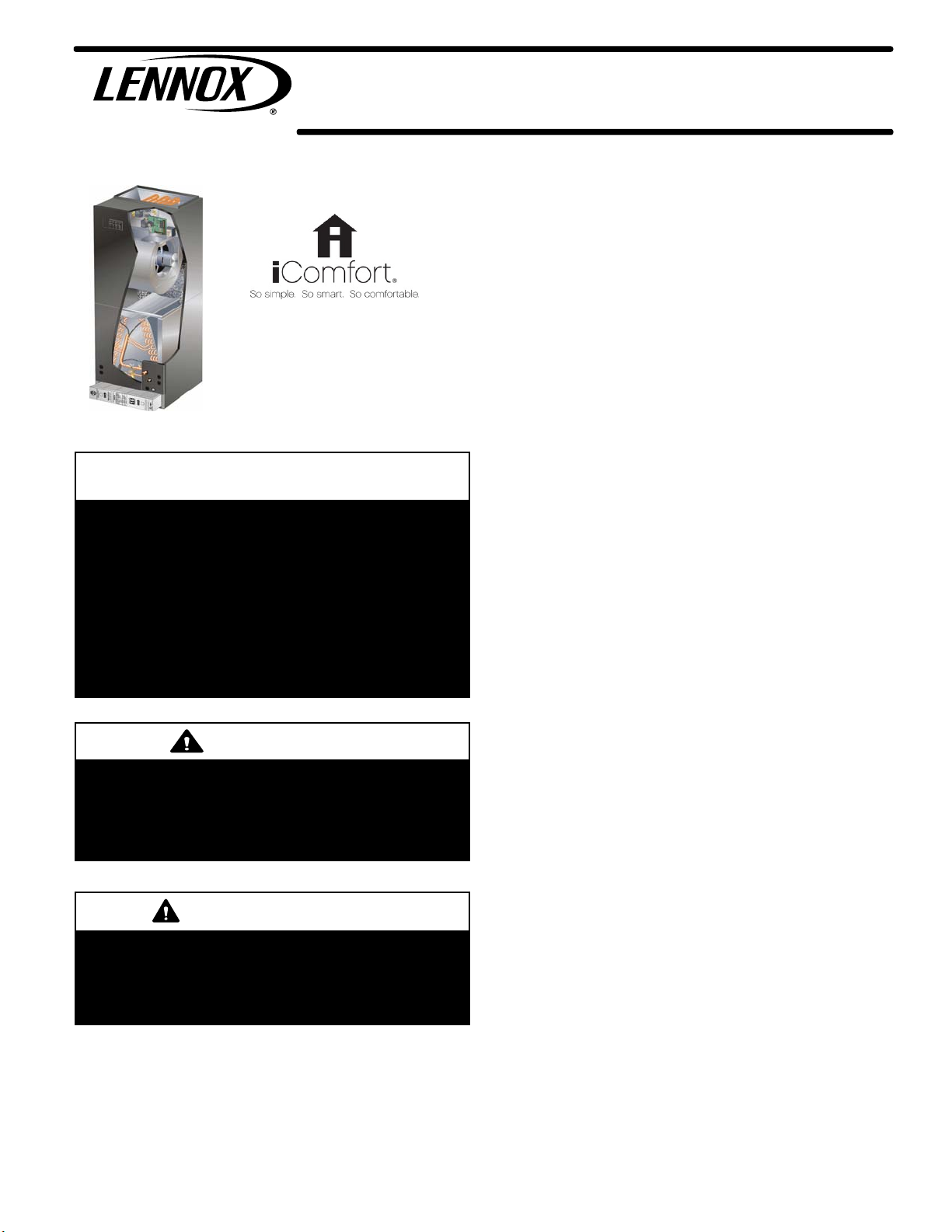
CBX40UHV (HFC-410A) SERIES UNITS (Communicating)
NOTICE
A thermostat is not included and must be ordered
separately.
D A Lennox communicating thermostat must be used in
communicating applications
(CBX40UHV-XXX-230-6-02 and later).
D In non-communicating applications, the Lennox
ComfortSense
as other non-communicating thermostats.
In all cases, setup is critical to ensure proper system
operation.
®
7500 thermostat may be used, as well
WARNING
Improper installation, adjustment, alteration, service or
maintenance can cause personal injury, loss of life, or
damage to property.
Installation and service must be performed by a licensed
professional installer (or equivalent) or a service agency.
CAUTION
Physical contact with metal edges and corners while
applying excessive force or rapid motion can result in
personal injury. Be aware of, and use caution when
working near these areas during installation or while
servicing this equipment.
CBX40UHV
TABLE OF CONTENTS
Model Number Identification 2.......................
Specifications / Electrical Data 2.....................
Blower Performance 3..............................
Parts Arrangement 3...............................
Application 9......................................
Unit Components 9.................................
Field Wiring 13....................................
Air Handler Control Button, Display and Jumpers 17....
Variable Speed ECM Blower Motor 20................
Optional ECB40 Electric Heat 25.....................
Optional Humidity Control 25........................
Unit Sequence of Operations 33.....................
Unit Status and Alarm Codes 35.....................
Application Configuration Modifications 38.............
Start-Up Operation 41..............................
Operating Characteristics 41........................
Maintenance 42....................................
Configuring Unit Flow Charts 43.....................
Unit Diagram 52...................................
Electric Heat Diagrams and Sequence of
Operations 53.....................................
CBX40UHV series units are designed to be matched with
Lennox two‐stage or single‐stage HFC-410A air conditioner
units and heat pumps. Several models are available in sizes
ranging from 2 through 5 tons. All units are equipped with
factory installed HFC-410A check and expansion valve for
cooling or heat pump applications.
This air handler is compatible with the ComfortSense® 7500
non-communicating thermostat and non-communicating
outdoor units. In addition, this unit has the enhanced
capability of communicating with a communicating
thermostat and compatible outdoor units using the Lennox
RSBus protocols.
Optional ECB40 electric heat is available in several kW
sizes, and can be field installed in the cabinets.
This document provides service information on the
following model builds:
1. Non-communicating version (CBX40UHV-XXX-
230-6-01)
2. Communicating version (CBX40UHV-XXX-
230-6-02) or later.
Page 1
2018 Lennox Industries Inc.
Page 2
MODEL NUMBER IDENTIFICATION
CB X 40 UHV − 036 − 230 − 6 − 02
Unit Type
Minor Revision Number
CB = Air Handler
Refrigerant Type
X = R-410A
Series
Configuration
UHV = Up-Flow/Horizontal, Variable
Speed Blower Motor
Nominal Cooling Capacity
Refrigerant Metering Device
2 = Fixed Orifice
3 = TXV - Bleedport (indoor unit)
4 = TXV - Non-bleedport (indoor unit)
5 = TXV - Non-bleedport (outdoor unit)
6 = TXV - R-410A Non-bleedport (indoor unit)
Voltage
230 = 208/230V-60hz-1ph
024 = 2 tons
030 = 2.5 tons
036 = 3 tons
042 = 3.5 tons
048 = 4 tons
060 = 5 tons
SPECIFICATIONS / ELECTRICAL DATA
Refer to the Unit Engineering Handbook or Lennox Price Book for optional accessories for this unit.
SPECIFICATIONS
General Data
Model Number
Nominal cooling capacity - tons
Refrigerant
Connections
in.
Indoor
Coil
Blower Data Wheel nominal diameter x width - in.
Filters (MERV16)
Shipping Data - 1 Package - lbs.
Suction (vapor) line - sweat
Liquid line - sweat
Condensate drain (fpt)
Net face area - ft.
Tube outside diameter - in.
Number of rows
Fins per inch
Motor output - hp
1
Size - in.
CBX40UH
V
‐024
2 2.5 3 3.5 4 5
HFC-410A HFC-410A HFC-410A HFC-410A HFC-410A HFC-410A
3/4 3/4 3/4 7/8 7/8 7/8
3/8 3/8 3/8 3/8 3/8 3/8
(2) 3/4 (2) 3/4 (2) 3/4 (2) 3/4 (2) 3/4 (2) 3/4
2
5.0 5.0 5.0 7.22 7.22 7.22
3/8 3/8 3/8 3/8 3/8 3/8
3 3 3 3 3 3
12 12 12 12 12 12
11 X 8 11 X 8 11 X 8 11-1/2 X 9 11-1/2 X 9 11-1/2 X 9
1/2 1/2 3/4 1 1 1
20 X 20 X 5 20 X 20 X 5 20 X 20 X 5 20 X 25 X 5 20 X 25 X 5 20 X 25 X 5
165 167 172 214 216 216
CBX40UH
V
‐030
CBX40UH
V
‐036
CBX40UH
V
‐042
ELECTRICAL DATA
Voltage - phase - 60hz
2
Maximum overcurrent protection (unit only)
Minimum circuit ampacity (unit only)
1
Disposable frame type filter.
2
HACR type circuit breaker or fuse.
15 15 15 20 20 20
5 5 10 10 10 10
208/230V-1PH
CBX40UH
V
‐048
CBX40UH
V
‐060
Page 2
CBX40UHV
Page 3
BLOWER DATA
CBX40UHV024 BLOWER PERFORMANCE
0 through 0.80 in. W.g. External Static Pressure Range
“AJUST”
Jumper Setting
1
“HEAT” Speed “COOL” Speed
2
Jumper Speed Positions
3
4
1
2
3
4
NOTES:
+
NORM
-
cfm
715 855 1000 1130 465 690 900 1050
670 770 900 1035 425 620 825 950
580 700 800 930 385 560 735 850
cfm
cfm
cfm
cfm
cfm
cfm
cfm
S The effect of static pressure, filter and electric heater resistance is included in the air volumes listed.
S First stage cooling air volume is 70% of COOL speed settings. Continuous fan speed is approximately 28%, 38%, 70% and 100% (Jumper
selectable) of the same secondstage COOL speed selected, minimum 250 cfm.
S Lennox Harmony III™ Zone Control applications - minimum blower speed if 250 cfm.
CBX40UHV‐024 BLOWER MOTOR WATTS AT “+” (Plus) AHC SETTING (Adjust Jumper at “+” Setting)
AHC Jumper Speed
Positions
TAP 1 53 68 89 113 143 163 191 214 232
HEAT SPEED
COOL SPEED
CBX40UHV‐024 BLOWER MOTOR WATTS AT “NORM” AHC SETTING (Adjust Jumper at NORM Setting)
TAP 2 73 93 122 141 170 200 234 260 282
TAP 3 105 141 168 179 217 248 275 306 348
TAP 4 132 159 189 218 248 285 313 349 393
TAP 1 25 35 56 73 89 98 114 130 143
TAP 2 45 64 79 101 130 151 180 211 216
TAP 3 75 103 127 146 177 210 243 266 298
TAP 4 11 4 142 175 200 219 258 280 332 363
0 0.1 0.2 0.3 0.4 0.5 0.6 0.7 0.8
AHC Jumper Speed
Positions
HEAT SPEED
COOL SPEED
TAP 1 48 64 79 103 128 156 182 196 207
TAP 2 61 80 98 123 149 175 206 233 254
TAP 3 77 101 128 151 178 214 239 267 300
TAP 4 109 142 171 193 223 245 286 325 359
TAP 1 23 38 52 68 80 91 111 128 135
TAP 2 34 53 76 94 111 142 152 176 203
TAP 3 64 87 11 3 130 158 190 226 247 270
TAP 4 89 120 145 166 198 225 258 289 319
0 0.1 0.2 0.3 0.4 0.5 0.6 0.7 0.8
Motor Watts @ Various External Static Pressures - in. wg.
Motor Watts @ Various External Static Pressures - in. wg.
CBX40UHV‐024 BLOWER MOTOR WATTS AT “-” (Minus) AHC SETTING (Adjust Jumper at “-” Setting)
AHC Jumper Speed
Positions
HEAT SPEED
COOL SPEED
CBX40UHV
0 0.1 0.2 0.3 0.4 0.5 0.6 0.7 0.8
TAP 1 38 56 70 94 11 3 130 154 176 192
TAP 2 53 68 88 110 138 163 195 207 234
TAP 3 62 84 103 125 155 186 213 246 268
TAP 4 89 116 141 165 192 220 250 278 314
TAP 1 22 33 47 61 71 83 98 11 0 123
TAP 2 30 46 63 86 102 11 8 138 162 172
TAP 3 54 71 91 116 138 171 191 221 247
TAP 4 66 86 11 7 138 159 195 227 253 286
Motor Watts @ Various External Static Pressures - in. wg.
Page 3
Page 4

CBX40UHV030 BLOWER PERFORMANCE
0 through 0.80 in. W.g. External Static Pressure Range
“AJUST”
Jumper Setting
1
“HEAT” Speed “COOL” Speed
2
Jumper Speed Positions
3
4
1
2
3
4
NOTES:
+
NORM
-
cfm
800 935 1070 1210 660 880 1100 1320
725 850 975 1100 600 800 1000 1200
655 765 880 990 540 720 900 1080
cfm
cfm
cfm
cfm
cfm
cfm
cfm
S The effect of static pressure, filter and electric heater resistance is included in the air volumes listed.
S First stage cooling air volume is 70% of COOL speed settings. Continuous fan speed is approximately 28%, 38%, 70% and 100% (Jumper
selectable) of the same secondstage COOL speed selected, minimum 250 cfm.
S Lennox Harmony III™ Zone Control applications - minimum blower speed if 250 cfm.
CBX40UHV‐030 BLOWER MOTOR WATTS AT “+” (Plus) AHC SETTING (Adjust Jumper at “+” Setting)
AHC Jumper Speed
Positions
TAP 1 66 87 11 4 134 162 185 214 239 268
HEAT SPEED
COOL SPEED
CBX40UHV‐030 BLOWER MOTOR WATTS AT “NORM” AHC SETTING (Adjust Jumper at NORM Setting)
TAP 2 101 124 151 175 192 224 243 273 325
TAP 3 134 171 188 212 243 273 296 329 366
TAP 4 182 211 245 285 319 353 375 405 444
TAP 1 47 63 82 101 121 151 175 193 206
TAP 2 83 107 131 152 178 202 231 265 296
TAP 3 142 170 196 220 251 282 315 345 367
TAP 4 209 258 295 345 373 418 452 482 512
0 0.1 0.2 0.3 0.4 0.5 0.6 0.7 0.8
AHC Jumper Speed
Positions
HEAT SPEED
COOL SPEED
TAP 1 57 77 94 115 146 172 195 219 232
TAP 2 79 104 123 149 168 196 231 264 294
TAP 3 111 139 164 186 209 233 261 298 334
TAP 4 148 178 199 231 260 293 314 355 382
TAP 1 38 53 68 94 11 3 127 149 169 185
TAP 2 67 84 105 131 152 178 207 240 257
TAP 3 110 141 164 188 213 240 266 292 330
TAP 4 168 197 226 260 302 338 366 400 434
0 0.1 0.2 0.3 0.4 0.5 0.6 0.7 0.8
Motor Watts @ Various External Static Pressures - in. wg.
Motor Watts @ Various External Static Pressures - in. wg.
CBX40UHV‐030 BLOWER MOTOR WATTS AT “-” (Minus) AHC SETTING (Adjust Jumper at “-” Setting)
AHC Jumper Speed
Positions
HEAT SPEED
COOL SPEED
TAP 1 48 66 83 107 127 149 171 199 217
TAP 2 63 80 103 125 145 178 200 229 246
TAP 3 86 113 135 155 179 203 244 270 305
TAP 4 109 144 165 191 212 240 264 296 338
TAP 1 32 47 60 86 101 11 3 134 151 168
TAP 2 54 70 88 107 132 157 188 210 225
TAP 3 87 114 137 159 183 206 232 267 302
TAP 4 130 165 184 207 245 270 300 326 363
0 0.1 0.2 0.3 0.4 0.5 0.6 0.7 0.8
Motor Watts @ Various External Static Pressures - in. wg.
Page 4
CBX40UHV
Page 5
CBX40UHV036 BLOWER PERFORMANCE
0 through 0.80 in. W.g. External Static Pressure Range
“AJUST”
Jumper Setting
1
“HEAT” Speed “COOL” Speed
2
Jumper Speed Positions
3
4
1
2
3
4
NOTES:
+
NORM
-
cf
1230 1335 1445 1545 900 1225 1380 1545
m
1120 1215 1315 1400 810 1125 1275 1400
1010 1185 1200 1265 730 1000 1135 1265
cf
m
cfm
cfm
cf
m
cf
m
cfm
cfm
S The effect of static pressure, filter and electric heater resistance is included in the air volumes listed.
S First stage cooling air volume is 70% of COOL speed settings. Continuous fan speed is approximately 28%, 38%, 70% and 100% (Jumper
selectable) of the same secondstage COOL speed selected, minimum 380 cfm.
S Lennox Harmony III™ Zone Control applications - minimum blower speed if 380 cfm.
CBX40UHV‐036 BLOWER MOTOR WATTS AT “+” (Plus) AHC SETTING (Adjust Jumper at “+” Setting)
AHC Jumper Speed
Positions
HEAT SPEED
COOL SPEED
CBX40UHV‐036 BLOWER MOTOR WATTS AT “NORM” AHC SETTING (“Adjust” Jumper at NORM Setting)
TAP 1 189 223 253 271 306 323 359 377 409
TAP 2 238 273 295 316 349 375 417 439 473
TAP 3 279 322 348 384 420 463 486 525 550
TAP 4 327 387 427 451 489 537 566 600 643
TAP 1 130 157 184 212 237 263 284 307 346
TAP 2 183 211 232 261 296 314 342 368 396
TAP 3 248 284 315 349 366 407 441 473 509
TAP 4 347 376 418 464 495 531 566 608 632
0 0.1 0.2 0.3 0.4 0.5 0.6 0.7 0.8
AHC Jumper Speed
Positions
HEAT SPEED
COOL SPEED
TAP 1 146 173 199 225 257 279 304 330 364
TAP 2 186 234 241 264 296 319 340 371 395
TAP 3 226 263 281 304 341 371 393 435 456
TAP 4 261 296 321 355 389 423 450 489 519
TAP 1 98 117 143 165 185 216 247 267 301
TAP 2 144 168 197 223 250 272 299 332 356
TAP 3 198 227 265 279 307 340 363 397 431
TAP 4 255 285 313 346 386 418 454 483 527
0 0.1 0.2 0.3 0.4 0.5 0.6 0.7 0.8
Motor Watts @ Various External Static Pressures - in. wg.
Motor Watts @ Various External Static Pressures - in. wg.
CBX40UHV‐036 BLOWER MOTOR WATTS AT “-” (Minus) AHC SETTING (“Adjust” Jumper at “-” Setting)
AHC Jumper Speed
Positions
HEAT SPEED
COOL SPEED
CBX40UHV
0 0.1 0.2 0.3 0.4 0.5 0.6 0.7 0.8
TAP 1 11 0 139 161 185 213 234 263 291 312
TAP 2 182 210 236 252 293 315 336 356 393
TAP 3 175 193 224 257 294 312 330 350 382
TAP 4 199 234 257 291 309 333 366 395 423
TAP 1 86 102 124 143 165 193 218 246 270
TAP 2 103 130 148 172 192 219 248 277 309
TAP 3 144 163 192 216 250 275 294 322 357
TAP 4 196 224 255 287 306 339 371 395 429
Motor Watts @ Various External Static Pressures - in. wg.
Page 5
Page 6

CBX40UHV042 BLOWER PERFORMANCE
0 through 0.80 in. W.g. External Static Pressure Range
“AJUST”
Jumper Setting
1
“HEAT” Speed “COOL” Speed
2
Jumper Speed Positions
3
4
1
2
3
4
NOTES:
+
NORM
-
cfm
1100 1320 1540 1760 1100 1320 1540 1760
1000 1200 1400 1600 1000 1200 1400 1600
900 1080 1260 1440 900 1080 1260 1440
cfm
cfm
cfm
cfm
cfm
cfm
cfm
S The effect of static pressure, filter and electric heater resistance is included in the air volumes listed.
S First stage cooling air volume is 70% of COOL speed settings. Continuous fan speed is approximately 28%, 38%, 70% and 100% (Jumper
selectable) of the same secondstage COOL speed selected, minimum 450 cfm.
S Lennox Harmony III™ Zone Control applications - minimum blower speed if 450 cfm.
CBX40UHV‐042 BLOWER MOTOR WATTS AT “+” (Plus) AHC SETTING (“Adjust” Jumper at “+” Setting)
AHC Jumper Speed
Positions
HEAT SPEED
COOL SPEED
CBX40UHV‐042 BLOWER MOTOR WATTS AT “NORM” AHC SETTING (“Adjust” Jumper at NORM Setting)
TAP 1 124 154 177 204 240 260 296 326 363
TAP 2 179 227 255 287 336 356 394 451 486
TAP 3 294 339 387 425 463 489 518 550 600
TAP 4 405 456 510 553 607 647 686 743 777
TAP 1 122 146 173 198 224 259 292 329 360
TAP 2 186 230 254 289 332 361 404 438 477
TAP 3 284 335 387 413 455 483 526 551 600
TAP 4 413 475 517 570 632 569 715 750 782
0 0.1 0.2 0.3 0.4 0.5 0.6 0.7 0.8
AHC Jumper Speed
Positions
“HEAT” SPEED
COOL SPEED
TAP 1 97 123 146 179 205 225 258 292 327
TAP 2 144 180 209 230 266 295 334 375 410
TAP 3 226 259 307 342 380 405 448 482 525
TAP 4 323 369 401 449 491 516 563 593 640
TAP 1 93 118 142 166 197 225 247 280 314
TAP 2 148 179 207 231 268 311 333 377 405
TAP 3 229 263 298 332 386 408 446 484 534
TAP 4 327 375 403 448 489 523 557 589 646
0 0.1 0.2 0.3 0.4 0.5 0.6 0.7 0.8
Motor Watts @ Various External Static Pressures - in. wg.
Motor Watts @ Various External Static Pressures - in. wg.
CBX40UHV‐042 BLOWER MOTOR WATTS AT “-” (Minus) AHC SETTING (“Adjust” Jumper at “-” Setting)
AHC Jumper Speed
Positions
HEAT SPEED
COOL SPEED
TAP 1 80 105 128 148 173 206 233 265 287
TAP 2 113 144 172 193 219 265 286 312 349
TAP 3 168 198 238 265 293 332 368 415 442
TAP 4 239 285 315 362 398 428 465 503 544
TAP 1 76 100 123 148 169 203 230 260 279
TAP 2 115 145 169 190 217 258 288 315 349
TAP 3 166 199 236 263 296 330 380 415 449
TAP 4 241 289 321 366 396 431 472 505 544
0 0.1 0.2 0.3 0.4 0.5 0.6 0.7 0.8
Motor Watts @ Various External Static Pressures - in. wg.
Page 6
CBX40UHV
Page 7
CBX40UHV048 AND CBX40UHV-060 BLOWER PERFORMANCE
0 through 0.80 in. W.g. External Static Pressure Range
Jumper Speed Positions
“AJUST”
Jumper Setting
1
“HEAT” Speed “COOL” Speed
2
3
4
1
2
3
4
NOTES:
+
NORM
-
cfm
1850 1960 2090 2150 1625 1820 2055 2145
1705 1800 1900 2005 1425 1625 1805 2005
1560 1625 1720 1770 1205 1375 1555 1725
cfm
cfm
cfm
cfm
cfm
cfm
cfm
S The effect of static pressure, filter and electric heater resistance is included in the air volumes listed.
S First stage cooling air volume is 70% of COOL speed settings. Continuous fan speed is approximately 28%, 38%, 70% and 100% (Jumper
selectable) of the same secondstage COOL speed selected, minimum 450 cfm.
S Lennox Harmony III™ Zone Control applications - minimum blower speed if 450 cfm.
CBX40UHV‐048 and CBX40UHV-060 BLOWER MOTOR WATTS AT “+” (Plus) AHC SETTING (“Adjust” Jumper at “+”
Setting)
AHC Jumper Speed
Positions
HEAT SPEED
COOL SPEED
TAP 1 418 478 539 551 599 646 675 704 748
TAP 2 492 540 585 642 684 732 761 797 834
TAP 3 594 645 721 762 811 863 874 918 976
TAP 4 653 713 755 809 861 909 941 974 1028
TAP 1 312 342 373 414 443 475 512 558 587
TAP 2 407 459 503 552 591 627 670 718 752
TAP 3 581 646 691 737 792 826 863 900 942
TAP 4 646 695 746 804 873 900 934 976 1032
0 0.1 0.2 0.3 0.4 0.5 0.6 0.7 0.8
Motor Watts @ Various External Static Pressures - in. wg.
CBX40UHV‐048 and CBX40UHV-060 BLOWER MOTOR WATTS AT “NORM” AHC SETTING (“Adjust” Jumper at NORM
Setting)
AHC Jumper Speed
Positions
HEAT SPEED
COOL SPEED
TAP 1 325 366 404 444 475 520 566 598 636
TAP 2 369 421 465 516 560 587 616 666 717
TAP 3 436 488 540 586 621 671 710 743 789
TAP 4 523 581 636 684 738 789 816 852 894
TAP 1 226 259 293 322 350 387 413 446 472
TAP 2 312 355 382 423 450 492 520 570 615
TAP 3 388 421 482 523 564 606 641 695 741
TAP 4 538 599 647 686 718 792 820 853 888
0 0.1 0.2 0.3 0.4 0.5 0.6 0.7 0.8
Motor Watts @ Various External Static Pressures - in. wg.
CBX40UHV
Page 7
Page 8
CBX40UHV‐048 and CBX40UHV-060 BLOWER MOTOR WATTS AT “-” (Minus) AHC SETTING (“Adjust” Jumper at “-”
Setting)
AHC Jumper Speed
Positions
HEAT SPEED
COOL SPEED
TAP 1 271 302 341 368 398 439 473 504 545
TAP 2 286 329 356 393 423 462 504 550 572
TAP 3 327 374 407 455 504 526 563 608 638
TAP 4 355 404 442 496 539 560 602 643 684
TAP 1 124 163 180 209 231 271 300 322 357
TAP 2 192 233 252 282 321 356 390 422 449
TAP 3 268 311 336 367 393 432 469 523 538
TAP 4 328 376 420 463 486 536 572 612 657
0 0.1 0.2 0.3 0.4 0.5 0.6 0.7 0.8
Motor Watts @ Various External Static Pressures - in. wg.
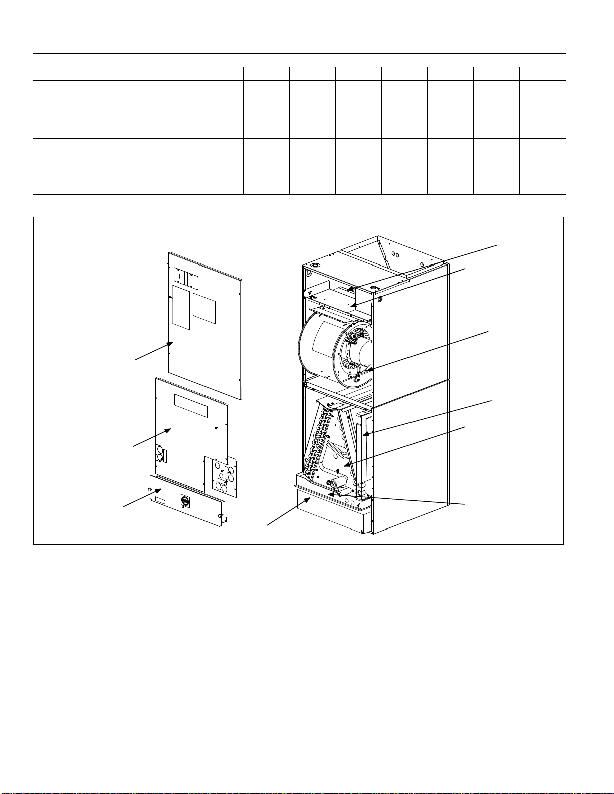
PARTS ARRANGEMENT
ELECTRIC HEAT
SECTION
CONTROL BOX
BLOWER
COMPARTMENT
BLOWER ACCESS
PANEL
COIL ACCESS
PANEL
FILTER ACCESS
PANEL
HORIZONTAL
DRAIN PAN
COIL
UP-FLOW/DOWN-FLOW
DRAIN PAN
FILTER
Figure 1. CBX40UHV Parts Arrangement
Page 8
CBX40UHV
Page 9
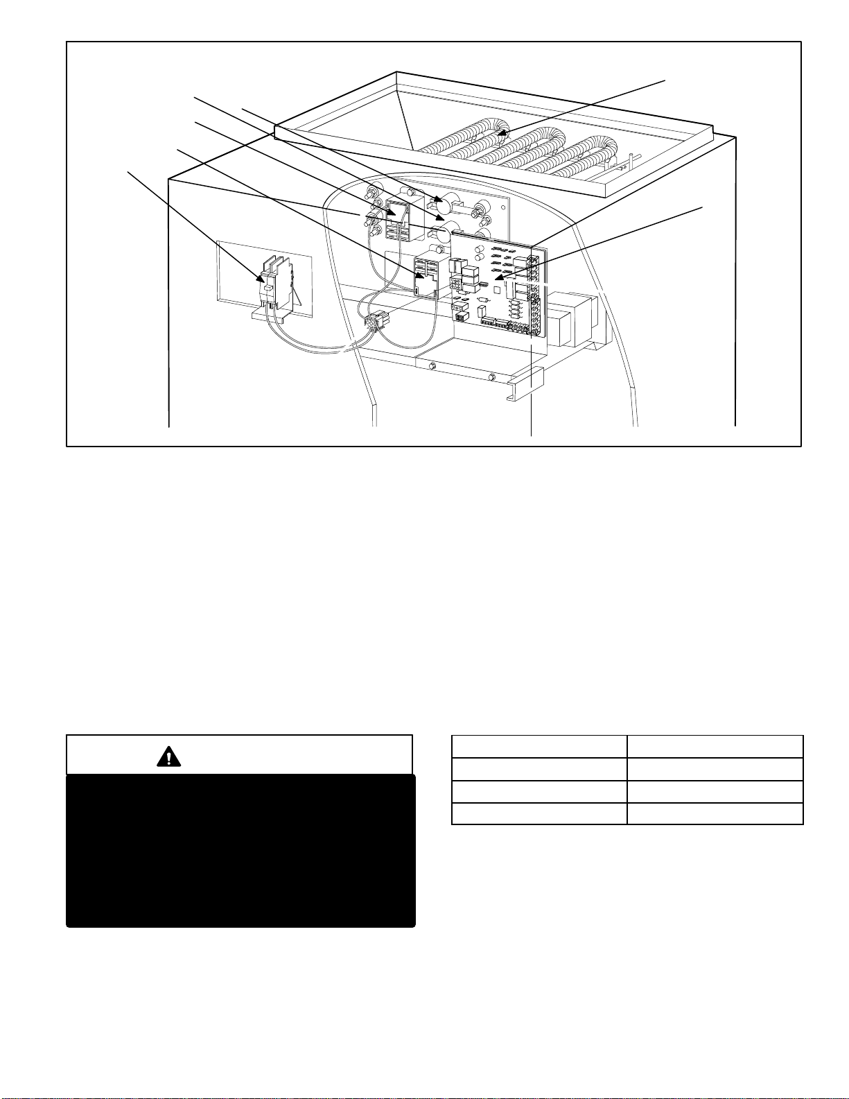
LIMIT
RELAY
RELAY
CIRCUIT BREAKER
LIMIT
Figure 2. CBX40UHV Control Box
APPLICATION
CBX40UHV air handlers are designed for HFC-410A
applications only. All major air handler components
must be matched according to Lennox
reco m mendation s for the u n i t to be covered under
warranty. Refer to the Engineering Handbook for approved
system matchups. A misapplied system will cause erratic
operation and can result in early unit failure. The units come
with factory installed check and expansion valve for all
applications. It has been installed internally and is accessible if
required.
ELECTROSTATIC DISCHARGE (ESD)
PRECAUTIONS AND PROCEDURES
CAUTION
Electrostatic discharge can affect electronic compo
nents. Take precautions during unit installation and
service to protect the unit's electronic controls. Pre
cautions will help to avoid control exposure to electro
static discharge by putting the unit, the control and the
technician at the same electrostatic potential.
Neutralize electrostatic charge by touching hand and
all tools on an unpainted unit surface before perform
ing any service procedure.
HEATING ELEMENTSHEATING ELEMENTS
AIR HANDLER CONTROL
UNIT COMPONENTS
Control Box
The CBX40UHV control box is shown in figure 2. Line
voltage and electric heat connections are made in the
control box. Optional electric heat fits through an opening
located in the center of the control box. When electric heat
is not used, knockout plates cover the opening. The electric
heat control arrangement is detailed in the electric heat section
of this manual.
Low voltage connections are made on the air handler
control (AHC) also located in the control box. All AHC will
have factory installed clippable links connecting DS to R, R
to O and Y1 to Y2. These links will have to be removed in
certain unit application. See table 1.
Table 1. Links
Application
Remove Links
Harmony IIIt DS to R
Heat Pump R to O
Two-Stage Cooling Y1 to Y2
Transformer (T1)
All CBX40UHV series units use a single line voltage to
24VAC transformer mounted in the control box. The
transformer supplies power to the control circuits in the
indoor and outdoor unit. Transformers are rated at 70VA.
208/240VAC single‐phase transformers use two primary
voltage taps.
CBX40UHV
Page 9
Page 10
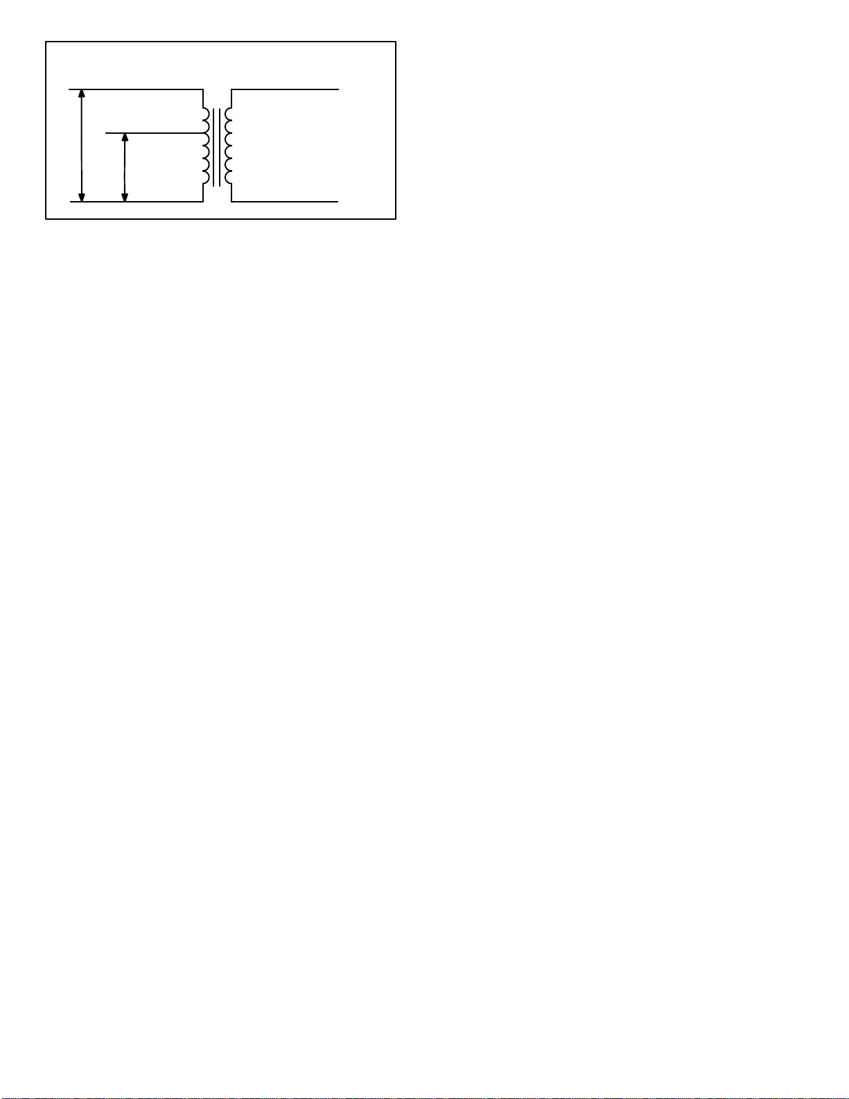
208 / 240 VOLT TRANSFORMER
PRIMARY
ORANGE
240 VOLTS
RED
SECONDARY
BLUE
Air Handler Control (AHC)
The Air Handler Control manages electric heat, indoor
blower and accessory controls. The Air Handler Control
also provides system configuration and air-flow
adjustments plus diagnostic capabilities.
208 VOLTS
BLACK
YELLOW
Figure 3 Transformer
Plastic Drain Pans
Both up-flow/down-flow and horizontal drain pans are
provided and installed on the CBX40UHV units. The drain
pans are made from fiberglass‐filled plastic. The drain hole
is used for right‐hand air discharge only, and must be
plugged when the unit is configured for left‐hand air
discharge. Each pan has a set of connections, one for a
primary drain and one for an auxiliary drain.
Coil
All CBX40UHV series units have dual slab coils arranged in
an ”A” configuration. Each coil has two or three rows of
copper tubes fitted with ripple‐edge aluminum fins. A check
and expansion valve complete with inlet screen feeds
multiple parallel circuits through the coils. The coil is
designed to easily slide out of the unit cabinet.
Discharge Sensor (DAT)
The Air Handler Control has two screw terminals marked
Discharge Air Sensor. The sensor is REQUIRED for
®
EvenHeater
operation and is field mounted and ordered
separately, use Lennox Catalog # 88K38.
In the EvenHeater mode, the discharge air sensor cycles
the electric heating elements as needed to maintain the Air
Handler control EvenHeater jumper selected discharge
setpoint.
The discharge air sensor should be mounted downstream
of the electric heat elements as illustrated in Figure 4, Detail
A. It must be placed in a location with unobstructed airflow,
where other accessories (such as humidifiers, UV lights,
etc.) will not interfere with its accuracy.
Wiring distance between the Air Handler Control and the
discharge air sensor should not exceed 10' (3m) when
wired with 18-gauge thermostat wire.
Outdoor Air Sensor (OAS)
These terminals are for FUTURE USE. (DO NOT USE).
Page 10
CBX40UHV
Page 11
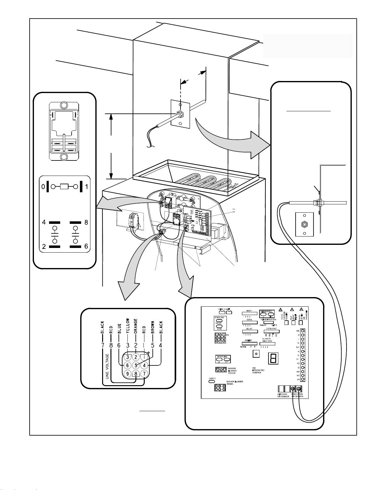
ELECTRIC HEAT RELAY
PART NO. 49W91
19 IN.
(483 MM)
5-1/2 IN.
(140 MM)
SENSOR
(CENTER SIDE-T0 -SIDE)
DETAIL A
THE AIR HANDLER CONTROL (AHC) HAS TWO
SCREW TERMINALS MARKED DISCHARGE AIR
SENSOR. THE SENSOR IS REQUIRED FOR
EVENHEATER
MOUNTED AND MUST BE ORDERED
SEPARATELY (CATALOG # 88K38).
®
OPERATION, IS FIELD
OPTIONAL DISCHARGE
SENSOR (DAT)
TEMPERATURE RESISTANCE
CHART
TEMP RESISTANCE
ºF (OHMS)
30 34,566
40 26,106
50 19,904
60 15,313
70 11,884
80 9,298
90 7,332
100 5,826
22V DIRECT CURRENT COIL
30 AMP CONTACT
RATING
DETAIL B
SEE TABLE 6 - STAGES
FOR FUNCTION OF
EACH PIN POSITION.
CONNECTOR
9-PIN CONNECTOR
9-PIN
FASTEN THE PROBE
BRACKET TO THE
PLENUM WITH TWO
SELF-TAPPING SHEET
METAL SCREWS.
AIR HANDLER
CONTROL
SECURING
SCREWS
AIR HANDLER CONTROL
L-BRACKET MOUNTING PLATE
CBX40UHV AIR HANDLER CONTROL
PART NO. 43W19
PLENUM
NOTE - EVENHEATER MODE CANNOT BE ENABLED WITH HARMONY III
DUE TO EACH CONTROL REQUIRING ITS OWN DISCHARGE AIR SENSOR.
Figure 4. CBX40UHV-XXX-230-6-01
CBX40UHV
T
Page 11
CONNECT WIRES TO DISCHARGE AIR SENSOR
TERMINAL ON AIR HANDLER CONTROL.
Page 12
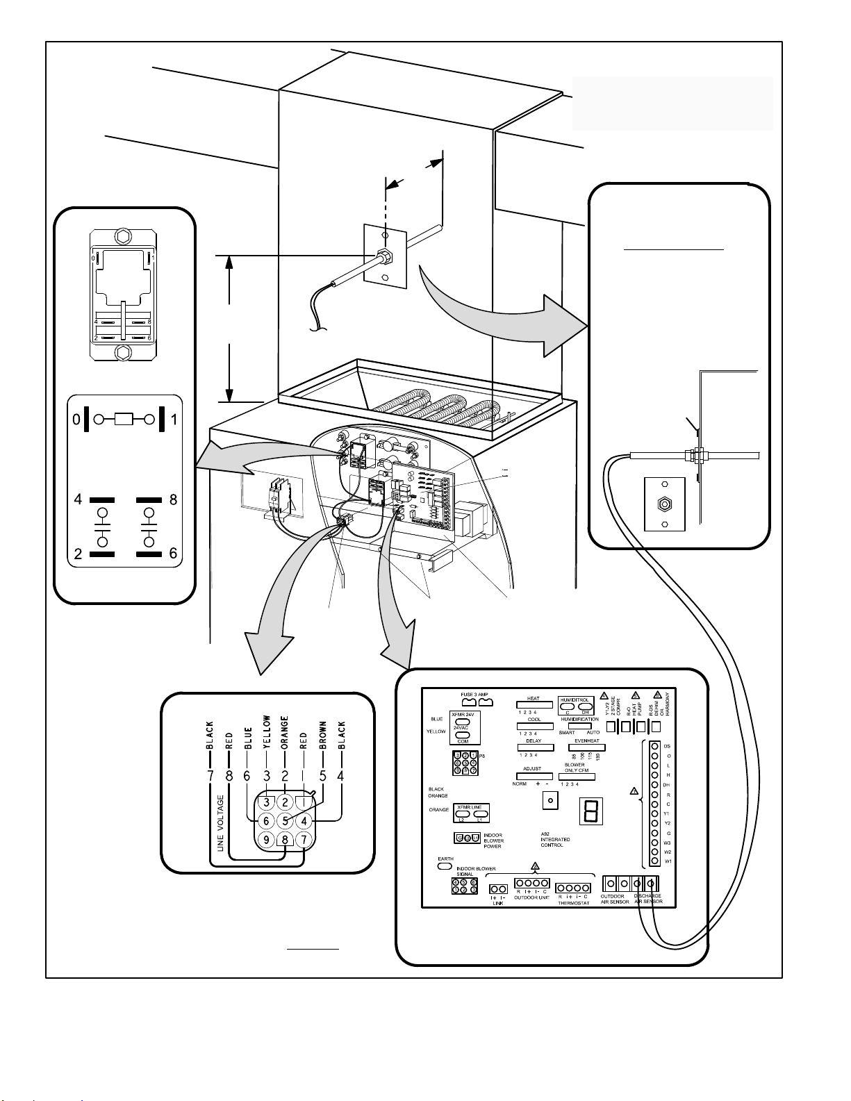
DETAIL A
THE AIR HANDLER CONTROL (AHC) HAS TWO
SCREW TERMINALS MARKED DISCHARGE AIR
SENSOR. THE SENSOR IS REQUIRED FOR
EVENHEAT OPERATION, IS FIELD-MOUNTED
AND MUST BE ORDERED SEPARATELY
(CATALOG # 88K38).
ELECTRIC HEAT RELAY
PART NO. 49W91
22V DIRECT CURRENT COIL
19 IN.
(483 MM)
5-1/2 IN.
(140 MM)
SENSOR
(CENTER SIDE-T0 -SIDE)
AIR HANDLER
CONTROL
DISCHARGE SENSOR
(DAT)
TEMPERATURE RESISTANCE
CHART
TEMP RESISTANCE
ºF (OHMS)
30 34,566
40 26,106
50 19,904
60 15,313
70 11,884
80 9,298
90 7,332
100 5,826
FASTEN THE PROBE
BRACKET TO THE
PLENUM WITH TWO
SELF-TAPPING SHEET
METAL SCREWS.
PLENUM
30 AMP CONTACT
RATING
9-PIN
CONNECTOR
9-PIN CONNECTOR
DETAIL B
SEE TABLE 6 - STAGES
FOR FUNCTION OF
EACH PIN POSITION.
NOTE — EVENHEAT MODE CANNOT BE ENABLED WITH HARMONY III DUE
TO EACH CONTROL REQUIRING ITS OWN DISCHARGE AIR SENSOR.
SECURING
SCREWS
AIR HANDLER CONTROL
L-BRACKET MOUNTING PLATE
CBX40UHV AIR HANDLER CONTROL
PART NO. 50W28 or 65W70
CONNECT WIRES TO DISCHARGE AIR SENSOR
TERMINAL ON AIR HANDLER CONTROL.
Figure 5. Component Connections (CBX40UHV-XXX-230-6-02)
Page 12
CBX40UHV
Page 13
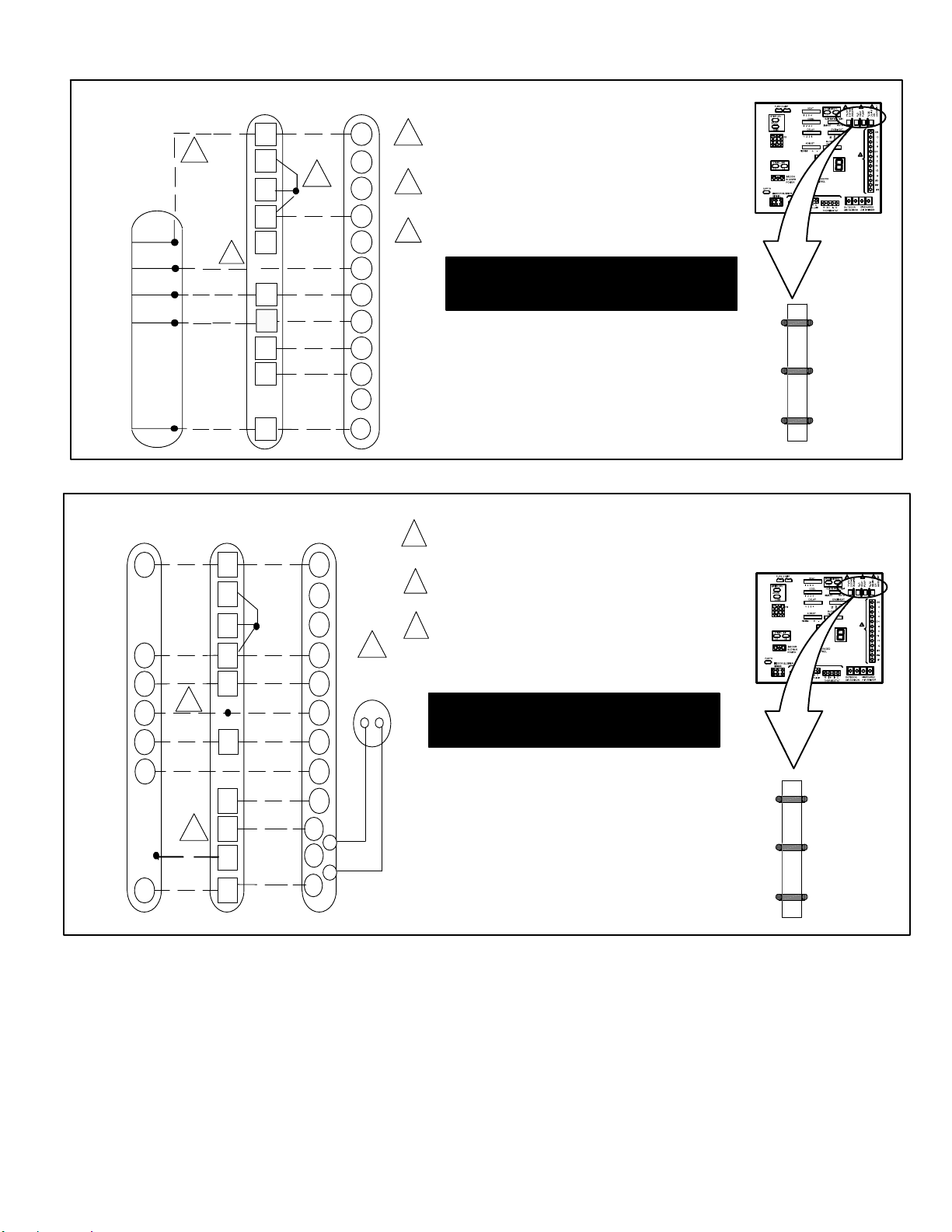
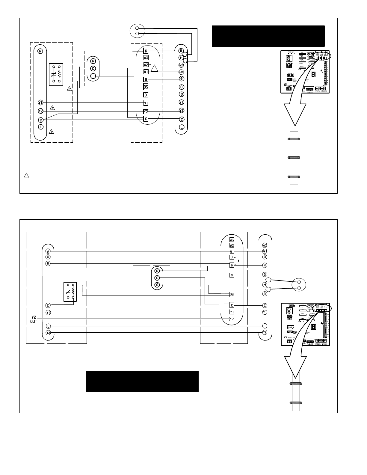
FIELD WIRING
AIR CONDITIONER
UNIT
(TWO-STAGE)
RED
BROWN
YELLOW
BLUE
BLACK
HEAT PUMP UNIT
(TWO-STAGE)
R
W1
L
Y1
CBX40UHV
R
2
W3
W2
W1
O
3
Y1
Y2
G
DS
C
COMFORTSENSET
1
Figure 6. Field Wiring — Cooling Application (Non-Communicating)
CBX40UHV
RR
W3
W2
W1 W1
OO
2
Y1
COMFORTSENSET
7000
H
W2
O
L
Y1
7000
R
H
W2
W1
O
L
Y1
Y2
G
D
B
C
1
O. D.
SENSOR
(X2658)
AIR HANDLER CONTROL COMES FROM FACTORY WITH A
METAL JUMPERS BETWEEN W1 TO W2 AND W2 TO W3.
1
R CONNECTION REQUIRED FOR AIR CONDITIONER UNIT WITH LSOM.
RESISTOR KIT (CAT # 47W97) IS REQUIRED WHEN CONNECTING THE
2
COMFORTSENSE 7000 WITH THE LSOM 2.
L CONNECTION WIRED ON UNITS WITH LSOM.
3
IMPORTANT — USE CARE WHEN CUTTING LINKS TO
PREVENT DAMAGE TO CONTROL. SEE FIGURE 12,
CBX40UHV JUMP AND LINK GUIDE FOR FURTHER
DETAILS.
CUT ON-BOARD LINK Y1-Y2 FOR TWO-STAGE AC
DO NOT CUT ON-BOARD LINK R -O.
CUT ON-BOARD LINK R-DS WHEN DEHUMIDIFICATION TERMINAL IS USED.
X2658 OUTDOOR SENSOR IS REQUIRED FOR OUTDOOR
TEMPERATURE DISPLAY, DEW POINT CONTROL, HEAT PUMP AND
1
DUAL FUEL BALANCE POINTS.
CONNECTED ON UNIT WITH LSOM. RESISTOR KIT (CAT #
2
47W97) IS REQUIRED WHEN CONNECTING THE
COMFORTSENSE 7000 WITH THE LSOM 2.
3
FIELD PROVIDED JUMPER BETWEEN Y2 OUT BL ON HEAT PUMP
TO Y2 ON CBX40UHV.
IMPORTANT — USE CARE WHEN CUTTING LINKS TO
PREVENT DAMAGE TO CONTROL. SEE FIGURE 12,
CBX40UHV JUMP AND LINK GUIDE FOR FURTHER
DETAILS.
AIR HANDLER
CONTROL
Y1-Y2
2-STAGE
COMPR
R-O
HEAT
PUMP
R-DS
DEHUM
OR
HARMONY
CUT FOR OPTION
Y2
OUT
BL
CC
CBX40UHV
Y2Y2
G
DS
3
Y2
G
D
T
B
T
C
CUT ON-BOARD LINK R-DS WHEN DEHUMIDIFICATION TERMINAL IS USED.
CUT ON-BOARD LINK Y1-Y2 FOR TWO-STAGE HP
CUT ON-BOARD LINK R -O.
Y1-Y2
2-STAGE
COMPR
R-O
HEAT
PUMP
R-DS
DEHUM
OR
HARMONY
CUT FOR OPTION
Figure 7. Field Wiring — Heat Pump (Non-Communicating)
Page 13
Page 14
OUTDOOR
SENSOR
(X2658)
RED
D
RED
BLK
PUR
EDA UNIT
CBX40UHV
PUR
BLK
FAN
RELAY
YEL
BLU
BLK
BRN
OUTDOOR UNIT
NOTES /1\
NOT REQUIRED FOR APPLICATIONS WITHOUT LSOM
/2\ NOT REQUIRED WITH SINGLE‐SPEED OUTDOOR FAN
NOT REQUIRED FOR SINGLE STAGE
/3\
AIR HANDLER CONTROL COMES FROM FACTORY WITH A METAL
4
JUMPERS BETWEEN W1 TO W2 AND W2 TO W3.
4
T
T
RESISTOR KIT (CAT # 47W97) IS REQUIRED
WHEN CONNECTING THE COMFORTSENSE
7000 WITH THE LSOM 2.
COMFORTSENSEt
7000 THERMOSTAT
CUT ON-BOARD LINK R-DS WHEN DEHUMIDIFICATION
IMPORTANT — USE CARE WHEN CUTTING LINKS TO
PREVENT DAMAGE TO CONTROL. SEE FIGURE 12,
CBX40UHV JUMP AND LINK GUIDE FOR FURTHER
DETAILS.
CUT ON-BOARD LINK Y1-Y2 FOR TWO-
DO NOT CUT ON-BOARD LINK R -O.
STAGE A/C
TERMINAL IS USED.
Y1-Y2
2-STAGE
COMPR
R-O
HEAT
PUMP
R-DS
DEHUM
OR
HARMONY
CUT FOR OPTION
Figure 8. Cooling Application — Humiditrol
OUTDOOR UNIT
RED
FAN RELAY (NOT REQUIRED
WITH SINGLE−SPEED
OUTDOOR FAN)
PURPLE
BLACK
YELLOW
BLUE
BROWN (NOT USED FOR APPLICATIONS WITHOUT LSOM
BLUE (NOT REQUIRED FOR SINGLE STAGE)
IMPORTANT — USE CARE WHEN CUTTING LINKS TO
PREVENT DAMAGE TO CONTROL. SEE FIGURE 12,
CBX40UHV JUMP AND LINK GUIDE FOR FURTHER
DETAILS.
®
and Second-Stage Outdoor Fan Relay Wiring
(Non-Communicating)
RED
BLACK
PURPLE
CUT ON-BOARD LINK Y1-Y2 FOR TWO-STAGE A/C ONLY
CUT ON-BOARD LINK R-DS WHEN DEHUMIDIFICATION
CBX40UHV
CUT ON-BOARD LINK R -O.
COMFORTSENSEt
7000 THERMOSTAT
T
T
TERMINAL IS USED.
OUTDOOR
SENSOR
(X2658)
Y1-Y2
2-STAGE
COMPR
R-O
HEAT
PUMP
R-DS
DEHUM
OR
HARMONY
CUT FOR OPTION
Figure 9. Heat Pump Application — Humiditrol
(Non-Communicating)
Page 14
®
and Second-Stage Outdoor Fan Relay Wiring
CBX40UHV
Page 15

Thermostat Connections
Table 2 (CBX40UHV-XXX-230-6-ALL)
Function
Indoor Control
Terminal Label
W1 (Input)
W2 (Input)
W3 (Input)
Y1 & Y2 (Input/
Output)
G (Input)
C
R The R terminal shall be capable of providing the power to the thermostat and all the associated loads.
O (Input/Output)
DS (Input)
DH (Output) The DH terminal provides a 24VAC output for dehumidification needs in communicating systems.
H (Output) The H terminal provides a 24VAC output for humidification needs in both communicating and non-communicating mode.
L (Input)
Non-Communicating
Room Thermostat
(Indoor and Outdoor -24 volts)
Indicates a first-stage heating demand.
This input is an anticipator for the ther
mostat.
Indicates a second-stage heating de
mand. W1 input must be active to recog
nize second-stage heat demand.
Indicates a third-stage heating demand.
W1 and W2 inputs must be active to rec
ognize third-stage heat demand.
Room thermostat inputs 24 volts to the
Y1 and Y2 terminals on the indoor con
trol. The 24 volt signal is then passed
through to the outdoor unit. During a
second-stage demand, both Y1 and Y2
are active. The Y1 terminal is connected
to Y2 by link (Solid jumper on control
that would be cut for 2 stage applica
tions)
Indicates a 24 volt indoor blower de
mand.
The C terminal shall interconnect the signal ground of the room thermostat with secondary transformer ground (TR) and
chassis ground (GND)
Room thermostat inputs 24 volts to the
O terminal on the indoor control. The O
terminal is connected to R by link (Solid
jumper on control that would be cut if
unit was a heat pump)
Used for Harmony III zoning systems, or
thermostat with dehumidification capa
bility. The DS terminal is connected to R
by link (Solid jumper on control that
would be cut if for the above applica
tions).
Harmony III control - This will allow the
control to vary the voltage signal to the
indoor blower motor to control required
CFM.
Dehumidification - Allow a 24 volt sig
nal on the DS to turn off and on the dehu
midification mode.
The L terminal is provided for connection to devices with Lennox System Operation Monitor (LSOM) capabilities. The control
interprets the fault signals and transmits them as an alarm message on the communication line. There are ten (10) identified
LSOM fault codes. Each is mapped to the communication Alarm codes.
Indoor Communicating
Outdoor Non-Communicating
N/A N/A
N/A N/A
N/A N/A
The room thermostat communicated
with the indoor control. The indoor con
trol outputs 24 volts on its Y1 and Y2
terminals which are hard wired to the
non-communicating outdoor unit.
In a communicating system, ”G” input to
indoor control is used by non-communi
cating IAQ devices (such as LVCS, HRV
or ERV) to ensure indoor blower de
mand.
The room thermostat communicated
with the indoor control. The indoor con
trol outputs 24 volts on its O terminals
which are hard wired to the non-com
municating outdoor unit. If there is 24
volts on O, the reversing valve will be
energized and the outdoor unit will run in
the cooling mode. If O does not have 24
volts, the outdoor unit will run in heating
mode.
N/A N/A
Full Communication
(Indoor & Outdoor)
In a full communicating system, no
wiring is required on Y1 and Y2 termi
nals.
In communicating system “G” input to
indoor control is used by non-communi
cating IAQ devices (such as LVCS, HRV
or ERV) to ensure indoor blower de
mand.
In a full communicating system, O termi
nal is not wired.
CBX40UHV
Page 15
Page 16
IMPORTANT
Before changing any clippable links or jumper settings,
make sure the motor has completely stopped. Any
changes will not take place while the motor is running.
Table 3. Air Handler Control Connections —
Communicating (CBX40UHV-XXX-230-6-ALL)
Label Label Function
R 24VAC
Thermostat
Outdoor Unit
Link
Table 4. Run Length — Communicating
Wire Run Length AWG # Insulation/Core Types
Maximum length of wiring
for all connections on the
RSBus is limited to 1500
feet (457 meters).
i+ RSbus data high connection
i- RSbus data low connection
C 24VAC command (ground)
R 24VAC
i+ RSbus data high connection
i- RSbus data low connection
C 24VAC command (ground)
i+
Not used.
i-
Thermostat Wire Length
(CBX40UHV-XXX-230-6-02)
18
Color-coded, temperature
rating 95
solid core. (Class II Rated
Wiring)
º
F (35ºC) minimum,
Table 5. Run Length — Non-Communicating
(CBX40UHV-XXX-230-6-01 and -02)
Wire Run Length AWG # Insulation/Core Types
Less than 100' (30m) 18
More than 100' (30m) 16
Color-coded, temperature
rating 95
solid core. (Class II Rated
Wiring)
º
F (35ºC) minimum,
Air Handler Control 9-Pin Connector
1. Air Handler ONLY - 2-wire harness (Wired to points 7
and 8) from the factory provides 230 volt power to Air
Handler Control.
2. Air Handler with ECB40 Electric Heat - 8-wire harness
(Wired as noted in table 6)
NOTE - See Figure 4
Table 6. Stages
Position &
Wire Color
1 red Heat stage 1 relay coil
2 orange Heat stage 2 relay coil
3 yellow Relay coil return
4 black Heat stage 3 relay coil
5 brown Heat stage 4 relay coil
6 blue Heat stage 5 relay coil
7 black L1 230VAC supply from heater kit
8 red L2 230 VAC supply from heater kit
9 Not Used
Function / Description
Page 16
CBX40UHV
Page 17
AIR HANDLER CONTROL BUTTON, DISPLAY AND
JUMPERS
Use figure 10 as reference for jumper settings. If any of the
reference jumpers are missing, the Air Handler Control will
display Error Code 130 as per table 13, and the Air Handler
Control will automatically use the factory default setting
show in figure 11)
Push Button
An on-board push button is provided for the purpose of
placing the Air Handler Control in different operation modes
and can be used to recall stored error codes. When button
is pushed and held, Air Handler Control will cycle through a
menu of options depending on current operating mode.
Every three seconds a new menu item will be displayed. If
the button is released while that item is shown on the
display, Air Handler Control will enter displayed operating
mode, or execute defined operation sequence for that
menu option. Once all items on menu have been displayed
the menu resumes from the beginning (if button is still held).
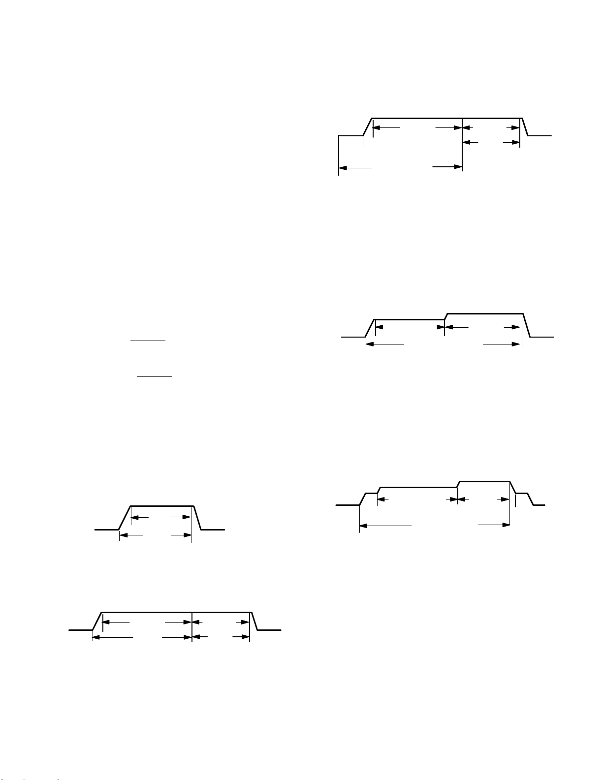
Delay Profile 1
Indoor blower cooling profile, delay for cooling and heat
pump operations are selected by placing the jumper in
appropriate position on five-pin header (four position
options).
S For heat pump heating operation only delay profiles 1
and 2 are applicable. If profiles 3 or 4 have been
selected, heat pump operation will use profile 1 only.
S For heat pump cooling operation all 4 profiles are
operational.
If the jumper is missing the AHC will activate the
Configuration Jumper is Missing alarm and will
automatically use the default factory setting. See figure 11
for jumper configurations.
A. When cool or heat demand is initiated, motor
ramps up to 100% and runs at 100% until demand
is satisfied.
B. Once demand is met, motor ramps down to stop.
B
100
A
Cooling — Air Conditioner and Heat Pump:
OFF
A
%CF
M
COOLING
DEMAND
Delay Profile 2
BC
100% CFM
COOL
ING
DEMAND
OFFOFF
100% CFM
45 SEC.
OFF
A. When cool demand is initiated, motor ramps up to
100% and runs at 100% until demand is satisfied.
B. Once demand is met, motor runs at 100% for 45
seconds.
C. Motor ramps down to stop.
Heating — Heat Pump only:
OFF
A
30 sec
delay
B
HEATING DEMAND
100% CFM
C
100% CFM
45 SEC.
D
A. When heat demand is initiated, 30 seconds motor
on delay starts
B. After the motor on delays expires, motor ramps up
to 100% and runs at 100% until demand is
satisfied.
C. Once demand is met, motor runs at 100% for 45
seconds.
D. Motor ramps down to stop.
Delay Profile 3
C
OFF
B
A
7 1/2 MIN
82%CFM
COOLING DEMAND
100% CFM
A. When cool demand is initiated, motor ramps up to
82%
B. Motor runs at 82% for approximately 7.5 minutes
and then ramp up to 100% (unless the demand has
been satisfied) and motor runs at 100% until
demand is satisfied.
C. Once demand is met, motor ramps down to stop
Delay Profile 4
C
OFF
A
B
1/2 MIN
50% CFM
7 1/2 MIN
82% CFM
COOLING DEMAND
100%
CFM
D
1/2 MIN
50% CFM
E
A. When cool demand is initiated, motor ramps up to
50%
B. Motor runs at 50% for 30 seconds and ramps up to
82%
C. Motor runs at 82% for approximately 7.5 minutes
and then ramp up to 100% (unless the demand has
been satisfied) and motor runs at 100% until
demand is satisfied.
D. Once demand is met, motor runs at 50% for 30
seconds.
E. Motor ramps down to stop
OFF
OFF
OFF
CBX40UHV
Page 17
Page 18
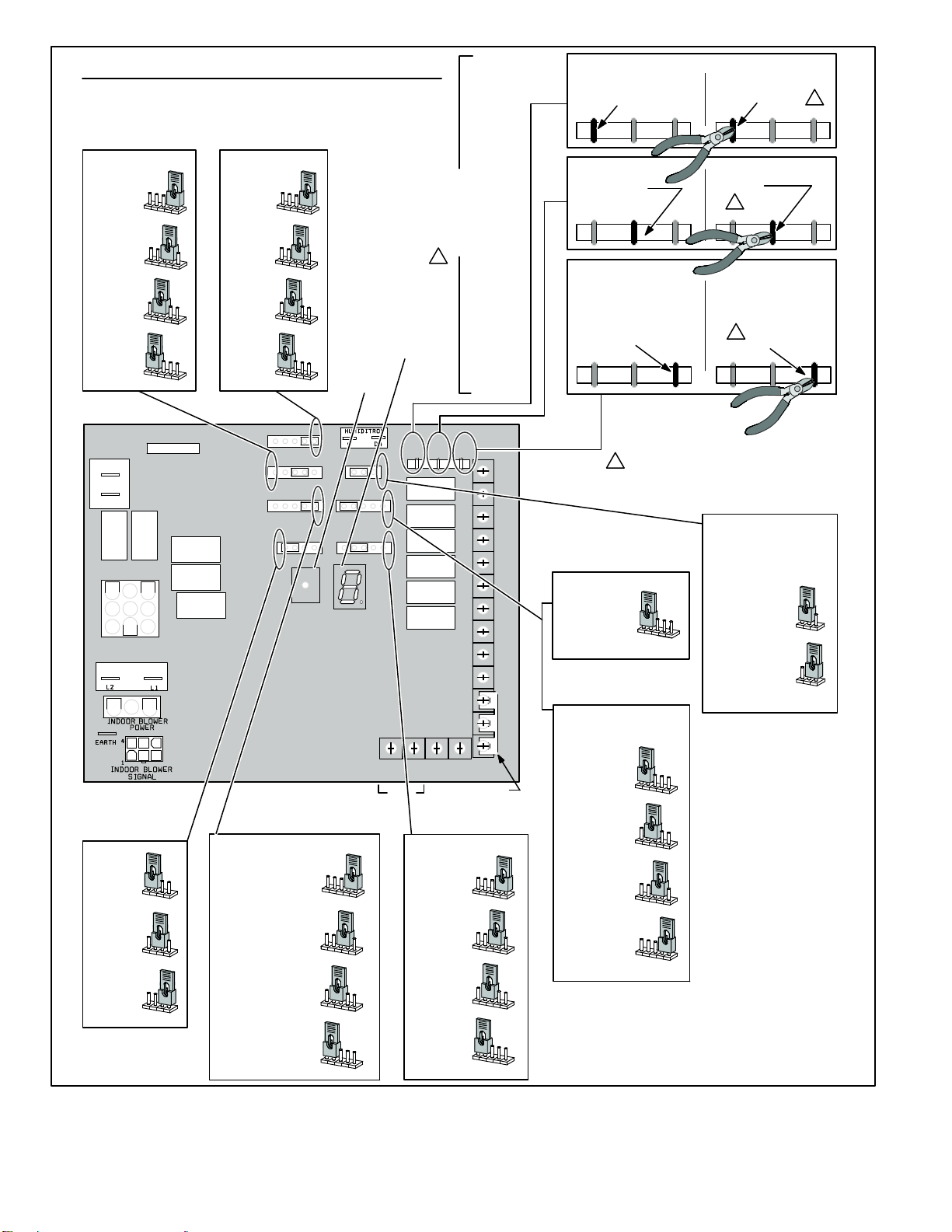
CBX40UHV JUMPER & LINK GUIDE
*
1−STG COMPRESSOR
2−STG COMPRESSOR
COOLING MODE
BLOWER SPEED
(COOLING & HP MODE)
HIGH
SPEED
1
2
3
4
*
MEDIUM−HIGH
SPEED
1
2
3
4
MEDIUM−LOW
SPEED
1
2
3
4
LOW
SPEED
1
2
3
4
FUSE 3 AMP
F1
3
XFMR
24V
24 VAC
COM
3
6
9
XFM LINE
1
4
7
BLOWER
ADJUST SELECTION
*
NORMAL
NORM
+
−
(+ 10%)
SETTING
NORM
+
−
(−10%)
SETTING
NORM
+
−
HEATING MODE
BLOWER SPEED
(ELECTRIC HT MODE)
*
HIGH
SPEED
1
2
3
4
MEDIUM−HIGH
SPEED
1
2
3
4
MEDIUM−LOW
SPEED
1
2
3
4
LOW
SPEED
J7
J9
J10
NORM + −
1
2
3
HEAT
1234
COOL
1234
DELAY
1234
ADJUST
4
PUSH
BUTTON
HUMIDIFICATION
J8
SMART AUTO
EVENHEAT
BLOWER
J11
ONLY CFM
1234
85
COOLING MODE
BLOWER RAMPING
(COOLING MODE UNLESS NOTED)
*
DELAY
PROFILE #4
OFF−50%−82%−
100%−50%−OFF
DELAY
PROFILE #3
OFF−82%−100%−OFF
DELAY
PROFILE #2
CLG
OFF−100%−100%−OFF
HP
OFF−30sOFF−100%−100% OFF
DELAY
PROFILE #1
OFF−100%−OFF
1
2
3
4
1
2
3
4
1
2
3
4
1
2
3
4
7−SEGMENT
LED DISPLAY
CUT FOR OPTION
Y1−Y2
2−STAGE
COMPR
J5
J4
115
100
130
OUTDOOR
SENSOR
FUTURE
USE
CONTINUOUS FAN
MODE BLOWER SPEED
MEDIUM−HIGH
MEDIUM−LOW
*
ON−BOARD LINK
OPTION SELECTION
1
OR
PUMP
DEHUM
R−O
HEAT
R−DS
HARMONY
DISCHARGE
AIR SENSOR
FACTORY
JUMPER
HIGH
SPEED
(100%)
1
SPEED
(70%)
1
SPEED
(38%)
1
LOW
SPEED
(28%)
1
2−STAGE
(JUMPERS Y1 to Y2)
COMPRESSOR LINK
HEAT PUMP LINK
(JUMPERS R to O)
HARMONY LINK
(JUMPERS R to DS)
DEHUMIDIFICATION−
STANDARD HEAT MODE
(STAGED BY TSTAT)
W3
W1 W2 G Y2 Y1 C R DH H L O DS
DEGREE TARGET
TEMPERATURE
2
3
4
2
3
4
2
3
4
2
3
4
Y1−Y2
DO NOT CUT
COMPR
2 STAGE
A/C UNIT
*
DO NOT CUT
R−0
HEAT
PUMP
NO HARMONY ZONING
*
OR NO
COMFORTSENSE 7000
W/ DS CONNECTION
DO NOT CUT
R−DS
DEHUM
−CUT ON−BOARD LINK (SOLDER TRACE)
1
THROUGH BOTH LAYERS ON THE CONTROL BOARD
IMPORTANT: USE CARE WHEN CUTTING LINKS TO
PREVENT DAMAGE TO CONTROL.
Y1−Y2
COMPR
2 STAGE
HEAT PUMP UNIT
CUT LINK
1
HARMONY ZONING
C0MFORTSENSE 7000
W/ DS CONNECTION
HARMONY
1
CUT LINK
or
COMPLETELY
CUT LINK
R−0
HEAT
OR
HUMIDIFICATION MODE
HUMIDIFICATION MODE
24VAC OUTPUT ON ”H”
(DEFAULT)
STANDARD
HEAT MODE
85
110
115
130
EVENHEATER® MODE
−ENABLED WITH OPTIONAL
DISCHARGE AIR SENSOR
*
85
DISCHARGE
100
DEGREE
TARGET
115
DEGREE
TARGET
130
DEGREE
TARGET
85
110
115
130
85
110
115
130
85
110
115
130
85
110
115
130
FACTORY DEFAULT SETTING
*
FOR HUMIDIFIER OR
ACCESSORY INTERLOCK
*
SMART MODE
− ”H” ENABLED WHEN
HEAT ACTIVE
(HP or ELECT. HT)
AUTO MODE
− ”H” ENABLED WHEN
BLOWER ACTIVE
& NO CLG
OR DEHUM
PUMP
SMART
SMART
R−DS
1
or
DEHUM
HARMONY
AUTO
AUTO
Figure 11. CBX40UHV-XXX-230-6-01
Page 18
CBX40UHV
Page 19
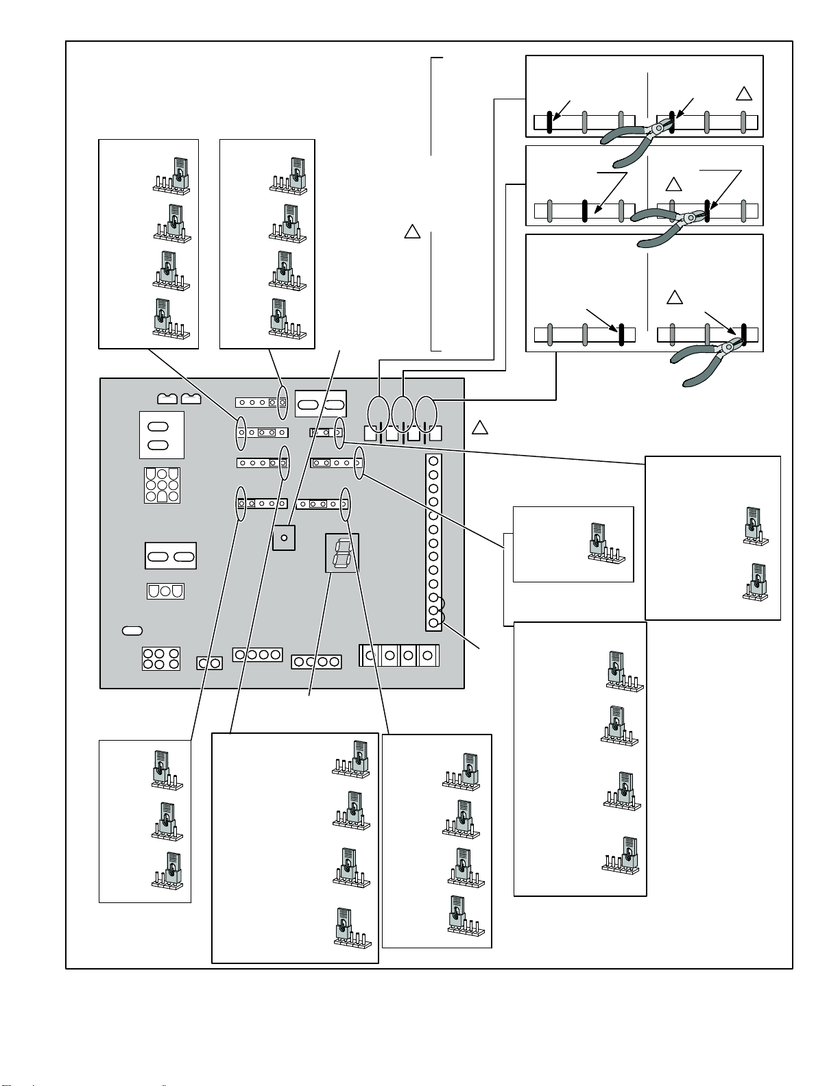
JUMPER & LINK GUIDE
COOLING MODE
BLOWER SPEED
(COOLING & HP MODE)
HIGH
SPEED
1
2
3
*
MEDIUM-HIGH
SPEED
1
2
3
MEDIUM-LOW
SPEED
1
2
3
LOW
SPEED
1
2
3
4
4
4
4
HEATING MODE
BLOWER SPEED
(ELECTRIC HT MODE)
*
HIGH
SPEED
1
2
3
MEDIUM-HIGH
SPEED
1
2
3
4
MEDIUM-LOW
SPEED
1
2
3
4
LOW
SPEED
1
2
3
4
4
PUSH
BUTTON
ON-BOARD LINK
OPTION SELECTION
1
2-STAGE
(JUMPERS Y1 to Y2)
COMPRESSOR LINK
HEAT PUMP LINK
(JUMPERS R to O)
HARMONY LINK
(JUMPERS R to DS)
DEHUMIDIFICATION-
*
1-STG COMPRESSOR
Y1-Y2
DO NOT CUT
COMPR
2 STAGE
A/C UNIT
*
DO NOT CUT
R-0
HEAT
NO HARMONY ZONING
*
OR NO
COMFORTSENSE 7000
W/ DS CONNECTION
DO NOT CUT
PUMP
R-DS
or
DEHUM
2-STG COMPRESSOR
Y1-Y2
2 STAGE
HEAT PUMP UNIT
CUT LINK
1
HARMONY ZONING
C0MFORTSENSE 7000
W/ DS CONNECTION
1
CUT LINK
HARMONY
CUT LINK
COMPR
R-0
HEAT
OR
PUMP
R-DS
1
or
DEHUM
HARMONY
FUSE 3 AMP
XFMR24V
24 VAC
COM
2
3
6
5
9
8
XFMR LINE
L2
L2
G
EARTH
INDOOR BLOWER
SIGNAL
456
12 3
BLOWER
ADJUST SELECTION
*
NORMAL
+
NORM
(+ 10%)
SETTING
+
NORM
(-10%)
SETTING
NORM+-
-
-
1
4
7
1234
1234
P8
L1
L1
INDOOR
BLOWER
POWER
I +
1234
ADJUST
NORM +
I + I -RC
OUTDOOR UNIT
I -
LINK
COOLING BLOWER RAMPING
(COOLING MODE UNLESS NOTED)
DELAYPROFILE #4
*
OFF-50%-82%100%-50%-OFF
PROFILE #3
DELAY
OFF-82%-100%-OFF
DELAY
PROFILE #2
CLG
OFF 100% DEMAND
SATISFIED 100% FOR 45
SECONDS OFF
HP
OFF 30 SECOND DELAY
100% DEMAND
SATISFIED 100% FOR 45
SECOND OFF
DELAY
PROFILE #1
OFF-100%-OFF
HEAT
COOL
DELAY
-
7-SEGMENT LED
HUMIDITROL
DH
C
HUMIDIFICATION
AUTO
SMART
EVENHEAT
85
100
BLOWER
ONLY CFM
1234
I + I -RC
THERMOSTAT
1
1
1
1
115
2
2
2
2
130
3
4
3
3
3
Y1-Y2
OUTDOOR
AIR SENSOR
4
4
4
2-STAGE
COMPR
R-O
HEAT
PUMP
DISCHARGE
AIR SENSOR
CONTINUOUS FAN
BLOWER SPEED
HIGH
SPEED
(100%)
MEDIUM-HIGH
SPEED
(70%)
* MEDIUM-LOW
SPEED
(38%)
LOW
SPEED
(28%)
OR
R-DS
DEHUM
HARMONY
-CUT ON-BOARD LINK (SOLDER TRACE) COMPLETELY
THROUGH BOTH LAYERS ON THE CONTROL BOARD
1
IMPORTANT: USE CARE WHEN CUTTING LINKS TO
PREVENT DAMAGE TO CONTROL.
DS
O
L
H
DH
R
C
Y1
Y2
G
W3
W2
W1
FACTORY
JUMPER
1
2
3
4
1
2
3
4
1
2
3
4
1
2
3
4
STANDARD HEAT MODE
(DEFAULT)
STANDARD
HEAT MODE
(STAGED BY TSTAT)
EVENHEATER MODE
-ENABLED WITH OPTIONAL
DISCHARGE AIR SENSOR
*
85
DEGREE TARGET
DISCHARGE
TEMPERATURE
100
DEGREE
TARGET
115
DEGREE
TARGET
130
DEGREE
TARGET
* INDICATES FACTORY DEFAULT SETTING
85
110
115
85
85
85
85
130
110
110
110
110
115
115
115
115
130
130
130
130
HUMIDIFICATION MODE
HUMIDIFICATION MODE
24VAC OUTPUT ON ”H”
FOR HUMIDIFIER OR
ACCESSORY INTERLOCK
*
SMART MODE
- ”H” ENABLED WHEN
HEAT ACTIVE
(HP or ELECT. HT)
AUTO MODE
- ”H” ENABLED WHEN
BLOWER ACTIVE
& NO CLG
OR DEHUM
SMART
SMART
AUTO
AUTO
CBX40UHV
Figure 12. Air Handler Configuration (CBX40UHV-XXX-230-6-02 or higher)
Page 19
Page 20

VARIABLE SPEED ECM BLOWER MOTOR
Blower Motor (B3)
To Remove Blower From Unit: Remove wiring jack plug and
three screws and slide blower out.
Figure 13. Blower Motor (B3)
WARNING
During blower operation, the ECM motor emits energy
that may interfere with pacemaker operation. Interfer
ence is reduced by both the sheet metal cabinet and dis
tance.
The ECM (electronically commutated motor) communicates
with the air handler control via a 2-way serial connection. The
motor receives all necessary functional parameters from the
air handler control and does not rely on a factory program like
traditional variable speed motors. The wiring harness
connects the motor to the air handler control. See wiring
diagram regarding wiring harness. A solid‐ state control ler
is permanently attached to the motor. The controller is
primarily an AC to DC converter. Converted DC power is
used to drive the motor. The controller contains a
microprocessor which monitors varying conditions
inside the motor (such as motor workload). Because this
motor has a permanent magnet rotor it does not need
brushes like conventional DC motors]
Internal components are shown in figure 14. The stator
windings are split into three poles which are electrically
connected to the controller. This arrangement allows motor
windings to turn on and off in sequence by the controller.
IMPORTANT
Earlier ECM motors used on other Lennox air handler
models are not interchangeable with motors used on the
CBX40UHV line.
The controller uses sensing devices to sense what position
the rotor is in at any given time. By sensing the position of the
rotor and then switching the motor windings on and off in
sequence, the rotor shaft turns the blower.
All CBX40UHV blower motors use single phase power.
An external run capacitor is not used. The motor uses
permanently lubricated ball‐type bearings.
STATOR
CONTROLLER
Figure 14. Blower Motor Components
Internal Operation
The motor is controlled via serial communication between
the integrated control and the controller permanently
attached to the motor shell. The messages sent back and
forth between the two controls serve to communicate
rotational direction, demand, motor size, current draw,
torque, and RPM, among other variables.
Motor RPM is continually adjusted internally to maintain
constant static pressure against the blower wheel. The
controller monitors the static work load on the motor and motor
amp‐draw to determine the amount of RPM adjustment.
Blower RPM may be adjusted any amount in order to maintain
a constant cfm as shown in Blower Ratings Tables. The cfm
remains relatively stable over a broad range of static pressure.
Since the blower constantly adjusts RPM to maintain a
specified cfm, motor RPM is not rated. Hence, the terms “cool
speed”, “heat speed ” or “speed tap” in this manual, on the unit
wiring diagram and on blower B3, refer to blower cfm
regardless of motor RPM.
Initial Power Up
When line voltage is applied to B3, there will be a large inrush
of power lasting less than 1/4 second. This inrush charges a
bank of DC filter capacitors inside the controller. If the
disconnect switch is bounced when the disconnect is closed,
the disconnect contacts may become welded. Try not to
bounce the disconnect switch when applying power to the unit.
Motor Start‐Up
When B3 begins start‐up, the motor gently vibrates back and
forth for a moment. This is normal. During this time the
electronic controller is determining the exact position of the
rotor. Once the motor begins turning, the controller slowly
eases the motor up to speed (this is called “soft‐start”). The
motor may take as long as 60 seconds to reach full speed. If
the motor does not reach 200RPM within 13 seconds, the
motor shuts down. Then the motor will immediately attempt a
restart. The shutdown feature provides protection in case of a
frozen bearing or blocked blower wheel. The motor may
attempt to start eight times. If the motor does not start after the
eighth try, the controller locks out. Reset controller by
momentarily turning off power to unit.
(WINDINGS)
BEARING
OUTPUT
SHAFT
ROTOR
Page 20
CBX40UHV
Page 21

The DC filter capacitors inside the controller are connected
electrically to the motor supply wires. The capacitors take
approximately 5 minutes to discharge when the disconnect
is opened. For this reason it is necessary to wait at least 5
minutes after turning off power to the unit before
attempting to service motor.
4. Test is complete. Remove jumpers and reconnect
plugs.
Another option is to use the TECMate PRO with the 16 to
4 pin adaptor. The use of the TECMate PRO isolates the
motor from the integrated control. Follow the instructions
provided with the kit. If the motor runs do not replace.
DANGER
Disconnect power from unit and wait
at least five minutes to allow capaci
tors to discharge before attempting to
service motor. Failure to wait may
cause personal injury or death.
Indoor Blower Motor (B3) Control Troubleshooting
(Regal-Beloit)
To verify motor operation see steps below and figure 15.
NOTE: If the communication channel is disrupted (loss of
communication and and 24VAC) to the air handler control,
the motor will continue to operate at its current mode. This
means, if the motor is currently in idle, it will stay in idle
mode; if it is currently running, it will stay running at the
current operating point.
Check Power to Motor
1. Remove J48 (5-pin power plug) from P48 on the motor.
2. With the power on at the air handler, use a test meter to
verify 240V between pins 4 and 5 on J48.
3. Reconnect J48 to P48 on the motor.
APPLY TEST SIGNAL FOR MOTOR OPERATION
1. Remove J49 (4-pin low voltage connector) from P49 on
the motor.
2. Using test jumpers, apply 24V to pins 3 and 4 on P49 on
the motor.
Note: Do not apply 24V to pins 2 and 4 on P49. Doing so
will cause permanent damage to the motor.
3. Motor should run at 75%.
P48 5 PIN
J48 5 Pin
J49 4 Pin
P49 4 PIN
MOTOR with INTEGRATED
CONTROLLER
J48 5 Pin Line Voltage Connector
J49 4 Pin Control Connector
Figure 15. Regal-Beloit — Blower B3 Harness
Connectors
CBX40UHV
Page 21
Page 22

P48 5 Pin
P49 4 Pin
J48 Connector
installed on motor
P49 4 Pin
P48 5 PIN
1
2
3
0
4
P49 4 PIN
5
120v
230v
J48 Connector
Indoor Blower Motor (B3) Control
Troubleshooting (Emerson)
NOTE: If the communication channel is disrupted (loss of
communication and and 24VAC) to the air handler control,
the motor will continue to operate at its current mode. This
means, if the motor is currently in idle, it will stay in idle
mode; if it is currently running, it will stay running at the
current operating point.
1. Disconnect three-wire harness from motor control
module.
A. If the plug terminals inside the module are
damaged.
B. If terminals are not damaged, proceed to next step.
2. Inspect the negative temperature coefficient (NTC)
thermistor (see figure 18) for any cracks or breakage.
A. If damaged, replace control.
B. If no damage is detected, proceed to next step.
3. Check the capacitors for any damage. Inspect for:
A. Bulging or swelling caps. If caps are bulging or
swollen, replace control.
B. If no damage is detected, proceed to next step.
4. Check resistance between each of the three pins on the
control module jack (see figure 18). Resistance
between any two terminals should be greater than 100
K ohms.
A. If resistance is less than 100 K ohms, replace
control.
B. If no damage is detected, proceed to next step.
NOTE — If your ohm meter is not an auto-ranging type,
please set it to the highest ohm scale (100 K ohms or
greater).
Scale
2 M
200 K
20 K
2 K
200 two hundred ohms 0 - 200
Measurement range in
words
two megohm-two million
ohms
two hundred kilo-ohm-two
hundred thousand ohms
twenty kilo-ohm-twenty
thousand ohms
two kilo-ohm two-thousand
ohms
ohms
0 - 2,000,000
0 - 200,000
0 - 20,000
0 - 2,000
24v Transformer
J49 Connector
Figure 16. Regal-Beloit — Troubleshooting
Page 22
Figure 17. Typical Digital Multimeter
CBX40UHV
Page 23

CONTROL MODULE
3-PIN JACK
B. If there is no damage, proceed to next step.
3. Check resistance between each of the three-phase
terminals in the motor harness as illustrated in figure
19. Resistance between any two contacts should be
equal. If resistance between any two contacts are not
equal, or if any resistance shows open or
short-circuited, replace the motor.
MOTOR 3-PIN
PLUG
THERMISTOR
NTC
Figure 18. Module Test (Emerson)
Additional Indoor Blower Motor (B3) Troubleshooting
1. If motor shaft spins freely in both directions, proceed to
next step. If not, replace motor.
2. Check the motor to control harness for any damage.
A. If harness or terminals are damaged replace the
motor.
P48 (5-PIN)
P48 5 Pin
Figure 19. Motor Test (Emerson)
P49 (4-PIN)
MOTOR
J48 5 Pin Line Voltage Connector
CONTROL MODULE
P49 4 Pin
CBX40UHV
J49 4 Pin Control Connector
Figure 20. Indoor Blower Motor (B3) Control Connections (Emerson)
Page 23
Page 24

P48 (5-PIN)
HARNESS
P49 (4-PIN) HARNESS
P48 (5-PIN)
HARNESS
P48 (5-PIN)
HARNESS
MOTOR
CONTROL MODULE
120v
0
Figure 21. J48 Test (Emerson)
P49 (4-PIN) HARNESS
230v
P49 4 Pin
1
2
3
4
5
J48 Connector
P48 (5-PIN)
HARNESS
MOTOR
CONTROL MODULE
Figure 22. J49 Test (Emerson)
J49 4 Pin
Page 24
J49 Connector
24v Transformer
CBX40UHV
Page 25

OPTIONAL ECB40 ELECTRIC HEAT
3. Terminal Strip (TB2)
Match-ups and Ratings
The tables on the following pages show all approved
CBX40UHV to ECB40 matchups and electrical ratings.
Electric Heat Components
ECB40 parts arrangement is shown in figure 23. All electric
heat sections consist of components mounted to the electric
heat vestibule panel and electric heating elements exposed
directly to the air stream. ECB units are equipped with circuit
breakers or a terminal blocks. The circuit breakers are
designated by CB in the model number.
1. Primary (S15) and Secondary (S20) Temperature
Limits
Each stage of the electric heat is protected by a
primary (S15) and secondary (S20) high temperature
limit. Both S15 and S20 are located in the same housing.
Each stage uses the same style of limits. Both the primary
and secondary limits are wired in series with a heat
element. When either S15 or S20 opens, the
corresponding heat element is de‐energized. All
other heating elements remain energized. The primary
high temperature limit opens on a temperature rise and
closes on a temperature fall. The secondary limit opens on
a temperature rise but must be replaced. See table 7 for
set points.
TABLE 7
Limit
Open° Close°
S15 150_F + 5 110 + 9
S20 333_F + 10_F Replace limit
2. Electric Heat Relays (K32, K33, K34, K35 and K36)
Relays K32, K33, K34, K35 and K36 are N.O. relays
located on the electric heat vestibule panel and are
energized by a 24V heating demand (W1, W2, and W3)
via jack/plug 2 (J2), which is used to connect electric heat
to the blower coil control circuit. T h e rel a y s en e r gize
different stages of heat, as well as the blower. The
blower is always first on and last off.
For the electric heat sections without circuit breakers or
fuses, line voltage connections are made to terminal strip
TB2. The terminal strip is located in the lower left corner of
the electric heat vestibule panel. Single‐phase electric
heat uses two pole terminal strips; while three‐phase
electric heat uses three pole terminal strips.
4. Circuit Breaker (CB1, CB2 and CB3)
Line voltage connections are made to circuit breakers
CB1,CB2 and CB3 in the electric heat sections with circuit
breakers (designated by CB in the model numbers).
Tables in the following pages show the amp rating for each
circuit breaker used. Single‐phase electric heat uses two
pole circuit breakers; while three‐phase electric heat uses
three pole circuit breakers.
Note: Electric Heat Circuit Breakers are sized for 240VAC
operation. Electric heaters operating at voltages other than
240VAC may require the factory installed circuit breaker be
replaced with a field installed circuit breaker. See
Maximum Overcurrent Protection column in the Electric
Heat Tables to determine if a circuit breaker change is
required.
Note: Do not remove patch plate or insulation on units
without circuit breakers!!
5. Heating Elements (HE1 through HE6)
Heating elements are composed of helix wound bare
nichrome wire exposed directly to the air stream. The
elements are supported by insulators mounted to the wi re
frame. For single phase applications, one element is
used per stage. Each stage is energized
independently by the corresponding relay located
on the electric heat vestibule arranged in a three
phase delta. Once energized, heat transfer is
instantaneous. High temperature protection is
provided by primary and secondary high
temperature limits.
CBX40UHV
Page 25
Page 26

ECB40-9CB P VOLTAGE SHOWN
Elements HE1 and HE2
Location of CB1
Relay K33
Primary Limit S15 and
Secondary Limit S20
Relay K32
Figure 23. Electric Heat
Page 26
CBX40UHV
Page 27

ELECTRIC HEAT DATA - CBX40UHV-024 AND CBX40UHV-030
SINGLE PHASE ELECTRIC HEAT CBX40UHV-024 CBX40UHV-030
3
Model Number
No.
of
Stages
Volts
InputkWInput
1
Btuh
Input
2
Blower
Motor
Full Load
Amps
3
Minimum
Circuit
Ampacity
5
Maximum
Overcurrent
Protection
208 1.9 6,400 4.0 17 20 - - - - - - - - - - - -
2.5 kW
4 lbs.
ECB40-2.5 (34W86)
Terminal Block
1
220 2.1 7,200 4.0 17 20 - - - - - - - - - - - -
230 2.3 7,800 4.0 18 20 - - - - - - - - - - - -
240 2.5 8,500 4.0 18 20 - - - - - - - - - - - -
4
25 23 - - -4 25 - - -
4
25 24 - - -
4
25 25 - - -4 25 - - -
4
30 28 - - -4 30 - - -
4
30 29 - - -4 30 - - -
4
30 30 - - -4 30 - - -
4
35 32 - - -4 35 - - -
4
35 33 - - -4 35 - - -
4
35 35 - - -
4
45 41 - - -4 45 - - -
4
45 43 - - -4 45 - - -
4
45 45 - - -4 45 - - -
4
50 46 - - -4 50 - - -
4
50 48 - - -4 50 - - -
4 kW
4 lbs.
5 kW
4 lbs.
6 kW
4 lbs.
8 kW
5 lbs.
9 kW
5 lbs.
ECB40-4 (55W89)
Terminal Block
ECB40-4CB (55W90)
30A Circuit breaker
ECB40-5 (34W87)
Terminal Block
ECB40-5CB (34W90)
35A Circuit breaker
EB40-6 (34W88)
Terminal Block
ECB40-6CB (34W91)
40A Circuit breaker
ECB40-8 (34W89)
Terminal Block
ECB40-8CB (34W92)
50A Circuit breaker
ECB40-9CB (34W93)
60A Circuit breaker
208 3.0 10,250 4.0 23
1
220 3.4 11,450 4.0 24
230 3.7 12,550 4.0 25
240 4.0 13,650 4.0 26 30 26 - - - 30 - - -
208 3.8 12,800 4.0 28
1
220 4.2 14,300 4.0 29
230 4.6 15,700 4.0 30
240 5.0 17,100 4.0 31 35 31 - - - 35 - - -
208 4.5 15,400 4.0 32
1
220 5.0 17,100 4.0 33
230 5.5 18,800 4.0 35
240 6.0 20,500 4.0 37 40 37 - - - 40 - - -
208 6.0 20,500 4.0 41
1
220 6.7 22,900 4.0 43
230 7.3 25,100 4.0 45
240 8.0 27,300 4.0 47 50 47 - - - 50 - - -
208 6.8 23,100 4.0 46
2
220 7.6 25,800 4.0 48
230 8.3 28,200 4.0 50 60 50 - - - 60 - - -
240 9.0 30,700 4.0 52 60 52 - - - 60 - - -
208 9.4 32,000 4.0 - - - - - - 24 38
12.5 kW
10 lbs.
ECB40-12.5CB (34W94)
(1) 30A & (1) 45A Circuit
breaker
2
220 10.5 35,800 4.0 - - - - - - 25 40
230 11.5 39,200 4.0 - - - - - - 26 42 30 45
240 12.5 42,600 4.0 - - - - - - 27 44 30 45
208 11.3 38,400 4.0 - - - - - - 28 45
15 kW
12 lbs.
ECB40-15CB (34W95)
(1) 35A & (1) 60A Circuit
breaker
2
220 12.6 43,000 4.0 - - - - - - 29 48
230 13.8 47,000 4.0 - - - - - - 30 50
240 15.0 51,200 4.0 - - - - - - 31 52 35 60
NOTE - Circuit 1 Minimum Circuit Ampacity includes the Blower Motor Full Load Amps.
1
Electric heater capacity only - does not include additional blower motor heat capacity.
2
Amps shown are for blower motor only.
3
Refer to National or Canadian Electrical Code manual to determine wire, fuse and disconnect size requirements. Use wires suitable for at least 167°F.
4
Bold text indicates that the circuit breaker on “CB” circuit breaker models must be replaced with size noted. See Table on Page 6.
5
HACR type circuit breaker or fuse.
Minimum
Circuit
Ampacity
Circuit Circuit
1 2 1 2
5
Maximum
Overcurrent
Protection
4
25 - - -
4
35 - - -
4
25
4
254 40
4
304 45
4
304 50
4
30
4
40
4
50
CBX40UHV
Page 27
Page 28

ELECTRIC HEAT DATA - CBX40UHV-036
SINGLE PHASE ELECTRIC HEAT CBX40UHV-036
3
Minimum
Circuit
Ampacity
Circuit Circuit
1 2 1 2
Model Number
ECB40-4 (55W89)
4 kW
4 lbs.
Terminal Block
ECB40-4CB (55W90)
35A Circuit breaker
ECB40-5 (34W87)
5 kW
4 lbs.
Terminal Block
ECB40-5CB (34W90)
35A Circuit breaker
ECB40-6 (34W88)
6 kW
4 lbs.
Terminal Block
ECB40-6CB (34W91)
40A Circuit breaker
ECB40-8 (34W89)
8 kW
5 lbs.
Terminal Block
ECB40-8CB (34W92)
50A Circuit breaker
9 kW
5 lbs.
12.5
kW
10 lbs.
15 kW
12 lbs.
20 kW
19 lbs.
ECB40-9CB (34W93)
60A Circuit breaker
ECB40-12.5CB (34W94)
(1) 30A & (1) 45A Circuit
breaker
ECB40-15CB (34W95)
(1) 35A & (1) 60A Circuit
breaker
ECB40-20CB (34W96)
(2) 60A Circuit breaker
THREE PHASE ELECTRIC HEAT
8 kW
5 lbs.
10 kW
6 lbs.
15 kW
12 lbs.
ECB40-8 (34W98)
Terminal Block
ECB40-10 (34W99)
Terminal Block
ECB40-15CB (35W00)
50A Circuit breaker
No.
of
Stages
1
1
1
1
2
2
2
2
1
1
1
2
Volts
Input
kW
Input
1
Btuh
Input
Blower
Motor Full
Load Amps
208 3.0 10,250 5.6 25 - - -
220 3.4 11,450 5.6 26 - - -
230 3.7 12,550 5.6 27 - - -
240 4.0 13,650 5.6 28 - - -
208 3.8 12,800 5.6 30 - - -
220 4.2 14,300 5.6 31 - - - 35 - - -
230 4.6 15,700 5.6 32 - - - 35 - - -
240 5.0 17,100 5.6 34 - - - 35 - - -
208 4.5 15,400 5.6 35 - - -
220 5.0 17,100 5.6 35 - - -
230 5.5 18,800 5.6 37 - - - 40 - - -
240 6.0 20,500 5.6 39 - - - 40 - - -
208 6.0 20,500 5.6 44 - - -
220 6.7 22,900 5.6 45 - - -
230 7.3 25,100 5.6 47 - - - 50 - - -
240 8.0 27,300 5.6 49 - - - 50 - - -
208 6.8 23,100 5.6 48 - - -
220 7.6 25,800 5.6 50 - - -
230 8.3 28,200 5.6 52 - - - 60 - - -
240 9.0 30,700 5.6 54 - - - 60 - - -
208 9.4 32,000 5.6 26 38 30
220 10.5 35,800 5.6 27 40 30
230 11.5 39,200 5.6 28 42 30 45
240 12.5 42,600 5.6 29 44 30 45
208 11.3 38,400 5.6 30 45
220 12.6 43,000 5.6 31 48 35
230 13.8 47,000 5.6 32 50 35
240 15.0 51,200 5.6 33 52 35 60
208 15.0 51,200 5.6 48 50
220 16.8 57,300 5.6 50 53
230 18.4 62,700 5.6 52 55 60 60
240 20.0 68,200 5.6 54 57 60 60
208 6.0 20,500 5.6 28 - - - 30 - - -
220 6.7 22,900 5.6 29 - - - 30 - - -
230 7.3 25,100 5.6 30 - - - 30 - - -
240 8.0 27,300 5.6 32 - - - 35 - - -
208 7.5 25,600 5.6 34 - - - 35 - - -
220 8.4 28,700 5.6 35 - - - 35 - - -
230 9.2 31,400 5.6 36 - - - 40 - - -
240 10.0 34,100 5.6 38 - - - 40 - - -
208 11.3 38,400 5.6 47 - - - 50 - - -
220 12.6 43,000 5.6 48 - - - 50 - - -
230 13.5 47,000 5.6 50 - - - 50 - - -
240 15.0 51,200 5.6 53 - - -
5
Maximum
Overcurrent
Protection
4
25 - - -
4
30 - - -
4
30 - - -
4
30 - - -
4
30 - - -
4
35 - - -
4
35 - - -
4
45 - - -
4
45 - - -
4
50 - - -
4
50 - - -
4
30
4
50
4
50 60
4
60 - - -
4
40
4
40
4
45
4
50
4
50
4
50
Page 28
CBX40UHV
Page 29

ELECTRIC HEAT DATA - CBX40UHV-036 (Continued)
THREE PHASE ELECTRIC HEAT CBX40UHV-036
Model Number
No.
of
Stages
Volts
InputkWInput
1
Btuh
Input
2
Blower
Motor Full
Load Amps
3
Minimum
Circuit
Ampacity
5
Maximum
Overcurrent
Protection
208 15.0 51,200 5.6 33 26 35
20 kW
19 lbs.
NOTE - Circuit 1 Minimum Circuit Ampacity includes the Blower Motor Full Load Amps.
1
Electric heater capacity only - does not include additional blower motor heat capacity.
2
Amps shown are for blower motor only.
3
Refer to National or Canadian Electrical Code manual to determine wire, fuse and disconnect size requirements. Use wires suitable for at least 167°F.
4
Bold text indicates that the circuit breaker on “CB” circuit breaker models must be replaced with size noted. See Table on Page 6.
5
HACR type circuit breaker or fuse.
ECB40-20CB (35W01)
(2) 35A Circuit breaker
2
220 16.8 57,300 5.6 35 28 35
230 18.4 62,700 5.6 36 29
240 20.0 68,200 5.6 37 30
4
4
40
40 35
ELECTRIC HEAT DATA - CBX40UHV-042, CBX40UHV-048, AND CBX40UHV-060
SINGLE PHASE ELECTRIC HEAT CBX40UHV-042, CBX40UHV-048 and CBX40UHV-060
Model Number
No. of
Stages
Volts
InputkWInput
1
Btuh
Input
2
Blower
Motor Full
Load
Amps
3
Minimum
Circuit Ampacity
Circuit1Circuit2Circuit3Circuit1Circuit2Circuit
5
Maximum
Overcurrent Protection
4
30
4
30
4
30
3
4 kW
4 lbs.
5 kW
4 lbs.
6 kW
4 lbs.
8 kW
5 lbs.
9 kW
5 lbs.
12.5 kW
10 lbs.
15 kW
12 lbs.
ECB40-4 (55W89)
Terminal Block
ECB40-4CB (55W90)
35A Circuit breaker
ECB40-5 (34W87)
Terminal Block
ECB40-5CB (34W90)
35A Circuit breaker
ECB40-6 (34W88)
Terminal Block
ECB40-6CB (34W91)
40A Circuit breaker
ECB40-8 (34W89)
Terminal Block
ECB40-8CB (34W92)
50A Circuit breaker
ECB40-9CB (34W93)
60A Circuit breaker
ECB40-12.5CB (34W94)
(1) 30A & (1) 45A Circuit
breaker
ECB40-15CB (34W95)
(1) 35A & (1) 60A Circuit
breaker
4
1 208 3.0 10,250 7.4 27 - - - - - -
30 - - - - - -
1 208 3.8 12,800 7.4 32 - - - - - - 35 - - - - - -
1 208 4.5 15,400 7.4 37 - - - - - - 40 - - - - - -
1 208 6.0 20,500 7.4 46 - - - - - - 50 - - - - - -
2 208 6.8 23,100 7.4 51 - - - - - - 60 - - - - - -
4
2 208 9.4 32,000 7.4 29 38 - - - 30
2 208 11.3 38,400 7.4 32 45 - - - 35
40 - - -
4
45 - - -
20 kW
19 lbs.
25 kW
19 lbs.
ECB40-20CB (34W96)
(2) 60A Circuit breaker
ECB40-25CB (34W97)
(1) 60A & (2) 45A Circuit
breaker
CBX40UHV
2 208 15.0 51,200 7.4 50 50 - - -
3 208 18.8 64,100 7.4 47 38 38
Page 29
4
4
50
50
4
50 - - -
4
40
4
40
Page 30

ELECTRIC HEAT DATA - CBX40UHV-042, CBX40UHV-048, AND CBX40UHV-060 (Continued)
SINGLE PHASE ELECTRIC HEAT CBX40UHV-042, CBX40UHV-048 and CBX40UHV-060
3
Minimum
Circuit Ampacity
Model Number
No. of
Stages
Volts
InputkWInput
1
Btuh
Input
2
Blower
Motor Full
Load
Amps
Circuit1Circuit2Circuit3Circuit1Circuit2Circuit
THREE PHASE ELECTRIC HEAT
208 6.0 20,500 7.4 30 - - - - - - 35 - - - - - -
8 kW
5 lbs.
ECB40-8 (34W98)
Terminal block
1
220 6.7 22,900 7.4 31 - - - - - - 35 - - - - - -
230 7.3 25,100 7.4 32 - - - - - - 35 - - - - - -
240 8.0 27,300 7.4 33 - - - - - - 35 - - - - - -
208 7.5 25,600 7.4 36 - - - - - - 40 - - - - - -
10 kW
6 lbs.
ECB40-10 (34W99)
Terminal block
1
220 8.4 28,700 7.4 37 - - - - - - 40 - - - - - -
230 9.2 31,400 7.4 38 - - - - - - 40 - - - - - -
240 10.0 34,100 7.4 40 - - - - - - 40 - - - - - -
208 11.3 38,400 7.4 49 - - - - - - 50 - - - - - -
15 kW
12 lbs.
ECB40-15CB (35W00)
50A Circuit breaker
1
220 12.6 43,000 7.4 51 - - - - - -
230 13.5 47,000 7.4 52 - - - - - -
240 15.0 51,200 7.4 55 - - - - - -
208 15.0 51,200 7.4 36 26 - - -
20 kW
19 lbs.
ECB40-20CB (35W01)
(2) 35A Circuit breaker
2
220 16.8 57,300 7.4 37 28 - - -
230 18.4 62,700 7.4 38 29 - - -
240 20.0 68,200 7.4 40 30 - - -
208 18.8 64,100 7.4 42 33 - - -
25 kW
19 lbs.
ECB40-25CB (35W02)
(1) 50A & (1) 40A Circuit
breaker
2
220 21.0 71,700 7.4 44 34 - - -
230 23.0 78,300 7.4 45 36 - - - 50 40 - - -
240 25.0 85,300 7.4 47 38 - - - 50 40 - - -
NOTE - Circuit 1 Minimum Circuit Ampacity includes the Blower Motor Full Load Amps.
1
Electric heater capacity only - does not include additional blower motor heat capacity.
2
Amps shown are for blower motor only.
3
Refer to National or Canadian Electrical Code manual to determine wire, fuse and disconnect size requirements. Use wires suitable for at least 167°F.
4
Bold text indicates that the circuit breaker on “CB” circuit breaker models must be replaced with size noted. See Table on Page 6.
5
HACR type circuit breaker or fuse.
5
Maximum
Overcurrent Protection
4
60 - - - - - -
4
60 - - - - - -
4
60 - - - - - -
4
4
4
4
4
4
4
40
40
40
30 - - -
4
30 - - -
4
30 - - -
40 35 - - -
4
45
45
35 - - -
4
35 - - -
3
OPTIONAL HUMIDITY CONTROL (A20)
®
ComfortSense
7000 Thermostat
The Lennox ComfortSenset 7000 thermostat (shown
below) monitors indoor humidity conditions and creates a
dehumidification demand in response to indoor humidity
just as it creates a cooling demand in response to indoor
temperature. This thermostat adjusts compressor speed
and indoor blower speed to maintain humidity at a
comfortable level.
COOLING
TUE OCT 23 1:15PM
Principles of cooling with drier air
The humidity comfort range for humans is between 40 and
60 percent relative humidity (RH). 50% RH is the
recommended initial setpoint until personal comfort level is
established. The personal comfort level will vary with
humidity as with temperature. For example, if air at 75ºF
(24ºC) and 50% RH is changed to 60%, the air will feel
much warmer. Likewise, if the air is reduced to 40% RH, it
will feel much cooler.
Even when inactive, the body evaporates a large amount of
moisture away from the skin. This evaporation produces a
cooling effect (during wintertime, this phenomenon is called
“wind-chill”). Dry air is capable of absorbing more moisture
away from the skin, thereby increasing the cooling effect.
When the ComfortSense 7000 thermostat senses that the
indoor humidity level is above the control setpoint, the
control places the indoor fan and outdoor unit in a
dehumidification mode. To produce drier air, the indoor fan
will slow down the speed of the air crossing the indoor coil.
Because the air is moving much slower than normal, the
indoor coil is allowed to remove moisture from the air (a
higher percentage of the air passing over the coil is cooled
Page 30
CBX40UHV
Page 31

to its dew point removing more moisture). At the same time,
the two‐stage outdoor unit will switch to high-speed to
produce a colder indoor coil. The colder indoor coil and
slower moving air combine to produce drier supply air.
NOTE - The indoor blower speed is reduced in order to slow
the air speed across the indoor coil. The supply air exiting
the unit may not feel as forceful. This is normal. Remember
that when the unit is in dehumidification mode, the comfort
level is increased because the unit is producing cooler, drier
air.
The exact sequence of operation to produce cooler, drier air
is described in the following section.
Other conditions adversely affecting
ComfortSense 7000 thermostat performance
Blower speed selection can adversely affect ComfortSense
7000 thermostat performance. Higher blower speeds
should be selected to provide maximum sensible cooling,
while lower blower speeds should be selected to provide
maximum humidity removal. Refer to the air handler and
thermostat installation instructions.
It is recommended that the indoor blower be left in AUTO
mode at all times. During dehumidification mode, the indoor
coil and drain pan may become saturated with moisture. If
the indoor blower is left in ON mode, much of that moisture
can be re-evaporated into the living space between
thermostat demands. This can create a constant demand
for humidity removal and may cause extended compressor
run times. Refer to table 8 for jumpers per application.
Table 8. Jumpers Required
Humidity
Control
OFF Heat Pump one-stage DS to Y1 &
ON Heat Pump one-stage Y1 to Y2
Dehumidification is provided only when the thermostat is in
cool mode and may be set in the range of 45% to 60% RH.
Dehumidification D terminal wires to variable speed blower
(reverse logic/active on low signal 24VAC). When the unit is
Outdoor Unit
type
Condensing
Unit
Condensing
Unit
Operation
Compressor
type
two-stage DS to Y1
one-stage DS to Y1 &
two-stage DS to Y1 &
two-stage None
one-stage Y1 to Y2 &
two-stage O to R
Jumpers
required
Y1 to Y2
Y1 to Y2 &
O to R
O to R
O to R
in heating mode, the dehumidification function is off. The
default mode for dehumidification is OFF and needs to be
activated during installation.
The D terminal is active whenever the ComfortSense
7000 thermostat is powered, EXCEPT when there is a
dehumidification demand. This means that the D terminal
has 24VAC on it even in HEAT and OFF modes.
BASIC mode
Dehumidification only with a cooling demand
. COOL is on,
then D is active (reverse logic off), and G comes on (if not
already on), Y1 and Y2 (if available) is on.
PRECISION mode
Dehumidification with or without a cooling demand
. COOL
is on, the D is active (reverse logic, off), and G, Y1, and Y2
(if available) are on. Note that H is inactive (off) during
dehumidification. The D terminal controls dehumidification.
When a dehumidification demand is present, the D terminal
becomes de‐energized. Otherwise, 24VAC is present in off
mode and heating mode unless there is a call for
dehumidification.
®
HUMIDITROL
Select this mode when Humiditrol
mode
®
Enhanced
Dehumidification Accessory is installed. Operation is same
as PRECISION mode but requires an outdoor sensor.
AUX mode
Select this mode when Whole Home Dehumidifier is used
in in a central or central/zoned installation. Operation is
same as PRECISION mode and can work with or without
AC on but G will be energized.
Turning DEHUMIDIFY ON or OFF
NOTE - One of the dehumidify modes must be turned on in
the INSTALLER SETTINGS before you can adjust the
dehumidify level in the USER SETTINGS of the
ComfortSense 7000 thermostat.
From the OPTIONS screen, scroll to INSTALLER
SETTINGS and press ENTER twice.
Scroll to HUMIDITY SETTINGS; press ENTER. Press the
box below DEHUMIDIFY.
HUMIDITY SETTINGS
HUMIDIFY DEHUMIDIFY
| |
Use up/down arrows to scroll to OFF, BASIC, PRECISION,
HUMIDITROL, or AUX; press ENTER.
DEHUM MODE SETTING
DEF(OFF) PRECISION
Default setting is 50% RH. Use up/down arrows to change
the %RH; press SAVE.
DEHUM SETPOINT
DEFAULT (5O%) 45%
®
|
|
|
CBX40UHV
Page 31
Page 32

Setting HUMIDITY OFFSET
The Default setting is 0%. This can be used to offset the
displayed and controlled space relative humidity (RH) by up
to +/- 10% RH.
1- From the OPTIONS screen, scroll to INSTALLER
SETTINGS and press ENTER twice.
2- Scroll to HUMIDITY OFFSET; press ENTER. Use
arrows to select a new offset. Press SAVE.
HUMIDITY OFFSET
DEFAULT(O%) 2%
User Control of Humidification / Dehumidification
If set ON, Humidify and Dehumidify may be adjusted by the
user through USER SETTINGS. If installer does not turn
either ON, HUMIDITY MODES OFF appears when the
USER'S “HUMIDITY SETTING” option is pressed.
Humidify controls the relative humidity (RH) between 15
and 45%. Dehumidify controls relative humidity (RH)
between 45 and 60%.
User Control of Humidification
1- From the OPTIONS screen, scroll to USER SETTINGS
and press ENTER.
2- Scroll to HUMIDITY SETTINGS; press ENTER. (If both
Humidify and Dehumidify are on, the following screen
appears; otherwise go to the step 3). Press the box
below HUMIDIFY.
HUMIDITY SETTINGS
HUMIDIFY DEHUMIDIFY
| |
3- Use up/down arrows to change the humidity setpoint
(between 15 and 45%); press SAVE.
HUM SETPOINT 45%
DEFAULT (45%) 4O%
|
User Control of Dehumidification
1- From the OPTIONS screen, scroll to USER SETTINGS
and press ENTER.
2- Scroll to HUMIDITY SETTINGS; press ENTER. (If both
Humidify and Dehumidify are on, the following screen
appears; otherwise go to the step 3). Press the box
below DEHUMIDIFY.
HUMIDITY SETTINGS
HUMIDIFY DEHUMIDIFY
| |
3- Use up/down arrows to change the humidity setpoint
(between 45 and 60%); press SAVE.
DEHUM SETPOINT 5O%
DEFAULT (5O%) 45%
|
|
|
|
Page 32
CBX40UHV
Page 33

UNIT SEQUENCE OF OPERATIONS
Table 9. CBX40UV with ComfortSense
Operating Sequence System Demand System Response
System
Condition
Normal
Operation
Normal
Operation
Dehumidification
Call
Normal
Operation
Dehumidification
call
Dehumidification
call ONLY
Step
1 On On On Acceptable 24 VAC High 100%
1 On On On Acceptable 24 VAC High 100%
2 On On On Demand 0 VAC High 70%
1 On On On Acceptable 24 VAC High 100%
2 On On On Demand 0 VAC High 70%
1 On On On Demand 0 VAC High 70%
Thermostat Demand Relative Humidity
Y1 Y2 O G W1 W2 Status D
PRECISION MODE (Operates independent of a Y1 thermostat demand)
®
7000 Thermostat and Single-Stage Outdoor Unit Operating Sequence
Air
Comp
NO CALL FOR DEHUMIDIFICATION
BASIC MODE (Only active on a Y1 thermostat demand)
Handler
CFM
(COOL)
Comments
Compressor and indoor
air handler follow
thermostat demand
ComfortSense 7000 ther
mostat energizes Y1 and
de-energizes D on a call
for dehumidification.
Note: No over cooling.
Dehumidification mode
begins when humidity is
greater than set point
ComfortSense 7000 will
keep outdoor unit
energized after cooling
temperature setpoint has
been reach in order to
maintain room humidity
setpoint.
Note: Allow to over cool
0
2
F from cooling set
point.
CBX40UHV
Page 33
Page 34

Table 10. CBX40UV, with ComfortSense
®
7000 Thermostat and Two‐Stage Outdoor Unit Operating Sequence
Operating Sequence System Demand System Response
Air
Handler
CFM
(COOL)
System
Condition
Step
Thermostat Demand Relative Humidity
Y1 Y2 O G W1 W2 Status D
Compre
ssor
No Call for Dehumidification
Normal Operation
- Y1
Normal Operation
- Y2
1 On On On Acceptable 24 VAC Low 70%
2 On On On On Acceptable 24 VAC High 100%
Room Thermostat Calls for First-Stage Cooling
BASIC MODE (Only active on a Y1 thermostat demand)
Normal Operation 1 On On On Acceptable 24 VAC Low 70%
Dehumidification
Call
2 On On On On Demand 0 VAC High 70%
PRECISION MODE (Operates independent of a Y1 thermostat demand)
Normal Operation 1 On On On Acceptable 24 VAC Low 70%
Dehumidification
call
Dehumidification
call ONLY
2 On On On On Demand 0 VAC High 70%
1 On On On On Demand 0 VAC High 70%
Room Thermostat Calls for First- and Second-Stage Cooling
BASIC MODE (Only active on a Y1 thermostat demand)
Normal Operation 1 On On On On Acceptable 24 VAC High 100%
Dehumidification
Call
2 On On On On Demand 0 VAC High 70%
PRECISION MODE (Operates independent of a Y1 thermostat demand)
Normal Operation 1 On On On On Acceptable 24 VAC High 100%
Dehumidification
call
Dehumidification
call ONLY
2 On On On On Demand 0 VAC High 70%
1 On On On On Demand 0 VAC High 70%
Comments
Compressor and indoor air
handler follow thermostat
demand
ComfortSense 7000 thermo
stat energizes Y2 and de-en
ergizes D on a call for
dehumidification
Note: No over cooling.
Dehumidification mode be
gins when humidity is greater
than set point
ComfortSense 7000
thermostat will keep outdoor
unit energized after cooling
temperature setpoint has
been reached in order to
maintain room humidity
setpoint.
Note: Allow to over cool 2
from cooling set point.
0
F
0
F
Page 34
CBX40UHV
Page 35

UNIT STATUS AND ALARM CODES
AHC Single Character
Display
Letter or Number
.
Action
Unit Size Code (number or letter) displayed represents air handler model size and capacity.
If three horizontal bars are displayed, AHC does not recognize air handler model size and capacity.
Idle mode (decimal point / no unit operation)
Delivered CFM. Example:
Stage Cooling (Shows active cooling stages) or
Dehumidification mode (Unit in dehumidification mode only)
Shown only while in active defrost (Y, W and O call)
Stage heating (Shows number of active electric heat pilot relays) or or
Table 11. AHC System Status Codes
Stage heat pump (shows active heat pump stages) or
Discharge air sensor temperature (indoor blower must be operating)
Table 12. AHC Configuration, Test and Error Recall (Fault and Lockout) Function
NOTE — AHC MUST BE IN IDLE MODE)
Single Character
LED Display
Solid
Blinking
CONFIGURING ELECTRIC HEAT SECTIONS
Solid
INDOOR BLOWER TEST
Solid
CONFIGURING UNIT SIZE CODES
Single Character LED
Display
Solid
Blinking
Action
Push and hold button until solid appears, release button. Display will blink.
Push and hold button until required symbol displays. or
Release push button - control will cycle the indoor blower motor on to the selected heat speed and stage the electric heat
relays on and off to automatically detect number of electric heat sections. Control will store the number of electric heat sec
tions. Control will automatically exit current active mode.
Release push button - control cycles indoor blower on for ten seconds at 70% of maximum air for selected capacity size unit.
Control will automatically exit current active mode.
Action
RELEASE push button - This mode allows the field to select a unit size code (number or letter) that matches the air handler
model size and capacity.
IMPORTANT — All field replacement controls may be manually configured to confirm air handler model size and ca
pacity.
3-When the correct Unit Sized Code is displayed, RELEASE push button. Selected code will flash for 10 second period.
3-During ten second period, HOLD push button until code stops blinking (three seconds minimum).
3-Air Handler Control will store code in memory and exit
Code will display for 2 to 5 seconds.
NOTE - If ten second period expires, or push button is held less than 3 seconds, control will automatically exit current active
mode and go into IDLE Mode without storing unit size code. If this occurs, then Unit Size Code configuring procedure must
be repeated.
current active mode. LED display will go blank and then the Unit Size
ERROR CODE RECALL MODE (NOTE — CONTROL MUST BE IN IDLE MODE)
Solid
Solid
Solid
Blinking
CBX40UHV
To enter Error Code Recall Mode — PUSH and HOLD button until solid E appears, then RELEASE button.
Control will display up to ten error codes stored in memory. If E000 is displayed, there are no stored error codes.
To exit Error Code Recall Mode — PUSH and HOLD button until solid three horizontal bars appear, then RELEASE
button.
NOTE - Error codes are not cleared
To clear error codes stored in memory, continue to HOLD push button while the three horizontal bars are displayed. Release
push button when solid c is displayed. Display will blink.
Push button to confirm command to delete codes. Error codes are cleared.
Page 35
Page 36

Table 13. AHC Single Character Display — Error Codes (Communicating and Non-Communicating)
Alert
Code
Priority
Critical
Critical
Critical
Moder
ate
Critical
Critical
Moder
ate
Critical
Critical
Critical
Critical
Critical
Critical
Critical
Minor
Critical
Minor
Minor
Alert How to Clear
Equipment is unable to communicate. This may indicate the existence of other alarms
The air-handler has lost communica
tion with the rest of the system.
There is a frequency/distortion problem
with the power to the air-handler.
The 24VAC to the air-handler control is
lower than the required range of 18 to
30VAC.
There is a delay in the air-handler re
sponding to the system.
The iComfort™ thermostat has lost
communication with the air-handler for
more than 3 minutes.
There is a hardware problem with the
air-handler control.
An air-handler configuration jumper is
missing.
The air-handler control parameters are
corrupted.
The air-handler control software is cor
rupted.
The iComfort™ thermostat has found a
problem with the air-handler outdoor
sensor.
The system has lost communication
with the or air-handler indoor blower
motor.
The unit size code for the air-handler
and the size of blower motor do not
match.
The unit size code for the air-handler
has not been selected.
The air-handler's blower motor will not
start.
The indoor blower motor is over heat
ing.
There is a problem with air-handle) dis
charge air sensor.
The blower cannot provide the re
quested CFM due to high static.
The indoor and outdoor unit capacities
do not match.
/ codes. In most cases errors are related to electrical noise. Make sure high voltage
power is separated from RSBus. Check for mis-wired and/or loose connections be
tween the thermostat, indoor unit and outdoor unit. Check for a high voltage source
of noise close to the system. Generally, this is a self-recoverable error.
This alarm/code may indicate transformer overloading. Check the voltage and line
power frequency. Check the generator operating frequency, if the system is running
on back-up power. Correct voltage and frequency problems. System resumes normal
operation 5 seconds after fault recovered.
24-volt power low (range is 18 to 30 volts). Check and correct voltage. Check for addi
tional power-robbing equipment connected to system. This alarm / code may require
the installation of an additional or larger VA transformer.
Typically, this alarm/code does not cause any issues and will clear on its own. The
alarm/code is usually caused by a delay in the outdoor unit responding to the thermo
stat. Check all wiring connections. Cleared after unresponsive device responds to
any inquiry.
Equipment lost communication with the iComfort™ thermostat. Check the wiring con
nections, ohm wires and cycle power. The alarm stops all associated HVAC opera
tions and waits for a heartbeat message from the unit that's not communicating. The
alarm/fault clears after communication is re-established.
There is a control hardware problem. Replace the control if the problem prevents op
eration and is persistent. The alarm/fault is cleared 300 seconds after the fault recov
ers.
Configuration jumper(s) missing on control (applicable in non-communicating ap
plications only). Replace the jumper or put wire between terminals on control. Cleared
after jumper is connected.
Reconfigure the system. Replace the control if heating or cooling is not available.
Recycle power. If failure re-occurs, replace the control. System reset is required to
recover.
In normal operation after control recognizes sensors, the alarm will be sent if valid
temperature reading is lost. Compare outdoor sensor resistance to temperature/re
sistance charts in unit installation instructions. Replace sensor pack if necessary. At
the beginning of (any) configuration, the air-handler control will detect the presence
of the sensor(s). If detected (reading in range), appropriate feature will be set as
installed and shown in the ’About’ screen. The alarm / fault will clear upon configura
tion, or sensing normal values.
Lost communication with indoor blower motor. Possible causes include power out
age, brown-out, motor not powered, loose wiring, condensation on air handler control
without cover on breaker. Problem may be on control or motor side. Cleared after
communication is restored.
Incorrect appliance unit size code selected. Check for proper configuring under unit
size codes for air handler on configuration guide or in installation instructions. The
alarm / fault clears after the correct match is detected following a reset. Remove the
thermostat from the system while applying power and reprogramming.
No appliance unit size code selected. Check for proper configuring under: Unit size
codes for air handler on configuration guide or in installation instructions. Critical
Alert. The alarm/fault clears after the correct match is detected following a reset. Re
move the thermostat from the system while applying power and reprogramming.
The system will go into watchguard mode. Indoor blower motor unable to start. This
could be due to seized bearing, stuck wheel, obstruction etc. Replace motor or wheel
if assembly does not operate or meet performance standards. The alarm/fault clears
after the indoor blower motor starts successfully.
Indoor blower motor over temperature (motor tripped on internal protector). Check
motor bearings and amps. Replace if necessary. The alarm / fault clears after blower
demand is satisfied.
Compare outdoor sensor resistance to temperature/resistance charts in installation
instructions. Replace sensor if necessary. The alarm/fault is cleared 30 seconds after
fault is detected as recovered.
Warning Only. Restricted airflow - Indoor blower is running at a reduced CFM (cut
back mode). The variable-speed motor has pre-set speed and torque limiters to pro
tect the motor from damage caused by operating outside of design parameters (0 to
0.8” e.g.. total external static pressure). Check filter and duct system. To clear, replace
filter if needed or repair/add duct. The alarm/fault is cleared after the current service
demand is satisfied.
Check for proper configuring in installation instructions. Alarm is just a warning. The
system will operate, but might not meet efficiency and capacity parameters. The
alarm will clear after commissioning is complete.
Page 36
CBX40UHV
Page 37

Table 13. AHC Single Character Display Alert Codes (Communicating and Non-Communicating) (continued)
Alert
Code
Priority
Critical
Critical
Critical
Critical
Critical
Critical
Critical
Critical
Critical
Critical
Moder
ate
Alert How to Clear
The O relay on the air-handler has fai
led. Either the pilot relay contacts did
not close or the relay coil did not ener
gize
The R to O jumper was not removed on
the air-handler control board
The Y1 relay on the air-handler has
failed. Either the pilot relay contacts did
not close or the relay coil did not ener
gize.
The Y2 relay on the air-handler has fai
led. Either the pilot relay contacts did
not close or the relay coil did not ener
gize.
The air-handler's electric heat is not
configured.
There is a problem with the air-han
dler's first stage electric heat. Either the
pilot relay contacts did not close, or the
relay coil in the electric heat section did
not energize.
There is a problem with the air-han
dler's second stage electric heat. Either
the pilot relay contacts did not close, or
the relay coil in the electric heat section
did not energize. The air-handler will
operate on first stage electric heat until
the issue is resolved.
There is a problem with the air-han
dler's third stage electric heat. Either
the pilot relay contacts did not close, or
the relay coil in the electric heat section
did not energize. The air-handler will
operate on first stage electric heat until
the issue is resolved.
There is a problem with the air-han
dler's fourth stage electric heat. Either
the pilot relay contacts did not close, or
the relay coil in the electric heat section
did not energize. The air-handler will
operate on first stage electric heat until
the issue is resolved.
There is a problem with the air-han
dler's fifth stage electric heat. Either the
pilot relay contacts did not close, or the
relay coil in the electric heat section did
not energize. The air-handler will oper
ate on first stage electric heat until the
issue is resolved.
The secondary voltage for the air-hand
ler has fallen below 18VAC. If this con
tinues for 10 minutes, the iComfort™
thermostat will turn off the air-handler.
O relay failed. Pilot relay contacts did not close or the relay coil did not energize. Re
place control. The alarm clears after a reset.
Configuration link(s) not removed on control. Cut / remove R to O jumper. Applicable
with non communicating outdoor unit with communicating indoor unit. The fault clears
after the R to O jumper is cut/removed.
Operation stopped. Y1 relay failed. Pilot relay contacts did not close or the relay coil
did not energize. The indoor unit cannot verify that the relay is closed. The alarm
clears after a reset and Y1 input sensed.
Operation stopped. Y2 relay failed. Pilot relay contacts did not close or the relay coil
did not energize. The indoor unit cannot verify that the relay is closed. The alarm
clears after a reset and Y2 input sensed.
Heat call with no configured or mis-configured electric heat. Configure electric heat
in the air-handler. The fault clears electrical heat is successfully detected.
Heat section / stage 1 failed. Pilot relay contacts did not close, or the relay coil in the
electric heat section did not energize. The alarm clears after stage 1 relay is detected.
Heat section / stage 2 failed (same as code 351). Pilot relay contacts did not close,
or the relay coil in the electric heat section did not energize. The air-handler will oper
ate on stage 1 heat only. The alarm clears after stage 2 relay is detected.
Heat section / stage 3 failed (same as code 351). Pilot relay contacts did not close,
or the relay coil in the electric heat section did not energize. The air-handler will oper
ate on stage 1 heat only. The alarm clears after sage 2 relay is detected.
Heat section / stage 4 failed (same as code 351). Pilot relay contacts did not close,
or the relay coil in the electric heat section did not energize. The air-handler will oper
ate on stage 1 heat only. The alarm clears after stage 2 relay is detected.
Heat section / stage 5 failed (same as code 351). Pilot relay contacts did not close,
or the relay coil in the electric heat section did not energize. The air-handler will oper
ate on stage 1 heat only. The alarm clears after stage 2 relay is detected.
Secondary voltage is below 18VAC. After 10 minutes, operation is discontinued.
Check the indoor line voltage, transformer output voltage. The alarm clears after the
voltage is higher than 20VAC for 2 seconds or after a power reset.
CBX40UHV
Page 37
Page 38

APPLICATION CONFIGURATION MODIFICATIONS
CBX40UHV units are factory-configured for installation in
upflow or horizontal applications with right-hand air
discharge. For downflow or horizontal left-hand air
discharge, certain field modifications are required.
CBX40UHV Cabinet
To disassemble:
1. Remove access panels.
2. Remove both blower and coil assemblies. This will
lighten the cabinet for lifting.
3. Remove one screw from the left and right posts inside
the unit. Remove one screw from each side on the back
of the unit. Unit sections will now separate.
To reassemble:
1. Align cabinet sections together.
2. Reinstall screws.
3. Replace blower and coil assemblies.
4. Replace access panel.
Up-Flow Application
Use the following procedures to configure the unit for
upflow operations:
1. The horizontal drain pan must be removed when the air
handler is installed in the upflow position. Removing
horizontal drain pan will improve airflow.
2. After removing horizontal drain pan, place the unit in
desired location. Set unit so that it is level. Connect
return and supply air plenums as required using sheet
metal screws.
3. Install units that have no return air plenum on a stand
that is at least 14” (356 mm) from the floor to allow for
proper air return. Lennox offers an optional upflow unit
stand as listed in table 14.
Table 14. Optional Side Return Stand (Upflow Only)
Model/Size
CBX40UHV-All Sizes
Kit Number
45K32
Down-flow Application
See the installation instructions provided with the downflow
kit.
Table 15. Optional Downflow Conversion Kits
(Downflow Only)
Model/Size
CBX40UHV-024, -030, and -036
CBX40UHV-042, -048, and -060
Kit Numbers
83M57
43W10
In downflow applications when used with a ECB40 heat
section, a Downflow Additive Base Kit (44K15) will be
required. Installation instructions are included with the
reference kit.
Horizontal Right-Hand Discharge Application
Use the following procedures to configure the unit for
horizontal right-hand air discharge operations:
NOTE - When a coil is located above a finished space, a
3/4” (19.1MM) overflow drain line must be installed and
connected to a safety pan or to the secondary drain outlet of
the coil. Refer to local codes.
1. No further adjustment is necessary. Set unit so that it is
sloped 1/4” (6.35 mm) towards the drain pan end of the
unit.
UPFLOW / DOWNFLOW
DRAIN PAN
HORIZONTAL
DRAIN PAN
NO ADJUSTMENT IS NECESSARY
Up-Flow/
DOWNFLOW
DRAIN PAN
*FOR OPTIMUM PERFORMANCE,
REMOVE HORIZONTAL DRAIN PAN.
Figure 24. Upflow Configuration
HORIZONTAL
DRAIN PAN*
Figure 25. Right-Hand Air Discharge Configuration
2. If the unit is suspended, the entire length of the cabinet
must be supported. If you use a chain or strap, use a
piece of angle iron or sheet metal attached to the unit
(either above or below) to support the length of the
cabinet. Use securing screws no longer than 1/2”
(12.7mm) to avoid damaging the coil or filter. Use sheet
metal screws to connect the return and supply air
plenums as required.
Horizontal Right-Hand Air Discharge Application in
High Humidity Areas
For horizontal applications in high humidity areas, seal
around the drain pan connections plus liquid and suction
lines, to prevent humid air from infiltrating into the unit.
Page 38
CBX40UHV
Page 39

1/2 IN. SCREWS MAXIMUM
ANGLE IRON OR
SHEET METAL
FRONT VIEW
ELECTRICAL INLET
CLEARANCE 4 IN. (102 MM)
END VIEW
NOTE - Be very careful when you reinstall the screws into
coil end plate engaging holes. Misaligned screws may
damage the coil.
8. From the upflow position, flip cabinet 90º to the left and
set into place. Replace coil assembly. Secure coil in
place by bending down the tab on the cabinet support
rail as illustrated in figure 27.
TOP CAP ROTATED TO CORRECT
POSITION
CABINET
SUPPORT
TOP CAP SCREWS
Figure 26. Suspending Horizontal Unit
IMPORTANT
When removing the coil, there is possible danger of
equipment damage and personal injury. Be careful when
removing the coil assembly from a unit installed in rightor left-hand applications. The coil may tip into the drain
pan once it is clear of the cabinet. Support the coil when
removing it.
Horizontal Left-Hand Discharge Application
Use the following procedures to configure the unit for
horizontal left-hand air discharge operations:
1. Pull the coil assembly from unit. Remove the
horizontal drain pan.
2. Remove the drain plugs from back drain holes on
horizontal drain pan and reinstall them on front holes.
IMPORTANT
After removal of drain pan plug(s), check drain hole(s) to
verify that drain opening is fully open and free of any
debris. Also check to make sure that no debris has fallen
into the drain pan during installation that may plug up the
drain opening.
90º
BEND
DRAIN PAN
REINSTALLED
HERE
REINSTALLED HERE REMOVED FROM HERE
COIL SHOWN IN UPFLOW POSITION FOR EASY CONVERSION
TOP
CAP
90º
BEND
———— DRAIN PLUGS ————
ALIGN HOLES
WITH HOLES
IN COIL END
PLATE.
BACK COIL
END SEAL
Figure 27. Field Modification for Left-Hand Air
Discharge
DRAIN PAN
SHIPPING
LOCATION
3. Rotate drain pan 180º front‐to‐back and install it on the
opposite side of the coil.
4. Remove screws from top cap. Remove horizontal drip
shield screw located in the center of the back coil end
seal.
5. Rotate horizontal drip shield 180º front to back.
6. Remove plastic plug from left hole on coil front end seal
and reinstall plug in back hole. Reinstall horizontal drip
shield screw in front coil end seal. Drip shield should
drain downward into horizontal drain pan inside coil.
7. Rotate top cap 180º front‐to‐back and align with
unused screw holes. Holes must align with front and
back coil end plates. The top cap has a 45º bend on one
side and a 90º bend on the other. The 90º bend must be
on the same side as the horizontal drain pan.
CBX40UHV
Page 39
Figure 28. Left-Hand Discharge Configuration
9. Knock out drain seal plate from access door. Secure
plate to cabinet front flange with screw provided.
10. Flip access door and replace it on the unit.
11. Set unit so that it is sloped 1/4 inch toward the drain pan
end of the unit. Connect return and supply air plenums
as required using sheet metal screws.
12. If suspending the unit, it must be supported along the
entire length of the cabinet. If using chain or strap, use a
piece of angle iron or sheet metal attached to the unit
(either above or below) so that the full length of the
Page 40

cabinet is supported. Use securing screws no longer
than 1/2” (12.7mm) to avoid damage to coil or filter as
illustrated in figure 27. Connect return and supply air
plenums as required using sheet metal screws.
Condensate Drain
LEFT-HAND AIR
DISCHARGE
OVERFLOW
DRAIN ON LEFT
UPFLOW OR
DOWNFLOW
RIGHT-HAND AIR
DISCHARGE
MAIN DRAIN ON
RIGHT
Figure 29. Main and Overflow Drain Locations based
on Main Drain
Connect the main drain and route downward to drain line or
sump. Do not connect drain to a closed waste system. See
Figure 30 for typical drain trap configuration.
Overflow Drain
It is recommended that the overflow drain is connected to a
overflow drain line for all units. If overflow drain is not
connected, it must be plugged with provided cap.
For downflow orientation, the overflow drain MUST be
connected and routed to a overflow drain line. See Figure
30 for main and overflow drain locations based on coil
orientation.
Best Practices
The following best practices are recommended to ensure
better condensate removal:
S Main and overflow drain lines should NOT be smaller
than both drain connections at drain pan.
S Overflow drain line should run to an area where
homeowner will notice drainage.
S It is recommended that the overflow drain line be
vented and a trap installed. Refer to local codes.
ABOVE
FINISHED
SPACE?
YES
NOTE — WHEN A AIR HANDLER IS LOCATED
ABOVE A FINISHED SPACE THE SECONDARY
DRAIN PAN MUST HAVE A LARGER FOOTPRINT
THAN THE AIR HANDLER.
SECONDARY
DRAIN PAN
WHEN A COIL IS LOCATED ABOVE A FINISHED SPACE, A
3/4” (19.1MM) SECONDARY DRAIN LINE MUST BE:
ALWAYS RUN AN OVERFLOW DRAIN LINE. IF NOT POSSIBLE TO
ROUTE OVERFLOW DRAIN LINE, INSTALL LOW VOLTAGE
OVERFLOW SWITCH KIT. WIRE KIT TO SHUT DOWN
COMPRESSOR PER INSTRUCTIONS.
LENNOX #
COMPACT OVERFLOW SWITCH WITH 3/4” FEMALE SLIP INLET
NO
AND MALE ADAPTER, TWO PART DESIGN FOR USE WHERE
OBSTRUCTIONS PREVENT DIRECT THREADING
AIR HANDLER DRAIN PAN
OVERFLOW
DRAIN
S CONNECTED TO SECONDARY DRAIN PAN
OR
S CONNECTED TO THE OVERFLOW DRAIN OUTLET OF
THE AIR HANDLER DRAIN PAN.
TRAPS MUST BE DEEP ENOUGH TO OFFSET MAXIMUM STATIC DIFFERENCES —
GENERALLY, TWO INCHES (51MM).
1
LENNOX P-TRAP 49P66 REQUIRES A LARGER INSTALLATION SPACE THAN THE J-TRAP 91P90.
2
PIPE NIPPLE PROVIDED IN BAG ASSEMBLY - SCH 80, 3/4” I. D. X 5” - 34K7401 (1): CUT THE PIPE IN HALF AND USE IT TO ROUTE THE MAIN DRAIN.
OVERFLOW DRAIN LINE
X3169
MAIN
DRAIN
MAIN
DRAIN
CUT TO
REQUIRED
LENGTH
PROVIDED
PIPE NIPPLE
SIDE VIEW
VENT MUST EXTEND
ABOVE HEIGHT OF
COIL DRAIN PAN BY
TWO INCHES (51MM)
CLEAN OUT
PRESS IN
(DO NOT GLUE)
1” X 3/4” X 3/4”
REDUCING
TEE WITH
PLUG
1
P-TRAP
LENNOX
49P66, J-TRAP #
91P90 OR ANY
PVC SCH 40 P- OR
J-TRAP 3/4”
2
FOR NEGATIVE PRESSURE COILS (BLOWER
AFTER COIL) TRAPS ARE REQUIRED ON ALL
DRAIN LINES CONNECTED TO COIL.
VENT
2”
(51MM)
TRAP DEPTH
TO APPROVED
DRAIN
DRAIN LINE SHOULD
SLOPE A MINIMUM OF
ONE INCH PER 10
FEET (25MM PER 3
METERS)
Figure 30. Main Drain
Page 40
CBX40UHV
Page 41

START‐UP - OPERATION
Preliminary and Seasonal Checks
1. Make sure the unit is installed in accordance with the
installation instructions.
2. Inspect electrical wiring, both field and factory installed for
loose connections. Tighten as required.
3. Check voltage at disconnect switch. Voltage must be
within range listed on the nameplate. If not, consult the
power company and have voltage condition
corrected before starting unit.
4. Check to ensure that refrigerant lines are in good
condition and pipe insulation is intact.
5. Inspect condition of condensate drain pan and piping
assembly. Disassemble and clean seasonally.
Cooling Start‐Up
NOTE — The following is a generalized procedure and
does not apply to all thermostat control systems. Electronic
thermostat control systems may operate differently.
1. Set fan switch to AUTO or ON and move the system
selection switch to COOL. Adjust the thermostat to a
setting far enough below room temperature to bring on the
compressor. Compressor will start and cycle on demand
from the thermostat.
2. The refrigerant circuit is charged with HFC-410A
refrigerant. See condensing unit rating plate for
correct charge amount.
3. Refer to the correct condensing unit service manual for
more information.
Heating Start‐Up
1. Set the fan switch to AUTO or ON and move the
system selection switch to HEAT. Adjust the
thermostat setting above room temperature.
2. The indoor blower immediately starts and the electric heat
will stage on based on sequence timing.
Safety or Emergency Shutdown
Turn off unit power at circuit breaker.
Extended Period Shutdown
Turn off thermostat or set to UNOCCUPIED mode. Turn off
power to unit. All access panels and covers must be in place
and secured. The condensate assembly should be clean
and dry for extended period shutdown.
OPERATING CHARACTERISTICS
Blower Operation and Adjustment
NOTE — The following is a generalized procedure and
does not apply to all thermostat controls.
1. Blower operation is dependent on thermostat
control system.
2. Generally, blower operation is set at thermostat
subbase fan switch. With fan switch in ON position,
blower operates continuously. With fan switch in AUTO
position, blower cycles with demand.
3. In all cases, blower and entire unit will be off when the
system switch is in OFF position.
External Static Pressure
Measure tap locations as shown in figure 31.
SUPPLY
+
MANOMETER
_
RETURN
UNIT SHOWN IN
Up-Flow POSITION
Figure 31. Static Pressure Test
4. Punch a 1/4” (6mm) diameter hole in supply and return
air plenums. Insert manometer hose flush with inside
edge of hole or insulation in the supply plenum only. Seal
around the hose with permagum. Connect the other end
of the hose to the zero end of the manometer. Leave the
other end of the manometer open to the atmosphere.
5. With only the blower motor running and the
evaporator coil dry, observe and take note of the
manometer reading.
6. Repeat step 2 for the return air plenum. Insert
manometer hose to the opposite end of the zero side
of the manometer. Leave the zero side of the
manometer open to atmosphere.
7. Repeat step 3.
8. Add the absolute values of the supply air reading and
the return air reading to get the external static pressure
of the unit. For example -.20 in. wg. on the return and
+.30 in. wg. on the supply result in external static
pressure of .50 in. wg. External static should not
exceed .80” w.g. (200Pa)
Adjust blower motor speed to deliver the air desired
according to job requirements.
9. Seal around the holes when the check is complete.
CBX40UHV
Page 41
Page 42

MAINTENANCE
WARNING
Improper installation of the air handler can result in
personal injury or death.
Do not allow external combustion products or other
contaminants to enter the return air system or to be mixed
with air that will be supplied to the living space. Use sheet
metal screws and joint tape or duct mastic to seal return
air system to air handler. In platform installations, the air
handler should be sealed airtight to the return air plenum.
A door must never be used as a portion of the return air
duct system. The base must provide a stable support and
an airtight seal to the air handler. Allow absolutely no
sagging, cracks, gaps. etc.
For no reason should return and supply air duct systems
ever be connected to or from other heating devices such
as a fireplace or stove. etc. Fire, explosion, carbon
monoxide poisoning, personal injury and/or property
damage could result.
WARNING
See the tables below for replacement filter sizes.
Table 16. MERV16 Disposable Filter (five inch)
Unit Model No. Filter Size Inches (mm) Catalog #
CBX40UHV-024,
-030 and -036
-CBX40UHV-048,
-042, and -060
20 x 20 x 5 (508 x 508 x 127) X7935
20 x 25 x 5 (508 x 635 x 127) X6675
Table 17. Disposable Filter (one inch))
Unit Model No. Filter Size Inches (mm) Catalog #
CBX40UHV-024,
-030 and -036
-CBX40UHV-048,
-042, and -060
20 x 20 x 1 (508 x 508 x 25) X1963
20 x 25 x 1 (508 x 635 x 25) X1970
NOTE — To use one inch filter bend tabs up as illustrated in
figure 32.
Electric shock hazard. Can cause injury or
death. Before attempting to perform any
service or maintenance, turn the electrical
power to unit OFF at disconnect
switch(es). Unit may have multiple power
supplies.
At the beginning of each heating/cooling season, the
system should be checked as follows:
Filters
IMPORTANT
Filter access panel must be in place during unit operation.
Excessive warm air entering the unit from unconditioned
space may result in water blow-off problems.
Filters may be duct-mounted or installed in the cabinet. A
filter is installed at the factory. Note that filter access door
fits over access panel. Air will leak if the access panel is
placed over the filter door.
Filters should be inspected monthly and must be cleaned or
replaced when dirty to assure proper furnace operation.
To replace filter:
1. Loosen the thumbscrews holding the filter panel in
place.
2. Slide the filter out of the guides on either side of cabinet.
3. Insert new filter.
4. Replace panel.
BEND ALL THREE
TABS
FILTER
COMPARTMENT
Figure 32. Tabs
Supply Air Blower
1. Check and clean blower wheel.
2. Motors are prelubricated for extended life; no further
lubrication is required.
Electrical
1. Check all wiring for loose connections.
2. Check circuit breaker located in unit control box.
3. Check for correct voltage at unit (unit operating).
4. Check amp‐draw using a True RMS amp meter. Typical
clamp-on ammeters do not read current accurately.
5. Check to see that heat (if applicable) is operating.
Insulation
Outdoor piping insulation should be inspected yearly for
deterioration. If necessary, replace with same materials.
Page 42
CBX40UHV
Page 43

CONFIGURING UNIT FLOW CHARTS
1. Air Handler Control (AHC) Checkout
Air Handler Control Checkout
Power-up — Unit Size Code (Number or letter) displayed represents air handler model size and capacity. If
three horizontal bars displays, Air Handler Control (AHC) does not recognize unit size code (air handler
model size and capacity).
Finished
After all electric heat installations, AHC must be
manually configured to detect number of heat sections.
Refer to Configuring/Detecting electric heat sections
flow diagram, Air Handler or ECB40 Electric Heat
installation
No
Refer to Heat Pump or Cooling
Sequence of Operation flow
diagrams, Air Handler or ECB40
Electric Heat installation
instructions.
Electric heat
Installed?
Yes
W1 Call?
Yes
YesNo
Standard
AHC recognizes
Unit Size Code?
Which Heat
Mode?
No (Display
Alarm Code
203)
Refer to Configuring Unit Size Codes flow diagram, Air Handler or
ECB40 Electric Heat installation instructions.
IMPORTANT — Field replacement AHC may need to be manually
configured to validate air handler unit size code.
EVENHEAT
Refer to EVENHEAT Operation flow diagram, Air Handler or
ECB40 Electric Heat installation instructions.
T-STAT CALL
W1
W2
W3
ONE (H1)H1TWO (H1-H2)
NUMBER OF HEAT SECTIONS DETECTED
H1
H2
H2
A call for electric heating first, second or third stage is
initiated when 24 VAC (R) is detected on W1, W2 and W3
inputs on AHC. (Factory mounted metal jumpers connect
W1/2 and W2/W3.)
Indoor blower will immediately start to delivery CFM as
set by heating mode jumper on AHC with activation of
first electric heat pilot relay.
RECOMMEND — USE FIGURE 12 AS A REFERENCE FOR SETTING JUMPER CONFIGURATIONS ON THE AIR HANDLER CONTROL.
THREE (H1-H3)
H1
H2
H3
FOUR (H1-H4)
H1 AND H2
H3
H4
FIVE (H1-H5)
H1 AND H2
H3 AND H4
H5
Pilot relays on AHC are energized one at a time. There
is a minimum of 10 seconds delay between pilot relay
activations.
NOTE — AHC will not recognize higher heat sections
calls if lower heat section is not present.
At the completion of each heat section demand (W1,
W2, and W3), the AHC will immediately de-energize the
corresponding pilot relay(s).
NOTE - If the call for lower heat section is removed, AHC
will automatically de-energize higher heat sections.
At the completion of all heating demands, the indoor
blower will run for an additional 10 seconds before
de-energizing.
Figure 33. Air Handler Control Checkout
CBX40UHV
Page 43
Page 44

2. Configuring Unit Size Codes
Configuring Unit Size Codes (Model Number)
Power-up — Unit Size Code (number or letter) displayed represents unit size code (air handler model size and capacity). If
three horizontal bars display, then Air Handler Control (AHC) does not recognize unit size code.
To enter unit size code
configuration mode, PUSH and
HOLD button next to single
character LED display until dash
symbol appears, RELEASE button.
Solid dash starts blinking
on single character LED
PUSH and HOLD button until the solid P
symbol is displayed on the single
character LED display, then RELEASE
button. This mode allows the user to
select a unit size code (number or letter)
that matches the air handler model size
display.
and capacity.
Yes
(No heating, cooling or indoor fan operation)
AHC in IDLE mode
No
UNIT SIZE
CODE
0
1
2
3
4
5
6
7
8
9
L
U
Turn room thermostat to
OFF
AIR HANDLER
MODEL
CBX32MV-018/024
CBX32MV-024/030
CBX32MV-036
CBX32MV-048
CBX32MV-060
CBX32MV-068
CBX40UHV-024
CBX40UHV-030
CBX40UHV-036
CBX40UHV-042
CBX40UHV-048
CBX40UHV-060
IMPORTANT — Field replacement AHC may need to be manually
configured to validate air handler unit size code.
Solid P starts blinking
on single character
LED display.
PUSH and HOLD button to allow AHC to display unit size
(letter or number) for each different air handler model
code
for three seconds.
Figure 34. Configuring Unit Size Codes
1. When the correct Unit Sized Code is displayed, RELEASE
push button. Selected code will flash for 10 second period.
2. During that 10 second period, HOLD push button until code
stops blinking (three seconds minimum).
3. Air Handler Control will store code in memory and exit current
active mode. LED display will go blank and then the Unit Size
Code will display for 2 to 5 seconds.
NOTE - If 10 second period expires, or push button is held less than
three seconds, AHC will automatically exit current active mode and
go into IDLE Mode without storing unit size code. If this occurs, then
Unit Size Code configuring procedure must be repeated.
LED displays correct
NO
Unit Size Code.
YES
Unit enters IDLE
Mode.
Page 44
CBX40UHV
Page 45

3. Configuring / Detecting Electric Heat Elements
Configuring/Detecting Electric Heat Sections
IMPORTANT — All electric heat installations require the Air Handler Control (AHC) to be manually
configured to detect number of heat sections.
NOTE — All field replacement AHC will require configuring/detecting electric heat sections.
RECOMMEND — USE FIGURE 12 AS A REFERENCE FOR SETTING
JUMPER CONFIGURATIONS ON THE AIR HANDLER CONTROL.
Standard EVENHEAT
Which Heat
Mode?
S Set desired Heating Mode Blower Speed jumper
pin.
S Electric heat is stages by room thermostat. (AHC
comes with factory jumper between W1 to W2 and W2
to W3)
S Refer to Air Handler Control Checkout flow diagram for
operation.
Yes
To enter electric heat configuration
mode, push and hold button next to
single character LED display until
dash symbol (solid bar) appears,
then release button.
Solid dash
starts
blinking on
single
character
LED display
S Set desired Heating Mode Blower Speed jumper
pin.
Configuration
AHC in Idle Mode
(No heating cooling or
indoor fan operation)
Push and hold button until the solid H symbol is displayed on the single
character LED display, then release button.
S Install and wire discharge air temperature sensor.
S Set desired Target Discharge Temperature jumper
pin. If jumper pin is missing or discharge air
temperature sensor is not detected, AHC defaults to
Standard Heat Mode. Target settings are 85, 100, 115
and 130ºF) .
S Refer to EVENHEAT Operation flow diagram for
operation.
No
Turn room thermostat to OFF.
1. AHC will start the indoor blower motor to the selected heat jumper speed setting and cycle the electric heat relays ON to automatically detect number of electric
heat sections. (Electric heat section may be wired to energize more than one element)
2. AHC waits for maximum of ten seconds to detect electric heat 22 volt DC relay coils are energizing:
A. If relay coil current is detected within ten seconds,
As each additional heat section is detected, single character LED display on the AHC will display that electric element number. (Example: Last number
displayed by the single character LED display is 3, the AHC is configured to operate three electric heat sections.)
B. If relay coil current is not detected within ten seconds,
3. AHC will automatically exit current active mode when configuration is completed. To verify that the number of electric sections detected matches the installed
electric heat package, the field MUST CONFIRM that the last number the single character LED display before exiting the Configuring/Detection Mode matches the
number of installed electric heat sections. AHC stores the number of electric heat stages in non-volatile memory.
4. After the detection is finished, unit will continue to operate for an additional 30 seconds.
NOTE — If AHC push button is pushed or power is cycled on AHC is unable to verify all 22 volt DC electric heat relay(s) were energized using electric heater
detection, configuration will be stopped. Configuration function must be repeated.
AHC will show a 1 on the single character LED display indicating that the first stage has been detected.
the AHC will exit the current active mode and resume operation with electric heat disabled.
Finished
Figure 35. Configuring / Detecting Electric Heat Elements
CBX40UHV
Page 45
Page 46

5. EvenHeater® Operation
INPUTS OUTPUTS
Room Thermostat Demand
Y1 Heat Pump First Stage Heat Pump First Stage
Y1 + Y2
Y1 + W1 and/or W2
Y1 and Y2 + W1 and/or W2
W1 and/or W2 First Electric Heat Section (H1)
Target Discharge Air
Temperature Set at 85ºF
Heat Pump First and Second
Stage
Heat Pump First Stage + First
Electric Heat Section (H1)
Heat Pump First and Second
Stage+ First Electric Heat Sec
tion (H1)
Target Discharge Air
Temperature Set at 100ºF
Heat Pump First and Second
Stage + First Electric Heat Section
(H1)
Heat Pump First Stage + First
Electric Heat Section + Second
Electric Heat Section (H2) if num
ber of electric heater sections de
tected is more than two.
Heat Pump First and Second
Stage + First Electric Heat Section
+ Second Electric Heat Section
(H2) if number of electric heater
sections detected is more than
two.
First Electric Heat Section (H1) +
Second Electric Heat Section (H2)
if number of electric heater sec
tions detected is more than two.
Target Discharge Air
Temperature Set at 115ºF/130ºF
Heat Pump First + First Electric
Heat Section (H1)
Heat Pump First and Second
Stage + First Electric Heat Section
(H1) + Second Electric Heat Sec
tion (H2) if number of electric heat
er sections detected is more than
two.
Heat Pump First Stage + First
Electric Heat Section (H1) Second
Electric Heat Section (H2) if num
ber of electric heater sections de
tected is more than two.
Heat Pump First and Second
Stage + First Electric Heat Section
(H1) Second Electric Heat Section
(H2) if number of electric heater
sections detected is more than
two.
First Electric Heat Section (H1) +
Second Electric Heat Section (H2)
if number of electric heater sec
tions detected is more than two.
Heat pump first or second stage or electric heat demand will start the Air Handler
Control indoor blower at CFM value based on tables found in installation
instructions.
Timer delays for
120 seconds
Heat Pump and electric heat
demand?
No
One Stage More than one stage
Yes
Increase target discharge air temperature by 15Fº
Last room thermostat Heat
up- staging action
Timer delays for 150
seconds
A
Figure 36. EvenHeater® Operation
Page 46
CBX40UHV
Page 47

6. EvenHeater® Operation (continued)
Note 1 Activation delay
S 120 seconds if one heat stage is activated or deactivated
S 150 seconds if more than one stage is activated or deactivated.
EVENHEAT Operation
Start Timer Delay
(Note 1)
Yes
No
No
Delay Timer
Finished or last
change was up-
stage
Yes
No
Electric heat ON
Yes
W call with one
Electric Heat
Section ON
No
No
Heat Pump OFF
Discharge air temperature sensor setting on
the Air Handler Control will remain at set point
on W1 demand and be increased 15ºF for W2
demand.
Heat Pump ON
Discharge air temperature sensor setting on
Air Handler Control will remain at set point. W1
demand will increase set point 15ºF. W2
demand will increase set point an additional
15ºF. (Total of 30ºF)
Change in Heat
demand from room
thermostat?
Yes
Stop Delay Timer
Increase heat demand.
Y1 (with or without Y2) +
W1 and W2
Adjust Target Discharge
Air Temperature
A
No
Delay Timer
Finished or last
change was down-
stage
Yes
More Electric Heat
available
Yes
No
CBX40UHV
Adjust Target
Discharge Air
Temperature
Turn OFF One
Electric Heat Section
Yes
Discharge air temperature is
within target range?
No
Above
Measured discharge air
temperature is above or below
target range?
Below
Figure 37. EvenHeater® Operation (continued)
Page 47
Adjust Target
Discharge Air
Temperature
Turn ON one Electric
Heat section
NOTE - Optional Outdoor Thermostat (Wired
between R and W3) will lockout electric
elements 3, 4 and 5.
Page 48

7. Heat Pump Operation
Air Handler Control AHC) Indoor Blower Mode Speed and Profiles settings
1. Set Cooling Mode Blower Speed jumper pin . (Low and high indoor blower CFM settings are
identical for cooling and heat pump)
2. Set Blower Adjust Selection jumper pin.
3. Set Cooling Mode Blower Ramping jumper pin (Cooling calls - All ramping profiles are
active) (Heating calls - Only ramping profiles 1 and 2 are active. If profiles 3 or 4 are se
lected, AHC will default to profile 1)
A. Profile 1 does not provide any ramping profiles.
B. Profile 2 provides a 30 second indoor blower ON delay at the start of a heat pump
4. Simultaneous Heat Pump and electric heat call: Indoor Blower will operate at the
1. AHC on-board link must be cut between Y1 and Y2 to allow two stage cooling operation.
2. AHC on-board link must be cut between R and O to allow heat pump operation.
RECOMMEND - USE FIGURE 11 AS A REFERENCE
FOR SETTING JUMPER CONFIGURATIONS ON THE
heating demand. (45 second indoor blower OFF delay)
highest CFM requested by the heat pump or the electric heat blower speed selection.
Single or Two-Stage Unit
AIR HANDLER CONTROL.
Heating
Room thermostat calls for
st
stage?
1
CUT ON-BOARD LINK Y1-Y2
FOR TWO-STAGE A/C
CUT ON-BOARD LINK R -O.
IMPORTANT - USE CARE WHEN CUTTING LINKS TO
PREVENT DAMAGE TO CONTROL. SEE FIGURE 11,
CBX40UHV JUMP AND LINK GUIDE FOR FURTHER
DETAILS.
Cooling
Y1-Y2
2-STAGE
COMPR
R-O
HEAT
PUMP
R-DS
DEHUM
OR
HARMONY
CUT FOR OPTION
Air Handler Control (AHC) receives inputs on Y1 terminal.
Y1 terminal on AHC is configured as input and passes signal
from room thermostat to outdoor unit. (Note: The outdoor unit
control directly controls the outdoor unit operation.)
Y1 input to the AHC will control the indoor blower according
to the cooling or heating mode blower speed
, ramping and
adjust selection jumper pins.
Room thermostat calls for 2
nd
stage?
YesYes
Y2 terminal on
AHC is configured
as input and
passes signal from
room thermostat to
outdoor unit.
(Note: The outdoor
unit control directly
controls the
Y2 terminal is an
input to the AHC.
The indoor blower
will be controlled
according to the
jumper pin
selections.
outdoor unit
operation.)
Yes
Air Handler Control (AHC) receives inputs on Y1, and O
terminals
.
Y1 terminal on AHC is configured as input and passes signal
from room thermostat to outdoor unit. (Note: The outdoor unit
control directly controls the outdoor unit operation.)
Y1 input to the AHC. Will control the indoor blower according
to the cooling mode blower speed
, ramping and adjust
selection jumper pins.
Yes
No
De−energize Y2 terminal on AHC.
Indoor blower speed will reset to Y1
demand. (Note: The outdoor unit control
directly controls the outdoor unit
operation.)
Still calling for 1
st
Stage?
No
De−energize Y1 (and O in cooling)
terminals on AHC (Note: The outdoor unit
control directly controls the outdoor unit
operation.)
Yes
Still calling for 2
stage?
nd
De−energize indoor blower per ramping
No
profile.
Figure 38. Heat Pump Operation
Page 48
CBX40UHV
Page 49

3. Cooling Operation
Air Handler Control AHC) Indoor Blower Mode Speed and Profiles
settings
1. Set Cooling Mode Blower Speed jumper pin.
2. Set Cooling Mode Blower Ramping jumper pin.
3. Set Blower Adjust Selection jumper pin.
Single or Two-Stage Unit
AHC on-board link must be cut between Y1 and Y2 to allow 2 stage cooling operation.
RECOMMEND - USE FIGURE 11 AS A REFERENCE
FOR SETTING JUMPER CONFIGURATIONS ON THE
Y1 terminal on AHC is configured as input and passes
signal from room thermostat to outdoor unit.
NOTE - The outdoor unit control directly controls the
outdoor unit operation.
AIR HANDLER CONTROL.
Room thermostat calls
for first
stage?
Air Handler Control (AHC) receives inputs on Y1 terminal.
CUT ON-BOARD LINK Y1-Y2 FOR
TWO-STAGE A/C
IMPORTANT - USE CARE WHEN CUTTING LINKS TO
PREVENT DAMAGE TO CONTROL. SEE FIGURE 11,
CBX40UHV JUMP AND LINK GUIDE FOR FURTHER DETAILS.
Y1-Y2
2-STAGE
COMPR
R-O
HEAT
PUMP
R-DS
DEHUM
OR
HARMONY
CUT FOR OPTION
Y1 input to the AHC will control the indoor blower
according to the cooling or heating mode blower speed,
ramping and adjust selection jumper pins.
Room thermostat calls
for second stage?
YesYes
Y2 terminal on AHC is
configured as input and
passes signal from room
thermostat to outdoor unit.
NOTE - The outdoor unit
control directly controls the
outdoor unit operation.
Y2 terminal is an
input to the AHC.
The indoor blower
will be controlled
according to the
jumper pin
selections.
Still calling for
second stage?
No
Yes
No
Yes
De-energize Y2 terminal on AHC.
Indoor blower speed will reset to
Y1 demand.
NOTE - The outdoor unit control
directly controls the outdoor unit
operation.
Still calling for first
stage?
Yes
No
De-energize Y1 (and O in cooling) terminals on
AHC.
NOTE - The outdoor unit control directly
controls the outdoor unit operation.
De-energize indoor blower per ramping
profile.
CBX40UHV
Figure 39. Cooling Operation
Page 49
Page 50

4. Error Code / Recall Mode
Yes No
To enter Error Code Mode, push
and hold button next to single
character LED display until solid
E symbol appears, release
button.
Control will display up to ten error codes stored in
memory. If E 0 0 0 is displayed, there are no stored error
codes.
To exit Error Code Recall Model, push and hold button next
to single character LED display until solid three horizontal
bars appears, then release button.
NOTE — Error Codes are not cleared from memory.
AHC in Idle Mode
(No heating cooling or indoor fan
operation)
To clear error codes stored in memory,
continue to hold push button while the solid
three horizontal bars are displayed. Release
button when solid is displayed.
Turn room thermostat to OFF
Solid c starts blinking on
single character LED
display.
The display will blink for up to ten seconds. During this time, press the button
and release to confirm deletion of the error code history. As confirmation,
AHC will display 0 0 0 0 . (If ten second period expires or push button is
not released, control will automatically exit Error Code Mode and go into
mode without deleting error code history.
NOTE — Once the error code history is deleted, it cannot be recovered.
Figure 40. Error Code / Recall Mode
Page 50
CBX40UHV
Page 51

5. Indoor Blower Test
Blower Test Mode
To enter Indoor Blower Test Mode,
push and hold button next single
character LED display until — (Solid
bar), then release button.
(Solid bar) starts
blinking on single
character LED display.
Control will cycle the indoor blower motor for ten seconds at 70% of maximum air for selected capacity size unit. Control will automatically
exit Blower Test Mode.
Yes
AHC in Idle Mode
(No heating cooling or indoor fan
operation)
No
Turn room thermostat to OFF
Push and hold button until the solid A
symbol is displayed on the single
character LED display, then release
button.
CBX40UHV
Figure 41. Indoor Blower Test
Page 51
Page 52

UNIT DIAGRAM
CBX40UHV - 208/230V SINGLE PHASE - SEQUENCE OF OPERATION
1. Line voltage is routed to transformer T1 and blower motor B3.
2. T1 supplies 24VAC to terminal strip TB2, which supplies 24VAC to the indoor thermostat and electric heat, if used.
HEATING
3. W1 of the thermostat provides a W1 demand to the AHC. The AHC outputs a 22VDC signal to the K32 relay contained
in the ECB40 heat section. (See electric heat diagrams for operation).
4. AHC energizes blower motor B3 on heating speed.
Page 52
CBX40UHV
Page 53

ELECTRIC HEAT DIAGRAMS AND SEQUENCE OF OPERATIONS
ECB40-2.5, -4, -5 and ECB40-4CB, -5CB 208/230V Single-Phase - Sequence of Operation
1. W1 of the thermostat provides a W1 demand to the AHC. The AHC outputs a 22VDC signal to the K32 relay. K32-1 closes.
2. Assuming the N.C. primary (S15) and secondary (S20) limit switches are closed, electric heat element HE1 is energized.
1
1
2
CBX40UHV
Page 53
Page 54

ECB40-6 and ECB40-6CB 208/230V Single-Phase Sequence of Operation
1. W1 of the thermostat provides a W1 demand to the AHC. The AHC outputs a 22VDC signal to the K32 relay. K32-1 closes.
2. Assuming the N.C. primary (S15) and secondary (S20) limit switches are closed, electric heat element HE1 is energized.
1
1
2
Page 54
CBX40UHV
Page 55

ECB40‐8 and ECB40-8CB - 208/230V Single-Phase Sequence of Operation
FIRST-STAGE HEAT
1. W1 of the thermostat provides a W1 demand to the AHC. The AHC outputs a 22VDC signal to the K32 relay. K32-1 closes.
2. Assuming the N.C. primary (S15) and secondary (S20) limit switches are closed, electric heat element HE1 is energized.
SECOND-STAGE HEAT (remove jumper between W2 and R)
3. When K32‐1 closes, the unit is ready for a second stage heat demand. W2 of the thermostat provides a W2 demand
to the AHC. The AHC outputs a 22VDC signal to the K33 relay.
4. When K33‐1 closes, assuming the N.C. primary (S15) and secondary (S20) limit switches are closed, electric heat
element HE2 is energized.
1
3
CBX40UHV
Page 55
4
1
4
2
Page 56

ECB40‐9CB - 208/230V Single-Phase Sequence of Operation
First-Stage Heat
1. W1 of the thermostat provides a W1 demand to the
AHC. The AHC outputs a 22VDC signal to the K32 relay.
K32-1 closes.
2. Assuming the N.C. primary (S15) and secondary (S20)
limit switches are closed, electric heat element HE1 is
energized.
Second-Stage Heat (remove jumper between W2 and
R)
3. When K32‐1 closes, the unit is ready for a second stage
heat demand. W2 of the thermostat provides a W2
demand to the AHC. The AHC outputs a 22VDC signal
to the K33 relay.
4. When K33‐1 closes, assuming the N.C. primary (S15)
and secondary (S20) limit switches are closed, electric
heat element HE2 is energized.
1
3
4
Page 56
1
4
2
CBX40UHV
Page 57

ECB40-12.5CB, ‐15CB - 208/230V Single-Phase Sequence of Operation
FIRST-STAGE HEAT
1. W1 of the thermostat provides a W1 demand to the AHC. The AHC outputs a 22VDC signal to the K32 relay. K32-1 closes.
2. Assuming the N.C. primary (S15) and secondary (S20) limit switches are closed, electric heat element HE1 is energized.
3. When K33‐1 and K34-1 close, assuming the N.C. primary (S15) and secondary (S20) limit switches are closed,
electric heat elements HE2 and HE3 are energized.
SECOND-STAGE HEAT (remove jumper between W2 and R)
4. When K32‐1 closes, the unit is ready for a second stage heat demand. W2 of the thermostat provides a W2 demand
to the AHC. The AHC outputs a 22VDC signal to the K33 and K34 relays.
1
3
3
4
4
1
2
CBX40UHV
Page 57
Page 58

ECB40‐20CB - 208/230V Single-Phase Sequence of Operation
First-Stage Heat
1. W1 of the thermostat provides a W1 demand to the AHC. The AHC outputs a 22VDC signal to the K32 and K33 relays.
K32-1 and K33-1 closes.
2. Assuming the N.C. primary (S15) and secondary (S20) limit switches are closed, electric heat elements HE1 and HE3 are
energized.
Second-Stage Heat (remove jumper between W2 and R)
3. When K32‐1 and K33-1 closes, the unit is ready for a second stage heat demand. W2 of the thermostat provides a W2
demand to the AHC. The AHC outputs a 22VDC signal to the K34 and K35 relays.
4. When K34‐1 and K35-1 closes, assuming the N.C. primary (S15) and secondary (S20) limit switches are closed, electric
heat elements HE2 and HE4 are energized.
1
3
4
1
2
4
44
1
2
Page 58
CBX40UHV
Page 59

ECB40‐25CB - 208/230V Single-Phase Sequence of Operation
First-Stage Heat
1. W1 of the thermostat provides a W1 demand to the AHC. The AHC outputs a 22VDC signal to the K32 and K34 relays.
K32-1 and K34-1 closes.
2. Assuming the N.C. primary (S15) and secondary (S20) limit switches are closed, electric heat elements HE1 and HE2 are
energized.
Second-Stage Heat (remove jumper between W2 and R)
3. When K34 closes, the unit is ready for a second stage heat demand. W2 of the thermostat provides a W2 demand to
the AHC. The AHC outputs a 22VDC signal to the K33 and K35 relays. When K33-1 and K35-1 closes and as suming
the N.C. primary (S15) and secondary (S20) limit switches are closed, electric heat elements HE3 and HE4 are
energized.
Third-Stage Heat (remove jumper between W3 and R, if using third stage)
4. When K35 closes, the unit is ready for a third stage heat demand. W3 of the thermostat, if available, provides a W3 demand
to the AHC. The AHC outputs a 22VDC signal to the K36 relay. When K36-1 and K36-2 closes and a s s uming t h e N. C .
primary (S15) and secondary (S20) limit switches are closed, electric heat elements HE5 and HE6 are energized.
1
3
4
3
1
4
4
3
3
1
2
CBX40UHV
Page 59
Page 60

G-ECB40-8, 10 and ECB40‐15CB - 208/230V Single-Phase Sequence of Operation
First-Stage Heat
1. W1 of the thermostat provides a W1 demand to the AHC. The AHC outputs a 22VDC signal to the K32 relay. K32-1 closes.
2. Assuming the N.C. primary (S15) and secondary (S20) limit switches are closed, electric heat element HE1 is energized.
Second-Stage (remove jumper between W2 and R)
3. When K32‐1 closes, the unit is ready for a second stage heat demand. W2 of the thermostat provides a W2 demand
to the AHC. The AHC outputs a 22VDC signal to the K33 and K34 relays.
4. When K33‐1 and K34-1 close, assuming the N.C. primary (S15) and secondary (S20) limit switches are closed,
electric heat elements HE2 and HE3 are energized.
1
3
3
4
4
1
2
Page 60
CBX40UHV
Page 61

ECB40‐20CB, ECB25CB - 208/230V Three-Phase Sequence of Operation
First-Stage Heat
1. W1 of the thermostat provides a W1 demand to the AHC. The AHC outputs a 22VDC signal to the K32 and K34 relays.
K32-1 and K34-1 closes.
2. Assuming the N.C. primary (S15) and secondary (S20) limit switches are closed, electric heat elements HE1 and HE2 are
energized.
Second-Stage Heat (remove jumper between W2 and R)
3. When K34 closes, the unit is ready for a second stage heat demand. W2 of the thermostat provides a W2 demand to
the AHC. The AHC outputs a 22VDC signal to the K33 and K35 relays. When K33-1 and K35-1 closes and as suming
the N.C. primary (S15) and secondary (S20) limit switches are closed, electric heat elements HE3 and HE4 are
energized.
Third-Stage Heat (remove jumper between W3 and R, if using third stage)
4. When K35 closes, the unit is ready for a third stage heat demand. W3 of the thermostat, if available, provides a W3 demand
to the AHC. The AHC outputs a 22VDC signal to the K36 relay. When K36-1 and K36-2 closes and a s s uming t h e N. C .
primary (S15) and secondary (S20) limit switches are closed, electric heat elements HE5 and HE6 are energized.
1
3
4
3
1
3
4
4
3
3
3
1
2
1
2
CBX40UHV
Page 61
 Loading...