

Lennox CBX32MV-018/024, CBX32MV-024/030, CBX32MV-060, CBX32MV-068, CBX32MV-036 User Manual
...Page 1
Corp. 1005-L2
Service Literature
Revised April 7, 2015
CBX32MV (HFC-410A) SERIES UNITS (iComfort®-enabled)
NOTICE
A thermostat is not included and must be ordered
separately.
®
A Lennox iComfort
communicating applications.
In non-communicating applications, the Lennox
ComfortSense
as other non-communicating thermostats.
In all cases, setup is critical to ensure proper system
operation.
Field wiring for both communicating and noncommunicating applications is illustrated in diagrams,
which begin on page 24.
®
thermostat must be used in
7000 thermostat may be used, as well
WARNING
Improper installation, adjustment, alteration, service or
maintenance can cause personal injury, loss of life, or
damage to property.
Installation and service must be performed by a licensed
professional installer (or equivalent) or a service agency.
CAUTION
As with any mechanical equipment, contact with sharp
sheet metal edges can result in personal injury. Take care
while handling this equipment and use protective cloth
ing.
CBX32MV
TABLE OF CONTENTS
Specifications 2.................................
Model Identification 3............................
Blower Data 3..................................
Electric Heat Data 9.............................
Upflow/Downflow Unit Dimensions 13..............
Horizontal LH/RH Unit Dimensions 14..............
Installation Clearances 15.........................
General 15......................................
Installation Requirements 15......................
Brazing Connections 19...........................
Condensate Drain Requirements 22................
Inspecting and Replacing Filters 23.................
Sealing the Unit 23...............................
Field Control Wiring 24...........................
Air Handler Control Button, Display and Jumpers 31..
Configuring Unit 36...............................
Error Code Recall Mode 43........................
Indoor Blower Test 44............................
Checkout Procedures 44..........................
Operation 45....................................
Maintenance 45..................................
Cabinet Insulation 45.............................
Sequence of Operations 47.......................
Unit Components 60..............................
Electric Heat (ECB40) 66.........................
This indoor unit is designed for installation with optional
field-installed electric heat and a matched remote outdoor
unit that is charged with HFC-410A refrigerant. These units,
designed for indoor installation in multiple positions, are
completely assembled for upflow and horizontal right-hand
discharge before being shipped from the factory.
All CBX32MV air handlers are equipped with a
factory-installed, internally mounted check expansion
valve (CTXV), which is suitable for use in HFC-410A
applications.
This air handler is compatible with the ComfortSense® 7000
non-communicating thermostat and non- communicating
outdoor units. In addition, newer model units have the
enhanced capability of communicating with iComfort
thermostats and compatible outdoor units using the Lennox
RSBus protocols.
NOTE - For downflow or horizontal left-hand air discharge,
certain field modifications are required.
This document provides information only on the
CBX32MV-XXX-230-6-06 and later which features the new
iComfort-enabled hardware. Refer to Corp. 0206-L3 for
earlier model service related information.
®
Page 1
2015 Lennox Industries Inc.
Page 2

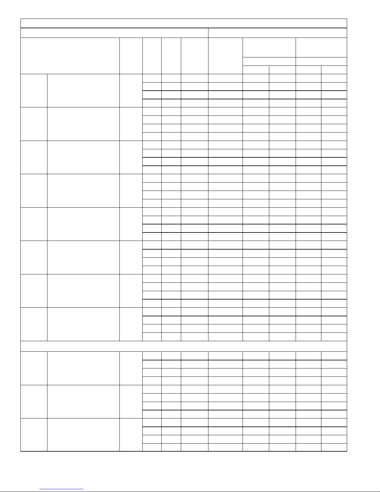
Specifications
General Data Model Number CBX32MV‐018/024 CBX32MV‐024/030 CBX32MV‐036
Nominal cooling capacity - tons (kW) 1.5 - 2 (5.3 - 7) 2 - 2.5 (7 - 8.8) 3 (10.6)
Refrigerant R-410A R-410A R-410A
Connections
in. (mm)
Indoor Coil
Blower Data
Wheel nominal diameter x width - in. (mm) 10 x 7 (279 x 178) 10 x 8 (279 x 203) 10 x 8 (279 x 203)
Filters
Shipping Data - 1 Package lbs. (kg) 126 (57) 152 (69) 183 (83)
ELECTRICAL DATA
Voltage - phase - 60hz 208/230V-1ph
Maximum overcurrent protection (unit only)
Suction (vapor) line - sweat 5/8 (15.8) 3/4 (19) 3/4 (19)
Liquid line - sweat 3/8 (9.5) 3/8 (9.5) 3/8 (9.5)
Condensate drain (fpt) (2) 3/4 (19) (2) 3/4 (19) (2) 3/4 (19)
Net face area - ft.2 (m2) 3.56 (0.33) 4.44 (0.41) 5.0 (0.46)
Tube outside diameter - in. (mm) 3/8 (9.5) 3/8 (9.5) 3/8 (9.5)
Number of rows 3 3 3
Fins per inch (fins per m) 12 (472) 12 (472) 12 (472)
Motor output - hp (W) 1/2 (373) 1/2 (373) 1/2 (373)
1
Number and size - in. (1) 15 x 20 x 1 (1) 20 x 20 x 1 (1) 20 x 20 x 1
mm 381 x 508 x 25 508 x 508 x 25 508 x 508 x 25
208/230V-1ph 208/230V-1ph
2
15 15 15
Minimum circuit ampacity (unit only) 5 5 5
General Data Model Number CBX32MV‐048 CBX32MV‐060 CBX32MV‐068
Nominal cooling capacity - tons (kW) 4 (14.1) 5 (17.6) 5+ (17.6+)
Refrigerant HFC-410A HFC-410A HFC-410A
Connections
in. (mm)
Suction (vapor) line - sweat 7/8 (22.2) 1‐1/8 (28) 1‐1/8 (28)
Liquid line - sweat 3/8 (9.5) 3/8 (9.5) 3/8 (9.5)
Condensate drain (fpt) (2) 3/4 (19) (2) 3/4 (19) (2) 3/4 (19)
Indoor Coil
Net face area - ft.2 (m2) 7.22 (0.67) 7.22 (0.67) 7.77 (0.72)
Tube outside diameter - in. (mm) 3/8 (9.5) 3/8 (9.5) 3/8 (9.5)
Number of rows 3 3 3
Fins per inch (fins per m) 12 (472) 12 (472) 12 (472)
Blower Data
Wheel nominal diameter x width - in. (mm) 12 x 9 (305 x 229) 12 x 9 (305 x 229) 15 x 9 (381 x 229)
Motor output - hp (W) 1 (746) 1 (746) 1 (746)
Filters
1
Number and size - in. (1) 20 x 24 x 1 (1) 20 x 24 x 1 (1) 20 x 25 x 1
mm 508 x 610 x 25 508 x 610 x 25 508 x 635 x 25
Shipping Data - 1 Package - lbs. (kg) 212 (96) 212 (96) 244 (111)
ELECTRICAL DATA
Voltage - phase - 60hz 208/230V-1ph
Maximum overcurrent protection (unit only)
2
20 20 20
208/230V-1ph 208/230V-1ph
Minimum circuit ampacity (unit only) 11 11 11
CBX32MV
Page 2
Page 3
Optional Accessories
For up-to-date information, see any of the following publications:
Lennox CBX32MV Product Specification bulletin (EHB)
Lennox Commercial Price Book
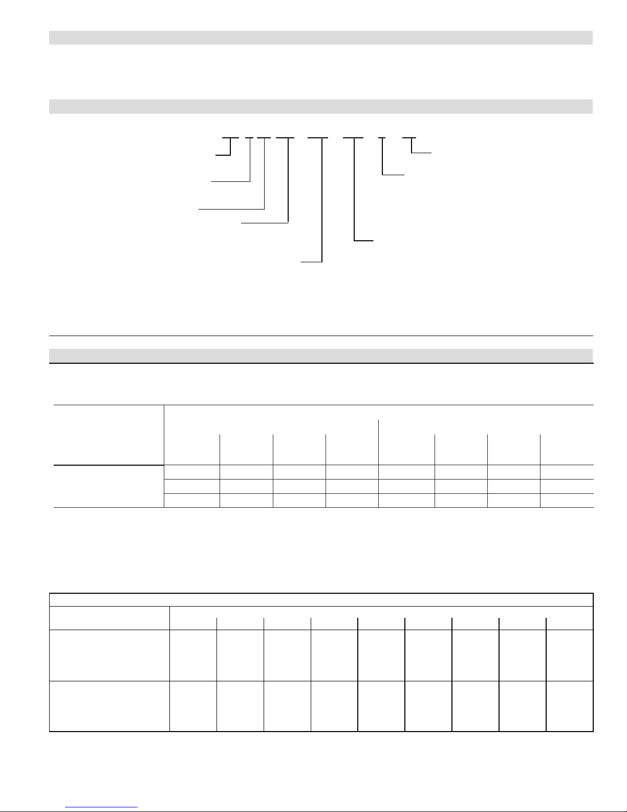
Model Identification
Unit Type
X
MV
−
−
230CB 32 036
−−
05
6
Minor Revision Number
CB = Air Handler
Refrigerant Type
X = R-410A
Series
Configuration
MV = Multi-Position, Variable
speed blower motor
Refrigerant Metering Device
2 = Fixed Orifice
3 = TXV - Bleedport (indoor unit)
4 = TXV - Non-bleedport (indoor unit)
5 = TXV - Non-bleedport (outdoor unit)
6 = TXV - R-410A Non-bleedport (indoor
unit)
Voltage
230 = 208/230V-60hz-1ph
Nominal Cooling Capacity
018/024 = 1.5 to 2 tons (5.3 to 7 kW)
024/030 = 2 to 2.5 tons (7 to 8.8 kW)
036 = 3 tons (10.6 kW)
048 = 4 tons (14.1 kW)
060 = 5 tons (17.6 kW)
068 = 5+ tons (17.6+ kW)
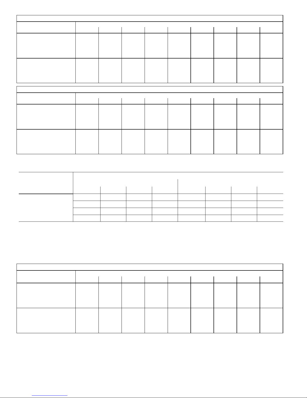
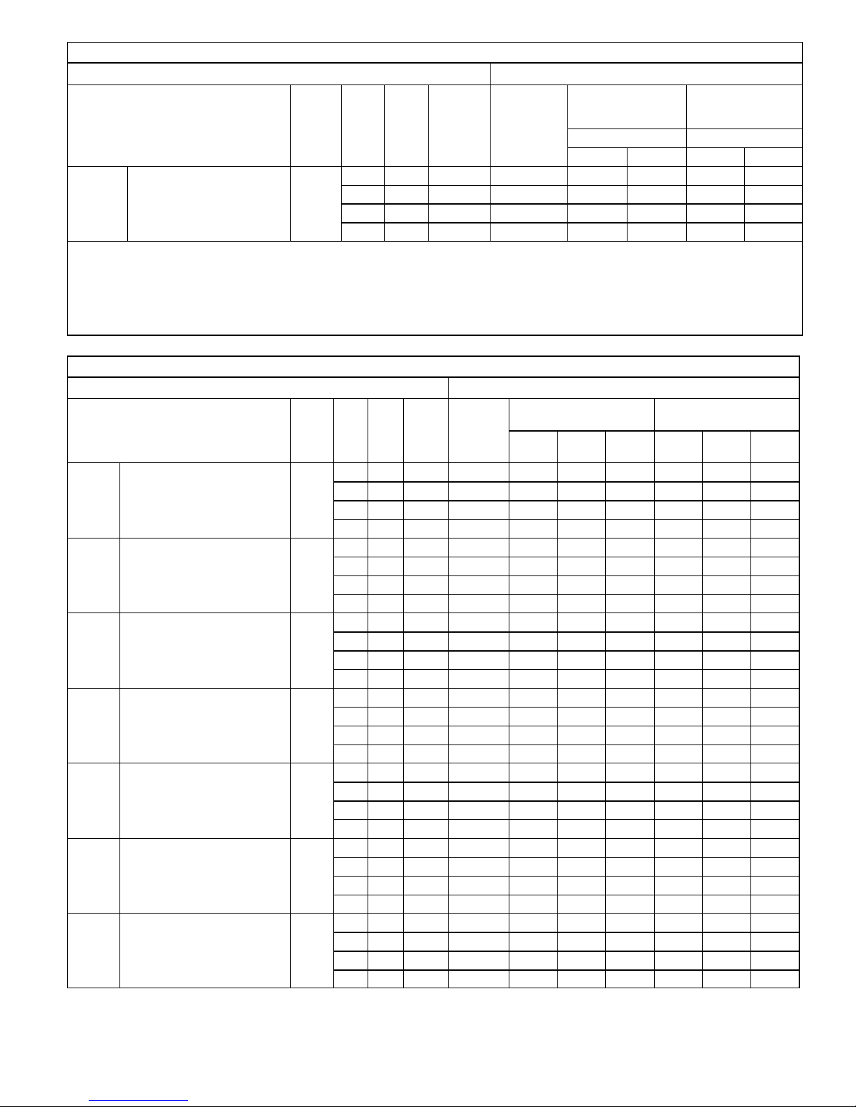
Blower Data
CBX32MV018/024 BLOWER PERFORMANCE
0 through 0.80 in. w.g. External Static Pressure Range
Jumper Speed Positions
“AJUST”
Jumper Setting
NORM
NOTES:
1
cfm
+
-
715 855 1000 1130 465 690 900 1050
670
580 700 800 930 385 560 735 850
“HEAT” Speed “COOL” Speed
2
cfm
770 900 1035 425 620 825 950
3
cfm
4
cfm
1
cfm
2
cfm
3
cfm
cfm
The effect of static pressure, filter and electric heater resistance is included in the air volumes listed.
First stage cooling air volume is 70% of COOL speed settings. Continuous fan speed is approximately 28%, 38%, 70% and 100% (Jumper
selectable) of the same secondstage COOL speed selected, minimum 250 cfm.
Lennox Harmony III™ Zone Control applications - minimum blower speed of 250 cfm.
4
CBX32MV‐018/024 BLOWER MOTOR WATTS AT + (Plus) SETTING (Adjust Jumper at + Setting)
Jumper Speed Positions
Tap 1 100 113 126 142 154 172 190 206 230
HEAT Speed
COOL Speed
Tap 2 155 176 197 221 237 260 278 295 310
Tap 3 237 260 289 305 314 337 356 373 390
Tap 4 338 361 379 409 433 457 447 426 406
Tap 1 36 47 61 71 81 95 106 11 8 135
Tap 2 89 103 118 129 143 163 177 197 207
Tap 3 183 198 229 248 266 290 307 327 343
Tap 4 266 294 315 330 349 373 390 411 401
0 (0) 0.1 (25) 0.2 (50) 0.3 (75) 0.4 (100) 0.5 (125) 0.6 (150) 0.7 (175) 0.8 (200)
Motor Watts @ Various External Static Pressures - in. wg. (Pa)
Page 3
CBX32MV
Page 4
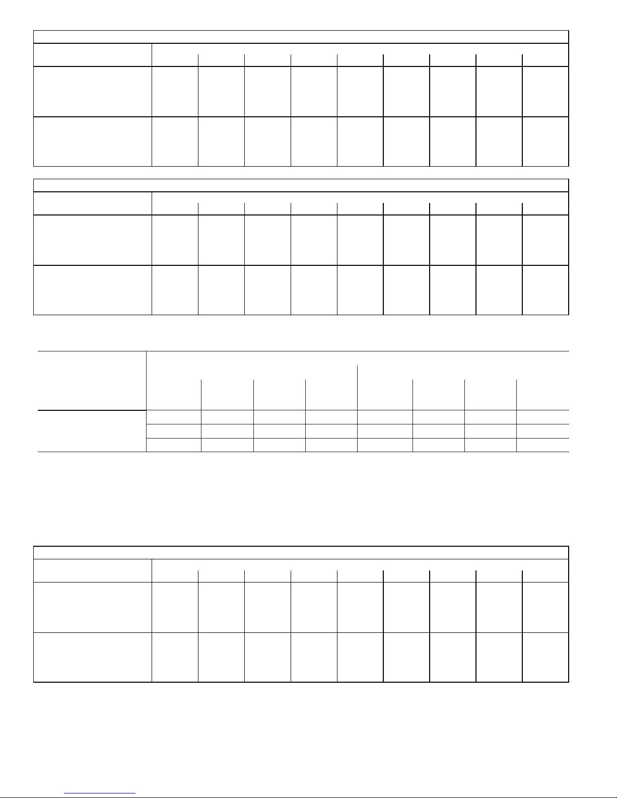
CBX32MV‐018/024 BLOWER MOTOR WATTS AT NORM SETTING
Jumper Speed Positions
Tap 1 77 96 106 123 130 150 165 178 201
HEAT Speed
COOL Speed
Tap 2 118 136 154 177 189 212 224 247 265
Tap 3 183 198 224 248 264 284 307 321 343
Tap 4 264 284 300 326 343 367 385 406 390
Tap 1 30 41 55 62 76 86 94 106 114
Tap 2 71 83 101 113 125 138 156 166 185
Tap 3 137 158 176 199 219 238 254 273 296
Tap 4 211 225 249 272 295 318 331 342 367
0 (0) 0.1 (25) 0.2 (50) 0.3 (75) 0.4 (100) 0.5 (125) 0.6 (150) 0.7 (175) 0.8 (200)
Motor Watts @ Various External Static Pressures - in. wg. (Pa)
(Adjust Jumper at NORM Setting)
CBX32MV‐018/024 BLOWER MOTOR WATTS AT - (Minus) SETTING (Adjust Jumper at - Setting)
Jumper Speed Positions
Tap 1 59 73 89 106 113 130 142 156 173
HEAT Speed
COOL Speed
Tap 2 95 106 118 136 152 171 183 200 215
Tap 3 132 148 171 186 211 225 248 266 284
Tap 4 195 217 242 259 283 302 314 336 349
Tap 1 27 35 47 59 71 77 88 92 106
Tap 2 57 65 83 94 110 119 134 148 166
Tap 3 110 124 141 157 176 188 213 231 242
Tap 4 148 170 195 207 230 248 272 282 306
0 (0) 0.1 (25) 0.2 (50) 0.3 (75) 0.4 (100) 0.5 (125) 0.6 (150) 0.7 (175) 0.8 (200)
Motor Watts @ Various External Static Pressures - in. wg. (Pa)
CBX32MV024/030 BLOWER PERFORMANCE
0 through 0.80 in. w.g. External Static Pressure Range
Jumper Speed Positions
“AJUST”
Jumper Setting
NORM
NOTES:
1
cfm
+
-
800 935 1070 1210 660 880 1100 1320
725
655 765 880 990 540 720 900 1080
“HEAT” Speed “COOL” Speed
2
cfm
850 975 1100 600 800 1000 1200
3
cfm
4
cfm
1
cfm
2
cfm
3
cfm
cfm
The effect of static pressure, filter and electric heater resistance is included in the air volumes listed.
First stage cooling air volume is 70% of COOL speed settings. Continuous fan speed is approximately 28%, 38%, 70% and 100% (Jumper
selectable) of the same secondstage COOL speed selected, minimum 250 cfm.
Lennox Harmony III™ Zone Control applications - minimum blower speed of 250 cfm.
CBX32MV‐024/030 BLOWER MOTOR WATTS AT + (Plus) SETTING (Adjust Jumper at + Setting)
Jumper Speed Positions
Tap 1 65 90 120 145 185 210 240 250 275
HEAT Speed
COOL Speed
Tap 2 95 125 150 185 230 265 310 345 365
Tap 3 140 190 225 250 290 320 350 405 450
Tap 4 215 250 285 315 350 390 440 480 505
Tap 1 45 60 90 120 140 155 165 185 200
Tap 2 80 110 135 165 205 250 285 315 335
Tap 3 150 195 225 260 295 320 370 425 465
Tap 4 265 315 350 400 440 485 525 555 605
0 (0) 0.1 (25) 0.2 (50) 0.3 (75) 0.4 (100) 0.5 (125) 0.6 (150) 0.7 (175) 0.8 (200)
Motor Watts @ Various External Static Pressures - in. wg. (Pa)
4
CBX32MV
Page 4
Page 5
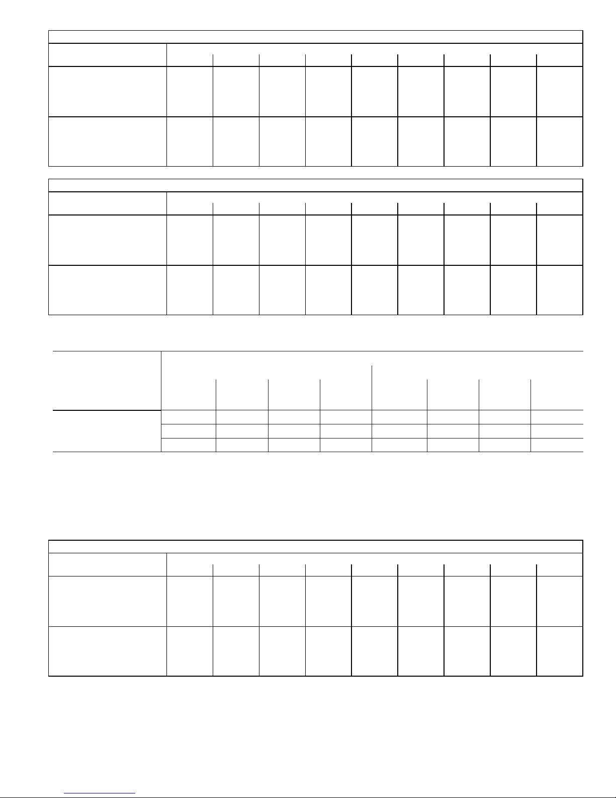
CBX32MV‐024/030 BLOWER MOTOR WATTS AT NORM SETTING
Jumper Speed Positions
Tap 1 50 75 100 135 155 180 195 215 230
HEAT Speed
COOL Speed
Tap 2 80 105 130 155 200 245 265 295 310
Tap 3 110 150 175 200 235 275 320 350 390
Tap 4 155 205 230 270 290 325 360 405 460
Tap 1 40 55 80 105 120 130 150 165 180
Tap 2 65 90 120 145 190 210 240 260 285
Tap 3 105 145 175 220 250 285 335 370 405
Tap 4 200 245 275 300 335 385 420 470 515
0 (0) 0.1 (25) 0.2 (50) 0.3 (75) 0.4 (100) 0.5 (125) 0.6 (150) 0.7 (175) 0.8 (200)
Motor Watts @ Various External Static Pressures - in. wg. (Pa)
(Adjust Jumper at NORM Setting)
CBX32MV‐024/030 BLOWER MOTOR WATTS AT - (Minus) SETTING (Adjust Jumper at - Setting)
Jumper Speed Positions
Tap 1 45 65 90 110 130 150 165 190 195
HEAT Speed
COOL Speed
Tap 2 60 85 110 145 175 200 215 235 240
Tap 3 85 105 130 165 210 245 280 305 330
Tap 4 115 145 175 205 230 280 325 370 390
Tap 1 30 50 70 90 100 115 125 140 165
Tap 2 55 75 100 135 155 185 190 210 225
Tap 3 85 115 135 175 210 255 295 320 345
Tap 4 145 175 215 245 280 325 355 410 450
0 (0) 0.1 (25) 0.2 (50) 0.3 (75) 0.4 (100) 0.5 (125) 0.6 (150) 0.7 (175) 0.8 (200)
Motor Watts @ Various External Static Pressures - in. wg. (Pa)
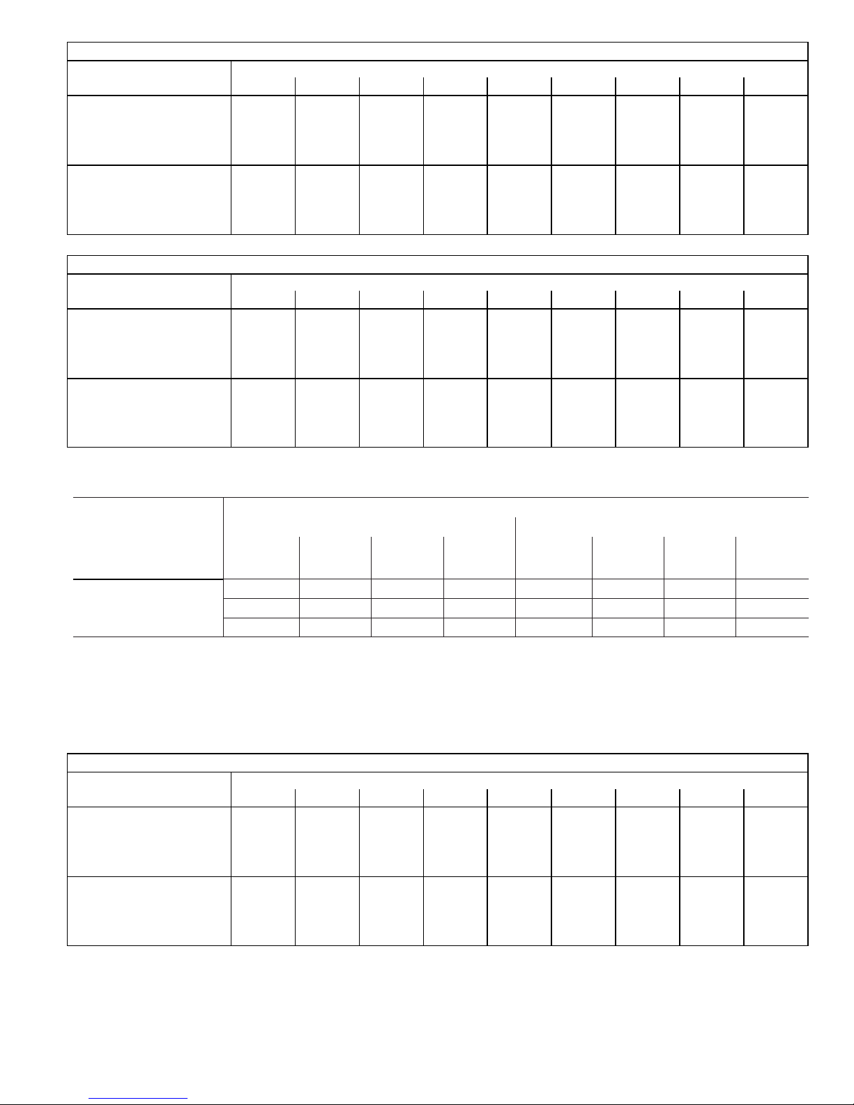
CBX32MV036 BLOWER PERFORMANCE
0 through 0.80 in. w.g. External Static Pressure Range
Jumper Speed Positions
“AJUST”
Jumper Setting
NORM
NOTES:
1
cfm
+
-
1230 1335 1445 1545 900 1225 1380 1545
1120
1010 1185 1200 1265 730 1000 1135 1265
“HEAT” Speed “COOL” Speed
2
cfm
1215 1315 1400 810 1125 1275 1400
3
cfm
4
cfm
1
cfm
2
cfm
3
cfm
cfm
The effect of static pressure, filter and electric heater resistance is included in the air volumes listed.
First stage cooling air volume is 70% of COOL speed settings. Continuous fan speed is approximately 28%, 38%, 70% and 100% (Jumper
selectable) of the same secondstage COOL speed selected, minimum 250 cfm.
Lennox Harmony III™ Zone Control applications - minimum blower speed of 250 cfm.
CBX32MV‐036 BLOWER MOTOR WATTS AT + (Plus) SETTING (Adjust Jumper at + Setting)
Jumper Speed Positions
Tap 1 220 235 265 290 310 335 360 385 465
HEAT Speed
COOL Speed
Tap 2 285 305 330 355 380 405 430 450 475
Tap 3 345 365 405 430 455 485 515 545 570
Tap 4 470 495 515 530 545 560 575 595 610
Tap 1 145 165 200 225 250 275 300 325 350
Tap 2 225 245 265 290 320 350 370 395 410
Tap 3 305 325 350 390 420 445 475 505 535
Tap 4 470 495 515 530 545 560 575 595 610
0 (0) 0.1 (25) 0.2 (50) 0.3 (75) 0.4 (100) 0.5 (125) 0.6 (150) 0.7 (175) 0.8 (200)
Motor Watts @ Various External Static Pressures - in. wg. (Pa)
4
Page 5
CBX32MV
Page 6
CBX32MV‐036 BLOWER MOTOR WATTS AT NORM SETTING
Jumper Speed Positions
Tap 1 155 185 215 240 265 285 300 335 355
HEAT Speed
COOL Speed
Tap 2 225 245 270 295 325 345 370 390 415
Tap 3 275 290 315 340 375 400 420 445 465
Tap 4 320 345 375 405 435 460 485 515 540
Tap 1 120 140 160 190 210 230 255 275 300
Tap 2 160 190 220 240 265 290 320 340 365
Tap 3 255 270 295 320 345 375 400 420 445
Tap 4 320 345 375 405 435 460 485 515 540
0 (0) 0.1 (25) 0.2 (50) 0.3 (75) 0.4 (100) 0.5 (125) 0.6 (150) 0.7 (175) 0.8 (200)
Motor Watts @ Various External Static Pressures - in. wg. (Pa)
(Adjust Jumper at NORM Setting)
CBX32MV‐036 BLOWER MOTOR WATTS AT - (Minus) SETTING (Adjust Jumper at - Setting)
Jumper Speed Positions
Tap 1 120 135 165 185 205 225 245 265 300
HEAT Speed
COOL Speed
Tap 2 140 165 195 215 245 270 300 315 335
Tap 3 185 210 240 265 285 310 330 360 385
Tap 4 245 255 290 310 335 355 380 405 430
Tap 1 90 110 135 155 180 195 210 230 250
Tap 2 120 140 160 185 215 235 255 275 295
Tap 3 160 190 225 240 275 295 320 350 380
Tap 4 245 255 290 310 335 355 380 405 430
0 (0) 0.1 (25) 0.2 (50) 0.3 (75) 0.4 (100) 0.5 (125) 0.6 (150) 0.7 (175) 0.8 (200)
Motor Watts @ Various External Static Pressures - in. wg. (Pa)
CBX32MV048 and CBX32MV060 BLOWER PERFORMANCE
0 through 0.80 in. w.g. External Static Pressure Range
Jumper Speed Positions
“AJUST”
Jumper Setting
NORM
NOTES:
1 2 3 4 1 2 3 4
+
-
cfm cfm cfm cfm cfm cfm cfm cfm
1850
1705
1560 1625 1720 1770 1205 1375 1555 1725
“HEAT” Speed “COOL” Speed
1960 2090 2150 1625 1820 2055 2145
1800 1900 2005 1425 1625 1805 2005
The effect of static pressure, filter and electric heater resistance is included in the air volumes listed.
First stage cooling air volume is 70% of COOL speed settings. Continuous fan speed is approximately 28%, 38%, 70% and 100% (Jumper
selectable) of the same secondstage COOL speed selected, minimum 450 cfm.
Lennox Harmony III™ Zone Control applications - minimum blower speed of 450 cfm.
CBX32MV‐048 AND CBX32MV‐060 BLOWER MOTOR WATTS AT + (Plus) SETTING (Adjust Jumper at + Setting)
Jumper Speed Positions
Tap 1 455 505 540 585 630 665 710 745 780
HEAT Speed
COOL Speed
Tap 2 555 595 645 675 730 780 820 865 895
Tap 3 680 720 770 820 865 900 945 985 1030
Tap 4 730 780 825 870 920 970 1020 1055 1110
Tap 1 300 335 370 360 435 465 500 535 575
Tap 2 425 475 500 545 585 635 670 710 745
Tap 3 625 660 705 755 810 850 885 940 970
Tap 4 700 750 800 845 895 940 990 1030 1080
0 (0) 0.1 (25) 0.2 (50) 0.3 (75) 0.4 (100) 0.5 (125) 0.6 (150) 0.7 (175) 0.8 (200)
Motor Watts @ Various External Static Pressures - in. wg. (Pa)
CBX32MV
Page 6
Page 7
CBX32MV‐048 AND CBX32MV‐060 BLOWER MOTOR WATTS AT NORM SETTING
Jumper Speed Positions
Tap 1 360 385 425 465 495 525 565 600 635
HEAT Speed
COOL Speed
Tap 2 400 440 485 520 555 595 640 670 705
Tap 3 480 520 560 605 640 685 765 785 805
Tap 4 580 625 665 710 760 800 835 875 925
Tap 1 215 235 275 295 330 360 400 430 465
Tap 2 310 335 375 405 440 465 500 530 565
Tap 3 415 445 490 535 565 605 650 675 715
Tap 4 580 610 655 695 740 785 830 870 910
0 (0) 0.1 (25) 0.2 (50) 0.3 (75) 0.4 (100) 0.5 (125) 0.6 (150) 0.7 (175) 0.8 (200)
Motor Watts @ Various External Static Pressures - in. wg. (Pa)
(Adjust Jumper at NORM Setting)
CBX32MV‐048 AND CBX32MV‐060 BLOWER MOTOR WATTS AT - (Minus) SETTING (Adjust Jumper at - Setting)
Jumper Speed Positions
Tap 1 265 305 340 370 410 440 460 505 540
HEAT Speed
COOL Speed
Tap 2 320 350 395 420 450 475 515 545 580
Tap 3 375 410 435 470 515 545 575 610 645
Tap 4 400 435 480 525 555 595 640 670 700
Tap 1 140 170 195 215 250 275 300 335 360
Tap 2 200 230 260 285 315 355 385 415 450
Tap 3 280 315 340 380 415 445 465 505 540
Tap 4 375 420 440 475 515 550 575 610 645
0 (0) 0.1 (25) 0.2 (50) 0.3 (75) 0.4 (100) 0.5 (125) 0.6 (150) 0.7 (175) 0.8 (200)
Motor Watts @ Various External Static Pressures - in. wg. (Pa)
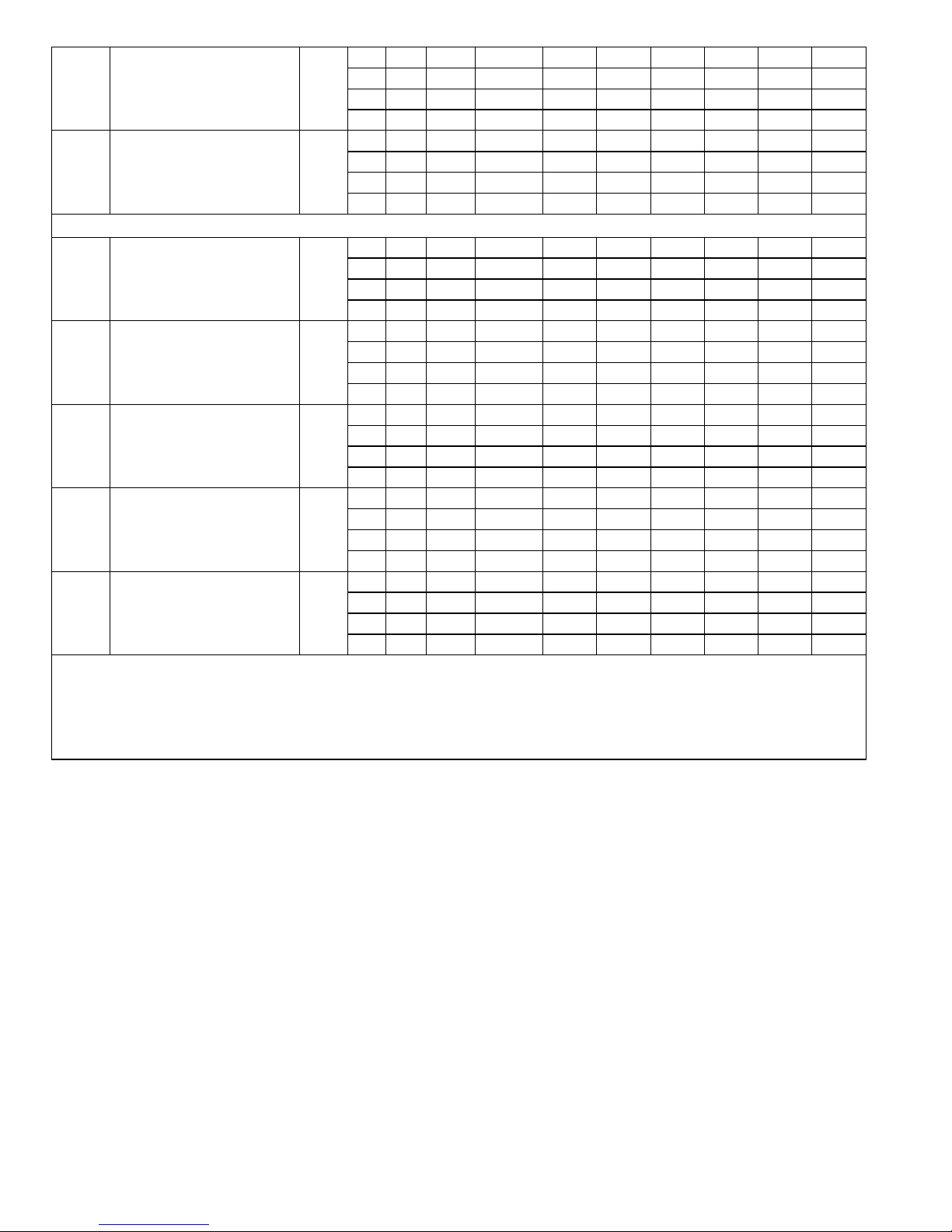
CBX32MV068 BLOWER PERFORMANCE
0 through 0.80 in. w.g. External Static Pressure Range
Jumper Speed Positions
“AJUST”
Jumper Setting
NORM
NOTES:
1
cfm
+
-
1875 1975 2090 2150 1640 1840 2075 2150
1760
1550 1650 1725 1800 1250 1390 1560 1720
“HEAT” Speed “COOL” Speed
2
cfm
1825 1920 2030 1465 1625 1800 2000
3
cfm
4
cfm
1
cfm
2
cfm
3
cfm
cfm
The effect of static pressure, filter and electric heater resistance is included in the air volumes listed.
First stage cooling air volume is 70% of COOL speed settings. Continuous fan speed is approximately 28%, 38%, 70% and 100% (Jumper
selectable) of the same secondstage COOL speed selected, minimum 450 cfm.
Lennox Harmony III™ Zone Control applications - minimum blower speed of 450 cfm.
CBX32MV‐068 BLOWER MOTOR WATTS AT + (Plus) SETTING (Adjust Jumper at + Setting)
Jumper Speed Positions
Tap 1 365 410 455 495 545 610 660 725 790
HEAT Speed
COOL Speed
Tap 2 430 485 540 590 640 690 765 835 865
Tap 3 540 585 635 695 750 800 815 840 865
Tap 4 665 710 755 770 790 810 830 845 870
Tap 1 255 290 320 365 415 455 505 550 590
Tap 2 355 390 425 475 515 580 630 695 750
Tap 3 505 565 610 70 715 790 815 845 865
Tap 4 725 745 755 770 790 810 830 850 870
0 (0) 0.1 (25) 0.2 (50) 0.3 (75) 0.4 (100) 0.5 (125) 0.6 (150) 0.7 (175) 0.8 (200)
Motor Watts @ Various External Static Pressures - in. wg. (Pa)
4
Page 7
CBX32MV
Page 8
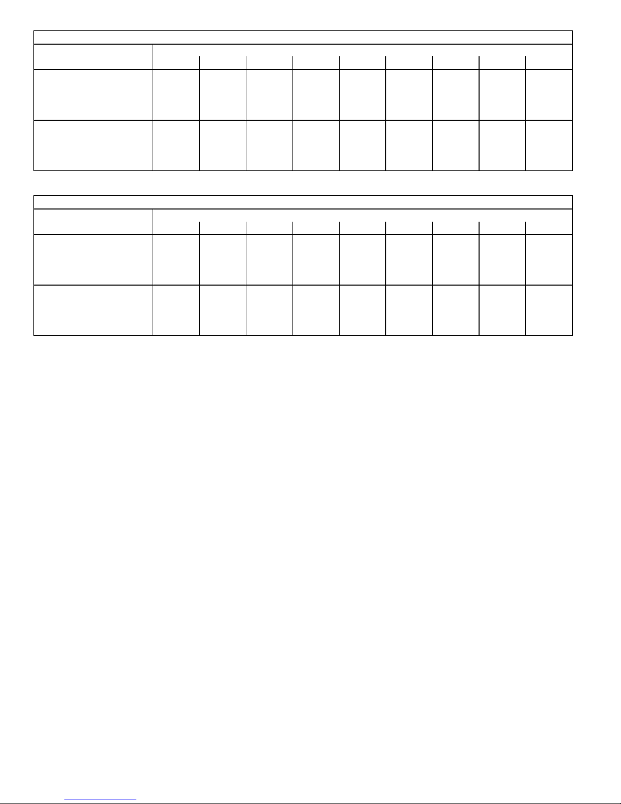
CBX32MV‐068 BLOWER MOTOR WATTS AT NORM SETTING (Adjust Jumper at NORM Setting)
Jumper Speed Positions
Tap 1 310 345 385 425 465 510 560 610 665
HEAT Speed
COOL Speed
Tap 2 345 385 420 460 500 620 615 680 735
Tap 3 385 430 480 525 580 640 695 750 815
Tap 4 475 525 560 615 660 720 785 845 810
Tap 1 180 205 240 285 325 365 405 435 480
Tap 2 250 285 320 355 410 455 505 535 585
Tap 3 345 375 415 460 505 560 610 670 735
Tap 4 445 510 560 595 665 725 790 845 865
0 (0) 0.1 (25) 0.2 (50) 0.3 (75) 0.4 (100) 0.5 (125) 0.6 (150) 0.7 (175) 0.8 (200)
Motor Watts @ Various External Static Pressures - in. wg. (Pa)
CBX32MV‐068 BLOWER MOTOR WATTS AT - (Minus) SETTING (Adjust Jumper at - Setting)
Jumper Speed Positions
Tap 1 215 245 285 325 375 415 460 495 540
HEAT Speed
COOL Speed
Tap 2 255 295 325 370 410 460 510 545 580
Tap 3 295 330 375 395 445 495 555 600 660
Tap 4 335 370 400 445 505 550 600 660 705
Tap 1 125 150 170 210 245 270 300 340 370
Tap 2 160 185 225 255 300 335 365 415 450
Tap 3 225 245 280 320 370 420 460 510 545
Tap 4 290 325 355 400 445 490 545 595 650
0 (0) 0.1 (25) 0.2 (50) 0.3 (75) 0.4 (100) 0.5 (125) 0.6 (150) 0.7 (175) 0.8 (200)
Motor Watts @ Various External Static Pressures - in. wg. (Pa)
CBX32MV
Page 8
Page 9
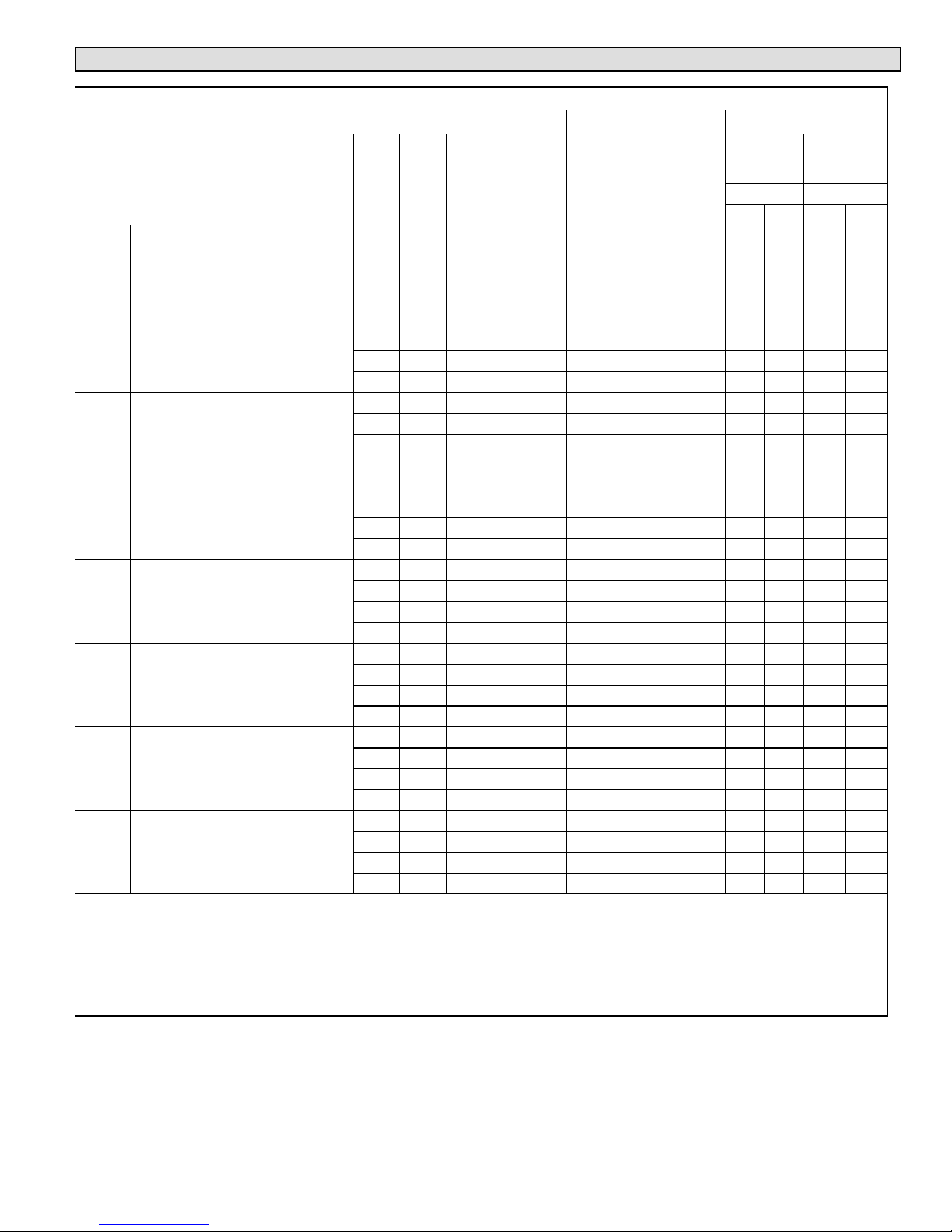
Electric Heat Data
ELECTRIC HEAT DATA - CBX32MV-018/024 AND CBX32MV-024/030
SINGLE PHASE ELECTRIC HEAT
2
1
Btuh
Input
2.5 kW
4 lbs.
Model Number
ECB40-2.5 (34W86)
Terminal Block
No. of
Stages
1
Volts
InputkWInput
208 1.9 6,400 4.0 16 20 - - - - - - - - - - - -
220 2.1 7,200 4.0 17 20 - - - - - - - - - - - -
230 2.3 7,800 4.0 18 20 - - - - - - - - - - - -
240 2.5 8,500 4.0 18 20 - - - - - - - - - - - -
4 kW
4 lbs.
ECB40-4 (55W89)
Terminal Block
ECB40-4CB (55W90)
30A Circuit breaker
1
208 3.0 10,250 4.0 23 25 23 - - - 25 - - -
220 3.4 11,450 4.0 24 25 24 - - - 25 - - -
230 3.7 12,550 4.0 25 25 25 - - - 25 - - -
240 4.0 13,650 4.0 26 30 26 - - - 30 - - -
5 kW
4 lbs.
ECB40-5 (34W87)
Terminal Block
ECB40-5CB (34W90)
35A Circuit breaker
1
208 3.8 12,800 4.0 28 30 28 - - - 30 - - -
220 4.2 14,300 4.0 29 30 29 - - - 30 - - -
230 4.6 15,700 4.0 30 30 30 - - - 30 - - -
240 5.0 17,100 4.0 31 35 31 - - - 35 - - -
6 kW
4 lbs.
ECB40-6 (34W88)
Terminal Block
ECB40-6CB (34W91)
40A Circuit breaker
1
208 4.5 15,400 4.0 32 35 32 - - - 35 - - -
220 5.0 17,100 4.0 33 35 33 - - - 35 - - -
230 5.5 18,800 4.0 35 35 35 - - - 35 - - -
240 6.0 20,500 4.0 36 40 36 - - - 40 - - -
8 kW
5 lbs.
ECB40-8 (34W89)
Terminal Block
ECB40-8CB (34W92)
50A Circuit breaker
1
208 6.0 20,500 4.0 41 45 41 - - - 45 - - -
220 6.7 22,900 4.0 43 45 43 - - - 45 - - -
230 7.3 25,100 4.0 45 45 45 - - - 45 - - -
240 8.0 27,300 4.0 47 50 47 - - - 50 - - -
9 kW
5 lbs.
ECB40-9CB (34W93)
60A Circuit breaker
2
208 6.8 23,100 4.0 - - - - - - 46 - - - 50 - - -
220 7.6 25,800 4.0 - - - - - - 48 - - - 50 - - -
230 8.3 28,200 4.0 - - - - - - 50 - - - 50 - - -
240 9.0 30,700 4.0 - - - - - - 52 - - - 60 - - -
12.5
kW
10 lbs.
ECB40-12.5CB (34W94)
(1) 30A & (1) 45A Circuit
breaker
2
208 9.4 32,000 4.0 - - - - - - 24 38 25 40
220 10.5 35,800 4.0 - - - - - - 25 40 25 40
230 11.5 39,200 4.0 - - - - - - 26 42 30 45
240 12.5 42,600 4.0 - - - - - - 27 44 30 45
15 kW
12 lbs.
ECB40-15CB (34W95)
(1) 35A & (1) 60A Circuit
breaker
2
208 11.3 38,400 4.0 - - - - - - 28 45 30 45
220 12.6 43,000 4.0 - - - - - - 29 48 30 50
230 13.8 47,000 4.0 - - - - - - 30 50 30 50
240 15.0 51,200 4.0 - - - - - - 31 52 35 60
NOTE − Circuit 1 Minimum Circuit Ampacity includes the Blower Motor Full Load Amps.
1
Electric heater capacity only − does not include additional blower motor heat capacity.
2
Amps shown are for blower motor only.
3
Refer to National or Canadian Electrical Code manual to determine wire, fuse and disconnect size requirements. Use wires suitable for at least
167F.
4
Bold text indicates that the circuit breaker on “CB” circuit breaker models must be replaced with size noted. See Table on page 6.
5
HACR type circuit breaker or fuse.
Blower
Motor
Full Load
Amps
CBX32MV-018/024 CBX32MV-024/030
3
Minimum
Circuit
Ampacity
5
Maximum
Overcurrent
Protection
3
Minimum
Circuit
Ampacity
Circuit Circuit
5
Overcurrent
1 2 1 2
Maximum
Protection
Page 9
CBX32MV
Page 10
ELECTRIC HEAT DATA - CBX32MV-036
SINGLE PHASE ELECTRIC HEAT
No. of
Stages
1
1
1
1
2
2
2
2
4 kW
4 lbs.
5 kW
4 lbs.
6 kW
4 lbs.
8 kW
5 lbs.
9 kW
5 lbs.
12.5 kW
10 lbs.
15 kW
12 lbs.
20 kW
19 lbs.
Model Number
ECB40−4 (55W89)
Terminal Block
ECB40−4CB (55W90)
35A Circuit breaker
ECB40−5 (34W87)
Terminal Block
ECB40−5CB (34W90)
35A Circuit breaker
ECB40−6 (34W88)
Terminal Block
ECB40−6CB (34W91)
40A Circuit breaker
ECB40−8 (34W89)
Terminal Block
ECB40−8CB (34W92)
50A Circuit breaker
ECB40−9CB (34W93)
60A Circuit breaker
ECB40−12.5CB (34W94)
(1) 30A & (1) 45A Circuit
breaker
ECB40−15CB (34W95)
(1) 35A & (1) 60A Circuit
breaker
ECB40−20CB (34W96)
(2) 60A Circuit breaker
THREE PHASE ELECTRIC HEAT
8 kW
5 lbs.
10 kW
6 lbs.
15 kW
12 lbs.
ECB40−8 (34W98)
Terminal Block
ECB40−10 (34W99)
Terminal Block
ECB40−15CB (35W00)
50A Circuit breaker
1
1
1
CBX32MV-036
5
Maximum
Overcurrent
Protection
Volts
InputkWInput
1
Btuh In
put
2
Blower Mo
tor Full Load
Amps
3
Minimum Circuit
Ampacity
Circuit Circuit
1 2 1 2
208 3.0 10,250 4.0 23 - - - 25 - - -
220 3.4 11,450 4.0 24 - - - 25 - - -
230 3.7 12,550 4.0 25 - - - 25 - - -
240 4.0 13,650 4.0 26 - - - 30 - - -
208 3.8 12,800 4.0 28 - - - 30 - - -
220 4.2 14,300 4.0 29 - - - 30 - - -
230 4.6 15,700 4.0 30 - - - 30 - - -
240 5.0 17,100 4.0 31 - - - 35 - - -
208 4.5 15,400 4.0 32 - - - 35 - - -
220 5.0 17,100 4.0 33 - - - 35 - - -
230 5.5 18,800 4.0 35 - - - 35 - - -
240 6.0 20,500 4.0 36 - - - 40 - - -
208 6.0 20,500 4.0 41 - - - 45 - - -
220 6.7 22,900 4.0 43 - - - 45 - - -
230 7.3 25,100 4.0 45 - - - 45 - - -
240 8.0 27,300 4.0 47 - - - 50 - - -
208 6.8 23,100 4.0 46 - - - 50 - - -
220 7.6 25,800 4.0 48 - - - 50 - - -
230 8.3 28,200 4.0 50 - - - 50 - - -
240 9.0 30,700 4.0 52 - - - 60 - - -
208 9.4 32,000 4.0 24 38 25 40
220 10.5 35,800 4.0 25 40 25 40
230 11.5 39,200 4.0 26 42 30 45
240 12.5 42,600 4.0 27 44 30 45
208 11.3 38,400 4.0 28 45 30 45
220 12.6 43,000 4.0 29 48 30 50
230 13.8 47,000 4.0 30 50 30 50
240 15.0 51,200 4.0 31 52 35 60
208 15.0 51,200 4.0 46 50 50 50
220 16.8 57,300 4.0 48 53 50 60
230 18.4 62,700 4.0 50 55 50 60
240 20.0 68,200 4.0 52 57 60 60
208 6.0 20,500 4.0 26 - - - 30 - - -
220 6.7 22,900 4.0 27 - - - 30 - - -
230 7.3 25,100 4.0 28 - - - 30 - - -
240 8.0 27,300 4.0 28 - - - 30 - - -
208 7.5 25,600 4.0 31 - - - 35 - - -
220 8.4 28,700 4.0 33 - - - 35 - - -
230 9.2 31,400 4.0 34 - - - 35 - - -
240 10.0 34,100 4.0 35 - - - 35 - - -
208 11.3 38,400 4.0 44 - - - 45 - - -
220 12.6 43,000 4.0 46 - - - 50 - - -
230 13.5 47,000 4.0 48 - - - 50 - - -
240 15.0 51,200 4.0 50 - - - 50 - - -
CBX32MV
Page 10
Page 11
ELECTRIC HEAT DATA - CBX32MV-036 (Continued)
THREE PHASE ELECTRIC HEAT
2
Blower Mo
tor Full Load
Amps
put
1
Btuh In
put
20 kW
19 lbs.
Model Number
ECB40−20CB (35W01)
(2) 35A Circuit breaker
No. of
Stages
2
Volts
kW In
Input
208 15.0 51,200 4.0 31 26 35 30
220 16.8 57,300 4.0 33 28 35 30
230 18.4 62,700 4.0 34 29 35 30
240 20.0 68,200 4.0 35 30 35 35
NOTE - Circuit 1 Minimum Circuit Ampacity includes the Blower Motor Full Load Amps.
1
Electric heater capacity only − does not include additional blower motor heat capacity.
2
Amps shown are for blower motor only.
3
Refer to National or Canadian Electrical Code manual to determine wire, fuse and disconnect size requirements. Use wires suitable for at least
167F.
4
Bold text indicates that the circuit breaker on “CB” circuit breaker models must be replaced with size noted. See Table on page 6.
5
HACR type circuit breaker or fuse.
CBX32MV-036
5
3
Minimum Circuit
Ampacity
Maximum
Overcurrent
Protection
Circuit Circuit
1 2 1 2
ELECTRIC HEAT DATA - CBX32MV-048, CBX32MV-060, AND CBX32MV-068
SINGLE PHASE ELECTRIC HEAT
Model Number
4 kW
4 lbs.
5 kW
4 lbs.
6 kW
4 lbs.
8 kW
5 lbs.
9 kW
5 lbs.
12.5 kW
10 lbs.
15 kW
12 lbs.
ECB40-4 (55W89)
Terminal Block
ECB40-4CB (55W90)
35A Circuit breaker
ECB40-5 (34W87)
Terminal Block
ECB40-5CB (34W90)
35A Circuit breaker
ECB40-6 (34W88)
Terminal Block
ECB40-6CB (34W91)
40A Circuit breaker
ECB40-8 (34W89)
Terminal Block
ECB40-8CB (34W92)
50A Circuit breaker
ECB40-9CB (34W93)
60A Circuit breaker
ECB40-12.5CB (34W94)
(1) 30A & (1) 45A Circuit
breaker
ECB40-15CB (34W95)
(1) 35A & (1) 60A Circuit
breaker
No. of
Stage
s
1
1
1
1
2
2
2
Volts
InputkWInput
1
Btuh
Input
208 3.0 10,250 7.4 27 - - - - - - 30 - - - - - -
220 3.4 11,450 7.4 28 - - - - - - 30 - - - - - -
230 3.7 12,550 7.4 29 - - - - - - 30 - - - - - -
240 4.0 13,650 7.4 30 - - - - - - 30 - - - - - -
208 3.8 12,800 7.4 32 - - - - - - 35 - - - - - -
220 4.2 14,300 7.4 33 - - - - - - 35 - - - - - -
230 4.6 15,700 7.4 34 - - - - - - 35 - - - - - -
240 5.0 17,100 7.4 35 - - - - - - 35 - - - - - -
208 4.5 15,400 7.4 36 - - - - - - 40 - - - - - -
220 5.0 17,100 7.4 38 - - - - - - 40 - - - - - -
230 5.5 18,800 7.4 39 - - - - - - 40 - - - - - -
240 6.0 20,500 7.4 41 - - - - - - 45 - - - - - -
208 6.0 20,500 7.4 45 - - - - - - 45 - - - - - -
220 6.7 22,900 7.4 47 - - - - - - 50 - - - - - -
230 7.3 25,100 7.4 49 - - - - - - 50 - - - - - -
240 8.0 27,300 7.4 51 - - - - - - 60 - - - - - -
208 6.8 23,100 7.4 50 - - - - - - 50 - - - - - -
220 7.6 25,800 7.4 52 - - - - - - 60 - - - - - -
230 8.3 28,200 7.4 54 - - - - - - 60 - - - - - -
240 9.0 30,700 7.4 56 - - - - - - 60 - - - - - -
208 9.4 32,000 7.4 28 38 - - - 30 40 - - -
220 10.5 35,800 7.4 29 40 - - - 30 40 - - -
230 11.5 39,200 7.4 30 42 - - - 30 45 - - -
240 12.5 42,600 7.4 31 44 - - - 35 45 - - -
208 11.3 38,400 7.4 32 45 - - - 35 45 - - -
220 12.6 43,000 7.4 33 48 - - - 35 50 - - -
230 13.5 47,000 7.4 34 50 - - - 35 50 - - -
240 15.0 51,200 7.4 35 52 - - - 35 60 - - -
CBX32MV-048, CBX32MV-060, AND CBX32MV-068
2
Blower
Motor Full
Load
Amps
3
Minimum Circuit Ampacity
Circuit1Circuit2Circuit3Circuit1Circuit2Circuit
5
Maximum Overcurrent
Protection
3
Page 11
CBX32MV
Page 12
20 kW
19 lbs.
ECB40-20CB (34W96)
(2) 60A Circuit breaker
2
208 15.0 51,200 7.4 50 50 - - - 50 50 - - -
220 16.8 57,300 7.4 52 53 - - - 60 60 - - -
230 18.4 62,700 7.4 54 55 - - - 60 60 - - -
240 20.0 68,200 7.4 56 57 - - - 60 60 - - -
25 kW
19 lbs.
ECB40-25CB (34W97)
(1) 60A & (2) 45A Circuit
breaker
3
208 18.8 64,100 7.4 47 38 38 50 40 40
220 21.0 71,700 7.4 49 40 40 50 40 40
230 23.0 78,300 7.4 51 42 42 60 45 45
240 25.0 85,300 7.4 53 44 44 60 45 45
THREE PHASE ELECTRIC HEAT
8 kW
5 lbs.
10 kW
6 lbs.
15 kW
12 lbs.
20 kW
19 lbs.
25 kW
19 lbs.
NOTE - Circuit 1 Minimum Circuit Ampacity includes the Blower Motor Full Load Amps.
1
Electric heater capacity only − does not include additional blower motor heat capacity.
2
Amps shown are for blower motor only.
3
Refer to National or Canadian Electrical Code manual to determine wire, fuse and disconnect size requirements. Use wires suitable for at least
167F.
4
Bold text indicates that the circuit breaker on “CB” circuit breaker models must be replaced with size noted. See Table on page 6.
5
HACR type circuit breaker or fuse.
ECB40-8 (34W98)
Terminal block
ECB40-10 (34W99)
Terminal block
ECB40-15CB (35W00)
50A Circuit breaker
ECB40-20CB (35W01)
(2) 35A Circuit breaker
ECB40-25CB (35W02)
(1) 50A & (1) 40A Circuit
breaker
1
208 6.0 20,500 7.4 30 - - - - - - 35 - - - - - -
220 6.7 22,900 7.4 31 - - - - - - 35 - - - - - -
230 7.3 25,100 7.4 32 - - - - - - 35 - - - - - -
240 8.0 27,300 7.4 33 - - - - - - 35 - - - - - -
1
208 7.5 25,600 7.4 35 - - - - - - 40 - - - - - -
220 8.4 28,700 7.4 37 - - - - - - 40 - - - - - -
230 9.2 31,400 7.4 38 - - - - - - 40 - - - - - -
240 10.0 34,100 7.4 39 - - - - - - 40 - - - - - -
1
208 11.3 38,400 7.4 48 - - - - - - 50 - - - - - -
220 12.6 43,000 7.4 51 - - - - - - 60 - - - - - -
230 13.5 47,000 7.4 52 - - - - - - 60 - - - - - -
240 15.0 51,200 7.4 54 - - - - - - 60 - - - - - -
2
208 15.0 51,200 7.4 35 26 - - - 40 30 - - -
220 16.8 57,300 7.4 37 28 - - - 40 30 - - -
230 18.4 62,700 7.4 38 29 - - - 40 30 - - -
240 20.0 68,200 7.4 39 30 - - - 40 35 - - -
2
208 18.8 64,100 7.4 42 33 - - - 45 35 - - -
220 21.0 71,700 7.4 44 34 - - - 45 35 - - -
230 23.0 78,300 7.4 45 36 - - - 50 40 - - -
240 25.0 85,300 7.4 47 38 - - - 50 40 - - -
CBX32MV
Page 12
Page 13
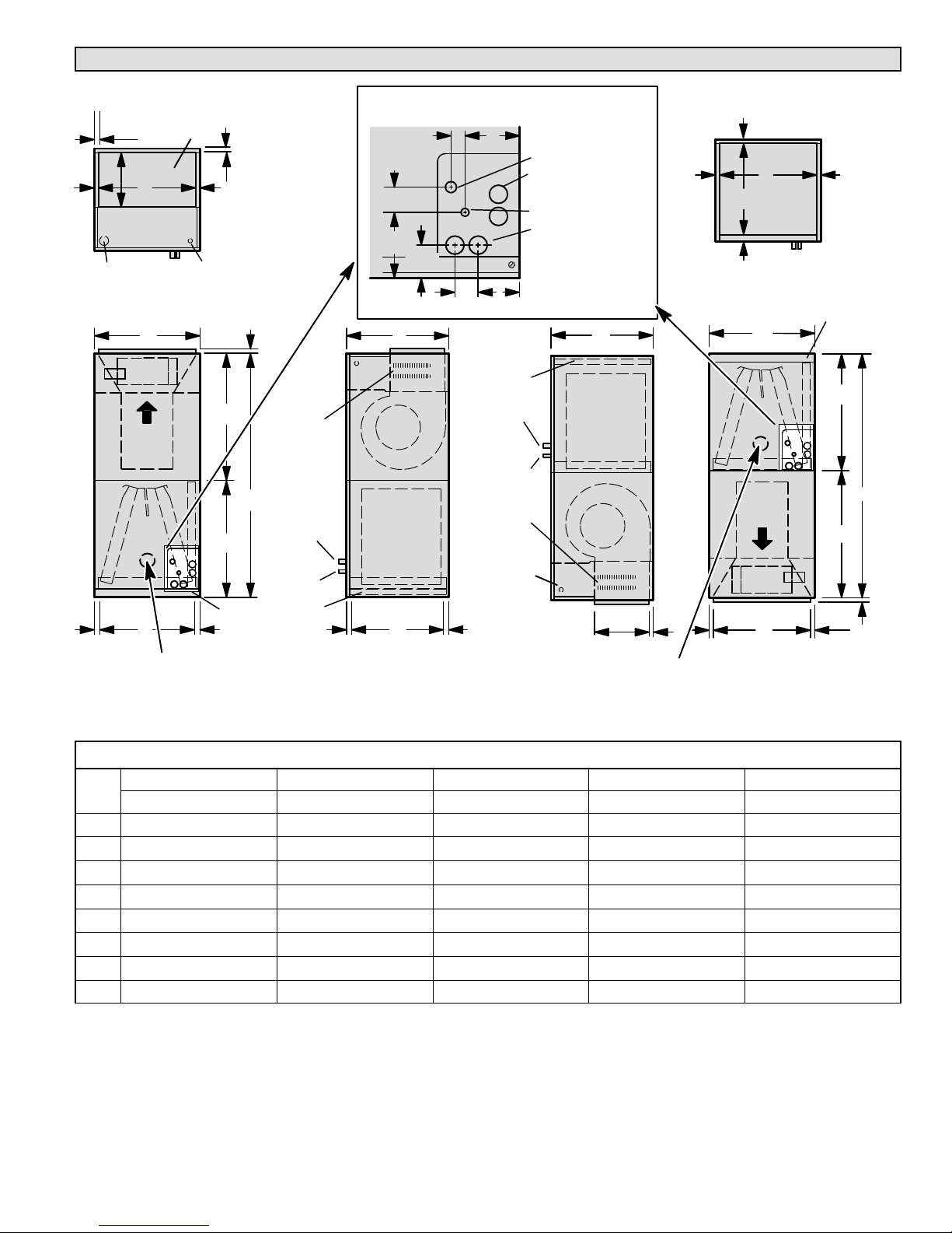
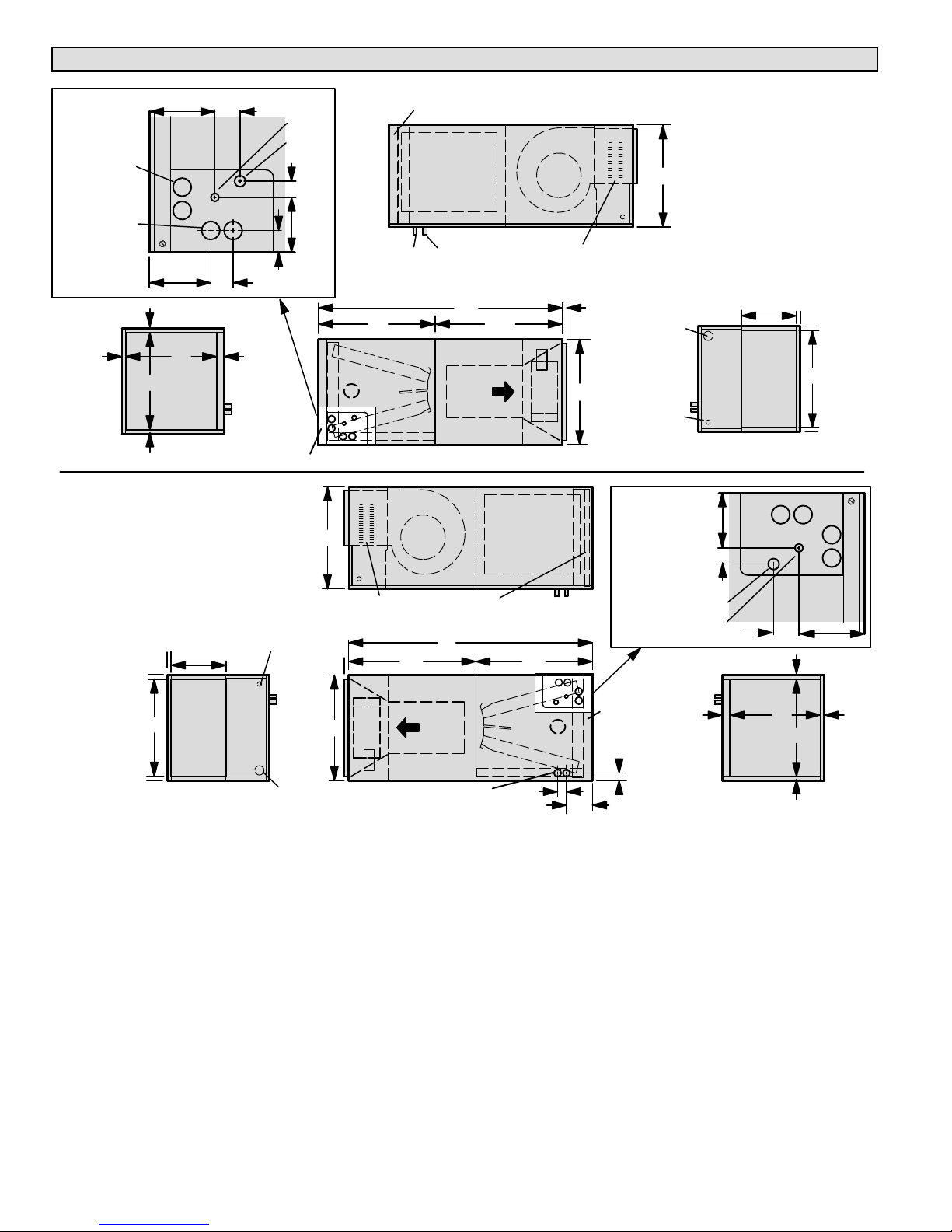
CBX32MV Upflow and Downflow Unit Dimensions — Inches (millimeters)
3/4 (19)
SUPPLY AIR
OPENING
D
11‐1/16 (281)
LINE VOLTAGE
INLETS (TOP
AND LEFT SIDE)
TOP VIEW
3/4 (19)
LOW VOLTAGE
INLETS (TOP AND
RIGHT SIDE)
5/8 (16)
BC
AIR
FLOW
G
OPTIONAL
ELECTRIC HEAT
(FIELD-INSTALLED)
A
SUCTION
H
RETURN AIR
5/8 (16) 1 (25)
KNOCKOUT FOR OPTIONAL HEALTHY
F
®
CLIMATE
GERMICIDAL UVC LIGHT.
FRONT VIEW
FILTER ACCESS
5/8 (16)
UPFLOW POSITION
LINE
LIQUID
LINE
FILTER
(FOR UPFLOW AND DOWNFLOW POSITIONS)
1‐1/8 (29)
2
(51)
5‐3/8
(137)
BLOWER
COIL
RETURN AIR
SIDE VIEW
PIPING PLATE DETAIL
2‐3/4
(70)
E
5/8 (16)
1‐3/4 (44)
FILTER
SUCTION
LINE
LIQUID
LINE
OPTIONAL
ELECTRIC HEAT
(FIELD-INSTALLED)
LOW VOLTAGE
(RIGHT SIDE)
LINE VOLTAGE
(LEFT SIDE)
4‐3/8 (111)
SUCTION LINE
CONDENSATE DRAINS
(2) (HORIZONTAL)
LIQUID LINE
CONDENSATE DRAINS
(2) (UPFLOW AND
DOWNFLOW)
3‐1/2 (89)
11‐1/16 (281)
5/8 (16)
C
COIL
BLOWER
SUPPLY
AIR
5/8 (16)
KNOCKOUT FOR OPTIONAL HEALTHY
®
CLIMATE
SIDE VIEW
DOWNFLOW POSITION
5/8 (16)
GERMICIDAL UVC LIGHT.
5/8 (16)
F
RETURN
E
OPENING
1 (25)
TOP VIEW
B
AIR FLOW
SUPPLY AIR
D
FRONT VIEW
5/8 (16)
AIR
FILTER ACCESS
H
A
G
5/8 (16)
CBX32MV Model Dimensions (Upflow, Downflow, Left- and Right-Hand Horizontal applications)
Dim.
A
B
C
D
E
F
G
H
-018/024 -024/030 -036 -048 and -060 -068
in. (mm) in. (mm) in. (mm) in. (mm) in. (mm)
45-1/4 (1149) 49-1/4 (1251) 51 (1295) 58‐1/2 (1486) 65 (1651)
16-1/4 (413) 21-1/4 (540) 21‐1/4 (540) 21‐1/4 (540) 21-1/4 (540)
20-5/8 (524) 20-5/8 (524) 22‐5/8 (575) 24‐5/8 (625) 26-5/8 (676)
14-3/4 (375) 19-3/4 (502) 19‐3/4 (502) 19‐3/4 (502) 19-3/4 (502)
19 (483) 19 (483) 21 (533) 23 (584) 25 (635)
15 (381) 20 (508) 20 (508) 20 (508) 20 (508)
24-5/8 (625) 24-5/8 (625) 26‐3/8 (670) 27‐7/8 (708) 32-3/8 (822)
20-5/8 (524) 24-5/8 (625) 24‐5/8 (625) 30‐5/8 (778) 32-5/8 (829)
Page 13
CBX32MV
Page 14
CBX32MV Horizontal Left- and Right-Hand Unit Dimensions — Inches (mm)
5‐3/8
(137)
CONDENSATE
DRAINS (2)
(UPFLOW AND
DOWNFLOW)
CONDENSATE
DRAINS (2)
(HORIZONTAL)
PIPING PLATE
DETAIL
5/8 (16)
5/8 (16)
5/8 (16)
5‐3/4
(46)
E
RETURN AIR
OPENING
F
END VIEW
Horizontal Position
(Left‐Hand Air
Discharge)
1‐3/4
(44)
(51)
2
LIQUID
1‐1/2
(38)
1 (25)
FILTER ACCESS
LINE
SUCTION
LINE
1‐1/8
(29)
4‐3/8
(111)
FILTER
Horizontal Position
(Right‐Hand Air
Discharge)
COIL
LIQUID
SUCTION
LINE
LINE
TOP VIEW
A
H
AIR
FLOW
FRONT VIEW
C
BLOWER
BLOWER
OPTIONAL ELECTRIC
HEAT (FIELD-INSTALLED)
G
COIL
5/8 (16)
B
C
LINE VOLTAGE
INLETS (TOP
AND RIGHT
SIDE)
LOW VOLTAGE
INLETS
(BOTTOM AND
RIGHT SIDE)
FOR DIMENSIONS “A”
THROUGH “H”, SEE CHART ON
4‐3/8
(111)
1‐1/8
(29)
PAGE 13.
11‐1/16
(281)
SUPPLY
AIR
OPENING
END VIEW
3/4 (19)
3/4 (19)
D
3/4 (19)
3/4 (19)
3/4 (19)
3/4 (19)
11‐1/16
(281)
SUPPLY
D
OPENING
LINE VOLTAGE INLETS
(BOTTOM AND LEFT SIDE)
END VIEW
INLETS (TOP AND
AIR
LOW VOLTAGE
LEFT SIDE)
OPTIONAL ELECTRIC
HEAT (FIELD INSTALLED)
5/8 (16)
B
CONDENSATE DRAINS (2)
(HORIZONTAL)
G
TOP VIEW
A
AIR
FLOW
FRONT VIEW
FILTER
SUCTION
LINE
H
1‐3/4
(44)
LIQUID
LINE
5‐3/4
(146)
SUCTION LINE
PIPING PLATE
DETAIL
FILTER ACCESS
1‐1/2 (38)
LIQUID
LINE
1 (25)
(51)
E
RETURN
AIR OPENING
END VIEW
2
5‐3/8
(137)
5/8 (16)
5/8 (16)
F
5/8 (16)
CBX32MV
Page 14
Page 15
General
This indoor unit is designed for installation with optional
field-installed electric heat and a matched remote outdoor
unit that is charged with HFC-410A refrigerant. These units,
designed for indoor installation in multiple positions, are
completely assembled for upflow and horizontal right-hand
discharge before being shipped from the factory.
All CBX32MV air handlers are equipped with a
factory-installed, internally mounted check expansion
valve (CTXV), which is suitable for use in HFC-410A
applications.
NOTE - For downflow or horizontal left-hand air discharge,
certain field modifications are required.
These instructions are intended as a general guide and do
not supersede local or national codes in any way. Consult
authorities having jurisdiction before installation. Check
equipment for shipping damage; if found, immediately
report damage to the last carrier.
Installation Clearances
Cabinet 0 inch (0 mm)
To Plenum 1 inch (25 mm)
To Outlet Duct within 3 feet (914
mm)
Floor See Note #1
Service / Maintenance See Note #2
1
Units installed on combustible floors in the down-flow position with
electric heat require optional down-flow additive base.
2 Front Service Access - 24 inches (610mm) minimum.
NOTE - If cabinet depth is more than 24 inches (610 mm), allow a
minimum of the cabinet depth plus 2 inches (51 mm).
1 inch (25 mm)
WARNING
The State of California has determined that this product
may contain or produce a chemical or chemicals, in very
low doses, which may cause serious illness or death. It
may also cause cancer, birth defects, or reproductive
harm.
IMPORTANT
The Clean Air Act of 1990 bans the intentional venting of
refrigerant (CFCs, HCFCs and HFCs) as of July 1, 1992.
Approved methods of recovery, recycling or reclaiming
must be followed. Fines and/or incarceration may be
levied for noncompliance.
WARNING
During blower operation, the ECM motor emits energy
that may interfere with pacemaker operation.
Interference is reduced by both the sheet metal cabinet
and distance.
WARNING
Improper installation of the air handler can result in
personal injury or death.
Do not allow external combustion products or other
contaminants to enter the return air system or to be mixed
with air that will be supplied to the living space. Use sheet
metal screws and joint tape or duct mastic to seal return
air system to air handler. In platform installations, the air
handler should be sealed airtight to the return air plenum.
A door must never be used as a portion of the return air
duct system. The base must provide a stable support and
an airtight seal to the air handler. Allow absolutely no
sagging, cracks, gaps. etc.
For no reason should return and supply air duct systems
ever be connected to or from other heating devices such
as a fireplace or stove. etc. Fire, explosion, carbon
monoxide poisoning, personal injury and/or property
damage could result.
Requirements
In addition to conforming to manufacturer's installation
instructions and local municipal building codes, installation
of Lennox air handler units (with or without optional electric
heat), MUST conform with the following National Fire
Protection Association (NFPA) standards:
NFPA No. 90A — Standard for Installation of Air
Conditioning and Ventilation Systems
NFPA No. 90B — Standard for Installation of Residence
Type Warm Air Heating and Air Conditioning Systems
This unit is approved for installation clearance to
combustible material as stated on the unit rating plate.
Accessibility and service clearances must take precedence
over combustible material clearances.
Installation Requirements
CBX32MV units are factory-configured for upflow and
horizontal right-hand discharge installation. For downflow or
horizontal left-hand discharge, certain field modifications are
required.
DISASSEMBLE AND REASSEMBLE AIR HANDLER
UNIT
This unit consists of two sections which are shipped
assembled from the factory. If necessary, the unit may be
disassembled to facilitate setting the unit. Follow the steps
below:
To disassemble:
1. Remove access panels.
2. Remove both blower and coil assemblies. This will
lighten the cabinet for lifting.
3. Remove one screw from the left and right posts inside
the unit. Remove one screw from each side on the back
of the unit. Unit sections will now separate.
To reassemble:
1. Align cabinet sections together.
2. Reinstall screws.
3. Replace blower and coil assemblies.
4. Replace access panel.
UPFLOW APPLICATION
Use the following procedures to configure the unit for
upflow operations:
Page 15
CBX32MV
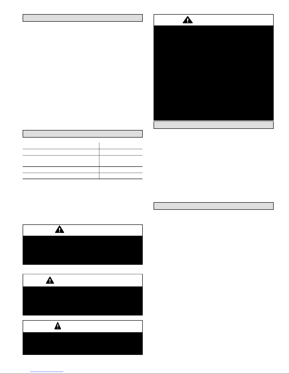
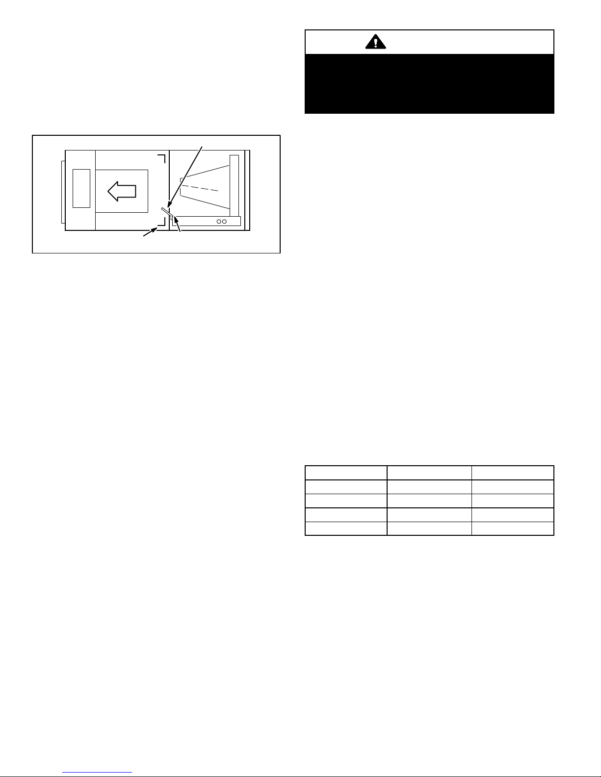
Page 16
HORIZONTAL DRAIN
PAN (MUST BE
REMOVED)
UPFLOW/
DOWNFLOW
DRAIN PAN
Figure 1. Upflow Configuration
NOTE - (-068 model Only) Remove access panels and the
horizontal drip shield along with the corrugated padding
between the blower and coil assembly before operation.
Discard drip shields from the foam pads on top of the unit.
Shields are used for downflow applications only.
1. The horizontal drain pan must be removed when the
coil blower is installed in the upflow position. Removing
horizontal drain pain will allow proper airflow and
increase efficiency.
2. After removing horizontal drain pan, place the unit in
desired location. Set unit so that it is level. Connect
return and supply air plenums as required using sheet
metal screws as illustrated in Figure 1.
3. Install units that have no return air plenum on a stand
that is at least 14” from the floor to allow for proper air
return. Lennox offers an optional upflow unit stand as
listed in Table 1.
Table 1. Optional Unit Side Stand (Upflow Only)
Models
-018/024 45K31
-024/030, -036, -048 and -060
Kit Numbers
45K32
HORIZONTAL RIGHT-HAND DISCHARGE APPLICATION
NOTE - When air handler is located above a finished space,
the secondary drain pan must have a larger footprint than
the air handler. In addition, a 3/4” (19.1MM) overflow drain
line must be:
Connected to secondary drain pan
or
Connected to the overflow drain outlet of the air handler
drain pan.
Use the following procedures to configure the unit for
horizontal right-hand discharge operations:
NOTE - For horizontal applications, a secondary drain pan
is recommended. Refer to local codes.
NOTE - (-068 Model Only) Before operating the unit,
remove access panels and the horizontal drip shield and
the corrugated padding between the blower and coil
assembly. Discard the corrugated padding and the
downflow drip shields from the foam pads on top of the unit.
NOTE - (-068 Model Only) Install the horizontal shield on
the front edge of the horizontal drain pan as illustrated in
Figure 2.
4. No further adjustment is necessary. Set unit so that it is
sloped 1/4 inch (6.35mm) towards the drain pan end of
the unit.
UP-LOAD / DOWNFLOW
DRAIN PAN
HORIZONTAL DRAIN
PAN
NO ADJUSTMENT IS NECESSARY
Figure 2. Right-Hand Discharge Configuration
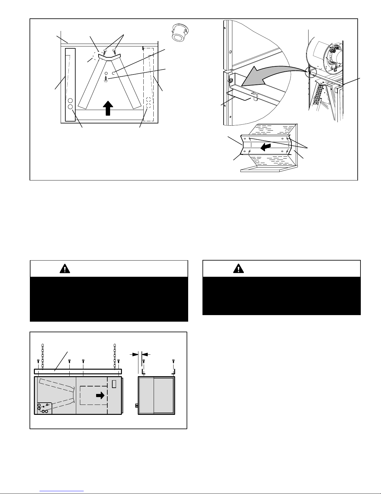
5. If the unit is suspended, the entire length of the cabinet
must be supported. If you use a chain or strap, use a
piece of angle iron or sheet metal attached to the unit
(either above or below) to support the length of the
cabinet. Use securing screws no longer than 1/2 inch
(12.7mm) to avoid damaging the coil or filter as
illustrated in Figure 4. Use sheet metal screws to
connect the return and supply air plenums as required.
HORIZONTAL RIGHT-HAND DISCHARGE APPLICATION
IN HIGH HUMIDITY AREAS
For horizontal applications in high humidity areas remove
the downflow rail closest to the drain pan.
HORIZONTAL DRIP SHIELD (-068
MODELS)
DOWNFLOW RAIL
CBX32MV
Page 16
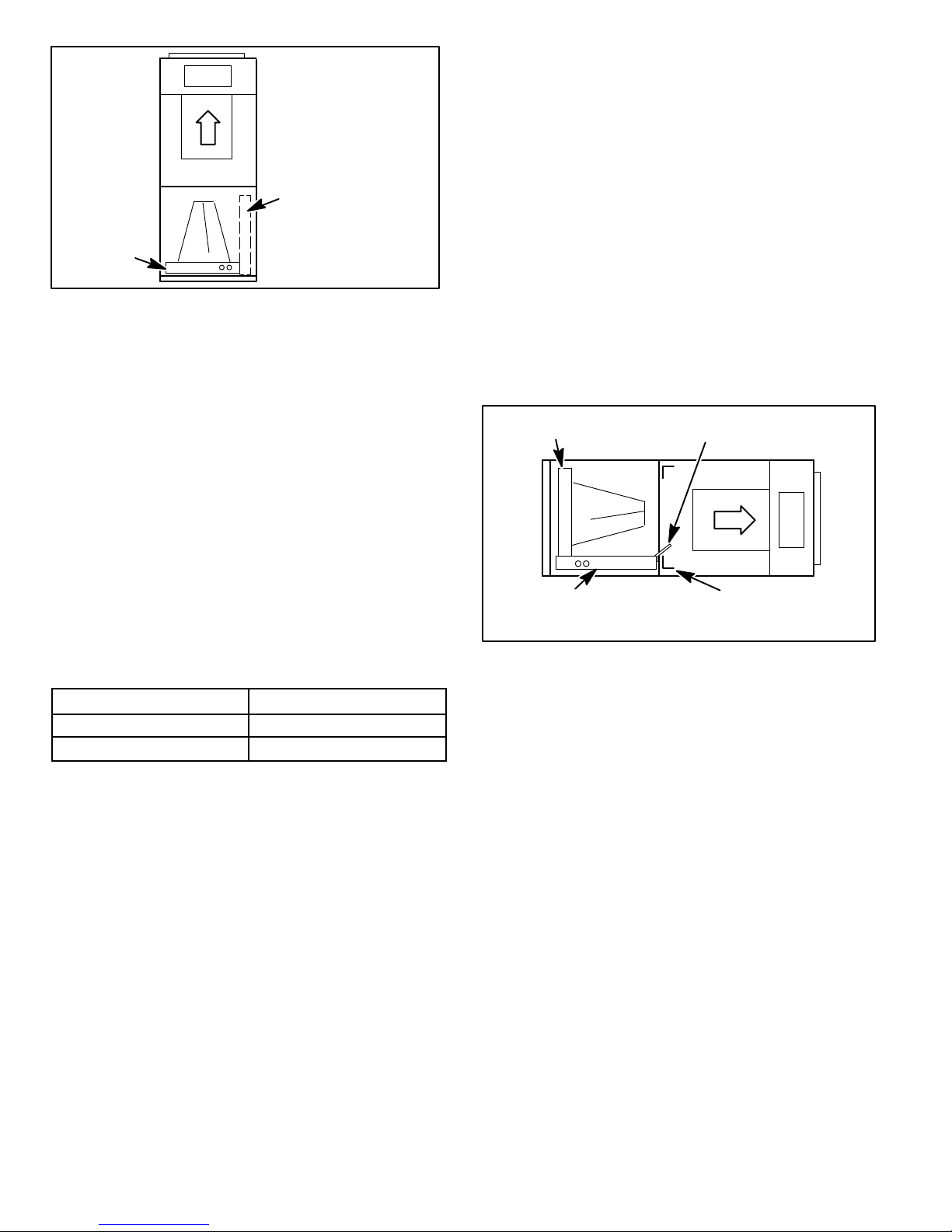
Page 17
CABINET
SUPPORT
DRAIN PAN
REINSTALLED
HERE
TOP CAP ROTATED TO
CORRECT POSITION
90º
BEND
TOP CAP
SCREWS
3/16” PLASTIC
PLUG (REAR COIL
END SEAL)
HORIZONTAL DRIP
SHIELD SCREW
(FRONT COIL END
SEAL)
DRAIN PAN
SHIPPING
LOCATION
INSTALL DRAIN PAN
BETWEEN TAB AND
EXTERIOR INNER WALL.
DETAIL C
REINSTALLED HERE REMOVED FROM HERE
———— DRAIN PLUGS ————
FRONT VIEW
COIL SHOWN IN UPFLOW POSITION FOR EASY
CONVERSION (LEFT-HAND AIR DISCHARGE)
DETAIL A
Figure 3. Field Modification for Left-Hand Discharge
To remove rail:
1. Remove the screws from the rail at the back of unit and
at the cabinet support rail.
2. Remove the downflow rail then replace screws.
3. Seal around the exiting drain pipe, liquid line, and
suction line to prevent humid air from infiltrating into the
unit.
IMPORTANT
When removing the coil, there is possible danger of
equipment damage and personal injury. Be careful when
removing the coil assembly from a unit installed in rightor left-hand applications. The coil may tip into the drain
pan once it is clear of the cabinet. Support the coil when
removing it.
1/2 IN. SCREWS MAXIMUM
ANGLE IRON OR
SHEET METAL
FRONT VIEW END VIEW
Figure 4. Suspending Horizontal Unit
HORIZONTAL LEFT-HAND DISCHARGE APPLICATION
Use the following procedures to configure the unit for
horizontal left-hand discharge operations:
ELECTRICAL INLET
CLEARANCE 4 IN. (102 MM)
TOP CAP
DETAIL B
90º
BEND
ALIGN HOLES WITH
HOLES IN COIL END
PLATE.
BACK COIL
END SEAL
NOTE - For horizontal applications, a secondary drain pan
is recommended. Refer to local codes.
NOTE - (-068 Model Only) Remove access panels and
horizontal drip shield from the corrugated padding between
the blower and coil assembly. Discard the corrugated
padding and the downflow drip shields from the foam pads
on top of the unit. (The shields are used for downflow
applications only.)
IMPORTANT
After removal of drain pan plug(s), check drain hole(s) to
verify that drain opening is fully open and free of any
debris. Also check to make sure that no debris has fallen
into the drain pan during installation that may plug up the
drain opening.
1. Pull the coil assembly from unit. Pull off the horizontal
drain pan.
2. Remove the drain plugs from back drain holes on
horizontal drain pan and reinstall them on front holes.
3. Rotate drain pan 180º front‐to‐back and install it on the
opposite side of the coil.
4. Remove screws from top cap as illustrated in Figure 3,
Detail A.
5. Remove horizontal drip shield screw located in the left
center of the back coil end seal as illustrated in Figure
3, Detail A.
6. Rotate horizontal drip shield 180º front to back.
7. Remove plastic plug from hole located on the left center
of front coil end seal and reinstall plug in back hole on
rear coil end seal.
8. Reinstall horizontal drip shield screw in front coil end
seal. Drip shield should drain downward into horizontal
drain pan inside coil.
Page 17
CBX32MV
Page 18
9. Rotate top cap 180º front‐to‐back and align with
unused screw holes. Holes must align with front and
back coil end plates. The top cap has a 45º bend on one
side and a 90º bend on the other. The 90º bend must be
on the same side as the horizontal drain pan as
illustrated in Figure 3, Detail B.
NOTE - Be very careful when you reinstall the screws into
coil end plate engaging holes. Misaligned screws may
damage the coil.
HORIZONTAL DRIP SHIELD (-068 MODEL)
DOWNFLOW RAIL
FRONT EDGE OF HORIZONTAL
DRAIN PAN
Figure 5. Left-Hand Discharge Configuration
10. From the upload position, flip cabinet 90º to the left and
set into place. Replace coil assembly. Replace coil
assembly. Install drain pan between exterior inner wall
and tab as illustrated in Figure 3, Detail C.
11. (-068 Model Only) Install the horizontal shield on the
front edge of the horizontal drain pan as shown in figure 5.
NOTE - For horizontal applications in high humidity areas,
remove the downflow rail closest to the drain pan. To
remove rail, remove screw from rail at back of unit and at
cabinet support rail. Remove downflow rail then replace
screws. Also, seal around the exiting drain pipe, liquid and
suction lines to prevent infiltration of humid air.
12. Knock out drain seal plate from access door. Secure
plate to cabinet front flange with screw provided.
13. Flip access door and replace it on the unit.
14. Set unit so that it is sloped 1/4 inch (6.35mm) toward
the drain pan end of the unit. Connect return and supply
air plenums as required using sheet metal screws.
15. If suspending the unit, it must be supported along the
entire length of the cabinet. If using chain or strap, use a
piece of angle iron or sheet metal attached to the unit
(either above or below) so that the full length of the
cabinet is supported. Use securing screws no longer
than 1/2 inch (12.7mm) to avoid damage to coil or filter
as illustrated in Figure 4 on page 17. Connect return
and supply air plenums as required using sheet metal
screws.
DOWNFLOW APPLICATION
Use the following procedures to configure the unit for
downflow operations:
CAUTION
If electric heat section with circuit breakers
(ECB29/ECB31) is applied to downflow CBX32MV
unit, the circuit breakers must be rotated 180° to the
UP position. See ECB29/ECB31 installation
instructions for more details.
Table 2 outlines the sizes of the various drip shields.
NOTE — (-068 Model Only) Remove access panels and
horizontal drip shield from the corrugated padding between
the blower and coil assembly.
NOTE — Discard the corrugated padding and the downflow
drip shields from the foam pads on top of the unit. (The
shields are used for downflow applications only.)
1. Remove the coil assembly from the unit.
2. For best efficiency and air flow, remove the horizontal
drain pan from the units in downflow positions as
illustrated in figure 6 on page 19.
3. Rotate cabinet 180º from the upright position. See
figure 6. You may need to first remove the blower
assembly to lighten the cabinet for lifting.
4. Foam tape that is provided creates a seal between the
drip shield and the coil so that water does not leak into
the air stream. The foam tape pieces are precut. Apply
the tape to the drip shields as illustrated in figure 7 and
specified as follows:
Apply two pieces of foam tape provided down both
ends of each shield. The tape should measure
4-3/4” X 2” (120 X 25 mm). Ensure that the tape
covers both sides of the shield equally.
Apply the longer piece of 1‐inch wide foam tape
between the end pieces of tape.
5. From the underside of the coil, install the downflow drip
shield firmly in place as illustrated in figure 8.
Table 2. Downflow Drip Shields (Tape Required)
Units
-018/024 Not Required Not Required
-024/030 15-7/8” 4-11/16”
-036 17-7/8” 4-11/16”
-048, -060, and -068 19-7/8” 4-11/16”
Length Width
CBX32MV
Page 18
Page 19
SIDE
VIEW
HORIZONTAL DRAIN PAN
UP-LOAD /
DOWNFLOW
DRAIN PAN
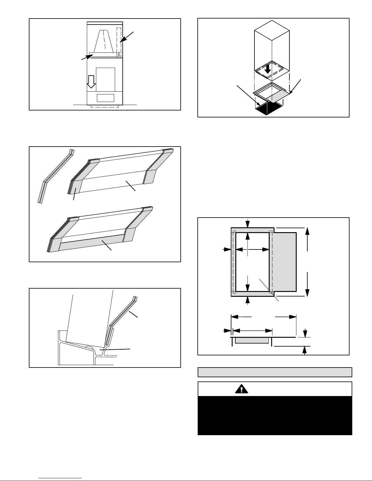
Figure 6. Downflow Discharge Position
DRIP SHIELD
2” WIDE FOAM TAPE
(REMOVE FROM UNIT)
AIR
HANDER
UNIT
COMBUSTIBLE FLOOR
PROPERLY SIZED
FLOOR OPENING
ADDITIVE BASE
Figure 9. Combustible Flooring Additive Base
8. For downflow installation on combustible flooring, an
additive base must be used as illustrated in figure 9 on
page 19.
9. Cut an opening appropriately sized for combustible
base. Base dimensions are illustrated in figure 10.
After opening has been cut, set the additive base into
opening. Connect outlet air plenum to the additive
base. Set the unit on the additive base so flanges of
the unit drop into the base opening and seal against
the insulation strips. The unit is now locked in place.
Install return air plenum and secure with sheet metal
screws.
1‐5/8 (41)
TOP VIEW
1” WIDE FOAM TAPE (LONGER PIECE)
Figure 7. Applying Foam Tape to Drip Shield
COIL
DRIP SHIELD
DRIP PAN
Figure 8. Downflow Drip Shields
6. Replace the coil assembly and blower if you have
removed it. Replace the coil access panel.
7. Set the unit so that it is level. Using sheet metal screws,
connect the return and supply air plenums as required.
NOTE - For downflow application, metal or class I supply
and return air plenums must be used.
11‐3/8
1‐5/8 (41)
1‐5/8 (41)
5/8 (16)
(289)
-018/-024 15
(381)
-024/-030 AND
UP 20 (508)
SUPPLY AIR OPENING
24 (610) -068 ONLY
22‐1/8 (562) OTHER MODELS
13‐3/8 (340)
OPENING
SIDE VIEW
-018/-024 08-1/4 (464)
-024/-030 and up 23-1/4 (591)
INCHES (MM)
2 (51)
Figure 10. Downflow Combustible Base Dimensions
Brazing Connections
WARNING
Polyol ester (POE) oils used with HFC-410A refrigerant
absorb moisture very quickly. It is very important that
the refrigerant system be kept closed as much as
possible. DO NOT remove line set caps or service valve
stub caps until you are ready to make connections.
Page 19
CBX32MV
Page 20

WARNING
Danger of fire. Bleeding the refrigerant
charge from only the high side may result
in the low side shell and suction tubing
being pressurized. Application of a
brazing torch while pressurized may
result in ignition of the refrigerant and oil
mixture - check the high and low
pressures before unbrazing.
IMPORTANT
To prevent the build up of high levels of nitrogen when
purging, be sure it is done in a well ventilated area. Purge
low pressure nitrogen (1 to 2 psig) through the refrigerant
piping during brazing. This will help to prevent oxidation
and the introduction of moisture into a system.
CBX32MV
Page 20
Page 21
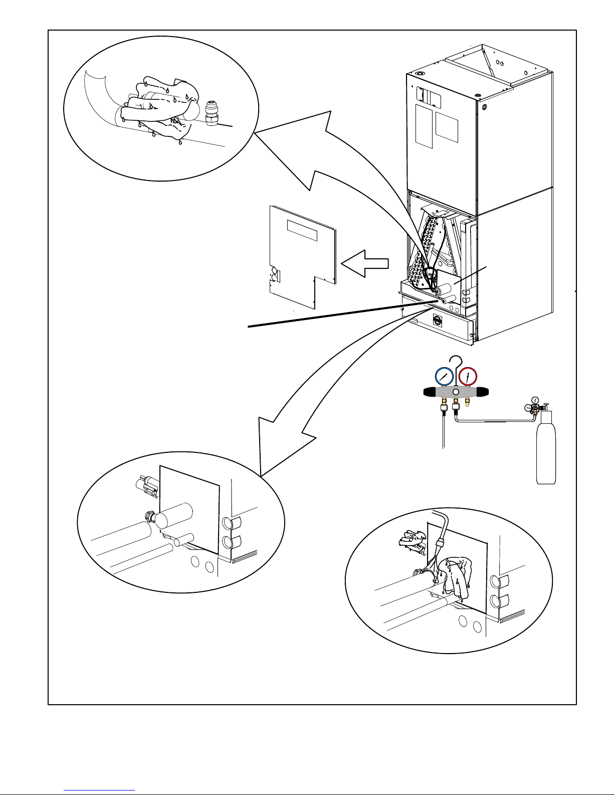
PLEASE READ IMPORTANT ISSUES CONCERNING BRAZING
OPERATIONS ON PAGE 10 BEFORE PROCEEDING.
USE A WET RAG TO PROTECT CTXV
C
SENSING BULB WHEN BRAZING
SUCTION LINE CONNECTIONS.
NOTE — REFER TO OUTDOOR UNIT INSTALLATION INSTRUCTIONS
FOR REFRIGERANT PIPING SIZE REQUIREMENTS.
NOTE - Use silver alloy brazing rods with five or six
percent minimum silver alloy for copper-to-copper
brazing, 45 percent alloy for copper-to-brass and
copper-to-steel brazing.
REMOVE ACCESS PANEL
A
REMOVE RUBBER PLUG FROM BOTH LIQUID
B
AND SUCTION LINES
NOTE — CBX32MV SERIES UNITS USE NITROGEN OR DRY
AIR AS A HOLDING CHARGE. IF THERE IS NO PRESSURE
WHEN THE RUBBER PLUGS ARE REMOVED, CHECK THE
COIL FOR LEAKS BEFORE INSTALLING.
EITHER REMOVE OR PUSH PIPE WRAPPING BACK
D
THROUGH HOLE IN PIPING PLATE BEFORE LINE
SET CONNECTION AND BRAZING.
LOW
PIPING
PLATE
HIGH
CONNECT PIPES
E
NOTE — REFRIGERANT LINE SETS
SHOULD BE ROUTED TO ALLOW
FILTER ACCESSIBILITY.
REPEAT PREVIOUS PROCEDURE FOR LIQUID
I
LINE.
FLOW REGULATED NITROGEN (AT 1 TO 2 PSIG)
THROUGH THE REFRIGERATION GAUGE SET INTO THE
VALVE STEM PORT CONNECTION ON THE OUTDOOR
UNIT LIQUID LINE SERVICE VALVE AND OUT OF THE
VALVE STEM PORT CONNECTION ON THE SUCTION
SERVICE VALVE.
PLACE A WET RAG AGAINST PIPING
G
PLATE AND AROUND THE SUCTION
LINE CONNECTION. A
BRAZE CONNECTION. ALLOW PIPE TO
H
COOL BEFORE REMOVING WET RAG
FROM CTXV SENSING BULB AND PIPING
PANEL AREA.
CONNECT GAUGES AND
F
START NITROGEN FLOW
NITROGEN
REFER TO INSTRUCTIONS PROVIDED WITH OUTDOOR UNIT FOR
LEAK TESTING, EVACUATING AND CHARGING PROCEDURES
Figure 11. Brazing Connections
Page 21
CBX32MV
Page 22

WARNING
When using a high pressure gas such as
dry nitrogen to pressurize a refrigeration
or air conditioning system, use a regulator
that can control the pressure down to 1 or
2 psig (6.9 to 13.8 kPa).
Condensate Drain Requirements
IMPORTANT
After removal of drain pan plug(s), check drain hole(s) to
verify that drain opening is fully open and free of any
debris. Also check to make sure that no debris has fallen
into the drain pan during installation that may plug up the
drain opening.
CAUTION
Brazing alloys and flux contain materials which are
hazardous to your health.
Avoid breathing vapors or fumes from brazing operations.
Perform operations only in well ventilated areas.
Wear gloves and protective goggles or face shield to
protect against burns.
Wash hands with soap and water after handling brazing
alloys and flux.
Table 3. CBX32MV Refrigerant Connections and Line
Set Requirements
Models
-018/024
-024/030
and -036
-048
-060
-068
NOTE — Some applications may require a field provided 7/8” to
1-1/8” adapter
Liquid
Line
3/8”
(10mm)
3/8”
(10mm)
3/8”
(10mm)
3/8”
(10mm)
3/8”
(10mm)
NOTE - When installing refrigerant lines longer than 50
feet, see the Lennox Refrigerant Piping Design and
Fabrication Guidelines, CORP. 9351-L9, or contact Lennox
Technical Support Product Applications for assistance.
Vapor /
Suction
Line
5/8”
(16mm)
3/4”
(19mm)
7/8”
(22mm)
7/8”
(22mm)
1-1/8”
(29mm)
L15 Line Set
L15 line set sizes are
dependent on unit matchups.
See CBX32MV Product
Specification bulletin to
determine correct line set
sizes.
Field-fabricated
MAIN DRAIN
Connect the main drain and route downward to drain line or
sump. Do not connect drain to a closed waste system. See
Figure 13 for typical drain trap configuration.
OVERFLOW DRAIN
It is recommended that the overflow drain is connected to a
overflow drain line for all units. If overflow drain is not
connected, it must be plugged with provided cap.
For downflow orientation, the overflow drain MUST be
connected and routed to a overflow drain line. See Figure
13 for main and overflow drain locations based on coil
orientation.
LEFT-HAND AIR
DISCHARGE
OVERFLOW
DRAIN ON LEFT
UPFLOW OR
DOWNFLOW
RIGHT-HAND AIR
DISCHARGE
MAIN DRAIN ON
RIGHT
Figure 12. Main and Overflow Drain Locations based
on Coil Orientation
BEST PRACTICES
The following best practices are recommended to ensure
better condensate removal:
Main and overflow drain lines should NOT be smaller
than both drain connections at drain pan.
Overflow drain line should run to an area where
homeowner will notice drainage.
It is recommended that the overflow drain line be
vented and a trap installed. Refer to local codes.
CBX32MV
Page 22
Page 23

ABOVE
FINISHED
SPACE?
OVERFLOW DRAIN LINE
ALWAYS RUN AN OVERFLOW DRAIN LINE. IF NOT POSSIBLE TO
ROUTE OVERFLOW DRAIN LINE, INSTALL LOW VOLTAGE
OVERFLOW SWITCH KIT. WIRE KIT TO SHUT DOWN
COMPRESSOR PER INSTRUCTIONS.
LENNOX #
X3169
COMPACT OVERFLOW SWITCH WITH 3/4” FEMALE SLIP INLET
NO
AND MALE ADAPTER, TWO PART DESIGN FOR USE WHERE
OBSTRUCTIONS PREVENT DIRECT THREADING
CLEAN OUT
PRESS IN
(DO NOT GLUE)
VENT MUST EXTEND
ABOVE HEIGHT OF
COIL DRAIN PAN BY
TWO INCHES (51MM)
VENT
MAIN
MAIN
DRAIN
CUT TO
REQUIRED
LENGTH
PROVIDED
PIPE NIPPLE
SIDE VIEW
2
FOR NEGATIVE PRESSURE COILS (BLOWER
AFTER COIL) TRAPS ARE REQUIRED ON ALL
DRAIN LINES CONNECTED TO COIL.
AIR HANDLER DRAIN PAN
OVERFLOW
DRAIN
YES
NOTE — WHEN A AIR HANDLER IS LOCATED
ABOVE A FINISHED SPACE THE SECONDARY
DRAIN PAN MUST HAVE A LARGER FOOTPRINT
THAN THE AIR HANDLER.
DRAIN
SECONDARY
DRAIN PAN
WHEN A COIL IS LOCATED ABOVE A FINISHED SPACE, A
3/4” (19.1MM) SECONDARY DRAIN LINE MUST BE:
CONNECTED TO SECONDARY DRAIN PAN
OR
CONNECTED TO THE OVERFLOW DRAIN OUTLET OF
THE AIR HANDLER DRAIN PAN.
TRAPS MUST BE DEEP ENOUGH TO OFFSET MAXIMUM STATIC DIFFERENCES —
GENERALLY, TWO INCHES (51MM).
1
LENNOX P-TRAP 49P66 REQUIRES A LARGER INSTALLATION SPACE THAN THE J-TRAP 91P90.
2
PIPE NIPPLE PROVIDED IN BAG ASSEMBLY - SCH 80, 3/4” I. D. X 5” - 34K7401 (1): CUT THE PIPE IN HALF AND USE IT TO ROUTE THE MAIN DRAIN.
1” X 3/4” X 3/4”
REDUCING
TEE WITH
PLUG
1
LENNOX
P-TRAP
49P66, J-TRAP #
91P90 OR ANY
PVC SCH 40 P- OR
J-TRAP 3/4”
Figure 13. Typical Main and Overflow Drain Installations
Inspecting and Replacing Filters
IMPORTANT
Filter access door must be in place during unit operation.
Excessive warm air entering the unit from unconditioned
space may result in water blow-off problems.
Unit Model No. Filter Size Inches (mm)
-018/024 15 X 20 x 1(381 x 508 x 25)
-024/030 20 x 20 x 1(508 x 508 x 25)
-036 20 x 20 x 1(508 x 508 x 25)
-048 and -060 20 x 24 x 1(508 x 610 x 25)
-068 20 x 25 x 1(508 x 635 x 25)
Table 4. Filter Dimensions
2”
(51MM)
TRAP DEPTH
TO APPROVED
DRAIN
DRAIN LINE SHOULD
SLOPE A MINIMUM OF
ONE INCH PER 10
FEET (25MM PER 3
METERS)
Filters may be duct-mounted or installed in the cabinet. A
filter is installed at the factory. Note that filter access door
fits over access panel. Air will leak if the access panel is
placed over the filter door.
Filters should be inspected monthly and must be cleaned or
replaced when dirty to assure proper furnace operation.
To replace filter:
1. Loosen the thumbscrews holding the filter panel in
place.
2. Slide the filter out of the guides on either side of cabinet.
3. Insert new filter.
4. Replace panel.
See Table 4 for replacement filter sizes.
Sealing the Unit
WARNING
There must be an airtight seal between the bottom of the
air handler and the return air plenum. Use fiberglass
sealing strips, caulking, or equivalent sealing method
between the plenum and the air handler cabinet to ensure
a tight seal. Return air must not be drawn from a room
where this air handler or any gas-fueled appliance (i.e.,
water heater), or carbon monoxide-producing device
(i.e., wood fireplace) is installed.
Seal the unit so that warm air is not allowed into the cabinet.
Warm air introduces moisture, which results in water
blow-off problems. This is especially important when the
unit is installed in an unconditioned area.
Page 23
CBX32MV
Page 24

Make sure the liquid line and suction line entry points are
sealed with either the provided flexible elastomeric thermal
insulation, or field provided material (e.g. Armaflex,
Permagum or equivalent). Any of the previously mentioned
materials may be used to seal around the main and
auxiliary drains, and around open areas of electrical inlets.
Field Control Wiring
WARNING
Electric Shock Hazard.
Can cause injury or death.
Foil‐faced insulation has conductive characteristics simi
lar to metal. Be sure there are no electrical connections
within a ½” of the insulation. If the foil‐faced insulation
comes in contact with electrical voltage, the foil could pro
vide a path for current to pass through to the outer metal
cabinet. While the current produced may not be enough
to trip existing electrical safety devices (e.g. fuses or cir
cuit breakers), the current can be enough to cause an
electric shock hazard that could cause personal injury or
death.
Wiring must conform to the current National Electric Code
ANSI/NFPA No. 70, or Canadian Electric Code Part I, CSA
Standard C22.1, and local building codes. Refer to
following wiring diagrams. See unit nameplate for minimum
circuit ampacity and maximum over-current protection
size.
Select the proper supply circuit conductors in
accordance with Tables 310-16 and 310-17 in the
National Electric Code, ANSI/NFPA No. 70 or Tables 1
through 4 in the Canadian Electric Code, Part I, CSA
Standard C22.1.
Separate openings have been provided for 24V low voltage
and line voltage. Refer to the dimension illustration for
specific location.
CAUTION
USE COPPER CONDUCTORS ONLY.
Wiring connections
1. Install line voltage power supply to unit from a
properly-wired circuit breaker.
2. Ground unit at unit disconnect switch or to an earth
ground.
NOTE - Connect conduit to the unit using a proper conduit
fitting. Units are approved for use only with copper
conductors. A complete unit wiring diagram is located on
the back side of the unit's access panel.
3. Install low voltage wiring from outdoor to indoor unit
and from thermostat to indoor unit.
NOTE - For proper voltages, select control wiring gauge per
the charts on page 28.
WARNING
Run 24V Class II wiring only through specified low voltage
opening. Run line voltage wiring only through specified
high voltage opening. Do not combine voltage in one
opening.
CBX32MV
Page 24
Page 25

Air Handler or Furnace Control
DS
Heat Pump or Air Conditioner Control
W
L
Y2
Y1
O
DS
C
i−
i+
R
O
L
H
DH
R
C
Y1
Y2
G
W3
W2
W1
iComfortt
THERMOSTAT
C
i−
i+
R
OUTDOOR UNIT
C
i−
i+
R
C
THERMOSTAT
i−
i+
R
Outdoor sensor for outdoor
temperature display
OUTDOOR AIR SENSOR
(Optional).
Figure 14. Control (Field) Wiring — Communicating System (iComfortt thermostat)
Page 25
CBX32MV
Page 26

AIR
CONDITIONER
UNIT
(TWO-STAGE)
BROWN
YELLOW
BLUE
BLACK
RED
CBX32MV
R
2
W3
W2
W1
O
3
Y1
Y2
G
DS
C
COMFORTSENSE
7000
R
H
1
W2
W1
O
L
Y1
Y2
G
D
B
C
AIR HANDLER CONTROL COMES FROM FACTORY WITH A
METAL JUMPERS BETWEEN W1 TO W2 AND W2 TO W3. SEE
FIGURE 20 FOR HEAT SECTION CONFIGURATION.
1
CONNECTED ON UNIT WITH LSOM. RESISTOR KIT (CAT #
47W97) IS REQUIRED WHEN CONNECTING THE
2
COMFORTSENSE 7000 (CATALOG# Y0349) WITH THE LSOM 2.
RESISTOR KIT NOT REQUIRED WHEN USING COMFORTSENSE
7000 CATALOG# Y2081).
3
L CONNECTION WIRED ON UNITS WITH LSOM.
IMPORTANT — USE CARE WHEN CUTTING LINKS TO
PREVENT DAMAGE TO CONTROL. SEE FIGURE 19,
CBX32MV JUMP AND LINK GUIDE FOR FURTHER
DETAILS.
CUT ON-BOARD LINK Y1-Y2 FOR TWO-STAGE AC
DO NOT CUT ON-BOARD LINK R -O.
CUT ON-BOARD LINK R-DS WHEN DEHUMIDIFICATION TERMINAL IS USED.
Figure 15. Control (Field Wiring) — Cooling Application (Non-Communicating)
AIR HANDLER
CONTROL
Y1-Y2
2-STAGE
COMPR
R-O
HEAT
PUMP
R-DS
DEHUM
OR
HARMONY
CUT FOR OPTION
HEAT PUMP
UNIT
(TWO-STAGE)
R
W1
L
Y1
Y2
OUT
BL
CC
CBX32MV
RR
W3
W2
W1 W1
OO
2
Y1
G
DS
3
Y2
Figure 16. Control (Field Wiring) — Heat Pump (Non-Communicating)
COMFORTSENSE
7000
H
W2
O
L
Y1
Y2Y2
G
D
T
B
T
C
1
O. D.
SENSOR
(X2658)
X2658 OUTDOOR SENSOR IS REQUIRED FOR OUTDOOR
1
TEMPERATURE DISPLAY, DEW POINT CONTROL, HEAT
PUMP AND DUAL FUEL BALANCE POINTS.
CONNECTED ON UNIT WITH LSOM. RESISTOR KIT (CAT
2
# 47W97) IS REQUIRED WHEN CONNECTING THE
COMFORTSENSE 7000 (CATALOG# Y0349) WITH THE
LSOM 2. RESISTOR KIT NOT REQUIRED WHEN USING
COMFORTSENSE 7000 CATALOG# Y2081).
FIELD PROVIDED JUMPER BETWEEN Y2 OUT BL ON
3
HEAT PUMP TO Y2 ON CX32MV.
IMPORTANT — USE CARE WHEN CUTTING LINKS TO
PREVENT DAMAGE TO CONTROL. SEE FIGURE 19,
CBX32MV JUMP AND LINK GUIDE FOR FURTHER
DETAILS.
CUT ON-BOARD LINK Y1-Y2 FOR TWO-STAGE HP
CUT ON-BOARD LINK R -O.
CUT ON-BOARD LINK R-DS WHEN DEHUMIDIFICATION TERMINAL IS USED.
Y1-Y2
2-STAGE
COMPR
R-O
HEAT
PUMP
R-DS
DEHUM
OR
HARMONY
CUT FOR OPTION
CBX32MV
Page 26
Page 27

OUTDOOR
SENSOR
(X2658)
RED
RED
FAN
RELAY
PUR
BLK
D
BLK
PUR
EDA UNIT
YEL
BLU
BLK
BRN
CBX32MV
OUTDOOR UNIT
NOTES -
NOT REQUIRED FOR APPLICATIONS WITHOUT LSOM
/1\
NOT REQUIRED WITH SINGLE‐SPEED OUTDOOR FAN
/2\
NOT REQUIRED FOR SINGLE STAGE
/3\
AIR HANDLER CONTROL COMES FROM FACTORY WITH A METAL
4
JUMPERS BETWEEN W1 TO W2 AND W2 TO W3. SEE FIGURE 20
FOR HEAT SECTION CONFIGURATION.
.
4
T
T
CONNECTED ON UNIT WITH LSOM.
RESISTOR KIT (CAT # 47W97) IS
REQUIRED WHEN CONNECTING THE
COMFORTSENSE 7000 (CATALOG#
Y0349) WITH THE LSOM 2. RESISTOR
KIT NOT REQUIRED WHEN USING
COMFORTSENSE 7000 CATALOG#
Y2081).
COMFORTSENSE
7000 THERMOSTAT
CUT ON-BOARD LINK R-DS WHEN DEHUMIDIFICATION
IMPORTANT — USE CARE WHEN CUTTING LINKS TO
PREVENT DAMAGE TO CONTROL. SEE FIGURE 19,
CBX32MV JUMP AND LINK GUIDE FOR FURTHER
DETAILS.
CUT ON-BOARD LINK Y1-Y2 FOR TWO-
DO NOT CUT ON-BOARD LINK R -O.
STAGE A/C
TERMINAL IS USED.
Y1-Y2
2-STAGE
COMPR
R-O
HEAT
PUMP
R-DS
DEHUM
OR
HARMONY
CUT FOR OPTION
Figure 17. Control (Field Wiring) — Cooling Application (Humiditrol
Relay Wiring) Non-Communicating
OUTDOOR UNIT
FAN RELAY (NOT REQUIRED
WITH SINGLE−SPEED
OUTDOOR FAN)
RED
PURPLE
BLACK
YELLOW
BLUE
BROWN (NOT USED FOR APPLICATIONS WITHOUT LSOM
BLUE (NOT REQUIRED FOR SINGLE STAGE)
IMPORTANT — USE CARE WHEN CUTTING LINKS TO
PREVENT DAMAGE TO CONTROL. SEE FIGURE 19,
CBX32MV JUMP AND LINK GUIDE FOR FURTHER
DETAILS.
RED
BLACK
PURPLE
CUT ON-BOARD LINK Y1-Y2 FOR TWO-STAGE A/C ONLY
CUT ON-BOARD LINK R-DS WHEN DEHUMIDIFICATION
CBX32MV
®
and Second-Stage Outdoor Fan
COMFORTSENSE
7000 THERMOSTAT
OUTDOOR
SENSOR
T
T
(X2658)
2-STAGE
COMPR
CUT ON-BOARD LINK R -O.
TERMINAL IS USED.
DEHUM
HARMONY
Y1-Y2
R-O
HEAT
PUMP
R-DS
OR
CUT FOR OPTION
Figure 18. Control (Field Wiring) — Heat Pump Application (Humiditrol
Fan Relay Wiring) Non-Communicating
Page 27
®
and Second-Stage Outdoor
CBX32MV
Page 28

SENSOR CONNECTIONS AND WIRING
REQUIREMENTS
The following are sensor connections and wiring
requirements for the discharge air and outdoor air sensors.
Discharge Sensor (DAT)
The Air Handler Control has two screw terminals marked
Discharge Air Sensor. The sensor is REQUIRED for
EVENHEAT operation and is field installed and ordered
separately using Lennox Catalog # 88K38.
In the EVENHEAT mode, the discharge air sensor cycles
the electric heating elements as needed to maintain the Air
Handler control EVENHEAT jumper selected discharge
setpoint.
The discharge air sensor should be mounted downstream
of the electric heat elements as illustrated in Figure 26,
Detail A. It must be placed in a location with unobstructed
airflow, where other accessories (such as humidifiers, UV
lights, etc.) will not interfere with its accuracy.
Wiring distance between the Control and the discharge air
sensor should not exceed 10 feet (3 meters) when wired
with 18-gauge thermostat wire.
Outdoor Air Sensor
This is a two screw terminal for connection to a Lennox
X2658 outdoor temperature sensor. The Control takes no
action on the sensor status other than to communicate the
temperature to the RSBus network. Wiring distance
between the Control and outdoor temperature sensor
should not exceed 200 feet when wired with 18-gauge
thermostat wire.
Minimum temperature: -40ºF (-40ºC)
Maximum temperature: 70ºF (158ºC)
AIR HANDLER CONTROL 9-PIN CONNECTOR (P8)
1. Air Handler (no electric heat) — Two wire factory
harness (wired to pins 7 and 8) which provides 230
VAC power to Air Handler Control.
2. Air Handler (with electric heat) — Eight wire factory
harness (all pin positions are wired as noted in Table 5).
NOTE - See Figure 26, Detail B for wire colors.
Table 5. Electric Heat Connection (P8)
Position Function / Description
1 Heat stage 1 relay coil
2 Heat stage 2 relay coil
3 Relay coil return
4 Heat stage 3 relay coil
5 Heat stage 4 relay coil
6 Heat stage 5 relay coil
7 L1 230VAC supply from heater kit
8 L2 230 VAC supply from heater kit
9 Not Used
CONTROL CONNECTIONS AND WIRING
REQUIREMENTS
This sections provides information on communicating and
non-communicating control connections and wire run
lengths.
Table 6. Air Handler Control Connections —
Communicating
Label Label Function
R 24VAC
Thermostat
Outdoor Unit
Link
i+ RSbus data high connection
i- RSbus data low connection
C 24VAC command (ground)
R 24VAC
i+ RSbus data high connection
i- RSbus data low connection
C 24VAC command (ground)
i+
Not used.
i-
Table 7. Run Length — Communicating
Wire Run Length AWG # Insulation/Core Types
Maximum length of wiring
for all connections on the
RSbus is limited to 1500
feet (457 meters).
18
Color-coded, temperature
rating 95
solid core. (Class II Rated
Wiring)
º
F (35ºC) minimum,
CBX32MV
Page 28
Page 29

Table 8. Air Handler Control Connections
Function
Indoor Control
Terminal Label
W1 (Input)
W2 (Input)
W3 (Input)
Y1 & Y2 (Input/
Output)
G (Input)
C
R The R terminal shall be capable of providing the power to the thermostat and all the associated loads.
O (Input/Output)
DS (Input)
DH (Output) The DH terminal provides a 24VAC output for dehumidification needs in communicating systems.
H (Output) The H terminal provides a 24VAC output for humidification needs in both communicating and non-communicating mode.
L (Input)
Non-Communicating
Room Thermostat
(Indoor and Outdoor -24 volts)
Indicates a first-stage heating demand.
This input is an anticipator for the ther
mostat.
Indicates a second-stage heating de
mand. W1 input must be active to recog
nize second-stage heat demand.
Indicates a third-stage heating demand.
W1 and W2 inputs must be active to rec
ognize third-stage heat demand.
Room thermostat inputs 24 volts to the
Y1 and Y2 terminals on the indoor con
trol. The 24 volt signal is then passed
through to the outdoor unit. During a
second-stage demand, both Y1 and Y2
are active. The Y1 terminal is connected
to Y2 by link (Solid jumper on control
that would be cut for 2 stage applica
tions)
Indicates a 24 volt indoor blower de
mand.
The C terminal shall interconnect the signal ground of the room thermostat with secondary transformer ground (TR) and
chassis ground (GND)
Room thermostat inputs 24 volts to the
O terminal on the indoor control. The O
terminal is connected to R by link (Solid
jumper on control that would be cut if
unit was a heat pump)
Used for Harmony III zoning systems, or
thermostat with dehumidification capa
bility. The DS terminal is connected to R
by link (Solid jumper on control that
would be cut if for the above applica
tions).
Harmony III control - This will allow the
control to vary the voltage signal to the
indoor blower motor to control required
CFM.
Dehumidification - Allow a 24 volt sig
nal on the DS to turn off and on the dehu
midification mode.
The L terminal is provided for connection to devices with Lennox System Operation Monitor (LSOM) capabilities. The control
interprets the fault signals and transmits them as an alarm message on the communication line. There are ten (10) identified
LSOM fault codes. Each is mapped to the communication Alarm codes.
Indoor Communicating
Outdoor Non-Communicating
N/A N/A
N/A N/A
N/A N/A
The room thermostat communicated
with the indoor control. The indoor con
trol outputs 24 volts on its Y1 and Y2
terminals which are hard wired to the
non-communicating outdoor unit.
In a communicating system, ”G” input to
indoor control is used by non-communi
cating IAQ devices (such as LVCS, HRV
or ERV) to ensure indoor blower de
mand.
The room thermostat communicated
with the indoor control. The indoor con
trol outputs 24 volts on its O terminals
which are hard wired to the non-com
municating outdoor unit. If there is 24
volts on O, the reversing valve will be
energized and the outdoor unit will run in
the cooling mode. If O does not have 24
volts, the outdoor unit will run in heating
mode.
N/A N/A
Full Communication
(Indoor & Outdoor)
In a full communicating system, no
wiring is required on Y1 and Y2 termi
nals.
In communicating system “G” input to
indoor control is used by non-communi
cating IAQ devices (such as LVCS, HRV
or ERV) to ensure indoor blower de
mand.
In a full communicating system, O termi
nal is not wired.
Table 9. Run Length — Non-Communicating
Wire Run Length AWG # Insulation/Core Types
Less than 100' (30m) 18
More than 100' (30m) 16
Color-coded, temperature rating 95ºF (35ºC) minimum, solid
core. (Class II Rated Wiring)
Page 29
CBX32MV
Page 30

JUMPER & LINK GUIDE
COOLING MODE
BLOWER SPEED
(COOLING & HP MODE)
HIGH
SPEED
1
2
3
*
MEDIUM-HIGH
SPEED
1
2
3
MEDIUM-LOW
SPEED
1
2
3
LOW
SPEED
1
2
3
4
4
4
4
HEATING MODE
BLOWER SPEED
(ELECTRIC HT MODE)
*
HIGH
SPEED
1
2
3
MEDIUM-HIGH
SPEED
1
2
3
MEDIUM-LOW
SPEED
1
2
3
LOW
SPEED
1
2
3
4
4
4
PUSH
4
BUTTON
ON-BOARD LINK
OPTION SELECTION
1
2-STAGE
(JUMPERS Y1 to Y2)
COMPRESSOR LINK
HEAT PUMP LINK
(JUMPERS R to O)
HARMONY LINK
(JUMPERS R to DS)
DEHUMIDIFICATION-
*
1-STG COMPRESSOR
Y1-Y2
DO NOT CUT
COMPR
2 STAGE
A/C UNIT
*
DO NOT CUT
R-0
HEAT
NO HARMONY ZONING
*
OR NO
COMFORTSENSE 7000
W/ DS CONNECTION
DO NOT CUT
PUMP
R-DS
or
DEHUM
2-STG COMPRESSOR
Y1-Y2
2 STAGE
HEAT PUMP UNIT
CUT LINK
1
HARMONY ZONING
C0MFORTSENSE 7000
W/ DS CONNECTION
1
CUT LINK
HARMONY
CUT LINK
COMPR
R-0
HEAT
OR
PUMP
R-DS
1
or
DEHUM
HARMONY
FUSE 3 AMP
XFMR24V
24 VAC
COM
2
3
6
5
9
8
XFMR LINE
L2
L2
G
EARTH
INDOOR BLOWER
SIGNAL
456
12 3
BLOWER
ADJUST SELECTION
*
NORMAL
+
NORM
(+ 10%)
SETTING
+
NORM
(-10%)
SETTING
NORM+-
-
-
1
4
7
L1
HEAT
1234
COOL
1234
DELAY
P8
L1
INDOOR
BLOWER
POWER
I +
1234
ADJUST
NORM +
I + I -RC
OUTDOOR UNIT
I -
LINK
COOLING BLOWER RAMPING
(COOLING MODE UNLESS NOTED)
DELAYPROFILE #4
*
OFF-50%-82%100%-50%-OFF
PROFILE #3
DELAY
OFF-82%-100%-OFF
DELAY
PROFILE #2
CLG
OFF 100% DEMAND
SATISFIED 100% FOR 45
SECONDS OFF
HP
OFF 30 SECOND DELAY
100% DEMAND
SATISFIED 100% FOR 45
SECOND OFF
DELAY
PROFILE #1
OFF-100%-OFF
HUMIDITROL
C
HUMIDIFICATION
SMART
EVENHEAT
85
BLOWER
ONLY CFM
-
1234
I + I -RC
THERMOSTAT
7-SEGMENT LED
DH
AUTO
100
1
1
1
1
115
2
2
2
2
3
3
3
3
Y1-Y2
130
OUTDOOR
AIR SENSOR
4
4
4
4
2-STAGE
COMPR
R-O
HEAT
PUMP
DISCHARGE
AIR SENSOR
CONTINUOUS FAN
BLOWER SPEED
HIGH
SPEED
(100%)
MEDIUM-HIGH
SPEED
(70%)
* MEDIUM-LOW
SPEED
(38%)
LOW
SPEED
(28%)
OR
R-DS
DEHUM
HARMONY
-CUT ON-BOARD LINK (SOLDER TRACE) COMPLETELY
THROUGH BOTH LAYERS ON THE CONTROL BOARD
1
IMPORTANT: USE CARE WHEN CUTTING LINKS TO
PREVENT DAMAGE TO CONTROL.
DS
O
L
H
DH
R
C
Y1
Y2
G
W3
W2
W1
FACTORY
JUMPER
1
2
3
4
1
2
3
4
1
2
3
4
1
2
3
4
STANDARD HEAT MODE
(DEFAULT)
STANDARD
HEAT MODE
(STAGED BY TSTAT)
EVENHEATER MODE
-ENABLED WITH OPTIONAL
DISCHARGE AIR SENSOR
*
85
DEGREE TARGET
DISCHARGE
TEMPERATURE
100
DEGREE
TARGET
115
DEGREE
TARGET
130
DEGREE
TARGET
* INDICATES FACTORY DEFAULT SETTING
85
110
115
85
85
85
130
85
110
115
130
110
115
130
110
115
130
110
115
130
HUMIDIFICATION MODE
HUMIDIFICATION MODE
24VAC OUTPUT ON ”H”
FOR HUMIDIFIER OR
ACCESSORY INTERLOCK
*
SMART MODE
- ”H” ENABLED WHEN
HEAT ACTIVE
(HP or ELECT. HT)
AUTO MODE
- ”H” ENABLED WHEN
BLOWER ACTIVE
& NO CLG
OR DEHUM
SMART
SMART
AUTO
AUTO
CBX32MV
Figure 19. Air Handler Configuration
Page 30
Page 31

Air Handler Control Button, Display and
Jumpers
Use Figure 19 as reference for jumper settings. If any of the
referenced jumpers are missing, the Air Handler Control
will display Error Code 130 as per Table 10, and the Air
Handler Control will automatically use the factory default
settings shown in Figure 19)
IMPORTANT
Before changing any clippable links or jumper settings,
make sure the motor has completely stopped. Any
changes will not take place while the motor is running.
PUSH BUTTON
An on-board push button is provided for the purpose of
placing the Air Handler Control in different operation modes
and can be used to recall stored error codes. When button
is pushed and held, Air Handler Control will cycle through a
menu of options depending on current operating mode.
Every three seconds a new menu item will be displayed. If
the button is released while that item is shown on the
display, Air Handler Control will enter displayed operating
mode, or execute defined operation sequence for that
menu option. Once all items on menu have been displayed
the menu resumes from the beginning (if button is still held).
1. Press the diagnostic push button and hold it to cycle
through a menu of options. Every five seconds a new
menu item will be displayed. Release the button when
the desired mode is displayed.
When the solid “E” is displayed, the control enters the Error
2.
Code Recall mode. Error Code Recall mode menu options:
No change
3. (displaying error history) remains in Error Code Recall mode;
solid “” exits Error Code Recall mode; and solid “c” clears the
error history. Must press button while flashing “c” is displayed
to clear error codes
4. When the solid “-” is displayed, the control enters the error
recall mode. The error recall menu options: Solid “C” starts
pressure switch calibration; blinking “-” exits current active
mode.
JUMPERS
Jumpers are used for non-communicating mode only.
1. Humidification — Controls the status of H terminal on
the thermostat block. Configurations are as follows:
If jumper is installed in SMART Humidification
position (Default), H terminal is active if heat
demand is present and indoor blower is running.
If jumper is installed in AUTO Humidification
position, H terminal is energized whenever
indoor blower is running.
2. EvenHeat — Target Discharge Air Temperature
selection is used to set discharge air temperatures for
EvenHeat operation.
NOTE - Optional Discharge Air Temperature Sensor,
Lennox Catalog # 88K38 is REQUIRED for EVENHEAT
operation and must be ordered separately.
3. Blower Only CFM — Used to select Indoor blower
CFM for continuous operation.
4. Heat — Used to select Indoor blower CFM for electrical
heat by placing the jumper in proper position. Actual
CFM values for different air handler sizes are shown
starting on page 3.
5. Cool — Used to select cooling indoor blower CFM by
placing the jumper in proper position. Actual CFM
values for different air handler sizes are shown starting
on page 3.
6. Adjust - Used to select the indoor blower CFM
adjustment value by placing the jumper in the
appropriate position.
If NORM is selected, indoor blower runs at
normal speeds.
If + is selected, indoor blower runs at
approximately 10% higher speed than NORM
setting.
If - is selected, indoor blower runs at
approximately 10% lower speed than NORM
setting.
If the jumper is missing, the Air Handler Control will
activate the Configuration Jumper is Missing alarm in
and will automatically use the default factory setting in
Table 10. See Figure 19 for jumper configurations.
Actual CFM values for different air handler sizes are
shown starting on page 3.
7. Delay — Indoor blower cooling profile, delay for
cooling and heat pump operations.
For heat pump heating operation only delay
profiles 1 and 2 are applicable. If profiles 3 or 4
have been selected, heat pump operation will
use profile 1 only.
For heat pump cooling operation all 4 profiles
are operational.
If the jumper is missing, the Air Handler Control will
activate the Configuration Jumper is Missing alarm and
will automatically use the default factory setting in Table
10. See Figure 19 for jumper configurations.
Delay Profile 1
A When cool or heat demand is initiated, motor
ramps up to 100% and runs at 100% until demand
is satisfied.
B Once demand is met, motor ramps down to stop.
B
100
A
%CF
M
COOLING
DEMAND
OFFOFF
Page 31
CBX32MV
Page 32

Delay Profile 2
Cooling — Air Conditioner and Heat Pump:
BC
OFF
A
100% CFM
COOL
ING
DEMAND
100% CFM
45 SEC.
A When cool demand is initiated, motor ramps up to
100% and runs at 100% until demand is satisfied.
B Once demand is met, motor runs at 100% for 45
seconds.
C Motor ramps down to stop.
Heating — Heat Pump only:
OFF
A
30 sec
delay
B
HEATING DEMAND
100% CFM
C
100% CFM
45 SEC.
D
A When heat demand is initiated, 30 seconds motor
on delay starts
B After the motor on delays expires, motor ramps up
to 100% and runs at 100% until demand is
satisfied.
C Once demand is met, motor runs at 100% for 45
seconds.
D Motor ramps down to stop.
Delay Profile 3
C
OFF
B
A
7 1/2 MIN
82%CFM
COOLING DEMAND
100% CFM
Table 10. AHC System Status Codes
OFF
OFF
OFF
A When cool demand is initiated, motor ramps up to
82%
B Motor runs at 82% for approximately 7.5 minutes
and then ramp up to 100% (unless the demand has
been satisfied) and motor runs at 100% until
demand is satisfied.
C Once demand is met, motor ramps down to stop
Delay Profile 4
C
OFF
A
B
1/2 MIN
50% CFM
7 1/2 MIN
82% CFM
COOLING DEMAND
100%
CFM
D
E
1/2 MIN
50% CFM
OFF
A When cool demand is initiated, motor ramps up to
50%
B Motor runs at 50% for 30 seconds and ramps up to
82%
C Motor runs at 82% for approximately 7.5 minutes
and then ramp up to 100% (unless the demand has
been satisfied) and motor runs at 100% until
demand is satisfied.
D Once demand is met, motor runs at 50% for 30
seconds.
E Motor ramps down to stop
DISPLAY
An on-board single character LED display (see Figure 19
for LED display location) indicates general system status
information such as mode of operation, indoor blower CFM
and error codes. Multi-character strings are displayed with
character ON for one second, OFF for 0.5 seconds and one
second pause between the character groups.
AHC Single Character
Display
Letter or Number
.
A
C
d
d F
H
h
U
Action
Unit Size Code displayed represents air handler model size and capacity. See Configuring Unit Size Codes in Figure
21.
If three horizontal bars are displayed, AHC does not recognize air handler model size and capacity. See Configuring
Unit Size Codes in Figure 21.
Idle mode (decimal point / no unit operation)
Cubic feet per minute (cfm) setting for indoor blower (1 second ON, 0.5 second OFF) / cfm setting for current mode
displayed. Example:
Cooling stage (1 second ON, 0.5 second OFF) / 1 or 2 displayed / Pause / cfm setting displayed / Pause / Repeat
codes). Example or
Dehumidification mode (1 second ON) / 1 second OFF) / cfm setting displayed / Pause / Repeat Codes)
Defrost mode. (Y, W and O call)
Heat Stage (1 second ON, 0.5 second OFF) / 1 or 2 displayed / Pause / cfm setting displayed / Pause / Repeat
codes. Example:
Variable Capacity Heat (1 second ON, 0.5 second OFF) / % of input rate displayed / Pause/ cfm setting / Pause/ Re
peat codes. Example: or
Discharge air sensor temperature (indoor blower must be operating)
or or
CBX32MV
Page 32
Page 33

Table 11. AHC Configuration, Test and Error Recall (Fault and Lockout) Function
NOTE — AHC MUST BE IN IDLE MODE)
Single Character LED
Display
Solid
Blinking
CONFIGURING ELECTRIC HEAT SECTIONS
Solid
INDOOR BLOWER TEST
Solid
CONFIGURING UNIT SIZE CODES
Single Character LED
Display
Solid
Blinking
-
-
H
A
p
p
Action
Push and hold button until solid appears, release button. Display will blink.
Push and hold button until required symbol displays. or
Release push button - control will cycle the indoor blower motor on to the selected heat speed and stage the electric
heat relays on and off to automatically detect number of electric heat sections. Control will store the number of elec
tric heat sections. Control will automatically exit current active mode.
Release push button - control cycles indoor blower on for ten seconds at 70% of maximum air for selected capacity
size unit. Control will automatically exit current active mode.
Action
RELEASE push button - This mode allows the field to select a unit size code (number or letter) that matches the air
handler model size and capacity.
IMPORTANT — All field replacement controls may be manually configured to confirm air handler model size
and capacity.
10 When the correct Unit Sized Code is displayed, RELEASE push button. Selected code will flash for 10 second
period.
10 During ten second period, HOLD push button until code stops blinking (three seconds minimum).
10 Air Handler Control will store code in memory and exit
the Unit Size Code will display for 2 to 5 seconds.
NOTE - If ten second period expires, or push button is held less than 3 seconds, control will automatically exit
current active mode and go into IDLE Mode without storing unit size code. If this occurs, then Unit Size Code
configuring procedure must be repeated.
current active mode. LED display will go blank and then
ERROR CODE RECALL MODE (NOTE — CONTROL MUST BE IN IDLE MODE)
Solid
Solid
Solid
Blinking
e
c
c
To enter Error Code Recall Mode — PUSH and HOLD button until solid E appears, then RELEASE button.
Control will display up to ten error codes stored in memory. If E000 is displayed, there are no stored error codes.
To exit Error Code Recall Mode — PUSH and HOLD button until solid three horizontal bars appear, then
RELEASE button.
NOTE - Error codes are not cleared
To clear error codes stored in memory, continue to HOLD push button while the three horizontal bars are displayed.
Release push button when solid c is displayed. Display will blink.
Push and hold for one (1) second, release button. Seven-segment will display 0000 and exit error recall mode.
Page 33
CBX32MV
Page 34

Table 12. AHC Control Single Character Display Alert Codes (Communicating and Non-Communicating)
Alert
Code
E105
E114
E115
E120
E124
E125
E130
E131
E132
E180
E201
E202
E203
E292
E295
E310
E312
E313
Priority
Critical
Critical
Critical
Moder
ate
Critical
Critical
Moder
ate
Critical
Critical
Critical
Critical
Critical
Critical
Critical
Minor
Critical
Minor
Minor
Alert How to Clear
Equipment is unable to communicate. This may indicate the existence of other alarms
The air-handler has lost communica
tion with the rest of the system.
There is a frequency/distortion problem
with the power to the air-handler.
The 24VAC to the air-handler control .is
lower than the required range of 18 to
30VAC.
There is a delay in the air-handler re
sponding to the system.
The iComfort thermostat has lost
communication with the air-handler for
more than 3 minutes.
There is a hardware problem with the
air-handler control.
An air-handler configuration jumper is
missing.
The air-handler control parameters are
corrupted.
The air-handler control software is cor
rupted.
The iComfort thermostat has found
a problem with the air-handler outdoor
sensor.
The system has lost communication
with the or air-handler indoor blower
motor.
The unit size code for the air-handler
and the size of blower motor do not
match.
The unit size code for the air-handler
has not been selected.
The air-handler's blower motor will not
start.
The indoor blower motor is over heat
ing.
There is a problem with air-handler dis
charge air sensor.
The blower cannot provide the re
quested CFM due to high static.
The indoor and outdoor unit capacities
do not match.
/ codes. In most cases errors are related to electrical noise. Make sure high voltage
power is separated from RSBus. Check for mis-wired and/or loose connections be
tween the thermostat, indoor unit and outdoor unit. Check for a high voltage source
of noise close to the system. Generally, this is a self-recoverable error.
This alarm/code may indicate transformer overloading. Check the voltage and line
power frequency. Check the generator operating frequency, if the system is running
on back-up power. Correct voltage and frequency problems. System resumes normal
operation 5 seconds after fault recovered.
24-volt power low (range is 18 to 30 volts). Check and correct voltage. Check for addi
tional power-robbing equipment connected to system. This alarm / code may require
the installation of an additional or larger VA transformer.
Typically, this alarm/code does not cause any issues and will clear on its own. The
alarm/code is usually caused by a delay in the outdoor unit responding to the thermo
stat. Check all wiring connections. Cleared after unresponsive device responds to
any inquiry.
Equipment lost communication with the iComfort thermostat. Check the wiring
connections, ohm wires and cycle power. The alarm stops all associated HVAC op
erations and waits for a heartbeat message from the unit that's not communicating.
The alarm/fault clears after communication is re-established.
There is a control hardware problem. Replace the control if the problem prevents op
eration and is persistent. The alarm/fault is cleared 300 seconds after the fault recov
ers.
Configuration jumper(s) missing on control (applicable in non-communicating ap
plications only). Replace the jumper or put wire between terminals on control. Cleared
after jumper is connected.
Reconfigure the system. Replace the control if heating or cooling is not available.
Recycle power. If failure re-occurs, replace the control. System reset is required to
recover.
In normal operation after control recognizes sensors, the alarm will be sent if valid
temperature reading is lost. Compare outdoor sensor resistance to tempera
ture./.resistance charts in unit installation instructions. Replace sensor pack if neces
sary. At the beginning of (any) configuration, the air-handler control will detect the
presence of the sensor(s). If detected (reading in range), appropriate feature will be
set as installed and shown in the ’About’ screen. The alarm / fault will clear upon con
figuration, or sensing normal values.
Lost communication with indoor blower motor. Possible causes include power out
age, brown-out, motor not powered, loose wiring, condensation on air handler control
without cover on breaker. Problem may be on control or motor side. Cleared after
communication is restored.
Incorrect appliance unit size code selected. Check for proper configuring under unit
size codes for air handler on configuration guide or in installation instructions. The
alarm / fault clears after the correct match is detected following a reset. Remove the
thermostat from the system while applying power and reprogramming.
No appliance unit size code selected. Check for proper configuring under: Unit size
codes for air handler on configuration guide or in installation instructions. Critical
Alert. The alarm/fault clears after the correct match is detected following a reset. Re
move the thermostat from the system while applying power and reprogramming.
The system will go into watchguard mode. Indoor blower motor unable to start. This
could be due to seized bearing, stuck wheel, obstruction etc. Replace motor or wheel
if assembly does not operate or meet performance standards. The alarm/fault clears
after the indoor blower motor starts successfully.
Indoor blower motor over temperature (motor tripped on internal protector). Check
motor bearings and amps. Replace if necessary. The alarm / fault clears after blower
demand is satisfied.
Compare outdoor sensor resistance to temperature/resistance charts in installation
instructions. Replace sensor if necessary. The alarm/fault is cleared 30 seconds after
fault is detected as recovered.
Warning Only. Restricted airflow - Indoor blower is running at a reduced CFM (cut
back mode). The variable-speed motor has pre-set speed and torque limiters to pro
tect the motor from damage caused by operating outside of design parameters (0 to
0.8” e.g. total external static pressure). Check filter and duct system. To clear, replace
filter if needed or repair/add duct. The alarm/fault is cleared after the current service
demand is satisfied.
Check for proper configuring in installation instructions. Alarm is just a warning. The
system will operate, but might not meet efficiency and capacity parameters. The
alarm will clear after commissioning is complete.
CBX32MV
Page 34
Page 35

Table 12. AHC Single Character Display Alert Codes (Communicating and Non-Communicating) (continued)
Alert
Code
E345
E346
E347
E348
E350
E351
E352
E353
E354
E355
E409
Priority
Critical
Critical
Critical
Critical
Critical
Critical
Critical
Critical
Critical
Critical
Moder
ate
Alert How to Clear
The O relay on the air-handler has fai
led. Either the pilot relay contacts did
not close or the relay coil did not ener
gize.
The R to O jumper was not removed on
the air-handler control.
The Y1 relay on the air-handler has
failed. Either the pilot relay contacts did
not close or the relay coil did not ener
gize.
The Y2 relay on the air-handler has fai
led. Either the pilot relay contacts did
not close or the relay coil did not ener
gize.
The air-handler's electric heat is not
configured.
There is a problem with the air-han
dler's first stage electric heat. Either the
pilot relay contacts did not close, or the
relay coil in the electric heat section did
not energize.
There is a problem with the air-han
dler's second stage electric heat. Either
the pilot relay contacts did not close, or
the relay coil in the electric heat section
did not energize. The air-handler will
operate on first stage electric heat until
the issue is resolved.
There is a problem with the air-han
dler's third stage electric heat. Either
the pilot relay contacts did not close, or
the relay coil in the electric heat section
did not energize. The air-handler will
operate on first stage electric heat until
the issue is resolved.
There is a problem with the air-han
dler's fourth stage electric heat. Either
the pilot relay contacts did not close, or
the relay coil in the electric heat section
did not energize. The air-handler will
operate on first stage electric heat until
the issue is resolved.
There is a problem with the air-han
dler's fifth stage electric heat. Either the
pilot relay contacts did not close, or the
relay coil in the electric heat section did
not energize. The air-handler will oper
ate on first stage electric heat until the
issue is resolved.
The secondary voltage for the air-hand
ler has fallen below 18VAC. If this con
tinues for 10 minutes, the iComfort
thermostat will turn off the air-handler.
O relay failed. Pilot relay contacts did not close or the relay coil did not energize. Re
place control. The alarm clears after a reset.
Configuration link(s) not removed on control. Cut / remove R to O jumper. Applicable
with non communicating outdoor unit with communicating indoor unit. The fault clears
after the R to O jumper is cut/removed.
Operation stopped. Y1 relay failed. Pilot relay contacts did not close or the relay coil
did not energize. The indoor unit cannot verify that the relay is closed. The alarm
clears after a reset and Y1 input sensed.
Operation stopped. Y2 relay failed. Pilot relay contacts did not close or the relay coil
did not energize. The indoor unit cannot verify that the relay is closed. The alarm
clears after a reset and Y2 input sensed.
Heat call with no configured or mis-configured electric heat. Configure electric heat
in the air-handler. The fault clears electrical heat is successfully detected.
Heat section / stage 1 failed. Pilot relay contacts did not close, or the relay coil in the
electric heat section did not energize. The alarm clears after stage 1 relay is detected.
Heat section / stage 2 failed (same as code 351). Pilot relay contacts did not close,
or the relay coil in the electric heat section did not energize. The air-handler will oper
ate on stage 1 heat only. The alarm clears after stage 2 relay is detected.
Heat section / stage 3 failed (same as code 351). Pilot relay contacts did not close,
or the relay coil in the electric heat section did not energize. The air-handler will oper
ate on stage 1 heat only. The alarm clears after sage 2 relay is detected.
Heat section / stage 4 failed (same as code 351). Pilot relay contacts did not close,
or the relay coil in the electric heat section did not energize. The air-handler will oper
ate on stage 1 heat only. The alarm clears after stage 2 relay is detected.
Heat section / stage 5 failed (same as code 351). Pilot relay contacts did not close,
or the relay coil in the electric heat section did not energize. The air-handler will oper
ate on stage 1 heat only. The alarm clears after stage 2 relay is detected.
Secondary voltage is below 18VAC. After 10 minutes, operation is discontinued.
Check the indoor line voltage, transformer output voltage. The alarm clears after the
voltage is higher than 20VAC for 2 seconds or after a power reset.
Page 35
CBX32MV
Page 36

Configuring Unit
This section identifies the requirements for configuring the air handler unit for unit size, heat mode selection and EvenHeat.
Air Handler Control Checkout
Power-up - Unit Size Code (Number or letter) displayed represents air handler model size and
capacity. If three horizontal bars displays, Air Handler Control does not recognize unit size code (air
handler model size and capacity).
Finished
After all electric heat installations, Control must be
manually configured to detect number of heat
sections. Refer to Configuring/Detecting electric heat
sections flow diagram, Air Handler or ECB40 Electric
Heat installation
No
Refer to Heat Pump or Cooling
Sequence of Operation flow
diagrams, Air Handler or ECB40
Electric Heat installation
instructions.
Electric
heat
Installed?
Yes
W1 Call?
Yes
YesNo
Standard
Control
recognizes
Unit Size
Code?
Which Heat
Mode?
No (Display Alarm
Code 203)
Refer to Configuring Unit Size Codes flow diagram, Air Handler or
ECB40 Electric Heat installation instructions.
IMPORTANT — Field replacement controls may need to be manually
configured to validate air handler unit size code.
EVENHEAT
Refer to EVENHEAT Operation flow diagram, Air Handler or
ECB40 Electric Heat installation instructions.
NUMBER OF HEAT SECTIONS DETECTED
T-STAT CALL
W1
W2
W3
RECOMMEND — USE FIGURE 19 AS A REFERENCE FOR SETTING JUMPER CONFIGURATIONS ON THE AIR HANDLER CONTROL.
ONE (H1)
TWO (H1-H2)
H1
A call for electric heating first, second or third stage is
initiated when 24 VAC (R) is detected on W1, W2 and
W3 inputs on Control. (Factory mounted metal jumpers
connect W1/2 and W2/W3.)
Indoor blower will immediately start to delivery CFM
as set by heating mode jumper on AHC with
activation of first electric heat pilot relay.
H1
H2
H2
THREE (H1-H3)
H1
H2
H3
FOUR (H1-H4)
H1 AND H2
H3
H4
FIVE (H1-H5)
H1 AND H2
H3 AND H4
H5
Pilot relays on AHC are energized one at a time.
There is a minimum of 10 seconds delay between
pilot relay activations.
NOTE - Control will not recognize higher heat
sections calls if lower heat section is not present.
At the completion of each heat section demand (W1,
W2, and W3), the AHC will immediately de-energize
the corresponding pilot relay(s).
NOTE — If the call for lower heat section is removed,
Control will automatically de-energize higher heat
sections.
At the completion of all heating demands, the indoor
blower will run for an additional 10 seconds before
de-energizing.
Figure 20. Air Handler Control Checkout
CBX32MV
Page 36
Page 37

Configuring Unit Size Codes (Model Number)
Power-up — Unit Size Code (number or letter) displayed represents unit size code (air handler model size and capacity). If
three horizontal bars display, then Air Handler Control (AHC) does not recognize unit size code.
To enter unit size code
configuration mode; PUSH and
HOLD button next to single
character LED display until dash
symbol appears, RELEASE button.
Solid dash starts blinking
on single character LED
PUSH and HOLD button until the solid P
symbol is displayed on the single
character LED display, then RELEASE
button. This mode allows the user to
select a unit size code (number or letter)
that matches the air handler model size
display.
and capacity.
Yes
_
(No heating, cooling or indoor fan operation)
AHC in IDLE mode
_
P
No
UNIT SIZE
CODE
0
1
2
3
4
5
6
7
8
9
L
U
Turn room thermostat to
OFF
AIR HANDLER
MODEL
CBX32MV-018/024
CBX32MV-024/030
CBX32MV-036
CBX32MV-048
CBX32MV-060
CBX32MV-068
CBX40UHV-024
CBX40UHV-030
CBX40UHV-036
CBX40UHV-042
CBX40UHV-048
CBX40UHV-060
IMPORTANT — Field replacement controls may need to be manually
configured to validate air handler unit size code.
Solid P starts blinking
on single character
LED display.
PUSH and HOLD button to allow AHC to display unit size
(letter or number) for each different air handler model
code
for three seconds.
P
Figure 21. Configure Unit Size Codes
1. When the correct Unit Sized Code is displayed, RELEASE
push button. Selected code will flash for 10 second period.
2. During that 10 second period, HOLD push button until code
stops blinking (three seconds minimum).
3. Air Handler Control will store code in memory and exit current
active mode. LED display will go blank and then the Unit Size
Code will display for 2 to 5 seconds.
NOTE - If 10 second period expires, or push button is held less than
three seconds, control will automatically exit current active mode and
go into IDLE Mode without storing unit size code. If this occurs, then
Unit Size Code configuring procedure must be repeated.
LED displays correct
NO
Unit Size Code.
YES
Unit enters IDLE
Mode.
Page 37
CBX32MV
Page 38

Configuring/Detecting Electric Heat Sections
IMPORTANT — All electric heat installations require the Air Handler Control (AHC) to be manually
configured to detect number of heat sections.
NOTE — All field replacement AHC will require configuring/detecting electric heat sections.
RECOMMEND — USE FIGURE 19 AS A REFERENCE FOR SETTING
JUMPER CONFIGURATIONS ON THE AIR HANDLER CONTROL.
Standard EVENHEAT
Which Heat
Mode?
Set desired Heating Mode Blower Speed jumper
pin.
Electric heat is stages by room thermostat. (AHC
comes with factory jumper between W1 to W2 and W2
to W3)
Refer to Air Handler Control Checkout flow diagram for
operation.
Yes
To enter electric heat mode
configuration, push and hold button
next to single character LED display
until dash symbol (solid bar)
appears, then release button.
Solid dash
starts
blinking on
single
character
LED
display
_
_
Set desired Heating Mode Blower Speed jumper
pin.
Configuration
AHC in Idle Mode
(No heating cooling or
indoor fan operation)
Push and hold button until the solid H symbol is displayed on the single
character LED display, then release button.
Install and wire discharge air temperature sensor.
Set desired Target Discharge Temperature jumper
pin. If jumper pin is missing or discharge air
temperature sensor is not detected, AHC defaults to
Standard Heat Mode. Target settings are 85, 100, 115
and 130ºF) .
Refer to EVENHEAT Operation flow diagram for
operation.
No
Turn room thermostat to OFF.
H
1. AHC will start the indoor blower motor to the selected heat jumper speed setting and cycle the electric heat relays ON to automatically detect number of electric
heat sections. (Electric heat section may be wired to energize more than one element)
2. AHC waits for maximum of ten seconds to detect electric heat 22 volt DC relay coils are energizing:
A If relay coil current is detected within ten seconds,
each additional heat section is detected, single character LED display on the AHC will display that electric element number. (Example: Last number dis
played by the single character LED display is 3, the AHC is configured to operate three electric heat sections.)
B If relay coil current is not detected within ten seconds,
3. AHC will automatically exit current active mode when configuration is completed. To verify that the number of electric sections detected matches the installed
electric heat package, the field MUST CONFIRM that the last number the single character LED display before exiting the Configuring/Detection Mode matches the
number of installed electric heat sections. AHC stores the number of electric heat stages in non-volatile memory.
4. After the detection is finished, unit will continue to operate for an additional 30 seconds.
NOTE — If AHC push button is pushed or power is cycled on AHC is unable to verify all 22 volt DC electric heat relay(s) were energized using electric heater
detection, configuration will be stopped. Configuration function must be repeated.
AHC will show a 1 on the single character LED display indicating that the first stage has been detected. As
the AHC will exit the current active mode and resume operation with electric heat disabled.
Finished
Figure 22. Heat Mode Selection
CBX32MV
Page 38
Page 39

INPUTS OUTPUTS
Room Thermostat Demand
Target Discharge Air
Temperature Set at 85ºF
Y1 Heat Pump First Stage Heat Pump First Stage
Y1 + Y2
Y1 + W1 and/or W2
Heat Pump First and Second
Stage
Heat Pump First Stage + First
Electric Heat Section (H1)
Heat Pump First and Second
Y1 and Y2 + W1 and/or W2
Stage+ First Electric Heat Sec
tion (H1)
W1 and/or W2 First Electric Heat Section (H1)
EVENHEAT OPERATION
Target Discharge Air
Temperature Set at 100ºF
Heat Pump First and Second
Stage + First Electric Heat Section
(H1)
Heat Pump First Stage + First
Electric Heat Section + Second
Electric Heat Section (H2) if num
ber of electric heater sections de
tected is more than two.
Heat Pump First and Second
Stage + First Electric Heat Section
+ Second Electric Heat Section
(H2) if number of electric heater
sections detected is more than
two.
First Electric Heat Section (H1) +
Second Electric Heat Section (H2)
if number of electric heater sec
tions detected is more than two.
Target Discharge Air
Temperature Set at 115ºF/130ºF
Heat Pump First + First Electric
Heat Section (H1)
Heat Pump First and Second
Stage + First Electric Heat Section
(H1) + Second Electric Heat Sec
tion (H2) if number of electric heat
er sections detected is more than
two.
Heat Pump First Stage + First
Electric Heat Section (H1) Second
Electric Heat Section (H2) if num
ber of electric heater sections de
tected is more than two.
Heat Pump First and Second
Stage + First Electric Heat Section
(H1) Second Electric Heat Section
(H2) if number of electric heater
sections detected is more than
two.
First Electric Heat Section (H1) +
Second Electric Heat Section (H2)
if number of electric heater sec
tions detected is more than two.
Heat pump first or second stage or electric heat demand will start the
Air Handler Control indoor blower at CFM value based on tables
found in installation instructions.
Yes
No
Last room thermostat Heat
Timer delays for
120 seconds
Heat Pump and electric heat
demand?
One Stage More than one stage
Increase target discharge air temperature by 15Fº
up- staging action
Timer delays for 150
seconds
A
Figure 23. EVENHEAT Operation (1 of 2)
Page 39
CBX32MV
Page 40

Note 1 Activation delay
120 seconds if one heat stage is or deactivated
150 seconds if more than one stage is activated or deacti
vated.
EVENHEAT Operation
Start Timer Delay
(Note 1)
Yes
No
Adjust Target
Discharge Air
Temperature
Delay Timer
Finished or last
change was up-
stage
Yes
Electric heat ON
Yes
W call with one
Electric Heat
Section ON
No
No
Above
Change in Heat
demand from
room thermostat?
Stop Delay Timer
Increase heat demand.
Y1 (with or without Y2) +
W1 and W2
Adjust Target Discharge Air
Temperature
Heat Pump OFF
Discharge air temperature sensor
setting on the Air Handler Control will
remain at set point on W1 demand and
be increased 15ºF for W2 demand.
Heat Pump ON
Discharge air temperature sensor
setting on Air Handler Control will
remain at set point. W1 demand will
increase set point 15ºF. W2 demand
will increase set point an additional
15ºF. (Total of 30ºF)
A
Below
No
Activate Y2
Delay Timer
Finished or last
change was
down-
stage
Yes
Y1 ON and
Y2 OFF
No
More Electric
Heat
available
Yes
No
Yes
Adjust Target
Discharge Air
Temperature
Turn OFF Electric
Heat Section
Figure 24. EVENHEAT Operation (2 of 2)
CBX32MV
Discharge air
temperature is
within target range?
Measured discharge air
temperature is above or
below
target range?
Page 40
Turn ON one
Electric Heat
section
NOTE — Optional Outdoor Thermostat (Wired between
R and W3) will lockout electric elements 3, 4 and 5.
Page 41

Heat Pump Operation (Heating and Cooling)
Air Handler Control Indoor Blower Mode Speed and Profiles settings
1. Set Cooling Mode Blower Speed jumper pin . (Low and high indoor blower CFM settings are identical for
cooling and heat pump)
2. Set Blower Adjust Selection jumper pin.
3. Set Cooling Mode Blower Ramping jumper pin (Cooling calls - All ramping profiles are active) (Heating calls Only ramping profiles 1 and 2 are active. If profiles 3 or 4 are selected, Control will default to profile 1)
A Profile 1 does not provide any ramping profiles.
B Profile 2 provides a 30 second indoor blower ON delay at the start of a heat pump heating demand. (45
4. Simultaneous Heat Pump and electric heat call: Indoor Blower will operate at the highest CFM requested by
Single or Two-Stage Unit
1. Control on-board link must be cut between Y1 and Y2 to allow two stage cooling operation.
2. Control on-board link must be cut between R and O to allow heat pump operation.
RECOMMEND — USE FIGURE 19 AS A REFERENCE FOR SETTING
second indoor blower OFF delay)
the heat pump or the electric heat blower speed selection.
JUMPER CONFIGURATIONS ON THE AIR HANDLER CONTROL.
CUT ON-BOARD LINK
Y1-Y2 FOR
TWO-STAGE A/C
CUT ON-BOARD
LINK R -O.
IMPORTANT — USE CARE WHEN CUTTING LINKS TO
PREVENT DAMAGE TO CONTROL. SEE FIGURE 19,
CBX32MV JUMP AND LINK GUIDE FOR FURTHER
DETAILS.
Y1-Y2
2-STAGE
COMPR
R-O
HEAT
PUMP
R-DS
DEHUM
OR
HARMONY
CUT FOR OPTION
Heating
Air Handler Control receives inputs on Y1 terminal.
Y1 terminal on Control is configured as input and passes
signal from room thermostat to outdoor unit.
NOTE — The outdoor unit control directly controls the
outdoor unit operation.
Y1 input to the Control will control the indoor blower
according to the cooling or heating mode blower speed
ramping and adjust selection jumper pins.
Room thermostat calls for
second stage?
Yes
Yes
Room thermostat
calls for first
stage?
Cooling
Air Handler Control receives inputs on Y1 and O terminals.
Y1 terminal on Control is configured as input and passes signal
from room thermostat to outdoor unit.
NOTE — The outdoor unit control directly controls the outdoor
unit operation.)
Y1 input to the Control. Will control the indoor blower
,
according to the cooling mode blower speed
adjust selection jumper pins.
, ramping and
Yes
No
De-energize Y2 terminal on Control.
Indoor blower speed will reset to Y1
demand.
NOTE — The outdoor unit control
directly controls the outdoor unit
operation.)
Yes
Y2 terminal on Control
is configured as input
and passes signal from
room thermostat to
outdoor unit.
NOTE — The outdoor
unit control directly
controls the outdoor
unit operation.)
Still calling for second
Y2 terminal is an input
to the Control. The
indoor blower will be
controlled according
to the jumper pin
selections.
stage?
No
Yes
Page 41
Still calling for first
stage?
No
De-energize Y1 (and O in cooling) terminals on
Control.
NOTE — The outdoor unit control directly controls
the outdoor unit operation.
De-energize indoor blower per ramping profile.
CBX32MV
Page 42

Cooling Operation
Air Handler Control Indoor Blower Mode Speed and Profiles settings
1. Set Cooling Mode Blower Speed jumper pin.
2. Set Cooling Mode Blower Ramping jumper pin.
3. Set Blower Adjust Selection jumper pin.
Single or Two-Stage Unit
Control on-board link must be cut between Y1 and Y2 to allow 2 stage
cooling operation.
Room thermostat
calls for first
stage?
Air Handler Control receives inputs on Y1 terminal.
Y1 terminal on Control is configured as input and passes
signal from room thermostat to outdoor unit.
NOTE - The outdoor unit control directly controls the outdoor
unit operation.
CUT ON-BOARD LINK Y1-Y2 FOR
TWO-STAGE A/C
RECOMMEND — USE FIGURE 19 AS A REFERENCE FOR SETTING
JUMPER CONFIGURATIONS ON THE AIR HANDLER CONTROL.
IMPORTANT - Use care when cutting links to prevent damage to
control. See Figure 19, CBX32MV jump and link guide for further
details.
Y1-Y2
2-STAGE
COMPR
R-O
HEAT
PUMP
R-DS
DEHUM
OR
HARMONY
CUT FOR OPTION
Y1 input to the Control will control the indoor blower according to the cooling
or heating mode blower speed, ramping and adjust selection jumper pins.
Room thermostat calls for
second stage?
YesYes
Y2 terminal on Control is
configured as input and passes
signal from room thermostat to
outdoor unit.
NOTE - The outdoor unit control
directly controls the outdoor unit
operation.
Still calling for second
stage?
Y2 terminal is an
input to the Control.
The indoor blower
will be controlled
according to the
jumper pin
selections.
No
Yes
No
Yes
De-energize Y2 terminal on Control.
Indoor blower speed will reset to Y1
demand.
NOTE - The outdoor unit control directly
controls the outdoor unit operation.
Still calling for first
stage?
No
De-energize Y1 (and O in cooling) terminals
on Control.
NOTE - The outdoor unit control directly
controls the outdoor unit operation.
De-energize indoor blower per ramping
profile.
Yes
CBX32MV
Page 42
Page 43

Error Code / Recall Mode
Yes No
To enter Error Code Mode,
push and hold button next
to single character LED
display until solid E symbol
appears, release button.
Control will display up to ten error codes stored
in memory. If E 0 0 0 is displayed, there are no
stored error codes.
E
E 0 0 0
To exit Error Code Recall Model, push and hold
button next to single character LED display until
solid three horizontal bars appears, then release
button.
NOTE — Error Codes are not cleared from memory.
Control in Idle Mode
(No heating cooling or indoor
fan operation)
To clear error codes stored in
memory, continue to hold push button
while the solid three horizontal bars
are displayed. Release button when
solid is displayed.
Turn room thermostat to OFF
Solid c starts blinking on
single character LED
display.
c
The display will blink for up to ten seconds. During this time, press
the button and release to confirm deletion of the error code history.
As confirmation, Control will display 0 0 0 0 . (If ten second
period expires or push button is not released, control will
automatically exit Error Code Mode and go into mode without
deleting error code history.
0 0 0 0
NOTE — Once the error code history is deleted, it cannot be
recovered.
Page 43
CBX32MV
Page 44

Indoor Blower Test
To enter blower test mode, push
and hold button next to single
character LED display until —
(Solid bar), then release button.
(Solid bar) starts blinking
Indoor Blower Test Mode
Control in Idle Mode
Yes
(No heating cooling or indoor
fan operation)
No
_
Turn room thermostat to
Push and hold button until the
_
solid A symbol is displayed on the
single character LED display, then
release button.
OFF
A
Control will cycle the indoor blower motor for ten seconds at 70% of maximum air for selected capacity size unit.
Control will automatically exit Indoor Blower Test Mode.
Checkout Procedures
NOTE - Refer to outdoor unit installation instructions for
system start-up instructions and refrigerant charging
instructions.
PRE‐START‐UP CHECKS
Is the air handler properly and securely installed?
If horizontally configured, is the unit sloped up to 1/4
inch toward drain lines?
Will the unit be accessible for servicing?
Has an auxiliary pan been provided under the unit with
separate drain for units installed above a finished
ceiling or in any installation where condensate overflow
could cause damage?
Have ALL unused drain pan ports been properly
plugged?
Has the condensate line been properly sized, run,
trapped, pitched, and tested?
Is the duct system correctly sized, run, sealed, and
insulated?
Have all cabinet openings and wiring been sealed?
Is the indoor coil factory‐installed TXV properly sized
for the outdoor unit being used?
Have all unused parts and packaging been disposed
of?
Is the filter clean, in place, and of adequate size?
Is the wiring neat, correct, and in accordance with the
wiring diagram?
Is the unit properly grounded and protected (fused)?
Is the thermostat correctly wired and in a good
location?
Are all access panels in place and secure?
CHECK BLOWER OPERATION
Set thermostat to FAN ON.
The indoor blower should come on.
CHECK COOLING OPERATION
Set thermostat to force a call for cooling (approximately
5ºF lower than the indoor ambient temperature).
The outdoor unit should come on immediately and the
indoor blower should start between 30 - 60 seconds
later.
Check the airflow from a register to confirm that the
system is moving cooled air.
CBX32MV
Page 44
Page 45

Set the thermostat 5ºF higher than the indoor
temperature. The indoor blower and outdoor unit
should cycle off.
CHECK ELECTRIC HEATER (IF USED)
Set thermostat to call for auxiliary heat (approximately
5°F above ambient temperature). The indoor blower
and auxiliary heat should come on together. Allow a
minimum of 3 minutes for all sequencers to cycle on.
Set the thermostat so that it does not call for heat. Allow
up to 5 minutes for all sequencers to cycle off.
Operation
COOLING (COOLING ONLY OR HEAT PUMP)
When the thermostat calls for cooling, 24 volts is put on the
blower time-delay relay coil. After a delay, the indoor blower
relay energizes. The normally open contacts close, causing
the indoor blower motor to operate. The circuit between R
and Y is completed, closing the circuit to the contactor in the
outdoor unit, starting the compressor and outdoor fan
motor.
On heat pumps, circuit R and O energizes the reversing
valve, switching the valve to the cooling position. (The
reversing valve remains energized as long as the
thermostat selector switch is in the COOL position.)
At the completion of the cooling demand and after the
relay's time‐delay, the compressor and outdoor fan will
cycle off.
HEATING (ELECTRIC HEAT ONLY)
When the thermostat calls for heat, the circuit between R
and W is completed, and the heat sequencer is energized.
A time delay follows before the heating elements and the
indoor blower motor come on. Units with a second heat
sequencer can be connected with the first sequencer to W
on the thermostat subbase, or they may also be connected
to a second stage on the subbase.
HEATING (HEAT PUMP)
When the thermostat calls for heating, 24 volts is put on the
blower time-delay relay coil. After a delay, the normally
open contacts close, causing the indoor blower motor to
operate. The circuit between R and Y is completed, closing
the circuit to the contactor in the outdoor unit, starting the
compressor and outdoor fan motor. Circuit R and G
energizes the blower relay, starting the indoor blower
motor.
If the room temperature should continue to fall, the circuit
between R and W1 is completed by the second‐stage heat
room thermostat. Circuit R-W1 energizes a heat
sequencer. The completed circuit will energize
supplemental electric heat (if applicable). Units with a
second heat sequencer can be connected with the first
sequencer to W1 on the thermostat. They may also be
connected to a second heating stage W2 on the thermostat
subbase.
EMERGENCY HEAT (HEATING HEAT PUMP)
If the selector switch on the thermostat is set to the
emergency heat position, the heat pump will be locked out
of the heating circuit, and all heating will be electric heat (if
applicable). A jumper should be placed between W2 and E
on the thermostat subbase so that the electric heat control
will transfer to the first‐stage heat on the thermostat. This
will allow the indoor blower to cycle on and off with the
electric heat when the fan switch is in the AUTO position.
Maintenance
DEALER
WARNING
Electric shock hazard. Can cause injury or
death. Before attempting to perform any
service or maintenance, turn the electrical
power to unit OFF at disconnect
switch(es). Unit may have multiple power
supplies.
WARNING
Improper installation, adjustment, alteration, service or
maintenance can cause personal injury, loss of life, or
damage to property.
Installation and service must be performed by a licensed
professional installer (or equivalent) or a service agency.
Maintenance and service must be performed by a qualified
installer or service agency. At the beginning of each cooling
season, the system should be checked as follows:
Outdoor Unit
1. Outdoor unit fan motor is pre-lubricated and sealed. No
further lubrication is needed.
2. Visually inspect all connecting lines, joints and coils for
evidence of oil leaks.
3. Check all wiring for loose connections.
4. Check for correct voltage at unit (unit operating).
5. Check amp draw on outdoor fan motor.
Motor Nameplate:_________ Actual:__________.
6. Inspect drain holes in coil compartment base and clean
if necessary.
NOTE ‐ If insufficient cooling occurs, the unit should be
gauged and refrigerant charge should be checked.
Outdoor Coil
Clean and inspect outdoor coil (may be flushed with a water
hose). Ensure power is off before cleaning.
NOTE - It may be necessary to flush the outdoor coil more
frequently if it is exposed to substances which are corrosive
or which block airflow across the coil (e.g., pet urine,
cottonwood seeds, fertilizers, fluids that may contain high
levels of corrosive chemicals such as salts)
Sea Coast — Moist air in ocean locations can carry salt,
which is corrosive to most metal. Units that are located near
the ocean require frequent inspections and maintenance.
These inspections will determine the necessary need to
wash the unit including the outdoor coil. Consult your
installing contractor for proper intervals/procedures for
your geographic area or service contract.
Indoor Unit
1. Clean or change filters.
2. Lennox blower motors are prelubricated and
permanently sealed. No more lubrication is needed.
Page 45
CBX32MV
Page 46

3. Adjust blower speed for cooling. Measure the pressure
drop over the coil to determine the correct blower CFM.
Refer to the unit information service manual for pressure
drop tables and procedure.
4. Belt Drive Blowers - Check belt for wear and proper
tension.
5. Check all wiring for loose connections.
6. Check for correct voltage at unit. (blower operating)
7. Check amp draw on blower motor.
Motor Nameplate:_________ Actual:__________.
Indoor Coil
8. Clean coil if necessary.
9. Check connecting lines, joints and coil for evidence of
oil leaks.
10. Check condensate line and clean if necessary.
Cabinet Insulation
IMPORTANT
DAMAGED INSULATION MUST BE REPAIRED OR RE
PLACED before the unit is put back into operation. Insula
tion loses its insulating value when wet, damaged, sepa
rated or torn.
Matt‐ or foil-faced insulation is installed in indoor equipment
to provide a barrier between outside air conditions
(surrounding ambient temperature and humidity) and the
varying conditions inside the unit. If the insulation barrier is
damaged (wet, ripped, torn or separated from the cabinet
walls), the surrounding ambient air will affect the inside
surface temperature of the cabinet. The
temperature/humidity difference between the inside and
outside of the cabinet can cause condensation on the
inside or outside of the cabinet which leads to sheet metal
corrosion and subsequently, component failure.
REPAIRING DAMAGED INSULATION
Areas of condensation on the cabinet surface are an
indication that the insulation is in need of repair.
If the insulation in need of repair is otherwise in good
condition, the insulation should be cut in an X pattern,
peeled open, glued with an appropriate all-purpose glue
and placed back against the cabinet surface, being careful
to not overly compress the insulation so the insulation can
retain its original thickness. If such repair is not possible,
replace the insulation. If using foil‐faced insulation, any cut,
tear, or separations in the insulation surface must be taped
with a similar foil-faced tape.
GLUE -make sure there is
full coverage of glue on the
metal or insulation so there
are no areas where air
pockets may form which
can lead to sweating.
1. CUT INSULATION IN X PATTERN
2. APPLY GLUE
3. PRESS GLUED TABS AGAINST CABINET
Figure 25. Repairing Insulation
CBX32MV
Page 46
Page 47

Sequence of Operations
A CBX32MV - 208/230V SINGLE PHASE
1. Line voltage is routed to transformer T1 and blower motor B3.
2. T1 supplies 24VAC to terminal strip TB2, which supplies 24VAC to the indoor thermostat and electric heat, if used.
HEATING
1. W1 of the thermostat provides a W1 demand to the Control. The Control outputs a 22VDC signal to the K32 relay contained
in the ECB40 heat section. (See electric heat diagrams for operation).
2. Control energizes blower motor B3 on heating speed.
COOLING
1. See Table 13 for cooling sequence of operation.
Page 47
CBX32MV
Page 48

Table 13. Cooling Operation and Jumper Summary
CBX32MV COOLING OPERATION AND JUMPER SUMMARY (OPTIONAL ACCESSORIES) WITHOUT
UNIT JUMPERS
Single Speed Condensing Unit
Two Speed Condensing Unit
Single Speed Heat Pump
Two Speed Heat Pump DS to R
CBX32MV COOLING OPERATION AND JUMPER SUMMARY (OPTIONAL ACCESSORIES)
UNIT JUMPERS THERMOSTAT DEMAND and BLOWER SPEED
Single Speed Condensing Unit
Two Speed Condensing Unit O to R See table 15
Single Speed Heat Pump Y1 to Y2 See table 14
Two Speed Heat Pump NONE See table 15
CBX32MV COOLING OPERATION AND JUMPER SUMMARY (OPTIONAL ACCESSORIES)
UNIT JUMPERS SEQUENCE OF OPERATION
Single or Two Speed Condensing Unit O to R
Single or Two Speed Heat Pump NONE
ComfortSense® 7000t WITHOUT HARMONY IIIt
THERMOSTAT
DEMAND
DS to R
Y1 to Y2
O to R
DS to R
O to R
DS to Y1
Y1 to Y2
WITH ComfortSense 7000 WITHOUT HARMONY III
Y1 to Y2
O to R
WITHOUT ComfortSense 7000 WITH HARMONY III
Harmony controls blower speed according to size of demand,
through pulse width modulated signal to DS
Harmony controls blower speed according to size of demand,
through pulse width modulated signal to DS
Y1 COOL
Y1 70% of COOL
Y2 COOL
Y1 COOL
Y1 70% of COOL
Y2 COOL
See table 14
BLOWER SPEED
NOTE - Continuous fan CFM will be 50% of COOL speed. Blower will run on HEAT speed during Heat operation.
CBX32MV
Page 48
Page 49

This section details unit operating sequence for non-communicating systems.
NOTE - For communicating systems, see the iComfort thermostat installation instruction.
Table 14. CBX32MV with ComfortSenset 7000 Thermostat and Single-Stage Outdoor Unit Operating Sequence
Operating Sequence System Demand System Response
System
Condition
Normal Operation 1 On On On Acceptable 24 VAC High 100%
Normal Operation 1 On On On Acceptable 24 VAC High 100%
Dehumidification
Call
Normal Operation 1 On On On Acceptable 24 VAC High 100%
Dehumidification
call
Dehumidification
call ONLY
Step
2 On On On Demand 0 VAC High 70%
2 On On On Demand 0 VAC High 70%
1 On On On Demand 0 VAC High 70%
Thermostat Demand Relative Humidity
Comp
Y1 Y2 O G W1 W2 Status D
NO CALL FOR DEHUMIDIFICATION
BASIC MODE (Only active on a Y1 thermostat demand)
PRECISION MODE (Operates independent of a Y1 thermostat demand)
Air
Handler
CFM
(COOL)
Comments
Compressor and indoor
air handler follow
thermostat demand
ComfortSense 7000
thermostat energizes Y1
and de-energizes D on a
call for dehumidification.
NOTE - No over cooling.
Dehumidification mode
begins when humidity is
greater than set point
ComfortSense 7000 will
keep outdoor unit
energized after cooling
temperature setpoint has
been reach in order to
maintain room humidity
setpoint.
NOTE - Allow to over
0
cool 2
F from cooling set
point.
Table 15. CBX32MV with ComfortSenset 7000 Thermostat and Two‐Stage Outdoor Unit Operating Sequence
Operating Sequence System Demand System Response
Thermostat Demand Relative Humidity
System
Condition
Step
Y1 Y2 O G W1 W2 Status D
Compre
ssor
No Call for Dehumidification
Normal Operation
- Y1
Normal Operation
- Y2
1 On On On Acceptable 24 VAC Low 70%
2 On On On On Acceptable 24 VAC High 100%
Room Thermostat Calls for First-Stage Cooling
BASIC MODE (Only active on a Y1 thermostat demand)
Normal Operation 1 On On On Acceptable 24 VAC Low 70%
Dehumidification
Call
2 On On On On Demand 0 VAC High 70%
PRECISION MODE (Operates independent of a Y1 thermostat demand)
Normal Operation 1 On On On Acceptable 24 VAC Low 70%
Dehumidification
call
Dehumidification
call ONLY
2 On On On On Demand 0 VAC High 70%
1 On On On On Demand 0 VAC High 70%
Air
Handler
CFM
(COOL)
Comments
Compressor and indoor air
handler follow thermostat
demand
ComfortSense 7000 ther
mostat energizes Y2 and deenergizes D on a call for
dehumidification
NOTE - No over cooling.
Dehumidification mode be
gins when humidity is greater
than set point
ComfortSense 7000
thermostat will keep outdoor
unit energized after cooling
temperature setpoint has
been reached in order to
maintain room humidity
setpoint.
NOTE — Allow to over cool
0
2
F from cooling set point.
Page 49
CBX32MV
Page 50

Table 14. CBX32MV with ComfortSenset 7000 Thermostat and Two‐Stage Outdoor Unit Operating Sequence
(continued)
Operating Sequence System Demand System Response
Thermostat Demand Relative Humidity
System
Condition
Step
Y1 Y2 O G W1 W2 Status D
Compre
ssor
Room Thermostat Calls for First- and Second-Stage Cooling
BASIC MODE (Only active on a Y1 thermostat demand)
Normal Operation 1 On On On On Acceptable 24 VAC High 100%
Dehumidification
Call
2 On On On On Demand 0 VAC High 70%
PRECISION MODE (Operates independent of a Y1 thermostat demand)
Normal Operation 1 On On On On Acceptable 24 VAC High 100%
Dehumidification
call
Dehumidification
call ONLY
2 On On On On Demand 0 VAC High 70%
1 On On On On Demand 0 VAC High 70%
Air
Handler
CFM
(COOL)
Comments
ComfortSense 7000 ther
mostat energizes Y2 and deenergizes D on a call for
dehumidification
NOTE — No over cooling.
Dehumidification mode be
gins when humidity is greater
than set point
ComfortSense 7000
thermostat will keep outdoor
unit energized after cooling
temperature setpoint has
been reached in order to
maintain room humidity
setpoint.
NOTE — Allow to over cool
0
2
F from cooling set point.
CBX32MV
Page 50
Page 51

A ECB40-2.5, 4, 5 and ECB40-4CB, 5CB 208/230V Single Phase
1. W1 of the thermostat provides a W1 demand to the Control. The Control outputs a 22VDC signal to the K32 relay. K32-1
closes.
2. Assuming the N.C. primary (S15) and secondary (S20) limit switches are closed, electric heat element HE1 is energized.
1
Page 51
2
CBX32MV
Page 52

B ECB40-6 and ECB40-6CB 208/230V Single Phase
1. W1 of the thermostat provides a W1 demand to the Control. The Control outputs a 22VDC signal to the K32 relay. K32-1
closes.
2. Assuming the N.C. primary (S15) and secondary (S20) limit switches are closed, electric heat element HE1 is energized.
1
1
2
CBX32MV
Page 52
Page 53

C ECB40‐8 and ECB40-8CB - 208/230V Single Phase
FIRST-STAGE HEAT
1. W1 of the thermostat provides a W1 demand to the Control. The Control outputs a 22VDC signal to the K32 relay. K32-1
closes.
2. Assuming the N.C. primary (S15) and secondary (S20) limit switches are closed, electric heat element HE1 is energized.
SECOND-STAGE HEAT (remove jumper between W2 and R)
1. When K32‐1 closes, the unit is ready for a second stage heat demand. W2 of the thermostat provides a W2 demand to
the Control. The Control outputs a 22VDC signal to the K33 relay.
2. When K33‐1 closes, assuming the N.C. primary (S15) and secondary (S20) limit switches are closed, electric heat
element HE2 is energized.
1
3
4
1
4
2
Page 53
CBX32MV
Page 54

D ECB40‐9CB - 208/230V Single Phase
FIRST-STAGE HEAT
1. W1 of the thermostat provides a W1 demand to the Control. The Control outputs a 22VDC signal to the K32 relay. K32-1
closes.
2. Assuming the N.C. primary (S15) and secondary (S20) limit switches are closed, electric heat element HE1 is energized.
SECOND-STAGE HEAT (remove jumper between W2 and R)
1. When K32‐1 closes, the unit is ready for a second stage heat demand. W2 of the thermostat provides a W2 demand to
the Control. The Control outputs a 22VDC signal to the K33 relay.
2. When K33‐1 closes, assuming the N.C. primary (S15) and secondary (S20) limit switches are closed, electric heat
element HE2 is energized.
1
3
4
1
4
2
CBX32MV
Page 54
Page 55

E ECB40-12.5CB, ‐15CB - 208/230V Single Phase
FIRST-STAGE HEAT
1. W1 of the thermostat provides a W1 demand to the Control. The Control outputs a 22VDC signal to the K32 relay. K32-1
closes.
2. Assuming the N.C. primary (S15) and secondary (S20) limit switches are closed, electric heat element HE1 is energized.
SECOND-STAGE HEAT(remove jumper between W2 and R)
1. When K32‐1 closes, the unit is ready for a second stage heat demand. W2 of the thermostat provides a W2 demand to
the Control. The Control outputs a 22VDC signal to the K33 and K34 relays.
2. When K33‐1 and K34-1 close, assuming the N.C. primary (S15) and secondary (S20) limit switches are closed,
electric heat elements HE2 and HE3 are energized.
1
3
3
4
4
1
2
Page 55
CBX32MV
Page 56

F ECB40‐20CB - 208/230V Single Phase
FIRST-STAGE HEAT
1. W1 of the thermostat provides a W1 demand to the Control. The Control outputs a 22VDC signal to the K32 and K33 relays.
K32-1 and K33-1 closes.
2. Assuming the N.C. primary (S15) and secondary (S20) limit switches are closed, electric heat elements HE1 and HE3 are
energized.
SECOND-STAGE HEAT (remove jumper between W2 and R)
1. When K32‐1 and K33-1 closes, the unit is ready for a second stage heat demand. W2 of the thermostat provides a W2
demand to the Control. The Control outputs a 22VDC signal to the K34 and K35 relays.
2. When K34‐1 and K35-1 closes, assuming the N.C. primary (S15) and secondary (S20) limit switches are closed, electric
heat elements HE2 and HE4 are energized.
1
3
4
1
2
4
44
1
2
CBX32MV
Page 56
Page 57

G ECB40‐25CB - 208/230V Single Phase
FIRST-STAGE HEAT
1. W1 of the thermostat provides a W1 demand to the Control. The Control outputs a 22VDC signal to the K32 and K34 relays.
K32-1 and K34-1 closes.
2. Assuming the N.C. primary (S15) and secondary (S20) limit switches are closed, electric heat elements HE1 and HE2 are
energized.
SECOND-STAGE HEAT (remove jumper between W2 and R)
1. When K34 closes, the unit is ready for a second stage heat demand. W2 of the thermostat provides a W2 demand to the
Control. The Control outputs a 22VDC signal to the K33 and K35 relays. When K33- 1 and K35-1 clos es and assumi ng
the N.C. primary (S15) and secondary (S20) limit switches are closed, electric heat elements HE3 and HE4 are
energized.
THIRD- STAGE HEAT (remove jumper between W3 and R, if using third stage)
1. When K35 closes, the unit is ready for a third stage heat demand. W3 of the thermostat, if available, provides a W3 demand
to the Control. The Control outputs a 22VDC signal to the K36 relay. When K36-1 and K36-2 closes and a s s u m ing the N. C .
primary (S15) and secondary (S20) limit switches are closed, electric heat elements HE5 and HE6 are energized.
1
3
4
3
1
4
3
1
4
3
Page 57
2
CBX32MV
Page 58

H ECB40-8, 10 and ECB40‐15CB - 208/230V Three Phase
FIRST-STAGE HEAT
1. W1 of the thermostat provides a W1 demand to the Control. The Control outputs a 22VDC signal to the K32 relay. K32-1
closes.
2. Assuming the N.C. primary (S15) and secondary (S20) limit switches are closed, electric heat element HE1 is energized.
SECOND-STAGE HEAT (remove jumper between W2 and R)
1. When K32‐1 closes, the unit is ready for a second stage heat demand. W2 of the thermostat provides a W2 demand to
the Control. The Control outputs a 22VDC signal to the K33 and K34 relays.
2. When K33‐1 and K34-1 close, assuming the N.C. primary (S15) and secondary (S20) limit switches are closed,
electric heat elements HE2 and HE3 are energized.
1
3
3
4
4
1
2
CBX32MV
Page 58
Page 59

I
ECB40‐20CB, ECB25CB - 208/230V Three Phase
FIRST-STAGE HEAT
1. W1 of the thermostat provides a W1 demand to the Control. The Control outputs a 22VDC signal to the K32 and K34 relays.
K32-1 and K34-1 closes.
2. Assuming the N.C. primary (S15) and secondary (S20) limit switches are closed, electric heat elements HE1 and HE2 are
energized.
SECOND-STAGE HEAT (remove jumper between W2 and R)
1. When K34 closes, the unit is ready for a second stage heat demand. W2 of the thermostat provides a W2 demand to the
Control. The Control outputs a 22VDC signal to the K33 and K35 relays. When K33- 1 and K35-1 clos es and assumi ng
the N.C. primary (S15) and secondary (S20) limit switches are closed, electric heat elements HE3 and HE4 are
energized.
1
3
4
3
1
3
4
4
3
3
3
1
2
1
2
Page 59
CBX32MV
Page 60

Unit Components
ELECTRIC HEAT RELAY
PART NO. 49W91
19 IN.
(483 MM)
5-1/2 IN.
(140 MM)
SENSOR
(CENTER SIDE-T0 -SIDE)
DETAIL A
THE AIR HANDLER CONTROL HAS TWO
SCREW TERMINALS MARKED
DISCHARGE AIR SENSOR. THE SENSOR
IS REQUIRED FOR EVENHEAT
OPERATION, IS FIELD-INSTALLED AND
MUST BE ORDERED SEPARATELY
(CATALOG # 88K38).
DISCHARGE SENSOR
TEMPERATURE RESISTANCE
(DAT)
CHART
TEMP RESISTANCE
ºF (OHMS)
30 34,566
40 26,106
50 19,904
60 15,313
70 11,884
80 9,298
90 7,332
100 5,826
22V DIRECT CURRENT COIL
30 AMP CONTACT
RATING
DETAIL B
CONNECTOR
9-PIN CONNECTOR
9-PIN
FASTEN THE PROBE
BRACKET TO THE
PLENUM WITH TWO
SELF-TAPPING SHEET
METAL SCREWS.
AIR
HANDLER
CONTROL
SECURING
SCREWS
AIR HANDLER CONTROL
L-BRACKET MOUNTING PLATE
CBX32MV AIR HANDLER CONTROL
PART NO. 50W28
PLENUM
NOTE — EVENHEAT MODE CANNOT BE ENABLED WITH
HARMONY III
DISCHARGE AIR SENSOR.
DUE TO EACH CONTROL REQUIRING ITS OWN
CBX32MV
CONNECT WIRES TO DISCHARGE AIR SENSOR
TERMINAL ON AIR HANDLER CONTROL.
Figure 26. Component Connections
Page 60
Page 61

Line voltage and electric heat connections are made in the
control box. Optional electric heat fits through an opening
located in the center of the control box. When electric heat
is not used, knockout plates cover the opening. The electric
heat control arrangement is detailed in the electric heat section
of this manual.
Low voltage connections are made on the air handler
control (AHC) also located in the control box. All AHC will
have factory installed clippable links connecting DS to R, R
to O and Y1 to Y2. These links will have to be removed in
certain unit application. See table 16.
Table 16. Links
Application
Remove Links
Harmony III DS to R
Heat Pump R to O
Two-Stage Cooling Y1 to Y2
A-TRANSFORMER (T1)
All CBX32MV series units use a single line voltage to
24VAC transformer mounted in the control box. The
transformer supplies power to the control circuits in the
indoor and outdoor unit. Transformers are rated at 70VA.
208/240VAC single‐phase transformers use two primary
voltage taps.
D-AIR HANDLER CONTROL (AHC)
The Air Handler Control manages electric heat, indoor
blower and accessory controls. The Air Handler Control
also provides system configuration and air-flow
adjustments plus diagnostic capabilities.
F-DISCHARGE SENSOR (DAT)
The Air Handler Control has two screw terminals marked
Discharge Air Sensor. The sensor is REQUIRED for
EvenHeater
®
operation and is field mounted and ordered
separately, use Lennox Catalog # 88K38.
In the EvenHeater mode, the discharge air sensor cycles
the electric heating elements as needed to maintain the Air
Handler control EvenHeater jumper selected discharge
setpoint.
The discharge air sensor should be mounted downstream
of the electric heat elements as illustrated in Figure 26,
Detail A. It must be placed in a location with unobstructed
airflow, where other accessories (such as humidifiers, UV
lights, etc.) will not interfere with its accuracy.
Wiring distance between the Air Handler Control and the
discharge air sensor should not exceed 10' (3m) when
wired with 18-gauge thermostat wire.
G-OUTDOOR AIR SENSOR
These terminals are for FUTURE USE. (DO NOT USE).
J-VARIABLE SPEED BLOWER MOTOR (ECM) (B3)
208 / 240 VOLT TRANSFORMER
PRIMARY
ORANGE
240 VOLTS
RED
208 VOLTS
BLACK
Figure 27 Transformer
B-PLASTIC DRAIN PANS
Both up-flow/down-flow and horizontal drain pans are
provided and installed on the CBX32MV units. The drain
pans are made from fiberglass‐filled plastic. The drain hole
is used for right‐hand air discharge only, and must be
plugged when the unit is configured for left‐hand air
discharge. Each pan has a set of connections, one for a
primary drain and one for an auxiliary drain.
SECONDARY
BLUE
YELLOW
Blower Motor (B3)
To Remove Blower From Unit: Remove wiring jack plug and
three screws and slide blower out.
Figure 28. Blower Motor (B3)
WARNING
During blower operation, the ECM motor emits ener
gy that may interfere with pacemaker operation. In
terference is reduced by both the sheet metal cabinet
and distance.
C-COIL
All CBX32MV series units have dual slab coils arranged in
an ”A” configuration. Each coil has two or three rows of
copper tubes fitted with ripple‐edge aluminum fins. A check
and expansion valve complete with inlet screen feeds
multiple parallel circuits through the coils. The coil is
designed to easily slide out of the unit cabinet.
The ECM (electronically commutated motor) communicates
with the air handler control via a 2-way serial connection. The
motor receives all necessary functional parameters from the
air handler control and does not rely on a factory program like
traditional variable speed motors. The wiring harness
connects the motor to the air handler control. See wiring
diagram regarding wiring harness. A soli d‐state contro ller
is permanently attached to the motor. The controller is
Page 61
CBX32MV
Page 62

primarily an AC to DC converter. Converted DC power is
used to drive the motor. The controller contains a
microprocessor which monitors varying conditions
inside the motor (such as motor workload). Because this
motor has a permanent magnet rotor it does not need
brushes like conventional DC motors.
Internal components are shown in figure 29. The stator
windings are split into three poles which are electrically
connected to the controller. This arrangement a l l o w s motor
windings to turn on and off in sequence by the controller.
IMPORTANT
Earlier ECM motors used on other Lennox air handler
models are not interchangeable with motors used on the
CBX32MV line.
STATOR
CONTROLLER
(WINDINGS)
BEARING
OUTPUT
SHAFT
Motor Start‐Up
When B3 begins start‐up, the motor gently vibrates back and
forth for a moment. This is normal. During this time the
electronic controller is determining the exact position of the
rotor. Once the motor begins turning, the controller slowly
eases the motor up to speed (this is called “soft‐start”). The
motor may take as long as 60 seconds to reach full speed. If
the motor does not reach 200RPM within 13 seconds, the
motor shuts down. Then the motor will immediately attempt a
restart. The shutdown feature provides protection in case of a
frozen bearing or blocked blower wheel. The motor may
attempt to start eight times. If the motor does not start after the
eighth try, the controller locks out. Reset controller by
momentarily turning off power to unit.
The DC filter capacitors inside the controller are connected
electrically to the motor supply wires. The capacitors take
approximately 5 minutes to discharge when the disconnect
is opened. For this reason it is necessary to wait at least 5
minutes after turning off power to the unit before
attempting to service motor.
DANGER
ROTOR
Figure 29. Blower Motor Components
The controller uses sensing devices to sense what position
the rotor is in at any given time. By sensing the position of the
rotor and then switching the motor windings on and off in
sequence, the rotor shaft turns the blower.
All CBX32MV blower motors use single phase power. An
external run capacitor is not used. The motor uses
permanently lubricated ball‐type bearings.
Internal Operation
The motor is controlled via serial communication between
the integrated control and the controller permanently
attached to the motor shell. The messages sent back and
forth between the two controls serve to communicate
rotational direction, demand, motor size, current draw,
torque, and RPM, among other variables.
Motor RPM is continually adjusted internally to maintain
constant static pressure against the blower wheel. The
controller monitors the static work load on the motor and motor
amp‐draw to determine the amount of RPM adjustment.
Blower RPM may be adjusted any amount in order to maintain
a constant cfm as shown in Blower Ratings Tables. The cfm
remains relatively stable over a broad range of static pressure.
Since the blower constantly adjusts RPM to maintain a
specified cfm, motor RPM is not rated. Hence, the terms “cool
speed”, “heat speed ” or “speed tap” in this manual, on the unit
wiring diagram and on blower B3, refer to blower cfm
regardless of motor RPM.
Initial Power Up
When line voltage is applied to B3, there will be a large inrush
of power lasting less than 1/4 second. This inrush charges a
bank of DC filter capacitors inside the controller. If the
disconnect switch is bounced when the disconnect is closed,
the disconnect contacts may become welded. Try not to
bounce the disconnect switch when applying power to the unit.
Disconnect power from unit and wait
at least five minutes to allow capaci
tors to discharge before attempting to
service motor. Failure to wait may
cause personal injury or death.
INDOOR BLOWER MOTOR (B3) CONTROL
TROUBLESHOOTING (REGAL-BELOIT)
NOTE - If the communication channel is disrupted (loss of
communication and of 24VAC) to the air handler control,
the motor will continue to operate at its current mode. This
means, if the motor is currently in idle, it will stay in idle
mode; if it is currently running, it will stay running at the
current operating point.
To verify motor operation see steps below and figure 30.
CHECK POWER TO MOTOR
1. Remove J48 (5-pin power plug) from P48 on the motor.
2. With the power on at the air handler, use a test meter to
verify 240V between pins 4 and 5 on J48.
3. Reconnect J48 to P48 on the motor.
APPLY TEST SIGNAL FOR MOTOR OPERATION
1. Remove J49 (4-pin low voltage connector) from P49 on
the motor.
2. Using test jumpers, apply 24V to pins 3 and 4 on P49 on
the motor.
Note: Do not apply 24V to pins 2 and 4 on P49. Doing so
will cause permanent damage to the motor.
3. Motor should run at 75%.
4. Test is complete. Remove jumpers and reconnect
plugs.
Another option is to use the TECMate PRO with the 16 to
4 pin adaptor. The use of the TECMate PRO isolates the
motor from the integrated control. Follow the instructions
provided with the kit. If the motor runs do not replace.
CBX32MV
Page 62
Page 63

J48 5 Pin
P48 5 PIN
MOTOR with INTEGRATED
CONTROLLER
P49 4 PIN
P48 5 PIN
P49 4 PIN
J49 4 Pin
J48 5 Pin Line Voltage Connector
J49 4 Pin Control Connector
Figure 30. Regal-Beloit — Blower B3 Harness
Connectors
P48 5 Pin
P49 4 Pin
J48 Connector
installed on motor
1
2
3
4
5
120v
0
J48 Connector
230v
Page 63
P49 4 Pin
24v Transformer
J49 Connector
Figure 31. Regal-Beloit / Gemtech 3.0 —
Troubleshooting
CBX32MV
Page 64

INDOOR BLOWER MOTOR (B3) CONTROL
TROUBLESHOOTING (EMERSON)
1. Disconnect three-wire harness from motor control
module.
A If the plug terminals inside the module are
damaged.
B If terminals are not damaged, proceed to next step.
2. Inspect the negative temperature coefficient (NTC)
thermistor (see figure 33) for any cracks or breakage.
A If damaged, replace control.
B If no damage is detected, proceed to next step.
3. Check the capacitors for any damage. Inspect for:
A Bulging or swelling caps. If caps are bulging or
swollen, replace control.
B If no damage is detected, proceed to next step.
4. Check resistance between each of the three pins on the
control module jack (see figure 33). Resistance
between any two terminals should be greater than 100
K ohms.
A If resistance is less than 100 K ohms, replace
control.
B If no damage is detected, proceed to next step.
NOTE - If your ohm meter is not an auto-ranging type,
please set it to the highest ohm scale (100 K ohms or
greater).
Scale
2 M
200 K
20 K
2 K
200 two hundred ohms 0 - 200
Measurement range in
words
two megohm-two million
ohms
two hundred kilo-ohm-two
hundred thousand ohms
twenty kilo-ohm-twenty
thousand ohms
two kilo-ohm two-thousand
ohms
ohms
0 - 2,000,000
0 - 200,000
0 - 20,000
0 - 2,000
CONTROL MODULE
3-PIN JACK
THERMISTOR
NTC
Figure 33. Module Test (Emerson(
Additional Indoor Blower Motor (B3)
Troubleshooting
1. If motor shaft spins freely in both directions, proceed to
next step. If not, replace motor.
2. Check the motor to control harness for any damage.
A If harness or terminals are damaged replace the
motor.
B If there is no damage, proceed to next step.
3. Check resistance between each of the three-phase
terminals in the motor harness as illustrated in figure
34. Resistance between any two contacts should be
equal. If resistance between any two contacts are not
equal, or if any resistance shows open or
short-circuited, replace the motor.
MOTOR 3-PIN
PLUG
Figure 32. Typical Digital Multimeter
CBX32MV
Figure 34. Motor Test (Emerson)
Page 64
Page 65

P48 (5-PIN)
P49 (4-PIN)
P48 5 Pin
P49 4 Pin
P48 (5-PIN)
HARNESS
MOTOR
J48 5 Pin Line Voltage Connector
J49 4 Pin Control Connector
CONTROL MODULE
Figure 35. Indoor Blower Motor (B3) Control Connections (Emerson)
P49 (4-PIN) HARNESS
P48 (5-PIN)
HARNESS
MOTOR
CONTROL MODULE
120v
0
Figure 36. J48 Test (Emerson)
230v
P49 4 Pin
1
2
3
4
5
J48 Connector
Page 65
CBX32MV
Page 66

P48 (5-PIN)
HARNESS
P49 (4-PIN) HARNESS
P48 (5-PIN)
HARNESS
MOTOR
CONTROL MODULE
Figure 37. J49 Test (Emerson)
Optional Electric Heat (ECB40)
A-MATCHUPS AND RATINGS
The tables on the following pages show all approved
CBX32MV to ECB40 matchups and electrical ratings.
B-ELECTRIC HEAT COMPONENTS
ECB40 parts arrangement is shown in figure 38. All electric
heat sections consist of components mounted to the electric
heat vestibule panel and electric heating elements exposed
directly to the air stream. ECB units are equipped with circuit
breakers or a terminal blocks. The circuit breakers are
designated by CB in the model number.
1. Primary (S15) and Secondary (S20) Temperature
Limits
Each stage of the electric heat is protected by a
primary (S15) and secondary (S20) high temperature
limit. Both S15 and S20 are located in the same housing.
Each stage uses the same style of limits. Both the primary
and secondary limits are wired in series with a heat
element. When either S15 or S20 opens, the
corresponding heat element is de‐energized. All
other heating elements remain energized. The primary
high temperature limit opens on a temperature rise and
closes on a temperature fall. The secondary limit opens on
a temperature rise but must be replaced. See table 17 for
set points.
TABLE 17
Limit
S15 150F + 5 110 + 9
S20 333F + 10F Replace limit
2. Electric Heat Relays (K32, K33, K34, K35 and K36)
Relays K32, K33, K34, K35 and K36 are N.O. relays
located on the electric heat vestibule panel and are
energized by a 24V heating demand (W1, W2, and W3)
via jack/plug 2 (J2), which is used to connect electric heat
to the blower coil control circuit. The r e l a y s energ i z e
different stages of heat, as well as the blower. The
blower is always first on and last off.
Open° Close°
J49 4 Pin
J49 Connector
24v Transformer
3. Terminal Strip (TB2)
For the electric heat sections without circuit breakers or
fuses, line voltage connections are made to terminal strip
TB2. The terminal strip is located in the lower left corner of
the electric heat vestibule panel. Single‐phase electric
heat uses two pole terminal strips; while three‐phase
electric heat uses three pole terminal strips.
4. Circuit Breaker (CB1, CB2 and CB3)
Line voltage connections are made to circuit breakers
CB1,CB2 and CB3 in the electric heat sections with circuit
breakers (designated by CB in the model numbers).
Tables in the following pages show the amp rating for each
circuit breaker used. Single‐phase electric heat uses two
pole circuit breakers; while three‐phase electric heat uses
three pole circuit breakers.
NOTE - Electric Heat Circuit Breakers are sized for 240VAC
operation. Electric heaters operating at voltages other than
240VAC may require the factory installed circuit breaker be
replaced with a field installed circuit breaker. See
Maximum Overcurrent Protection column in the Electric
Heat Tables to determine if a circuit breaker change is
required.
NOTE - Do not remove patch plate or insulation on units
without circuit breakers!!
5. Heating Elements (HE1 through HE6)
Heating elements are composed of helix wound bare
nichrome wire exposed directly to the air stream. The
elements are supported by insulators mounted to th e wire
frame. For single phase applications, one element is
used per stage. Each stage is energized
independently by the corresponding relay located
on the electric heat vestibule arranged in a three
phase delta. Once energized, heat transfer is
instantaneous. High temperature protection is
provided by primary and secondary high
temperature limits.
CBX32MV
Page 66
Page 67

ECB40-9CB P VOLTAGE SHOWN
Elements HE1 and HE2
Location of CB1
Relay K33
Primary Limit S15 and
Secondary Limit S20
Relay K32
Figure 38. Electric Heat
Page 67
CBX32MV
 Loading...