

Lennox CBX32M−036, CBX32M−60, CBX32M-030, CBX32M-018, CBX32M-024 Installation Instructions Manual
...Page 1
INSTALLATION
E2009 Lennox Industries Inc.
Dallas, Texas, USA
WARNING
Improper installation, adjustment, alteration,
service or maintenance can cause personal injury,
loss of life, or damage to property.
Installation and service must be performed by a
licensed professional installer (or equivalent) or a
service agency.
CAUTION
Physical contact with metal edges and corners
while applying excessive force or rapid motion can
result in personal injury. Be aware of, and use
caution when working near these areas during
installation or while servicing this equipment.
IMPORTANT
The Clean Air Act of 1990 bans the intentional
venting of refrigerant (CFCs, HCFCs and HFCs) as
of July 1, 1992. Approved methods of recovery,
recycling or reclaiming must be followed. Fines
and/or incarceration may be levied for
noncompliance.
INSTRUCTIONS
Elite® Series CBX32M Units
AIR HANDLER
506150−01
05/09
Supersedes 12/08
RETAIN THESE INSTRUCTIONS
FOR FUTURE REFERENCE
Table of Contents
CBX32M Upflow/Downflow Unit Dimensions 2. . . . . .
CBX32M Horizontal LH/RH Unit Dimensions 3. . . . . .
General Information 3. . . . . . . . . . . . . . . . . . . . . . . . . . .
Shipping and Packing List 3. . . . . . . . . . . . . . . . . . . . . .
Requirements 3. . . . . . . . . . . . . . . . . . . . . . . . . . . . . . . . .
Installing the Unit 4. . . . . . . . . . . . . . . . . . . . . . . . . . . . . .
Brazing Connections 7. . . . . . . . . . . . . . . . . . . . . . . . . . .
Installing the Condensate Drain 8. . . . . . . . . . . . . . . . .
Inspecting and Replacing Filters 9. . . . . . . . . . . . . . . . .
Making Electrical Connections 9. . . . . . . . . . . . . . . . . .
Sealing the Unit 14. . . . . . . . . . . . . . . . . . . . . . . . . . . . . . .
Adjusting the Blower Speed 14. . . . . . . . . . . . . . . . . . . .
Repairing or Replacing Cabinet Insulation 18. . . . . . . . .
Litho U.S.A.
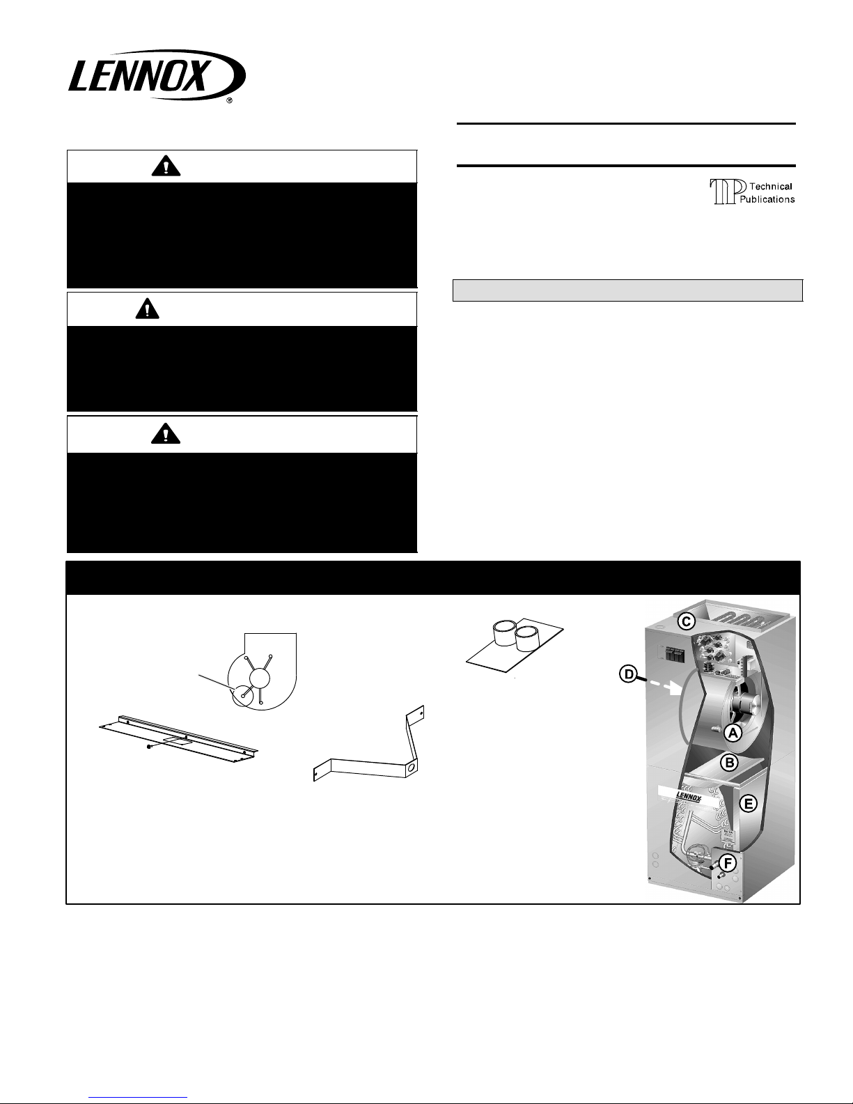
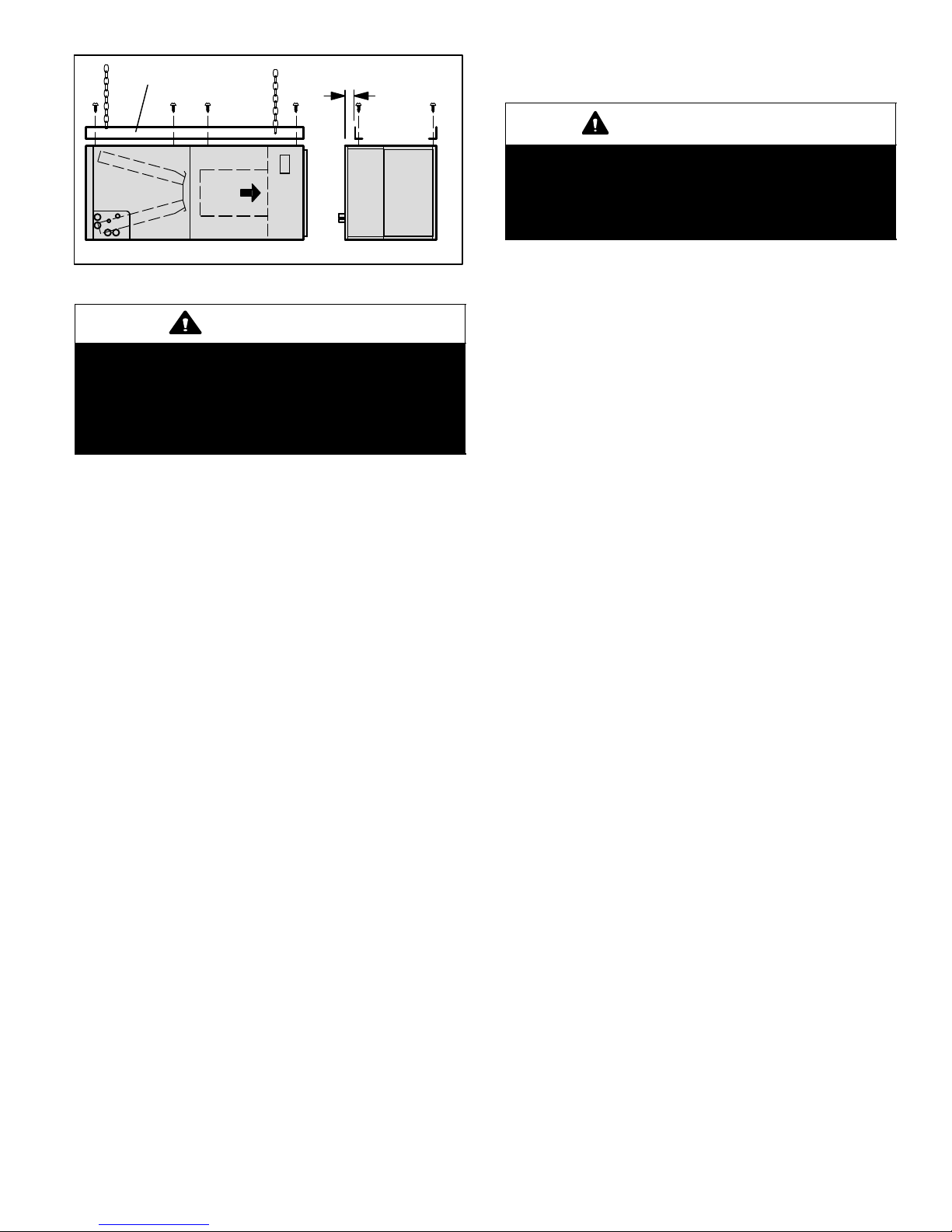
IMPORTANT INFORMATION TO INSTALLER
BLOWER MOTOR
SHIPPING BOLT
A
TOP CAP SHIPPING BRACKET (REPLACE
SCREWS IN TOP CAP AFTER REMOVAL)
C
REFRIGERANT LINE PLUGS [SEE
BRAZING CONNECTIONS ON PAGE 7]
CHECK FOR AND REMOVE THE FOLLOWING ITEMS BEFORE OPERATING UNIT.
BLOWER HOUSING SUPPORT PAD
B
BLOWER MOTOR SHIPPING
BRACKET
D
HORIZONTAL DRAIN PAN (SEE UPFLOW
APPLICATIONS ON PAGE 4 AND
DOWNFLOW APPLICATIONS ON PAGE 6)
E
F
05/09 506150−01
*2P0509* *P506150-01*
Page 1
Page 2
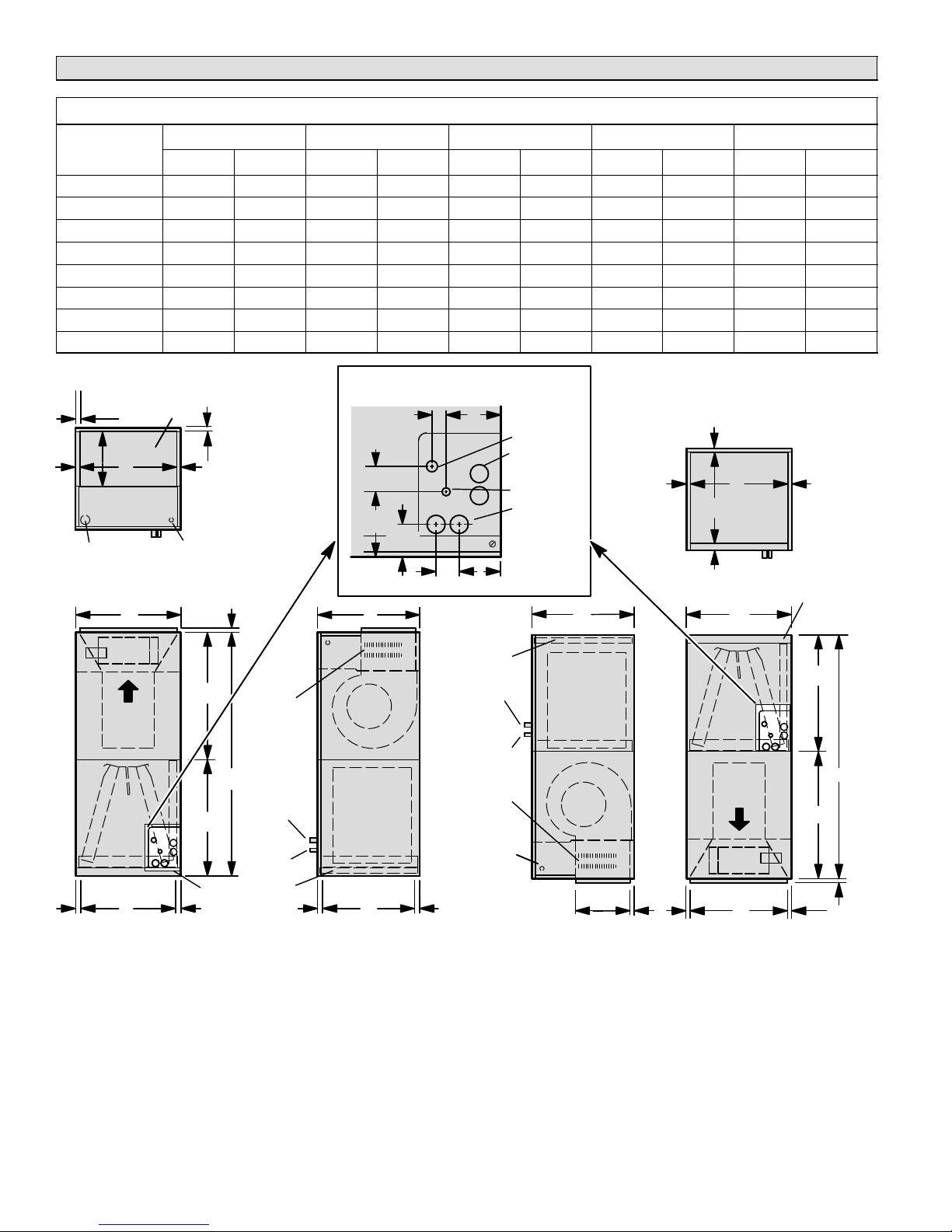
CBX32M Upflow and Downflow Unit Dimensions − Inches (mm)
CBX32M Model Dimensions (for Upflow, Downflow, LH and RH Horizontal Applications)
−018/−024 −030 −036 −042 −048/−060
Dimension
A 45−1/4 1149 49−1/4 1251 51 1295 52−1/2 1333 58-1/2 1486
B 16−1/4 413 21−1/4 540 21-1/4 540 21-1/4 540 21-1/4 540
C 20−5/8 524 20−5/8 524 22-5/8 575 22-5/8 575 24-5/8 625
D 14−3/4 375 19−3/4 502 19-3/4 502 19-3/4 502 19-3/4 502
E 19 483 19 483 21 533 21 533 23 584
F 15 381 20 508 20 508 20 508 20 508
G 24−5/8 625 24−5/8 625 26-3/8 670 27-7/8 708 27-7/8 708
H 20−5/8 524 24−5/8 625 24-5/8 625 24-5/8 625 30-5/8 778
inches mm inches mm inches mm inches mm inches mm
3/4
(19)
SUPPLY
AIR OPENING
D
11-1/16
(281)
LINE VOLTAGE
INLETS (TOP
AND LEFT SIDE)
Top View
3/4
(19)
LOW VOLTAGE
INLETS (TOP AND RIGHT
SIDE)
5/8
(16)
BC
Air Flow
G
OPTIONAL
ELECTRIC
HEAT
(FIELD−
INSTALLED)
A
SUCTION
H
Return Air
5/8
(16)
F
Front View Side View
5/8
(16)
FILTER
ACCESS
LINE
LIQUID
LINE
Upflow Position
(25)
2
2-3/4
(70)
PIPING PLATE DETAIL
1-3/4 (44)
4-3/8 (111)
SUCTION LINE
CONDENSATE
DRAINS (2)
(HORIZONTAL)
LIQUID LINE
CONDENSATE
DRAINS (2)
(UPFLOW AND
DOWNFLOW)
3-1/2 (89)
5/8
(16)
5/8 (16)
Air Opening
E
1 (25)
Top View
F
Return
5/8
(16)
FILTER
ACCESS
(FOR UPFLOW AND DOWNFLOW POSITIONS)
1-1/8 (29)
(51)
5-3/8
(137)
BC
FILTER
SUCTION
Blower
Coil
Return AirFILTER
1
E
5/8
(16)
LINE
LIQUID
LINE
OPTIONAL
ELECTRIC
HEAT (FIELD−
INSTALLED)
LOW VOLTAGE
(RIGHT SIDE)
LINE VOLTAGE
(LEFT SIDE)
11-1/16 (281)
Coil
5/8
(16)
Air Flow
Supply Air
D
Front ViewSide View
Blower
Supply Air
5/8
(16)
(KIT NUMBER 83M57 (LB−909844A) REQUIRED TO CONVERT
Downflow Position
UNIT TO DOWNFLOW APPLICATIONS.)
H
A
G
5/8 (16)
506150−01 05/09
Page 2
Page 3
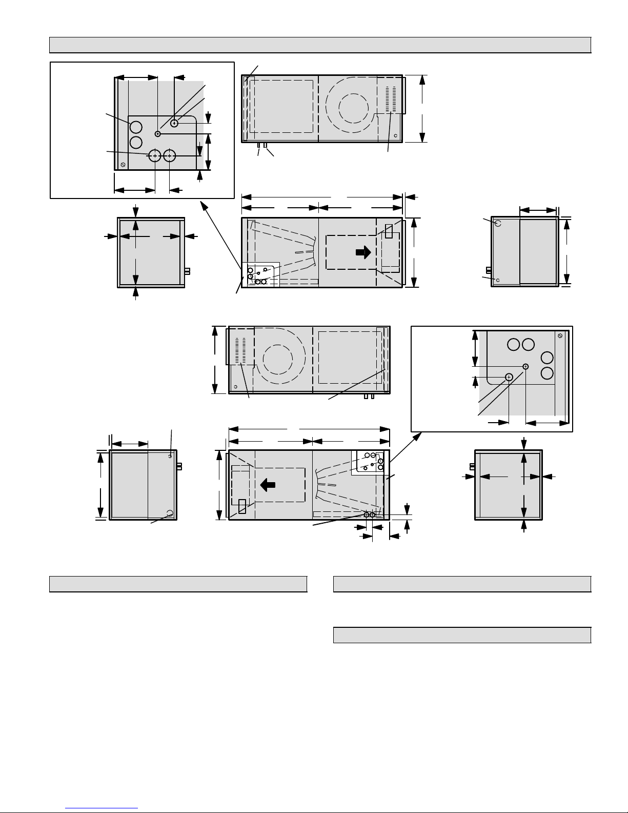
CBX32M Horizontal Left− and Right−Hand Unit Dimensions − Inches (mm)
Filter
LIQUID
LINE
FILTER ACCESS
Blower
Coil
SUCTION
LINE
H
Top View
A
Air
Flow
Front View
Blower
OPTIONAL ELECTRIC
HEAT (FIELD−INSTALLED)
G
Coil
C
5/8
(16)
B
INLETS (BOTTOM
PIPING PLATE
DETAIL
FOR DIMENSIONS A" THROUGH
LINE VOLTAGE
INLETS (TOP
AND RIGHT
SIDE)
LOW VOLTAGE
AND RIGHT
SIDE)
4-3/8
(111)
1-1/8
(29)
CONDENSATE
DRAINS (2)
(UPFLOW AND
DOWNFLOW)
CONDENSATE
DRAINS (2)
(HORIZONTAL)
PIPING PLATE
DETAIL
5/8
(16)
5/8
(16)
5/8
(16)
5-3/8
(137)
5-3/4
(46)
F
1-3/4
E
Return
Opening
Air
End View
(44)
(51)
2
(25)
1-1/2
(38)
1
LIQUID
LINE
SUCTION
LINE
1-1/8
(29)
4-3/8
(111)
Horizontal Position (Right-Hand Air Discharge)
C
H", SEE CHART ON PAGE 2.
11-1/16
(281)
Supply
Air
Opening
End View
3/4
(19)
3/4
(19)
D
3/4
(19)
OPTIONAL ELECTRIC
HEAT (FIELD INSTALLED)
5/8 (16)
B
CONDENSATE DRAINS (2)
A
G
Air Flow
(HORIZONTAL)
Front View
3/4
(19)
11-1/16
3/4
(19)
3/4
(19)
(281)
Supply
D
Air Opening
LINE VOLTAGE INLETS
(BOTTOM AND LEFT SIDE)
End View
LOW VOLTAGE
INLETS (TOP
AND LEFT SIDE)
Horizontal Position (Left-Hand Air Discharge)
General
The Lennox Elite® Series CBX32M air handler units are
designed for installation with a matched remote outdoor
unit that is charged with HFC−410A refrigerant and optional
field−installed electric heat. The air handler units are for
indoor installation only.
These instructions are intended as a general guide and do
not supersede local or national codes in any way. Consult
authorities having jurisdiction before installation. Check
equipment for shipping damage; if found, immediately
report damage to the last carrier.
FILTER
Top View
LINE
H
LIQUID
LINE
5-3/4
(146)
FILTER
ACCESS
1-1/2
(38)
SUCTION
LINE
LIQUID
LINE
1
(25)
Return
Air Opening
End View
2
5-3/8
(51)
(137)
5/8
(16)
E
5/8
F
(16)
5/8
(16)
SUCTION
1-3/4
(44)
Shipping and Packing List
Package 1 of 1 contains the following:
1Assembled air handler unit
Requirements
In addition to conforming to manufacturer’s installation
instructions and local municipal building codes, installation
of Lennox air handler units (with or without optional electric
heat), shall conform with the following National Fire
Protection Association (NFPA) standards:
S NFPA No. 90A − Standard for Installation of Air
Conditioning and Ventilation Systems
Page 3
CBX32M SERIES
Page 4
S NFPA No. 90B − Standard for Installation of Residence
Type Warm Air Heating and Air Conditioning Systems
This unit is approved for installation clearance to
combustible material as stated on the unit rating plate.
Accessibility and service clearances must take
precedence over combustible material clearances.
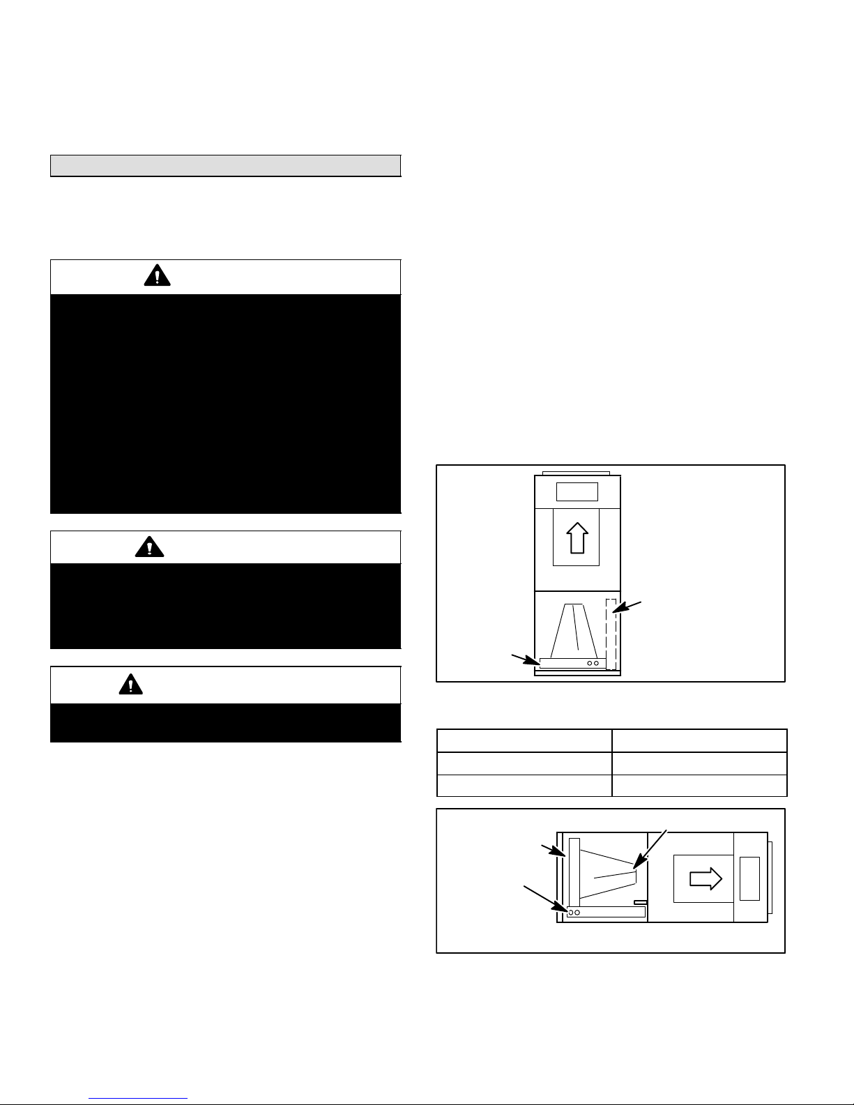
Installing the Unit
CBX32M units are factory−configured for upflow or
horizontal right−hand discharge installation. For downflow
or horizontal left−hand discharge, some field modification
is required.
WARNING
Electric Shock Hazard.
Can cause injury or death.
Foil-faced insulation has conductive
characteristics similar to metal. Be sure there are no
electrical connections within a ½" of the insulation.
If the foil-faced insulation comes in contact with
electrical voltage, the foil could provide a path for
current to pass through to the outer metal cabinet.
While the current produced may not be enough to
trip existing electrical safety devices (e.g. fuses or
circuit breakers), the current can be enough to
cause an electric shock hazard that could cause
personal injury or death.
To reassemble:
1. Align cabinet sections together.
2. Reinstall screws.
3. Replace blower and coil assemblies.
4. Replace access panel.
UPFLOW APPLICATION
Use the following procedures to configure the unit for
upflow operations:
1. Remove access panels. Remove corrugated padding
from the space between the blower and coil
assemblies.
2. The horizontal drain pan must be removed when the
coil blower is installed in the upflow position. Removing
horizontal drain pain will allow proper airflow and
increase efficiency.
3. Place unit in desired location. Make sure that unit is
level. Connect return and supply air plenums as
required using sheet metal screws as illustrated in
figure 1.
4. Install units which have no return air plenum on a
mounting stand that is at least 14" from the floor for
proper air return. Lennox offers an optional upflow unit
stand as listed in table 1.
WARNING
Improper installation, adjustment, alteration,
service or maintenance can cause property damage,
personal injury or loss of life. Installation and
service must be performed by a qualified installer or
service agency.
IMPORTANT
Kit number 83M57 (LB−109844A) must be installed
for downflow application.
DISASSEMBLE AND REASSEMBLE AIR HANDLER
UNIT
The CBX32M air handler unit consists of two sections
which are shipped assembled from the factory. If
necessary, the unit may be disassembled to facilitate
setting the unit. Follow the steps below:
To disassemble:
1. Remove access panels.
2. Remove both blower and coil assemblies. This will
lighten the cabinet for lifting.
3. Remove one screw from the left and right posts inside
the unit. Remove one screw from each side on the
back of the unit. Unit sections will now separate.
HORIZONTAL DRAIN PAN
(MUST BE REMOVED)
UPFLOW/
DOWNFLOW
DRAIN PAN
Figure 1. Upflow Configuration
Table 1. Optional Unit Side Stand (Upflow Only)
Model Kit Number
−018 and −024 45K31
−036, −042, −048 and −060 45K32
HORIZONTAL DRIP SHIELD
UPFLOW/
DOWNFLOW
DRAIN PAN
HORIZONTAL
DRAIN PAN
NO ADJUSTMENT IS NECESSARY
Figure 2. Right−Hand Discharge Configuration
506150−01 05/09
Page 4
Page 5
ANGLE IRON OR
SHEET METAL
FRONT VIEW
1/2 IN.
SCREWS
MAX.
ELECTRICAL INLET
CLEARANCE 4 IN. (102 MM)
END VIEW
Figure 3. Suspending Horizontal Unit
CAUTION
When removing the coil, there is possible danger of
equipment damage and personal injury. Be careful
when removing the coil assembly from a unit
installed in right− or left−hand applications. The coil
may tip into the drain pan once it is clear of the
cabinet. Support the coil when removing it.
HORIZONTAL RIGHT−HAND DISCHARGE
APPLICATION
Use the following procedures to configure the unit for
horizontal right−hand discharge operations:
NOTE − For horizontal applications, an secondary drain
pan is recommended. Refer to local codes.
1. Remove access panels. Remove corrugated padding
from the space between the blower and coil assembly.
2. No further adjustment is necessary. Set unit so that it is
sloped 1/4 inch toward the drain pan end of the unit as
illustrate in figure 2 on page 4.
3. If the unit is to be suspended, it must be supported
along the entire length of the cabinet as illustrated in
figure 3. If a strap is used, attach a piece of angle iron
or sheet metal to the unit (either above or below) so
that the full length of the cabinet is supported. Use
securing screws which are no longer than 1/2 inch to
avoid damaging the coil or filter. Connect the return
and supply air plenums as required using sheet metal
screws.
HORIZONTAL LEFT−HAND DISCHARGE
APPLICATION
Use the following procedures to configure the unit for
horizontal left−hand discharge operations:
NOTE − For horizontal applications, an secondary drain
pan is recommended. Refer to local codes.
Remove access panels. Remove corrugated padding from
the space between the blower and coil assembly before
operation.
1. Remove coil assembly from unit and remove the
horizontal drain pan as illustrated in figure 4, detail A
on page 6.
2. Remove drain plugs from back drain holes on
horizontal drain pan and reinstall them on front holes.
IMPORTANT
After removal of drain pan plug(s), check drain
hole(s) to verify that drain opening is fully open and
free of any debris. Also check to make sure that no
debris has fallen into the drain pan during installation that may plug up the drain opening.
3. Rotate the drain pan 180° front to back and install it on
the opposite side of coil.
4. Remove screws from top cap. Remove horizontal drip
shield screw located in the center of the back coil end
seal as illustrated in figure 4, details B and C on page
6.
5. Rotate horizontal drip shield 180° front to back.
6. Remove plastic plug from left hole on coil front end
seal and reinstall plug in back hole. Reinstall horizontal
drip shield screw in front coil end seal. Drip shield
should drain downward into horizontal drain pan inside
coil.
7. Rotate top cap 180° front to back and align with
unused screw holes. Holes must align with front and
back coil end plates. Note that top cap has a 45° bend
on one side and 90° bend on the other. The 90° bend
must be on the same side as the horizontal drain pan
as illustrated in figure 4 on page 6.
NOTE − Be very careful when you reinstall the screws into
coil end plate engaging holes. Misaligned screws may
damage the coil.
8. From the upflow position, flip cabinet 90° to the left and
set into place. Replace blower assembly. Secure coil
in place by bending down tab on cabinet support rail
as illustrated in figure 5 on page 6.
NOTE − For horizontal applications in high humidity
areas, seal around the exiting drain pipe, liquid line and
suction line to prevent infiltration of humid air.
9. Knock out drain seal plate from access door. Secure
plate to cabinet front flange with screw provided.
10. Flip access door and replace it on the unit.
11. Set unit so that it is sloped 1/4 inch toward the drain
pan end of the unit. Connect return and supply air
plenums as required using sheet metal screws.
12. If the unit is to be suspended, it must be supported
along the entire length of the cabinet as illustrated in
figure 3 on page 5. If using a chain or strap, attach a
piece of angle iron or sheet metal to the unit (either
above or below the unit), so that the full length of the
cabinet is supported. Use securing screws which are
no longer than 1/2 inch to avoid damaging the coil or
filter. Use sheet metal screws to connect the return
and supply air plenums.
Page 5
CBX32M SERIES
Page 6
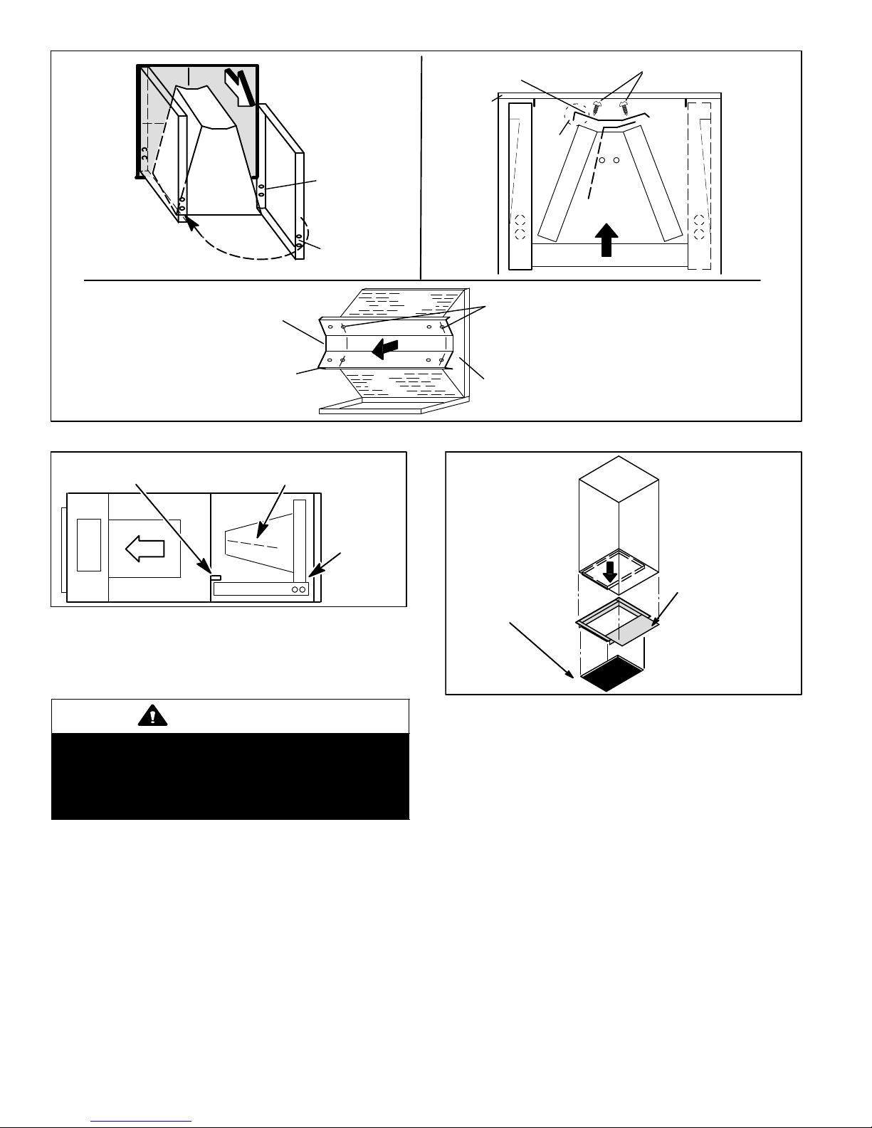
PLUGGED
END
OPEN END FOR
CONDENSATION
DRAIN
COIL
ASSEMBLY
COIL SHOWN IN UPFLOW
POSITION FOR EASY
CONVERSION
DETAIL A
(DRAIN PAN)
TOP CAP
90_
BEND
DRAIN PAN
ORIGINAL
PLUG
LOCATION
NEW PLUG
LOCATION
TOP CAP ROTATED TO
CORRECT POSITION
CABINET
SUPPORT
ALIGN HOLES WITH
HOLES IN COIL END
PLATE.
BACK COIL END SEAL
Figure 4. Left-Hand Discharge Modifications
BEND
DETAIL C
90_
TOP CAP
SCREWS
DETAIL B
(TOP CAP)
SECURING TAB ON
CABINET SUPPORT RAIL
HORIZONTAL DRIP SHIELD
HORIZONTAL
DRAIN PAN
Figure 5. Left−Hand Discharge Configuration
DOWNFLOW APPLICATION
Use the following procedures to configure the unit for
downflow operations:
WARNING
If electric heat section with circuit breakers (ECB29)
are applied to downflow CBX32M unit, circuit
breakers must be rotated 180_ to the UP position.
See ECB29 installation instructions for more
details.
NOTE − If downflow application is required, separately
order kit number 83M57 and install per kit’s instructions.
Also, use metal or class I supply and return air plenums.
On combustible flooring, use an additive base as
illustrated in figure 6. and use the following procedures:
AIR HANDLER
UNIT
COMBUSTIBLE FLOOR
PROPERLY−SIZED
FLOOR OPENING
ADDITIVE BASE
Figure 6. Combustible Flooring Additive Base
1. Cut an appropriately sized opening for combustible
base as illustrated figure 7.
2. Set the additive base into opening.
3. Connect supply air plenum to the additive base.
4. Set the unit on the additive base so flanges of the unit
drop into the base opening and seal against the
insulation strips. The unit is now locked in place.
5. Install return air plenum and secure with sheet metal
screws.
506150−01 05/09
Page 6
Page 7

11-3/8
1-5/8 (41)
15 (381)
CBX32M−21/26
and 31
CB30M−21/26
20 (508)
CBX32M−41 to −65
CB30M−31 to 65
1-5/8 (41)
5/8 (16)
(289)
1-5/8 (41)
SUPPLY
AIR
OPENING
TOP VIEW
22-1/8 (562)
13-3/8 (340)
OPENING
SIDE VIEW
inches
(mm)
18−1/4 (464)
CBX32M−21/26
and 31
CB30M−21/26
23−1/4 (591)
CBX32M−41 to −65
CB30M−31 to 65
2 (51)
Figure 7. Downflow Combustible Base Dimensions
If the homeowner reports water dripping from supply air
diffusers, check the shields and tape. Make sure the tape is
completely attached to the edges of the drip shield, and
that the drip shield is wedged firmly in place.
IMPORTANT
To prevent the build up of high levels of nitrogen
when purging, be sure it is done in a well ventilated
area. Purge low pressure nitrogen (1 to 2 psig)
through the refrigerant piping during brazing. This
will help to prevent oxidation and the introduction
of moisture into a system.
All coils are equipped with a factory−installed, internally
mounted check/expansion valve, which is suitable for use
in applications as follows:
S valve suitable for HCFC−22 use (CBX32M unit)
S valve suitable for HFC−410A use (CB30M unit)
The CBX32M/CB30M air handler’s coil line sizes are listed
in table 2. Use Lennox L15 (sweat) series line sets (refer to
the outdoor unit Engineering Handbook for proper size,
type and application). For field−fabricated refrigerant lines,
see the piping section of the Lennox Unit Information
Service Manual.
Brazing Connections
WARNING
Danger of explosion!
Can cause equipment damage, injury,
or death.
When using a high pressure gas such
as dry nitrogen to pressurize a
refrigeration or air conditioning
system, use a regulator that can
control the pressure down to 1 or 2 psig
(6.9 to 13.8 kPa).
AIR HANDLER UNIT
SUCTION LINE
LIQUID LINE
Figure 8. Brazing Connections
NOTE − CBX32M series evaporators use nitrogen or dry
air as a holding charge. If there is no pressure when the
rubber plugs are removed, check the coil or line set for
leaks before installing. After installation, pull a vacuum
on the line set and coil before releasing the unit charge
into the system.
Page 7
CBX32M SERIES
Page 8

ABOVE
FINISHED
SPACE?
NO
ALWAYS RUN AN OVERFLOW DRAIN LINE. IF NOT
POSSIBLE TO ROUTE OVERFLOW DRAIN LINE,
INSTALL FLOAT SWITCH. WIRE LOW VOLTAGE TO
SHUT DOWN COMPRESSOR PER INSTRUCTIONS.
AUXILIARY DRAIN LINE
EZ−TRAP®
EZT−226
CLEAN OUT
PRESS IN (DO
NOT GLUE)
VENT MUST
EXTEND ABOVE
HEIGHT OF COIL
DRAIN PAN BY TWO
INCHES (51MM)
VENT
DRAIN PAN
YES
SEC.
MAIN
OPTIONAL
SAFETY
PAN
WHEN A COIL IS LOCATED ABOVE FINISHED SPACE, A 3/4"
(19.1MM) OVERFLOW DRAIN LINE MUST BE INSTALLED AND
CONNECTED TO A SAFETY PAN OR TO THE SECONDARY
TRAPS MUST BE DEEP ENOUGH TO OFFSET MAXIMUM STATIC DIFFERENCES.
(GENERALLY, TWO INCHES (51MM) FOR NEGATIVE PRESSURE COILS (BLOWER
AFTER COIL) TRAPS ARE REQUIRED ON ALL DRAIN LINES CONNECTED TO COIL.
DRAIN OUTLET OF THE COIL.
ALTERNATE P−TRAP (49P66)
Figure 9. Typical Condensate Drain Connection
NOTE − See outdoor unit instructions on how to flow
nitrogen through line sets.
1. Remove access panel.
2. Remove the refrigerant line caps from the refrigerant
lines.
3. Use a wet rag to protect TXV sensing bulb (or remove
it) when brazing suction line connections.
4. Place a wet rag against piping plate and around the
suction line connection. The wet rag must be in place
to guard against damage to the paint.
5. With the wet rag in place, position a field provided
elbow fitting to the air handler’s suction line and line
set. Start nitrogen flow before brazing.
6. After the procedure is completed then remove the wet
rag.
7. Place wet rag against piping plate and around the
liquid line connection. Position liquid line elbow to air
handler’s suction line and to line set. Start nitrogen flow
and begin brazing both connections and after
procedure is completed then remove both wet rags.
8. Refer to instructions provided with outdoor unit for leak
testing, evacuating and charging procedures.
9. Install access panel.
1 X 3/4 X 3/4
REDUCING
TEE WITH
PLUG
J−TRAP
(91P90)
DRAIN LINE SHOULD SLOPE A MINIMUM OF
TO APPROVED DRAIN
ONE INCH PER 10 FEET (25MM PER 3
METERS)
Table 2. Refrigerant Line Sets
CBX32M
Units
−018/024 3/8 in
−030, −036 3/8 in
−042, −048 3/8 in
−060 3/8 in
Liquid
Line No.
(8 mm)
(10 mm)
(10 mm)
(10 mm)
Vapor/
Suction Line
5/8 in
(16 mm)
3/4 in.
(19 mm
7/8 in.
(22 mm)
1−1/8 in.
(29 mm)
L10
Line Sets
L10−26
20 ft. − 50 ft.
(6 m − 15 m)
L10−41
20 ft. − 50 ft.
(6 m − 15 m)
L10−65
30 ft. − 50 ft.
(9 m − 15 m)
Field
Fabricated
L15
Line Sets
L15−26
20 ft. − 50 ft.
(6 m − 15 m)
L15−41
20 ft. − 50 ft.
(6 m − 15 m)
L15−65
30 ft. − 50 ft.
(9 m − 15 m)
Field
Fabricated
Installing the Condensate Drain
Before connecting drain line(s), check drain hole(s) to
verify that drain opening is fully open and free of any
debris. Also check to make sure that no debris has fallen
into the drain pan during installation that may plug up the
drain opening.
Connect main condensate drain and route downward to an
open drain or sump. Do not connect drain to a closed waste
system. Refer to figure 9 on page 8 for typical condensate
trap configuration.
506150−01 05/09
Page 8
Page 9

It is recommended that the auxiliary drain be connected to
a drain line for all units. If auxiliary drain is not connected, it
must be plugged with provided cap. For downflow units,
the auxiliary drain shall be connected and routed to a drain.
See figure 10 for auxiliary and main drain locations.
The following practices are recommended to ensure
condensate removal as illustrated in figures 9 and 10:
S Drain piping should not be smaller than the drain
connections at drain pan.
S A trap must be installed in the main drain line.
S The trap must be deep enough to offset the difference
in static pressure between drain pan and atmosphere.
Generally, two inches is satisfactory for medium static
applications.
S Horizontal runs must be sloped 1 inch per 10 feet of
drain line to offset friction.
S An open vent in drain line will sometimes be required due
to line length, friction and static pressure.
S Drain construction and routing should facilitate future
cleaning and must not interfere with filter access.
S Auxiliary drain should run to an area where
homeowner will notice any drainage. The auxiliary
drain line does not required venting or a trap. Refer to
local codes.
Left−Hand
Discharge
Upflow or
Downflow
Right−Hand
Discharge
Reusable filters supplied with some units can be washed
with water and mild detergent. Some units are equipped
with standard throw−away type filters which should be
replaced when dirty.
To replace filter:
1. Loosen the thumbscrews holding the filter panel in
place.
2. Slide the filter out of the guides on either side of
cabinet.
3. Insert new filter.
4. Replace panel.
See table 3 for replacement filter sizes.
Table 3. Filter Dimension
Unit Model No. Filter Size Inches (mm)
−018 and −024 15 x 20 (381 x 508)
−030 20 x 20 (508 x 508)
−036 and −042 20 x 22 (508 x 559)
−048 and −060 20 x 24 (508 x 610)
Making Electrical Connections
WARNING
USE COPPER CONDUCTORS ONLY.
Run 24V Class II wiring only through specified low
voltage opening. Run line voltage wiring only
through specified high voltage opening. Do not
combine voltage in one opening.
Auxiliary Drain on Left
Main Drain on Right
Figure 10. Drain Locations
Inspecting and Replacing Filters
IMPORTANT
Filter access panel must be in place during unit
operation. Excessive warm air entering the unit may
result in water blow−off problems.
Each unit includes a factory−installed filter. Note that filter
access door fits over access panel. Air leakage will occur if
access panel is placed over filter door.
Filters should be inspected monthly and must be cleaned
or replaced when dirty to assure proper furnace operation.
Wiring must conform to the current National Electric Code
ANSI/NFPA No. 70, or Canadian Electric Code Part I, CSA
Standard C22.1, and local building codes. Refer to
following wiring diagrams. See unit nameplate for
minimum circuit ampacity and maximum overcurrent
protection size.
Select the proper supply circuit conductors in
accordance with tables 310−16 and 310−17 in the
National Electric Code, ANSI/NFPA No. 70 or tables 1
through 4 in the Canadian Electric Code, Part I, CSA
Standard C22.1.
This unit is provided with knockouts for conduit. Refer to
figure 15 for unit schematic wiring diagram. Refer to
figures 14 through 13 for typical field wiring.
Separate openings have been provided for 24V low
voltage and line voltage. Refer to the dimension illustration
for specific location.
Page 9
CBX32M SERIES
Page 10

CIRCUIT 1
CIRCUIT BREAKERS
OR TERMINAL BLOCK
Figure 11. Typical Field Wiring − Cooling Application with Electric Heat
4
7
CB1
CIRCUIT
BREAKER
OR
FUSE
NOTE − USE COPPER CONDUCTORS ONLY.
REFER TO UNIT RATING PLATE FOR MINIMUM
6
1
3
CIRCUIT AMPACITY AND MAXIMUM OVERCURRENT PROTECTION SIZE.
LINE VOLTAGE FIELD INSTALLED
CLASS 2 VOLTAGE FIELD INSTALLED
NEC/CEC
9
NOTE − ALL REMAINING WIRES ARE FACTORY
INSTALLED
TO EXTERNAL LOAD 24VAC AT .50 AMP MAXIMUM.
THERMOSTAT HEAT ANTICIPATION SETTING 0.4
AMP ELECTRIC HEAT
WHEN TWO−STAGE THERMOSTAT IS USED,
CONNECT SECOND STAGE HEAT BULB TO TERMINAL W2" AND REMOVE JUMPER BETWEEN
TERMINALS R" AND W2."
FACTORY INSTALLED JUMPERS
L3 CONNECTION USED ON (Y−VOLTAGE)
3−PHASE ELECTRIC HEATERS ONLY.
CIRCUIT 1
CIRCUIT BREAKERS
OR TERMINAL BLOCK
CB1
CIRCUIT
BREAKER
OR FUSE
LINE VOLTAGE FIELD INSTALLED
4
7
6
1
3
9
2
NOTE − ALL REMAINING WIRES ARE FACTORY INSTALLED
TO EXTERNAL LOAD 24VAC AT .50 AMP MAXIMUM
FACTORY INSTALLED JUMPERS
Y2 USED ONLY WHEN TWO SPEED COMPRESSOR IS USED (HP21).
USING SERVICE LIGHT OPTION (S54) WITH SOME ELECTRONIC
THERMOSTATS MAY REQUIRE MOVING S54 COMMON WIRE TO Y1
IN HEAT PUMP UNIT.
COMMON USED ONLY ON SOME THERMOSTATS.
AMBIENT COMPENSATING THERMISTOR CONNECTION USED ONLY
ON SOME THERMOSTATS.
CLASS 2 VOLTAGE FIELD INSTALLED NEC/CEC
E C W1 G O Y1 R L T
5
W1 O Y1 R
L
1
Y2
3
T
Y2
C
COMMON
ELECTRIC HEAT
REVERSING VALVE
HEAT PUMP CLASS 2
VOLTAGE TERMINALS
POWER
COMPRESSOR
THERMISTOR
SERVICE LIGHT
6
4
2ND STAGE COMPRESSOR
Figure 12. Typical Field Wiring − Heat Pump Only Application
506150−01 05/09
Page 10
Page 11

CIRCUIT 1
CIRCUIT BREAKERS
OR TERMINAL BLOCK
LINE VOLTAGE FIELD
INSTALLED
CLASS 2 VOLTAGE FIELD
INSTALLED NEC/CEC
NOTE − ALL REMAINING WIRES
ARE FACTORY INSTALLED
THERMOSTAT HEAT ANTICIPATION
SETTING 0.4 AMP ELECTRIC HEAT
FACTORY INSTALLED JUMPERS
WHEN OUTDOOR THERMOSTAT IS
USED, CONNECT LEADS TO
TERMINALS R" AND W2" AND
REMOVE JUMPER BETWEEN
TERMINALS R’ AND W2."
EMERGENCY HEAT RELAY (USED
ONLY IF OUTDOOR T’STAT IS
USED) FIELD PROVIDED AND
INSTALLED NEW INDOOR UNIT.
24VAC 5VA MAX NEC/CEC CLASS 2
4
6
1
3
9
7
CB1
CIRCUIT
BREAKER
OR FUSE
USING SERVICE LIGHT OPTION (S54) WITH SOME ELECTRONIC
THERMOSTATS MAY REQUIRE MOVING S54 COMMON WIRE TO Y1 IN
HEAT PUMP UNIT.
COMMON USED ONLY ON SOME THERMOSTATS.
Y2 USED ONLY WHEN TWO-SPEED COMPRESSOR IS USED (HP21)
AMBIENT COMPENSATING THERMISTOR CONNECTION USED ONLY ON
SOME THERMOSTATS.
S23
K22
HEAT PUMP CLASS 2
VOLTAGE TERMINALS
6
ECW1GOY1RL
C
COMMON
W1
O
ELECTRIC HEAT
REVERSING VALVE
RL
Y1
POWER
COMPRESSOR
SERVICE LIGHT
Y2
T
T
Y2
THERMISTOR
2ND STAGE COMPRESSOR
8
7
CIRCUIT 1
Figure 13. Typical Field Wiring − Heat Pump Application with Electric Heat
(Black)
(Orange)
FIELD−SUPPLIED WIRE NUTS
4
7
CB1 CIRCUIT BREAKER OR
FUSE
NOTE − USE COPPER CONDUCTORS ONLY.
6
1
3
REFER TO UNIT RATING PLATE FOR MINIMUM
CIRCUIT AMPACITY AND MAXIMUM OVERCURRENT PROTECTION SIZE.
LINE VOLTAGE FIELD INSTALLED
9
CLASS 2 VOLTAGE FIELD INSTALLED
NEC/CEC
NOTE − ALL REMAINING WIRES ARE FACTORY
INSTALLED
TO EXTERNAL LOAD 24VAC AT .50 AMP MAXIMUM.
FACTORY INSTALLED JUMPERS
Figure 14. Typical Field Wiring − Cooling Only Application
Page 11
CBX32M SERIES
Page 12

506150−01 05/09
Figure 15. Typical Wiring Diagram − Single Phase
Page 12
Page 13

Figure 16. Typical Wiring Diagram − Three Phase
Page 13
CBX32M SERIES
Page 14

Sealing the Unit
units with electric heat, refer to the ECB29 installation
instructions.
WARNING
There must be an airtight seal between the bottom
of the air handler and the return air plenum. Use
fiberglass sealing strips, caulking, or equivalent
sealing method between the plenum and the air
handler cabinet to ensure a tight seal. Return air
must not be drawn from a room where this air
AIR VOLUME ADJUSTMENT
Blower speed selection is accomplished by changing the
taps at the harness connector at the Blower motor as
illustrated in figure 17. Refer to unit wiring diagram in figure
15 on page 12. Refer to tables 4 through 11 for air handler
performance data.
handler or any gas−fueled appliance (i.e., water
heater), or carbon monoxide−producing device (i.e.,
wood fireplace) is installed.
HARNESS
CONNECTOR
Seal the unit so that warm air is not allowed into the
cabinet. Warm air introduces moisture, which results in
water blow−off problems. This is especially important when
the unit is installed in an unconditioned area.
Make sure the liquid line and suction line entry points are
sealed with either the provided flexible elastomeric thermal
insulation, or field provided material (e.g. Armaflex,
Permagum or equivalent). Any of the previously mention
materials may be used to seal around the main and
auxiliary drains, and around open areas of electrical inlets.
Adjusting the Blower Speed Adjustments
PRESS THE TAB TO RELEASE WIRE CONNECTOR.
SELECT CONNECTOR LOCATION FOR NEW SPEED.
MINIMUM BLOWER SPEEDS (WITH ELECTRIC
HEATERS)
For the minimum allowable speed for the CBX32M series
Table 4. CBX32M-018/024 Air Handler Performance (208/230V)
External Static
Pressure
in. w.g. Pa cfm L/s Watts cfm L/s Watts cfm L/s Watts
.00 0 700 330 245 895 425 300 1030 485 365
.05 10 695 330 245 890 420 295 1015 480 360
.10 25 690 325 240 875 415 290 1000 470 355
.15 35 680 320 235 860 405 285 980 465 345
.20 50 665 315 230 845 400 280 960 455 340
.25 60 650 310 220 825 390 275 935 440 335
.30 75 635 300 215 800 380 265 910 430 325
.40 100 590 280 205 745 355 250 850 400 310
.50 125 535 255 190 685 320 235 780 370 295
.60 150 470 220 175 605 285 220 705 330 280
.70 175 395 185 165 520 245 200 615 290 265
.75 185 350 165 155 475 225 195 565 265 255
NOTE − All air data is measured external to unit with air filter in place. Electric heaters have no appreciable air resistance.
Low Medium High
Air Volume and Motor Watts at Specific Blower Taps
INSERT WIRE UNTIL IT CLICKS.
Figure 17. Blower Speed Tap Selection
506150−01 05/09
Page 14
Page 15

Table 5. CBX32M-030 Air Handler Performance (208/230V)
Air Volume and Motor Watts at Specific Blower Taps
External Static Pressure
Low High
in. w.g. Pa cfm L/s Watts cfm L/s Watts
.00 0 1120 530 390 1525 720 505
.05 10 1150 540 385 1520 720 495
.10 25 1170 550 380 1510 715 480
.15 35 1180 560 285 1495 705 470
.20 50 1190 560 280 1475 695 455
.25 60 1185 560 275 1450 685 440
.30 75 1175 555 375 1415 670 430
.40 100 1135 535 325 1335 630 400
.50 125 1060 500 300 1230 580 375
.60 150 960 455 280 1100 520 345
.70 175 830 390 255 950 450 320
.75 185 750 355 245 870 410 305
NOTE − All air data is measured external to unit with air filter in place. Electric heaters have no appreciable air resistance.
Table 6. CBX32M-036 Air Handler Performance (208/230V)
External Static
Pressure
Low Medium High
in. w.g. Pa cfm L/s Watts cfm L/s Watts cfm L/s Watts
.00 0 915 430 335 1120 530 390 1525 720 505
.05 10 965 455 330 1150 540 385 1520 720 495
.10 25 1005 475 315 1170 550 380 1510 715 480
.15 35 1035 490 235 1180 560 285 1495 705 470
.20 50 1055 495 230 1190 560 280 1475 695 455
.25 60 1060 500 220 1185 560 275 1450 685 440
.30 75 1050 495 215 1175 555 375 1415 670 430
.40 100 1005 475 290 1135 535 325 1335 630 400
.50 125 915 430 255 1060 500 300 1230 580 375
.60 150 775 365 230 960 455 280 1100 520 345
.70 175 590 280 205 830 390 255 950 450 320
.75 185 485 230 195 750 355 245 870 410 305
NOTE − All air data is measured external to unit with air filter in place. Electric heaters have no appreciable air resistance.
Air Volume and Motor Watts at Specific Blower Taps
Table 7. CBX32M−036 Air Handler Performance (460V − 1 ph)
Air Volume and Motor Watts at Specific Blower Taps
External Static Pressure
in. w.g. Pa cfm L/s Watts cfm L/s Watts cfm L/s Watts
.00 0 955 450 425 1130 535 530 1460 690 665
.05 10 950 450 415 1120 530 520 1445 680 650
.10 25 945 445 410 1115 525 510 1435 675 640
.15 35 940 445 400 1110 525 500 1415 670 630
.20 50 935 440 390 1105 520 490 1400 660 615
.25 60 930 440 385 1100 520 485 1380 650 600
.30 75 920 435 375 1090 515 475 1360 645 585
.40 100 910 430 360 1075 510 455 1325 625 555
.50 125 895 420 345 1060 500 435 1280 605 520
.60 150 880 415 330 1035 490 410 1225 580 480
.70 175 855 405 315 - - - - - - - - - - - - 1145 540 430
NOTE − All air data is measured external to unit with air filter in place. Electric heaters have no appreciable air resistance.
Low Medium High
Page 15
CBX32M SERIES
Page 16

Table 8. CBX32M-042 Air Handler Performance (208/230V)
External Static
Pressure
Low Medium High
in. w.g. Pa cfm L/s Watts cfm L/s Watts cfm L/s Watts
.00 0 1325 625 370 1600 755 455 1825 860 565
.05 10 1335 630 370 1585 750 455 1790 845 555
.10 25 1335 630 370 1565 740 450 1750 825 540
.15 35 1330 630 365 1540 725 440 1710 805 530
.20 50 1320 620 360 1505 710 435 1660 785 520
.25 60 1300 615 355 1470 695 425 1610 760 505
.30 75 1270 600 350 1425 675 415 1555 735 495
.40 100 1195 565 330 1320 625 390 1430 675 465
.50 125 1090 515 310 1195 565 365 1290 610 440
.60 150 955 450 285 1050 495 335 1135 535 415
.70 175 795 375 260 875 415 310 965 455 385
.75 185 700 330 250 780 370 295 875 415 370
NOTE − All air data is measured external to unit with air filter in place. Electric heaters have no appreciable air resistance.
Air Volume and Motor Watts at Specific Blower Taps
Table 9. CBX32M-048 Air Handler Performance (208/230V)
External Static
Pressure
Low Medium High
in. w.g. Pa cfm L/s Watts cfm L/s Watts cfm L/s Watts
.00 0 1475 695 430 1785 845 520 1910 900 590
.05 10 1480 700 430 1770 835 515 1895 895 585
.10 25 1475 695 425 1750 825 510 1870 880 580
.15 35 1465 690 420 1720 810 500 1840 865 570
.20 50 1445 680 410 1685 795 490 1800 850 565
.25 60 1415 670 405 1645 775 480 1755 830 550
.30 75 1380 650 395 1600 755 465 1700 805 540
.40 100 1290 610 370 1485 700 440 1580 745 515
.50 125 1170 550 345 1350 635 410 1425 675 485
.60 150 1020 480 320 1190 560 380 1250 590 450
.70 175 840 395 295 1000 470 350 1045 495 415
.75 185 740 350 280 900 425 335 930 440 400
NOTE − All air data is measured external to unit with air filter in place. Electric heaters have no appreciable air resistance.
Air Volume and Motor Watts at Specific Blower Taps
506150−01 05/09
Page 16
Page 17

Table 10. CBX32M−048 Air Handler Performance (460V − 1 ph)
Air Volume and Motor Watts at Specific Blower Taps
External Static Pressure
Low High
in. w.g. Pa cfm L/s Watts cfm L/s Watts
.00 0 1775 835 530 1870 885 610
.05 10 1775 835 530 1875 885 610
.10 25 1765 835 515 1870 880 590
.15 35 1750 825 510 1850 875 585
.20 50 1720 815 500 1825 860 575
.25 60 1685 795 490 1790 845 560
.30 75 1645 775 480 1745 825 545
.40 100 1530 720 450 1625 765 505
.50 125 1380 650 420 1465 690 470
.60 150 1195 565 385 1270 600 425
.70 175 975 460 350 1030 485 385
.80 200 720 340 320 755 355 340
NOTE − All air data is measured external to unit with air filter in place. Electric heaters have no appreciable air resistance.
Table 11. CBX32M-060 Air Handler Performance (208/230V)
External Static
Pressure
Low Medium High
in. w.g. Pa cfm L/s Watts cfm L/s Watts cfm L/s Watts
.00 0 1775 835 585 2025 955 670 2115 995 780
.05 10 1775 835 590 2010 950 665 2100 990 770
.10 25 1770 835 580 1995 940 655 2085 985 765
.15 35 1760 830 570 1975 930 645 2060 970 750
.20 50 1745 825 560 1950 920 635 2030 960 740
.25 60 1725 815 550 1915 905 625 2000 945 730
.30 75 1695 800 535 1880 885 610 1960 925 715
.40 100 1630 770 505 1795 845 580 1870 880 685
.50 125 1540 725 475 1690 795 545 1755 830 655
.60 150 1425 675 440 1560 735 515 1620 765 625
.70 175 1295 610 410 1415 670 480 1465 690 590
.80 200 1140 535 375 1250 590 445 1290 610 560
.85 210 1050 495 360 1160 550 425 1195 565 545
NOTE − All air data is measured external to unit with air filter in place. Electric heaters have no appreciable air resistance.
Air Volume and Motor Watts at Specific Blower Taps
Table 12. CBX32M−60 Air Handler Performance (460V − 1 ph)
External Static Pressure
in. w.g. Pa cfm L/s Watts cfm L/s Watts
.00 0 1965 930 710 2140 1010 795
.05 10 1950 920 700 2110 995 780
.10 25 1930 910 685 2080 980 765
.15 35 1910 900 675 2045 965 755
.20 50 1880 890 660 2005 945 740
.25 60 1850 875 645 1965 925 725
.30 75 1815 855 630 1920 905 710
.40 100 1735 820 600 1820 860 680
.50 125 1635 770 570 1710 805 650
.60 150 1520 720 540 1585 750 615
.70 175 1390 655 505 1450 685 585
.80 200 1245 590 475 1305 615 550
.85 210 1165 550 460 1225 580 535
NOTE − All air data is measured external to unit with air filter in place. Electric heaters have no appreciable air resistance.
Air Volume and Motor Watts at Specific Blower Taps
Low High
Page 17
CBX32M SERIES
Page 18

Repairing or Replacing Cabinet Insulation
IMPORTANT
DAMAGED INSULATION MUST BE REPAIRED OR
REPLACED before the unit is put back into
operation. Insulation loses its insulating value
when wet, damaged, separated or torn.
GLUE − Make sure there is
full coverage of glue on the
metal or insulation so there
are no areas where air
pockets may form which
can lead to sweating.
Matt- or foil−faced insulation is installed in indoor
equipment to provide a barrier between outside air
conditions (surrounding ambient temperature and
humidity) and the varying conditions inside the unit. If the
insulation barrier is damaged (wet, ripped, torn or
separated from the cabinet walls), the surrounding
ambient air will affect the inside surface temperature of the
cabinet. The temperature/humidity difference between the
inside and outside of the cabinet can cause condensation
on the inside or outside of the cabinet which leads to sheet
metal corrosion and subsequently, component failure.
REPAIRING DAMAGED INSULATION
Areas of condensation on the cabinet surface are an
indication that the insulation is in need of repair.
If the insulation in need of repair is otherwise in good
condition, the insulation should be cut in an X pattern,
peeled open, glued with an appropriate all−purpose glue
and placed back against the cabinet surface, being careful
to not overly compress the insulation so the insulation can
retain its original thickness. If such repair is not possible,
replace the insulation. If using foil-faced insulation, any
cut, tear, or separations in the insulation surface must be
taped with a similar foil−faced tape.
1. CUT INSULATION IN X PATTERN
2. APPLY GLUE
3. PRESS GLUED TABS AGAINST CABINET
Figure 18. Repairing Insulation
WARNING
This product and/or the indoor unit it is matched
with may contain fiberglass wool.
Disturbing the insulation during installation,
maintenance, or repair will expose you to fiberglass
wool dust. Breathing this may cause lung cancer.
(Fiberglass wool is known to the State of California
to cause cancer.)
Fiberglass wool may also cause respiratory, skin,
and eye irritation.
To reduce exposure to this substance or for further
information, consult material safety data sheets
available from address shown below, or contact
your supervisor.
Lennox Industries Inc.
P.O. Box 799900
Dallas, TX 75379−9900
506150−01 05/09
Page 18
 Loading...