

Page 1
©2019 Lennox Industries Inc.
Dallas, Texas, USA
INSTALLATION
INSTRUCTIONS
THIS MANUAL MUST BE LEFT WITH THE
HOMEOWNER FOR FUTURE REFERENCE
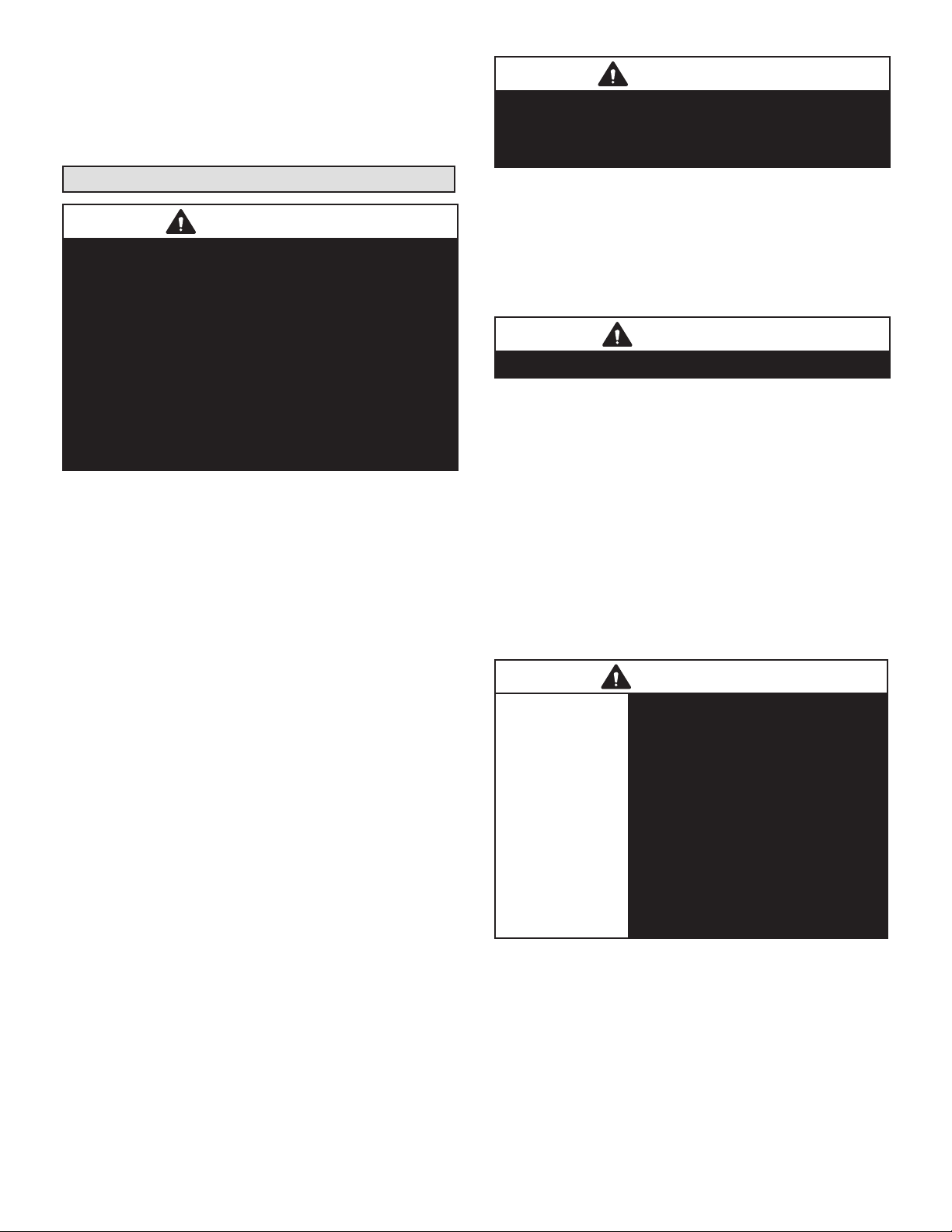
WARNING
Improper installation, adjustment, alteration, service
or maintenance can cause property damage, personal
injury or loss of life. Installation and service must be
performed by a licensed professional HVAC installer or
equivalent, service agency, or the gas supplier.
IMPORTANT
The Clean Air Act of 1990 bans the intentional venting of
refrigerant (CFCs, HCFCs and HFCs) as of July 1, 1992.
Approved methods of recovery, recycling or reclaiming
must be followed. Fines and/or incarceration may be
levied for noncompliance.
NOTICE
A thermostat is not included and must be ordered
separately.
• A Lennox communicating thermostat must be used in
communicating applications.
• In non-communicating applications, the Lennox
ComfortSense® thermostat may be used, as well as
other non-communicating thermostats.
In all cases, setup is critical to ensure proper system
operation.
Field wiring for both communicating and noncommunicating applications is illustrated in diagrams,
which begin on page 13.
IMPORTANT: Special procedures are required for cleaning the all-aluminum coil in this unit. See page 43 in this instruction
for information.
Dave Lennox Signature®
Collection CBA38MV Units
MULTI-POSITION AIR HANDLERS
507725-02
12/2019
Table of Contents
CBA38MV Upow and Downow Unit Dimensions ....... 2
CBA38MV Horiz. LH/RH Discharge Unit Dimensions ...3
General Information ....................................................... 4
Shipping and Packing List .............................................4
Installation Clearances ..................................................4
Requirements ................................................................5
Installing the Unit ........................................................... 5
Brazing Connections .....................................................9
Installing the Condensate Drain .................................. 11
Inspecting and Replacing Filters .................................12
Sealing the Unit ...........................................................12
Field Control Wiring ..................................................... 13
Air Handler Control Button, Display and Jumpers ....... 25
Target CFM Tables ......................................................30
Unit Operating Sequences ..........................................32
Unit Operating Sequences ..........................................34
Heat Pump Operation (Heating and Cooling) .............. 39
Cooling Operation ........................................................40
Error Code / Recall Mode ............................................ 41
Indoor Blower Test ....................................................... 42
Operation ..................................................................... 42
Repairing or Replacing Cabinet Insulation .................. 43
Homeowner Maintenance ............................................43
Professional Maintenance ...........................................43
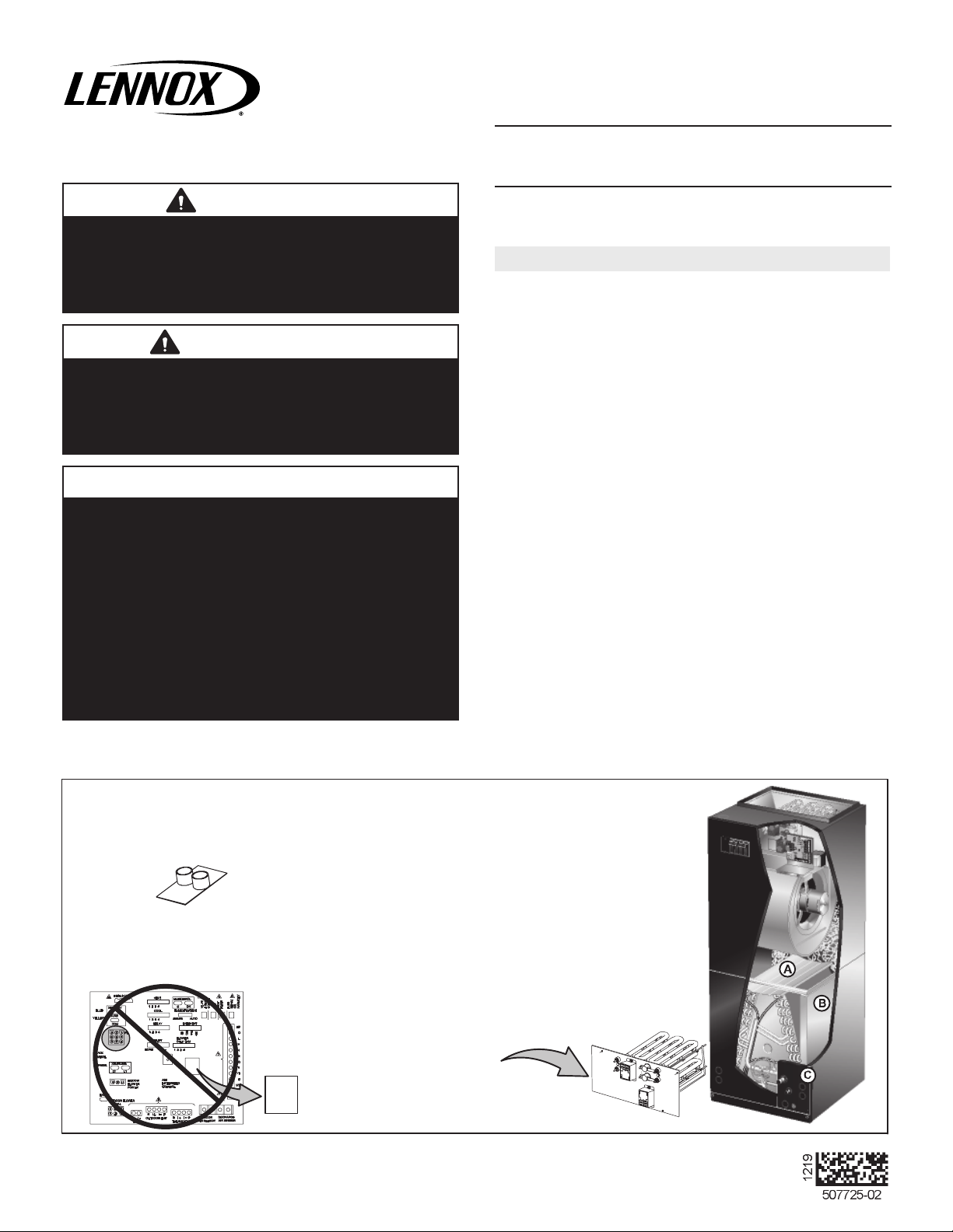
IMPORTANT INFORMATION FOR INSTALLER
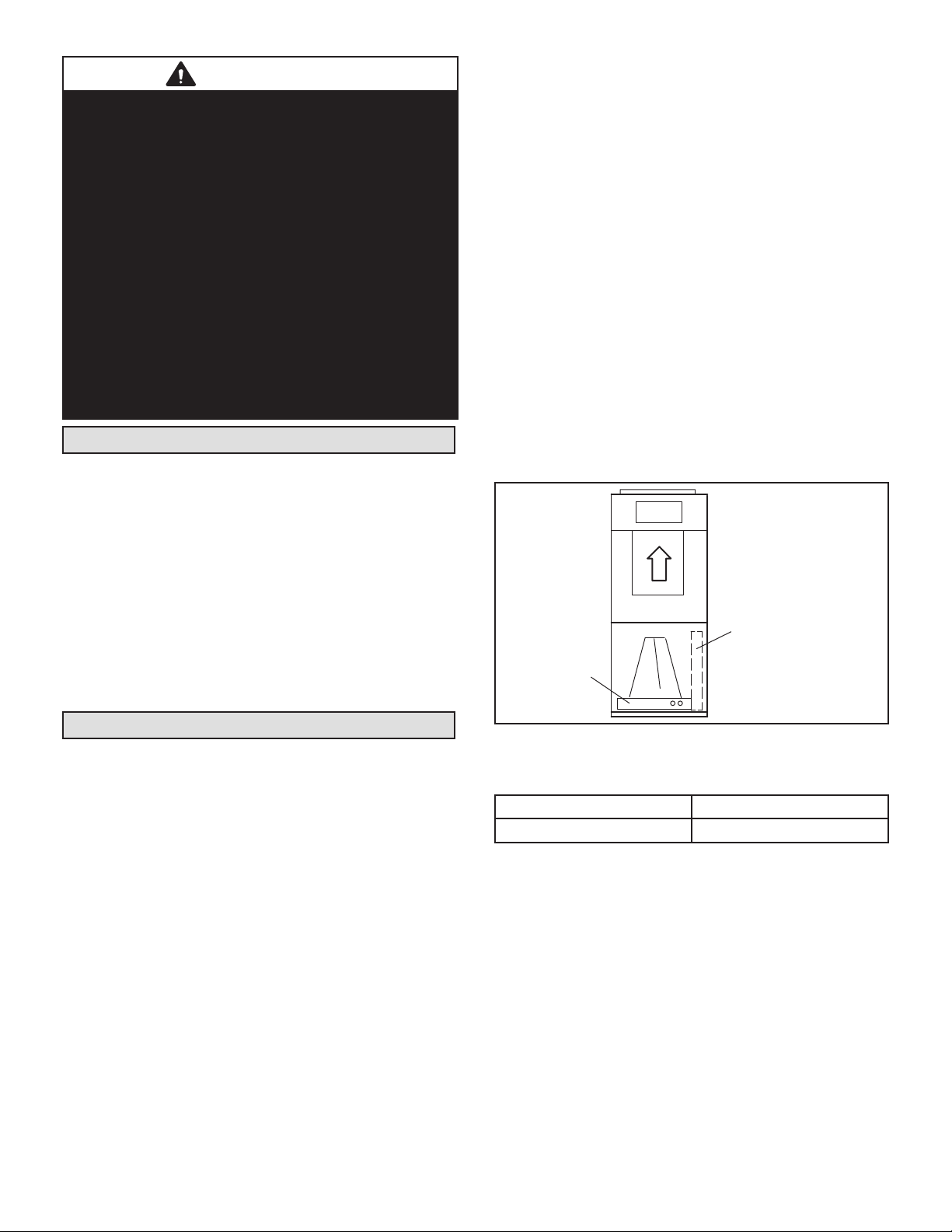
CHECK FOR AND REMOVE THE FOLLOWING ITEMS BEFORE OPERATING UNIT.
BLOWER HOUSING SUPPORT PAD.
A
Important Update: The CBA38MV Air Handler Control (AHC) has been enhanced to
automatically configure (set-up) the electric heat when the ECBA38 electric heat harness
is connected to CBA38MV air handler. Manual Configuration of the electric heat using
the push button is no longer required. See page 32.
H
HORIZONTA L DRAIN PA N (SEE
B
UPFLOW APPLICATIONS ON PAGE
5 AND DOWNFLOW APPLICATIONS
ON PAGE 8 )
CONFIGURE ELECTRIC HEAT
REFRIGERANT LINE PLUGS (SEE
C
BRAZING CONNECTION ON PAGE 9) .
H
ECB38
Page 1
Page 2
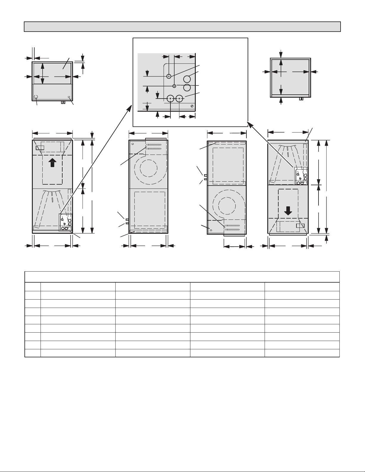
CBA38MV Upow and Downow Unit Dimensions – Inches (mm)
3/4 (19)
11‐1/16 (281)
LINE VOLTAGE
INLETS (TOP
AND LEFT SIDE)
TOP VIEW
FLOW
RETURN AIR
FRONT VIEW
SUPPLY AIR
D
AIR
F
OPENING
LOW VOLTAGE
INLETS (TOP AND
RIGHT SIDE)
5/8 (16)
3/4 (19)
5/8 (16)
G
ELECTRIC HEAT
(FIELD-INSTALLED)
A
H
FILTER ACCESS
UP-FLOW POSITION
OPTIONAL
SUCTION
LINE
LIQUID
LINE
FILTER
2
2‐3/4
(70)
PIPING PLAT E DETAIL
1‐3/4 (44)
4‐3/8 (111)
3‐1/2 (89)
(FOR UP-FLOW AND DOWN-FLOW POSITIONS)
1‐1/8 (29)
(51)
5‐3/8
(137)
CB
FILTER
SUCTION
BLOWER
COIL
RETURN AIR
)52( 1)61( 8/5
SIDE VIEW
E
5/8 (16)
LINE
LIQUID
LINE
OPTIONAL
ELECTRIC HEAT
(FIELD-INSTALLED)
LOW VOLTAGE
(RIGHT SIDE)
LINE VOLTAGE
(LEFT SIDE)
SUCTION LINE
CONDENSATE DRAINS
(2) (HORIZONTAL)
LIQUID LINE
CONDENSATE DRAINS
(2) (UP-FLOW AND
DOWN-FLOW)
C
COIL
BLOWER
SUPPLY
11‐1/16 (281)
AIR
SIDE VIEW
5/8 (16)
5/8 (16)
5/8 (16)
DOWN-FLOW POSITION
5/8 (16)
F
Air Opening
E
1 (25)
TOP VIEW
B
AIR FLOW
SUPPLY AIR
D
FRONT VIEW
5/8 (16)
Return
FILTER ACCESS
H
A
G
5/8 (16)
CBA38MV Common Dimensions - Inches (mm)
Dim. -018/024 -030/-036 -042/-048 -060
A
B
C
D
E
F
G
H
49-1/4 (1251) 51 (1295) 58-1/2 (1486) 62‐1/2 (1588)
21-1/4 (540) 21-1/4 (540) 21‐1/4 (540) 21‐1/4 (540)
20-5/8 (524) 22‐5/8 (575) 24-5/8 (625) 24-5/8 (625)
19-3/4 (502) 19-3/4 (502) 19‐3/4 (502) 19‐3/4 (502)
19 (483) 21 (533) 23 (584) 23 (584)
20 (508) 20 (508) 20 (508) 20 (508)
24-5/8 (625) 26‐3/8 (670) 27‐7/8 (708) 27‐7/8 (708)
24-5/8 (625) 24-5/8 (625) 30-5/8 (778) 34‐5/8 (879)
Page 2
Page 3
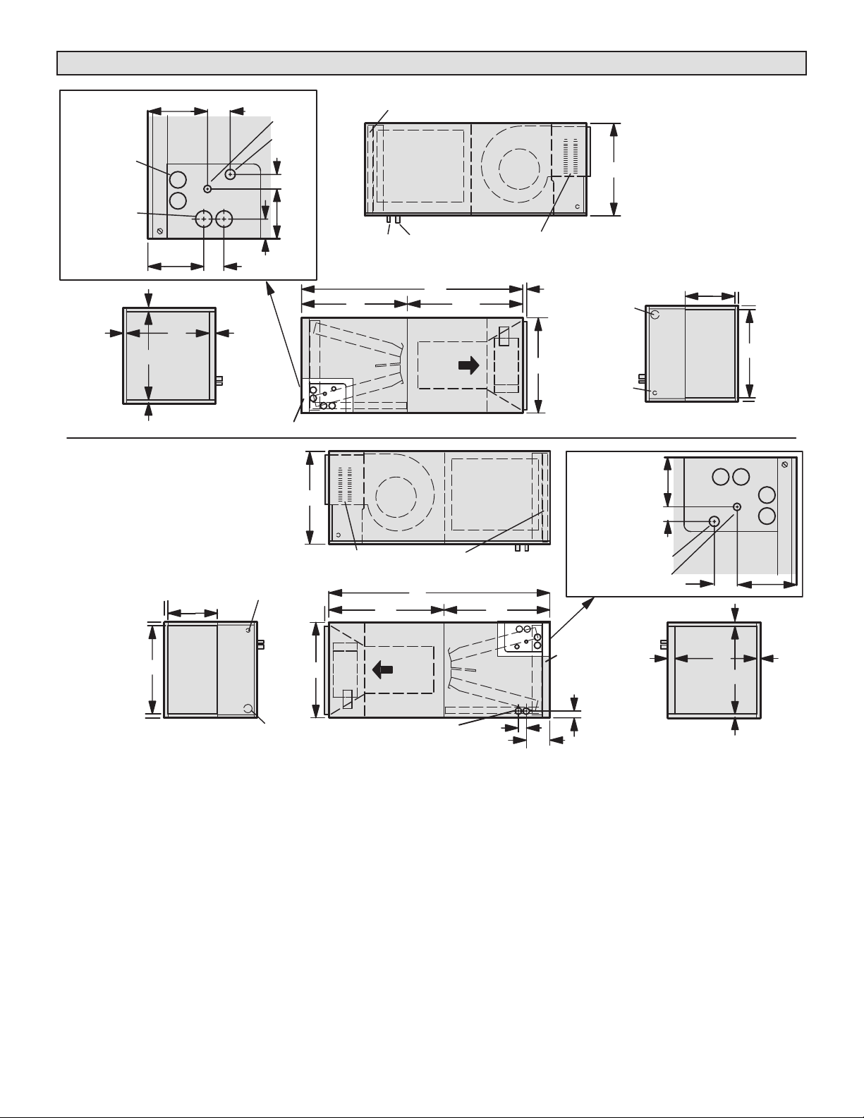
CBA38MV Horizontal Left- and Right-Hand Discharge Unit Dimensions – Inches (mm)
5‐3/8
(137)
CONDENSATE
DRAINS (2)
(UP-FLOW
AND
DOWN-FLOW)
CONDENSATE
DRAINS (2)
(HORIZONTAL)
PIPING PLAT E
DETAIL
5/8 (16)
5/8 (16)
5/8 (16)
5‐3/4
(46)
E
RETURN AIR
OPENING
F
END VIEW
Horizontal Position
(Left‐Hand Air
Discharge)
1‐3/4
(44)
(51)
2
1‐1/2
(38)
1 (25)
FILTER ACCESS
LIQUID
LINE
SUCTION
LINE
1‐1/8
(29)
4‐3/8
(111)
FILTER
Horizontal Position
(Right‐Hand Air
Discharge)
Coil
LIQUID
SUCTION
LINE
LINE
TOP VIEW
A
H
AIR
FLOW
FRONT VIEW
C
BLOWER
BLOWER
OPTIONAL ELECTRIC
HEAT (FIELD-INSTA LLED)
G
Coil
5/8 (16)
B
INLETS (BOTTOM
C
LINE VOLTAGE
INLETS (TOP
AND RIGHT
SIDE)
LOW VOLTAGE
AND RIGHT
SIDE)
FOR DIMENSIONS “A” THROUGH
“H”, SEE CHART ON PAGE 2.
11‐1/16
3/4 (19)
(281)
Supply
4‐3/8
(111)
1‐1/8
(29)
Air
Opening
END VIEW
D
3/4 (19)
3/4 (19)
3/4 (19)
3/4 (19)
LOW VOLTAGE
3/4 (19)
11‐1/16
(281)
Supply
D
Air Opening
LINE VOLTAGE INLETS
(BOTTOM AND LEFT SIDE)
END VIEW
INLETS (TOP AND
LEFT SIDE)
OPTIONAL ELECTRIC
HEAT (FIELD INSTALLED)
5/8 (16)
B
CONDENSATE DRAINS (2)
A
G
Air Flow
(HORIZONTA L)
FRONT VIEW
FILTER
TOP VIEW
SUCTION
LINE
H
1‐3/4
(44)
LIQUID
LINE
5‐3/4
(146)
SUCTION LINE
PIPING PLAT E
DETAIL
FILTER ACCESS
1‐1/2 (38)
LIQUID
LINE
1 (25)
E
Return
Air Opening
END VIEW
(51)
2
5‐3/8
(137)
5/8 (16)
5/8 (16)
F
5/8 (16)
Page 3
Page 4
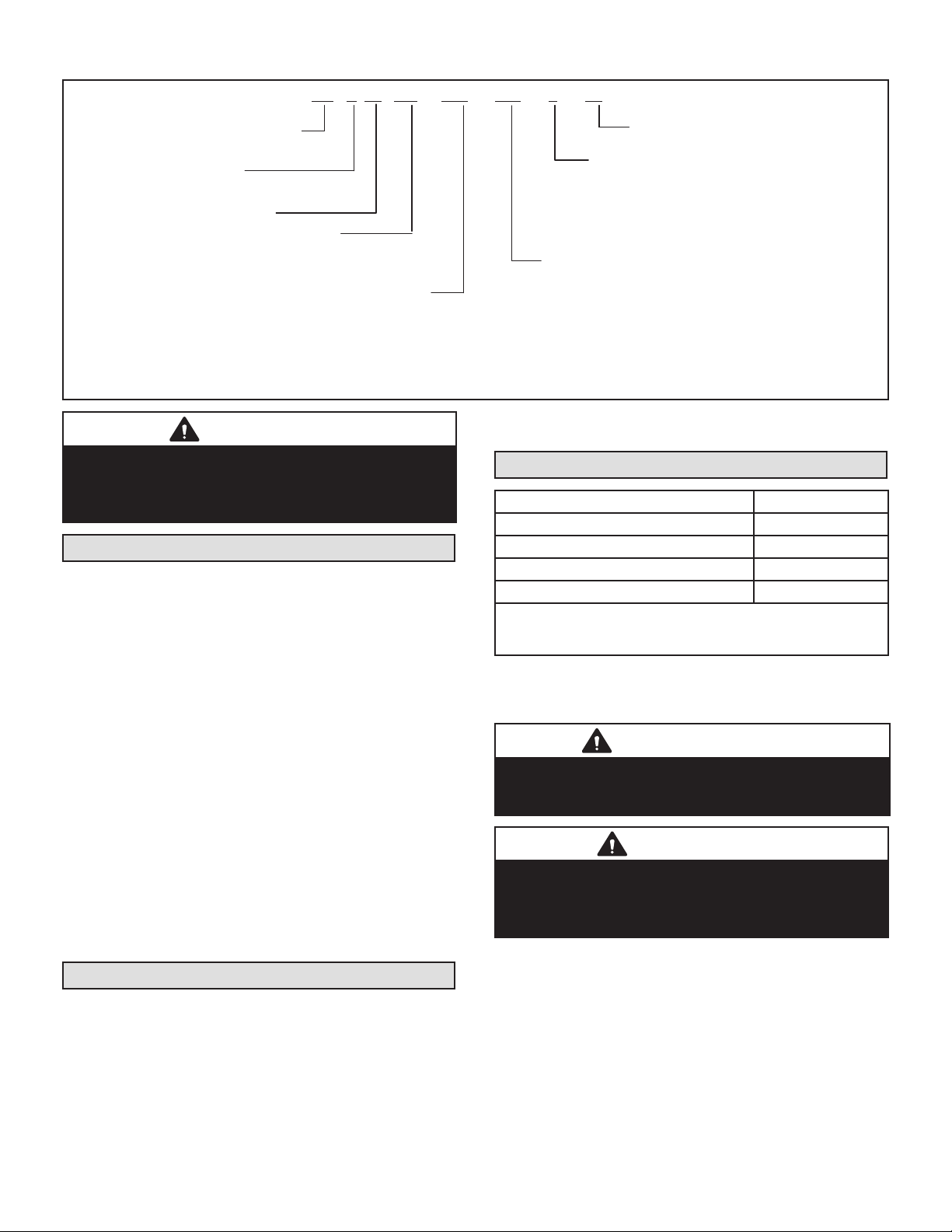
Model Number Identication
230CB 38 036-01
060 = 5 tons (17.6 kW)
-
--6
MV
A
Unit Type
CB = Air Handler
Coil Type
A = Aluminum Coil
Series
Configuration
MV = Multi-Position, Variable
speed blower motor
Nominal Cooling Capacity
018/024 = 1.5 to 2 tons (5.3 to 7 kW)
030 = 2.5 tons (8.8 kW)
036 = 3 tons (10.6 kW)
042 = 3.5 tons (12.3 kW)
048 = 4 tons (14.1 kW)
CAUTION
As with any mechanical equipment, contact with sharp
sheet metal edges can result in personal injury. Take
care while handling this equipment and wear gloves and
protective clothing.
General Information
This indoor unit with all-aluminum coil is designed for
installation with optional eld-installed electric heat and a
matched outdoor unit that is charged with HFC-410A refrigerant. These units, designed for indoor installation in
multiple positions, are completely assembled for upow
and horizontal right-hand discharge before being shipped
from the factory.
All CBA38MV air handlers are equipped with a factory-installed, internally mounted check / expansion valve, which
is suitable for use in HFC-410A applications.
This air handler is compatible with the ComfortSense®
non-communicating thermostat and non-communicating
outdoor units. In addition, this unit has the enhanced capability of communicating with the communicating thermostats and communicating outdoor units using the Lennox
RSBus protocols.
NOTE - For downow or horizontal left-hand air discharge,
certain eld modications are required.
These instructions are intended as a general guide and do
not supersede local or national codes in any way. Consult
authorities having jurisdiction before installation.
Minor Revision Number
Refrigerant Metering Device
2 = Fixed Orifice
3 = TXV - Bleed port (indoor unit)
4 = TXV - Non-bleed port (indoor unit)
5 = TXV - Non-bleed port (outdoor unit)
6 = TXV - R410A Non-bleed port (indoor
unit)
Voltage
230 = 208/230V-60hz-1ph
Check the air handler for shipping damage; if found, immediately contact the last carrier.
Installation Clearances
Cabinet 0 inch (0 mm)
To Plenum 0 inch (0 mm)
To Outlet Duct within 3 feet (914 mm) 0 inch (0 mm)
Floor See Note #1
Service / Maintenance See Note #2
1
Units installed on combustible oors in the downow position with
electric heat require optional downow additive base.
2
Front service access – 24 inches (610 mm) minimum.
NOTE - If cabinet depth is more than 24 inches (610 mm),
allow a minimum of the cabinet depth plus 2 inches (51
mm).
IMPORTANT
This unit must be matched with an indoor coil as
specied in the Lennox Product Specications (EHB).
Coils previously charged with HCFC-22 must be ushed.
WARNING
During blower operation, the ECM motor emits
energy that may interfere with pacemaker operation.
Interference is reduced by both the sheet metal cabinet
and distance.
Shipping and Packing List
Package 1 of 1 contains:
1 – Assembled air handler unit
1 – Pipe nipple (Sch80, 3/4" I.D. x 5")
1 – Downow shields and foam tapes (required for down-
ow conguration only)
1 – Horizontal drip shield (CBA38MV-060 only)
1 – Warranty card
Page 4
Page 5
WARNING
Improper installation of the air handler can result in
personal injury or death.
Do not allow external combustion products or other
contaminants to enter the return air system or to be
mixed with air that will be supplied to the living space.
Use sheet metal screws and joint tape or duct mastic to
seal return air system to air handler. In platform
installations, the air handler should be sealed airtight to
the return air plenum. A door must never be used as
a portion of the return air duct system. The base must
provide a stable support and an airtight seal to the air
handler. Allow absolutely no sagging, cracks, gaps. etc.
For no reason should return and supply air duct systems
ever be connected to or from other heating devices
such as a replace or stove. etc. Fire, explosion, carbon
monoxide poisoning, personal injury and/or property
damage could result.
Requirements
In addition to conforming to manufacturer’s installation instructions and local municipal building codes, installation
of Lennox air handler units (with or without optional electric heat), shall conform with the following National Fire
Protection Association (NFPA) standards:
• NFPA No. 90A - Standard for Installation of Air Conditioning and Ventilation Systems
• NFPA No. 90B - Standard for Installation of Residence
Type Warm Air Heating and Air Conditioning Systems
This unit is approved for installation clearance to combustible material as stated on the unit rating plate. Accessibility and service clearances must take precedence over
combustible material clearances.
4 - Replace access panel.
UPFLOW APPLICATION
Use the following procedures to congure the unit for upow operations:
1 - Remove access panels.
2 - Remove and discard the horizontal drip shield (-060
model, used only on horizontal applications) and
the corrugated padding between the blower and coil
assembly.
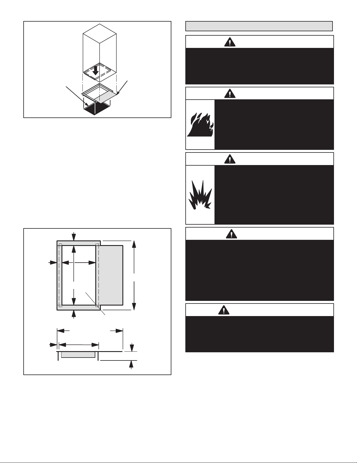
3 - The horizontal drain pan must be removed when
the coil blower is installed in the upow position.
Removing the horizontal drain pain will allow proper
air ow and increased eciency.
4 - After removing the horizontal drain pan, place the
unit in the desired location. Set unit so that it is level.
Connect return and supply air plenums as required
using sheet metal screws as illustrated in gure 1.
5 - Install units that have no return air plenum on a
stand that is at least 14" from the oor to allow for
proper air return. Lennox oers an optional upow
unit stand as listed in table 1.
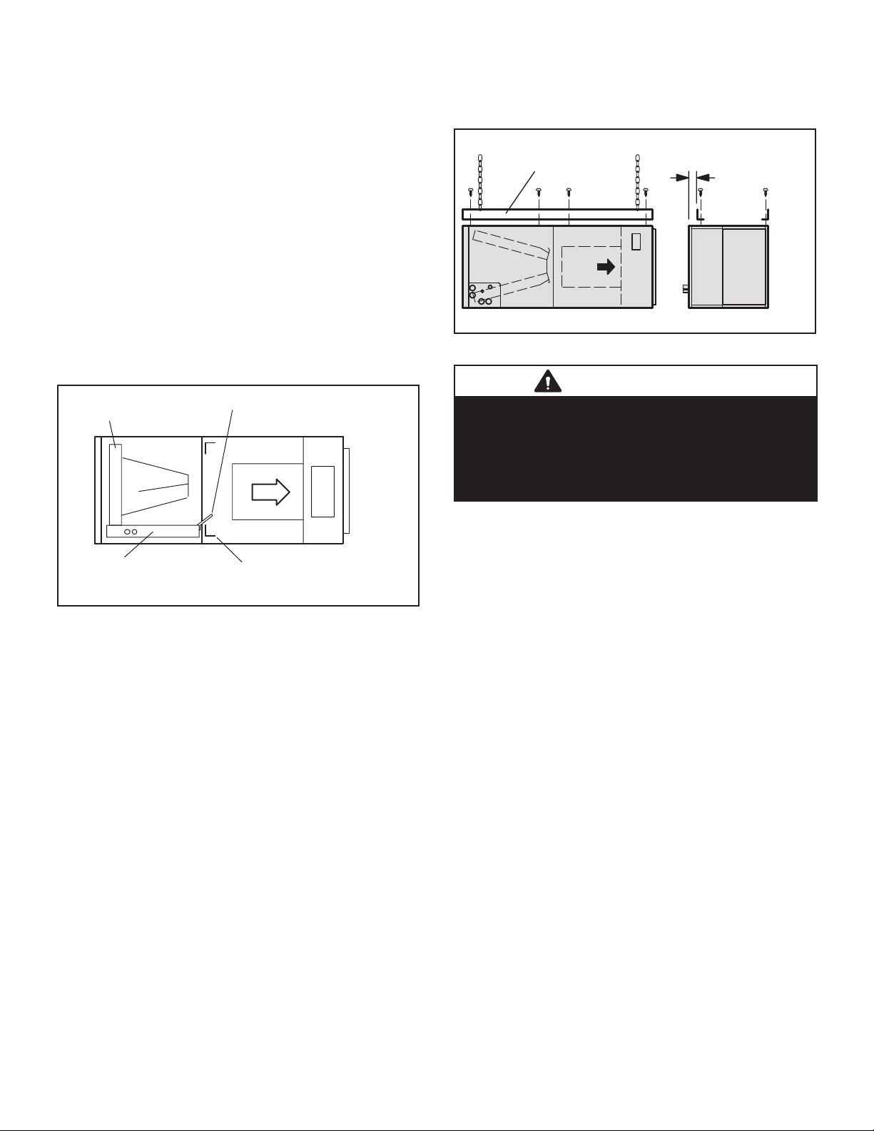
HORIZONTAL DRAIN PAN
(MUST BE REMOVED)
UP-FLOW /
DOWN-FLOW
DRAIN PAN
Installing the Unit
These units are factory-congured for upow and horizontal right-hand discharge installation. For downow or
horizontal left-hand discharge, certain eld modications
are required.
DISASSEMBLE/REASSEMBLE AIR HANDLER UNITS
The air handler units consists of two factory-assembled
sections. It may be necessary to disassemble the sections
when positioning the unit for installation.
To disassemble:
1 - Remove access panels.
2 - Remove both blower and coil assemblies. This will
lighten the cabinet for lifting.
3 - Remove one screw from the left and right posts
inside the unit. Remove one screw from each side on
the back of the unit. Unit sections will now separate.
To reassemble:
1 - Align cabinet sections together.
2 - Reinstall screws.
3 - Replace blower and coil assemblies.
FIGURE 1. Upow Conguration
TABLE 1. Optional Side-Return Unit Stand
(Upow Only)
Model Kit Number
All unit sizes
45K32
HORIZONTAL RIGHT-HAND DISCHARGE
APPLICATION
Use the following procedures to congure the unit for horizontal right-hand discharge operations:
NOTE – For horizontal applications, a secondary drain
pan is recommended. Refer to local codes.
NOTE – When air handler is located above a nished
space, the secondary drain pan must have a larger footprint than the air handler. In addition, a 3/4" (19.1mm)
overow drain line must be:
• Connected to secondary drain pan
or
• Connected to the overow drain outlet of the air handler
drain pan.
Page 5
Page 6
NOTE - (-060 Model Only) Before operating the unit, re-
UP-FLOW / DOWN-FLOW
DRAIN
HORIZONT
PA
FRONT VIEW END VIEW
move access panels and the horizontal drip shield and the
corrugated padding between the blower and coil assembly. Discard the corrugated padding and the downow drip
shields.
NOTE - (-060 Model Only) Install the horizontal shield on
the front edge of the horizontal drain pan as illustrated in
gure 2.
1 - No further adjustment is necessary. Set unit so that it
is sloped 1/4" towards the drain pan end of the unit.
2 - If the unit is suspended, the entire length of the
cabinet must be supported. If you use a chain or
strap, use a piece of angle iron or sheet metal
attached to the unit (either above or below) to
support the length of the cabinet. Use securing
screws no longer than 1/2" to avoid damaging the
coil or lter as illustrated in gure 3. Use sheet
metal screws to connect the return and supply air
plenums as required.
HORIZONTAL DRIP SHIELD (-060 MODELS)
PAN
2 - Remove the downow rail then replace screws.
3 - Seal around the exiting drain pipe, liquid line, and
suction line to prevent humid air from inltrating into
the unit.
1/2" SCREWS MAXIMUM
ANGLE IRON OR
SHEET METAL
ELECTRICAL INLET CLEARANCE 4"
(102 mm)
FIGURE 3. Suspending Horizontal Unit
IMPORTANT
When removing the coil, there is possible danger of
equipment damage and personal injury. Be careful when
removing the coil assembly from a unit installed in rightor left-hand applications. The coil may tip into the drain
pan once it is clear of the cabinet. Support the coil when
removing it.
N
FIGURE 2. Right-Hand Discharge Conguration
HORIZONTAL RIGHT-HAND DISCHARGE
APPLICATION IN HIGH-HUMIDITY AREAS
For horizontal applications in high humidity areas, remove
the downow rail closest to the drain pan.
To remove rail:
1 - Remove the screws from the rail at the back of unit
and at the cabinet support rail.
AL DRAIN
NO ADJUSTMENT IS NECESSARY
DOWN-FLOW RAIL
HORIZONTAL LEFT-HAND DISCHARGE
APPLICATION
NOTE – For horizontal applications, a secondary drain
pan is recommended. Refer to local codes.
NOTE - (-060 Model Only) Before operating the unit, re-
move access panels and the horizontal drip shield and the
corrugated padding between the blower and coil assembly. Discard the corrugated padding and the downow drip
shields. (The shields are used for downow applications
only.)
Page 6
Page 7
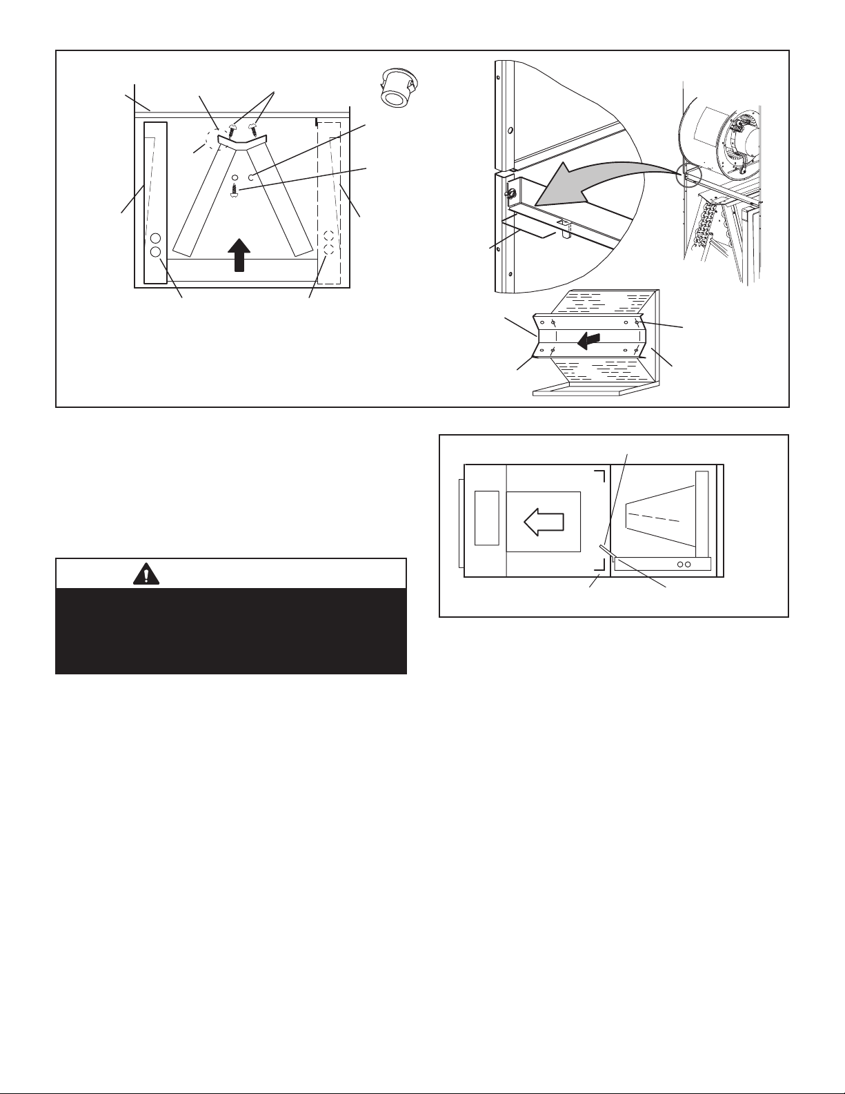
HORIZONTAL DRIP SHIELD (-060 MODEL)
DRAIN PAN
CABINET
SUPPORT
DRAIN PAN
REINSTALLED
HERE
TOP CAP ROTATED TO
CORRECT POSITION
90º
BEND
TOP CAP
SCREWS
3/16” PLASTIC
PLUG (REAR COIL
END SEAL)
HORIZONTA L DRIP
SHIELD SCREW
(FRONT COIL END
SEAL)
DRAIN PAN
SHIPPING
LOCATION
INSTALL DRAIN PAN
BETWEEN TA B AND
EXTERIOR INNER WALL.
DETAIL C
REINSTALLED HERE REMOVED FROM HERE
———— DRAIN PLUGS ————
FRONT VIEW
COIL SHOWN IN UPFLOW POSITION FOR EASY
CONVERSION (LEFT-HAND AIR DISCHARGE )
DETAIL A
FIGURE 4. Field Modication for Left-Hand Discharge
Use the following procedures to congure the unit for horizontal left-hand discharge operations:
1 - Pull the coil assembly from unit. Pull o the horizontal
drain pan.
2 - Remove the drain plugs from back drain holes on
horizontal drain pan and reinstall them on front
holes.
IMPORTANT
After removal of drain pan plug(s), check drain hole(s)
to verify that drain opening is fully open and free of any
debris. Also check to make sure that no debris has fallen
into the drain pan during installation that may plug up the
drain opening.
3 - Rotate drain pan 180º front-to-back and install it on
the opposite side of the coil.
4 - Remove screws from top cap. Remove horizontal
drip shield screw located in the center of the back
coil end seal as illustrated in gure 4 on page 5.
5 - Rotate horizontal drip shield 180º front-to-back.
6 - Remove plastic plug from left hole on coil front
end seal and reinstall plug in back hole. Reinstall
horizontal drip shield screw in front coil end seal.
Drip shield should drain downward into horizontal
drain pan inside coil.
NOTE – Be very careful when reinstalling the screws into
the coil end plate engaging holes. Misaligned screws may
damage the coil.
7 - From the upow position, ip cabinet 90º to the
left and set into place. Replace blower assembly.
Secure coil in place by bending down the tab on the
cabinet support rail as illustrated in gures 4 and 5.
TOP CAP
DETAIL B
BEND
90º
DOWN-FLOW RAIL FRONT EDGE OF HORIZONTAL
ALIGN HOLES WITH
HOLES IN COIL END
PLATE. STARTING WITH
THE ROUND HOLES ON
THIS END.
BACK COIL
END SEAL
FIGURE 5. Left-Hand Discharge Conguration
8 - Install the horizontal shield (-060 model) on the
front edge of the horizontal drain pan as illustrated
in gure 5.
NOTE – For horizontal applications in high humidity ar-
eas, remove the downow rail closest to the drain pan. To
remove rail, remove screw from rail at back of unit and at
cabinet support rail. Remove downow rail then replace
screws. Also, seal around the exiting drain pipe, liquid and
suction lines to prevent inltration of humid air.
9 - Knock out drain seal plate from access door. Secure
plate to cabinet front ange with screw provided.
10 - Flip access door and replace it on the unit.
11 - Set unit so that it is sloped 1/4ʺ toward the drain
pan end of the unit. Connect return and supply air
plenums as required using sheet metal screws.
Page 7
Page 8
AN
DOWNFLO
1” WIDE FOAM TAPE (LONGER PIECE)
12 - If suspending the unit, it must be supported along the
entire length of the cabinet. If using chain or strap,
use a piece of angle iron or sheet metal attached
to the unit (either above or below) so that the full
length of the cabinet is supported. Use securing
screws no longer than 1/2ʺ to avoid damage to coil
or lter, as illustrated in gure 3 on page 6. Connect
return and supply air plenums as required using
sheet metal screws.
DOWNFLOW APPLICATION
Use the following procedures to congure the unit for
downow operations:
IMPORTANT
If electric heat section with circuit breakers (ECB29/
ECB31) is installed in a CBA38MV unit in a downow
application, the circuit breakers must be rotated 180°
to the UP position. See ECB29/ECB31 installation
instructions for more details.
HORIZONTA L DRAIN P
(REMOVE FROM UNIT)
UP-LOAD /
W
DRAIN PAN
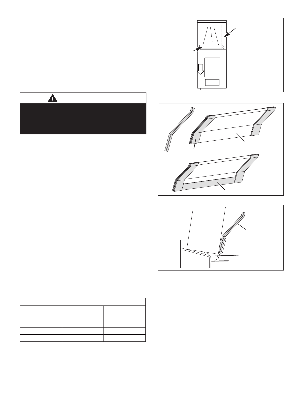
FIGURE 6. Downow Discharge Position
Table 2 outlines the sizes of the various drip shields.
NOTE - (-060 Model Only) Remove access panels and
horizontal drip shield from the corrugated padding between the blower and coil assembly.
1 - Remove the coil assembly from the unit.
2 - For best eciency and air ow, remove the
horizontal drain pan from the units in downow
positions as illustrated in gure 6.
3 - Rotate cabinet 180º from the upright position. See
gure 6. You may need to rst remove the blower
assembly to lighten the cabinet for lifting.
4 - Foam tape that is provided creates a seal between
the drip shield and the coil so that water does not
leak into the air stream. The foam tape pieces
are precut. Apply the tape to the drip shields as
illustrated in gure 7 and specied as follows:
• Apply two pieces of foam tape provided down both
ends of each shield. The tape should measure
4-3/4ʺ X 2ʺ (120 X 25 mm). Ensure that the tape
covers both sides of the shield equally.
• Apply the longer piece of 1 inch wide foam tape between the end pieces of tape.
5 - From the underside of the coil, install the downow
drip shield rmly in place as illustrated in gure 8.
TABLE 2. Downow Drip Shields (Tape Required)
Units Length Width
-018/024 Not Required Not Required
-030 15-7/8ʺ 4-11/16ʺ
-036, -042 17-7/8ʺ 4-11/16ʺ
-048, -060 19-7/8ʺ 4-11/16ʺ
DRIP SHIELD
SIDE
VIEW
2” WIDE FOAM TAPE
FIGURE 7. Applying Foam Tape to Drip Shield
COIL
DRIP SHIELD
DRIP PAN
FIGURE 8. Downow Drip Shields
6 - Replace the coil assembly and blower if you have
removed it. Replace the coil access panel.
7 - Set the unit so that it is level. Using sheet metal
screws, connect the return and supply air plenums
as required.
NOTE - For downow application, metal or Class I supply
and return air plenums must be used.
Page 8
Page 9
AIR
HANDER
UNIT
COMBUSTIBLE FLOOR
PROPERLY SIZED
FLOOR OPENING
ADDITIVE BASE
FIGURE 9. Downow Combustible Flooring Base
8 - For downow installation on combustible ooring,
an additive base must be used as illustrated in gure
9 on page 9. See CBA38MV Product Specications
(EHB) for downow combustible ooring base kits
available for this air handler.
9 - Cut an opening appropriately sized for combustible
base. Base dimensions are illustrated in gure 10.
After opening has been cut, set the additive base
into opening. Connect outlet air plenum to the
additive base. Set the unit on the additive base so
anges of the unit drop into the base opening and
seal against the insulation strips. The unit is now
locked in place. Install return air plenum and secure
with sheet metal screws.
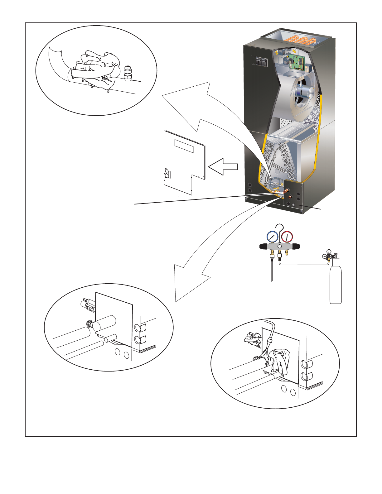
Brazing Connections
WARNING
Polyol ester (POE) oils used with HFC-410A refrigerant
absorb moisture very quickly. It is very important that the
refrigerant system be kept closed as much as possible.
DO NOT remove line set caps or service valve stub caps
until you are ready to make connections.
WARNING
Danger of re. Bleeding the refrigerant
charge from only the high side may result
in pressurization of the low side shell and
suction tubing. Application of a brazing torch
to a pressurized system may result in ignition
of the refrigerant and oil mixture. Check the
high and low pressures before applying heat.
WARNING
Danger of explosion!
Can cause equipment damage, injury, or
death.
When using a high pressure gas such as
nitrogen to pressurize a refrigeration or air
conditioning system, use a regulator that can
control the pressure down to 1 or 2 psig (6.9
to 13.8 kPa).
1‐5/8 (41)
1‐5/8 (41)
20 (508)
1‐5/8 (41)
5/8 (16)
TOP VIEW
11‐3/8
(289)
SUPPLY AIR OPENING
22‐5/8 (575) -018/024
24‐5/8 (625) -030, 036
26‐5/8 (676) -042, 048, 060
13‐1/2 (343)
OPENING
SIDE VIEW
23-1/4 (591)
INCHES (MM)
3 (76)
FIGURE 10. Downow Combustible Base Dimensions
CAUTION
Brazing alloys and ux contain materials which are
hazardous to your health.
Avoid breathing vapors or fumes from brazing operations.
Perform operations only in well ventilated areas.
Wear gloves and protective goggles or face shield to
protect against burns.
Wash hands with soap and water after handling brazing
alloys and ux.
IMPORTANT
To prevent the build-up of high levels of nitrogen when
purging, it must be done in a well-ventilated area. Purge
low-pressure nitrogen (1 to 2 psig) through the refrigerant
piping during brazing. This will help to prevent oxidation
and the introduction of moisture into the system.
Page 9
Page 10
LINE.
PLEASE READ IMPORTANT ISSUES CONCERNING BRAZING
NOTE — REFER TO OUTDOOR UNIT INSTALLATION INSTRUCTIONS
FOR REFRIGERANT PIPING SIZE REQUIREMENTS .
NOTE - Use silver alloy brazing rods with five or six percent
minimum silver alloy for copper-to-copper brazing, 45
percent alloy for copper-to-brass and copper-to-steel
brazing.
REMOVE ACCESS PANEL
A
REMOVE RUBBER PLUG FROM BOTH LIQUID
B
AND SUCTION LINES
NOTE — CBA38MV SERIES UNITS USE NITROGEN OR DRY AIR
AS A HOLDING CHARGE. IF THERE IS NO PRESSURE WHEN
THE RUBBER PLUGS ARE REMOVED, CHECK THE COIL FOR
LEAKS BEFORE INSTALLING.
EITHER REMOVE OR PUSH PIPE WRAPPING BACK
D
THROUGH HOLE IN PIPING PLATE BEFORE LINE
SET CONNECTION AND BRAZING.
OPERATIONS ON PAGE 10 BEFORE PROCEEDING.
USE A WET RAG TO PROTECT CTXV
C
SENSING BULB WHEN BRAZING
SUCTION LINE CONNECTIONS.
LOW
HIGH
PIPING
PLATE
CONNECT PIPES
E
NOTE — REFRIGERANT LINE SETS
SHOULD BE ROUTED TO ALLOW
FILTER ACCESSIBILITY.
REPEAT PREVIOUS PROCEDURE FOR LIQUID
I
FLOW REGULATED NITROGEN (AT 1 TO 2 PSIG)
THROUGH THE REFRIGERATION GAUGE SET INTO THE
VALV E STEM PORT CONNECTION ON THE OUTDOOR
UNIT LIQUID LINE SER VICE VALVE AND OUT OF THE
VALV E STEM PORT CONNECTION ON THE SUCTION
SERVICE VALVE.
PLACE A WET RAG AGAINST PIPING
G
PLATE AND AROUND THE SUCTION
LINE CONNECTION. A
BRAZE CONNECTION. ALLOW PIPE TO
H
COOL BEFORE REMOVING WET RAG
FROM CTXV SENSING BULB AND PIPING
PANEL AREA.
FIGURE 11. Brazing Connections
CONNECT GAUGES AND
F
START NITROGEN FLOW
REFER TO INSTRUCTIONS PROVIDED WITH OUTDOOR UNIT FOR
LEAK TESTING, EVACUATING AND CHARGING PROCEDURES
NITROGEN
Page 10
Page 11
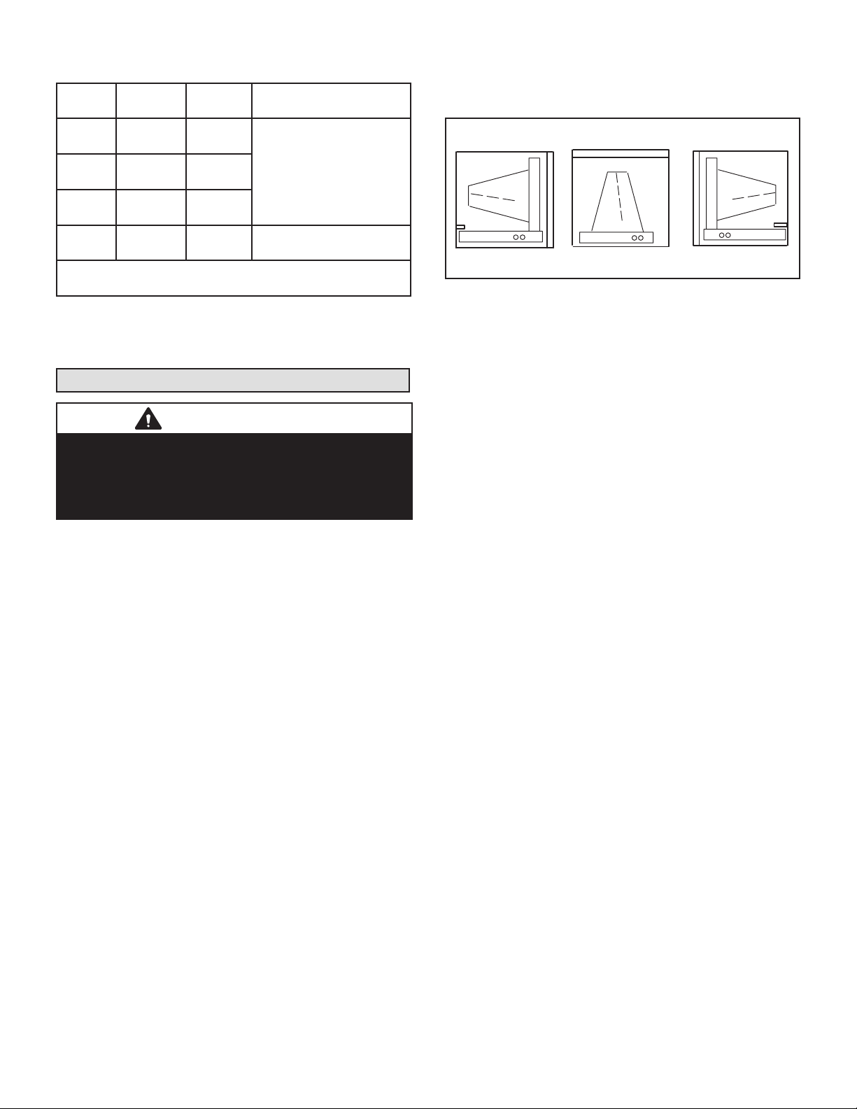
TABLE 3. CBA38MV Refrigerant Connections and
LEFT-HAND AIR
UP-FLOW OR
RIGHT-HAND AIR
Line Set Requirements
Model
-018/
024
-030
-036
-042
-048
-060
NOTE - Some applications may require a eld-provided 7/8ʺ
to 1-1/8ʺ adapter.
Liquid
Line
3/8ʺ
(10mm)
3/8ʺ
(10mm)
3/8ʺ
(10mm)
3/8ʺ
(10mm)
Vapor
Line
3/4ʺ
(19mm)
3/4ʺ
(19mm)
7/8"
(22mm)
7/8"
(22mm)
L15 Line Sets
L15 line set sizes are
dependant on unit
match-up. See Product
Specications (EHB) for
outdoor unit to determine
correct line set sizes
Field fabricated
NOTE - When installing refrigerant lines longer than 50
feet, see the Lennox Refrigerant Piping Design and Fabrication Guidelines, CORP. 9351-L9, or contact Lennox
Technical Support Product Applications for assistance.
Installing the Condensate Drain
IMPORTANT
After removal of drain pan plug(s), check drain hole(s)
to verify that drain opening is fully open and free of any
debris. Also check to make sure that no debris has fallen
into the drain pan during installation that may plug up the
drain opening.
MAIN DRAIN
Connect the main drain and route downward to drain line
or sump. Do not connect drain to a closed waste system.
See Figure 13 for typical drain trap conguration.
OVERFLOW DRAIN
It is recommended that the overow drain is connected to
an overow drain line for all units. If overow drain is not
connected, it must be plugged with provided cap.
For downow orientation, the overow drain MUST be
connected and routed to a overow drain line. See Figure 12 for main and overow drain locations based on coil
orientation.
DISCHARGE
OVERFLOW
DRAIN ON LEFT
DOWN-FLOW
DISCHARGE
MAIN DRAIN ON
RIGHT
FIGURE 12. Main and Overow Drain Locations
Based on Coil Orientation
BEST PRACTICES
The following best practices are recommended for the
condensate removal process:
• Main and overow drain lines should NOT be smaller
than both drain connections at drain pan.
• Overow drain line should run to an area where home-
owner will notice drainage.
• It is recommended that the overow drain line be vented
and a trap installed. Refer to local codes.
• Condensate drain lines must be congured or provided
with a cleanout to permit the clearing of blockages and
for maintenance without requiring the drain line to be
cut.
Page 11
Page 12
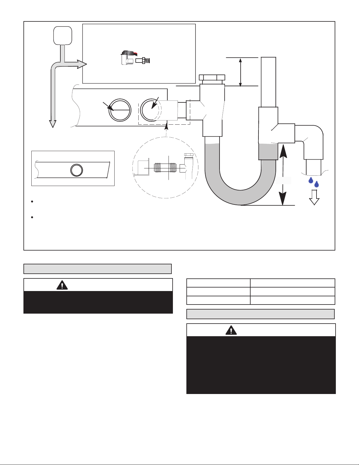
ABOVE
PIPE NIPPLE PROVIDED IN BAG ASSEMBLY - SCH 80, 3/4” I. D. X 5” - 34K7401 (1): CUT THE PIPE IN HALF AND USE IT TO ROUTE THE MA IN DRAIN.
FINISHED
SPACE?
OVERFLOW DRAIN LINE
ALWAYS RUN AN OVERFLOW DRAIN LINE. IF NOT POSSIBLE TO
ROUTE OVERFLOW DRAIN LINE, INSTA LL LOW VOLTAGE
OVERFLOW SWITCH KIT. WIRE KIT TO SHUT DOWN
COMPRESSOR PER INSTRUCTIONS.
LENNOX #
X3169
COMPACT OVERFLOW SWITCH WITH 3/4” FEMALE SLIP INLET
NO
AND MALE ADAPTER, TWO PA RT DESIGN FOR USE WHERE
OBSTRUCTIONS PREVENT DIRECT THREADING
CLEAN OUT
PRESS IN
(DO NOT GLUE)
VENT MUST EXTEND
ABOVE HEIGHT OF
COIL DRAIN PAN BY
TWO INCHES (51MM)
VENT
MAIN
MAIN
DRAIN
PIPE NIPPLE
AIR HANDLER DRAIN PA N
OVERFLOW
DRAIN
YES
NOTE — WHEN A AIR HANDLER IS LOCATED
ABOVE A FINISHED SPACE THE SECONDARY
DRAIN PA N MUST HAVE A LARGER FOOTPRINT
THAN THE AIR HANDLER.
DRAIN
SECONDARY
DRAIN PAN
WHEN A COIL IS LOCATED ABOVE A FINISHED SPACE, A
3/4” (19.1MM) SECONDARY DRAIN LINE MUST BE:
CONNECTED TO SECONDARY DRAIN PAN
OR
CONNECTED TO THE OVERFLOW DRAIN OUTLET OF
THE AIR HANDLER DRAIN PAN.
TRAPS MUST BE DEEP ENOUGH TO OFFSET MAXIMUM STATIC DIFFERENCES —
GENERALLY, TWO INCHES (51MM).
1
LENNOX P-TRAP 49P66 REQUIRES A LARGER INSTALLATION SPACE THAN THE J-TRAP 91P90.
2
FIGURE 13. Typical Main and Overow Drain Installations
CUT TO
REQUIRED
LENGTH
PROVIDED
SIDE VIEW
1” X 3/4” X 3/4”
REDUCING
TEE WITH
PLUG
1
P-TRAP
LENNOX
49P66, J-TRAP #
91P90 OR ANY
PVC SCH 40 P- OR
J-TRAP 3/4”
2
FOR NEGATIVE PRESSURE COILS (BLOWER
AFTER COIL) TRAPS ARE REQUIRED ON ALL
DRAIN LINES CONNECTED TO COIL.
2”
(51MM)
TRAP DEPTH
TO APPROVED
DRAIN
DRAIN LINE SHOULD
SLOPE A MINIMUM OF
ONE INCH PER 10
FEET (25MM PER 3
METERS)
Inspecting and Replacing Filters
IMPORTANT
Filter access door must be in place during unit operation.
Excessive warm air entering the unit from unconditioned
space may result in water blow-o problems.
Filters may be duct-mounted or installed in the cabinet. A
lter is installed at the factory. Note that lter access door
ts over access panel. Air will leak if the access panel is
placed over the lter door.
Filters should be inspected monthly and must be cleaned
or replaced when dirty to assure proper furnace operation.
To replace lter:
1 - Loosen the thumbscrews holding the lter panel in
place.
2 - Slide the lter out of the guides on either side of
cabinet.
3 - Insert new lter.
4 - Replace panel.
See table 4 for replacement lter sizes.
TABLE 4. Filter Dimensions
CBA38MV Filter Size – In. (mm)
-018/024, -030, -036 20 x 20 x 1 (508 x 508 x 25)
-042, -048, -060 20 x 24 x 1 (508 x 610 x 25)
Sealing the Unit
WARNING
There must be an airtight seal between the bottom of
the air handler and the return air plenum. Use berglass
sealing strips, caulking, or equivalent sealing method
between the plenum and the air handler cabinet to
ensure a tight seal. Return air must not be drawn from a
room where this air handler or any gas-fueled appliance
(i.e., water heater), or carbon monoxide-producing
device (i.e., wood replace) is installed.
Seal the unit so that warm air is not allowed into the cabinet. Warm air introduces moisture, which results in water
blow-o problems. This is especially important when the
unit is installed in an unconditioned area.
Page 12
Page 13
Make sure the liquid line and suction line entry points are
sealed with either the provided exible elastomeric thermal insulation, or eld provided material (e.g. Armaex,
Permagum or equivalent). Any of the previously mentioned materials may be used to seal around the main and
auxiliary drains, and around open areas of electrical inlets.
Field Control Wiring
WARNING
Electric Shock Hazard.
Can cause injury or death.
Foil-faced insulation has conductive characteristics
similar to metal. Be sure there are no electrical
connections within a ½ʺ of the insulation. If the foil-faced
insulation comes in contact with electrical voltage, the
foil could provide a path for current to pass through to
the outer metal cabinet. While the current produced
may not be enough to trip existing electrical safety
devices (e.g. fuses or circuit breakers), the current can
be enough to cause an electric shock hazard that could
cause personal injury or death.
Wiring must conform to the current National Electric Code
ANSI/NFPA No. 70, or Canadian Electric Code Part I, CSA
Standard C22.1, and local building codes. Refer to following wiring diagrams. See unit nameplate for minimum circuit ampacity and maximum over-current protection size.
WARNING
Run 24V Class II wiring only through specied low
voltage opening. Run line voltage wiring only through
specied high voltage opening. Do not combine voltage
in one opening
Select the proper supply circuit conductors in accordance
with tables 310-16 and 310-17 in the National Electric
Code, ANSI/NFPA No. 70 or tables 1 through 4 in the Canadian Electric Code, Part I, CSA Standard C22.1.
Separate openings have been provided for 24V low voltage and line voltage. Refer to the dimension illustration of
specic location.
CAUTION
USE COPPER CONDUCTORS ONLY.
WIRING CONNECTIONS
1 - Install line voltage power supply to unit from a
properly installed circuit breaker.
2 - Ground unit at unit disconnect switch or to an earth
ground.
NOTE – Connect conduit to the unit using a proper conduit tting. Units are approved for use only with copper
conductors. A complete unit wiring diagram is located on
the back side of the unit’s access panel.
3 - Install low voltage wiring from outdoor to indoor unit
and from thermostat to indoor unit.
NOTE – For proper voltages, select thermostat wire gauge
per the following chart:
ELECTROSTATIC
DISCHARGE
(ESD)
Precautions and
Procedures
CAUTION
Electrostatic discharge can aect
electronic components. Take care
during unit installation and service to
protect the unit’s electronic controls.
Precautions will help to avoid
control exposure to electrostatic
discharge by putting the unit, the
control and the technician at the
same electrostatic potential. Touch
hand and all tools on an unpainted
unit surface before performing any
service procedure to neutralize
electrostatic charge.
Page 13
Page 14
Cut Size: 7" wide x 10" tall
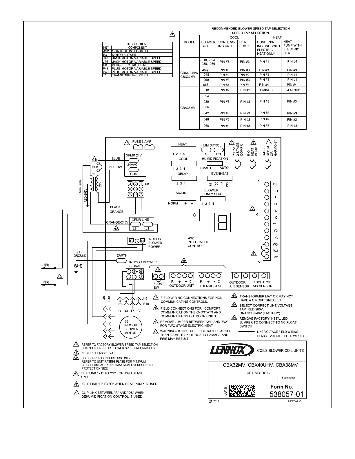
FIGURE 14. CBA38MV Air Handler Unit Typical Wiring Diagram
Page 14
Page 15

DETAIL A
NOTE - Due to varying duct designs
and air flow conditions, relocation of
the discharge sensor may be required
to insure accurate sensing.
ELECTRIC HEAT RELAY
PART NO. 49W91
19 IN.
(483 MM)
SENSOR
(CENTER SIDE-T0 -SIDE)
5-1/2 IN.
(140 MM)
THE AIR HANDLER CONTROL (AHC) HAS
TWO SCREW TERMINALS MARKED
DISCHARGE AIR SENSOR. THE SENSOR
IS REQUIRED FOR EVENHEAT
OPERATION, IS FIELD-MOUNTED AND
MUST BE ORDERED SEPARATELY
(CATALOG # 88K38).
DISCHARGE SENSOR
(DAT)
TEMPERATURE RESISTANCE
CHART
TEMPRESISTANCE
ºF (OHMS)
30 34,566
40 26,106
50 19,904
60 15,313
70 11,884
80 9,298
90 7,332
100 5,826
22V DIRECT CURRENT COIL
30 AMP CONTACT RATING
DETAIL B
9-PIN CONNECTOR
9-PIN
CONNECTOR
AIR
HANDLER
CONTROL
SECURING
SCREWS
AIR HANDLER CONTROL
L-BRACKET MOUNTING PLATE
CBA38MV AIR HANDLER CONTROL
PART NO. 16X40
FASTEN THE PROBE
BRACKET TO THE
PLENUM WITH TWO
SELF-TAPPING SHEET
METAL SCREWS.
PLENUM
NOTE — EVENHEAT MODE CANNOT BE ENABLED WITH
HARMONY III
DISCHARGE AIR SENSOR.
DUE TO EACH CONTROL REQUIRING ITS OWN
FIGURE 15. Component Connections
Page 15
CONNECT WIRES TO DISCHARGE AIR SENSOR
TERMINAL ON AIR HANDLER CONTROL.
Page 16

AIR
CONDITIONER
UNIT
(TWO-STAGE)
OPTIONAL
N.C. CONDENSATE
FLOAT SWITCH
RED
YELLOW
BLUE
BLACK
CBA38MV
R
W3
W2
W1
O
Y1
Y2
G
DS
C
COMFORTSENSE
7500
R
H
1
W2
W1
O
Y1
Y2
G
D
B
C
AIR HANDLER CONTROL COMES FROM FACTORY WITH A
METAL JUMPER BETWEEN W1 TO W2 AND W2 TO W3. SEE
1
FIGURE 21 FOR HEAT SECTION CONFIGURATION.
WHEN A CONVENTIONAL 24V NON-COMMUNICATING THERMOSTAT
IS USED WITH THE CBA38 AIR HANDLER, THE FLOAT SWITCH MUST
2
BE WIRED TO BREAK "Y1 COMPRESSOR DEMAND" WIRE TO THE
OUTDOOR UNIT. A FLOAT SWITCH CONNECTED TO "FLOAT SW"
TERMINALS WILL NOT SHUT OFF THE COOLING WHEN A 24V
NON-COMMUNICATING THERMOSTAT IS USED
DO NOT CONNECT A CONDENSATE FLOAT SWITCH TO THE "FLOAT SW"
3
TERMINAL WHEN A NON-COMMUNICATING THERMOSTAT IS USED
IMPORTANT – WHEN A CONVENTIONAL 24V NON-COMMUNICATING THERMOSTAT
IS USED WITH THE CBA38 AIR HANDLER, THE FLOAT SWITCH MUST BE WIRED TO
BREAK "Y1 COMPRESSOR DEMAND" WIRE TO THE OUTDOOR UNIT. A FLOAT
SWITCH CONNECTED TO "FLOAT SW" TERMINALS WILL NOT SHUT OFF THE
COOLING WHEN A 24V NON-COMMUNICATING THERMOSTAT IS USED.
IMPORTANT – USE CARE WHEN
CUTTING OPTION JUMPERS. SEE
JUMPER AND LINK GUIDE FOR
FURTHER DETAILS.
CUT ON-BOARD JUMPER R-DS WHEN DEHUMIDIFICATION TERMINAL IS USED.
CUT ON-BOARD JUMPER Y1-Y2 FOR TWO-STAGE AC
DO NOT CUT ON-BOARD JUMPER R -O.
AIR HANDLER
CONTROL
Y1-Y2
2-STAGE
COMPR
R-O
HEAT
PUMP
R-DS
DEHUM
OR
HARMONY
CUT FOR OPTION
HEAT PUMP
UNIT
(TWO-STAGE)
R
W1
Y1
Y2
OUT
BL
C
3
FIGURE 16. Control (Field Wiring) – Cooling Application (Non-Communicating)
OPTIONAL N.C.
CONDENSATE
FLOAT SWITCH
2
4
3
FLOAT SW
CBA38MV
R
W3
W2
W1 W1
Y1
G
DS
Y2
C
COMFORTSENSE
OO
FLOAT SW
7500
R
H
W2
O
Y1
Y2Y2
G
D
B
C
X2658 OUTDOOR SENSOR IS REQUIRED FOR OUTDOOR
TEMPERATURE DISPLAY, DEW POINT CONTROL, HEAT
1
PUMP AND DUAL FUEL BALANCE POINTS.
WHEN A CONVENTIONAL 24V NON-COMMUNICATING
2
THERMOSTAT IS USED WITH THE CBA38 AIR HANDLER, THE
FLOAT SWITCH MUST BE WIRED TO BREAK "Y1
COMPRESSOR DEMAND" WIRE TO THE OUTDOOR UNIT.
A FLOAT SWITCH CONNECTED TO "FLOAT SW" TERMINALS
WILL NOT SHUT OFF THE COOLING WHEN A 24V
NON-COMMUNICATING THERMOSTAT IS USED.
DO NOT CONNECT A CONDENSATE FLOAT SWITCH TO THE
3
1
O. D.
SENSOR
(X2658)
T
T
"FLOAT SW" TERMINAL WHEN A NON-COMMUNICATING
THERMOSTAT IS USED.
FIELD PROVIDED JUMPER BETWEEN Y2 OUT BL ON
4
HEAT PUMP TO Y2 ON CBA38MV.
IMPORTANT – WHEN A CONVENTIONAL 24V NON-COMMUNICATING
THERMOSTAT IS USED WITH THE CBA38 AIR HANDLER, THE FLOAT
SWITCH MUST BE WIRED TO BREAK "Y1 COMPRESSOR DEMAND"
WIRE TO THE OUTDOOR UNIT. A FLOAT SWITCH CONNECTED TO
"FLOAT SW" TERMINALS WILL NOT SHUT OFF THE COOLING WHEN
A 24V NON-COMMUNICATING THERMOSTAT IS USED.
IMPORTANT – USE CARE
WHEN CUTTING OPTION
JUMPERS. SEE JUMPER
AND LINK GUIDE FOR
FURTHER DETAILS.
CUT ON-BOARD JUMPER R-DS WHEN DEHUMIDIFICATION TERMINAL IS USED.
CUT ON-BOARD JUMPER Y1-Y2 FOR TWO-STAGE HP
CUT ON-BOARD JUMPER R -O.
Y1-Y2
2-STAGE
COMPR
R-O
HEAT
PUMP
R-DS
DEHUM
OR
HARMONY
CUT FOR OPTION
FIGURE 17. Control (Field Wiring) – Heat Pump (Non-Communicating)
Page 16
Page 17

N.C. CONDENSATE
A
FLOAT SWITCH
OPTIONAL DISCHARGE AIR
SENSOR (SEE DAS NOTE ON
PAGE 7)
R
SW
1
FLOAT SW
REMOVE FACTORY-INSTALLED
1
JUMPER ON FLOAT SWITCH
TERMINALS WHEN INSTALLING
A FLOAT SWITCH
SOR (SEE OAS NOTE ON PAGE
7)
C
i-
i+
R
COM
A B
BUS
BUS
B A
COM
- +
12VDC
S30 MAG
MOUNT
S30 SMART HUB
+ -
12VDC
iComfort
AIR
HANDLER (AHC)
®
OUTDOOR UNIT
(AC OR HP)
IComfort
®
ALL CONNECTIONS ON THE RSBUS ARE LIMITED TO 1500FT. WIRE GAUGE OF RSBUS WIRE IS 18.
FIGURE 18. iComfort® Communicating System Wiring
R
1
N.C. CONDENSATE
FLOAT SWITCH
OPTIONAL DISCHARGE AIR SENSOR
(SEE DAS NOTE ON PAGE 7)
SW
FLOAT SW
REMOVE FACTORY-INSTALLED
1
JUMPER ON FLOAT SWITCH
TERMINALS WHEN INSTALLING
A FLOAT SWITCH
OPTIONAL OUTDOOR
AIR SENSOR (SEE OAS
NOTE ON PAGE 7)
SETUP NOTES:
CUT Y1-Y2 ON-BOARD
JUMPER FOR 2-STAGE OUT-
MUNICATING)
COM
A B
BUS
BUS
B A
COM
- +
12VDC
S30 MAG
MOUNT
LL CONNECTIONS ON THE RSBUS IS LIMITED TO 1500FT. WIRE GAUGE OF RSBUS WIRE IS 18.
S30 SMART
HUB
+ -
12VDC
iComfort
DLER (AHC)
®
CUT R-O ON-BOARD JUMPER
FOR OUTDOOR HEAT
MUNICATING)
24VAC
HEAT PUMP UNIT
- 1 OR 2 STAGE
FIGURE 19. iComfort® Communicating Indoor / Non-Communicating Outdoor (HP) System Wiring
Page 17
Page 18

Components
FIRST,
CUT YELLOW WIRE HERE.
K1
B4
FAN
SECOND,
Blue
Yellow
Black
REWIRE YELLOW WIRE AS SHOWN
Yellow
Use Wire nuts
*OUTDOOR RELAY —
NOT REQUIRED WITH
SINGLE‐SPEED
OUTDOOR FAN
2
75
Purple
Yellow
K1
Purple
Unit Type
Thermostat ComfortSense® 7000 or 7500
Indoor Conventional 24V
Outdoor Conventional 24V
XP19-024 UNITS COME FACTORY WIRED
FOR LOW OUTDOOR FAN SPEED ONLY.
HIGH SPEED Y2 (BLUE WIRE) IS NOT
CONNECTED. BE SURE TO CONNECT
BLUE Y2 WIRE TO TERMINAL OF
OUTDOOR RELAY.
Y1—Y2 JUMPER - ONLY REMOVE IF
Black
OUTDOOR
SENSOR
(X2658)
2-STAGE COOLING
DS—Y1 JUMPER - MUST BE REMOVED
FOR HUMIDITROL OPERATION
HEAT PUMP APPLICATIONS ONLY REMOVE R—O JUMPER.
EDA RELAY
7500 Thermostat
OUTDOOR UNIT
DEFROST BOARD (HP)
WIRE
YELLOW
BROWN
RED
BLUE
BLACK
NUTS
INDOOR
UNIT
24 VOLT
TERMINAL
STRIP
ComfortSense 7000 or
1N4005 DIODE (shrink wrapped -
diode is concealed in the wire.)
OUTDOOR UNIT
CONTROL WIRES (AC)
EDA RELAY
NUMBER OF WIRES REQUIRED—Indoor unit to: Thermostat to:
System type Humiditrol® EDA Comfort Sense 7000 or 7500
Thermostats
1 stage AC
2 stage AC 8* 4
1 stage HP 8* 5
3
7* 3
2 stage HP 9* 6
*Includes conductor for 2-stage heat
Outdoor Unit Outdoor Air Sensor
EARLIER
MODEL VALVE
ACTUATOR
BLACK
GREY
RED
LATER MODEL VALVE
ACTUATOR
RED
ORANGE
2
VIOLET
EDA VALVE
ACTUATOR
EDA VALV E
ACTUATOR
L1
FIGURE 20. Field Wiring (Non-Communicating Systems)
Page 18
Page 19

Components
Operation sequence for
dehumidification
1. REMOVE 24 VOLTS FROM
DH AND/OR DS
2. THERMOSTAT CYCLES
OUTDOOR UNITS TO Y2
3. INDOOR AND OUTDOOR
FAN SPEEDS REDUCED
Unit Type
Thermostat ComfortSense® 7000 or 7500
Indoor Conventional 24V
Outdoor iComfort®-enabled
DS—R (W1) JUMPER - MUST BE CUT FOR
HUMIDITROL OPERATION. SEE W1 JUMPER DETAIL.
OUTDOOR UNITS (A175)
SEE TRACE CUT DETAIL.
SEE W1 JUMPER DETAIL.
INDOOR UNIT
24 VOLT
TERMINAL
STRIP
RED
ORANGE
EDA RELAY
VIOLET
EDA VA LVE
ACTUATOR
OUTDOOR
SENSOR
(X2658)
ComfortSense 7000 or
EARLIER
MODEL VALVE
ACTUATOR
7500 Thermostat
EDA RELAY
Clip W1 Jumper for
Humiditrol (EDA)
DS—R TRACE ON A175 - MUST BE CUT FOR
HUMIDITROL OPERATION. SEE TRACE CUT DETAIL.
Trace intact
DS TO R ON A92 - ON-BOARD LINK MUST BE CUT FOR
DEHUMIDIFICATION.
DS—Y1 JUMPER - MUST BE REMOVED FOR
HUMIDITROL OPERATION
HEAT PUMP APPLICATIONS ONLY - REMOVE R—O
JUMPER.
(2-STAGE ONLY ) FOR HUMIDITROL OPERATION (EDA),
CONNECT FIELD PROVIDED WIRE FROM DS ON A92
TO DS ON A175.
application
Trace cut for
Humiditrol (EDA)
application
BLACK
GREY
RED
LATER MODEL VALVE
ACTUATOR
L1
EDA VALV E
ACTUATOR
1N4005 DIODE (shrink wrapped -
diode is concealed in the wire.)
NUMBER OF WIRES REQUIRED—Indoor unit to: Thermostat to:
®
System Type Humiditrol
EDA
ComfortSense® 7000 or
Outdoor Unit Outdoor Air Sensor
7500 Thermostats
1-stage AC
7 4
2-stage AC 8 5
1-stage HP 9 6
3
2
2-stage HP 10 7)
FIGURE 21. 24V Field Wiring (Non-Communicating Systems)
Page 19
Page 20

Components
Operation sequence for
dehumidification
1. REMOVE 24 VOLTS FROM DH AND/OR DS
2. THERMOSTAT CYCLES OUTDOOR UNITS TO
Y2
3. INDOOR AND OUTDOOR FAN SPEEDS
REDUCED
CHARGE
DOOR
Unit Type
Thermostat
ComfortSense
Indoor iComfort®-enabled
Outdoor iComfort®-enabled
®
7000 or 7500
DS—R (W1) JUMPER - MUST BE CUT FOR
HUMIDITROL OPERATION. SEE W1 JUMPER
DETAIL.
OUTDOOR UNITS (A175)
SEE W1 JUMPER DETAIL.
SEE TRACE CUT DETAIL.
Air Sensors
(optional)
OUTDOOR
iComfort by Lennox
FURNACE (IFC) OR
AIR HANDLER (AHC)
SENSOR
(X2658)
DS—R TRACE - MUST BE CUT FOR
HUMIDITROL OPERATION. SEE TRACE CUT
DETAIL
7500
Thermostat
1N4005 DIODE (shrink wrapped -
ComfortSense 7000 or
diode is concealed in the wire.)
Clip W1 Jumper for
Humiditrol (EDA)
application
Trace intact
BLACK
GREY
RED
Trace cut for
Humiditrol (EDA)
application
L1
EDA VALV E
ACTUATOR
LATER MODEL VALVE
ACTUATOR
EDA RELAY
RED
VIOLET
ORANGE
EDA VA LVE
ACTUATOR
EDA RELAY
EARLIER
MODEL VALVE
ACTUATOR
NUMBER OF WIRES REQUIRED—Indoor unit to: Air Sensors (Optional)
ComfortSense
System Type Humiditrol
®
EDA
7000 or 7500
Thermostats
1-stage AC
2-stage AC 10 5
1-stage HP 8 6
3
2-stage HP 10 7
®
Outdoor unit Outdoor Discharge
8 4
2 2
FIGURE 22. Field Wiring (Non-Communicating Systems)
Page 20
Page 21

Components
OUTDOOR UNITS (A175)
iComfort by Lennox
FURNACE (IFC) OR
AIR HANDLER (AHC)
Air Sensors
(optional)
CHARGE
DOOR
®
iComfort
THERMOSTAT (or
S30 Smart Hub)
Unit Type
Thermostat iComfort
Indoor iComfort®-enabled
Outdoor iComfort®-enabled
Operation sequence for
dehumidification
1. REMOVE 24 VOLTS FROM DH AND/OR
DS
2. THERMOSTAT CYCLES OUTDOOR
UNITS TO Y2
3. INDOOR AND OUTDOOR FAN SPEEDS
REDUCED
MAXIMUM TOTAL LENGTH OF ALL
CONNECTIONS ON THE RSBUS IS LIMITED
TO 1500FT.
WIRE GAUGE OF RSBUS WIRE IS 18.
EDA RELAY
®
RED
VIOLET
ORANGE
EDA VA LVE
ACTUATOR
EARLIER
MODEL VALVE
ACTUATOR
1N4005 DIODE (shrink wrapped -
diode is concealed in the wire.)
IN COMMUNICATING SYSTEM, THERMOSTAT DS
INPUT IS NOT USED AND DEHUMIDIFICATION IS
CONTROLLED VIA DEHUMIDIFICATION RELAY THAT
CONTROLS 24VAC OUTPUT ON DH TERMINAL.
EDA RELAY
BLACK
GREY
RED
EDA VALV E
ACTUATOR
LATER MODEL VALVE
L1
ACTUATOR
NUMBER OF WIRES REQUIRED—Indoor unit to: Air Sensors (Optional)
System Type Humiditrol
1-stage AC
2-stage AC
1-stage HP
3 4 4 2 2
2-stage HP
®
EDA
iComfort®
Thermostat
Outdoor unit Discharge Outdoor
FIGURE 23. Field Wiring (Communicating Systems)
Page 21
Page 22

SENSOR CONNECTIONS AND WIRING
REQUIREMENTS
The following are sensor connections and wiring requirements for the discharge air and outdoor air sensors.
Discharge Sensor (DAT)
The Air Handler Control has two screw terminals marked
Discharge Air Sensor. The sensor is REQUIRED for
EVENHEAT operation and is eld mounted and ordered
separately using Lennox Catalog # 88K38.
In the EVENHEAT mode, the discharge air sensor cy-
cles the electric heating elements as needed to maintain
the Air Handler control EVENHEAT jumper selected discharge setpoint.
The discharge air sensor should be mounted downstream
of the electric heat elements as illustrated in gure 15,
detail A. It must be placed in a location with unobstructed
airow, where other accessories (such as humidiers, UV
lights, etc.) will not interfere with its accuracy.
Wiring distance between the Control and the discharge air
sensor should not exceed 10 feet (3 meters) when wired
with 18-gauge thermostat wire.
Outdoor Air Sensor
This is a two screw terminal for connection to a Lennox
X2658 outdoor temperature sensor. The Control takes no
action on the sensor status other than to communicate
the temperature to the RSBus network. Wiring distance between the AHC and outdoor temperature sensor should not
exceed 200 feet when wired with 18-gauge thermostat wire.
• Minimum temperature: -40ºF (-40ºC)
• Maximum temperature: 70ºF (158ºC)
Float Switch
IMPORTANT – The oat switch connection to monitor the
condensate oat switch and shut down cooling when an
open oat switch is detected, only applies to systems with
iComfort communicating thermostats. Air handlers controlled by a conventional 24VAC thermostat must have the
oat switched wired in series with the the "Y" wire to the
outdoor unit.
The air handler control has two screw connections for con-
nection to a normally closed (N.C.) condensate drain oat
switch. When the N.C. condensate oat switch contacts
open, the cooling will be disabled for systems controlled
by an iComfort thermostat. Alert Code E371 "Float switch
Sensed open" will be displayed indicating Maintainence is
required on condensate drain line. After 10 minutes, the
homeowner will be alerted with a critical alert message on
thermostat home screen. The alert will automatically clear
when the oat switch contacts close.
AIR HANDLER CONTROL 9-PIN CONNECTOR (P8)
1 - Air Handler (no electric heat) – Two wire factory
harness (wired to pins 7 and 8) which provides 230
VAC power to Air Handler Control.
2 - Air Handler (with electric heat) – Eight wire factory
harness (all pin position are wired as noted in table
5).
NOTE - See gure 15, detail B for wire colors.
TABLE 5. Electric Heat Connection (P8)
Position Function / Description
1 Heat stage 1 relay coil
2 Heat stage 2 relay coil
3 Relay coil return
4 Heat stage 3 relay coil
5 Heat stage 4 relay coil
6 Heat stage 5 relay coil
7 L1 230VAC supply from heater kit
8 L2 230VAC supply from heater kit
9 Not used
CONTROL CONNECTIONS AND WIRING
REQUIREMENTS
This section provides information on communicating and
non-communicating control connections and wire run
lengths.
TABLE 6. Air Handler Control Connections –
Communicating
Label Label Function
R 24VAC
Thermostat
Outdoor Unit
Float SW
i+ RSbus data high connection
i- RSbus data low connection
C 24VAC command (ground)
R 24VAC
i+ RSbus data high connection
i- RSbus data low connection
C 24VAC command (ground)
R N.C. condensate oat switch
connections
SW
(Systems with iComfort
communicating thermostats
only)
TABLE 7. Run Length – Communicating
Wire Run Length AWG #Insulation / Core Types
Maximum length or wiring
for all connections on the
RSbus is limited to 1500
feet (457 meters)
Color-coded,
temperature rating 95°F
18
(35°C) minimum, solid
core. (Class II Rated
Wiring)
TABLE 8. Run Length – Non-Communicating
Wire Run Length AWG #Insulation / Core Types
Less than 100’ (30m) 18 Color-coded,
temperature rating 95°F
More than 100’ (30m) 16
(35°C) minimum, solid
core. (Class II Rated
Wiring)
Page 22
Page 23

TABLE 9. Air Handler Control Connections
Function
Indoor Control
Terminal Label
W1 (Input)
W2 (Input)
W3 (Input)
Y1 & Y2 (Input/
Output)
G (Input)
C
R The R terminal shall be capable of providing the power to the thermostat and all the associated loads .
O (Input/Output)
DS (Input)
DH (Output) The DH terminal provides a 24VAC output for dehumidification needs in communicating systems .
H (Output) The H terminal provides a 24VAC output for humidification needs in both communicating and non-communicating mode .
L (Input)
Non-Communicating
Room Thermostat
(Indoor and Outdoor -24 volts)
Indicates a rst-stage heating demand.
This input is an anticipator for the thermostat.
Indicates a second-stage heating demand. W1 input must be active to recognize second-stage heat demand.
Indicates a third-stage heating demand.
W1 and W2 inputs must be active to recognize third-stage heat demand.
Room thermostat inputs 24 volts to the
Y1 and Y2 terminals on the indoor con-
trol. The 24 volt signal is then passed
through to the outdoor unit. During a second-stage demand, both Y1 and Y2 are
active. The Y1 terminal is connected to
Y2 by link (Solid jumper on control that
would be cut for 2 stage applications)
Indicates a 24 volt indoor blower demand.
The C terminal shall interconnect the signal ground of the room thermostat with secondary transformer ground (TR) and chassis
ground (GND )
Room thermostat inputs 24 volts to the
O terminal on the indoor con trol. The O
terminal is connected to R by link (Solid
jumper on control that would be cut if unit
was a heat pump)
Used for Harmony III zoning systems, or
thermostat with dehumidication capability. The DS terminal is connected to R
by link (Solid jumper on control that
would be cut if for the above applications).
Harmony III control - This will allow the
control to vary the voltage signal to the indoor blower motor to control required
CFM.
Dehumidication - Allow a 24 volt signal on the DS to turn o and on the dehumidication mode.
The L terminal is provided for connection to devices with Lennox System Operation Monitor (LSOM) capabilities. The control
interprets the fault signals and transmits them as an alarm message on the communication line. There are ten (10) identied
LSOM fault codes. Each is mapped to the communication Alarm codes.
Indoor Communicating
Outdoor Non-Communicating
N/A N/A
N/A N/A
N/A N/A
The room thermostat communicated
with the indoor control. The indoor control outputs 24 volts on its Y1 and Y2 ter-
minals which are hard wired to the noncommunicating outdoor unit.
In a communicating system, ”G” input to
indoor control is used by non-communicating IAQ devices (such as LVCS, HRV
or ERV) to ensure indoor blower demand.
The room thermostat communicated
with the indoor control. The indoor control outputs 24 volts on its O terminals
which are hard wired to the non-communicating outdoor unit. If there is 24 volts
on O , the reversing valve will be energized and the outdoor unit will run in the
cooling mode. If O does not have 24
volts, the outdoor unit will run in heating
mode.
N/A N/A
Full Communication
(Indoor & Outdoor)
In a full communicating system, no wiring
is required on Y1 and Y2 terminals.
In communicating system “G” input to indoor control is used by non-communicating IAQ devices (such as L VCS, HRV or
ERV) to ensure indoor blower demand .
In a full communicating system, O terminal is not wired.
Page 23
Page 24

JUMPER & OPTION JUMPER
GUIDE
COOLING MODE
BLOWER SPEED
(COOLING & HP MODE)
HIGH
SPEED
*
MEDIUM-HIGH
SPEED
MEDIUM-LOW
SPEED
LOW
SPEED
1
2
3
4
1
2
3
4
1
2
3
4
1
2
3
4
HEATING MODE
BLOWER SPEED
(ELECTRIC HT MODE)
*
HIGH
SPEED
1
2
3
MEDIUM-HIGH
SPEED
1
2
3
MEDIUM-LOW
SPEED
1
2
3
LOW
SPEED
1
2
3
4
4
4
PUSH
4
BUTTON
2-STAGE
COMPRESSOR JUMPER
HEAT PUMP JUMPER
OPTION SELECTION
ON-BOARD JUMPER
HARMONY JUMPER
DEHUMIDIFICATION-
-CUT ON-BOARD OPTION JUMPER (WIRE LOOP)
*
1-STG COMPRESSOR
(JUMPERS Y1 to Y2)
(JUMPERS R to O)
*
(JUMPERS R to DS)
Y1-Y2
DO NOT CUT
COMPR
2 STAGE
A/C UNIT
*
DO NOT CUT
R-0
HEAT
PUMP
NO HARMONY ZONING
OR NO
COMFORTSENSE 7000
W/ DS CONNECTION
DO NOT CUT
R-DS
CUT JUMPER
or
CUT JUMPER
DEHUM
HARMONY
HUMIDIFICATION MODE
2-STG COMPRESSOR
CUT JUMPER
Y1-Y2
COMPR
2 STAGE
HEAT PUMP UNIT
1
R-0
HEAT
PUMP
HARMONY ZONING
OR
C0MFORTSENSE 7000
W/ DS CONNECTION
1
R-DS
1
or
DEHUM
HARMONY
BLOWER
ADJUST SELECTION
*
NORMAL
+
NORM
(+ 10%)
SETTING
+
NORM
(-10%)
SETTING
NORM+-
HUMIDIFICATION MODE
STANDARD HEAT MODE
(DEFAULT)
STANDARD
HEAT MODE
(STAGED BY TSTAT)
EVENHEATER MODE
-ENABLED WITH OPTIONAL
FACTORY
JUMPER
7-SEGMENT LED
COOLING BLOWER RAMPING
(COOLING MODE UNLESS NOTED)
DELAYPROFILE #4
*
OFF-50%-82%-
-
-
100%-50%-OFF
DELAYPROFILE #3
OFF-82%-100%-OFF
DELAYPROFILE #2
CLG
OFF - 100% - DEMAND
SATISFIED - 100% FOR 45
SECONDS - OFF
HP
OFF - 30 SECOND DELAY 100% - DEMAND
SATISFIED - 100% FOR 45
SECOND - OFF
DELAYPROFILE #1
OFF-100%-OFF
1
2
3
4
1
2
3
4
1
2
3
4
1
2
3
4
CONTINUOUS FAN
BLOWER SPEED
HIGH
SPEED
(100%)
MEDIUM-HIGH
SPEED
(70%)
* MEDIUM-LOW
SPEED
(38%)
LOW
SPEED
(28%)
1
2
3
4
1
2
3
4
1
2
3
4
1
2
3
4
DISCHARGE AIR SENSOR
*
85
DEGREE TARGET
DISCHARGE
TEMPERATURE
100
DEGREE
TARGET
115
DEGREE
TARGET
130
DEGREE
TARGET
* INDICATES FACTORY DEFAULT SETTING
85
110
115
130
85
100
115
85
100
115
130
85
100
115
130
85
100
115
130
24VAC OUTPUT ON ”H”
FOR HUMIDIFIER OR
ACCESSORY INTERLOCK
*
SMART MODE
- ”H” ENABLED WHEN
HEAT ACTIVE
(HP or ELECT. HT)
AUTO MODE
- ”H” ENABLED WHEN
BLOWER ACTIVE
& NO CLG
OR DEHUM
130
SMART
SMART
AUTO
AUTO
FIGURE 24. Air Handler Conguration
Page 24
Page 25

Air Handler Control Button, Display and
B
DEMAND
Jumpers
Use gure 24 as a reference for jumper settings. If any of
the referenced jumpers are missing, the Air Handler Control will display Error Code 130 as per table 10, and the Air
Handler Control will automatically use the factory default
setting shown in gure 24.
IMPORTANT
Before changing any clippable links or jumper settings,
make sure the motor has completely stopped. Any
changes will not take place while the motor is running.
PUSH BUTTON
An on-board push button is provided for the purpose of
placing the Air Handler Control in dierent operation
modes and can be used to recall stored error codes. When
button is pushed and held, Air Handler Control will cycle
through a menu of options depending on current operating mode. Every three seconds a new menu item will be
displayed. If the button is released while that item is shown
on the display, Air Handler Control will enter displayed oper-
ating mode, or execute dened operation sequence for that
menu option. Once all items on menu have been displayed
the menu resumes from the beginning (if button is still held).
1 - Press the diagnostic push button and hold it to cycle
through a menu of options. Every three seconds
a new menu item will be displayed. Release the
button when the desired mode is displayed.
2 - When the solid “E” is displayed, the control enters
the Error Code Recall mode. Error Code Recall
mode menu options: Display will cycle through Error
Codes and will automatically exit Error Code recall
once the last error code has been reached; solid “≡”
exits Error Code Recall mode; and solid “c” clears
the error history. Must press button while ashing
“c” is displayed to clear error codes. Cycling power
to AHC will clear stored error codes.
3 - When the solid “-” is displayed, the control enters the
applicable mode. Field conguration mode menu
options: "H" electric heat stages detected; the AHC
automatically detects the electric heat when power
is applied and does not require "manual electric
heat detection" using the push button, "A" Blower
Test Mode or "P" programming or conguring unit
size code. Releasing the button when solid “-” is
displayed exits current active mode.
JUMPERS
Jumpers are used for non-communicating mode only.
1 - Humidication – Controls the status of H terminal
on the thermostat block. Congurations are as follows:
• If jumper is installed in SMART Humidication position (Default), H terminal is active if heat demand is
present and indoor blower is running.
• If jumper is installed in AUTO Humidication posi-
tion, H terminal is energized whenever indoor blower is running.
2 - EvenHeat – Target Discharge Air Temperature
selection is used to set discharge air temperatures
for EvenHeat operation.
NOTE - Optional Discharge Air Temperature Sensor, Len-
nox Catalog # 88K38 is REQUIRED for EVENHEAT operation and must be ordered separately.
3 - Blower Only CFM – Used to select Indoor blower
CFM for continuous operation.
4 - Heat – Used to select Indoor blower CFM for electrical
heat by placing the jumper in proper position. Actual
CFM values for dierent air handler sizes are shown
in Targeted CFM tables starting on page 30.
5 - Cool – Used to select cooling indoor blower CFM by
placing the jumper in proper position. Actual CFM
values for dierent air handler sizes are shown in
Targeted CFM tables starting on page 30.
6 - Adjust - Used to select the indoor blower CFM
adjustment value by placing the jumper in
appropriate position.
• If NORM is selected, indoor blower runs at normal
speeds.
• If + is selected, indoor blower runs at approximately
10% higher speed than NORM setting.
• If - is selected, indoor blower runs at approximately 10%
lower speed than NORM setting.
If the jumper is missing, the Air Handler Control will activate the Conguration Jumper is Missing alarm in and
will automatically use the default factory setting in table
10. See gure 24 for jumper congurations. Actual CFM
values for dierent air handler sizes are shown in Targeted
CFM tables starting on page 26.
7 - Delay – Indoor blower cooling prole, delay for
cooling and heat pump operations.
• For heat pump heating operation only delay proles 1
and 2 are applicable. If proles 3 or 4 have been selected, heat pump operation will use prole 1 only.
• For heat pump cooling operation all 4 proles are op-
erational.
If the jumper is missing, the Air Handler Control will activate the Conguration Jumper is Missing alarm and will
automatically use the default factory setting in table 10.
See gure 24 for jumper congurations.
Delay Prole 1
A - When cool or heat demand is initiated, motor ramps up
to 100% and runs at 100% until demand is satised.
B - Once demand is met, motor ramps down to stop.
100%
A
CFM
COOLING
OFFOFF
Page 25
Page 26

Delay Prole 2
BC
F
OF
C
D
F
C
F
OF
C
Cooling – Air Conditioner and Heat Pump
OFF
A
100% CFM
COOLING
DEMAND
100% CFM
45 SEC.
OFF
A - When cool demand is initiated, motor ramps up to
100% and runs at 100% until demand is satised.
B - Once demand is met, motor runs at 100% for 45 seconds.
C - Motor ramps down to stop.
Heating – Heat Pump Only
A - When cooling demand is initiated, motor ramps up
to 82%.
B - Motor runs at 82% for approximately 7.5 minutes
and then ramps up to 100% (unless the demand
has been satised) and motor runs at 100% until
demand is satised.
C - Once demand is met, motor ramps down to stop.
Delay Prole 4
B
F
A
1/2 MIN
50% CFM
7 1/2 MIN
82% CFM
COOLING DEMAND
100%
CFM
D
1/2 MIN
50% CFM
E
OF
AB
F
30 sec
delay
100% CFM
HEATING DEMAND
100% CFM
45 SEC.
OF
A - When heat demand is initiated, 30 seconds motor
on delay starts.
B - After the motor on delay expires, motor ramps up
to 100% and runs at 100% until demand is satised.
C - Once demand is met, motor runs at 100% for 45 seconds.
D - Motor ramps down to stop.
Delay Prole 3
B
OFF
A
7 1/2 MIN
82%CFM
COOLING DEMAND
100% CFM
OF
TABLE 10. AHC System Status Codes
AHC Single Character
Display
Letter or Number
Action
Unit Size Code displayed represents air handler model size and capacity. See Configuring Unit Size Codes in gure
22.
If three horizontal bars are displayed, AHC does not recognize air handler model size and capacity. See Conguring
Unit Size Codes in Figure 22.
A - When cooling demand is initiated, motor ramps up to 50%.
B - Motor runs at 50% for 30 seconds and ramps up to
82%.
C - Motor runs at 82% for approximately 7.5 minutes
and then ramps up to 100% (unless the demand
has been satised) and motor runs at 100% until
demand is satised.
D - Once demand is met, motor runs at 50% for 30
seconds.
E - Motor ramps down to stop.
DISPLAY
An on-board single character LED display (see gure 20
for LED display location) indicates general system status
information such as mode of operation, indoor blower CFM
and error codes. Multi-character strings are displayed with
character ON for one second, OFF for 0.5 seconds and
one second pause between the character groups.
.
Idle mode (decimal point / no unit operation)
Cubic feet per minute (cfm) setting for indoor blower (1 second ON, 0.5 second OFF) / cfm setting for current mode
displayed . Example:
Cooling Compressor Capacity (1 second ON, 0.5 second OFF) / % of input rate displayed/Pause/cfm setting displayed/Pause/Repeat
codes on systems with iComfort communicating outdoor unit. C1 or C2 displayed /Pause/cfm setting displayed/Pause/Repeat when
installed with a non-communicating outdoor unit. Example C70 or C100 with communicating outdoor unit or C1 or C2 with
non-communicating outdoor units
Dehumidication mode (1 second ON) / 1 second OFF) / cfm setting displayed / Pause / Repeat Codes)
Defrost mode. (Y, W and O call)
Electric Heat Stage (1 second ON, 0.5 second OFF) / 1 or 2 displayed / Pause / cfm setting displayed / Pause / Repeat codes.
Example: H0 or H1 or H2 or H3
Compressor Heating Capacity (1 second ON, 0.5 second OFF) / % of input rate displayed/Pause/cfm setting displayed/Pause/Repeat
codes on systems with iComfort communicating outdoor unit. h1 or h2 displayed /Pause/cfm setting displayed/Pause/Repeat when
installed with a non-communicating outdoor unit. Example h70 or h100 with communicating outdoor unit or h1 or h2 with
non-communicating outdoor units
Discharge air sensor temperature (indoor blower must be operating)
Page 26
Page 27

TABLE 11. AHC Conguration, Test and Error Recall (Fault and Lockout) Function
NOTE — AHC MUST BE IN IDLE MODE)
Single Character LED
Display
Solid Push and hold button until solid appears, release button.
Solid
Action
Press and hold Solid “-” until required symbol displays . or
CONFIGURING ELECTRIC HEAT SECTIONS – AHC will automatically congure electric heat when 240V power is applied.
Air Handler Control has been enhanced to automatically congure electric heat when the electric heat harness in connected
to the air handler and 240 volt power is applied. The air handler will not energize the blower and heat stages during the
Solid
automatic electric heat detection process.
Releasing the push button when "H" is displayed will display the stages of electric heat that were automatically detected
upon power up. Example HO, H1, H2, H3, H4, H5. H2 indicates 2 stage of electric heat were detected.
INDOOR BLOWER TEST
Solid
Release push button - control cycles indoor blower on for ten seconds at 70% of maximum air for selected capacity
size unit. Control will automatically exit current active mode. .
CONFIGURING UNIT SIZE CODES
Single Character LED
Display
Solid
Blinking
Action
RELEASE push button - This mode allows the eld to select a unit size code (number or letter) that matches the air
handler model size and capacity.
IMPORTANT — All eld replacement controls may be manually congured to conrm air handler model size
and capacity.
1. When the correct Unit Size Code is displayed, RELEASE push button. Selected code will ash for 10 second
period.
2. During ten second period, HOLD push button until code stops blinking (three seconds minimum).
3. Air Handler Control will store code in memory and exit current active mode. LED display will go blank and then
the Unit Size Code will display for 2 to 5 seconds.
NOTE - If ten second period expires, or push button is held less than 3 seconds, control will automatically exit current active
mode and go into IDLE Mode without storing unit size code. If this occurs, then Unit Size Code conguring
procedure must be repeated.
ERROR CODE RECALL MODE (NOTE — CONTROL MUST BE IN IDLE MODE)
Solid
Solid
Solid
Blinking Push and hold for one (1) second, release button. Seven-segment will display 0000 and exit error recall mode.
To enter Error Code Recall Mode — PUSH and HOLD button until solid E appears, then RELEASE button.
Control will display up to ten error codes stored in memory. If E000 is displayed, there are no stored error codes.
Error Code Recall will automatically exit after the last stored code is displayed.
To exit Error Code Recall Mode — PUSH and HOLD button until solid three horizontal bars appear, then RELEASE button.
NOTE - Error codes are not cleared
To clear error codes stored in memory, continue to HOLD push button while the three horizontal bars are displayed.
Release push button when solid c is displayed.
Error codes are automatically cleared when 240V power is cycled o and then back on.
Page 27
Page 28

TABLE 12. AHC Single Character Display Alert Codes (Communicating and Non-Communicating)
Alert
Code
Priority
Critical
Critical
Critical
Moderate
Critical
Critical
Moderate
Critical
Critical
Critical
Critical
Critical
Critical
Critical
Minor The indoor blower motor is over heating.
Critical
Minor
Minor
Alert How to Clear
The air-handler has lost communication
with the rest of the system.
There is a frequency/distortion problem
with the power to the air-handler.
The 24VAC to the air-handler control is
lower than the required range of 18 to
30VAC.
There is a delay in the air-handler responding to the system.
The iComfort™ thermostat has lost communication with the air-handler for more
than 3 minutes.
There is a hardware problem with the
air-handler control.
An air-handler conguration jumper is
missing.
The air-handler control parameters are
corrupted.
The air-handler control software is corrupted.
The iComfort™ thermostat has found a
problem with the air-handler outdoor
sensor.
The system has lost communication
with the air-handler indoor blower motor.
The unit size code for the air-handler
and the size of blower motor do not
match.
The unit size code for the air-handler
has not been selected.
The air-handler's blower motor will not
start.
There is a problem with air-handler discharge air sensor.
The blower cannot provide the requested CFM due to high static.
The indoor and outdoor unit capacities
do not match.
Equipment is unable to communicate. This may indicate the existence of other alarms
/ codes. In most cases errors are related to electrical noise. Make sure high voltage
power is separated from RSBus. Check for mis-wired and/or loose connections between the thermostat, indoor unit and outdoor unit. Check for a high voltage source of
noise close to the system. Generally, this is a self-recoverable error.
This alarm/code may indicate transformer overloading. Check the voltage and line
power frequency. Check the generator operating frequency, if the system is running on
back-up power. Correct voltage and frequency problems. System resumes normal operation 5 seconds after fault recovered.
24-volt power low (range is 18 to 30 volts). Check and correct voltage. Check for additional power-robbing equipment connected to system. This alarm / code may require
the installation of an additional or larger VA transformer.
Typically, this alarm/code does not cause any issues and will clear on its own. The
alarm/code is usually caused by a delay in the outdoor unit responding to the thermostat. Check all wiring connections. Cleared after unresponsive device responds to any
inquiry.
Equipment lost communication with the icomfort ™ thermostat. Check the wiring connections, ohm wires and cycle power. The alarm stops all associated HV AC operations
and waits for a heartbeat message from the unit that's not communicating. The alarm/
fault clears after communication is re-established.
There is a control hardware problem. Replace the control if the problem prevents operation and is persistent. The alarm / fault is cleared 300 seconds after the fault recovers.
Conguration jumper(s) missing on control (applicable in non-communicating applications only). Replace the jumper or put wire between terminals on control. Cleared after
jumper is connected.
Recongure the system. Replace the control if heating or cooling is not available.
Recycle power. If failure re-occurs, replace the control. System reset is required to recover.
In normal operation after control recognizes sensors, the alarm will be sent if valid temperature reading is lost. Compare outdoor sensor resistance to temperature/resistance charts in unit installation instructions. Replace sensor pack if necessary. At the
beginning of (any) conguration, the air-handler control will detect the presence of the
sensor(s). If detected (reading in range), appropriate feature will be set as installed and
shown in the ’About’ screen. The alarm / fault will clear upon conguration, or sensing
normal values.
Lost communication with indoor blower motor. Possible causes include power outage,
brown-out, motor not powered, loose wiring, condensation on air handler control without cover on breaker. Problem may be on control or motor side. Cleared after communication is restored.
Incorrect appliance unit size code selected. Check for proper conguring under unit
size codes for air handler on conguration guide or in installation instructions. The
alarm / fault clears after the correct match is detected following a reset. Remove the
thermostat from the system while applying power and reprogramming.
No appliance unit size code selected. Check for proper conguring under: Unit size
codes for air handler on conguration guide or in installation instructions. Critical Alert.
The alarm /fault clears after the correct match is detected following a reset. Remove
the thermostat from the system while applying power and reprogramming.
The system will go into watchguard mode. Indoor blower motor unable to start. This
could be due to seized bearing, stuck wheel, obs truction etc. Replace motor or wheel
if assembly does not operate or meet performance standards. The alarm / fault clears
after the indoor blower motor starts successfully.
Indoor blower motor over temperature (motor tripped on internal protector). Check motor bearings and amps. Replace if necessary. The alarm / fault clears after blower demand is satised.
Compare outdoor sensor resistance to temperature/resistance charts in installation
instructions. Replace sensor if necessary. The alarm/fault is cleared 30 seconds after
fault is detected as recovered.
Warning Only. Restricted airow - Indoor blower is running at a reduced CFM (cutback
mode). The variable-speed motor has pre-set speed and torque limiters to protect the
motor from damage caused by operating outside of design parameters (0 to 0.8” e.g..
total external static pressure). Check lter and duct system. To clear, replace lter if
needed or repair/add duct. The alarm/fault is cleared after the current service demand
is satised.
Check for proper conguring in installation instructions. Alarm is just a warning. The
system will operate, but might not meet efciency and capacity parameters. The alarm
will clear after commissioning is complete.
Page 28
Page 29

TABLE 13. AHC Single Character Display Alert Codes (Communicating and Non-Communicating) (cont'd)
Alert
Code
E371
Priority
Critical
Critical
Critical
Critical
Critical
Critical
Moderate
Moderate
Moderate
Moderate
Moderate/
Critical
Moderate
Alert How to Clear
The O relay on the air-handler has failed.
Either the pilot relay contacts did not
close or the relay coil did not energize.
The R to O jumper was not removed on
the air-handler control.
The Y1 relay on the air-handler has
failed. Either the pilot relay contacts did
not close or the relay coil did not energize.
The Y2 relay on the air-handler has failed. Either the pilot relay contacts did not
close or the relay coil did not energize.
The air-handler's electric heat is not
congured.
There is a problem with the air-handler's
rst stage electric heat. Either the pilot
relay contacts did not close, or the relay
coil in the electric heat section did not
energize.
There is a problem with the air-handler's
second stage electric heat. Either the pilot relay contacts did not close, or the
1
relay coil in the electric heat section did
not energize. The air-handler will operate on rst stage electric heat until the is-
sue is resolved.
There is a problem with the air-handler's
third stage electric heat. Either the pilot
relay contacts did not close, or the relay
1
coil in the electric heat section did not
energize. The air-handler will operate on
rst stage electric heat until the issue is
resolved.
There is a problem with the air-handler's
fourth stage electric heat. Either the pilot
relay contacts did not close, or the relay
1
coil in the electric heat section did not
energize. The air-handler will operate on
rst stage electric heat until the issue is
resolved.
There is a problem with the air-handler's
fth stage electric heat. Either the pilot
relay contacts did not close, or the relay
1
coil in the electric heat section did not
energize. The air-handler will operate on
rst stage electric heat until the issue is
resolved.
Float switch sensed open. The cooling is
disabled when installed with an iComfort
communicating thermostat.
The condensate drain line needs
maintenance. The condensate drain pan
oat safety switch is open.
The secondary voltage for the air-handler has fallen below 18VAC. If this continues for 10 minutes, the icomfort™
thermostat will turn o the air-handler.
O relay failed. Pilot relay contacts did not close or the relay coil did not energize. Replace control. The alarm clears after a reset
Conguration link(s) not removed on control. Cut / remove R to O jumper. Applicable
with non communicating outdoor unit with communicating indoor unit. The fault clears
after the R to O jumper is cut/removed.
Operation stopped. Y1 relay failed. Pilot relay contacts did not close or the relay coil
did not energize. The indoor unit cannot verify that the relay is closed. The alarm clears
after a reset and Y1 input sensed.
Operation stopped. Y2 relay failed. Pilot relay contacts did not close or the relay coil
did not energize. The indoor unit cannot verify that the relay is closed. The alarm clears
after a reset and Y2 input sensed.
Heat call with no congured or mis-congured electric heat. Congure electric heat in
the air-handler. The fault clears electrical heat is successfully detected.
Heat section / stage 1 failed. Pilot relay contacts did not close, or the relay coil in the
electric heat section did not energize. The alarm clears after stage 1 relay is detected.
Heat section / stage 2 failed (same as code 351). Pilot relay contacts did not close, or
the relay coil in the electric heat section did not energize. The air-handler will operate
on stage 1 heat only. The alarm clears after stage 2 relay is detected.
Heat section / stage 3 failed (same as code 351). Pilot relay contacts did not close, or
the relay coil in the electric heat section did not energize. The air-handler will operate
on stage 1 heat only. The alarm clears after sage 2 relay is detected.
Heat section / stage 4 failed (same as code 351). Pilot relay contacts did not close, or
the relay coil in the electric heat section did not energize. The air-handler will operate
on stage 1 heat only. The alarm clears after stage 2 relay is detected.
Heat section / stage 5 failed (same as code 351). Pilot relay contacts did not close, or
the relay coil in the electric heat section did not energize. The air-handler will operate
on stage 1 heat only. The alarm clears after stage 2 relay is detected.
The oat switch terminals on the AHC control sensed an open oat switch and will shut
o cooling when installed with an iComfort Communicating thermostat. After 10
minutes the Alert Code will escalate from a moderate code to a Critical code and will be
displayed on the thermostat home screen. Alert clears when oat switch contacts close.
Secondary voltage is below 18VAC. After 10 minutes, operation is discontinued. Check
the indoor line voltage, transformer output voltage. The alarm clears after the voltage
is higher than 20VAC for 2 seconds or after a power reset.
Page 29
Page 30

Target CFM Tables
BLOWER DATA
CBA38MV-018/024 BLOWER PERFORMANCE
0 through 0.80 in. w.g. External Static Pressure Range
“ADJUST”
Jumper
Setting
1 2 3 4 1 2 3 4
“HEAT” Speed “COOL” Speed
cfm cfm cfm cfm cfm cfm cfm cfm
+ 460 685 885 1050 460 685 885 1050
NORM 400 575 795 940 400 575 795 940
– 365 515 715 830 365 515 715 830
NOTES - The eect of static pressure, lter and electric heater resistance is included in the air volumes listed.
First stage cooling air volume is 70% of COOL speed setting. Continuous fan speed is approximately 28%, 38%, 70% and 100% (Jumper selectable) of the
same second-stage COOL speed selected, minimum 250 cfm.
Lennox iHarmony® Zoning System applications - minimum blower speed is 250 cfm.
BLOWER DATA
CBA38MV-030 BLOWER PERFORMANCE
0 through 0.80 in. w.g. External Static Pressure Range
“ADJUST”
Jumper
Setting
1 2 3 4 1 2 3 4
cfm cfm cfm cfm cfm cfm cfm cfm
+ 630 875 1095 1315 630 875 1095 1315
NORM 545 785 995 1195 545 785 995 1195
– 510 700 890 1075 510 700 890 1075
NOTES - The eect of static pressure, lter and electric heater resistance is included in the air volumes listed.
First stage cooling air volume is 70% of COOL speed setting. Continuous fan speed is approximately 28%, 38%, 70% and 100% (Jumper selectable) of the
same second-stage COOL speed selected, minimum 250 cfm.
Lennox iHarmony® Zoning System applications - minimum blower speed is 250 cfm.
“HEAT” Speed “COOL” Speed
Jumper Speed Positions
Jumper Speed Positions
BLOWER DATA
CBA38MV-036 BLOWER PERFORMANCE
0 through 0.80 in. w.g. External Static Pressure Range
“ADJUST”
Jumper
Setting
1 2 3 4 1 2 3 4
“HEAT” Speed “COOL” Speed
cfm cfm cfm cfm cfm cfm cfm cfm
+ 920 1255 1410 1580 920 1255 1410 1580
NORM 815 1165 1315 1435 815 1165 1315 1435
– 720 1010 1155 1285 720 1010 1155 1285
NOTES - The eect of static pressure, lter and electric heater resistance is included in the air volumes listed.
First stage cooling air volume is 70% of COOL speed setting. Continuous fan speed is approximately 28%, 38%, 70% and 100% (Jumper selectable) of the
same second-stage COOL speed selected, minimum 250 cfm.
Lennox iHarmony® Zoning System applications - minimum blower speed is 250 cfm.
Jumper Speed Positions
Page 30
Page 31

Target CFM Tables (cont'd)
BLOWER DATA
CBA38MV-042 BLOWER PERFORMANCE
0 through 0.80 in. w.g. External Static Pressure Range
“ADJUST”
Jumper
Setting
1 2 3 4 1 2 3 4
“HEAT” Speed “COOL” Speed
cfm cfm cfm cfm cfm cfm cfm cfm
+ 1100 1320 1540 1760 1100 1320 1540 1760
NORM 1000 1200 1400 1600 1000 1200 1400 1600
– 900 1080 1260 1440 900 1080 1260 1440
NOTES - The eect of static pressure, lter and electric heater resistance is included in the air volumes listed.
First stage cooling air volume is 70% of COOL speed setting. Continuous fan speed is approximately 28%, 38%, 70% and 100% (Jumper selectable) of the
same second-stage COOL speed selected, minimum 450 cfm.
Lennox iHarmony® Zoning System applications - minimum blower speed is 450 cfm.
BLOWER DATA
CBA38MV-048 BLOWER PERFORMANCE
0 through 0.80 in. w.g. External Static Pressure Range
“ADJUST”
Jumper
Setting
1 2 3 4 1 2 3 4
cfm cfm cfm cfm cfm cfm cfm cfm
+ 1670 1870 2100 2200 1670 1870 2100 2200
NORM 1460 1670 1870 2100 1460 1670 1870 2100
– 1230 1410 1600 1800 1230 1410 1600 1800
NOTES - The eect of static pressure, lter and electric heater resistance is included in the air volumes listed.
First stage cooling air volume is 70% of COOL speed setting. Continuous fan speed is approximately 28%, 38%, 70% and 100% (Jumper selectable) of the
same second-stage COOL speed selected, minimum 450 cfm.
Lennox iHarmony® Zoning System applications - minimum blower speed is 450 cfm.
“HEAT” Speed “COOL” Speed
Jumper Speed Positions
Jumper Speed Positions
BLOWER DATA
CBA38MV-060 BLOWER PERFORMANCE
0 through 0.80 in. w.g. External Static Pressure Range
“ADJUST”
Jumper
Setting
1 2 3 4 1 2 3 4
“HEAT” Speed “COOL” Speed
cfm cfm cfm cfm cfm cfm cfm cfm
+ 1695 1890 2140 2210 1695 1890 2140 2210
NORM 1525 1680 1850 2075 1525 1680 1850 2075
– 1300 1450 1630 1800 1300 1450 1630 1800
NOTES - The eect of static pressure, lter and electric heater resistance is included in the air volumes listed.
First stage cooling air volume is 70% of COOL speed setting. Continuous fan speed is approximately 28%, 38%, 70% and 100% (Jumper selectable) of the
same second-stage COOL speed selected, minimum 450 cfm.
Lennox iHarmony® Zoning System applications - minimum blower speed is 450 cfm.
Jumper Speed Positions
Page 31
Page 32

Unit Operating Sequences
This section details unit operating sequence for non-communicating systems.
NOTE - For communicating systems, see the iComfort thermostat installation instruction.
TABLE 14. CBA38MV with ComfortSense™ 7500 Thermostat and Single-Stage Outdoor Unit
Operating Sequence
Operating Sequence System Demand System Response
System
Condition
Normal Operation 1 On On On Acceptable 24 VAC High 100%
Normal Operation 1 On On On Acceptable 24 VAC High 100%
Dehumidication
Call
Normal Operation 1 On On On Acceptable 24 VAC High 100%
Dehumidication
call
Dehumidication
call ONLY
Step
2 On On On Demand 0 VAC High 70%
2 On On On Demand 0 VAC High 70%
1 On On On Demand 0 VAC High 70%
Thermostat Demand Relative Humidity
Comp
Y1 Y2 O G W1 W2 Status D
NO CALL FOR DEHUMIDIFICATION
BASIC MODE (Only active on a Y1 thermostat demand)
PRECISION MODE (Operates independent of a Y1 thermostat demand)
Air
Handler
CFM
(COOL)
Comments
Compressor and indoor
air handler follow
thermostat demand
ComfortSense 7500
thermostat energizes Y1
and de-energizes D on a
call for dehumidication.
NOTE - No over cooling.
Dehumidication mode
begins when humidity is
greater than set point
ComfortSense 7500 will
keep outdoor unit
energized after cooling
temperature setpoint has
been reach in order to
maintain room humidity
setpoint.
NOTE - Allow to over
0
F from cooling set
cool 2
point.
Page 32
Page 33

TABLE 15. CBA38MV with ComfortSense™ 7500 Thermostat and Two-Stage Outdoor Unit
Operating Sequence
Operating Sequence System Demand System Response
Thermostat Demand Relative Humidity
System
Condition
Step
Y1 Y2 O G W1 W2 Status D
Compre
ssor
No Call for Dehumidication
Normal Operation
- Y1
Normal Operation
- Y2
1 On On On Acceptable 24 VAC Low 70%
2 On On On On Acceptable 24 VA C High 100%
Room Thermostat Calls for First-Stage Cooling
BASIC MODE (Only active on a Y1 thermostat demand)
Normal Operation 1 On On On Acceptable 24 VAC Low 70%
Dehumidication
Call
2 On On On On Demand 0 VAC High 70%
PRECISION MODE (Operates independent of a Y1 thermostat demand)
Normal Operation 1 On On On Acceptable 24 VAC Low 70%
Dehumidication
call
Dehumidication
call ONLY
2 On On On On Demand 0 VAC High 70%
1 On On On On Demand 0 VAC High 70%
Room Thermostat Calls for First- and Second-Stage Cooling
BASIC MODE (Only active on a Y1 thermostat demand)
Normal Operation 1 On On On On Acceptable 24 VAC High 100%
Dehumidication
Call
2 On On On On Demand 0 VAC High 70%
PRECISION MODE (Operates independent of a Y1 thermostat demand)
Normal Operation 1 On On On On Acceptable 24 VAC High 100%
Dehumidication
call
Dehumidication
call ONLY
2 On On On On Demand 0 VAC High 70%
1 On On On On Demand 0 VAC High 70%
Air
Handler
CFM
(COOL)
Comments
Compressor and indoor air
handler follow thermostat
demand
ComfortSense 7500 thermostat energizes Y2 and deenergizes D on a call for
dehumidication
NOTE - No over cooling.
Dehumidication mode begins
when humidity is greater than
set point
ComfortSense 7500
thermostat will keep outdoor
unit energized after cooling
temperature setpoint has
been reached in order to
maintain room humidity
setpoint.
NOTE — Allow to over cool
20F from cooling set point.
ComfortSense 7500 thermostat energizes Y2 and deenergizes D on a call for
dehumidication
NOTE — No over cooling.
Dehumidication mode begins
when humidity is greater than
set point
ComfortSense 7500
thermostat will keep outdoor
unit energized after cooling
temperature setpoint has
been reached in order to
maintain room humidity
setpoint.
NOTE — Allow to over cool
0
2
F from cooling set point.
Page 33
Page 34

Unit Operating Sequences
This section identies the requirements for conguring the air handler unit for unit size, heat mode selection and EvenHeat.
Air Handler Control Checkout
Power-up - Unit Size Code (Number or letter) displayed represents air handler model size and
capacity. If three horizontal bars displays, Air Handler Control (AHC) does not recognize unit size code
(air handler model size and capacity).
Finished
The AHC has been enhanced to automatically detect
and configure electric heat when the electric heat
harness is plugged into the unit AHC and 240v power
is applied to the air handler. Manual electric heat
detection using the push button is no longer required
No
Refer to Heat Pump or Cooling
Sequence of Operation flow
diagrams, Air Handler or ECB38
Electric Heat installation
instructions.
T-STAT CALL
W1
W2
W3
ONE (H1)
H1
Electric
heat
Installed?
Ye s
W1 Call?
Ye s
NUMBER OF HEAT SECTIONS DETECTED
TWO (H1-H2)
H1
H2
H2
THREE (H1-H3)
H1
H2
H3
Ye sNo
Standard
FOUR (H1-H4)
H1 AND H2
H3
H4
AHC
recognizes
Unit Size
Code?
Which Heat
Mode?
FIVE (H1-H5)
H1 AND H2
H3 AND H4
No (Display Alarm
Code 203)
Refer to Configuring Unit Size Codes flow diagram, Air Handler or
ECB38 Electric Heat installation instructions.
IMPORTANT — Field replacement controls may need to be manually
configured to validate air handler unit size code.
EVENHEAT
Refer to EVENHEAT Operation flow diagram, Air Handler or
ECB38 Electric Heat installation instructions.
Pilot relays on AHC are energized one at a time.
There is a minimum of 10 seconds delay between
pilot relay activations.
NOTE - AHC will not recognize higher heat sections
H5
calls if lower heat section is not present.
At the completion of each heat section demand (W1,
A call for electric heating first, second or third stage is
initiated when 24 VAC (R) is detected on W1, W2 and
W3 inputs on AHC. (Factory mounted metal jumpers
connect W1/2 and W2/W3.)
Indoor blower will immediately start to delivery CFM
as set by heating mode jumper on AHC with
activation of first electric heat pilot relay.
RECOMMENDED — USE FIGURE 24 AS A REFERENCE FOR SETTING JUMPER CONFIGURATIONS ON THE AIR HANDLER CONTROL.
W2, and W3), the AHC will immediately de-energize
the corresponding pilot relay(s).
NOTE — If the call for lower heat section is removed,
AHC will automatically de-energize higher heat
sections.
At the completion of all heating demands, the indoor
blower will run for an additional 10 seconds before
de-energizing.
FIGURE 25. Air Handler Control Checkout
Page 34
Page 35

Configuring Unit Size Codes (Model Number)
Power-up — Unit Size Code (number or letter) displayed represents unit size code (air handler model size and capacity).
If three horizontal bars display, then Air Handler Control (AHC) does not recognize unit size code.
To enter unit size code
configuration mode ; PUSH and
HOLD button next to single
character LED display until dash
symbol appears, RELEASE button.
Solid dash “-” will remain
on continuously, without
PUSH and HOLD button until the solid P
symbol is displayed on the single
character LED display, then RELEASE
button. This mode allows the user to
select a unit size code (number or letter)
that matches the air handler model size
blinking.
and capacity.
Ye s
(No heating, cooling or indoor fan operation)
AHC in IDLE mode
No
Turn room thermostat to
OFF
AIR HANDLER MODELUNIT SIZE CODE
A
C
E
F
H
Y
CBA38MV-018/024
CBA38MV-030
CBA38MV-036
CBA38MV-042
CBA38MV-048
CBA38MV-060
IMPORTANT — Field replacement controls may need to be
manually configured to validate air handler unit size code.
Solid P starts
blinking on single
character LED
display.
PUSH and HOLD button to allow AHC to display unit size
code
(letter or number) for each different air handler model
for three seconds.
FIGURE 26. Congure Unit Size Codes
Page 35
1. When the correct Unit Size Code is displayed, RELEASE
push button. Selected code will flash for 10 second period.
2. During that 10 second period, HOLD push button until code
stops blinking (three seconds minimum).
3. Air Handler Control will store code in memory and exit current
active mode. LED display will go blank and then the Unit Size
Code will display for 2 to 5 seconds.
NOTE - If 10 second period expires, or push button is held less than
three seconds, control will automatically exit current active mode
and go into IDLE Mode without storing unit size code. If this occurs,
then Unit Size Code configuring procedure must be repeated.
LED displays correct
NO
Unit Size Code.
YES
Unit enters IDLE
Mode.
Page 36

Conguring/Detecting Electric Heat Sections
The AHC control in the air handler has been enhanced to automatically detect and congure the electric
heat when the electric heat harness is connected to the AHC control and 240 Volt power is applied. The
air handler no longer requires manual detection using the push button on the AHC Control.
RECOMMENDED — USE FIGURE 24 AS A REFERENCE FOR SETTING
JUMPER CONFIGURATIONS ON THE AIR HANDLER CONTROL.
Standard EVENHEAT
Which Heat
Mode?
Set desired Heating Mode Blower Speed jumper
pin.
Electric heat is staged by room thermostat. (AHC
comes with factory jumper between W1 to W2 and W2
to W3)
Refer to Air Handler Control Checkout ow diagram for
operation.
The AHC control has been enhanced to automatically detect the electric heat.
Electric heat is detected/congured when the electric harness is connected to the
AHC control 9-pin jack plug and 240 volt power is applied.
Manual detection of electric heat using the push button is no longer required.
Automatic Electric Heat Detection/Conguration Notes
Conguration
Finished
Set desired Heating Mode Blower Speed jumper
pin.
Install and wire discharge air temperature sensor.
Set desired Target Discharge Temperature jumper
pin. If jumper pin is missing or discharge air
temperature sensor is not detected, AHC defaults to
Standard Heat Mode . Target settings are 85, 100, 115
and 130ºF) .
Refer to EVENHEAT Operation ow diagram for
operation.
1. The AHC has been enhanced to automatically detect/congure the electric heat heat. Automatic electric heat detection occurs when
the electric heat harness is connected to the AHC 9-pin jack plug and 240V power is applied to the air handler.
2. During automatic electric heat detection/conguration process, the AHC will NOT bring on the blower or electric heat relays.
3. Manual electric heat detection using the push button is no longer required.
4. The number of electric heat stages automatically detected can be veried by pressing the push button until "H" is displayed and then
releasing the button. The display will show HO, H1, H2, H3, H4 or H5 which is the number of electric heat stages detected. Example H2
indicates 2-stages of electric heat were detected. The electric heat stages automatically detected can also be veried using iComfort thermostat>
advanced settings,>dealer control center>equipment>air handler>about>Number of heating stages
5. On iComfort systems, if the air handler was installed and connected to an iComfort thermostat prior to electric heat installation, the system may
need to be recongured using the icomfort thermostat to recognize the change in the electric heat installation.
FIGURE 27. Heat Mode Selection
Page 36
Page 37

INPUTS OUTPUTS
Room Thermostat Demand
Target Discharge Air
Temperature Set at 85ºF
Y1 Heat Pump First Stage Heat Pump First Stage
Y1 + Y2
Y1 + W1 and/or W2
Heat Pump First and Second
Stage
Heat Pump First Stage + First
Electric Heat Section (H1)
Heat Pump First and Second
Y1 and Y2 + W1 and/or W2
Stage+ First Electric Heat Section
(H1)
W1 and/or W2 First Electric Heat Section (H1)
EVENHEAT OPERATION
Target Discharge Air
Temperature Set at 100ºF
Heat Pump First and Second
Stage + First Electric Heat Section
(H1)
Heat Pump First Stage + First
Electric Heat Section + Second
Electric Heat Section (H2) if number of electric heater sections detected is more than two.
Heat Pump First and Second
Stage + First Electric Heat Section
+ Second Electric Heat Section
(H2) if number of electric heater
sections detected is more than two.
First Electric Heat Section (H1) +
Second Electric Heat Section (H2)
if number of electric heater sections detected is more than two.
Target Discharge Air
Temperature Set at 115ºF/130ºF
Heat Pump First + First Electric
Heat Section (H1)
Heat Pump First and Second
Stage + First Electric Heat Section
(H1) + Second Electric Heat Section (H2) if number of electric heater sections detected is more than
two.
Heat Pump First Stage + First
Electric Heat Section (H1) Second
Electric Heat Section (H2) if number of electric heater sections detected is more than two.
Heat Pump First and Second
Stage + First Electric Heat Section
(H1) Second Electric Heat Section
(H2) if number of electric heater
sections detected is more than two.
First Electric Heat Section (H1) +
Second Electric Heat Section (H2)
if number of electric heater sections detected is more than two.
Heat pump rst or second stage or electric heat demand will start the
Air Handler Control (AHC) indoor blower at CFM value based on
tables found in installation instructions.
Timer delays for
120 seconds
Heat Pump and electric heat
demand?
No
One Stage More than one stage
Ye s
Last room thermostat Heat
up- staging action
Increase target discharge air temperature by 15Fº
Timer delays for 150
seconds
A
FIGURE 28. EVENHEAT Operation (1 of 2)
Page 37
Page 38

Note 1 Activation delay
120 seconds if one heat stage is or deactivated
150 seconds if more than one stage is activated or deactivated.
EVENHEAT Operation
Start Timer Delay
(Note 1)
Ye s
No
Adjust Target
Discharge Air
Temperature
Delay Timer
Finished or last
change was up-
stage
Ye s
Electric heat ON
Ye s
W call with one
Electric Heat
Section ON
No
No
Above
Change in Heat
demand from
room thermostat?
Stop Delay Timer
Increase heat demand.
Y1 (with or without Y2) +
W1 and W2
Adjust Target Discharge Air
Temperature
Heat Pump OFF
Discharge air temperature sensor
setting on the Air Handler Control will
remain at set point on W1 demand and
be increased 15ºF for W2 demand.
Heat Pump ON
Discharge air temperature sensor
setting on Air Handler Control will
remain at set point. W1 demand will
increase set point 15ºF. W2 demand
will increase set point an additional
15ºF. (Total of 30ºF)
A
Below
No
Delay Timer
Finished or last
change was
down-
stage
Ye s
Y1 ON and
Y2 OFF
No
More Electric
Heat
available
Ye s
Activate Y2
No
Ye s
Adjust Target
Discharge Air
Temperature
Turn OFF Electric
Heat Section
Discharge air
temperature is
within target range?
Measured discharge air
temperature is above or
below
target range?
NOTE — Optional Outdoor Thermostat (Wired between
R and W3) will lockout electric elements 3, 4 and 5.
FIGURE 29. EVENHEAT Operation ((2 of 2)
Page 38
Turn ON one
Electric Heat
section
Page 39

Heat Pump Operation (Heating and Cooling)
Air Handler Control AHC) Indoor Blower Mode Speed and Proles settings
1. Set Cooling Mode Blower Speed jumper pin . (Low and high indoor blower CFM settings are identical for
cooling and heat pump)
2. Set Blower Adjust Selection jumper pin.
3. Set Cooling Mode Blower Ramping jumper pin (Cooling calls - All ramping proles are active) (Heating calls Only ramping proles 1 and 2 are active. If proles 3 or 4 are selected, AHC will default to prole 1)
A Prole 1 does not provide any ramping proles.
B Prole 2 provides a 30 second indoor blower ON delay at the start of a heat pump heating demand. (45
4. Simultaneous Heat Pump and electric heat call: Indoor Blower will operate at the highest CFM requested by
Single or Two-Stage Unit
1. AHC on-AHC jumper must be cut between Y1 and Y2 to allow two stage cooling operation.
2. AHC on-AHC jumper must be cut between R and O to allow heat pump operation.
RECOMMENDED — USE FIGURE 20 AS A REFERENCE FOR SETTING
second indoor blower OFF delay)
the heat pump or the electric heat blower speed selection.
JUMPER CONFIGURATIONS ON THE AIR HANDLER CONTROL.
CUT ON-BOARD JUMPER
Y1-Y2 FOR
TWO-STAGE A/C
CUT ON-BOARD
JUMPER R -O.
IMPORTANT — USE CARE WHEN CUTTING JUMPERS TO
PREVENT DAMAGE TO CONTROL. SEE FIGURE 24,
CBA38MV JUMPER AND OPTION JUMPER GUIDE FOR
FURTHER
DETAILS.
Y1-Y2
2-STAGE
COMPR
R-O
HEAT
PUMP
R-DS
DEHUM
OR
HARMONY
CUT FOR OPTION
Heating
Air Handler Control (AHC) receives inputs on Y1 terminal
Y1 terminal on AHC is congured as input and passes signal
from room thermostat to outdoor unit.
NOTE — The outdoor unit control directly controls the
outdoor unit operation.
Y1 input to the AHC will control the indoor blower according
to the cooling or heating mode blower speed
adjust selection jumper pins.
Room thermostat calls for
second stage?
Ye s
Ye s
, ramping and
.
Room thermostat
calls for rst
stage?
Cooling
Air Handler Control (AHC) receives inputs on Y1 and O
.
terminals
Y1 terminal on AHC is congured as input and passes signal
from room thermostat to outdoor unit.
NOTE — The outdoor unit control directly controls the outdoor
unit operation.)
Y1 input to the AHC. Will control the indoor blower according
to the cooling mode blower speed
selection jumper pins.
, ramping and adjust
Ye s
No
De-energize Y2 terminal on AHC. Indoor
blower speed will reset to Y1 demand.
NOTE — The outdoor unit control
directly controls the outdoor unit
operation.)
Ye s
Y2 terminal on AHC is
congured as input and
passes signal from
room thermostat to
outdoor unit.
NOTE — The outdoor
unit control directly
controls the outdoor unit
operation.)
Still calling for second
Y2 terminal is an input
to the AHC. The
indoor blower will be
controlled according
to the jumper pin
selections.
stage?
No
Ye s
Page 39
Still calling for rst
stage?
No
De-energize Y1 (and O in cooling) terminals on
AHC.
NOTE — The outdoor unit control directly controls
the outdoor unit operation.
De-energize indoor blower per ramping prole.
Page 40

Cooling Operation
CUT FOR OPTION
- Use care when cutting jumpers to prevent damage to
Air Handler Control AHC) Indoor Blower Mode Speed and Proles settings
1. Set Cooling Mode Blower Speed jumper pin.
2. Set Cooling Mode Blower Ramping jumper pin.
3. Set Blower Adjust Selection jumper pin.
Single or Two-Stage Unit
AHC on-board jumper must be cut between Y1 and Y2 to allow 2 stage
cooling operation.
Room thermostat
calls for rst
stage?
Air Handler Control (AHC) receives inputs on Y1 terminal .
Y1 terminal on AHC is congured as input and passes signal
from room thermostat to outdoor unit.
NOTE - The outdoor unit control directly controls the outdoor
unit operation.
CUT ON-BOARD JUMPER Y1-Y2 FOR
TWO-STAGE A/C
RECOMMEND — USE FIGURE 20 AS A REFERENCE FOR SETTING
JUMPER CONFIGURATIONS ON THE AIR HANDLER CONTROL.
IMPORTANT
control. See figure 20, CBA38MV jump and link guide for further
details.
Y1-Y2
2-STAGE
COMPR
R-O
HEAT
PUMP
R-DS
DEHUM
OR
HARMONY
Y1 input to the AHC will control the indoor blower according to the cooling or
heating mode blower speed , ramping and adjust selection jumper pins.
Room thermostat calls for
second stage?
Ye sYe s
Y2 terminal on AHC is
congured as input and passes
signal from room thermostat to
outdoor unit.
NOTE - The outdoor unit
control directly controls the
outdoor unit operation.
Y2 terminal is an
input to the AHC.
The indoor blower
will be controlled
according to the
jumper pin
selections.
Ye s
Still calling for second
stage?
No
No
Ye s
De-energize Y2 terminal on AHC. Indoor
blower speed will reset to Y1 demand.
NOTE - The outdoor unit control directly
controls the outdoor unit operation.
Still calling for rst
stage?
No
De-energize Y1 (and O in cooling) terminal
on AHC.
NOTE - The outdoor unit control directly
controls the outdoor unit operation.
De-energize indoor blower per ramping
prole.
Ye s
Page 40
Page 41

Error Code / Recall Mode
Ye s No
To enter Error Code Mode ,
push and hold button next
to single character LED
display until solid E symbol
appears, release button.
Control will display up to ten error codes stored
in memory. If E 0 0 0 is displayed, there are no
stored error codes.
The AHC will automatically exit after the last error
code is displayed.
To exit Error Code Recall Model, push and hold
button next to single character LED display until
solid three horizontal bars appears, then release
button.
AHC in Idle Mode
(No heating cooling or indoor
fan operation)
To clear error codes stored in memory, continue to hold push
button while the solid three horizontal bars are displayed.
Release button when solid is displayed.
Error codes are also cleared when 240V power is cycled o
and then back on.
Solid c starts blinking on
single character LED
display.
Turn room thermostat to OFF
NOTE — Error Codes are not cleared from memory.
The AHC will automatically exit after the last error
code is displayed.
IMPORTANT NOTE – Error Codes will be automatically
cleared when unit power is cycled off. Cleared error code
history will be stored in the iComfort thermostat under
Notifications.
The display will blink for up to ten seconds. During this time,
press the button and release to conrm deletion of the error code
history. As conrmation, AHC will display 0 0 0 0 . (If ten
second period expires or push button is not released, control will
automatically exit Error Code Mode and go into mode without
deleting error code history.
NOTE — Once the error code history is deleted, it cannot be
recovered.
Page 41
Page 42

Indoor Blower Test
To indoor blower test mode , push
and hold button next to single
character LED display until —
(Solid bar), then release button.
Ye s
Indoor Blower Test Mode
AHC in Idle Mode
(No heating cooling or indoor
fan operation)
No
Turn room thermostat to
OFF
Display will show a
continuous solid bar “-” .
Control will cycle the indoor blower motor for ten seconds at 70% of maximum air for selected capacity size unit.
Control will indoor blower test mode.
Operation
COOLING (COOLING ONLY OR HEAT PUMP)
When the thermostat calls for cooling, 24 volts is applied
to the blower time-delay relay coil. After a delay, the indoor
blower relay energizes. The normally open contacts close,
causing the indoor blower motor to operate. The circuit
between R and Y is completed, closing the circuit to the
contactor in the outdoor unit, starting the compressor and
outdoor fan motor.
On heat pumps, circuit R and O energizes the reversing
valve, switching the valve to the cooling position. (The reversing valve remains energized as long as the thermostat selector switch is in the COOL position.)
At the completion of the cooling demand and after the relay's time-delay, the compressor and outdoor fan will cycle
o.
HEATING (ELECTRIC HEAT ONLY)
When the thermostat calls for heat, the circuit between R
and W is completed, and the heat sequencer is energized.
A time delay follows before the heating elements and the
Push and hold button until the
solid A symbol is displayed on the
single character LED display, then
release button.
indoor blower motor come on. Units with a second heat
sequencer can be connected with the rst sequencer to W
on the thermostat subbase, or they may also be connected to a second stage on the subbase.
HEATING (HEAT PUMP)
When the thermostat calls for heating, 24 volts is applied
to the blower time-delay relay coil. After a delay, the normally open contacts close, causing the indoor blower motor to operate. The circuit between R and Y is completed, closing the circuit to the contactor in the outdoor unit,
starting the compressor and outdoor fan motor. Circuit R
and G energizes the blower relay, starting the indoor blower motor.
If the room temperature continues to decrease, the circuit between R and W1 is completed by the second-stage
heat room thermostat. Circuit R-W1 energizes a heat sequencer. The completed circuit will energize supplemental electric heat (if applicable). Units with a second heat
sequencer can be connected with the rst sequencer to
W1 on the thermostat. They may also be connected to a
second heating stage W2 on the thermostat subbase.
Page 42
Page 43

EMERGENCY HEAT (HEATING HEAT PUMP)
If the selector switch on the thermostat is set to the emergency heat position, the heat pump will be locked out of
the heating circuit, and all heating will be electric heat (if
applicable). A jumper should be placed between W2 and E
on the thermostat subbase so that the electric heat control
will transfer to the rst-stage heat on the thermostat. This
will allow the indoor blower to cycle on and o with the
electric heat when the fan switch is in the AUTO position.
Repairing or Replacing Cabinet Insulation
IMPORTANT
DAMAGED INSULATION MUST BE REPAIRED OR
REPLACED before the unit is put back into operation.
Insulation loses its insulating value when wet, damaged,
separated or torn.
WARNING
Electric Shock Hazard.
Can cause injury or death.
Foil-faced insulation has conductive
characteristics similar to metal. Be sure there
are no electrical connections within 1/2ʺ
of the insulation. If the foil-faced insulation
comes in contact with electrical voltage, the
foil could provide a path for current to pass
through to the outer metal cabinet. While
the current produced may not be enough to
trip existing electrical safety devices (e.g.,
fuses or circuit breakers), the current can be
enough to cause an electrical shock hazard
that could cause personal injury or death.
Matte- or foil-faced insulation is installed in indoor equipment to provide a barrier between outside air conditions
(surrounding ambient temperature and humidity) and the
varying conditions inside the unit. If the insulation barrier
is damaged (wet, ripped, torn or separated from the cabinet walls), the surrounding ambient air will aect the inside surface temperature of the cabinet. The temperature/
humidity dierence between the inside and outside of the
cabinet can cause condensation on the inside or outside
of the cabinet which leads to sheet metal corrosion and
subsequently, component failure.
REPAIRING DAMAGED INSULATION
Areas of condensation on the cabinet surface are an indication that the insulation is in need of repair.
If the insulation in need of repair is otherwise in good con-
dition, the insulation should be cut in an X pattern, peeled
open, glued with an appropriate all-purpose glue and
placed back against the cabinet surface, being careful to
not overly compress the insulation so the insulation can
retain its original thickness. If such repair is not possible,
replace the insulation. If using foil-faced insulation, any
cut, tear, or separations in the insulation surface must be
taped with a similar foil-faced tape.
Homeowner Maintenance
IMPORTANT
Do not operate system without a lter. A lter is required
to protect the coil, blower, and internal parts from
excessive dirt and dust. The lter is placed in the return
duct by the installer.
• Inspect air lters at least once a month and replace or
clean as required. Dirty lters are the most common
cause of inadequate heating or cooling performance.
• Replace disposable lters. Cleanable lters can be
cleaned by soaking in mild detergent and rinsing with
cold water.
• Install new/clean lters with the arrows on the side pointing in the direction of airow. Do not replace a cleanable
(high velocity) lter with a disposable (low velocity) lter
unless return air system is properly sized for it.
• If water should start coming from the secondary drain
line, a problem exists which should be investigated and
corrected. Contact a qualied service technician.
Professional Maintenance
GLUE -make sure there is
full coverage of glue on the
metal or insulation so there
are no areas where air
pockets may form which
can lead to sweating.
1. CUT INSULATION IN X PATTERN
2. APPLY GLUE
3. PRESS GLUED TABS AGAINST CABINET
FIGURE 30. Repairing Insulation
NOTICE !
Failure to follow instructions will cause damage to
the unit.
This unit is equipped with an aluminum coil.
Aluminum coils may be damaged by exposure to
solutions with a pH below 5 or above 9. The aluminum coil should be cleaned using potable water
at a moderate pressure (less than 50psi). If the
coil cannot be cleaned using water alone, Lennox
recommends use of a coil cleaner with a pH in the
range of 5 to 9. The coil must be rinsed thoroughly
after cleaning.
In coastal areas, the coil should be cleaned with
potable water several times per year to avoid corrosive buildup (salt).
Page 43
Page 44

Check-out Procedures
IMPORTANT
During installation, service or maintenance, make sure
that copper tubing does not rub against metal edges
or other copper tubing. Care should also be taken to
ensure that tubing does not become kinked. Use wire
ties to secure tubing to prevent movement.
Do not secure electrical wires to tubing that carries hot
refrigerant gas. Heat from the tubing may melt the wiring
insulation, causing a short circuit.
NOTE – Refer to outdoor unit installation instructions for
system start-up instructions and refrigerant charging instructions.
PRE-START-UP CHECKS
• Is the air handler properly and securely installed?
• If horizontally congured, is the unit sloped up to 1/4
inch toward drain lines?
• Will the unit be accessible for servicing?
• Has an auxiliary pan been provided under the unit with
separate drain for units installed above a nished ceiling or in any installation where condensate overow
could cause damage?
• Have ALL unused drain pan ports been properly
plugged?
• Has the condensate line been properly sized, run,
trapped, pitched, and tested?
• Is the duct system correctly sized, run, sealed, and insulated?
• Have all cabinet openings and wiring been sealed?
• Is the indoor coil factory-installed TXV properly sized for
the outdoor unit being used?
• Have all unused parts and packaging been disposed
of?
• Is the lter clean, in place, and of adequate size?
• Is the wiring neat, correct, and in accordance with the
wiring diagram?
• Is the unit properly grounded and protected (fused)?
• Is the thermostat correctly wired and in a good location?
• Are all access panels in place and secure?
CHECK BLOWER OPERATION
• Set thermostat to FAN ON.
• The indoor blower should come on.
CHECK COOLING OPERATION
• Set thermostat to force a call for cooling (approximately
5ºF lower than the indoor ambient temperature).
• The outdoor unit should come on immediately and the
indoor blower should start between 30 - 60 seconds later.
• Check the air ow from a register to conrm that the
system is moving cooled air.
• Set the thermostat 5ºF higher than the indoor temperature. The indoor blower and outdoor unit should cycle
o.
CHECK ELECTRIC HEAT (IF USED)
• Set thermostat to call for auxiliary heat (approximately 5°F above ambient temperature). The indoor blower and auxiliary heat should come on together. Allow a
minimum of 3 minutes for all sequencers to cycle on.
• Set the thermostat so that it does not call for heat. Allow
up to 5 minutes for all sequencers to cycle o.
Use of Air Handler During Construction
Lennox does not recommend the use of its air handler unit
during any phase of construction. Very low return air temperatures, harmful vapors and operation of the unit with
clogged or misplaced lters will damage the unit.
Air handler units may be used for heating (heat pumps)
or cooling of buildings under construction, if the following
conditions are met:
• A room thermostat must control the air handler. The use
of xed jumpers is not allowed.
• Air lter must be installed in the system and must be
maintained during construction.
• Air lter must be replaced upon construction comple-
tion.
• The air handler evaporator coil, supply fan assembly
and duct system must be thoroughly cleaned following
nal construction clean-up.
• All air handler operating conditions must be veried ac-
cording to these installation instructions.
Page 44
Page 45

Installing Contractor’s Name_______________________
Installing
Contractor’s Phone_______________________
Job
Installing Date_______________________________
_
Address____________________________________
8
1
Temperature
Duct
System
5
Duct Static
Air Handler Model #__________________________
Thermostat
SUPPLY
AIR
9
Disconnect
Switch
2
Line Voltage
3
Integrated Control
Blower Motor Amps
6
Electric Heat Amps
7
RETURN
AIR
DUCT SYSTEM
1
SUPPLY AIR DUCT
Sealed
Insulated (if necessary)
Registers Open and Unobstructed
RETURN AIR DUCT
Sealed
Filter Installed and Clean
Registers Open and Unobstructed
2
INTEGRATED CONTROL
Jumpers Configured Correctly (if applicable)
Appropriate Links in Place (if applicable)
3
VOLTAGE CHECK
Supply Voltage ___________
Low Voltage _____________
Electrial Connections Tight
4
DRAIN LINE
Leak Free
Filter
TOTAL EXTERNAL STATIC (dry coil)
5
Supply External Static ______ ______
Return External Static ______ ______
Total External Static = ______ ______
6
ELECTRIC HEAT AMPS____________
7
INDOOR BLOWER AMPS___________
INDOOR BLOWER CFM____________
TEMPERATURE DROP (Cooling Mode)
8
Return Duct Temperature ___________
Supply Duct Temperature − ___________
8
TEMPERATURE RISE (Heating Mode)
Return Duct Temperature __________
Supply Duct Temperature − __________
9
THERMOSTAT
Adjusted and Programmed
Operation Explained to Owner
4
Drain Line
dry coil wet coil
Temperature Drop = ___________
Temperature Rise = __________
Explained Operation of System to Homeowner
Technician’s Name:_______________________Date Start−Up & Performance Check Completed__________
FIGURE 31. Start-up and Performance Checklist (Upow Conguration)
Page 45
Page 46

Technician’s Name:_______________________Date Start−Up & Performance Check Completed__________
Installing Contractor’s Name_______________________
Installing
Contractor’s Phone_______________________
Job
Installing Date_______________________________
_
Address____________________________________
Thermostat
9
1
Duct System
2
Integrated
Control
Filter
Air Handler Model #__________________________
Disconnect
Switch
Line Voltage
3
1
Duct System
DUCT SYSTEM
1
SUPPLY AIR DUCT
Sealed
Insulated (if necessary)
Registers Open and Unobstructed
RETURN AIR DUCT
Sealed
Filter Installed and Clean
Registers Open and Unobstructed
2
INTEGRATED CONTROL
Jumpers Configured Correctly (if applicable)
Appropriate Links in Place (if applicable)
3
VOLTAGE CHECK
Supply Voltage ___________
Low Voltage _____________
Electrial Connections Tight
4
DRAIN LINE
Leak Free
RETURN
4
Drain Line
AIR
5
Duct Static
SUPPLY
AIR
Electric Heat Amps
6
Blower motor Amps
7
8
Temperature
TOTAL EXTERNAL STATIC (dry coil)
5
dry coil wet coil
Supply External Static ______ ______
Return External Static ______ ______
Total External Static = ______ ______
6
ELECTRIC HEAT AMPS____________
7
INDOOR BLOWER AMPS___________
INDOOR BLOWER CFM____________
TEMPERATURE DROP (Cooling Mode)
8
Return Duct Temperature ___________
Supply Duct Temperature − ___________
Temperature Drop = ___________
8
TEMPERATURE RISE (Heating Mode)
Return Duct Temperature __________
Supply Duct Temperature − __________
Temperature Rise = __________
9
THERMOSTAT
Adjusted and Programmed
Operation Explained to Owner
Explained Operation of System to Homeowner
FIGURE 32. Start-Up and Performance Checklist (Horizontal Conguration)
Page 46
 Loading...