

Page 1
LENNOX
INSTALLATION
,?,_2003 Lennox (ndustries inc.
Dallas, Texas, USA
CB28UH
Upflow Position
(WithOptionalElectncHeat)
INSTRUCTIONS
Merit®CB28UH
UPFLOW HORIZONTAL BLOWER COIL UNITS
504,739M
05/03
CB28UH Series Units ........................... 1
General ....................................... 1
Shipping & Packing List ......................... 1
Unit Dimensions ............................... 2
Requirements .................................. 4
Installation .................................... 4
Field Piping Connections ........................ 6
Condensate Drain .............................. 6
Filters ......................................... 7
Sealing the Unit ................................ 7
Blower Speed Adjustments ...................... 7
Electrical ..................................... 10
System Wiring Diagrams ....................... 11
RETAIN THESE INSTRUCTIONS
FOR FUTURE REFERENCE
TeCh nical
blications
Litho U.S.A.
The Lennox Merit® CB28UH series blower coil units are
designed for installation with optional field-installed elec-
tric heat and a matched remote outdoor unit, These units
are for indoor installation only.
The CB28UH units are designed for upflow/horizontal
positional installations and are shipped (completely as-
sembled) from the factory for upflow and horizontal right-
hand discharge.
These instructions are intended as a general guide and
do not supersede local codes in any way. Consult authori-
ties having jurisdiction before installation.
Check equipment for shipping damage. If you find any
damage, immediately contact the last carrier.
CB28UH Series
Package 1 of I contains
1 - Assembled blower coil unit
IMPORTANT
• , WARNING
05/03
IIIIIIIIIIIIIIIIIIIIIIIIIIIIIIIIIIIIIIII
504,739M
IIIIIIIIIIIIIIIIIIIIIIIIIIIIIIIIIIIIIIIIIIIIIIIIII
Page 2
3/4
3/4
(19)
LINE VOLTAGE LOW VOLTAGE
INLETS INLETS
(Top and Left Side) ,.,_!ght
TOP VIEW
SUPPLY
Top and
Side)
AUX,_,AR%'/--T.........
CONDENSATE
DRAIN (Upflow)
5/8
(16)
/
i
FILTER
ACCESS
o,o Lo,o
(16) F
Return Air
FRONTVIEW
/
I
I
i ,
(16)
/
I
OPTIONALELECTRIC
HEAT
f (Field
Installed)
SUCTION
L,NE_=_
LIQUID
LINE
DETAILOF PIPING PLATE
......
......................../ DRAINS (2)
I J_ c-_
I
(25)
CONDENSATE
(_ / mo_izontol)
CONDENSATE
DRAIN
(Upfl ow)
Return Air (16)
E ---------_ '_-
SlDE VIEW
A,N
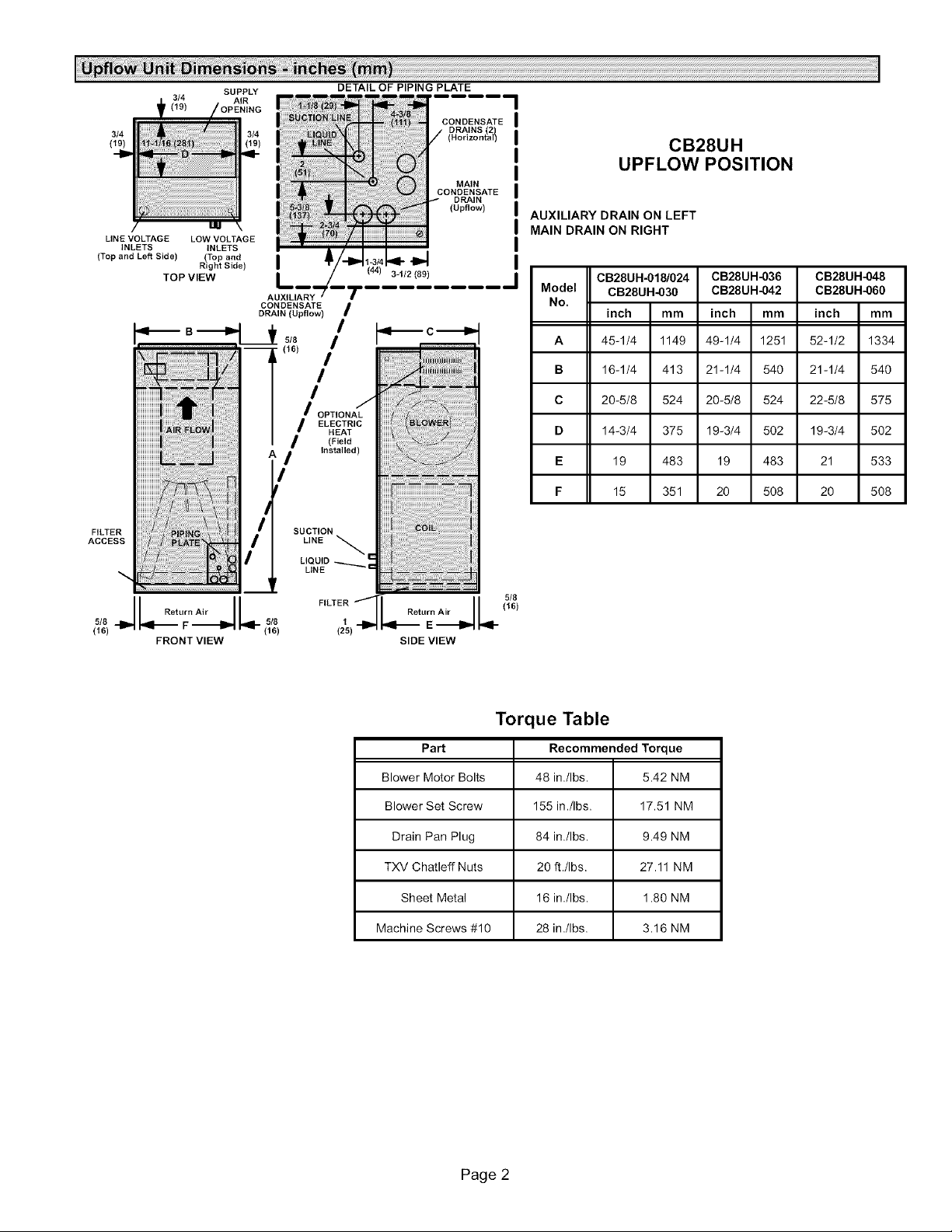
UPFLOW POSITION
AUXILIARY DRAIN ON LEFT
MAIN DRAIN ON RIGHT
Model
5/8
CB28UH-018/024
No.
A 1334
B 540
C 575
D 502
E 533
F 508
CB28UH-030
inch mm
45-1/4 1149
16-1/4 413
20-5/8 524
14-3/4 375
19 483
15 351
CB28UH
CB28UH-036
CB28UH-042
inch mm
49-1/4 1251
21-1/4 540
20-5/8 524
19-3/4 502
19 483
20 508
CB28UH-048
CB28UH-060
inch
52-1/2
21-1/4
22-5/8
19-3/4
21
2O
mm
Torque Table
Part Recommended Torque
Blower Motor Bolts 48 in./Ibs. 5.42 NM
Blower Set Screw 155 in./Ibs. 17.51 NM
Drain Pan Plug 84 in./Ibs. 9.49 NM
TXV Chatleff Nuts 20 ft./Ibs. 27.11 NM
Sheet Metal 16 in Jibs. 1.80 NM
Machine Screws #10 28 in./Ibs. 3.16 NM
Page 2
Page 3
DETAIL OF PIPING PLATE
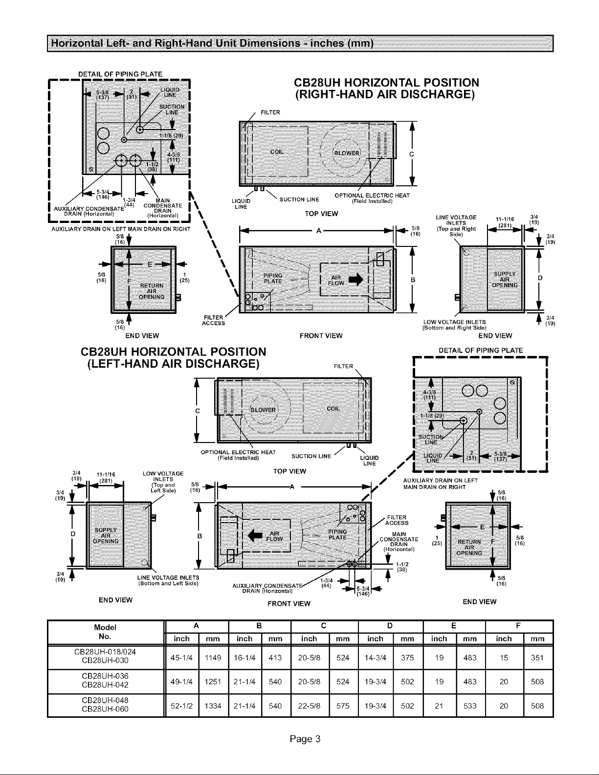
CB28UH HORIZONTAL POSITION
(RIGHT-HAND AIR DISCHARGE)
FILTER
C
I
AUXILIARY CONDENSATE ( ) C ONDDREN SATE I\
I DRAIN (Horizontal) (Horizontal) I \
CB28UH HORIZONTAL POSITION
(LEFT-HAND AIR DISCHARGE)
3/4
(19)
3/4 f(19)
1;;, MAN 5
5/8 1 \
(16) (25) \
5/8 ACCESS
(16)
END VIEW
11-1/t6 LOW VOLTAGE TOP VIEW
INLETS
(Top and si8 -=114
LeftSide)/ (16) --II A
LIQUID
LINE
\
\
4
\
\
FILTER
C
OPTIONAL ELECTRIC HEAT
(Field Installed) SUCTION LINE
SUCTION LINE (Field installed)
TOP VIEW
FRONT VIEW
OPTIONAL ELECTRIC HEAT
A
FILTER
LIQUID
LINE
;l#p f AUXILIARY DRAIN ON LEFT
LINE VOLTAGE
INLETS
(16) Side)
all= _I- 518 (Top and Right
B
LOW VOLTAGE INLETS
(Bottom and Right Side)
DETAIL OF PIPING PLATE
END VIEW
I- .......... 1
/
MAIN DRAIN ON RIGHT
11-1/16
3/4
(19)
f 3/4
f
D
.__1
(19)
FILTER
3/4
(19)
D
............ I
Model
END VIEW
No.
LINE V )LTAGE INLETS
(Bottom and Left Side)
inch mm inch mm inch mm inch mm inch mm inch mm
B
AUXILIARY
DRAIN
FRONT VIEW
A B C D E F
MAIN
CONDENSATE 215 518
DRAIN ( ) (16)
(Horizontal)
END VIEW
CB28UH-018/024
CB28UH-030 45-1/4 1149 16-1/4 413 20-5/8 524 14-3/4 375 19 483 15 351
CB28UH-036
CB28UH-042 49-1/4 1251 21-1/4 540 20-5/8 524 19-3/4 502 19 483 20 508
CB28UH-048
CB28UH-060 52-1/2 1334 21-1/4 540 22-5/8 575 19-3/4 502 21 533 20 508
Page 3
(16)
518
Page 4
InstallationofLennoxblowercoilunitswithorwithoutop-
tionalelectricheatmustconformwithstandardsintheNa-
tionalFireProtectionAssociation(NFPA)"Standardfor
InstallationofAirConditioningandVentilationSystems
NFPANo,90A,"and"StandardforInstallationof Resi-
denceTypeWarmAirHeatingandAirConditioningSys-
temsNFPANo.90B,"manufacturer'sinstallationinstruc-
tionsandlocalmunicipalbuildingcodes,
Thisunitiscertifiedforinstallationclearancestocombus-
tiblematerialaslistedontheunitratingplate,
CB28UHunitsarefactory-configuredforupfloworhori-
zontalright-handdischargeinstallation,Forhorizontal
left-handdischarge,somefieldmodificationisrequired.
ACAUTION
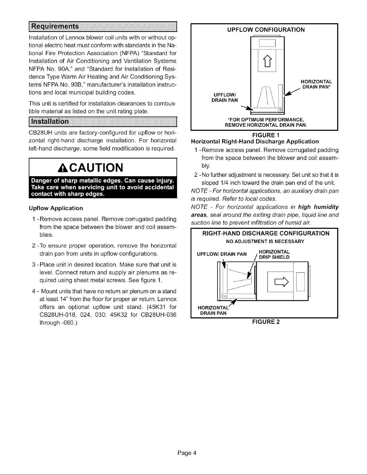
Upflow Application
1 - Remove access panel. Remove corrugated padding
from the space between the blower and coil assem-
blies.
2 -To ensure proper operation, remove the horizontal
drain pan from units in upflow configurations,
3 -Place unit in desired location. Make sure that unit is
level. Connect return and supply air plenums as re-
quired using sheet metal screws, See figure 1,
UPFLOW CONFIGURATION
9
HORIZONTAL
DRAIN PAN*
UPFLOW/
DRAIN PAN
.e
*FOR OPTIMUM PERFORMANCE,
REMOVE HORIZONTAL DRAIN PAN.
FIGURE 1
Horizontal Right-Hand Discharge Application
1 -Remove access panel. Remove corrugated padding
from the space between the blower and coil assem-
bly.
2 -No further adjustment is necessary. Set unit so that it is
sloped 1/4 inch toward the drain pan end of the unit.
NOTE - For horizontal applications, an auxiliary drain pan
is required. Refer to local codes.
NOTE - For horizontal applications in high humidity
areas, seal around the exiting drain pipe, liquid line and
suction line to prevent infiltration of humid air.
RIGHT-HAND DISCHARGE CONFIGURATION
NO ADJUSTMENT IS NECESSARY
UPFLOW/DRAIN PAN HORIZONTAL
4 - Mount units that have no retum air plenum on a stand
at least 14" from the floor for proper air return. Lennox
offers an optional upflow unit stand. (45K31 for
CB28UH-018, 024, 030; 45K32 for CB28UH-036
through -060.)
DRAIN PAN
FIGURE 2
Page 4
Page 5
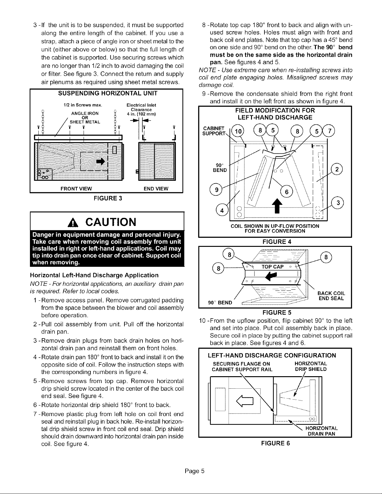
3-If theunitisto besuspended,itmustbesupported
alongtheentirelengthofthecabinet.If youusea
strap,attachapieceofangleironorsheetmetaltothe
unit(eitheraboveorbelow)sothatthefulllengthof
thecabinetissupported.Usesecuringscrewswhich
arenolongerthan1/2inchtoavoiddamagingthecoil
orfilter,Seefigure3.Connectthereturnandsupply
airplenumsasrequiredusingsheetmetalscrews,
SUSPENDINGHORIZONTALUNIT
1/2 in Screws max. Electrical Inlet
SHEET METAL
I I I
tl " I I II
FRONT VIEW END VIEW
FIGURE 3
Clearance
8 -Rotate top cap 180°front to back and align with un-
used screw holes, Holes must align with front and
back coil end plates. Note that top cap has a 45° bend
on one side and 90° bend on the other. The 90° bend
must be on the same side as the horizontal drain
pan. See figures 4 and 5,
NOTE - Use extreme care when re-installing screws into
coil end plate engaging holes. Misaligned screws may
damage coil.
9 -Remove the condensate shield from the right front
and install it on the left front as shown in figure 4,
FIELD MODIFICATION FOR
LEFT-HAND DISCHARGE
CABINET
90°
BEND
CAUTION
Horizontal Left-Hand Discharge Application
NOTE - For horizontal applications, an auxiliary drain pan
is required. Refer to local codes.
1 - Remove access panel. Remove corrugated padding
from the space between the blower and coil assembly
before operation.
2-Pull coil assembly from unit, Pull off the horizontal
drain pan,
3 -Remove drain plugs from back drain holes on hori-
zontal drain pan and reinstall them on front holes.
4 -Rotate drain pan 180° front to back and install it on the
opposite side of coil. Follow the instruction steps with
the corresponding numbers in figure 4.
5-Remove screws from top cap, Remove horizontal
drip shield screw located in the center of the back coil
end seal. See figure 4,
6 -Rotate horizontal drip shield 180° front to back.
7-Remove plastic plug from left hole on coil front end
seal and reinstall plug in back hole. Re-install horizon-
tal drip shield screw in front coil end seal, Drip shield
should drain downward into horizontal drain pan inside
coil, See fgure 4,
COIL SHOWN IN UP-FLOW POSITION
FOR EASY CONVERSION
FIGURE 4
/
BACK COIL
90 ° BEND
FIGURE 5
10 -From the upflow position, flip cabinet 90° to the left
and set into place. Put coil assembly back in place,
Secure coil in place by putting the cabinet support rail
back in place, See figures 4 and 6,
LEFT-HAND DISCHARGE CONFIGURATION
SECURING FLANGE ON HORIZONTAL
CABINET SUPPORT RAIL DRIP SHIELD
FIGURE 6
END SEAL
HORIZONTAL
DRAIN PAN
Page 5
Page 6

NOTE - For horizontal applications in high humidity
areas, seal around the exiting drain pipe, liquid line and
suction line to prevent infiltration of humid air.
11 -Knock out drain seal plate from access door. Secure
plate to cabinet front flange with screw provided,
12 -Flip access door and replace it on the unit,
13 -Set unit so that it is sloped 1/4 inch toward the drain
pan end of the unit, Connect return and supply air ple-
nums as required using sheet metal screws,
14 -If you are going to suspend the unit, the entire length
of the cabinet must be supported. If you use a chain
or strap, attach a piece of angle iron or sheet metal to
the unit (either above or below it), so that the full
length of the cabinet is supported. Use securing
screws which are no longer than 1/2 inch to avoid
damaging the coil or filter, See figure 3. Use sheet
metal screws to connect the return and supply air
plenums,
All CB28UH coils are equipped with a factory-installed, in-
ternally mounted expansion valve. Use Lennox L15
(sweat) series line sets as shown in table 1 or use field-
fabricated refrigerant lines, L10 (flare) line sets may be
used by cutting off flare nut. Refer to the piping section of
the Lennox Unit Information Service Manual for proper
size, type and application of field-fabricated lines,
TABLE 1
REFRIGERANT LINE KITS
CB28UH
UNIT
-018/-024
-030/-036
-042/-048
-060
LIQUID
LINE
3/8 in 5/8 in
(8 ram) (16 ram)
3/8 in 3/4 in,
(10 mm) (19 mm
3/8 in 7/8 in.
(10 ram) (22 ram)
3/8 in
(10 mm)
VAPOR
LINE
1-1/8 in,
(29 ram)
L15
LINE SETS
L15-26
20 ft, - 50 ft,
(6 m - 15 m)
L15-41
20 ft, - 50 ft,
(6 m - 15 m)
L15-65
30 ft. - 50 ft,
(9 m - 15 m)
FIELD
FABRICATED
NO TE - CB28UH series evaporators use nitrogen or dry
air as a holding charge. If there is no pressure when the
rubber plugs are removed, check the coil or line set for
leaks before installing. After installation, pull a vacuum
on the line set and coil before releasing the unit charge
into the system.
1 - Use a wet rag to protect TXV bulb (or remove it) when
brazing suction line,
2 - Be aware of filter access panel when connecting
lines, Filter must be accessible,
3 - Place heat shield (damp rag) against the piping plate
and around the suction line connection, Heat shield
must be in place to guard against damage to the
paint,
4 - With heat shield in place, sweat in the suction line
connection to the line set. After procedure is com-
pleted, remove heat shield,
5 - Place heat shield against piping plate and around the
liquid line connection, Sweat in the liquid line con-
nection to the line set,
6 - Refer to instructions provided with outdoor unit for
leak testing, evacuating and charging procedures.
Connect main condensate drain and route downward to
an open drain or sump, Do not connect drain to a closed
waste system, Refer to figure 7 for typical condensate
trap configuration,
TYPICAL CONDENSATE DRAIN CONNECTION
MINIMUM 1 INCH (25 ram) PIPE DIAMETER
PITCH PER 10 FEET J DIFFERENCE
(3048 ram) OF LINE _ COIL
Trap must be deep enough to offset maximum static
difference (Generally, 2 inches [51ram] minimum).
DRAIN PAN
FIGURE 7
It is recommended that the auxiliary drain be connected to
a drain line for all units. If auxiliary drain is not connected,
it must be plugged with provided cap, See figure 8 for aux-
iliary and main drain locations,
LEFT-HAND UPFLOW RIGHT-HAND
DISCHARGE DISCHARGE
[ I
ool oo % ................................................................................
AUXILIARY DRAIN ON LEFT MAIN DRAIN ON RIGHT
FIGURE 8
The following practices are recommended to ensure con-
densate removal:
1 -Drain piping should not be smaller than the drain con-
nections at drain pan,
2 -A trap must be installed in the main drain line,
3 -The trap must be deep enough to offset the difference
in static pressure between drain pan and atmo-
sphere, Generally, two inches is satisfactory for me-
dium static applications.
4 -Horizontal runs must be sloped 1 inch per 10 feet of
drain line to offset friction,
5 -An open vent in drain line will sometimes be required to
prevent vapor lock.
Page 6
Page 7

6-Drainsshouldbeconstructedinamannertofacilitate
futurecleaningandnotinterferewithfilteraccess.
Seefigure7.
7-Auxiliarydrainshouldruntoanareawherehome-
ownerwillnoticeitdraining.Refertolocalcodes.
8-Alldrainconnectionsthatarenotusedduringinstalla-
UNIT MODEL NO.
CB28UH-018/-024 15 x 20 (381 x 508)
CB28UH-030/-042 20 x 20 (508 x 508)
CB28UH-048/-060 20 x 22 (508 x 559)
tionmustbepluggedandproperlytorquedto7ft.Ibs.
topreventleaks.
It is very important to seal the unit so that warm air is not
allowed into the cabinet. Warm air introduces moisture,
which results in condensation problems. This is especial-
ly important when the unit is installed in an unconditioned
area.
A IMPORTANT
Make sure the liquid line and suction line entry points are
sealed with either the provided material or with Perma-
gum. Permagum may also be used to seal around the
main and auxiliary drains and around open areas of elec-
trical inlets.
Each unit includes a factory-installed filter. Note that filter
access cover fits over access panel.
Filters should be inspected monthly and must be cleaned
or replaced when dirty to assure proper operation.
This unit is equipped with standard throw-away type filters
which should be replaced when they become dirty.
To remove filter, take off filter access door, slide filter out of
the guides on either side of cabinet, insert new filter and
replace the filter access door. See table 2 for replacement
filter sizes.
TABLE3
CB28UH-018/024 BLOWER PERFORMANCE (208/230v)
External Static Pressure
Low Medium High
in. w.g.
.00
.05
.10
.15
.20
.25
.30
.40
.50
.60
.70
.75
NOTE -AII air data is measured external to unitwith air filter in place. Electric heaters have no appreciable air resistance.
Pa cfm L/s Watts cfm L_ Watts cfm L/s Watts
0 700 330 245 895 420 310 1030 485 375
10 690 325 240 875 415 305 1010 475 370
25 680 320 235 865 410 300 990 470 365
35 665 315 230 850 400 290 970 460 355
50 655 310 225 830 390 285 955 450 350
60 640 300 220 810 385 280 925 440 345
75 625 295 220 795 375 270 900 425 335
100 595 280 210 750 355 255 850 400 320
125 555 260 195 700 330 240 800 380 305
150 510 240 185 640 300 225 725 340 290
175 395 185 165 ............ 620 295 265
185 ........................ 570 270 255
Air Volume and Motor Watts at Specific Blower Taps
Minimum Blower Speeds (With Electric Heaters)
For the minimum allowable speed for the CB28UH series
units with electric heat, refer to the ECB29 installation in-
structions.
Air Volume Adjustment
Blower speed selection is accomplished by changing the
taps at the harness connector at the blower motor. Refer
to unit wiring diagram in figure 9. Refer to tables 3 through
8 for blower performance data.
TABLE 2
FILTER DIMENSIONS
FILTER SIZE
Inches (mm)
Page 7
Page 8

External Static
Pressure
in. w.g. Pa
,00 0
.05 10
.10 25
.15 35
.20 50
.25
.30
.40
.50
.60
.70
.75
NOTE-Att airdata is measured
External Static
Pressure
in. w.g.
.00
.05
.10
.15
.20
.25
.30
.40
.50
.60
.70
.75
NOTE -Att air data is measured
External Static
Pressure
in, w.g.
.00
.05
.10
.15
.20
.25
.30
.40
.50
.60
.70
.80
NOTE- Allairdataismeasured
TABLE 4
CB28UH-030 BLOWER PERFORMANCE (208/230v)
Air Volume and Motor Watts at Specific BlowerTaps
Low Medium High
cfm L/s Watts cfm L_ Wa_s cfm L/s Watts
1015 480 385 1135 535 410 1230 580 450
995 470 375 1120 530 400 1205 570 445
980 465 365 1095 515 390 1190 560 440
960 455 355 1075 505 380 1165 550 430
945 445 345 1050 495 375 1140 540 425
6O
75
100
125
150
175
185
extemaIto unitwith
925 435 335 1025 485 365 1105 520 415
900 425 325 1005 475 355 1080 510 405
860 405 305 950 450 335 1025 485 390
800 380 285 890 420 315 960 450 370
740 350 265 810 385 290 875 415 350
670 315 240 735 345 270 790 375 330
610 290 225 675 320 255 725 340 315
airfilterin place.Electricheatershaveno appreciableairresistance.
TABLE 5
CB28UH-036 BLOWER PERFORMANCE (208/230v)
Air Volume and Motor Wa_s at Specific Blower Taps
Low Medium High
Pa cfm L/s Watts cfm L_ Watts cfm L/s Watts
0 935 440 420 1145 540 510 1505 710 655
10 930 440 415 1140 535 500 1485 700 640
25 925 435 410 1130 535 490 1475 695 630
35 915 435 395 1125 530 480 1455 685 615
50 910 430 390 1115 525 475 1435 680 600
60 905 425 380 1110 525 465 1420 670 585
75 900 425 370 1100 520 455 1395 660 570
100 885 415 355 1080 510 430 1350 640 540
125 865 410 335 1060 500 415 1300 615 510
150 845 400 315 1030 485 390 1235 585 480
175 820 390 300 ............ 1160 550 455
185 ........................ 1015 480 425
extemaIto unitwith airfilterin place.Electricheatershaveno appreciableairresistance.
TABLE 6
CB28UH-042 BLOWER PERFORMANCE (208/230v)
Air Volume and Motor Wa_s at Specific Blower Taps
Low Medium High
Pa cfm L/s Watts cfm L_ Watts cfm L/s Watts
0 1295 610 520 1520 720 595 1775 840 730
10 1275 605 510 1505 710 585 1750 825 720
25 1255 590 495 1480 700 570 1720 810 710
35 1230 580 480 1455 685 555 1690 795 700
50 1215 575 470 1430 675 540 1650 780 685
60 1195 565 455 1405 665 525 1620 765 675
75 1170 555 440 1380 650 515 1595 750 660
100 1125 530 415 1320 625 485 1515 715 635
125 1065 500 385 1260 595 460 1420 670 605
150 1005 475 360 1175 555 425 1325 625 575
175 910 430 330 1075 505 395 1210 570 545
200 ........................ 900 425 480
external to unit with air filter in place. Electric heaters have no appreciable air resistance.
Page 8
Page 9

TABLE 7
CB28UH-048 BLOWER PERFORMANCE (208/230v)
External Static
Pressure
in. w.g. Pa
.00 0
.05 10
.10 25
.15 35
.20 50
.25 60
.30 75
.40 100
.50 125
.60 150
.70 175
.75 185
NOTE- Altair datais measuredextemaIto unitwithair filterin place.Etectdcheatershaveno appreciableairresistance.
External Static
Pressure
in. w.g. Pa
.00 0
.05 10
.10 25
.15 35
.20 50
.25 60
.30 75
.40 100
.50 125
.60 150
.70 175
.80 200
.90 225
.95 235
NOTE - All air data is measured external to unitwith air filter in place. Electric heaters have no appreciable air resistance.
cfm L/s Watts cfm L/s Watts cfm L/s Watts cfm L/s Watts cfm L/s Watts
1570 740 575 1800 850 700 2005 945
1550 730 570 1780 840 690 1980 935
1530 725 560 1760 830 680 1950 920
1520 715 560 1735 820 670 1930 910
1495 705 550 1710 805 660 1910 900
1475 695 545 1690 795 655 1880 890
1460 690 540 1670 785 650 1855 875
1415 670 530 1615 760 630 1795 850
1370 645 520 1560 735 615 1735 820
1310 620 505 1495 705 595 1670 790
1250 590 490 1425 675 575 1600 755
1175 555 470 1360 640 560 1520 715
1025 485 440 1280 605 545 1420 670
cfm L/s Wat_ cfm L_ Wa_s cfm L/s Wat_
1590 750 665 1790 845 805 2055 970 1005
1570 740 660 1770 835 790 2035 960 995
1555 735 655 1750 825 785 2005 945 980
1530 720 645 1730 815 775 1980 935 970
1510 710 640 1710 805 765 1945 920 955
1485 700 635 1685 795 755 1915 905 940
1460 690 625 1660 785 745 1885 890 930
1415 670 615 1610 760 725 1820 860 900
1370 645 600 1550 730 705 1750 825 875
1310 620 580 1490 705 685 1670 790 845
1240 585 560 1405 665 660 1575 745 820
1210 570 550 1360 640 645 1520 720 800
CB28UH-060 BLOWER PERFORMANCE (208/230v)
Low Medium-Low Medium Medium-High High
Low Medium High
1240 585 535 1365 645
Air Volume and Motor Wa_s at Specific Blower Taps
TABLE 8
Air Volume and Motor Watts at Specific Blower Taps
825 2135 1005 930 2245 1060 1080
815 2110 995 925 2220 1050 1070
805 2080 985 915 2190 1035 1060
795 2055 970 905 2165 1020 1050
790 2025 955 895 2135 1010 1040
780 1995 940 885 2105 995 1030
770 1965 930 875 2075 980 1020
750 1910 900 855 2005 945 995
730 1850 875 835 1935 910 975
710 1780 840 810 1855 875 950
690 1705 805 785 1780 840 925
665 1620 765 755 1685 795 900
645 1520 715 725 1595 750 875
630 1460 690 705 1545 730 860
Page 9
Page 10

WiringmustconformtothecurrentNationalElectricCode
ANSI/NFPANo.70,orCanadianElectricCodePartI,
CSAStandardC22.1,andlocalbuildingcodes.Referto
followingwiringdiagrams.Seeunitnameplateformini-
mumcircuitampacityandmaximumovercurrentprotec-
tionsize.
Selectthe propersupplycircuitconductorsinaccor-
dancewithtables310-16and310-17intheNational
ElectricCode,ANSI/NFPANo.70ortables1through4
in theCanadianElectricCode,PartI, CSAStandard
C22.1.
Thisunitisprovidedwithknockoutforconduit.Referto
figure9for unitschematicwiringdiagram.
Separateopeningshavebeenprovidedfor24Vlowvolt-
ageandlinevoltage.Referto thedimensionillustration
forspecificlocation.
,A WARNING
Page 10
Page 11
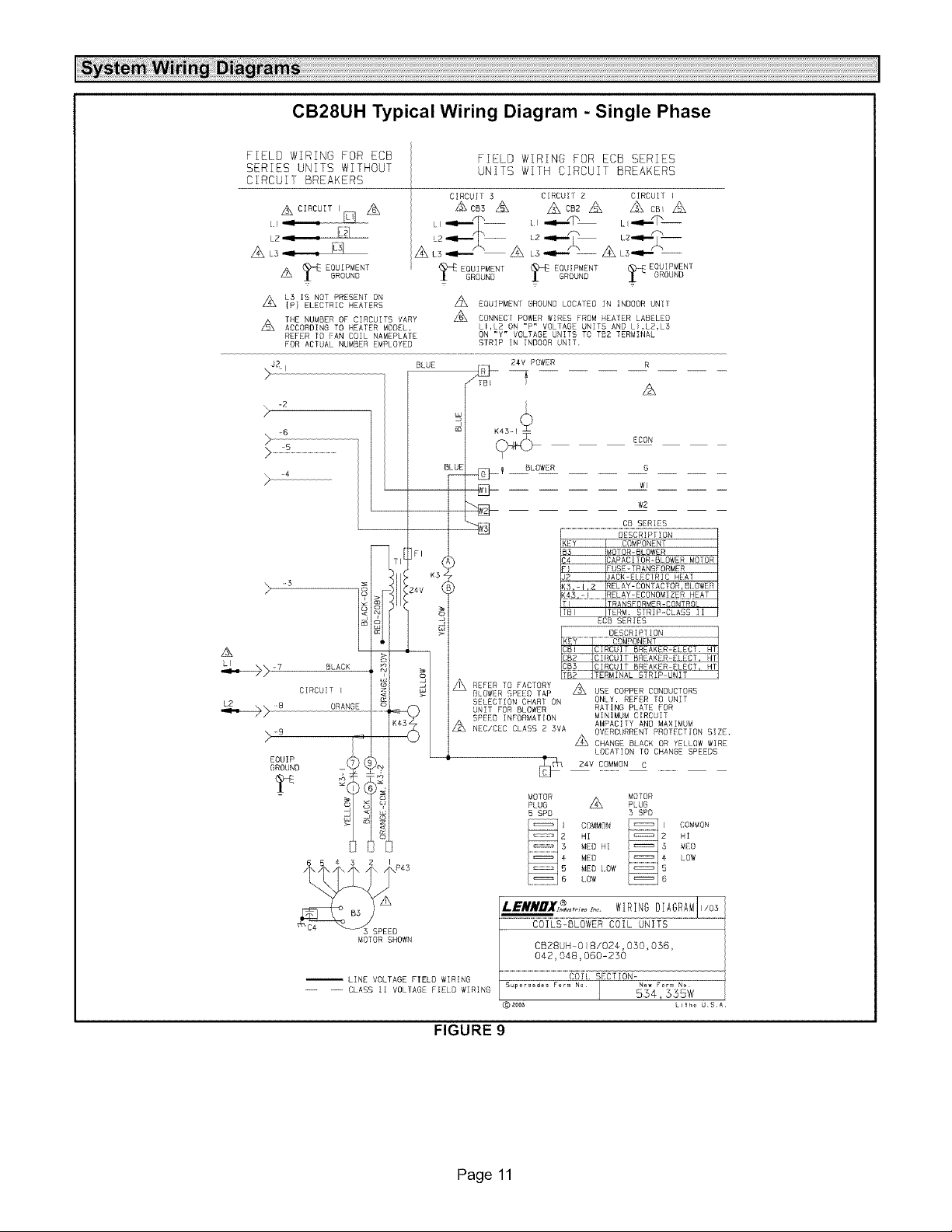
CB28UH Typical Wiring Diagram - Single Phase
FIELD WIRING FOR ECB
SERIES UNITS WITHOUT
CIRCUI[ BREAKERS
LB= : li_1
A L3= . g_
EQUIPMENT
A _ GROUND
A L5 IS NOT PRESENT ON
Z_
IP} ELECTRIC HEATERS
THE NUMBER OF CIRCUITS VARY
A ACCOROING TO HEATER MODEL,
REFER TR FAN EDIL NAMEPLATE
FOR ACTUAL NUMBER EMPLOYED
. -B
k
>_
> 4
>:_ ...................................................!
FIELD WIRING FOR ECB SERIES
UNITS WITH CIRCUIT BREAKERS
CIRCUIT 5 CIRCUII Z CIRCUI] ]
AcB3 A Z_cBzA A cB A
I =ill....i=ill....i_ -- .II...._ m L .,I.IIT m
A
ZB_ EQUIPMENI GROUND LOCATED IN INDOOR UNIf
A CONNECT POWER WIRES FROM HEALER LABELED
LI,L2 ON "P" VOLTAGE UNITS AND LI,L2,L3
ON "Y" VOLTAGE UNITS TO TB2 TERMINAL
STRIP IN INDOOR UNIT.
BLUE /_
d
24V POWER R
A
ICON
MOTOR SHOWN
-- LINE VOLTAGE FIELO WIRING
-- -- CLASS II VOLTAGE FIELD WIRING
FIGURE 9
Page 11
@ aoo_
MOTOR
PLUG
5 SPD
LOCATION TO CHANGE SPEEDS
MOTOR
A PLUG
COMMON COMMON
HI HI
MEO HI MED
MED LOW
MEO lOW
LOW
5 SPD
LH_o USA
Page 12

L2 LI COOLING ONLY APPLICATION
4i
K5 INDOOR
BLOWER RELAY
•--_-----L I (Black)
L2 (Orange)
CIRCUIT 1
FIELD-SUPPLIED
WIRE NUTS
TRANSFORMER
NOTE-USE COPPER
CONDUCTORS ONLY,
REFER TO UNIT RATING PLATE
FOR MINIMUM CIRCUIT AMPACITY
AND MAXIMUM OVERCURRENT
PROTECTION SIZE
GROUND
,ll
THERMOSTAT
_j I t_
F- l_
Ir
VV
L2 LI
IL
CIRCUIT
CIRCUIT BREAKERS
OR TERMINAL
BLOCK
©
LINE VOLTAGE FIELD INSTALLED
CLASS 2 VOLTAGE FIELD INSTALLED
NEC/CEC
l ._1 TERMI NAL
TBI I
I BLOCK
J
COOLING APPLICATION WITH ELECTRIC HEAT
K5 INDOOR
BLOWER RELAY
HEAT ELEMENT _1
K52
HEAT RELAY _1
TRANSFORMER FUSE
/_k TO EXTERNAL LOAD 24VAC
Z_ FACTORY INSTALLED JUMPERS
NOTE-ALL REMAINING WIRES
FACTORY INSTALLED
AT .50 AMP MAXIMUM
NOTE-USE COPPER
CONDUCTORS ONLY,
REFER TO UNIT RATING PLATE
FOR MINIMUM CIRCUIT AMPACITY
AND MAXIMUM OVERCURRENT
PROTECTION SIZE
NOTE-ALL REMAINING WIRES
FACTORY INSTALLED
LINE VOLTAGE FIELD INSTALLED
CLASS 2 VOLTAGE FIELD INSTALLED
NEC/CEC
',1--
/_ THERMOSTAT
j I L
r L_
Ir
VV
Ax
GROUND
TBI _)
TERMINALIO
BLOCK ' T
L.
_l I i _
t
I
J
. I
FIGURE 10
Page 12
==_
TO EXTERNAL LOAD 24VAC
AT .50 AMP MAXIMUM
THERMOSTAT HEAT ANTICIPATION
SETTING .4 AMP (ELECTRIC HEAT)
WHEN TWO STAGE THERMOSTAT IS USED
CONNECT SECOND STAGE HEAT BULB TO
TERMINAL "W2," AND REMOVE JUMPER
__1
BETWEEN TERMINALS "R" AND "W2."
Ak
FACTORY INSTALLED JUMPERS
L3 CONNECTION USED ON (Y VOLTAGE)
/k
3 PHASE ELECTRIC HEATERS ONLY.
Page 13

L2 I
l-
HEAT PUMP ONLY APPLICATION
K3 INDOOR
BLOWER RELAY
CIRCUIT 1
[]
[],A
CIRCUIT BREAKERS
OR TERMINAL
BLOCK
GROUND
CLASS 2 VOLIAGE FIELD INSIALLED
NEC/CEC
NOTE-ALL REMAINING WIRES FACTORY INSTALLED
TBI
TERMINAL
BLOCK
L
L
TRANSFORMER
FUSE
I
1
I I I I
/k] i i i
I I I
J I
I
w
_>
I I
I I
I I
I I
I I/
q[
u_
o
z
Z_TO EXTERNAL LOAD 24VAC AT .50 AMP MAXIMUM
Z_ FACTORY INSTALLED JUMPERS
/_Y2 USED ONLY WHEN TWO SPEED COMPRESSOR IS USED (HP21).
Z_ USING SERVICE LIGHT OPTION (S54) WITH SOME ELECTRONIC THERMO-
STATS MAY REQUIRE MOVING S54 COMMON WIRE TO Y1 IN HEAT PUMP
UNIT.
Z_ COMMON USED ONLY ON SOME THERMOSTATS.
Z_ AMBIENT COMPENSATING THERMISTOR CONNECTION USED ONLY ON SOME THERMOSTATS.
FIGURE 11
Page 13
HEAT PUMP CLASS 2
VOLTAGE TERMINALS
AA
Page 14

L2 LI
It
CIRCUIT
r_,A
CIRCUIT BREAKERS
OR TERMINAL
BLOCK
GROUND
HEAT ELEMENT 'I
K32
HEAT RELAY _1
_TBI
TERM[ NAL
BLOCK
K3 INDOOR
BLOWER RELAY
TRANSFORMER
©
/I
I
I
I
1
J
FUSE
A
HEAT PUMP APPLICATION
WITH ELECTRIC HEAT
CLASS 2 VOLTAGE FIELD INSTALLED
NEC/CBC
NOTE - ALL REMAINING WIRES ARE FACTORY INSTALLED
//_ THERMOSTAT HEATANTICIPATION
SETTING 0.4 AMP ELECTRIC HEAT
Z_ FACTORY INSTALLED JUMPERS
K22
EM HEAT RELAY
$23
0UTO00R
THERMOSTAT
(IF USED)
I I
I
'_( J i
I
T
t
I
/_ WHEN OUTDOOR THERMOSTAT tS USED, CONNECT LEADS TO TERMINALS
"R" AND "W2" AND REMOVE JUMPER BETWEEN TERMINALS "R' AND "W2."
Z_ EMERGENCY HEAT RELAY (USED ONLY tF OUTDOOR T'STAT IS USED) FIELD PROVIDED
AND INSTALLED NEW INDOOR UNIT, 24VAC 5VA MAX NEC/CEC CLASS 2
/_k USING SERVICE LIGHT OPTION ($54) WITH SOME ELECTRONIC THERMO-
STATS MAY REQUIRE MOVING $54 COMMON WIRE TO Y1 IN HEAT PUMP UNIT.
Z_ COMMON USED ONLY ON SOME THERMOSTATS.
z_Y2 USED ONLY WHEN TWO SPEED COMPRESSOR IS USED (HP21).
Z_ AMBIENT COMPENSATING THERMISTOR CONNECTION USED ONLY ON SOME THERMOSTATS.
SI
THERMOSTAT ,/_
-----
I I
]
1
I
.I
' Ii i
LO',,_
LnZ
c_n- N
i-- i--
,__j
cpcp pl
i II ,
o _ c,.
°°i
z,
FIGURE 12
Page 14
 Loading...