

Page 1
ENGINEERING DATA
COILS – BLOWER COIL UNITS
CB19 AND CBH19 SERIES
UP-FLOW, DOWN-FLOW AND HORIZONTAL
BLOWER COIL UNITS
*12,600 to 65,500 Btuh (3.7 to 19.2 kW) Cooling Capacity
11,500 to 60,000 Btuh (3.4 to 17.6 kW) Heat Pump Heating Capacity
6,400 to 102,400 Btuh (1.9 to 30.0 kW) Optional Electric Heat
*ARI Standard 210/240 Ratings With Matching Outdoor Unit
CB19/
CBH19
Bulletin #210056
January 1995
Supersedes
April 1994
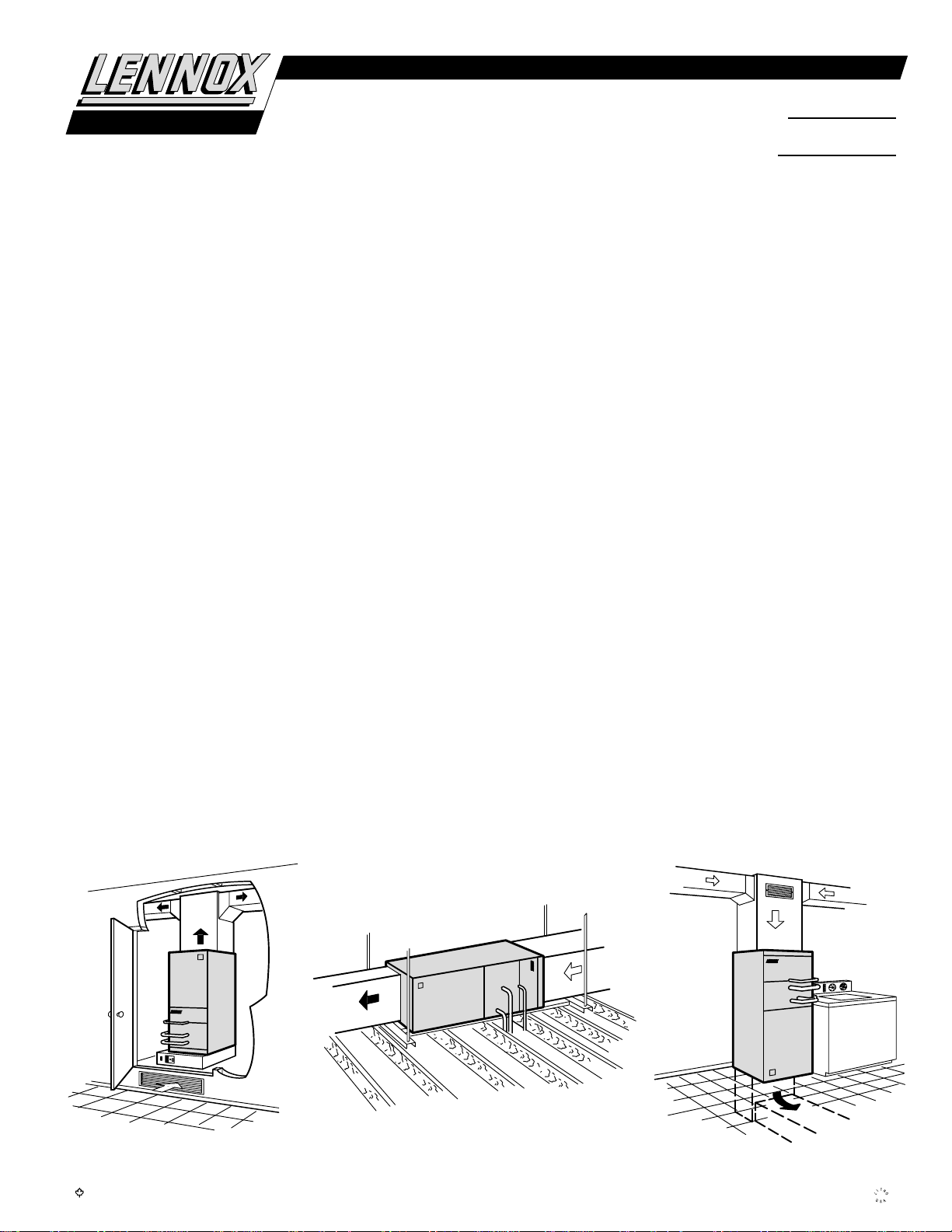
Applications —
signed for multi-position installation in a basement, utility
room, alcove, closet, crawlspace or attic. Units are applicable
to expansion valve systems in cooling applications and
check and expansion valve systems in heat pump applications. Units have factory installed check and expansion valve.
Several models are available in varying sizes with a wide
range of cooling and heating capacities. See Condensing Unit
bulletins in section Cooling Units — Condensing Units for
cooling capacities. See Heat Pump Outdoor Unit Bulletins in
section Heat Pumps — Matched Remote Systems for cooling
and heating capacities. Optional field installed electric heaters
are available in several sizes for additive heating capacity.
CB19 models are applicable to up-flow or down-flow discharge air applications. Units are shipped for up-flow applications and may easily be field converted to the downflow position by turning the unit upside down and
repositioning the coil, drip shields and cabinet access panel.
Filters are not furnished and must be provided by the installer. An optional side return air adapter with filter(s) is available for up-flow applications only. An optional additive
base is available for models with electric heat installed in
the down-flow position on combustible floors.
CBH19 models are designed for horizontal discharge air applications. Units are furnished with left hand air discharge as
standard and may be field changed to right hand discharge by
turning the unit over (end for end) and repositioning the coil.
CBH19-51 and CBH19-65 models are furnished in a two piece
cabinet with blower and optional electric heaters in one section and the indoor coil in the other. Hardware is furnished for
field connection of cabinets. Filters are not furnished and
must be provided by the installer.
The CB19 and CBH19 blower coil units are de-
CB19 MODEL — UP-FLO CB19 MODEL — DOWN-FLO
CBH19 MODEL — HORIZONTAL
Typical Applications
Horizontal Installation
Up-Flow Installation
with optional electronic air cleaner
The maple leaf symbol in this bulletin denotes Canadian only usage where applicable
NOTE — Due to Lennox’ ongoing committment to quality, Specifications, Ratings and Dimensions subject to change without notice and without incurring liability.
Down-Flow Installation
1995 Lennox Industries Inc.
Page 2

FEATURES
Completely Tested —
ing condensing units in the Lennox Research Laboratory environmental test room in accordance with ARI Standard
210/240-89. Optional electric heaters are rated in accordance
with U.S. Department of Energy (DOE) test procedures and
Federal Trade Commission (FTC) labeling regulations. Blower
performance data is according to actual unit tests conducted
in Lennox air test chamber. Blower-coil units and components
within are bonded for grounding to meet safety standards for
servicing required by U.L., C.S.A., CEC and NEC.
Cabinet —
completely insulated with thick fiberglass insulation. The prepainted steel cabinets have a finish of mildly textured enamel
with a primer coat on the unpainted side of all panels. Removable panels provide complete service access. Electrical inlets
are provided in both sides of cabinet. Return air entry is possible in either side or bottom of cabinet on up-flow units.
Drain Pan —
pipe drains extended outside of cabinet for ease of connection. See dimension drawings.
Constructed of heavy gauge galvanized steel and
Deep, corrosion resistant drain pan has dual
Direct Drive Blower —
built direct drive blower. Each blower is statically and dynamically balanced as an assembly before it is installed in the
unit. Multi-speed motor is resiliently mounted. A choice of
blower speeds is available. See blower performance tables.
Change of blower speeds is easily accomplished by a simple
change in wiring.
Refrigerant Line Connections —
lines have sweat connections and extend outside of the cabinet
for ease of connection. See dimension drawings for locations.
Check and Expansion Valve Furnished —
sion valve furnished and factory installed on all models.
Copper Tube/Enhanced Fin Evaporator Coil —
signed twin coils, assembled in a ‘V’ configuration, provides
extra large surface and contact area, excellent heat transfer
and low air resistance for maximum efficiency. Precise circuiting gives uniform refrigerant distribution. Lennox fabricated coil is constructed of precisely spaced ripple-edged aluminum fins fitted to durable seamless copper tubes. Fins are
strengthened to resist bending and are equipped with collars
that grip tubing for maximum contact area. Lanced fins provide maximum exposure of fin surface to air stream. Flared
shoulder tubing joints and silver soldering provide tight, leakproof joints. Long life copper tubing is easy to field service.
Coil is thoroughly factory tested under high pressure to insure leakproof construction.
Transformer and Blower Cooling Relay —
former and blower cooling relay are furnished as standard
equipment and are factory installed in the unit control box.
A terminal strip is also furnished as standard.
Blower coil units are tested with match-
Equipped with a Lennox designed and
Suction (vapor) and liquid
Check and expan-
Lennox de-
A 24 volt trans-
OPTIONAL ACCESSORIES (Must Be Ordered Extra)
Electric Heat (Optional) —
internal to the unit cabinet and are available in several kw sizes,
see Electric Heat table. The helix wound nichrome bare heating elements are exposed directly in the air stream resulting in
instant heat transfer, low element temperatures and long service life. Each heating element is equipped with accurately located limit control with fixed temperature off setting and automatic reset. In addition, elements have supplemental thermal
cutoff safety fuses providing positive protection in case of excessive temperatures. Cutoff fuses are mounted external to
the element face plate for quick and easy replacement. Thermal sequencer relay brings the heating elements on and off line,
in sequence and equal increments, with a time delay between
each element. Sequencer also initiates and terminates blower
operation. Heating control relay(s), is furnished as standard.
Control box and access cover are constructed of heavy gauge
galvanized steel. Heaters are factory assembled with controls
installed and wired and only require plug-in field connection.
Additive electric heaters field install
Circuit Breakers —
(208/240v-1ph) and ECB19-15,-20 and -25 kw (208/240v-3ph)
electric heaters are equipped with circuit breakers to provide
overload and short circuit protection. Breakers are factory
wired and mounted on electric heat unit. Circuit breakers are
current sensitive and temperature actuated to shut off heater if
current draw is excessive. Must be reset manually. Circuit
breakers qualify as the disconnect means at unit in many
areas and eliminate the need for a field provided disconnect.
Consult local electrical code in your area.
ECB19-12.5,-15,-20,-25 and -30 kw
Single-Point Power Source Control Box (Optional) —
Box (21H39) may be used with optional electric heat when
two or three circuits (if required by code) are specified. Field
installs external to the unit cabinet on either side or top. Provides single power service connection to the unit.
Constructed of heavy gauge steel with baked enamel finish,
prepunched mounting holes, electrical inlet knockouts, and
terminal strip. Removeable cover provides easy access.
Box is 7” x 7” x 4” deep (178mm x 178mm x 102mm), shipping
weight is 5 lbs. (2 kg.)
CCB1 EfficiencyPlus Humidity Control (Optional) —
CCB1 Humidity Control (35H00) is an electronic control which
installs next to the room thermostat and allows the selection of
the desired indoor humidity level in the cooling mode. During
the heating season the control is inoperable. The CCB1 controls
the indoor humidity by altering the indoor blower speed
and the compressor speed.
Humidity level desired may be
accomplished by adjusting a
vertical slide to a set point on
a scale of 40% thru 60% with
50% recommended as the initial set point. Five indicator
lights (MIN — MAX) in a bar
graph configuration indicate
the difference in the actual relative humidity and the set point. This indicates the demand
imposed on the system equipment, the more lights on, the
longer the equipment will operate to obtain the desired humidity level. If no lights are on, the humidity is at or below the
set point. Control is not furnished and must be ordered extra.
Requires EBR1 Blower Relay Kit
EBR1 Blower Relay Kit (Optional) —
(75H90) allows CCB1 to be used with CB19/CBH19 blower
coil units.
Down-Flow Additive Base (Optional) —
base is required for models with electric heat installed in the
down-flow position on combustible floors. Base is not furnished
and must be ordered extra for field installation. See Specifications table and dimension drawing.
Air Filters (Not Furnished) —
Specifications tables for sizes. Filter rails are provided in return
air opening of unit. See dimension drawings.
Filters must be ordered extra. See
EBR1 Blower Relay Kit
An optional additive
CB19 Up-Flow Side Return Air Filter Adaptor (Optional) —
Field installs on either side return air opening of up-flow cabinet. Constructed of heavy gauge galvanized steel with a bakedon paint finish. Equipped with flanges for ease of duct connection. Access panel allows easy removal an replacement of
filter(s). One inch thick (25mm) frame type filter is furnished as
standard. Media is washable or vacuum cleanable oil coated
polyurethane. CB19-21 thru 41 adaptor requires one filter.
CB19-51 and CB19-65 model has two. See Specification table
for sizes. CB19-51 and CB19-65 fiberglass insulated adaptor is
shipped knocked down and must be field assembled.
—2—
Control
The
Page 3
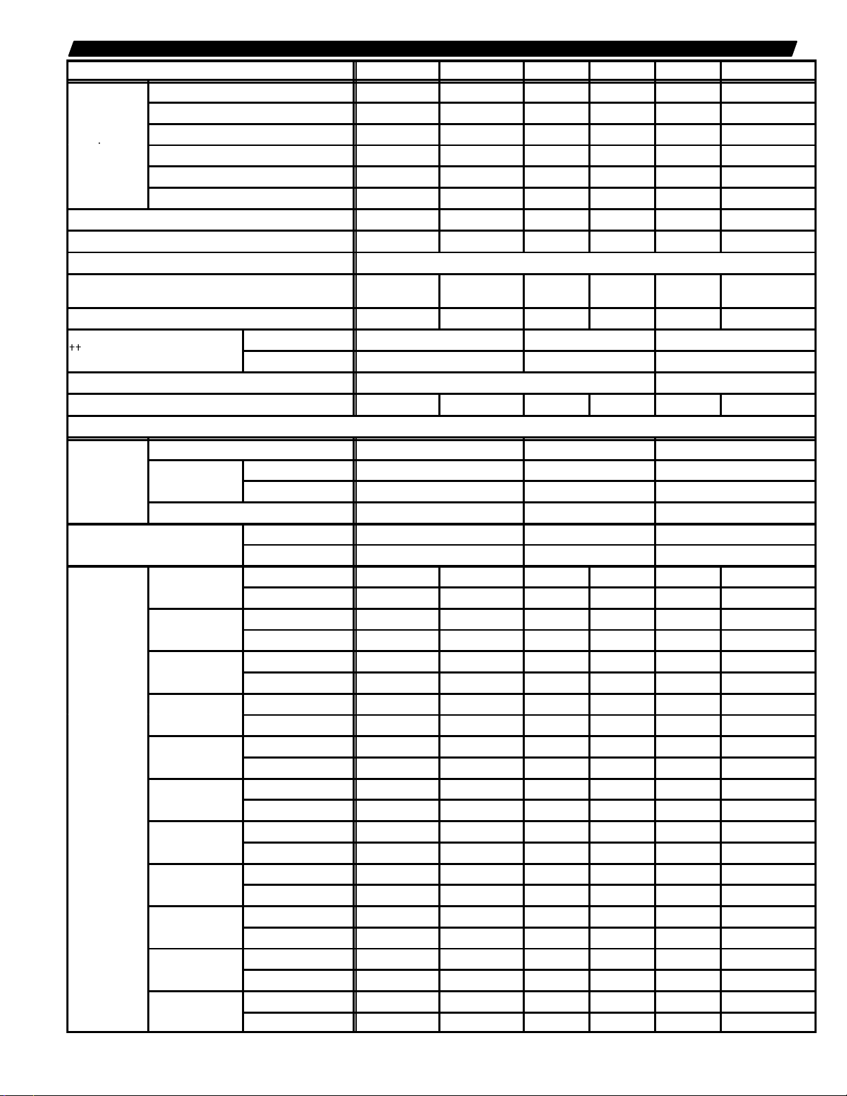
SPECIFICATIONS — CB19 UP-FLOW/DOWN-FLOW
p
{{Number and size of filters
Filter Adaptor
ECB19-2.5
ECB19-5
ECB19-6
ECB19-75
ECB19-8
Heat
ECB19-10
ECB19-12.5
ECB19-15
ECB19-20
ECB19-25
ECB19-30
Evaporator
Coil
Condensate drain connection (pvc) — in. (mm) (2) 3/4 (19) (2) 3/4 (19) (2) 3/4 (19) (2) 3/4 (19) (2) 3/4 (19) (2) 3/4 (19)
Nominal cooling capacity — tons (kW) 1-1/2 (5.3) 2 (7.0) 2-1/2 (8.8) 3 (10.6) 4 (14.1) 5 (17.6)
Refrigerant HCFC-22
Blower wheel nominal diameter x width — in. (mm)
Blower motor output — hp (W) 1/10 (75) 1/5 (149) 1/3 (149) 1/3 (249) 1/3 (249) 1/2 (373)
Electrical characteristics 208/230 volts — 60 hz — 1 ph 208/230/460 volt 60 hz – 1 ph
Shipping weight — lbs. (kg) 1 package 143 (65) 146 (66) 167 (76) 167 (76) 209 (95) 213 (97)
Side Return Air
(Up-Flow Only)
Down-Flow
Combustible Base
Electric
Capacity
{Annual Fuel Utilization Efficiency based on U.S. DOE test procedures and according to FTC labeling regulations
{{Filters are not furnished and must be ordered extra.
*Includes additional blower motor heat capacity.
Model Number CB19-21 CB19-26 CB19-31 CB19-41 CB19-51 CB19-65
Net face area — ft.2 (m2) 4.22 (0.39) 4.22 (0.39) 5.27 (0.49) 5.27 (0.49) 7.0 (0.65) 7.0 (0.65)
Tube outside diameter — in. (mm) 3/8 (9.5) 3/8 (9.5) 3/8 (9.5) 3/8 (9.5) 3/8 (9.5) 3/8 (9.5)
Number of rows 3 3 3 3 3 3
Fins per inch (fins per m) 12 (472) 12 (472) 13 (512) 13 (512) 14 (551) 14 (551)
Suct. (vapor) line conn. – in. (mm) sweat 5/8 (16) 5/8 (16) 3/4 (19) 3/4 (19) 7/8 (22.2) 1-1/8 (28)
Liquid line conn. — in. (mm) sweat 3/8 (9.5) 3/8 (9.5) 3/8 (9.5) 3/8 (9.5) 3/8 (9.5) 3/8 (9.5)
9 x 7
(229 x 178)
in. (1) 16 x 20 x 1 (1) 20 x 20 x 1 (1) 20 x 25 x 1
mm (1) 406 x 508 x 25 (1) 508 x 508 x 25 (1) 508 x 635 x 25
b Optional Accessories (Must Be Ordered Extra) b
Catalog number 95G73 95G74 95G75
Number and size
of filters
Shipping weight — lbs. (kg) 4 (2) 5 (2) 24 (11)
in. (1) 16 x 20 x 1 (1) 20 x 20 x 1 (2) 16 x 25 x 1
mm (1) 406 x 508 x 25 (1) 508 x 508 x 25 (2) 406 x 635 x 25
Catalog number 85G52 85G53 85G54
Ship. wt. – lbs. (kg) 8 (4) 8 (4) 8 (4)
*Output — Btuh (kW) 9,000 (2.6) 9,500 (2.8) - - - - - - - - - - - - - - - -
{A.F.U.E.
*Output — Btuh (kW) 18,000 (5.3) 18,000 (5.3) 18,000 (5.3) 18,000 (5.3) 19,000 (5.6) - - - -
{A.F.U.E.
*Output — Btuh (kW) 21,000 (6.2) 22,000 (6.4) 22,000 (6.4) 22,000 (6.4) 23,000 (6.7) - - - -
{A.F.U.E.
*Output — Btuh (kW) 25,000 (7.3) 25,000 (7.3) 25,000 (7.3) 25,000 (7.3) 26,000 (7.6) - - - -
{A.F.U.E.
*Output — Btuh (kW) 28,000 (8.2) 28,000 (8.2) 29,000 (8.5) 29,000 (8.5) 29,000 (8.5) 30,000 (8.8)
{A.F.U.E.
*Output — Btuh (kW) 35,000 (10.3) 35,000 (10.3) 35,000 (10.3) 35,000 (10.3) 36,000 (10.5) 37,000 (10.8)
{A.F.U.E.
*Output — Btuh (kW) - - - - 44,000 (12.9) 44,000 (12.9) 44,000 (12.9) 45,000 (13.2) 46,000 (13.5)
{A.F.U.E.
*Output — Btuh (kW) - - - - 52,000 (15.2) 52,000 (15.2) 53,000 (15.5) 53,000 (15.5) 54,000 (15.8)
{A.F.U.E.
*Output — Btuh (kW) - - - - - - - - - - - - 70,000 (20.5) 70,000 (20.5) 71,000 (20.8)
{A.F.U.E.
*Output — Btuh (kW) - - - - - - - - - - - - - - - - 87,000 (25.5) 88,000 (25.8)
{A.F.U.E.
*Output — Btuh (kW) - - - - - - - - - - - - - - - - - - - - 105,000 (30.8)
{A.F.U.E.
100% 100% - - - - - - - - - - - - - - - -
100% 100% 100% 100% 100% - - - -
100% 100% 100% 100% 100% - - - -
100% 100% 100% 100% 100% - - - -
100% 100% 100% 100% 100% 100%
100% 100% 100% 100% 100% 100%
- - - - 100% 100% 100% 100% 100%
- - - - 100% 100% 100% 100% 100%
- - - - - - - - - - - - 100% 100% 100%
- - - - - - - - - - - - - - - - 100% 100%
- - - - - - - - - - - - - - - - - - - - 100%
9 x 8
(229 x 203)
10 x 7
(254 x 178)
10 x 9
(254 x 229)
11 x 8
(279 x 203)
12 x 9
(317 x 229)
—3—
Page 4
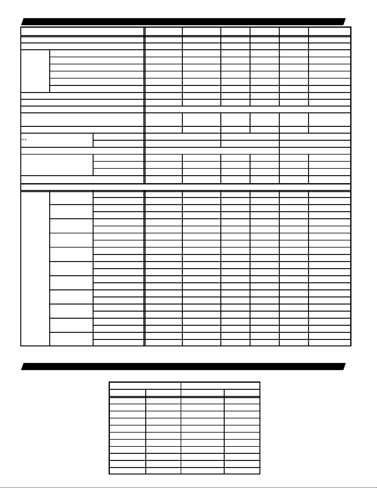
SPECIFICATIONS — CBH19 HORIZONTAL
{{Numb
fil
Shippi
ht
lbs. (kg)
ECB19-5
ECB19-6
ECB19-7
ECB19-8
Heat
y
ECB19-10
Capacity
ECB19-12.5
ECB19-15
ECB19-20
ECB19-25
ECB19-30
Model Number CBH19-21 CBH19-26 CBH19-31 CBH19-41 CBH19-51 CBH19-65
Blower section - - - - - - - - - - - - - - - - B19-51 B19-65
Indoor coil section - - - - - - - - - - - - - - - - CH19-51 CH19-65
Net face area — ft.2 (m2) 4.22 (0.39) 4.22 (0.39) 5.27 (0.49) 5.27 (0.49) 7.22 (0.67) 7.22 (0.67)
Tube outside diameter — in. (mm) 3/8 (9.5) 3/8 (9.5) 3/8 (9.5) 3/8 (9.5) 3/8 (9.5) 3/8 (9.5)
Evaporator
Coil
Condensate drain connection (mpt) — in. (mm) (2) 3/4 (19) (2) 3/4 (19) (2) 3/4 (19) (2) 3/4 (19) (2) 3/4 (19) (2) 3/4 (19)
Nominal cooling capacity — tons (kW) 1-1/2 (5.3) 2 (7.0) 2-1/2 (8.8) 3 (10.6) 4 (14.1) 5 (17.6)
Refrigerant HCFC-22
Blower wheel nominal diameter x width — in. (mm)
Blower motor output — hp (W) 1/10 (75) 1/5 (149) 1/3 (149) 1/3 (249) 1/3 (249) 1/2 (373)
Electrical characteristics 208/230v — 60 hz — 1 ph 208/230/460v 60 hz – 1 ph
Number of packages in shipment
Electric
Capacit
{Annual Fuel Utilization Efficiency based on U.S. DOE test procedures and according to FTC labeling regulations
{{Filters are not furnished and must be ordered extra.
*Includes additional blower motor heat capacity.
Number of rows 3 3 3 3 3 3
Fins per inch (fins per m) 12 (472) 12 (472) 13 (512) 13 (512) 14 (551) 14 (551)
Suct. (vapor) line conn. — in. (mm) sweat 5/8 (16) 5/8 (16) 3/4 (19) 3/4 (19) 7/8 (22.2) 1-1/8 (28)
Liquid line connection — in. (mm) flare 3/8 (9.5) 3/8 (9.5) 3/8 (9.5) 3/8 (9.5) 3/8 (9.5) 3/8 (9.5)
er and size of
ng weig
9 x 7
(229 x 178)
in. (1) 16 x 20 x 1 (1) 20 x 20 x 1 (1) 20 x 25 x 1
ters
mm (1) 406 x 508 x 25 (1) 508 x 508 x 25 (1) 508 x 635 x 25
Complete unit 149 (68) 149 (68) 176 (80) 178 (81) 240 (109) 242 (109)
Blower section - - - - - - - - - - - - - - - - 118 (54) 120 (54)
9 x 8
(229 x 203)
10 x 7
(254 x 178)
10 x 9
(254 x 229)
11 x 8
(279 x 203)
Coil section - - - - - - - - - - - - - - - - 122 (55) 122 (55)
1 1 1 1 2 2
b Optional Accessories (Must Be Ordered Extra) b
ECB19-2.5
*Output — Btuh (kW) 9,000 (2.6) 9,500 (2.8) - - - - - - - - - - - - - - - -
{A.F.U.E. 99.8% 99.8% - - - - - - - - - - - - - - - -
*Output — Btuh (kW) 18,000 (5.3) 18,000 (5.3) 18,000 (5.3) 18,000 (5.3) 19,000 (5.6) - - - -
{A.F.U.E. 99.7% 99.7% 99.9% 100% 100% - - - -
*Output — Btuh (kW) 21,000 (6.2) 22,000 (6.4) 22,000 (6.4) 22,000 (6.4) 23,000 (6.7) - - - -
{A.F.U.E. 99.7% 99.7% 99.9% 100% 100% - - - -
*Output — Btuh (kW) 25,000 (7.3) 25,000 (7.3) 25,000 (7.3) 25,000 (7.3) 26,000 (7.6) - - - -
{A.F.U.E. 99.7% 99.7% 99.9% 100% 100% - - - -
*Output — Btuh (kW) 28,000 (8.2) 28,000 (8.2) 29,000 (8.5) 29,000 (8.5) 29,000 (8.5) 30,000 (8.8)
{A.F.U.E. 99.7% 99.7% 99.8% 100% 100% 100%
*Output — Btuh (kW) 35,000 (10.3) 35,000 (10.3) 35,000 (10.3) 35,000 (10.3) 36,000 (10.5) 37,000 (10.8)
{A.F.U.E. 99.7% 99.7% 99.8% 99.9% 100% 100%
*Output — Btuh (kW) - - - - 44,000 (12.9) 44,000 (12.9) 44,000 (12.9) 45,000 (13.2) 46,000 (13.5)
{A.F.U.E. - - - - 99.5% 99.7% 99.9% 100% 100%
*Output — Btuh (kW) - - - - 52,000 (15.2) 52,000 (15.2) 53,000 (15.5) 53,000 (15.5) 54,000 (15.8)
{A.F.U.E. - - - - 99.5% 99.7% 99.9% 100% 100%
*Output — Btuh (kW) - - - - - - - - - - - - 70,000 (20.5) 70,000 (20.5) 71,000 (20.8)
{A.F.U.E. - - - - - - - - - - - - 99.8% 99.8% 100%
*Output — Btuh (kW) - - - - - - - - - - - - - - - - 87,000 (25.5) 88,000 (25.8)
{A.F.U.E. - - - - - - - - - - - - - - - - 99.8% 99.9%
*Output — Btuh (kW) - - - - - - - - - - - - - - - - - - - - 105,000 (30.8)
{A.F.U.E. - - - - - - - - - - - - - - - - - - - - 99.9%
12 x 9
(317 x 229)
BLOWER DATA
UP-FLOW SIDE RETURN AIR FILTER ADAPTOR RESISTANCE
Air Volume Filter Resistance
cfm L/s in. wg. Pa
400 190 .01 2
600 285 .02 5
800 380 .03 7
1000 470 .05 12
1200 565 .08 20
1400 660 .08 20
1600 755 .08 20
1800 850 .09 22
2000 945 .09 22
2200 1040 .10 25
2400 1135 .10 25
—4—
Page 5

BLOWER DATA
CB19-21 AND CBH19-21 BLOWER PERFORMANCE
External Static
Pressure
in. wg. Pa cfm L/s cfm L/s cfm L/s
0 0 855 405 630 295 530 250
.05 12 830 390 625 295 525 250
.10 25 800 380 620 295 520 245
.15 37 765 360 610 290 515 245
.20 50 730 345 595 280 505 240
.25 62 685 325 570 270 490 230
.30 75 640 300 535 250 465 220
.40 100 525 250 425 200 365 170
NOTE — All air data is measured external to unit.
Electric heaters have no appreciable air resistance.
For optional up-flow air filter resistance see separate table.
CB19-31 AND CBH19-31 BLOWER PERFORMANCE
External Static
Pressure
in. wg. Pa cfm L/s cfm L/s cfm L/s
0 0 1400 660 1270 600 1050 495
.05 12 1370 645 1250 590 1050 495
.10 25 1335 630 1220 575 1050 495
.15 37 1290 610 1190 560 1040 490
.20 50 1240 585 1150 545 1025 485
.25 62 1190 560 1110 525 1000 470
.30 75 1130 535 1060 500 970 460
.40 100 1000 470 945 445 885 420
.50 125 855 405 815 385 765 360
NOTE — All air data is measured external to unit.
Electric heaters have no appreciable air resistance.
For optional up-flow air filter resistance see separate table.
CB19-51 AND CBH19-51 BLOWER PERFORMANCE
External Static
Pressure
in. wg. Pa cfm L/s cfm L/s cfm L/s
0 0 1950 920 1640 775 1380 650
.05 12 1910 900 1620 765 1370 645
.10 25 1870 880 1600 755 1350 635
.15 37 1830 865 1580 745 1330 630
.20 50 1780 840 1550 730 1310 620
.25 62 1730 815 1520 715 1290 610
.30 75 1680 795 1490 705 1260 595
.40 100 1570 740 1400 660 1200 565
.50 125 1410 665 1280 605 1100 520
NOTE — All air data is measured external to unit.
Electric heaters have no appreciable air resistance.
For optional up-flow air filter resistance see separate table.
CB19-65 AND CBH19-65 BLOWER PERFORMANCE
External Static
Pressure
in. wg. Pa cfm L/s cfm L/s cfm L/s
0 0 2415 1140 2205 1040 1830 865
.05 12 2360 1115 2165 1020 1815 855
.10 25 2305 1090 2125 1005 1800 850
.15 37 2245 1060 2085 985 1780 840
.20 50 2185 1030 2040 965 1760 830
.25 62 2130 1005 2000 945 1735 820
.30 75 2070 975 1950 920 1705 805
.40 100 1940 915 1845 870 1630 770
.50 125 1810 855 1725 815 1540 725
.60 150 1665 785 1585 750 1405 665
NOTE — All air data is measured external to unit.
Electric heaters have no appreciable air resistance.
For optional up-flow air filter resistance see separate table.
Air Volume at Various Blower Speeds
High Medium Low
Air Volume at Various Blower Speeds
High Medium Low
WITH 208/230 VOLT MOTOR
Air Volume at Various Blower Speeds
High Medium Low
WITH 208/230 VOLT MOTOR
Air Volume at Various Blower Speeds
High Medium Low
CB19-26 AND CBH19-26 BLOWER PERFORMANCE
External Static
Pressure
in. wg. Pa cfm L/s cfm L/s cfm L/s
0 0 1150 545 1020 480 870 410
.05 12 1105 520 985 465 860 405
.10 25 1065 505 955 450 850 400
.15 37 1020 480 920 435 825 390
.20 50 960 455 875 415 795 375
.25 62 905 425 830 390 755 355
.30 75 845 400 780 370 710 335
.40 100 680 320 625 295 550 260
NOTE — All air data is measured external to unit.
Electric heaters have no appreciable air resistance.
For optional up-flow air filter resistance see separate table.
Air Volume at Various Blower Speeds
High Medium Low
CB19-41 AND CBH19-41 BLOWER PERFORMANCE
External Static
Pressure
in. wg. Pa cfm L/s cfm L/s cfm L/s
0 0 1630 770 1380 650 1130 535
.05 12 1590 750 1370 645 1150 545
.10 25 1550 730 1350 635 1160 545
.15 37 1500 710 1330 630 1160 545
.20 50 1460 685 1310 620 1160 545
.25 62 1400 660 1270 600 1150 545
.30 75 1340 630 1230 580 1130 535
.40 100 1200 565 1130 535 1050 495
.50 125 1010 475 960 455 890 420
NOTE — All air data is measured external to unit.
Electric heaters have no appreciable air resistance.
For optional up-flow air filter resistance see separate table.
Air Volume at Various Blower Speeds
High Medium Low
CB19-51 AND CBH19-51 BLOWER PERFORMANCE
WITH 460 VOLT (1 phase) MOTOR
External Static
Pressure
in. wg. Pa cfm L/s cfm L/s
0 0 2020 955 1630 770
.05 12 1950 920 1610 760
.10 25 1920 905 1600 755
.15 37 1870 880 1570 740
.20 50 1820 860 1540 725
.25 62 1770 835 1500 710
.30 75 1710 805 1460 690
.40 100 1590 750 1350 635
.50 125 1430 675 1250 590
NOTE — All air data is measured external to unit.
Electric heaters have no appreciable air resistance.
For optional up-flow air filter resistance see separate table.
Air Volume at Various Blower Speeds
High Low
CB19-65 AND CBH19-65 BLOWER PERFORMANCE
WITH 460 VOLT (1 phase) MOTOR
External Static
Pressure
in. wg. Pa cfm L/s cfm L/s
0 0 2380 1125 2250 1060
.05 12 2340 1105 2180 1030
.10 25 2290 1080 2140 1010
.15 37 2250 1060 2110 995
.20 50 2190 1035 2065 975
.25 62 2130 1005 2015 950
.30 75 2075 980 1970 930
.40 100 1945 920 1860 880
.50 125 1820 860 1760 830
NOTE — All air data is measured external to unit.
Electric heaters have no appreciable air resistance.
For optional up-flow air filter resistance see separate table.
—5—
Air Volume at Various Blower Speeds
High Low
Page 6

ELECTRIC HEAT DATA — CB19/CBH19-21,-26
Model Number
& Shipping Weight
Steps & Phase
Input
Input
Input
Amps
(68G86)
(g)
ECB19-5
(69G87)
g
ECB19-6
(69G88)
g
ECB19-7
(69G89)
g
ECB19-8
(69G90)
g
ECB19-10
(69G91)
g
ECB19-2.5
(69G86)
g
ECB19-5
(69G87)
g
ECB19-6
(69G88)
g
ECB19-7
(69G89)
g
ECB19-8
(69G90)
g
ECB19-10
(69G91)
g
ECB19-12.5
(69G92)
g
(69G93)
(g)
Blower Coil Unit
Electric Heat Model Number
Number of
Volts
kW
**Btuh
DBlower
Circuit 1 Circuit 2
ECB19-2.5
4 lbs. (2 kg)
4 lbs. (2 kg)
5 lbs. (2 kg)
CB19-21
CBH19-21
5 lbs. (2 kg)
5 lbs. (2 kg)
5 lbs. (2 kg)
4 lbs. (2 kg)
4 lbs. (2 kg)
5 lbs. (2 kg)
5 lbs. (2 kg)
CB19-26
CBH19-26
5 lbs. (2 kg)
5 lbs. (2 kg)
10 lbs. (5 kg)
ECB19-15
10 lbs. (5 kg)
*Refer to National or Canadian Electrical Code manual to determine wire, fuse and disconnect size requirements. Use wires suitable for at least 167°F (75_C).
**Electric heater capacity only — does not include additional blower motor heat capacity.
DMinimum circuit ampacity for blower motor only.
1 step
1 phase
1 step
1 phase
2 steps
1 phase
2 steps
1 phase
2 steps
1 phase
2 steps
1 phase
1 step
1 phase
1 step
1 phase
2 steps
1 phase
2 steps
1 phase
2 steps
1 phase
2 steps
1 phase
3 steps
1 phase
3 steps
1 phase
208 1.9 6,400 1.0 12.3 - - - 220 2.1 7,200 1.0 12.8 - - - 230 2.3 7,800 1.0 13.4 - - - 240 2.5 8,500 1.0 13.9 - - - -
208 3.8 12,800 1.0 23.5 - - - -
220 4.2 14,300 1.0 24.8 - - - 230 4.6 15,700 1.0 25.9 - - - 240 5.0 17,100 1.0 26.9 - - - -
208 4.5 15,400 1.0 28.0 - - - -
220 5.0 17,100 1.0 29.3 - - - 230 5.5 18,800 1.0 30.9 - - - 240 6.0 20,500 1.0 32.2 - - - -
208 5.3 17,900 1.0 32.5 - - - -
220 5.9 20,100 1.0 34.4 - - - 230 6.4 21,900 1.0 35.8 - - - 240 7.0 23,900 1.0 37.4 - - - -
208 6.0 20,500 1.0 37.0 - - - -
220 6.7 22,900 1.0 39.0 - - - 230 7.3 25,100 1.0 40.8 - - - 240 8.0 27,300 1.0 42.6 - - - -
208 7.5 25,600 1.0 45.9 - - - -
220 8.4 28,700 1.0 48.6 - - - 230 9.2 31,400 1.0 50.8 - - - 240 10.0 34,100 1.0 53.0 - - - -
208 1.9 6,400 2.0 13.2 - - - -
220 2.1 7,200 2.0 13.7 - - - 230 2.3 7,800 2.0 14.3 - - - 240 2.5 8,500 2.0 14.8 - - - -
208 3.8 12,800 2.0 24.4 - - - -
220 4.2 14,300 2.0 25.7 - - - 230 4.6 15,700 2.0 26.8 - - - 240 5.0 17,100 2.0 27.8 - - - -
208 4.5 15,400 2.0 28.9 - - - -
220 5.0 17,200 2.0 30.2 - - - 230 5.5 18,800 2.0 31.8 - - - 240 6.0 20,500 2.0 33.7 - - - -
208 5.3 17,900 2.0 33.4 - - - -
220 5.9 20,100 2.0 35.3 - - - 230 6.4 21,900 2.0 36.7 - - - 240 7.0 23,900 2.0 38.3 - - - -
208 6.0 20,500 2.0 37.9 - - - -
220 6.7 22,900 2.0 39.9 - - - 230 7.3 25,100 2.0 41.7 - - - 240 8.0 27,300 2.0 43.4 - - - -
208 7.5 25,600 2.0 46.8 - - - -
220 8.4 28,700 2.0 49.5 - - - 230 9.2 31,400 2.0 51.7 - - - 240 10.0 34,100 2.0 53.9 - - - -
208 9.4 32,000 2.0 39.4 18.9
220 10.5 35,800 2.0 41.2 19.9
230 11.5 39,200 2.0 43.4 20.8
240 12.5 42,600 2.0 45.2 21.8
208 11.3 38,400 2.0 46.9 22.7
220 12.6 43,000 2.0 49.1 23.9
230 13.5 47,000 2.0 51.7 25.0
240 15.0 51,200 2.0 53.9 26.0
—6—
*Minimum
Circuit Ampacity
Page 7

ELECTRIC HEAT DATA — CB19/CBH19-31,-41
Model Number
& Shipping Weight
Steps & Phase
Input
Input
Input
Amps
(69G87)
(69G88)
p
(69G89)
p
and
(69G90)
p
(69G91)
p
(68G92)
p
(69G93)
p
(69G97)
p
(69G98)
p
(69G99)
p
(70G00)
p
(69G94)
p
Blower Coil Unit
Electric Heat Model Number
Number of
Volts
kW
**Btuh
DBlower
*Minimum
Circuit Ampacity
Circuit 1 Circuit 2
208 3.8 12,800 3.0 25.0 - - - -
ECB19-5
4 lbs. (2 kg)
ECB19-6
5 lbs. (2 kg)
ECB19-7
5 lbs. (2 kg)
CB19-31
CBH19-31
CB19-41
CBH19-41
CB19-41
CBH19-41
*Refer to National or Canadian Electrical Code manual to determine wire, fuse and disconnect size requirements. Use wires suitable for at least 167°F (75_C).
**Electric heater capacity only — does not include additional blower motor heat capacity.
DMinimum circuit ampacity for blower motor only.
ECB19-8
5 lbs. (2 kg)
ECB19-10
5 lbs. (2 kg)
ECB19-12.5
10 lbs. (5 kg)
ECB19-15
10 lbs. (5 kg)
ECB19-5
6 lbs. (3 kg)
ECB19-7.5
6 lbs. (3 kg)
ECB19-10
6 lbs. (3 kg)
ECB19-15
9 lbs. (4 kg)
ECB19-20
14 lbs. (6 kg)
1 step
1 phase
2 steps
1 phase
2 steps
1 phase
2 steps
1 phase
2 steps
1 phase
3 steps
1 phase
3 steps
1 phase
3 steps
3 phase
3 steps
3 phase
3 steps
3 phase
3 steps
3 phase
3 steps
1 phase
220 4.2 14,300 3.0 26.3 - - - -
230 4.6 15,700 3.0 27.4 - - - -
240 5.0 17,100 3.0 28.4 - - - -
208 4.5 15,400 3.0 29.5 - - - -
220 5.0 17,100 3.0 30.8 - - - -
230 5.5 18,800 3.0 32.4 - - - -
240 6.0 20,500 3.0 33.7 - - - -
208 5.3 17,900 3.0 34.0 - - - -
220 5.9 20,100 3.0 35.9 - - - -
230 6.4 21,900 3.0 37.3 - - - -
240 7.0 23,900 3.0 38.9 - - - -
208 6.0 20,500 3.0 38.5 - - - -
220 6.7 22,900 3.0 40.5 - - - -
230 7.3 25,100 3.0 43.3 - - - -
240 8.0 27,300 3.0 44.0 - - - -
208 7.5 25,600 3.0 47.4 - - - -
220 8.4 28,700 3.0 50.1 - - - -
230 9.2 31,400 3.0 52.3 - - - -
240 10.0 34,100 3.0 54.5 - - - -
208 9.4 32,000 3.0 40.0 18.9
220 10.5 35,800 3.0 42.2 19.9
230 11.5 39,200 3.0 44.0 20.8
240 12.5 42,600 3.0 45.8 21.8
208 11.3 38,400 3.0 47.5 22.7
220 12.6 43,000 3.0 50.1 23.9
230 13.5 47,000 3.0 52.3 25.0
240 15.0 51,200 3.0 54.5 26.0
208 3.8 12,800 3.0 15.4 - - - -
220 4.2 14,300 3.0 16.2 - - - -
230 4.6 15,700 3.0 16.8 - - - -
240 5.0 17,100 3.0 17.4 - - - -
208 5.6 19,200 3.0 21.9 - - - -
220 6.3 21,500 3.0 23.0 - - - -
230 6.9 23,500 3.0 24.0 - - - -
240 7.5 25,600 3.0 24.9 - - - -
208 7.5 25,600 3.0 28.4 - - - -
220 8.4 28,700 3.0 29.9 - - - -
230 9.2 31,400 3.0 31.3 - - - -
240 10.0 34,100 3.0 32.5 - - - -
208 11.3 38,400 3.0 41.5 - - - -
220 12.6 43,000 3.0 43.7 - - - -
230 13.5 47,000 3.0 45.7 - - - -
240 15.0 51,200 3.0 47.5 - - - -
208 15.0 51,200 3.0 47.4 45.0
220 16.8 57,300 3.0 50.1 47.8
230 18.4 62,700 3.0 52.3 49.9
240 20.0 68,200 3.0 54.5 52.2
—7—
Page 8

ELECTRIC HEAT DATA — CB19/CBH19-51
Unit
Model Number
p
(69G87)
g)
1 step
4 lbs. (2 kg)
(69G88)
g)
2 steps
5 lbs. (2 kg)
(69G89)
g)
2 steps
5 lbs. (2 kg)
ECB19 7
3
12 lb
)
3 phase
(69G98)
g)
3 steps
6 lbs. (3 kg)
(69G90)
g)
2 steps
5 lbs. (2 kg)
(69G91)
g)
2 steps
5 lbs. (2 kg)
(69G99)
g)
3 steps
6 lbs. (3 kg)
CB19 51
ECB19 10
3
12 lb
)
3 phase
(68G92)
g)
3 steps
10 lbs. (5 kg)
(69G93)
g)
3 steps
10 lbs. (5 kg)
(70G00)
g)
3 steps
9 lbs. (4 kg)
5
ECB19 15
3
12 lb
)
3 phase
(69G94)
g)
4 steps
14 lbs. (6 kg)
(70G01)
g)
6 steps
19 lbs. (9 kg)
ECB19 20
6
18 lb
)
3 phase
(69G95)
g)
5 steps
18 lbs. (8 kg)
Blower Coil
Model Number
CB19-51
CBH19-51
*Refer to National or Canadian Electrical Code manual to determine wire, fuse and disconnect size requirements. Use wires suitable for at least 167°F (75_C).
**Electric heater capacity only — does not include additional blower motor heat capacity.
DMinimum circuit ampacity for blower motor only.
Electric Heat
& Shipping Weight
ECB19-5
4 lbs. (2 k
ECB19-6
5 lbs. (2 k
ECB19-7
5 lbs. (2 k
EB1-7
(70G03)
s. (5 kg
ECB19-7.5
6 lbs. (3 k
ECB19-8
5 lbs. (2 k
ECB19-10
5 lbs. (2 k
ECB19-10
6 lbs. (3 k
ECB19-10
(70G04)
s. (5 kg
ECB19-12.5
10 lbs. (5 k
ECB19-15
10 lbs. (5 k
ECB19-15
9 lbs. (4 k
ECB19-1
(70G05)
s. (5 kg
ECB19-20
14 lbs. (6 k
ECB19-20
19 lbs. (9 k
ECB19-20
(70G06)
s. (8 kg
ECB19-25
18 lbs. (8 k
Number of
Steps & Phase Input Input Input
1 ste
1 phase
2 steps
1 phase
2 steps
1 phase
steps
3 steps
3 phase
2 steps
1 phase
2 steps
1 phase
3 steps
3 phase
steps
3 steps
1 phase
3 steps
1 phase
3 steps
3 phase
steps
4 steps
1 phase
6 steps
3 phase
steps
5 steps
1 phase
Volts kW **Btuh
208 3.8 12,800 3.0 25.7 - - - - - - - 220 4.2 14,300 3.0 26.9 - - - - - - - 230 4.6 15,700 3.0 28.0 - - - - - - - 240 5.0 17,100 3.0 29.0 - - - - - - - 208 4.5 15,400 3.0 30.2 - - - - - - - 220 5.0 17,100 3.0 31.4 - - - - - - - 230 5.5 18,800 3.0 33.0 - - - - - - - 240 6.0 20,500 3.0 34.3 - - - - - - - 208 5.3 17,900 3.0 34.7 - - - - - - - 220 5.9 20,100 3.0 36.6 - - - - - - - 230 6.4 21,900 3.0 37.9 - - - - - - - 240 7.0 23,900 3.0 39.5 - - - - - - - 440 5.9 20,100 3.0 11.3 - - - - - - - 460 6.4 21,900 3.0 11.7 - - - - - - - 480 7.0 25,900 3.0 12.2 - - - - - - - 208 5.6 19,200 3.0 22.5 - - - - - - - 220 6.3 21,500 3.0 23.7 - - - - - - - 230 6.9 23,500 3.0 24.7 - - - - - - - 240 7.5 25,600 3.0 25.5 - - - - - - - 208 6.0 20,500 3.0 39.2 - - - - - - - 220 6.7 22,900 3.0 41.1 - - - - - - - 230 7.3 25,100 3.0 42.9 - - - - - - - 240 8.0 27,300 3.0 44.7 - - - - - - - 208 7.5 25,600 3.0 48.0 - - - - - - - 220 8.4 28,700 3.0 50.8 - - - - - - - 230 9.2 31,400 3.0 52.9 - - - - - - - 240 10.0 34,100 3.0 55.2 - - - - - - - 208 7.5 25,600 3.0 29.0 - - - - - - - 220 8.4 28,700 3.0 30.6 - - - - - - - 230 9.2 31,400 3.0 31.9 - - - - - - - 240 10.0 34,100 3.0 33.2 - - - - - - - 440 8.4 28,700 2.0 15.4 - - - - - - - 460 9.2 31,400 2.0 16.1 - - - - - - - 480 10.0 34,100 2.0 16.7 - - - - - - - 208 9.4 32,000 3.0 40.7 18.9 - - - 220 10.5 35,800 3.0 42.8 19.9 - - - 230 11.5 39,200 3.0 44.7 20.8 - - - 240 12.5 42,600 3.0 46.4 21.8 - - - 208 11.3 38,400 3.0 48.2 22.7 - - - 220 12.6 43,000 3.0 50.8 23.9 - - - 230 13.5 47,000 3.0 52.9 25.0 - - - 240 15.0 51,200 3.0 55.2 26.0 - - - 208 11.3 38,400 2.0 42.2 - - - - - - - 220 12.6 43,000 2.0 44.3 - - - - - - - 230 13.5 47,000 2.0 46.3 - - - - - - - 240 15.0 51,200 2.0 48.2 - - - - - - - 440 12.6 43,000 2.0 22.3 - - - - - - - 460 13.8 47,000 2.0 23.3 - - - - - - - 480 15.0 51,200 2.0 24.2 - - - - - - - 208 15.0 51,200 3.0 48.0 45.0 - - - 220 16.8 57,300 3.0 50.8 47.8 - - - 230 18.4 62,700 3.0 52.9 49.9 - - - 240 20.0 68,200 3.0 55.2 52.2 - - - 208 15.0 51,200 2.0 29.0 26.0 - - - 220 16.8 57,300 2.0 30.6 27.6 - - - 230 18.4 62,700 2.0 31.9 28.9 - - - 240 20.0 68,200 2.0 33.2 30.2 - - - 440 16.8 57,300 2.0 29.2 - - - - - - - 460 18.4 62,700 2.0 30.5 - - - - - - - 480 20.0 68,200 2.0 31.7 - - - - - - - 208 18.8 64,100 2.0 48.0 45.0 22.7
220 21.0 71,700 2.0 50.8 47.8 23.9
230 23.0 78,300 2.0 52.9 49.9 25.0
240 25.0 85,300 2.0 55.2 52.2 26.0
DBlower
Amps
*Minimum Circuit Ampacity
Circuit 1 Circuit 2 Circuit 3
—8—
Page 9

ELECTRIC HEAT DATA — CB19/CBH19-65
Unit
Model Number
(69G90)
(g)
ECB19-10
(69G91)
g
ECB19-10
(69G99)
g
3 st
p
6 lb
)
3 phase
ECB19-12.5
(69G92)
g
ECB19-15
(69G93)
g
ECB19-15
(70G00)
g
3 st
p
12 lb
)
3 phase
ECB19-20
(69G94)
g
ECB19-20
(70G01)
g
6 st
p
18 lb
)
3 phase
(69G95)
(g)
(70G02)
(g)
6 st
p
18 lb
)
3 phase
(69G96)
(g)
Model Number
*Refer to National or Canadian Electrical Code manual to determine wire, fuse and disconnect size requirements. Use wires suitable for at least 167°F (75_C).
**Electric heater capacity only — does not include additional blower motor heat capacity.
DMinimum circuit ampacity for blower motor only.
Blower Coil
CB19-65 ECB19-15
CBH19-65 (70G05)
Electric Heat
& Shipping Weight
ECB19-8
5 lbs. (2 kg)
5 lbs. (2 kg)
12 lbs. (5 kg)
ECB19-10
(70G04)
s. (3 kg
10 lbs. (5 kg)
10 lbs. (5 kg)
9 lbs. (4 kg)
s. (5 kg
14 lbs. (6 kg)
19 lbs. (9 kg)
ECB19-20
(70G06)
s. (8 kg
ECB19-25
18 lbs. (8 kg)
ECB19-25
19 lbs. (9 kg)
ECB19-25
(70G07)
s. (8 kg
ECB19-30
19 lbs. (9 kg)
Number of Volts kW **Btuh
Steps & Phase Input Input Input
208 6.0 20,500 6.0 41.7 - - - - - - - -
2 steps
1 phase
2 steps
1 phase
3 steps
3 phase
eps
3
hase
3 steps
1 phase
3 steps
1 phase
3 steps
3 phase
eps
hase
3
4 steps
1 phase
6 steps
3 phase
eps
3
hase
5 steps
1 phase
6 steps
3 phase
eps
3
hase
6 steps
1 phase
220 6.7 22,900 6.0 43.6 - - - - - - - 230 7.3 25,100 6.0 45.4 - - - - - - - 240 8.0 27,300 6.0 47.2 - - - - - - - -
208 7.5 25,600 6.0 50.5 - - - - - - - -
220 8.4 28,700 6.0 53.3 - - - - - - - 230 9.2 31,400 6.0 55.4 - - - - - - - 240 10.0 34,100 6.0 57.7 - - - - - - - -
208 7.5 25,600 6.0 31.5 - - - - - - - -
220 8.4 28,700 6.0 33.1 - - - - - - - 230 9.2 31,400 6.0 34.4 - - - - - - - 240 10.0 34,100 6.0 35.7 - - - - - - - -
440 8.4 28,700 3.0 16.2 - - - - - - - -
460 9.2 31,400 3.0 16.8 - - - - - - - 480 10.0 34,100 3.0 17.4 - - - - - - - -
208 9.4 32,000 6.0 43.2 18.9 - - - -
220 10.5 35,800 6.0 45.3 19.9 - - - 230 11.5 39,200 6.0 47.2 20.8 - - - 240 12.5 42,600 6.0 48.9 21.8 - - - -
208 11.3 38,400 6.0 50.7 22.7 - - - -
220 12.6 43,000 6.0 53.3 23.9 - - - 230 13.5 47,000 6.0 55.4 25.0 - - - 240 15.0 51,200 6.0 57.7 26.0 - - - -
208 11.3 38,400 6.0 44.7 - - - - - - - -
220 12.6 43,000 6.0 46.8 - - - - - - - 230 13.5 47,000 6.0 48.8 - - - - - - - 240 15.0 51,200 6.0 50.7 - - - - - - - -
440 12.6 43,000 3.0 23.0 - - - - - - - -
460 13.8 47,000 3.0 24.0 - - - - - - - 480 15.0 51,200 3.0 24.9 - - - - - - - -
208 15.0 51,200 6.0 50.5 45.0 - - - -
220 16.8 57,300 6.0 53.3 47.8 - - - 230 18.4 62,700 6.0 55.4 49.9 - - - 240 20.0 68,200 6.0 57.7 52.2 - - - -
208 15.0 51,200 6.0 31.5 26.0 - - - -
220 16.8 57,300 6.0 33.1 27.6 - - - 230 18.4 62,700 6.0 34.4 28.9 - - - 240 20.0 68,200 6.0 35.7 30.2 - - - -
440 16.8 57,300 3.0 29.9 - - - - - - - -
460 18.4 62,700 3.0 31.2 - - - - - - - 480 20.0 68,200 3.0 32.4 - - - - - - - -
208 18.8 64,100 6.0 50.5 45.0 22.7
220 21.0 71,700 6.0 53.3 47.8 23.9
230 23.0 78,300 6.0 55.4 49.9 25.0
240 25.0 85,300 6.0 57.7 52.2 26.0
208 18.8 64,100 6.0 38.2 32.7 - - - -
220 21.0 71,700 6.0 39.9 34.4 - - - 230 23.0 78,300 6.0 41.5 36.0 - - - -
240 25.0 85,300 6.0 43.2 37.7 - - - -
440 21.0 71,700 3.0 36.8 - - - - - - - -
460 23.0 78,300 3.0 38.4 - - - - - - - 480 25.0 85,300 3.0 39.9 - - - - - - - -
208 22.5 76,900 6.0 50.5 45.0 45.0
220 25.2 86,000 6.0 53.3 47.8 47.8
230 27.5 94,000 6.0 55.4 49.9 49.9
240 30.0 102,400 6.0 57.7 52.2 52.2
—9—
DBlower
Amps
*Minimum Circuit Ampacity
Circuit 1 Circuit 2 Circuit 3
Page 10

DIMENSIONS — inches (mm)
1-1/16 (27)
CB19 UP-FLOW POSITION
1-1/16
(27)
FILTER
RAILS (2)
(Filter Not
Furnished)
1-1/16
(27)
D
E
SUPPLY
AIR
OPENING
TOP VIEW
ELECTRICAL INLETS
B
AIR FLOW
BLOWER
(Both Sides)
5/8
(16)
A
1-1/2
(38)
3 (76)
G
Return Air
H
M
L
1-1/2
(38)
LIQUID
LINE
SUCTION
K
LINE
J
CONDENSATE
DRAINS (2)
1-1/16
(27)
FRONT VIEW SIDE VIEW
C
BLOWER
N
P
4-1/4 (108)
F
Return Air
OPTIONAL
ELECTRIC HEAT
(Field Installed)
2-1/2 (64)
RETURN AIR
OPENING
(Either Side
or Bottom)
3/4
(19)
Model
No.
CB19-21 & -26 CB19-31 & -41 CB19-51 & -65
inch mm inch mm inch mm
A 48 1219 51 1295 60 1524
B 18-1/4 464 21-1/2 546 23-1/4 591
C 23-1/4 591 23-1/4 591 25-1/4 641
D 18 457 18 457 20 508
E 15-7/8 403 19-1/8 486 20-7/8 530
F 21-7/16 545 21-7/16 545 23-7/16 595
G 15 381 18-1/4 464 20 508
H 9-1/8 232 10-3/4 273 11-5/8 295
J 7-7/16 189 10-5/16 262 11-11/16 297
K 5-1/4 133 5-1/4 133 10 254
L 7-9/16 192 9-3/16 233 10-1/16 256
M 5-5/8 143 5-3/16 132 7-11/16 195
N 18-1/4 464 18-1/4 464 20-1/4 514
P 14-1/4 362 18-1/4 464 25-1/4 641
CB19 DOWN-FLOW POSITION
NOTE — When unit with optional electric heat is installed on a combustible floor,
an additive base is required. Base is optional and must be ordered extra.
When using additive base make opening in floor 2-3/8 inches (60mm)
larger (side to side) and 2-1/2 inches (64mm) larger (front to rear) than
unit supply air opening.
Model
No.
CB19-21 & -26 CB19-31 & -41 CB19-51 & -65
inch mm inch mm inch mm
A 48 1219 51 1295 60 1524
B 18-1/4 464 21-1/2 546 23-1/4 591
C 23-1/4 591 23-1/4 591 25-1/4 641
D 18 457 18 457 20 508
E 15-7/8 403 19-1/8 486 20-7/8 530
F 21-7/16 545 21-7/16 545 23-7/16 595
G 15 381 18-1/4 464 20 508
H 9-1/8 232 10-3/4 273 11-5/8 295
J 8-15/16 227 12-3/4 324 11-7/18 302
K 5-1/4 133 5-1/4 133 10 254
L 7-9/16 192 9-3/16 233 10-1/16 256
M 9-3/16 233 22 559 25-7/8 657
—10—
3/4
(19)
1-1/16
(27)
1-1/2 (38)
1-1/16
(27)
FILTER RAILS (2)
(Filter Not Furnished)
G
RETURN
OPENING
1-1/2 (38)
TOP VIEW
F
AIR
C B
LIQUID
AIR
FLOW
BLOWER
Supply Air
LINE
SUCTION
LINE
CONDENSATE
DRAINS (2)
ELECTRICAL
INLETS
(Both Sides)
OPTIONAL
ELECTRIC HEAT
(Field Installed)
5/8
(16)
A
1-1/16
M
(27)
H
BLOWER
Supply Air
FRONT VIEWSIDE VIEW
(76)
J
K
L
3
ED
1-1/16
(27)
Page 11

DIMENSIONS — inches (mm)
*NOTE—Air flow may be
either direction.
UP-FLOW SIDE RETURN AIR FILTER ADAPTOR (CB19-21,-26,-31 and -41)
*AIR FLOW
AIR FILTER
(Furnished)
3/4
(19)
1-3/16
(30)
3/4
(19)
1
(25)
20
(508)
OPENING
SAME
BOTH SIDES
18
(457)
1
(25)
A
Model
B
1
(25)
Number
CB19-21 & 26
CB19-31 & 41
A
Inch mm
1620406
5081418
B
Inch mm
356
457
*NOTE—Air flow may be
either direction.
OPTIONAL
18
(457)
ELECTRIC HEAT
(Field Installed)
1-1/16
(27)
Supply Air
23-1/4
(591)
3/4
(19)
AIR FILTERS
(Furnished)
*AIR FLOW
FRONT VIEW
SIDE VIEW
1
(25)
UP-FLOW SIDE RETURN AIR FILTER ADAPTOR (CB19-51 and -65)
8-1/8
(206)
FRONT VIEW
3/4
(19)
2-1/2
(64)
25
(635)
OPENING
SAME
BOTH SIDES
20
(508)
SIDE VIEW
24-3/4
(629)
1
(25)
1
(25)
2-1/2
(64)
26-3/4
(679)
CBH19-21,-26,-31 and -41 HORIZONTAL MODELS
3/4 (19)
1-1/2
(38)
21-7/16
(545)
BLOWER
AIR
FLOW
D
RETURN
AIR
OPENING
1-1/2
(38)
ELECTRICAL INLETS
(Both Sides)
5/8
(16)
1-1/16
(27)
C
Supply Air
B
1-1/16
(27)
TOP VIEW
1-5/16 (33)
BLOWER
SUCTION
LINE
2-1/16
CONDENSATE
DRAINS
A
(52)
3(76)
LIQUID
LINE
(76)
2-1/16 (52)
E
3
H
J
1-5/16
(33)
G
FILTER RAILS (2)
(Filter Not Furnished)
F
NOTE — Units are shipped with left hand air
discharge. For right hand air discharge, turn
unit over (end for end) and reposition coil.
1-1/16
(27)
INLET VIEW
SIDE VIEW
Model
Number
CBH19-21,-26 48 1219 18-1/4 464 15-7/8 403 15 381 4-1/2 144 9-1/8 232 13-1/8 333 10-1/16 256 8-15/16 227
CBH19-31,-41 51 1295 21-1/2 546 19-1/8 486 18-1/2 470 4-1/4 108 10-3/4 273 15 381 12 305 13-3/4 337
A B C D E F G H J
in. mm in. mm in. mm in. mm in. mm in. mm in. mm in. mm in. mm
—11—
Page 12

DIMENSIONS — inches (mm)
OPTIONAL
ELECTRIC HEAT
(Field Installed)
ELECTRICAL INLETS
(Both Sides)
30 (762)
1-1/16 (27)
B19-51 and B19-65 BLOWER SECTION
BLOWER
5/8 (16)
33 (838)
30 (762)
15/16 (25)
1-1/16
(27)
1-1/16
(27)
24-3/4 (629)
19-1/2
(495)
1-1/16 (27)
SUPPLY
AIR
OPENING
21-5/8
(549)
AIR
FLOW
BLOWER
1-1/16
(27)
19-3/4
(502)
15/16 (25)
28-5/16
(719)
RETURN
AIR
OPENING
OUTLET VIEW SIDE VIEW INLET VIEW
CH19-51 and CH19-65 COIL SECTION
30 (762)
1-1/16 (27)
26-15/16 (684)
19-1/2
(495)
AIR OUTLET
OPENING
1-1/16 (27)
OUTLET VIEW
2
(51)
21-5/8
(549)
5/8 (16)
AIR
FLOW
SUCTION
LINE
1-1/4
(32)
2-1/8
(54)
10-5/8
(270)
30-1/2 (775)
3(76)
LIQUID
LINE
9
(229)
3
(76)
13-9/16
(344)
2-1/8
(54)
12
(305)
DRAIN PAN
1-1/4
(32)
CONDENSATE
DRAINS
FILTER RAILS (2)
(Filter
Not Furnished)
1-1/16
10-15/16
(278)
(27)
1-1/2 (38)
18-5/8
(473)
1-1/2 (38)
INLET VIEW
30 (762)
28-1/4 (718)
AIR INLET
OPENING
SIDE VIEW
5/8
(16)
11/16
(17)
21-5/8
(549)
5/8 (16)
CBH19-51 and -65 HORIZONTAL MODELS
AIR
BLOWER
FLOW
33 (838)
BLOWER
SECTION
30-1/2 (775)
SECTION
63-1/2 (1613)
SIDE VIEW
NOTE — Units are shipped with left hand air
discharge. For right hand air discharge, turn
unit over (end for end) and reposition coil.
COIL
INSTALLATION CLEARANCES — ALL MODELS
Cabinet 0 inch (0 mm)
Plenum and Outlet duct on blower/coil units 1 inch (25 mm)
Plenum and Warm air duct within 3 feet
(914mm) of cabinet
Floor *Combustible
*When unit is installed in the down-flow position with electric heat on a
combustible floor an optional down-flow base is required.
—12—
1 inch (25 mm)
 Loading...