

Lennox Aria Series Application
Providing indoor climate comfort
ARIA
Application guide
ARIA-AGU-1209-E


ARIA-AGU-1209-E Page 1
Contents
Introduction ......................................................................................................................................2
Main components
Fan motor........................................................................................................................................3
Water coil ........................................................................................................................................3
Condensate drain tray..................................................................................................................... 3
Filter and access ............................................................................................................................. 4
Electric heater .................................................................................................................................4
Fresh air supply............................................................................................................................... 4
Characteristics ................................................................................................................................. 5
Codification....................................................................................................................................... 6
Airflow data....................................................................................................................................... 7
Acoustic data....................................................................................................................................9
Cooling performance data
Size 10 – 2 row coil......................................................................................................................... 11
Size 20 - 4 row coil.......................................................................................................................... 12
Size 30 – 4 row coil......................................................................................................................... 13
Size 40 – 4 row coil......................................................................................................................... 14
Heating performance data
Size 10 – 1 row coil......................................................................................................................... 15
Size 10 – 2 row coil......................................................................................................................... 16
Size 20 – 1 row coil......................................................................................................................... 17
Size 20 – 4 row coil......................................................................................................................... 18
Size 30 – 1 row coil......................................................................................................................... 19
Size 30 – 4 row coil......................................................................................................................... 20
Size 40 – 1 row coil......................................................................................................................... 21
Size 40 – 4 row coil......................................................................................................................... 22
Water coil pressure drop................................................................................................................. 20
Dimensional data
ARIA T10 - 2 row coil - Left hand configuration .............................................................................. 22
ARIA T20 - 4 row coil- Left hand configuration ..............................................................................23
ARIA T30 - 4 row coil- Left hand configuration............................................................................... 24
ARIA T40 - 4 row coil- Left hand configuration............................................................................... 25
Control valves
2 way valve body and 3 ways with bypass .....................................................................................26
Proportional valve actuator ............................................................................................................. 26
On/Off type valve actuators ............................................................................................................26
Valve pressure drops ......................................................................................................................27
Flexible connections........................................................................................................................ 27
Specification guide ..........................................................................................................................28

ARIA-AGU-1209-E Page 2
Introduction
The ARIA compact air conditioning module is available in two sizes for conditioning rooms from 12 to 50 m².
ARIA unit has been designed for very low noise performance in order to meet today’s new comfort
standards. This module is ideal for air conditioning commercial buildings and high specification residential
buildings. The overall height of 233 mm of allows an integration of very weak false ceiling voids met in
buildings in restoration or buildings of which the overall height is of primary importance
ARIA units supply and return air spigots positions may be adapted to specific building requirements. The
installation of this unit will be generally made with the top of the false ceiling of space conditioning, near the
supply and return air diffusers whose connection will be carried out by thermally and acoustically (if
necessary) insulate flexible ducts.
The available static pressure and staged fan speeds provide for multiple installation possibilities; simplified
and reduced maintenance, ease of access to all components, are essential attributes for an intelligent air
conditioning system.
In the standard version, ARIA is provided with a multi speed fan allowing the fan speed to be set
appropriately to the specific thermal loads in each space; the wall thermostat or user interface of a
communicating controller complements the system
ARIA units are available in all the configurations demanded by the market, i.e. 2 Pipe Change/Over, 2
Pipe/2Wire and 4 Pipe. The On/Off type water flow control valves associated with electronic controls, offer a
perfect control of the space temperature. The electric heaters used in the 2P/2W application, are equipped
as standard with a manual reset thermostat, reset by switching off the power, and thermo fusible link.
Physical and electrical data
The modular design of the ARIA adapted to "intelligent" buildings, allows it to be meet the air conditioning
requirements of medium sized rooms.
The very low height of the module, 233 mm overall, is made from 8/10 mm galvanised steel sheet internally
lined with 8 mm thick Melamine foam insulation protected by an aluminium film (Fire class M1).As an option,
ARIA unit can be covered with foam reinforced for decreased the noise level.
ARIA unit is equipped as standard with 4 suspension fixings incorporating rubber anti vibration mounts
specially designed to support the weight of the unit and absorb the frequencies generated.

ARIA-AGU-1209-E Page 3
Main components
Fan motor
The ARIA unit is equipped with a centrifugal forward curved single or double scroll
fan with double inlet, the fan will produce in the nominal conditions a static
pressure of 80 Pa under an air flow from 580 to 1250 m
3
/h (according the size of
the unit).
The multi-wound motor has 5 speeds.
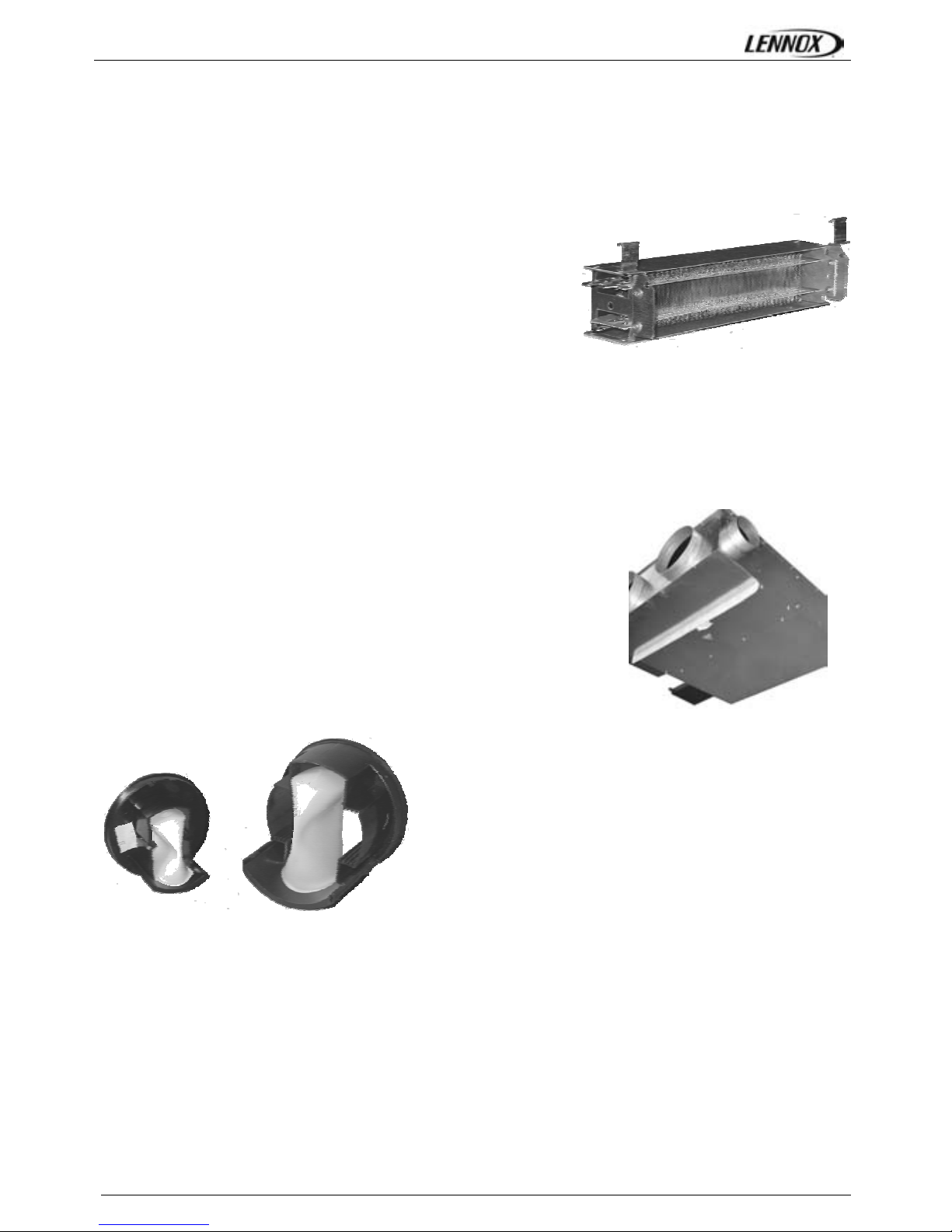
Water coil
The right position of the coil provides a maximum heat exchanger surface for a minimum of space, thus
giving to ARIA range a very interesting ration height/performance.
Available for 2 pipe or 4 pipe applications, the finned block is common offering an increased heat exchanger
surface area.
The aluminium fins are mechanically bonded to 3/8‘’ diameter copper tubes. The inlet and outlet connections
are each provided with a 1/2‘’ G internal diameter threaded nut to facilitate the connection of the flat seal
valve connection. The purge screws are accessible from the outside and opened with a tool.
Following configurations avec available:
• 2 pipes/Change over and 2 pipes/electric heater or
• 4 pipes
2 T 4 T
Size 10
2 R or 3 R
2 R + 1
3 R + 1
Size 20 – 30 – 40
4 R 4 R + 1
Condensate drain tray
The condensate drain tray in aluminium is cast solid and common to the
coil and the valves outside the unit, thus avoiding any risk of possible
escapes. The external part is isolated on its lower part with foam PE
thickness 3 mm, to prevent of any risk of condensation. The tube of
evacuation of external diameter 16 mm makes it possible either to connect
piping directly or to connect a pump with condensate available in option.
ARIA-AGU-1209-E Page 4
Electric heater
The electric heater is of the bare wire resistive type installed in the fan
discharge air stream, assuring optimum coverage and maximum heat
exchange.
Available as standard with a capacity of 500, 800, 1200, 1500 or 3000
Watts, the 230 V/1/50 Hz power supply is provided directly from the
controller or via a relay and a fuse.
The heater is provided with 2 levels of safety:
• A manual reset thermostat, which is reset is by switching off the power, and has a trigger temperature
75°C; whilst this is off a PTC coefficient resistance with a separate supply prevents the automatic reset
of the coil whilst it remains under voltage. Restarting is done by coil supply voltage cut-off. This safety
thermostat protects the unit from over heating due to the absence of airflow.
• A fusible link, rated at temperature152 °C (± 16 °C). Replacement of heater assembly will be required
if this blows, after establishing the cause of the fault.
Filter and access
ARIA is available as standard with a G3 efficiency throwaway filter, 15 mm
thick, which is accessible from the underside of the unit. Fire classification M1.
As an option, ARIA unit can be provided with a G4 filter, 20 mm thick, with
access from the underside of the unit.
Fresh air suppy
ARIA units can be provided with a fresh air connection
spigot as an option allowing the each space to be supplied
with fresh air as required by regulations.
Each spigot can be fitted with a constant volume fresh air
controller to set the air flow to a predefined value. The air
volume is precisely controlled for variations in the system
duct pressure between 50 and 200 Pa.
The fresh air connection is located before the fan and heat
exchanger coil. The external diameter of the connection
spigot is either 99 mm or 124 mm depending upon the
type of controller insta (8.3 or 44.4 l/sec.).
The available controllers are :
Diameter 99 mm : 8.3 to 25 L/sec (30 to 90 m
3
/h – 10% / + 20%)
Diameter 124 mm: 20.8 to 44.4 L/sec (60 to 160 m
3
/h –10%/+ 20%)
The airflow of the 124 mm diameter fresh air controller can be easily modified on site by repositioning the
baffles inside the controller ; an instruction label for this procedure is located on the unit close to the spigot.

ARIA-AGU-1209-E Page 5
Characteristics
Physical and electrical data
ARIA Size 10 Size 20 Size 30 Size 40
Nominal air flow L/sec 139 130 222 228
Available static pressure Pa 50 50 50 50
Total cooling capacity (1) kW 1,94 3,11 4,77 5,68
Sensible cooling capacity (1) kW 1,64 2,4 3,74 4,26
Heating capacity (2) kW 2,36 3,52 5,44 6,16
Electrical supply Single phase – 50 Hz – 230V +/- 10%
Fan
Forward action
simple wheel
Forward action
double wheel
Forward action
double wheel
Forward action
double wheel
Air flow at maximum speed L/sec 160 155 340 345
Available static pressure Pa 80 65 75 80
Fan number 1 1 2 2
Motor
Asynchronus type 230V-1-50
2 poles with internal overload protection, permanent capacitor
Winding insulation class B, varnish class F, IP20
Maximum absorbed power W 197 196 403 407
Nominal current A 0,90 0,90 1,85 1,90
Starting current A 1,1 1,1 2,2 2,3
Water coil
3/8 " copper tubes – Aluminium fins 2 rows / 1 pipe 4 rows / 2 pipes 4 rows / 3 pipes 4 rows / 4 pipes
Water content L 0,5 0,94 1,6 2,25
Operating pressure kPa 16 16 16 16
Test pressure kPa 24 24 24 24
Electric heater
Electrical supply "UDH" bare wire resistive type, single phase – 50 Hz – 230 V +/- 10%
Protections
Manual reset thermostat (reset by switching off the power)
Trigger temperature 75°C thermo fusible link; breaks at 152 °C
500 500 500 500
800 800 800 800
1200 1200 1200 1200
1200 1500 1500 1500
1500 2 x 800 2 x 800
Power (+5% / -10%) not including fan W
1500 2 x 1500 2 x 1500
Minimum air flow L/sec 92 92 92 / fan 92 / fan
Air filter
95% gravimetric efficiency (G3 following EN 779) throwaway type
M1 fire rating, metal wire frame
Dimensions mm 415 x 225 x 10 415 x 225 x 10 715 x 225 x 10 1015 x 225 x 10
Weight and dimensions
Length x width x height (3) mm 886 x 428 x 233 886 x 428 x 233 886 x 728 x 233 886 x 1028 x 233
Weight Kg 16 16 28 35
(1) : Based on water entering temperature of 7 °C and a water temperature difference of 5 °C at nominal conditions, air at 27 °C dry
bulb, 50 % relative humidity
(2) : Based on water entering temperature of 50°C and a water temperature difference of 10° at nominal conditions, air at 20°C
(3) : Dimensions refer to a unit with return and supply spigot, without any condensate drain tray.
ARIA-AGU-1209-E Page 6
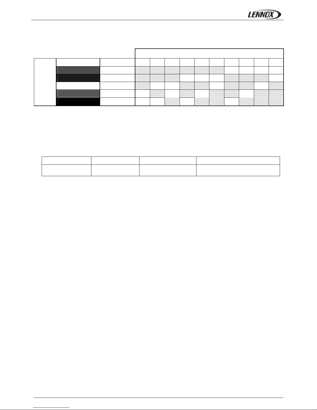
Codification
CODIFICATION
Colour Speed A B C D E F G H I J
RED
1 1 1 1 1 1 1
BLUE
2 2 2 2 2 2 2
WHITE
3 3 3 3 3 3 3
BROWN
4 4 4 4 4 4 4
Motor fan wiring
BLACK
5 5 5 5 5 5 5
NOTA : spigot configuration is defined when viewing ARIA unit looking in the direction of the air flow inside
the unit
Example :
ARIA 20 4R 1R SX
ARIA size 20
4 pipes
4 row heating coil 1 row cooling coil SX hydraulic connection (left side)
ARIA-AGU-1209-E Page 7
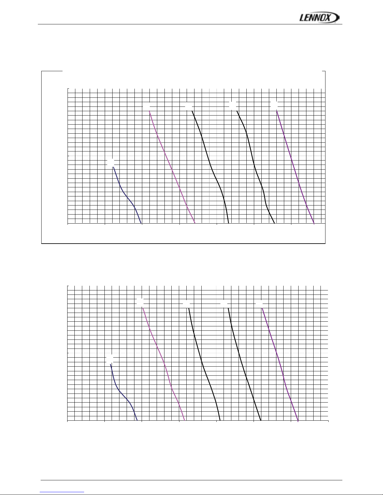
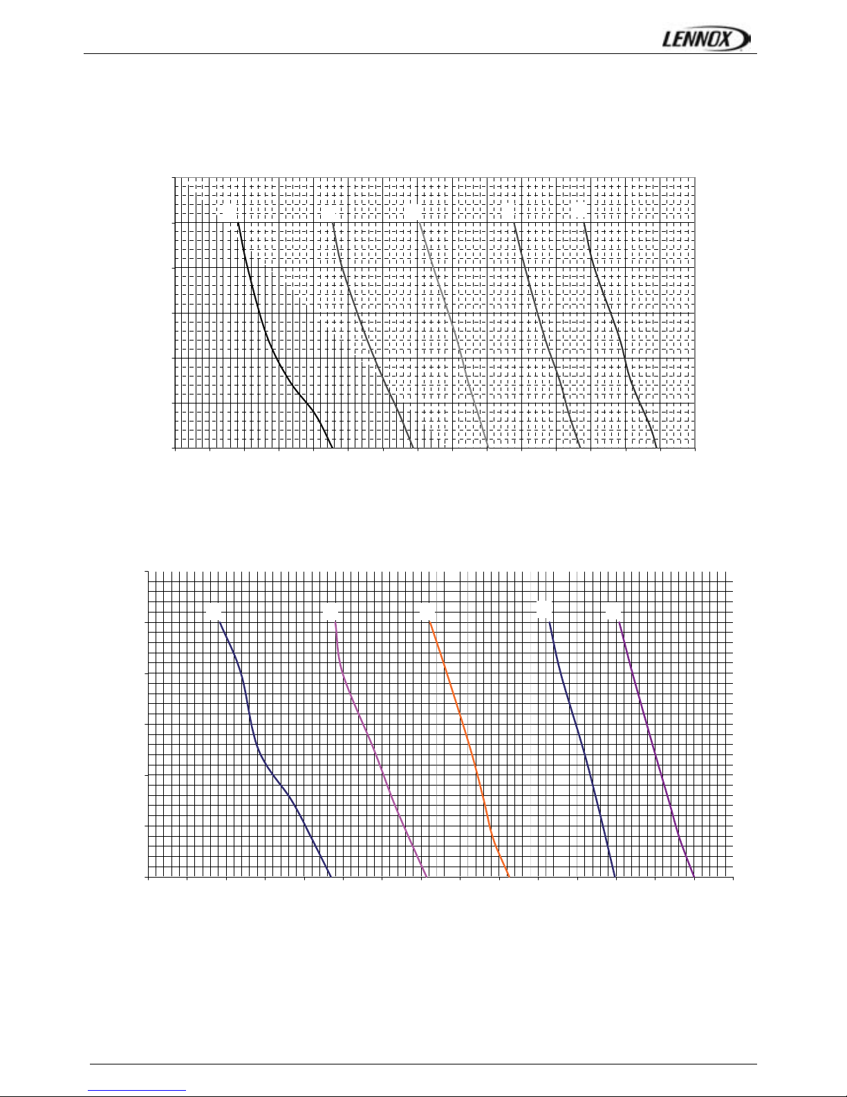
Air flow
ARIA – Size 10
ARIA– Size 20
Caractéristiques Aérauliques ARIA 20
V1
V2
V3
V4
V5
0
20
40
60
80
100
120
0 100 200 300 400 500 600 700
Débit d'air (m3/h)
Pression Dispo (Pa)
Caractéristiques Aérauliques ARIA 10
V1
V2
V3
V4
V5
0
20
40
60
80
100
120
0 100 200 300 400 500 600
7
Débit d'air (m3/h)
Pression Dispo (Pa)
Available static pressure (Pa)
Airflow (m3/h)
Airflow (m3/h)
Available static pressure (Pa)
ARIA-AGU-1209-E Page 8
ARIA – Size 30
Caractéristique Aéraulique ARIA 30
V1
V2
V3
V4
V5
0
20
40
60
80
100
120
0 100 200 300 400 500 600 700 800 900 1000 1100 1200 1300 1400 1500
Débit d'air (m3/h)
Pression dispo (Pa)
ARIA – Size 40
Caractéristique Aéraulique ARIA 40
V1
V2
V3
V4
V5
0
20
40
60
80
100
120
0 100 200 300 400 500 600 700 800 900 1000 1100 1200 1300 1400 1500
Débit d'air (m3/h)
Pression dispo (Pa)
Available static pressure (Pa)
Availalb e static pressure (Pa)
Airflow (m3/h)
Airflow (m3/h)
ARIA-AGU-1209-E Page 9
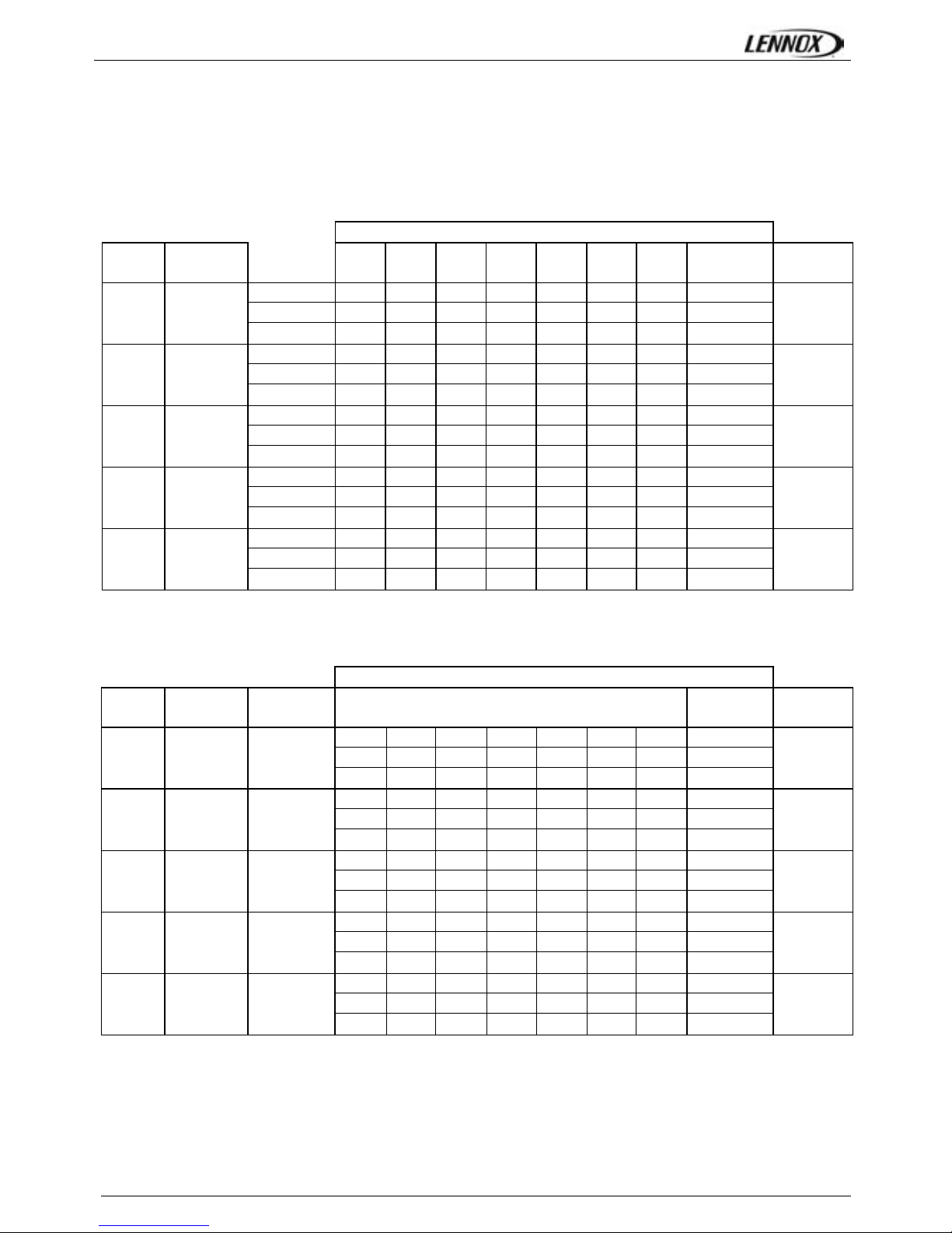
Acoustical performance data
Sound power to an available static pressure of 50 Pa
ARIA – Size 10 & 20
Available static pressure 50 Pa V3.
Spectrum per octave band (Hz)
vitesse
Air flow
(m
3
/h)
125 250 500 1000 2000 4000 8000
global
dBA
Lw Total
(dBA)
Supply 43 45 43 38 31 22 18 44
Return 45 39 45 39 27 20 17 44
V1 180
Radiated 38 32 39 36 33 31 22 41
48
Supply 46 38 46 41 35 25 20 46
Return 48 43 49 38 29 23 18 47
V2 290
Radiated 42 37 40 44 41 38 25 48
51
Supply 49 51 48 43 38 31 21 49
Return 55 48 54 42 37 35 29 52
V3 380
Radiated 43 38 42 46 32 25 30 47
55
Supply 51 53 52 45 42 36 26 52
Return 57 52 56 44 41 40 35 55
V4 470
Radiated 45 44 46 50 38 31 24 51
58
Supply 60 60 53 46 44 42 35 56
Return 67 61 58 46 45 47 45 59
V5 555
Radiated 53 51 47 50 39 37 33 52
61
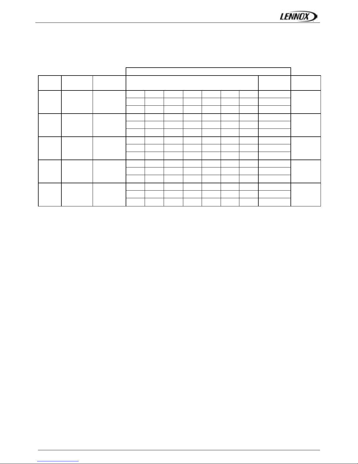
ARIA – Size 30
Available static pressure 50 Pa V3
Spectrum per octave band (Hz)
Vitesse
Air flow
(m3/h)
125 250 500 1000 2000 4000 8000
Lw Global
(dBA)
Lw Total
(dBA)
Supply 49 50 48 40 34 25 21 48
Return 50 44 50 42 30 24 20 49
V1 390
Radiated 43 37 44 41 36 34 24 45
52
Supply 49 41 49 44 38 28 23 49
Return 50 45 50 39 30 30 24 49
V2 600
Radiated 45 39 42 46 42 38 30 49
54
Supply 55 57 55 50 45 38 28 56
Return 57 51 57 44 39 38 31 55
V3 810
Radiated 47 42 46 50 36 29 28 51
59
Supply 57 59 58 52 49 43 33 59
Return 59 55 59 46 44 42 38 57
V4 1030
Radiated 49 48 50 54 42 35 28 55
62
Supply 67 67 59 53 50 49 41 62
Return 70 63 61 48 47 49 47 61
V5 1200
Radiated 58 55 51 54 44 42 37 56
65
ARIA-AGU-1209-E Page 10
ARIA – Size 40
Available static pressure 50 Pa V3
Bande de fréquence (Hz)
Vitesse
Air flow
(m3/h)
125 250 500 1000 2000 4000 8000
Lw Global
(dBA)
Lw Total
(dBA)
Supply 49 50 48 40 34 25 21 48
Return 50 44 50 42 30 24 20 49
V1 390
Radiated 43 37 44 41 36 34 24 45
52
Supply 49 41 49 44 38 28 23 49
Return 50 45 50 39 30 30 24 49
V2 600
Radiated 45 39 42 46 42 38 30 49
54
Supply 55 57 55 50 45 38 28 56
Return 57 51 57 44 39 38 31 55
V3 810
Radiated 47 42 46 50 36 29 28 51
59
Supply 57 59 58 52 49 43 33 59
Return 59 55 59 46 44 42 38 57
V4 1030
Radiated 49 48 50 54 42 35 28 55
62
Supply 67 67 59 53 50 49 41 62
Return 70 63 61 48 47 49 47 61
V5 1200
Radiated 58 55 51 54 44 42 37 56
65
 Loading...