

Page 1
HEARTH PRODUCTS
TM
KITS AND ACCESSORIES
750,238M
REV. NC, 08/2007
INSTALLATION INSTRUCTIONS FOR BLOWER KIT,
MODEL ADAGIO-BLWR (CAT. NO. H6161) FOR USE WITH
ADAGIO™-MN & ADAGIO-MP DIRECT-VENT GAS
FIREPLACE HEATERS
KIT CONTENTS:
1 ea. Blower
1 ea. Instruction Sheet
2 ea. Blower Mounting
Screws
2 ea. Wire Clips
TOOLS / SUPPLIES NEEDED
3/8" Nut Driver
3/4" Wrench
GENERAL INFORMATION
MODEL ADAGIO-BLWR BLOWER KIT
ALL WARNINGS, PRECAUTIONS AND INSTRUCTIONS PROVIDED IN THE
INSTALLATION AND OPERATION MANUAL PROVIDED WITH THE APPLIANCE
APPLY TO THESE INSTRUCTIONS. THOROUGHLY READ AND FOLLOW THE
INSTRUCTIONS PROVIDED WITH THE APPLIANCE BEFORE PROCEEDING TO
THE FOLLOWING INSTRUCTIONS.
INSTALLATION INSTRUCTIONS
Step 1. For your safety, turn off the fireplace and allow it to cool before
proceeding.
Step 2. If the appliance is connected to 120 volt power, disconnect the
power by turning off the circuit breaker.
Step 3. Shut off the gas supply to the fireplace.
IMPORTANT NOTE: This Forced Air Blower Kit can be use on
millivolt models only.
The main power supply must be wired to the J-box/receptacle and wall
switch at the time the fireplace was installed (if not, then this kit cannot
be installed).
IMPORTANT
• All electrical wiring must be performed by licensed
Electricians. Electrical wiring must comply with
the National Electrical Code ANSI/ NFPA 70 latest edition, in Canada, the current CSA C22-1
Canadian Electrical Code.
• Main power must be off when connecting to main
electrical power supply or performing service .
• The Ground Lead must be connected to the green
screw (located on the junction box). Failure to do
this could result in an electrical short or shock
injury.
• The appliance must be electrically grounded in
accordance with local codes or, in the absence of
local codes, the national electrical code, ANSI/
NFPA 70-(latest edition), in Canada, the current
CSA C22-1 Canadian Electrical Code.
• Leather gloves should be worn during installation
to prevent injury or cuts to the hands!
NOTE: DIAGRAMS & ILLUSTRATIONS ARE NOT TO SCALE.
Step 4. Remove the façade if installed.
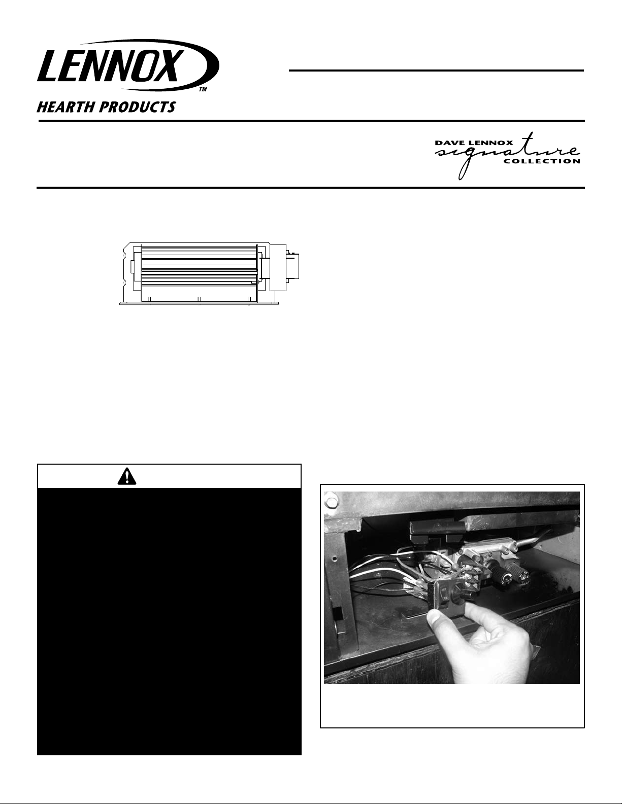
Step 5. Remove the existing on/off switch (for burner) and bracket in the
control compartment per the instructions in Figure 1. Do not
remove the On/Off switch or Piezo from the bracket.
Step 6. Remove Gas Line to allow for easier access to blower mounting
location. See Figure 3
Figure 1 - Remove Switch and Piezo Bracket as shown by pulling
the assembly toward you (no tools required)
1
Page 2
Step 7.
OPTIONAL WALL-MOUNT SWITCH
OR WALL-MOUNT RHEOSTAT
Junction Box
Tab Intact
Tab
Broken
Plug blower
into this
receptacle
n e e r G - d n u o
r
G
Wall-mounted
ON/ OFF Switch or
Variable Speed Control
Switch (rheostat) *.
Blower
Ground
e
t i h W
-
l a r t u e N
120 VAC - Black
Green
Ground
Screw
White
Green
Neutral
Side of
Receptacle
Hot
Side of
Receptacle
Red
Black
J-BOX WIRING FOR
WALL SWITCH
BLOWER CONTROL
Slide the blower assembly in through the left side of the control
compartment, see Figure 3. The blower power cord should be
routed to the J-Box/Receptacle and plugged in. Route power
cord and fasten Wire Clips as shown on Figure 3.
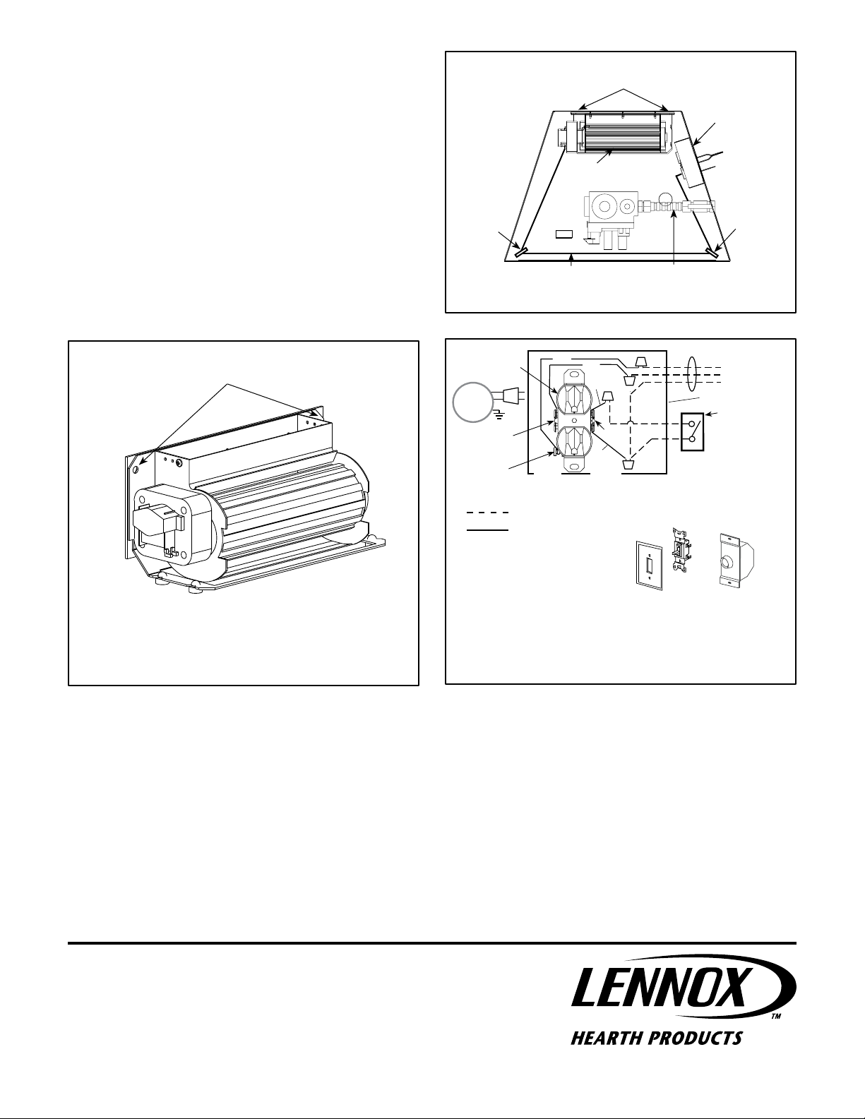
Step 8. Using the 1/4" hex screws provided, mount the blower using
the two screw holes. See Figure 2 and 3
Step 9. Reinstall Piezo Bracket that was removed in Step 5.
Mounting Screw Locations
Junction Box
Blower
Step10. Reinstall gas line that was removed in Step 6.
Step 11. Restore the electrical power to the appliance. Turn on blower
with the optional wall-mounted switch to test for proper operation.
see Figure 4.
Step 12. Turn on gas supply to fireplace.
Mounting Screw Locations
Figure 2 - Mounting Screw Locations
Wire Clip
Power Cord
Figure 3 - Top View of Cabinet Bottom
Factory Wired
Note: If any of the original wire
as supplied must be replaced, it
must be replaced with type AWM
105 degree C - 14 gage wire.
On/Off Switch
Provides on/off control
of constant velocity forced air circulation.
Figure 4 - Blower Wiring Diagram
Gas Line
Optional Wall Switches *Field Wired
Wire Clip
Rheostat
Provides on/off control
and variable speed
control of the velocity
of forced air circulation.
2
Printed in U.S.A. © 2007 by Lennox Hearth Products
P/N 750,238M REV. NC 08/2007
NOTE: DIAGRAMS & ILLUSTRATIONS ARE NOT TO SCALE.
1110 West Taft Avenue • Orange, CA 92865
 Loading...