

Page 1

APPLICATION
GUIDE
Polyvalent air cooled heat pump
AQUA
4
AAH
50 330 kW
AQUA4-AGU-1405-E
lennoxemeia.com
Page 2

Page 3

1 Table of Contents
1 TABLE OF CONTENTS ........................................................................................................ 1
2 MODEL NUMBER DESCRIPTION ......................................................................................... 2
3 KEY CUSTOMER BENEFITS ................................................................................................ 3
3.1 THE AQUA4 P ................................................................................................................ 3
3.2 THE AQUA4 M ................................................................................................................ 3
3.3 BENEFITS ...................................................................................................................... 3
4 FEATURES AND BENEFITS ................................................................................................ 4
4.1 STANDARD EQUIPMENT ..................................................................................................... 4
4.2 INNOVATIONS PRODUCT: SOLVING THE DEF ROSTING PROBLEM.................................................. 5
4.3 STRUCTURE ................................................................................................................... 5
4.4 REFRIGERANT CIRCUIT...................................................................................................... 5
4.5 COMPRESSORS ............................................................................................................... 5
4.6 BRAZED PLATE HEAT EXCHANGERS ..................................................................................... 5
4.7 CONTROL BOX ................................................................................................................ 5
4.8 CONTROL AND COMMUNICATION ......................................................................................... 6
5 OPTIONS AND ACCE SSORIES ............................................................................................ 7
6 APPLICATION ................................................................................................................... 10
7 OPERATING COMBINATION DEPENDING ON THE THERMAL LOAD: ................................. 14
8 OPERATING LIMITS .......................................................................................................... 16
9 TECHNICAL DATA - PERFORMANCES .............................................................................. 17
10 OVERVIEW DIAGRAMS ..................................................................................................... 42
11 INSTALLATION ................................................................................................................. 45
11.1 FOR FURTHER INFORMATION SEE THE USER AND MAINTENANCE MANUAL. .................................. 45
11.2 PRE LIMINARY PROCEDURES ............................................................................................. 45
11.3 WATER CONNECTIONS .................................................................................................... 46
11.4 EL ECTRICAL CONNECTIONS ............................................................................................. 48
11.5 EL ECTRIC CONNECTIONS OF THE CIRCULATION PUMP ............................................................ 48
11.6 USE OF GLYCOL SOLUTIONS ............................................................................................ 48
11.7 OPERATING AND STORAGE LIMITS ..................................................................................... 48
La déclaration de conformité accompagne chaque unité
AQUA4–AGU-1405-E - 1 -
Déclaration de conformité
Page 4

1 = 2 compressors / 2 circuits
4 = 4 compressors / 2 circuits
M= 2 pipes
P= 4 pipes
S= standard noise level
L= Low noise level
2 MODEL NUMBER DESCRIPTION
The AQUA4 units are identi fied by the followi ng codes: Example AAH081MS
A AQUA
A Air Cooled
H Heat Pump
08 Nominal Cooling c apacity x10 [kW] (ex.: 08 = 80 kW)
1
M
S
4
AQUA4–AGU-1405-E - 2 -
Page 5

Cooling
Heating
Circuit 1
Circuit 2
Cooling + Heating
Circuit 1
Circuit 2
Cooling
Circuit 1
Heating
Hot water
Cooling + Hot
water (DHW)
Heating + Hot
water (DHW)
Circuit 1
Circuit 2
Circuit 2
Circuit 2
Circuit 1
Circuit 1
3 KEY CUSTOMER BENEFITS
Nominal cooling capacity @ 12/7°C and 35°C air ambient: 50 to 330kW
Nominal heating capacity @ 40/45°C and 7°C air ambient: 50 to 340kW
3.1 The AQUA4 P: unique concept for thermal comfort with less energy consumption.
The polyvalent heat pump AQUA4 P units are designed to meet the requirements of simultaneous and independent cooling and
heating for air c onditioning in the m ost efficient way. The AQUA
building and are more commonly called 4 pi pe system.
4
P units provide a hot water circuit and a cold water circuit to the entire
3.2 The AQUA4 M: hot water all the year at a lower cost.
The polyvalent heat pump AQUA4 M units are designed to m eet the requirement s of cooling and / or heati ng in the most effic ient way.
The units have the abil ity to provide hot water simultaneously or independently of cooling and heating needs. The AQUA
generally call ed 2 pipe units because two hydraulic pipes are connected to the t erminal building, the other two hydraul ic pipes are
generally dedicated to hot sanitary water.
production (DHW)
4
M units are
3.3 Benefits :
Conserving and optimizing energy consumption
- High energy ratio at part load and full load (EER/COP/ESEER)
- Simultaneous or independent demands for heating and cooling
- Constantly balanced heating and cooling needs to obtain ma ximum Total Efficiency Ratio : TER*
- 100% heat recovery at any conditions
- Advanced programmable pCO1 with a local control inter face PGD1
Secure operatin g m ap as standard
- Winter cooling operation down to -15°C ambient.
- Heating operation down to -10°C ambient wi th 45°C outlet wate r temperature
- Heat recovery or production of hot water temperature fr om 25°C to 55°C
- High ambient operating up to 45°C
Quieter unit
- -8 dB(A) noise level reduction vs traditional heat pump in standard
- Jump to -12dB(A) noise level reduction with low noise version
- Innovative hybri d structure of fan blades
- Unique sound proof cabinet enclosing all components to r educe radiated sound levels
Defrost without impacting comfor t
- Hydrophilic tr eatment on coil
- Dynamic control on defrost
- Circuits defrost completely independently
- Integrated water tank up to 765 litres
(*) TER : Total Efficiency Rat io is the total energy ef ficiency of the unit s when there is a produc tion of chilled water and hot water
simultaneously. Cold water and hot wat er are valuated to the total power consumpt ion of the unit: TER = (cooling capacity + recovered
heating capacity) / total power consum ption. Energy ratio TER of polyvalent heat pumps are si gnificantly higher than the standard EER
and COP demonstr ating considerable energy savings during inter-season per iods (version P) or dom estic hot water production (M
version).
AQUA4–AGU-1405-E - 3 -
Page 6

4 FEATURES AND BENEFITS
4.1 Standard equipment
• R410A refrigerant
• Two ref rigerant circuits
• ISO 9001 certification.
• Compli ant with CE norms (P ED directive 97'23)
• Galvanized steel base fr am e powder coated RAL70 31
• Galvanized steel cabinet powder coated panels RAL9002
• Main di sconnect switc h w ith lock
• Ventilated electrical control panel
• High efficiency scr oll compressors mounted in a closed technical box
• High efficiency braze plate heat exchangers insulated
• Thermostatic expansion valves
• Axial fans with innovative hybrid structure of blades
• Speed var iation on ventilation, modulatio n phase cut out
• Copper tubes and aluminum f ins coils with hydrophilic coating
• Grouved water connections (Victaulic type)
• Paddl e w ater flow switch
• Low nois e version: Low speed on fan with sound insulation of the entire technical box.
• Advanced control programm able pCO1 with local interface
• Other s components :
• Note : the low noise versions have a fully soundproofed technica l casing and include l ow fan speed
o PGD1 unit display
o Scheduling
o Defrost system independent of each c ircuit
o Water set-point offset based on outdoor air temperature.
o Operating time equalisation of the compressors and pumps
o Master/slave or cascade control .
o Filter driers m olecular sieve
o Liquid moisture i ndicator
o Tanks and liquid separators with mar king complies wit h EE C D irective 97/23 PED
o High and low press ure switch
o Solenoid valves
o Schrader valves
AQUA4–AGU-1405-E - 4 -
Page 7

4.2 Innovations Product: solving the defrosting problems
Thanks to two indepe ndent thermodynamic circuits, the AQUA4 unit is essential on the market as an exclusive solution t hat can
continue to produce hot water for heating or sanitary uses while simultaneously performing a defrosting cycle.
During winter, especially in the -3°C - +3°C range, the high rel ative air humidity condenses water around the coil fins. Since the coil is at
a lower temperature than the air, any water that touches it solidifies and blocks the exchange of heat nec essary for the system to
correctly operat e. The defrost cycle is a temporary reversal of the thermodynamic cycle operat ing the appliance in cooling mode and is
used to melt ice present between the fins. This phase is of course problematic but AQUA
following innovat ions:
Hydrophilic coils are installed. These reduce the size of the wate r drops along with ice blockage between fins. Due to the
lower surface tension, water tends to slide away due to gravity, thus preventing the formation of frost at low temperatures.
Software management minim ises defrosting cycle time, allowing cycle operation onl y w hen necessary. Fans operate at
maximum power only wh en the ice is no longer attached to the fins. It can then be pushed out from the coil.
The two thermal circuits in AQUA
machine operating, with basically no t hermal discomfort for the user.
4
M and AQUA4 P are completely independent. Whil e one defrosts, the other keeps the
4
system can mitigate this problem thr ough the
4.3 Structure
All AQUA4 series units have a load bearing base and paneling in galvanized sheet metal paint ed with polyester pow ders and
polymerized in the oven at 180°C. The unit is attractivel y designed and when all door s are closed all the components are inac cessible.
This, along with t he extensive use of s oundproofing material inside the compartment and around the compressors (available for the
low-noise versi on), reduces sound to e xceptionally low level s. The water/cool er connections are on the back (when looki ng at the
electric panel) reducing the space required for installation. The unit is fully accessible as all the panels can be removed (except the one
with the water connections). Routine maintenance however only requires access from the front.
4.4 Refrigerant circuit.
The cooling circuit is manufactured i n our factory, with top brand component s by operatives trained, according t o D irective 97/23, on al l
the brazing operati ons.
4.5 Compressors
Only top-quality Scroll compressor s are used on AQUA4 units. Scroll compressors are the bes t solution in terms of reliability and
efficiency. T hey also provide the lowest amount of sound emissions. Process optimisation, along with a carefull y selected intrinsic
volumetric com pression ratio (RVI), clearly improves the isentropic compression performance and reduces energ y losses. The use of a
scroll compressor allows low visc osity oils to be used. Thi s, in comparison t o higher viscosity oils, reduces ther mal resistance at the
evaporator. It also increases the evap oration temperature by over 1.5°C (EER increases by more than 5.5%) compared to other
solutions.
Compressor motors are protected against overheating, overloads and high delivery gas tempera tures. They are mounted on antivibration rubber , complete with oil charge and inserted in a soundproof compartment with sound-absorbing material . They are also
equipped with an automatic crankcase heater that, when the compressor st ops, prevents the oil from being diluted by the r efrigerant.
4.6 Brazed plate heat exchangers
Only brazed plate heat exchangers ar e used, made of austenit ic stainless steel AISI 316, with AISI 316L connections. These feature a
reduced carbon content that favours brazing operations. The brazed plate heat exchanger represents state-of-the-art technology in
terms of thermal exchange efficiency and allows a strong reduction of the refrigerant load compared to standard solutions. The high
degree of turbulence generated by internal plate corrugat ion, along with plat e smoothness, m akes it difficult for dirt to accumulate or for
limescale to build up on the condenser circuit. These heat exchangers also make it possible to use R410A fl uid which, thanks to the
high-level of its thermal conductivity in its liquid phase and to its azeotropic behaviour, enhances thermal exchange during evaporation.
The performances are improved over other methane-deriv ative fluids of t he H FC group.
- NOTE: due to thermal ins ulation the data plat e (in compliance wi th PED CE 97/23) is not legible. However, the serial number of the
heat exchanger and the declaration of conformity are both recorded during production and are an i ntegral part of the company
archive.
4.7 Control box
The electric panel is built and wired in accordance with standard EN 60204-1. The electric panel is accessed from the front of the
machine. Before it can be accessed, t he unit must be disconnec ted from the power suppl y using the mains di sconnect switch, which
also functions as a door-lock. All the remote controls are implemented with low voltage 24 V signals, powered by an isolation
transformer inside the electric panel. All the control boards have an air circulation system wi th auxiliary fans. The position of the main
switch makes wir ing operations in the work site easier. This avoids several difficult operations as well as having to twist the power
cords. All the ut ilities are protec ted against surges and short circuits. The circuit breaker set-up can be configure d for any load
AQUA4–AGU-1405-E - 5 -
Page 8

(optional). Ther m al protection, however, is carried out by thermistor chains. These are set in the windings of each elec tric motor and are
controlled by onboard electronics. All units are equipped as standard with a phase sequence relay w hich inhibits compressor operation
if the phase sequence is not carried out: only one direction of rotation is possible for scroll compr essors, as well as for the screw and
Rotary compressors. The unit is s uitable for outdoor i nstallation.
4.8 Control and communication
The AQUA4 series units come complete with Advanced Carel, pCO series microprocessor control, in addition to the f unctions descri bed
below, it is possible to customise the software to meet all system requests. T hese include cascade management of the units with
‘’step-control’’ or ‘’cascade’’ logic. The microprocessor on board the unit controls the various operating parameters with an electric
panel keypad:
• Compressor connecti on/disconnection to maintain the set -point of the chiller inlet water T
• Alarm management
• Alarm signals
• Dis play of operating parameters
• Evapor ator anti-freeze pr otection
• Contr ol of maximum number of compressor starts
• RS232, RS485 serial output control (optional)
• Inc orrect phase sequence ( not viewed on display, prevents the compressor from st arting)
Concerning interface communication, Modbus ®, BacNE T ® (RS485 or TCP / IP) or LonWorks ® (optional) interface communication
cards are provided for connection to BM S systems as an option.
o High / low pressure
o Anti-freeze
o Flow switch
o Pump alarm
AQUA4–AGU-1405-E - 6 -
Page 9

Options
Features and Benef its
Power supply
5 Options and Accessories
Supply 400V / 3 ph / 50Hz with 230V transform er and fuses Supply without neutr al with a 230V transformer and fuses.
Supply 400V / 3 ph + Neutr al / 50Hz with circuit breakers
Supply 400V / 3 ph / 50Hz with 230V transform er and circuit
breakers
Hydraulic module of both water circuits
Hydraulic module with low-pressure single pump
Hydraulic module with high-pressure single pump
Hydraulic module with low-pressure twin pumps (parall el
operating)
Hydraulic module with high-pressure twin pumps (parallel
operating)
Hydraulic module with low-pressure twin pumps (normal/backup
switching)
Hydraulic module with high-pressure twin pumps (normal/backup
switching)
Supply with neutral, the fuses have been replaced by
thermomagnetic circuit breakers.
Supply without neutral but with a 230V transformer and
thermomagnetic circuit breakers.
Single pump providing low static pressure with expansion vessel
and safety valve
Single pump providing high static pressure with expansion vessel
and safety valve
Dual pumps providing low static pres sure with expansion ves sel
and safety valve. The two pumps operating simultaneously in
parallel.
Dual pumps providing high static pressure with expansion v essel
and safety valve. The two pumps operating simultaneously in
parallel.
Double pumps providing low static pressure with expansion vessel
and safety valve. One pump operates and the second pump is in
backup with balancing operation time.
Double pumps providing high static pressure with expansi on
vessel and safety valve. One pump operates and the second pump
is in backup with bal ancing operation time.
Water tank
Water tank on col d use (4 pipes) / reversible use (2 pipes)
Water tank on hot us e (4 pipes or 2 pipes)
Water tank volume :
- 200 litres for si zes 041-051
- 220 litres for sizes 061-071-081
- 340 litres for si zes 094-104
- 600 litres for sizes 124-144-164-194-214-244
- 765 litres for sizes 274-294-324
AQUA4–AGU-1405-E - 7 -
Page 10

Options
Features and Benef its
Antifreeze protection
Antifreeze protection on exchangers and pipes
Antifreeze protection on exchanger s, pipes, pump(s ) and
expansion vessel
Antifreeze protection on exchanger s, pipes, pump(s ), expansion
vessel and water tank
Condensing control
Electronically controlled modul ating fan speed with EC motors
Remote Control
Remote display (s upplied loose)
Control interf ace
Electrical trace heating and reinforced insulation on the both braze
plate heat exchangers and pipes.
Electrical trace heating and reinforced insulation on the brazed
plate heat exchangers, pipess, pump(s) and the expansion vessel.
Electrical trace heating and reinforced insulation on the both
brazed plate heat exchangers, pipes, pump(s), expansion ves sel
and the water tank.
PGD1 user interf ace allows performanc e of all operations of the
program, displaying the status of the unit and changing settings. It
can be located up to a maximum of 50 meters from the unit with a
standard telephone cable and up to a maximum of 200 meters
from the unit with a shielded cable.
Modbus communic ation interface RS485
LonWorks® communication interface FTT10
pCOweb - Modbus/BACnet/SNMP communication interfac e
TCP/IP
Anti-vibration i solation
Rubber anti-vibr ation mounts (supplied loose)
Spring anti-vibration mounts (s upplied loose)
Communication card using ModBus or Carel protocol RS485.
Communication int erface with a buildi ng management system.
Communication card using LonWorks® FTT10. Communication
interface wit h a building management system.
Communication card using Modbus/BACnet®/SNMP TCP/IP.
Communication int erface with a buildi ng management system.
4 or 8 rubber anti-vibration isolator s are supplied depending on the
type of unit. They wil l be inserted between the floor and the unit to
prevent vibration.
4 or 8 spring anti-vibration isolators are supplied depending on the
type of unit. They wil l be inserted between the floor and the unit to
prevent vibration.
AQUA4–AGU-1405-E - 8 -
Page 11

Accessories
Features and Benef its
Accessories
Power factor Cor rection
Capacitors f itted into unit. Cos phi correction up to 0.95 t o reduce
current and energy consumption.
Electronic soft starter included in the contr ol panel. Reduces t he
peak starting current by up to 40%. T hey also partici pate in the
Soft starter
installation design optimization of the electric al cables and reduce
the mechanical stresses on the compr essors. In addition, they
assure that the unit will not start operating in case of overvoltage,
under voltage, phase reversal fault or phase failure.
Victaulic coupl ing parts (x4) Four Victaulic couplings (suppli ed loose)
Set point and temper ature offset and display. Allows to offset
External temperatur e sensor for set point offset
chilled water set point temperature based on either outside air,
chilled water return or zone temperature.
Pressure gauges LP / H P Reading low and high pressures with gauges.
Filter dryer maintenance kit
This kit includes one solenoid valve and ball valve per circuit for
maintenance of dryer filters.
Two lifting tubes are supplied to be inserted in the round holes on
the base frame identified by sticker s.
- 2 x tubes Ø1"1/2 (38mm), thickness =2,9m m , Length=1370mm
Lifting tubes ( x2)
on size 041 to 104
- 2 x tubes Ø1"1/2 (38mm), thickness =2,9m m , Length=1840mm
on size 124 to 324
+ 4 x bolt M16 Inox (as stops at the end of the tube)
Coils protecti on guards
Water Y filters (x2) (supply loose)
The condenser coi l protection grills prevent light damage to the coil
when shipping, installation and oper ation.
This option incl udes two Y water filters supplied loose:
- 2'' GAS (screwed) on size 041 to 104
- 3'' GAS (screwed) on size 124 to 194
- 4'' Flange on size 214 t o 324
Note that the connec tions of the units are victaulic.
We can supply the adapt ers : Victaulic / Gas or Victaulic / Flange
via a Non Standard Request
AQUA4–AGU-1405-E - 9 -
Page 12

Cooling
Circuit 1
Heating
Hot water
Cooling + Hot
water (DHW)
Heating + Hot
water (DHW)
Circuit 1
Circuit 2
Circuit 2
Circuit 2
Circuit 1
Circuit 1
A B D
C
B+D
6 Application
The AQUA4 units allow creating installations with 2 or 4 pipes. The designation 2 or 4 pipe refers to the system of the water distribution
for each building system.
A 2 pipe system comprises a single supply and a single hydraulic line back to the unit. The terminal units of a system to 2 pi pes are
characterized by a single exchanger having the coil function of heating or cool ing depending on the op erating mode.
The 4 pipe configur ation includes hot water supply (wi th the corresponding return lines) and col d w ater (with the corresponding return
lines) simultaneously.
Operating modes available for AQUA
- Circuit 1, reversible system: produc tion of chilled wat er for cooling or hot water for heating.
- Circuit 2, hot water per production or total heat recovery for hot water sanitary type for example.
4
M units can be mounted on a 2-pipe system:
production (DHW)
AQUA4–AGU-1405-E - 10 -
Page 13

Example of 2 pipe installation for H otel and Hospital:
AQUA4–AGU-1405-E - 11 -
Page 14

Cooling
Heating
Circuit 1
Circuit 2
Cooling + Heating
Circuit 1
Circuit 2
A D
C
Operating modes available for AQUA4 P units will all ow provision of hot and cold water simultaneously.
- Circuit 1: Production of cold water for cooling
- Circuit 2: Hot water production or total heat recover y for heating or preheating hot water for example.
AQUA4–AGU-1405-E - 12 -
Page 15

Example of 4 pipe ins tallation for office or residential buildings:
Below is shown an example of an inertial tank with double cycle inversion (on demand) for winter and sum mer air conditioning, in
combination with a 2-pipe heating system. The double cycle inversion valve ( automatically c ontrolled by onboard microprocessor)
provides the best performance as i t favours tank strati fication in both summer and winter modes.
AQUA4–AGU-1405-E - 13 -
Page 16

o 100% Cooling
o 25% Cooling
o 100% Heating
o 25% Heating
o 100% Cooling + 50% to 100% DHW
o 25% Cooling + 25% to 75% DHW
o 100% DHW
o 25% DHW
o 100% DHW
o 25% DHW
o
7 Operating combination depending on the thermal load:
The following tables show the possible operating regimes of the AQUA4 units at partial loads. The units ar e equipped with two
thermodynamic circuits and two or four compressors that combine their operations t o m eet the changing demands of the heating
system. For example, in heating mode, the units AQUA
domestic hot wat er.
- AQUA M (2 pipe) units : 2 compressors / 2 thermodynamic circuits :
Summer: Cooling mode Winter : Heating m ode
o 100% Cooling
o 50% Cooling
4
M (2 pipe) are able to shar e their heating capac ity with 50% heating and 50%
o 100% Heating
o 50% Heating
o 100% Cooling + 50% to 100% DHW
o 50% Cooling + 50% to 100% DHW
o 100% DHW
o 50% DHW
- AQUA M (2 pipe) units : 4 compressors / 2 thermodynamic circuits :
Summer: Cooling mode Winter : Heating m ode
o 75% Cooling
o 50% Cooling
o 75% Cooling + 25% to 75% DHW
o 50% Cooling + 25% to 100% DHW
o 75% DHW
o 50% DHW
- AQUA P (2 pipe) units : 2 compressors / 2 thermodynamic circuits :
All the year : Summer to winter
o 50% Heating + 50% DHW
o 100% DHW
o 50% DHW
o 75% Heating
o 50% Heating
o 25% Heating + 25% to 50% DHW
o 50% Heating + 25% to 50% DHW
o 75% DHW
o 50% DHW
AQUA4–AGU-1405-E - 14 -
o 100% Cooling
o 50% Cooling
o 100% Cooling + 50% to 100% Heating
o 50% Cooling + 50% to 100% Heating
o 100% Heating
50% Heating
Page 17

- AQUA P (2 pipe) units: 4 compressors / 2 thermodynamic circuits :
All the year : Summer to winter
o 100% Cooling
o 75% Cooling
o 50% Cooling
o 25% Cooling
o 100% Cooling + 50% to 100% Heating
o 75% Cooling + 25% to 75% Heating
o 50% Cooling + 25% to 100% Heating
o 25% Cooling + 25% to 75% Heating
o 100% Heating
o 75% Heating
o 50% Heating
o 25% Heating
AQUA4–AGU-1405-E - 15 -
Page 18
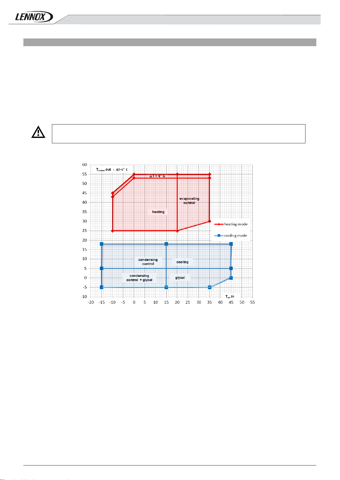
Outlet water temperature ∆T=5°C
Air ambient temperature
The use of units AQUA4 series is possi ble within the operat ing limits shown in this document under penalty of
8 Operating Limits
This paragraph lists the operating l imits of the AQUA
and air temperature.
The nominal flow r ate refers to a temperature differenti al of 5° C between inlet and outlet water, in relation to the cooling capacity
provided at nominal water temperatur es. The maximum allowa ble flow rate is associated with a temperature differenti al of 3 °C. Higher
flow rates cause unacceptable drops in pressure. The minimum allowable flow rate is achieved with a temperature differential of 8 °C.
Lower flow rates m ay result in low evaporation temperatures, which could t rigger the safety devices and stop the unit. T hey m ay also
cause an incorrect distribution or heat transfer in a non-t urbulent or not ful ly turbulent flow. For temperature diff erentials outside these
limits contact the company's technical department for advise.
The AQUA
4
units are designed to exchange heat wit h water in countercurrent to the plate heat exchangers on the full recovery circuit.
In cooling mode they are also in countercurrent on the heat exchanger (utilit y circuit). The AQUA
utility circuit. In this case, select the supplied “water circuit cycle inversion valve” accessory to achieve countercurrent.
discharge of the guarantee provided for in the terms and conditions of s ale.
Operating range of the AQUA
4
units in cooling mode and with heat pump i n countercurrent m ode:
4
M and AQUA4 P heat pumps, in rel ation to utility circuit water outlet temperature
4
M unit can also gener ate heat on the
AQUA4–AGU-1405-E - 16 -
Page 19

BOX
F1+
F1+
F2+
F2+
F2+
F3+
F3+
F4
F4
F4
F4
F5
F5
F6
F6
F6
Nb of circuit
2
2 2 2 2 2 2 2 2 2 2 2 2 2 2 2
Outlet water temperature of hot circuit- ∆T=5°C
Température de sor tie d’eau du circuit froid - ∆T=5°C
Outlet water temperature ∆T=5°C
Air ambient temperature
Outlet water temperature of cold circuit - ∆T=5°C
Operating range of the AQUA4 units in cooling mode and with heat pump i n concurrent mode:
Operating range of the AQUA
The diagrams were pl otted with a temperat ure differential at the plate exchang ers (water circuit) of 5°C
4
units in full recovery mode:
9 Technical Data - Performance
Performance was calculated in counter current to the plate heat exchangers . Countercurrent can only be achieved for the LCP M unit in
the utility circuit heat pump mode, by s electing the “Water circuit 4-way cycle inversion valve” or by modifying the system. If this can't be
achieved, then calculate performances in the concur rent mode, referring to manual or selec tion software performances (all expressed in
countercurrent), at a water temperature that is 3°C lower. For example, perf ormances in countercurrent production of 45/50°C hot water
approximates the concurrent perf ormances of 42/47°C water
Refer to the chapter "Use of glycol sol ution" for the correction factors of performance when using glycol.
AQUA4 041 051 061 071 081 094 104 124 144 164 194 214 244 274 294 324
AQUA4–AGU-1405-E - 17 -
Page 20

Nb of compressor
2
2 2 2
2 4 4 4 4 4 4 4 4 4 4
4
AQUA4–AGU-1405-E - 18 -
Page 21

Unit M (2 pipes) et P (4 pipes) version S
AAH041
AAH051
AAH061
AAH071
AAH081
Cooling at 12/7°C with air ambient at 35°C
ESEER
4.13
4.08
4.24
4.19
4.09
COP
3.24
3.21
3.26
3.21
3.24
Total absorbed pow er
kW
15.1
16.9
19.3
21.7
24.4
Table 1 – General dat a of AQUA4 M and AQUA4 P standard S version from AQUA4041 to AQUA4081 in nominal conditions :
Cooling capacity kW 49.7 54.3 65 71.3 81.4
Total absorbed pow er kW 15.9 18 20.4 23 26.6
EER 3.13 3.02 3.19 3.10 3.06
Water flow l/h 8533 9324 11165 12243 13985
Total pressure drop kPa 27 31 32 38 31
Available pressure head - Pump(s) LP single or normal/backup
switching (opti on)
Available pressure head - Pump(s) HP single or normal/backup
switching (opti on)
Available pressure head - Twin pumps LP parallel operating
(option)
Available pressure head - Twin pumps HP parallel operating
(option)
kPa 155 147 138 126 126
kPa 190 182 198 189 194
kPa 128 121 117 107 112
kPa 178 171 164 154 158
Heating at 40/45°C with air ambient at 7°C
Heating capacity kW 51.9 57.2 67.9 74.4 84.6
Total absorbed pow er kW 16 17.8 20.8 23.2 26.1
Water flow l/h 9022 9945 11794 12930 14701
Total pressure drop kPa 30 36 36 43 35
Available pressure head - Pump(s) LP single or normal/backup
switching (opti on)
Available pressure head - Pump(s) HP single or normal/backup
switching (opti on)
Available pressure head - Twin pumps LP parallel operating
(option)
Available pressure head - Twin pumps HP parallel operating
(option)
kPa 144 134 125 110 111
kPa 179 169 188 177 183
kPa 119 111 107 95 101
kPa 168 159 153 140 145
Cooling 12/7°C and Heating at 40/45°C
Cooling capacity kW 48.9 53.9 63.6 70.3 82.3
Heating capacity kW 63.3 70 81.9 90.9 105.5
TER 7.43 7.33 7.54 7.43 7.70
Water flow of cold circuit l/h 8395 9259 10916 12077 14138
Water flow of hot circuit l/h 10993 12168 14237 15798 18336
Available pressure head - Pump(s) LP single or normal/backup
switching (opti on) - cold circuit
Available pressure head - Pump(s) HP single or normal/backup
switching (opti on) - cold circuit
Available pressure head - Twin pumps LP parallel operating
(option) - cold circuit
Available pressure head - Twin pumps HP parallel operating
(option) - cold circuit
Available pressure head - Pump(s) LP single or normal/backup
switching (opti on) - hot circuit
Available pressure head - Pump(s) HP single or normal/backup
switching (opti on) - hot circuit
Available pressure head - Twin pumps LP parallel operating
(option) - hot ci rcuit
Available pressure head - Twin pumps HP parallel operating
(option) - hot ci rcuit
kPa 157 148 140 128 125
kPa 191 183 200 191 193
kPa 129 122 119 109 111
kPa 179 171 167 156 156
kPa 127 112 102 81 78
kPa 162 147 171 156 162
kPa 105 94 89 73 79
kPa 153 140 134 117 120
AQUA4–AGU-1405-E - 19 -
Page 22

Maximum absorbed c urrent (FLA) [without options]
A
41
44
51
55
66
Air flow
m3/h
21379
21379
30913
30913
30913
Absorbed power of f ans
kW
1.2
1.2
1.8
1.8
1.8
Sound power level Lw
db(A)
79
79
80
80
80
Compressors / Circuits
2/2
2/2
2/2
2/2
2/2
Weight [without options]
kg
680
690
800
810
850
Power supply 400 / 3+N / 50
Start up current (LRA) [without options] A 159 162 185 183 191
Start up current with soft starter [without options] A 104 105 121 119 124
Number of fans 4 4 6 6 6
Absorbed current of fans A 4.4 4.4 6.6 6.6 6.6
Sound pressure level Lp @ 10 m Q=2 db(A) 51 51 52 52 52
Water tank volume ( option) l 200 220
Dimensions [LxWxH] mm 2510 x 1183 x 1735 2862 x 1183 x 1735
AQUA4–AGU-1405-E - 20 -
Page 23

Unit M (2 pipe) and P (4 pipe) version S
AAH094
AAH104
AAH124
AAH144
AAH164
AAH194
Cooling at 12/7°C wi th air ambient at 35°C
ESEER
4.47
4.55
3.98
4.07
4.21
4.32
COP
3.23
3.18
3.04
3.03
3.06
3.07
Total absorbed pow er
kW
30.2
33.9
38.8
43.5
49.2
57.8
Table 2 – General data of AQUA4 M and AQUA4 P standard S version from AQUA4094 to AQUA4194 in nominal conditions :
Cooling capacity kW 98.4 107.5 129.5 142 161.6 180.2
Total absorbed pow er kW 32.3 36.5 43.4 48.4 54.8 66.2
EER 3.05 2.95 2.98 2.93 2.95 2.72
Water flow l/h 16899 18461 22241 24394 27745 30947
Total pressure drop kPa 35 40 42 50 46 41
Available pressure head - Pump(s) LP single or
normal/backup s w itching (option)
Available pressure head - Pump(s) HP single or
normal/backup s w itching (option)
Available pressure head - Twin pumps LP parallel
operating (optio n)
Available pressure head - Twin pumps HP parallel
operating (optio n)
kPa 124 114 102 145 140 138
kPa 182 172 182 166 161 260
kPa 148 138 128 114 110 134
kPa 182 173 188 177 179 198
Heating at 40/45°C wit h air ambient at 7°C
Heating capacity kW 102.9 112.8 135.7 150.3 169.8 195.6
Total absorbed pow er kW 31.9 35.5 44.6 49.6 55.4 63.7
Water flow l/h 17885 19611 23577 26121 29508 33988
Total pressure drop kPa 39 46 47 58 53 49
Available pressure head - Pump(s) LP single or
normal/backup s w itching (option)
Available pressure head - Pump(s) HP single or
normal/backup switching (option)
Available pressure head - Twin pumps LP parallel
operating (optio n)
Available pressure head - Twin pumps HP parallel
operating (optio n)
kPa 110 98 85 122 120 108
kPa 168 156 163 143 141 229
kPa 135 123 111 92 92 118
kPa 169 158 174 160 165 181
Cooling 12/7°C and Heating at 40/45°C
Cooling capacity kW 97.8 107.9 125.8 139 160.3 184.2
Heating capacity kW 126.5 140.1 162.7 180.4 207 239.1
TER 7.43 7.32 7.44 7.34 7.47 7.32
Water flow of cold circuit l/h 16798 18522 21605 23879 27522 31637
Water flow of hot circuit l/h 21991 24343 28272 31347 35974 41557
Available pressure head - Pump(s) LP single or
normal/backup s w itching (option) - cold circuit
Available pressure head - Pump(s) H P single or
normal/backup s w itching (option) - cold circuit
Available pressure head - Twin pumps LP parallel
operating (optio n) - cold circuit
Available pressure head - Twin pumps HP parallel
operating (optio n) - cold circuit
Available pressure head - Pump(s) LP single or
normal/backup s w itching (option) - hot circuit
Available pressure head - Pump(s) HP single or
normal/backup s w itching (option) - hot circuit
Available pressure head - Twin pumps LP parallel
operating (optio n) - hot circuit
Available pressure head - Twin pumps HP parallel
operating (optio n) - hot circuit
kPa 124 113 106 149 141 132
kPa 183 172 186 170 163 255
kPa 148 138 132 117 112 131
kPa 183 173 191 180 180 195
kPa 87 68 58 89 79 46
kPa 145 126 137 110 100 167
kPa 95 87 62 55 86 95
kPa 130 156 137 138 150 130
AQUA4–AGU-1405-E - 21 -
Page 24

Maximum absorbed c urrent (FLA) [without options]
A
81
87
96
105
126
148
Air flow
m3/h
41340
41340
72700
72700
67672
67672
Absorbed power of f ans
kW
2.3
2.3
6.3
6.3
6.3
6.3
Sound power level Lw
db(A)
81
81
81
82
83
86
Compressors / Circuits
4/2
4/2
4/2
4/2
4/2
4/2
Weight [without options]
kg
1190
1210
1530
1550
1690
1710
Power supply 400 / 3+N / 50
Start up current (LRA) [without options] A 194 198 220 222 241 307
Start up current with soft starter [without options] A 126 129 143 145 157 200
Number of fans 8 8 6 6 6 6
Absorbed current of fans A 8.8 8.8 15 15 15 15
Sound pressure level Lp @ 10 m Q=2 db(A) 53 53 53 54 55 58
Water tank volume ( option) l 340 600
Dimensions [LxWxH] mm 3610 x 1183 x 1679 3610 x 1654 x 1846
AQUA4–AGU-1405-E - 22 -
Page 25

Unit M (2 pipe) and P (4 pipe) version S
AAH214
AAH244
AAH274
AAH294
AAH324
Cooling at 12/7°C with air ambient at 35°C
ESEER
4.44
4.24
4.19
4.33
4.29
COP
3.14
3.24
3.21
3.25
3.16
Total absorbed pow er
kW
67.2
73.6
80.7
90.6
101.2
Table 3 – General data of AQUA4 M and AQUA4 P standard S version from AQUA4214 to AQUA4324 in nominal conditions :
Cooling capacity kW 216.3 236 258.6 295.8 313.8
Total absorbed pow er kW 74.6 83.3 91.6 101.9 115.1
EER 2.90 2.83 2.82 2.90 2.73
Water flow l/h 37147 40528 44403 50805 53885
Total pressure drop kPa 57 57 37 47 63
Available pressure head - Pump(s) LP single or normal/backup
switching (opti on)
Available pressure head - Pump(s) HP single or normal/backup
switching (opti on)
Available pressure head - Twin pumps LP parallel operating
(option)
Available pressure head - Twin pumps HP parallel operating
(option)
kPa 134 169 176 154 127
kPa 221 289 295 273 246
kPa 113 173 183 165 140
kPa 177 206 215 197 173
Heating at 40/45°C wit h air ambient at 7°C
Heating capacity kW 229.4 254.6 280.8 316.6 342.4
Total absorbed pow er kW 73.1 78.5 87.5 97.3 108.2
Water flow l/h 39872 44244 48801 55013 59504
Total pressure drop kPa 66 67 55 67 77
Available pressure head - Pump(s) LP single or normal/backup
switching (opti on)
Available pressure head - Pump(s) HP single or normal/backup
switching (opti on)
Available pressure head - Twin pumps LP parallel operating
(option)
Available pressure head - Twin pumps HP parallel operating
(option)
kPa 92 139 138 109 81
kPa 175 258 256 227 199
kPa 90 147 149 124 100
kPa 153 179 181 156 133
Cooling 12/7°C and Heating at 40/45°C
Cooling capacity kW 217.9 242.9 263.4 302.2 326.1
Heating capacity kW 281.8 312.8 340.1 388.3 422.3
TER 7.44 7.55 7.48 7.62 7.40
Water flow of cold circuit l/h 37426 41722 45233 51902 56007
Water flow of hot circuit l/h 48977 54367 59098 67488 73387
Available pressur e head - Pump(s) LP single or normal/backup
switching (opti on) - cold circuit
Available pressure head - Pump(s) HP single or normal/backup
switching (opti on) - cold circuit
Available pressure head - Twin pumps LP par allel operating
(option) - cold circuit
Available pressure head - Twin pumps HP parallel operating
(option) - cold circuit
Available pressure head - Pump(s) LP single or normal/backup
switching (option) - hot circuit
Available pressure head - Pump(s) HP single or normal/backup
switching (opti on) - hot circuit
Available pressure head - Twin pumps LP parallel operating
(option) - hot ci rcuit
Available pressure head - Twin pumps HP parallel operating
(option) - hot ci rcuit
kPa 131 163 173 149 117
kPa 218 283 292 268 236
kPa 112 168 180 161 131
kPa 176 201 213 193 164
kPa 28 93 94 53 14
kPa 106 211 212 171 132
kPa 54 106 111 75 41
kPa 118 138 143 109 76
AQUA4–AGU-1405-E - 23 -
Page 26

Maximum absorbed c urrent (FLA) [without options]
A
167
190
215
229
242
Air flow
m3/h
75478
75478
103511
97902
97902
Absorbed power of f ans
kW
6.3
6.3
8.4
8.4
8.4
Sound power level Lw
db(A)
86
86
87
87
87
Compressors / Circuits
4/2
4/2
4/2
4/2
4/2
Weight [without options]
kg
1890
1910
2260
2290
2320
Power supply 400 / 3+N / 50
Start up current (LRA) [without options] A 318 382 398 464 472
Start up current with soft starter [without options] A 207 248 259 301 307
Number of fans 6 6 8 8 8
Absorbed current of fans A 15 15 20 20 20
Sound pressure level Lp @ 10 m Q=2 db(A) 58 58 59 59 59
Water tank volume ( option) l 600 765
Dimensions [LxWxH] mm 3610 x 1654 x 2330 4276 x 1654 x 2330
Performance for units AQUA
4
M and AQUA4 P with version soundproofed are available from our selection software.
AQUA4–AGU-1405-E - 24 -
Page 27

Maximum
power.
Maximum sound
meters
S Version
Hz
Hz
Hz
Hz
Hz
Hz
Hz
L Version
Hz
Hz
Hz
Hz
Hz
Hz
Hz
10 ACOUSTIC DATA
Spectrum per oct ave band dB(A)
AAH M & P 125 250 500 1,000 2,000 4,000 8,000 Lw Lp
041 79 83 77 76 69 63 61 80 52
051 79 83 77 76 69 63 61 80 52
061 80 84 78 77 70 64 62 81 53
071 80 84 78 77 70 64 62 81 53
081 80 84 78 77 70 64 62 81 53
091 81 85 79 78 71 65 63 82 54
101 81 85 79 78 71 65 63 82 54
124 83 87 81 80 73 67 65 84 56
144 83 87 81 80 73 67 65 84 56
164 84 88 82 81 74 68 66 85 57
194 84 88 82 81 74 68 66 85 57
214 85 89 83 82 75 69 67 86 58
244 85 89 83 82 75 69 67 86 58
274 85 89 83 82 75 69 67 86 58
294 86 90 84 83 76 70 68 87 59
324 86 90 84 83 76 70 68 87 59
Spectrum per oct ave band dB(A)
AAH M & P 125 250 500 1,000 2,000 4,000 8,000 Lw Lp
041 71 77 71 67 60 57 56 73 45
051 71 77 71 67 60 57 56 73 45
061 73 79 73 69 62 59 58 75 47
071 73 79 73 69 62 59 58 75 47
081 73 79 73 69 62 59 58 75 47
091 75 81 75 71 64 61 60 77 49
101 75 81 75 71 64 61 60 77 49
124 77 83 77 73 66 63 62 79 51
144 77 83 77 73 66 63 62 79 51
164 78 84 78 74 67 64 63 80 52
194 78 84 78 74 67 64 63 80 52
214 80 86 80 76 69 66 65 82 54
244 80 86 80 76 69 66 65 82 54
274 80 86 80 76 69 66 65 82 54
294 81 87 81 77 70 67 66 83 55
324 81 87 81 77 70 67 66 83 55
global sound
dB(A) dB(A)
Maximum
global sound
power.
dB(A) dB(A)
pressure at 10
Maximum sound
pressure at 10
meters
AQUA4–AGU-1405-E - 25 -
Page 28

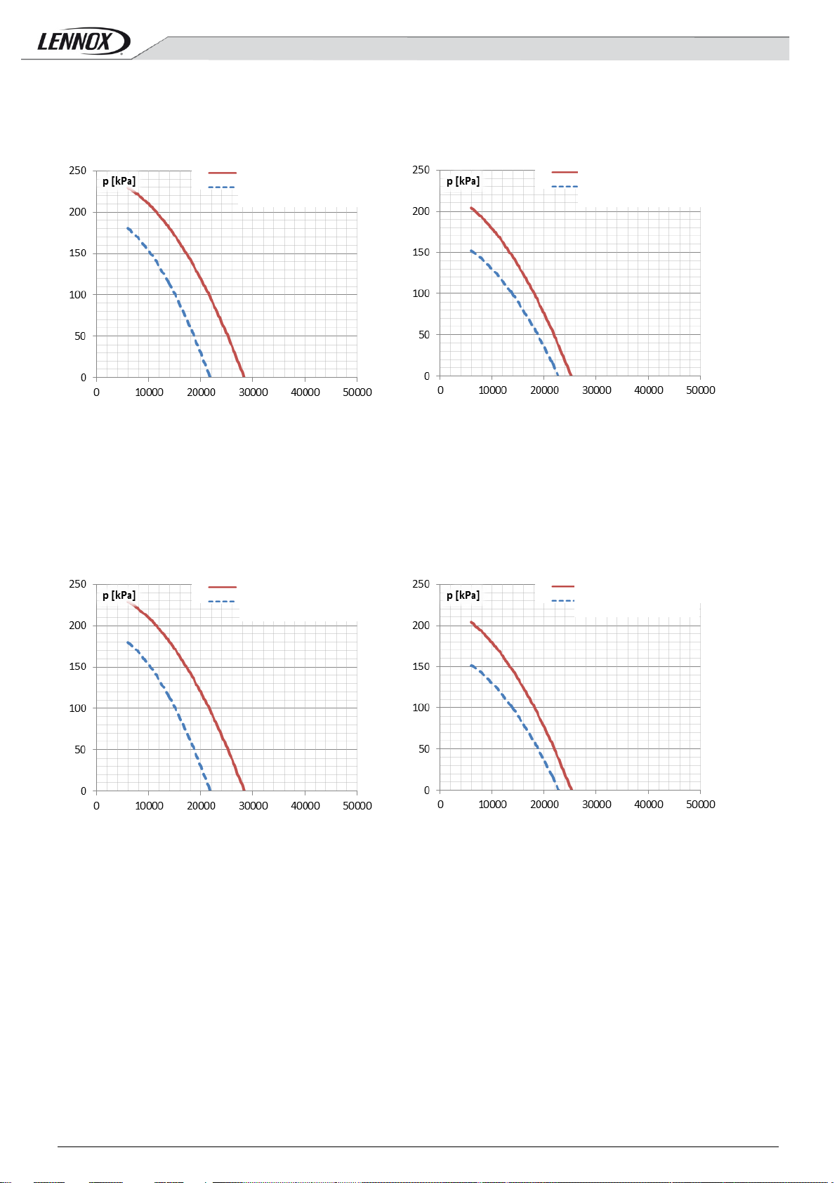
Available Head pressure [kPa] for AAH041 S pumps
Pure water flow rate [l/h]
Pure water flow rate [l/h]
abs. nom. power LP: 1. 1 [kW] / abs. nom. power HP: 1.5 [kW]
abs. nom. power LP: 0. 9 [kW] abs. nom. power HP: 0.9 [kW]
abs. nom. curr ent LP: 2.5 [A] abs. nom. current HP: 3.2 [A]
abs. nom. curr ent LP: 2.7 [A] abs. nom. current HP: 2.7 [A]
Pure water flow rate [l/h]
Pure water flow rate [l/h]
abs. nom. power LP: 1. 1 [kW] / abs. nom. power HP: 1.5 [kW]
abs. nom. power LP: 0. 9 [kW] / abs. nom. power HP: 0.9 [kW]
abs. nom. curr ent LP: 2.5 [A] / abs. nom. current HP: 3.2 [A]
abs. nom. curr ent LP: 2.7 [A] / abs. nom. current HP: 2.7 [A]
High pressure Pump
High pressure Pump
Low Pressure pump
High pressure
High pressure
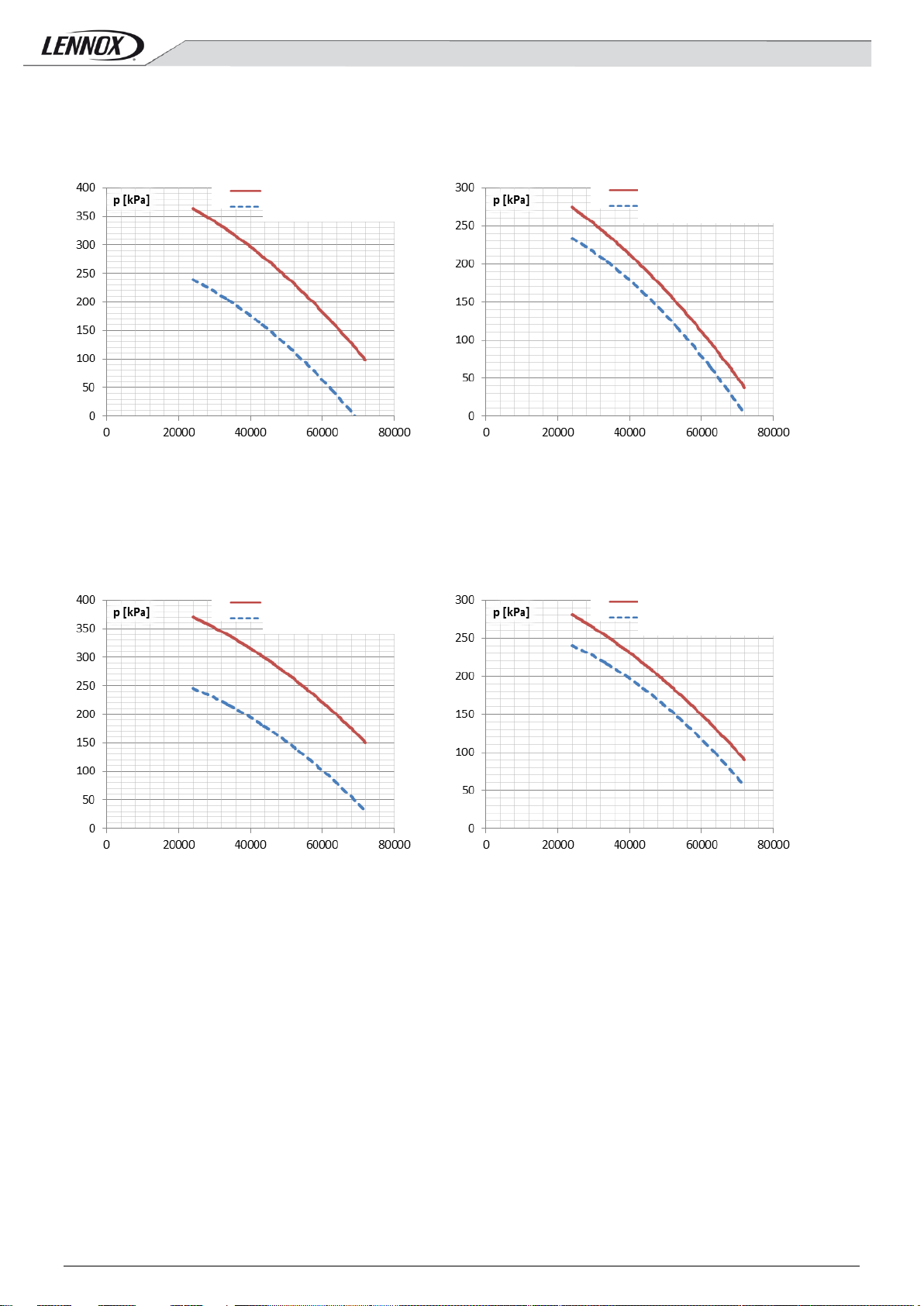
10.1 Characteristic curves of hydraulic pumps attached to units AQUA4 M and AQUA4 P
with standard noise levels: Version S
The graphs in these paragraphs express the available head pressure (net of the losses inside the units) of the high pressure (HP) and
low pressure (LP) pumps available wi th these machine, both on the utility circuit and on the recovery circuit, in relation to water flow
rate. Refer to t he “Use of glycol solutions” paragraph to assess the effect of glycol on the useful head provided by the pumps . Below are
the corrective coefficients to apply to the curves, calculated in pure water.
(single or normal/backup switching operation)
Low Pressure pump
Available Head pressure [kPa] for AAH041 S pumps
(parallel operation)
Available Head pressure [kPa] for AAH051 S pumps
(single or normal/backup switching operation)
Pump
Available Head pressure [kPa] for AAH051 S pumps
(parallel operation)
Pump
AQUA4–AGU-1405-E - 26 -
Page 29
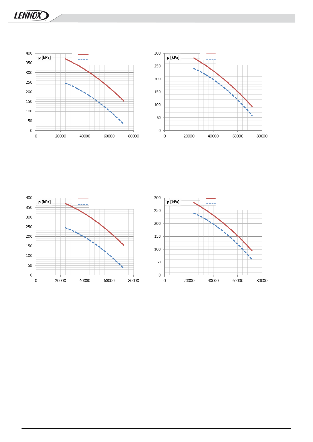
Available Head pressure [kPa] for AAH061 S pumps
Available Head pressure [kPa] for AAH061 S pumps
Pure water flow rate [l/h]
Pure water flow rate [l/h]
abs. nom. power LP: 1. 1 [kW] / abs. nom. power HP: 2.2 [kW]
abs. nom. power LP: 0. 9 [kW] / abs. nom. power HP: 0.9 [kW]
abs. nom. curr ent LP: 2.5 [A] / abs. nom. current HP: 4.8 [A]
abs. nom. curr ent LP: 2.7 [A] / abs. nom. current HP: 2.7 [A]
Available Head pressure [kPa] for AAH071 S pumps
Available Head pressure [kPa] for AAH071 S pumps
Pure water flow rate [l/h]
Pure water flow rate [l/h]
abs. nom. power LP: 1. 1 [kW] / abs. nom. power HP: 2.2 [kW]
abs. nom. power LP: 0. 9 [kW] / abs. nom. power HP: 0.9 [kW]
abs. nom. curr ent LP: 2.5 [A] / abs. nom. current HP: 4.8 [A]
abs. nom. curr ent LP: 2.7 [A] / abs. nom. current HP: 2.7 [A]
High pressure
High pressure
High pressure
High pressure
(single or normal/backup switching operation)
Pump
(parallel operation)
Pump
(single or normal/backup switching operation)
Pump
(parallel operation)
Pump
AQUA4–AGU-1405-E - 27 -
Page 30

Available Head pressure [kPa] for AAH081 S pumps
Available Head pressure [kPa] for AAH081 S pumps
Pure water flow rate [l/h]
Pure water flow rate [l/h]
abs. nom. power LP: 1. 1 [kW] abs. nom. power HP: 2.2 [kW]
abs. nom. power LP: 0. 9 [kW] abs. nom. power HP: 0.9 [kW]
abs. nom. curr ent LP: 2.5 [A] abs. nom. current HP: 4.8 [A]
abs. nom. curr ent LP: 2.7 [A] abs. nom. current HP: 2.7 [A]
Pure water flow rate [l/h]
Pure water flow rate [l/h]
abs. nom. power LP: 1. 5 [kW] abs. nom. power HP: 2.2 [kW]
abs. nom. power LP: 1. 1 [kW] abs. nom. power HP: 1.5 [kW]
abs. nom. curr ent LP: 3.4 [A] abs. nom. current HP: 4.8 [A]
abs. nom. curr ent LP: 2.5 [A] abs. nom. current HP: 3.2 [A]
High pressure
High pressure
High pressure Pump
High pressure Pump
(single or normal/backup switching operation)
Pump
Available Head pressure [kPa] for AAH094 S pumps
(single or normal/backup switching operation)
(parallel operation)
Pump
Available Head pressure [kPa] for AAH94 S pumps
(parallel operation)
Low Pressure pump
Low Pressure pump
AQUA4–AGU-1405-E - 28 -
Page 31
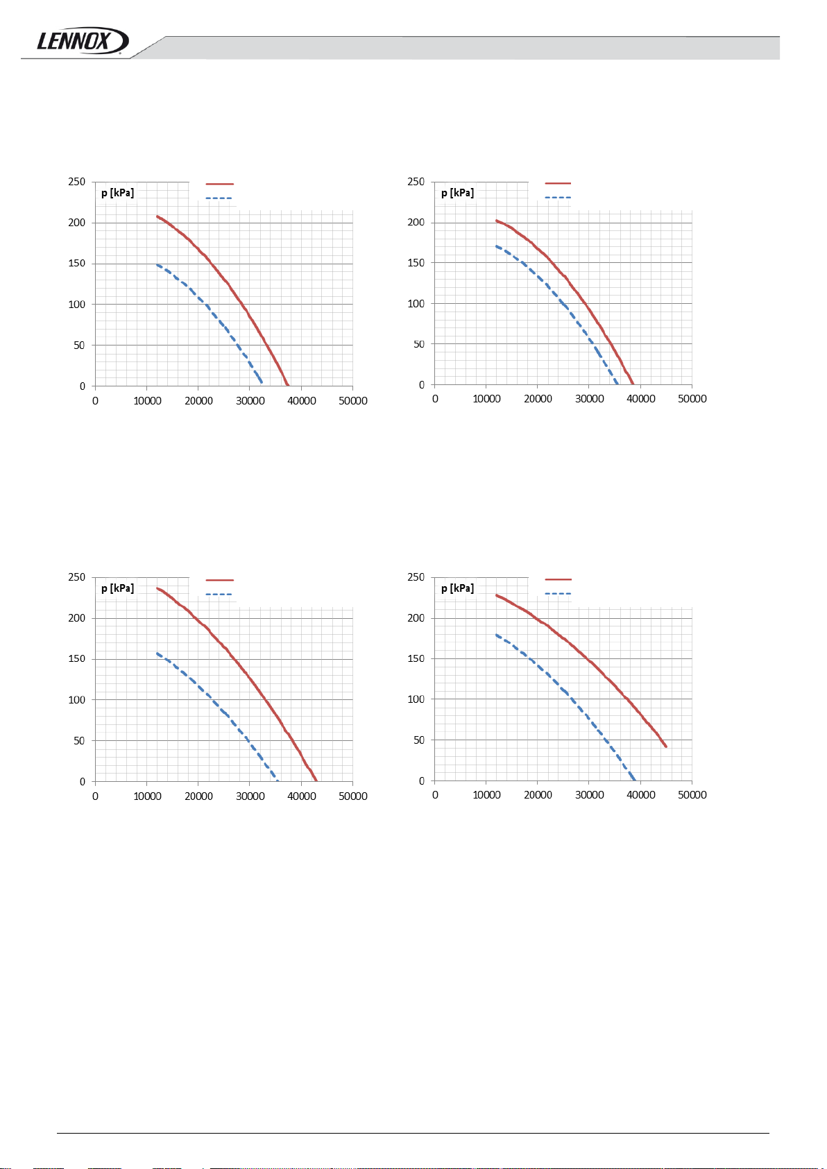
Available Head pressure [kPa] for AAH104 S pumps
Available Head pressure [kPa] for AAH104 S pumps
Pure water flow rate [l/h]
Pure water flow rate [l/h]
abs. nom. power LP: 1. 5 [kW] abs. nom. power HP: 2.2 [kW]
abs. nom. power LP: 1. 1 [kW] abs. nom. power HP: 1.5 [kW]
abs. nom. curr ent LP: 3.4 [A] abs. nom. current HP: 4.8 [A]
abs. nom. curr ent LP: 2.5 [A] abs. nom. current HP: 3.2 [A]
Available Head pressure [kPa] for AAH124 S pumps
Available Head pressure [kPa] for AAH124 S pumps
Pure water flow rate [l/h]
Pure water flow rate [l/h]
abs. nom. power LP: 1. 5 [kW] abs. nom. power HP: 3 [kW]
abs. nom. power LP: 1. 1 [kW] abs. nom. power HP: 2.2 [kW]
abs. nom. curr ent LP: 3.4 [A] abs. nom. current HP: 5.6 [A]
abs. nom. curr ent LP: 2.5 [A] abs. nom. current HP: 4.8 [A]
High pressure Pump
High pressure Pump
High pressure Pump
High pressure Pump
(single or normal/backup switching operation)
Low Pressure pump
(single or normal/backup switching operation)
(parallel operation)
Low Pressure pump
(parallel operation)
Low Pressure pump
Low Pressure pump
AQUA4–AGU-1405-E - 29 -
Page 32

Available Head pressure [kPa] for AAH144 S pumps
Available Head pressure [kPa] for AAH144 S pumps
Pure water flow rate [l/h]
Pure water flow r ate [l/h]
abs. nom. power LP: 2. 2 [kW] abs. nom. power HP: 3 [kW]
abs. nom. power LP: 1. 1 [kW] abs. nom. power HP: 2.2 [kW]
abs. nom. curr ent LP: 4.8 [A] abs. nom. current HP: 5.6 [A]
abs. nom. curr ent LP: 2.5 [A] abs. nom. current HP: 4.8 [A]
Available Head pressure [kPa] for AAH164 S pumps
Available Head pressure [kPa] for AAH164 S pumps
Pure water flow rate [l/h]
Pure water flow rate [l/h]
abs. nom. power LP: 2. 2 [kW] abs. nom. power HP: 3 [kW]
abs. nom. power LP: 1. 1 [kW] abs. nom. power HP: 2.2 [kW]
abs. nom. curr ent LP: 4.8 [A] abs. nom. current HP: 5.6 [A]
abs. nom. curr ent LP: 2.5 [A] abs. nom. current HP: 4.8 [A]
High pressure Pump
High pressure Pump
High pressure Pump
High pressure Pump
(single or normal/backup switching operation)
Low Pressure pump
(single or normal/backup switching operation)
(parallel operation)
Low Pressure pump
(parallel operation)
Low Pressure pump
Low Pressure pump
AQUA4–AGU-1405-E - 30 -
Page 33

Available Head pressure [kPa] for AAH194 S pumps
Available Head pressure [kPa] for AAH194 S pumps
Pure water flow rate [l/h]
Pure water flow rate [l/h]
abs. nom. power LP: 2. 8 [kW] abs. nom. power HP: 5.1 [kW]
abs. nom. power LP: 2 [ kW] abs. nom. power HP: 2.8 [kW]
abs. nom. curr ent LP: 4.8 [A] abs. nom. current HP: 9.2 [A]
abs. nom. curr ent LP: 3.4 [A] abs. nom. current HP: 4.8 [A]
Pure water flow rate [l/h]
Pure water flow rate [l/h]
abs. nom. power LP: 3. 7 [kW] abs. nom. power HP: 5.1 [kW]
abs. nom. power LP: 2 [ kW] abs. nom. power HP: 2.8 [kW]
abs. nom. curr ent LP: 6.8 [A] abs. nom. current HP: 9.2 [A]
abs. nom. current LP: 3.4 [A] abs. nom. current HP: 4.8 [A]
High pressure Pump
High pressure Pump
High pressure Pump
High pressure Pump
(single or normal/backup switching operation)
Low Pressure pump
Available Head pressure [kPa] for AAH194 S pumps
(single or normal/backup switching operation)
(parallel operation)
Low Pressure pump
Available Head pressure [kPa] for AAH194 S pumps
(parallel operation)
Low Pressure pump
Low Pressure pump
AQUA4–AGU-1405-E - 31 -
Page 34

Available Head pressure [kPa] for AAH244 S pumps
Available Head pressure [kPa] for AAH244 S pumps
Pure water flow rate [l/h]
Pure water flow rate [l/h]
abs. nom. power LP: 4 [ kW] abs. nom. power HP: 7.5 [kW]
abs. nom. power LP: 2. 8 [kW] abs. nom. power HP: 3.7 [kW]
abs. nom. curr ent LP: 9.2 [A] abs. nom. current HP: 12.5 [A]
abs. nom. curr ent LP: 4.8 [A] abs. nom. current HP: 6.8 [A]
Available Head pressure [kPa] for AAH274 S pumps
Available Head pressure [kPa] for AAH274 S pumps
Pure water flow rate [l/h]
Pure water flow rate [l/h]
abs. nom. power LP: 4 [ kW] abs. nom. power HP: 7.5 [kW]
abs. nom. power LP: 2. 8 [kW] abs. nom. power HP: 3.7 [kW]
abs. nom. curr ent LP: 9.2 [A] abs. nom. current HP: 12.5 [A]
abs. nom. curr ent LP: 4.8 [A] abs. nom. current HP: 6.8 [A]
High pressure Pump
High pressure Pump
High pressure Pump
High pressure Pump
(single or normal/backup switching operation)
Low Pressure pump
(single or normal/backup switching operation)
(parallel operation)
Low Pressure pump
(parallel operation)
Low Pressure pump
Low Pressure pump
AQUA4–AGU-1405-E - 32 -
Page 35

Available Head pressure [kPa] for AAH294 S pumps
Available Head pressure [kPa] for AAH294 S pumps
Pure water flow rate [l/h]
Pure water flow rate [l/h]
abs. nom. power LP: 4 [ kW] abs. nom. power HP: 7.5 [kW]
abs. nom. power LP: 2. 8 [kW] abs. nom. power HP: 3.7 [kW]
abs. nom. curr ent LP: 9.2 [A] abs. nom. current HP: 12.5 [A]
abs. nom. curr ent LP: 4.8 [A] abs. nom. current HP: 6.8 [A]
Available Head pressure [kPa] for AAH324 S pumps
Available Head pr essure [kPa] for AAH324 S pumps
Pure water flow rate [l/h]
Pure water flow rate [l/h]
abs. nom. power LP: 4 [ kW] abs. nom. power HP: 7.5 [kW]
abs. nom. power LP: 2. 8 [kW] abs. nom. power HP: 3.7 [kW]
abs. nom. curr ent LP: 9.2 [A] abs. nom. current HP: 12.5 [A]
abs. nom. curr ent LP: 4.8 [A] abs. nom. current HP: 6.8 [A]
High pressure Pump
High pressure Pump
High pressure Pump
High pressure Pump
(single or normal/backup switching operation)
Low Pressure pump
(single or normal/backup switching operation)
(parallel operation)
Low Pressure pump
(parallel operation)
Low Pressure pump
Low Pressure pump
AQUA4–AGU-1405-E - 33 -
Page 36

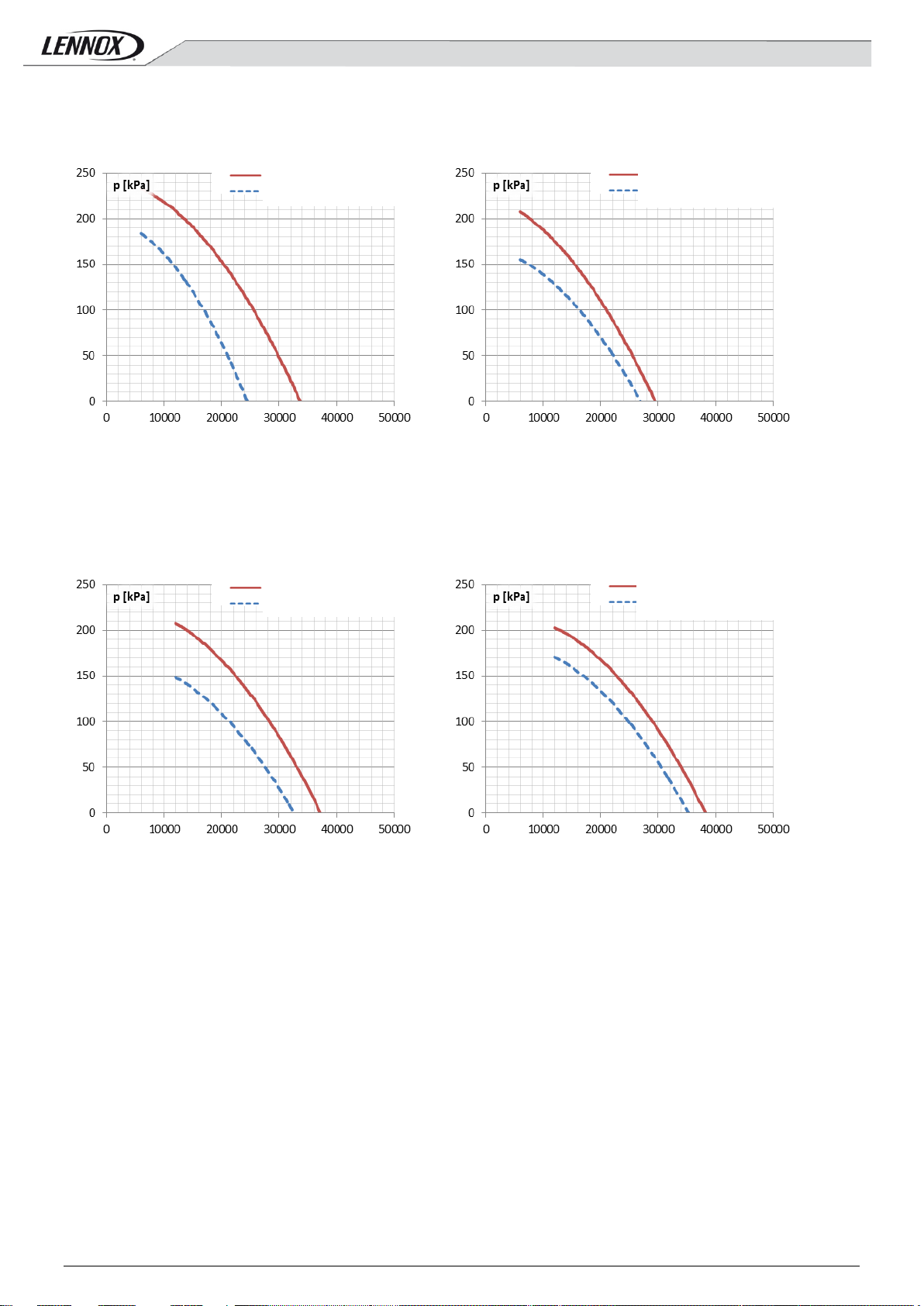
Available Head pressure [kPa] for AAH041 L pumps
Available Head pressure [kPa] for AAH041 L pumps
Pure water flow rate [l/h]
Pure water flow rate [l/h]
abs. nom. power LP: 1. 1 [kW] abs. nom. power HP: 1.5 [kW]
abs. nom. power LP: 0. 9 [kW] abs. nom. power HP: 0.9 [kW]
abs. nom. curr ent LP: 2.5 [A] abs. nom. current HP: 3.2 [A]
abs. nom. curr ent LP: 2.7 [A] abs. nom. current HP: 2.7 [A]
Pure water flow rate [l/h]
Pure water flow rate [l/h]
abs. nom. power LP: 1.1 [kW] abs. nom. power HP: 1.5 [kW]
abs. nom. power LP: 0. 9 [kW] abs. nom. power HP: 0.9 [kW]
abs. nom. curr ent LP: 2.5 [A] abs. nom. current HP: 3.2 [A]
abs. nom. curr ent LP: 2.7 [A] abs. nom. current HP: 2.7 [A]
High pressure Pump
High pressure Pump
High pressure Pump
High pressure Pump
10.2 Characteristic curves of hydraulic pumps attached to units AQUA4 M and AQUA4 P
with low sound levels: Version L
(single or normal/backup switching operation)
Low Pressure pump
Available Head pressure [kPa] for AAH051 L pumps
(single or normal/backup switching operation)
(parallel operation)
Low Pressure pump
Available Head pressure [kPa] for AAH051 L pumps
(parallel operation)
Low Pressure pump
Low Pressure pump
AQUA4–AGU-1405-E - 34 -
Page 37

Available Head pressure [kPa] for AAH061 L pumps
Available Head pressure [kPa] for AAH061 L pumps
Pure water flow rate [l/h]
Pure water flow rate [l/h]
abs. nom. power LP: 1. 1 [kW] abs. nom. power HP: 2.2 [kW]
abs. nom. power LP: 0. 9 [kW] abs. nom. power HP: 0.9 [kW]
abs. nom. curr ent LP: 2.5 [A] abs. nom. current HP: 4.8 [A]
abs. nom. curr ent LP: 2.7 [A] abs. nom. current HP: 2.7 [A]
Available Head pressure [kPa] for AAH071 L pumps
Available Head pressure [kPa] for AAH071 L pumps
Pure water flow rate [l/h]
Pure water flow r ate [l/h]
abs. nom. power LP: 1. 1 [kW] abs. nom. power HP: 2.2 [kW]
abs. nom. power LP: 0. 9 [kW] abs. nom. power HP: 0.9 [kW]
abs. nom. curr ent LP: 2.5 [A] abs. nom. current HP: 4.8 [A]
abs. nom. curr ent LP: 2.7 [A] abs. nom. current HP: 2.7 [A]
High pressure Pump
High pressure Pump
High pressure Pump
High pressure Pump
(single or normal/backup switching operation)
Low Pressure pump
(single or normal/backup switching operation)
(parallel operation)
Low Pressure pump
(parallel operation)
Low Pressure pump
Low Pressure pump
AQUA4–AGU-1405-E - 35 -
Page 38
Available Head pressure [kPa] for AAH081 L pumps
Available Head pressure [kPa] for AAH081 L pumps
Pure water flow rate [l/h]
Pure water flow rate [l/h]
abs. nom. power LP: 1. 1 [kW] abs. nom. power HP: 2.2 [kW]
abs. nom. power LP: 0. 9 [kW] abs. nom. power HP: 0.9 [kW]
abs. nom. curr ent LP: 2.5 [A] abs. nom. current HP: 4.8 [A]
abs. nom. curr ent LP: 2.7 [A] abs. nom. cur rent HP: 2.7 [A]
Available Head pressure [kPa] for AAH094 L pumps
Available Head pressure [kPa] for AAH094 L pumps
Pure water flow r ate [l/h]
Pure water flow rate [l/h]
abs. nom. power LP: 1. 5 [kW] abs. nom. power HP: 2.2 [kW]
abs. nom. power LP: 1. 1 [kW] abs. nom. power HP: 1.5 [kW]
abs. nom. curr ent LP: 3.4 [A] abs. nom. current HP: 4.8 [A]
abs. nom. curr ent LP: 2.5 [A] abs. nom. current HP: 3.2 [A]
High pressure Pump
High pressure Pump
High pressure Pump
High pressure Pump
(single or normal/backup switching operation)
Low Pressure pump
(single or normal/backup switching operation)
(parallel operation)
Low Pressure pump
(parallel operation)
Low Pressure pump
Low Pressure pump
AQUA4–AGU-1405-E - 36 -
Page 39

Available Head pressure [kPa] for AAH104 L pumps
Available Head pressure [kPa] for AAH104 L pumps
Pure water flow rate [l/h]
Pure water flow rate [l/h]
abs. nom. power LP: 1. 5 [kW] abs. nom. power HP: 2.2 [kW]
abs. nom. power LP: 1. 1 [kW] abs. nom. power HP: 1.5 [kW]
abs. nom. curr ent LP: 3.4 [A] abs. nom. current HP: 4.8 [A]
abs. nom. curr ent LP: 2.5 [A] abs. nom. current HP: 3.2 [A]
Pure water flow rate [l/h]
Pure water flow rate [l/h]
abs. nom. power LP: 1. 5 [kW] abs. nom. power HP: 3 [kW]
abs. nom. power LP: 1. 1 [kW] abs. nom. power HP: 2.2 [kW]
abs. nom. curr ent LP: 3.4 [A] abs. nom. current HP: 5.6 [A]
abs. nom. curr ent LP: 2.5 [A] abs. nom. current HP: 4.8 [A]
High pressure Pump
High pressure Pump
High pressure Pump
High pressure Pump
(single or normal/backup switching operation)
Low Pressure pump
Available Head pressure [kPa] for AAH124 L pumps
(single or normal/backup switching operation)
(parallel operation)
Low Pressure pump
Available Head pressure [kPa] for AAH124 L pumps
(parallel operation)
Low Pressure pump
Low Pressure pump
AQUA4–AGU-1405-E - 37 -
Page 40

Available Head pressure [kPa] for AAH144 L pumps
Available Head pressure [kPa] for AAH144 L pumps
Pure water flow rate [l/h]
Pure water flow rate [l/h]
abs. nom. power LP: 2. 2 [kW] abs. nom. power HP: 3 [kW]
abs. nom. power LP: 1. 1 [kW] abs. nom. power HP: 2.2 [kW]
abs. nom. curr ent LP: 4.8 [A] abs. nom. current HP: 5.6 [A]
abs. nom. curr ent LP: 2.5 [A] abs. nom. current HP: 4.8 [A]
Available Head pressure [kPa] for AAH164 L pumps
Available Head pr essure [kPa] for AAH164 L pumps
Pure water flow rate [l/h]
Pure water flow rate [l/h]
abs. nom. power LP: 2. 2 [kW] abs. nom. power HP: 3 [kW]
abs. nom. power LP: 1. 1 [kW] abs. nom. power HP: 2.2 [kW]
abs. nom. curr ent LP: 4.8 [A] abs. nom. current HP: 5.6 [A]
abs. nom. curr ent LP: 2.5 [A] abs. nom. current HP: 4.8 [A]
High pressure Pump
High pressure Pump
High pressure Pump
High pressure Pump
(single or normal/backup switching operation)
Low Pressure pump
(single or normal/backup switching operation)
(parallel operation)
Low Pressure pump
(parallel operation)
Low Pressure pump
Low Pressure pump
AQUA4–AGU-1405-E - 38 -
Page 41

Available Head pressure [kPa] for AAH194 L pumps
Available Head pressure [kPa] for AAH194 L pumps
Pure water flow rate [l/h]
Pure water flow rate [l/h]
abs. nom. power LP: 2. 8 [kW] abs. nom. power HP: 5.1 [kW]
abs. nom. power LP: 2 [ kW] abs. nom. power HP: 2.8 [kW]
abs. nom. curr ent LP: 4.8 [A] abs. nom. current HP: 9.2 [A]
abs. nom. curr ent LP: 3.4 [A] abs. nom. current HP: 4.8 [A]
Available Head pressure [kPa] for AAH214 L pumps
Available Head pressure [kPa] for AAH214 L pumps
Pure water flow rate [l/h]
Pure water flow rate [l/h]
abs. nom. power LP: 3. 7 [kW] abs. nom. power HP: 5.1 [kW]
abs. nom. power LP: 2 [ kW] abs. nom. power HP: 2.8 [kW]
abs. nom. curr ent LP: 6.8 [A] abs. nom. current HP: 9.2 [A]
abs. nom. curr ent LP: 3.4 [A] abs. nom. current HP: 4.8 [A]
High pressure Pump
High pressure Pump
High pressure Pump
High pressure Pump
(single or normal/backup switching operation)
Low Pressure pump
(single or normal/backup switching operation)
(parallel operation)
Low Pressure pump
(parallel operation)
Low Pressure pump
Low Pressure pump
AQUA4–AGU-1405-E - 39 -
Page 42
Available Head pressure [kPa] for AAH244 L pumps
Available Head pressure [kPa] for AAH244 L pumps
Pure water flow rate [l/h]
Pure water flow rate [l/h]
abs. nom. power LP: 4 [ kW] abs. nom. power HP: 7.5 [kW]
abs. nom. power LP: 2. 8 [kW] abs. nom. power HP: 3.7 [kW]
abs. nom. curr ent LP: 9.2 [A] abs. nom. current HP: 12.5 [A]
abs. nom. curr ent LP: 4.8 [A] abs. nom. current HP: 6.8 [A]
Pure water flow rate [l/h]
Pure water flow rate [l/h]
abs. nom. power LP: 4 [ kW] abs. nom. power HP: 7.5 [kW]
abs. nom. power LP: 2. 8 [kW] abs. nom. power HP: 3.7 [kW]
abs. nom. curr ent LP: 9.2 [A] abs. nom. current HP: 12.5 [A]
abs. nom. curr ent LP: 4.8 [A] abs. nom. current HP: 6.8 [A]
High pressure Pump
High pressure Pump
High pressure Pump
High pressure Pump
(single or normal/backup switc hing operation)
Low Pressure pump
Available Head pressure [kPa] for AAH274 L pumps
(single or normal/backup switching operation)
(parallel operation)
Low Pressure pump
Available Head pressure [kPa] for AAH274 L pumps
(parallel operation)
Low Pressure pump
Low Pressure pump
AQUA4–AGU-1405-E - 40 -
Page 43
Available Head pressure [kPa] for AAH294 L pumps
Available Head pressure [kPa] for AAH294 L pumps
Pure water flow rate [l/h]
Pure water flow rate [l/h]
abs. nom. power LP: 4 [ kW] abs. nom. power HP: 7.5 [kW]
abs. nom. power LP: 2. 8 [kW] abs. nom. power HP: 3.7 [kW]
abs. nom. curr ent LP: 9.2 [A] abs. nom. current HP: 12.5 [A]
abs. nom. curr ent LP: 4.8 [A] abs. nom. current HP: 6.8 [A]
Available Head pressure [kPa] for AAH324 L pumps
Available Head pressure [kPa] for AAH324 L pumps
Pure water flow rate [l/h]
Pure water flow rate [l/h]
abs. nom. power LP: 4 [ kW] abs. nom. power HP: 7.5 [kW]
abs. nom. power LP: 2.8 [kW] abs. nom. power HP: 3.7 [kW]
abs. nom. curr ent LP: 9.2 [A] abs. nom. current HP: 12.5 [A]
abs. nom. curr ent LP: 4.8 [A] abs. nom. current HP: 6.8 [A]
High pressure Pump
High pressure Pump
High pressure Pump
High pressure Pump
(single or normal/backup switching operation)
Low Pressure pump
(single or normal/backup switc hing operation)
(parallel operation)
Low Pressure pump
(parallel operation)
Low Pressure pump
Low Pressure pump
AQUA4–AGU-1405-E - 41 -
Page 44

11 Overview Diagrams
AAH PS PL MS ML 041 and 051 Box F1+
AAH PS PL MS ML 061, 071 and 081 Box F2+
AQUA4–AGU-1405-E - 42 -
Page 45

AAH PS PL MS ML 094 and 104 Box F3+
AAH PS PL MS ML 124, 144, 164 and 194 Box F4
AQUA4–AGU-1405-E - 43 -
Page 46

AAH PS PL MS ML 214 and 244 Box F5
AAH PS PL MS ML 274, 294 and 324 Box F6
AQUA4–AGU-1405-E - 44 -
Page 47

Warning: Duri ng all lifting operati ons make sure the unit is firmly anchored, t o prevent it fr om tilting or
falling.
12 Installation
12.1 For further information see the installation, operating and maintenance manual: IOM
12.2 Preliminary procedures
The machine left the factory in perfect conditions, however when receiving the unit verify its integrity. Immediately report any dam age to
the carrier and write it down on the Deliver y Note before signing it.
LENNOX or its commercial reference mus t be promptly notifi ed regarding the extent and type of damage. The Customer must submit a
written report describing any significant damage.
Lifting and transport
While the unit is being unloaded and posit ioned, utmost care must be taken to avoid abrupt or violent manoeuvres. Be very c areful
when transporting it inside rooms. Do not use the unit com ponents as anchors.
The unit should be li fted with Ø1½” GAS s teel pipes at least 3 mm thick. Insert them, on the base side members (see fig. below), i nto
the holes marked wi th stickers. The pipes, which should protrude by at least 300 mm from all sides, must be secured with r opes of
equal length to the lifting hook (provide stops at the ends of the pipes to prevent t he ropes from sli pping off because of the weight).
Use ropes or belts long enough to extend bey ond the height of the m achine. Place spac er bars and boards on top of the unit to avoid
damaging the sides and the top of the unit.
AQUA4–AGU-1405-E - 45 -
Page 48

1.0 m
1.0 m
1.5 m
1.5 m
When installing the unit, for saf ety purposes, make sure that the room temperature does not exceed 50°C
Should refrigerant leak in the vicinity of open flames or in a room without sufficient ventilation, it could catch
Unpacking
Carefully remove any packaging to avoi d damaging the machine. Different packaging materials are used: wood, cardboar d, nylon etc.
Keep them separate and dispose of them at appropriate waste d isposal or recycling facilities in order to minimise the environmental
impact.
Once the machine is positioned, loosen the bolts to remove the pallet. Then push the unit from below and s lide it to its proper position.
Siting
Bear in mind the foll ow ing when choosing t he best site for installing the unit and the connections:
- Size and origin of water pipes;
- Location of power supply;
- Access for maintenance or repairs;
- Stability of the supporting surface.
All the models of the AQUA
components and hot par ts are specially designed, the AQUA
It is advisable to place a vibration damping system between the base frame and the supporting surface.
fire and the combustion by products could be harmful to people.
4
series have been des igned and built for outdoor install ations. Since soundproofing and protections of
4
series models do not need to be kept inside.
Installation clearan c e requ irements
It is important to provide an adequate volum e of air on the intake and delivery sides of the condensing/evapor ating finned coils. It is
essential to pr event air recirculation between intake and delivery, as this may affect unit per formance or inter rupt normal operation. For
this reason provide the following c learances (see figure on this page):
- hydraulic connections/back side: at least 1 meter to provide room for water connections and/or maintenance to the flow switch
expansion vessel tank pump unit.
- electric panel side: at least 1 meter to guarantee access f or inspections and/or for maintenance of cooling components
- finned-pack condenser side: at least 1.5 meters to ensure proper air circul ation as well as acc ess (even from the side) to the
compressor compartment
- upper side: during expulsion there must be no obstacles.
back
Top view of the unit
(with unit on or of f).
front
12.3 Water connections
When setting up the w ater circuits for the evaporator follow the instructions below and comply with national or local standards (use the
diagrams attached to this document as reference). Fit the piping to the cooler with flexi ble joints to dampen vibrations an d to
compensate for thermal exp ansion. Refer to the technical data table for the type and dimensions of the hydr aulic connections.
It is recommended t o install the following components on the pi ping:
AQUA4–AGU-1405-E - 46 -
Page 49

NsSh
Cc
V
×
∆Τ××
∆×
=
ρ
τ
Inertial Tank
Ts °C
Inlet water T
Outlet water T
The tank is not designed to withstand vacu u m pressures greater than 0.15 bar. For this reason, make sure that
Warning: Never per form hydraulic connection operations with open flames near or inside the unit.
The AQUA4 units are supplied as standard with a device that controls the water flow (paddle flow switch
It is mandatory to i nstall a metal net fi lter on the water inlet piping.
It is extremely important that the wat er inlet is connected at the height of the “Water Inlet” si gn.
The water circuit must guarantee a cons tant nominal flow rate of water (+/- 15%) to the evaporator in all
- temperature and pressure indicators for routine maintenance and inspect ions of the unit. Pressure control on the water side allows
expansion vessel operation to be checked and any water leaks in the system to be detected in advance.
- Sumps on inlet and outlet piping for meas uring temperatures , and for directly vi ewing the operating temperatures. They can also
be viewed on the display on board the unit (if pCO).
- Shut-off valves (gate valves) to isolate the unit from the water circuit for mai ntenance.
- Air vent valves, placed on the higher parts of the water circuit, that bleed the air. The internal pipes of the machine are fitted with
manual air vent valves to bleed the unit: this operation can only be carri ed out when the unit is disconnected from the power
supply
- discharge cock and, if necessary, drain t ank to empty the system for maintenance or s easonal stops
- For process applications, it is recommended to install a decoupling heat exchanger, which avoids the fouling of the heat
exchangers
- It is mandatory to ins tall a metal net filter (inlet pipe), with a mesh not above 1 mm, to protect the heat exchanger from slag or
impurities i nside the pipes. This is especially impor tant during commissioning.
Water connection to evaporator
If not, the evaporator would be exposed to the risk of freezi ng, since the anti-freeze thermostat would not be able to perfor m its function.
Furthermore, in the cooling mode, c ountercurrent circulation would not be act ivated. Additionally, this posi tion does not enable consent
of the water flow control device.
The dimensions and position of the water connections are pr ovided in the dimensional tables and overall drawings.
The ON/OFF-type compressors work intermittently, since the cooling power required by the utility is not generally the same as that
supplied by the compressor. In syst em s containing litt le water, in which the thermal inertia i s low, verify that the wat er content of the
delivery secti on (to users) satisfies the equation below:
operating condit ions.
V = water cont ent in user section [m3]
Sh = specific heat of fluid [J/(kg/°C)] e.g. 2090 [J/(kg/°C)] for water
ρ = density of fluid [kg/m3] e.g. 1000 [kg/m3] for w ater
Dτ = minimum time between 2 compressor restarts [s] [s] e.g. 120
DT = admissible differential on water T [°C] e.g. 4 [°C]
Cc = Cooling Capacity [W]
Ns = N° of capacity control steps
supplied on board the machine).
Any tampering with this device will i mmediately invalidate the warranty.
How to fill up the tank and/or the pumps (if required by the system)
It is extremely important that the installer follow and verify this procedur e step-by-step to pr event the risk of tank implosion or pump
cavitation:
the pressure on the pum p intake side, where the expansion vessel is positioned, is always above 0.5 bar with
pump running. This helps reduce the risk of cavitation.
AQUA4–AGU-1405-E - 47 -
Page 50

Minimum temperature of
produced water
Percentage in weight of
ethylene glycol
Freezing temperature of
mixture
The pump, when an integr al part of the supply, must be started before the cooler starts and stopped after it
The machine must operate within the above values, or the warranty will be invalidated.
The size of the cable and line protecti ons must conform to the specifications provided in the wiring diagr am .
Before carrying out any operation on electrical parts , make sure that the power supply is disconnected.
- Drain the expansion vessel until the pres sure reaches 0.5 bar
- Fill the system and pressurise it to appro ximately + 1 bar in pump suction (pump stopped)
- Bleed the system
- Check the pump sucti on pressure (approximat ely 1 bar) and star t up the system
- Stop the pump after 15-30 minutes. Repeat the procedure from st ep 3 until no more air system noise can be heard.
12.4 Electrical connectio n s
Check that the mai ns electricity suppl y is compatible with the specificati ons (voltage, number of phases, frequency) shown on the unit
rating plate.
The supply voltage m ust not fluctuate more than ±5% and the im balance between phases must always be below 2%.
Cary out the electrical connections following the wir ing diagram provided with the unit, as well as current regulations.
An earth connection is mandatory: The installer must connect the earth wire to the earth terminal on the electrical panel (yellow and
green wire).
The power supply to the control circuit is shunted from the power line through an electric panel transformer.
The control circuit is protected by fuses or automatic switches, depending on the size of the unit.
12.5 Electric connections of the circulation pump
All the units of the LER series are provided w ith a voltage-fr ee contact on the electrical panel that powers the pump start consent.
stops (minimum recommended start del ay: 60 seconds). I f it is connected to the electric panel term inal, this
function is already performed by the onboard microproc essor
Remote Controls
To remotely switch on and switch off t he unit, remove the jumper between the contacts and connect the remote control to the terminals
(see attached wiring diagram). Enable the “REMOTE” function with the elec tric panel switch.
Remote Summer-Winter switching (AQUA4 M Versions )
To remotely switch the unit from the s um m er to the winter modes, remove the jumper bet ween the contacts and connect the remote
control to the t erminals (see attached w iring diagram). Enable the “REMOTE” f unction with the electric panel switch.
The diagrams were pl otted with a temperat ure differential at the plate exchang ers (water circuit) of 5°C
12.6 Use of glycol solutions
Water can be produced at temperatures bel ow 5°C (up to -10°C) using glycol solutions. This lowers the freezing point as shown in the
following table:
5 °C 2°C -1 °C -5°C -10 °C
0 % 10 % 15% 25 % 30 %
0 °C -4 °C - 8 °C -14 °C -18 °C
For solution concentrations up to 30% in volume of glycol, the drop in thermodynami c circuit performance is minor.
The AQUA
4
units are not guaranteed for applicat ions in circuits with propylene glycol m ixtures.
12.7 Operating and storage limits
- Heat transfer fl uid: water or mixtures of water and ethylene glycol (max. 30% in volume)
AQUA4–AGU-1405-E - 48 -
Page 51

- Maximum water side pressure: = 3 bar
- Maximum pressure on high pressure circuit R410A = 42 bar-r
- Maximum pressure on low pressure circ uit R410A = 29 bar-r (*)
- Power supply voltage: = +/- 10% compared to plate voltage
- Maximum storage T = + 50 °C
- Minimum storage T = - 20 °C (limit set by on-board electr oni cs)
(*) this value can only be reached during storage and determines the saturation pressure of 29 bar-r of the refrigerant on the low
pressure side of the circuit (value which determines it s limits).
AQUA4–AGU-1405-E - 49 -
Page 52

SALES OFFICES :
lennoxemeia.com
BELGIUM AND LUXEMBOURG
+ 32 3 633 3045
FRANCE
+33 1 64 76 23 23
GERMANY
+49 (0) 211 950 79 600
ITALY
+ 39 02 495 26 200
NETHERLANDS
+ 31 332 471 800
POLAND
+48 22 58 48 610
RUSSIA
+7 495 626 56 53
SPAIN
+34 915 401 810
UKRAINE
+38 044 585 59 10
UNITED KINGDOM AND IRELAND
+44 1604 669 100
OTHER COUNTRIES :
PORTUGAL
+351 229 066 050
AQUA4-AGU-1405-E
LENNOX DISTRIBUTION
+33 4 72 23 20 20
Due to Lennox’s ongoing commitment to quality, the specifi cations,
ratings and dimensions are subject to change without notice and
without incurring liability.
Improper installation, adjustment, alteration, service or
maintenance can cause property damage or personal injury.
Installation and service must be performed by a qualifi ed installer
and servicing agency
 Loading...