

Page 1

7.3
Hardware Installation Guide
Page 2

Lenel® OnGuard® 7.3 Hardware Installation Guide
This guide is item number DOC-600, revision 7.011, August 2016.
© 2016 United Technologies Corporation. All rights reserved.
Lenel®, OnGuard® and Prism® (Registered trademarks of UTC Fire & Security Americas Corporation, Inc.) Lenel
is a part of UTC Climate, Controls & Security, a unit of United Technologies Corporation.All trademarks are the
property of their respective owners.
Information in this document is subject to change without notice. No part of this document may be reproduced or
transmitted in any form or by any means, electronic or mechanical, for any purpose, without the express written
permission of UTC Fire & Security Americas Corporation, Inc.
Non-English versions of Lenel documents are offered as a service to our global audiences. We have attempted to
provide an accurate translation of the text, but the official text is the English text, and any differences in the
translation are not binding and have no legal effect.
The software described in this document is furnished under a license agreement and may only be used in
accordance with the terms of that agreement.
Crystal Reports for Windows is a trademark of Crystal Computer Services, Inc.
OnGuard includes ImageStream® Graphic Filters. © 2002 eBT International, Inc. (f/k/a Inso Corporation). All
rights reserved. ImageStream Graphic Filters and ImageStream are registered trademarks of eBT International, Inc.
(f/k/a Inso Corporation).
Integral and FlashPoint are trademarks of Integral Technologies, Inc.
Portions of this product were created using LEADTOOLS ©1991-2011, LEAD Technologies, Inc. ALL RIGHTS
RESERVED. Portions of this product are licensed under US patent 5,327,254 and foreign counterparts.
Active Directory, Microsoft, SQL Server, Windows, and Windows Server are either registered trademarks or
trademarks of Microsoft Corporation in the United States and/or other countries.
Oracle is a registered trademark of Oracle and/or its affiliates. Other names may be trademarks of their respective
owners.
Other product names mentioned may be trademarks or registered trademarks of their respective companies and are
hereby acknowledged.
Warrant y
UTC Fire & Security Americas Corporation, Inc. ("Lenel") warrants that the product is free from defects in
material and workmanship under normal use and service with proper maintenance for one year from the date of
factory shipment. Lenel assumes no responsibility for products damaged by improper handling, misuse, neglect,
improper installation, over-voltages, repair, alteration, or accident. This warranty is limited to the repair or
replacement of the defective unit. In no event shall Lenel be liable for loss of use or consequential damages of any
kind, however occasioned. There are no expressed warranties other than those set forth herein. Warranty expressly
excludes third party additions, deletions and/or upgrades to this product, including those contained herein. Lenel
does not make, nor intends, nor does it authorize any agent or representative to make any other warranties or
implied warranties, and expressly excludes and disclaims all implied warranties of merchantability or fitness for a
particular purpose Returned units are repaired or replaced from a stock of reconditioned units. All returns must be
accompanied by a return authorization number (RMA) obtained from the Lenel customer service department prior
to returning or exchanging any product. The RMA number must appear on the outside of the shipping box and on
the packing slip. Any items returned without an RMA number will not be accepted and will be returned at the
customer's expense. All returns must have transportation, insurance, and custom brokers' fees prepaid.
Liability
It is expressly understood and agreed that the interface should only be used to control exits from areas where an
alternative method for exit is available. This product is not intended for, nor is rated for operation in life-critical
control applications. Lenel is not liable under any circumstances for loss or damage caused by or partially caused
by the misapplication or malfunction of the product. Lenel's liability does not extend beyond the purchase price of
the product.
Page 3

Hardware Installation Guide
Table of Contents
Hardware Installation Guidelines .......................................17
1. Inputs, Outputs and Interface Signals .................................................. 19
1.1 Power Inputs ....................................................................................................... 19
1.2 Alarm Inputs ....................................................................................................... 20
1.3 Reader Inputs/Outputs ....................................................................................... 20
1.4 Relay Outputs ..................................................................................................... 20
1.5 RS-485 Communication Overview ...................................................................... 20
1.6 RS-232 Interfaces ............................................................................................... 23
2. System Wiring and Other Considerations ............................................ 24
2.1 General Wiring Considerations ........................................................................... 24
2.2 Mounting ............................................................................................................. 29
2.3 Ground Wiring .................................................................................................... 36
2.4 Alarm Input Wiring .............................................................................................. 37
2.5 RS-485 Communication Wiring .......................................................................... 37
2.6 RS-232 Communication Wiring .......................................................................... 40
2.7 Weatherproofing ................................................................................................. 40
2.8 Relay Contact Protection .................................................................................... 41
3. System Turn-Up Considerations .......................................................... 43
3.1 Device Configuration Checks ............................................................................. 43
3.2 Ground Potential Difference Checks Before Connecting .................................... 44
4. Maintenance ........................................................................................ 45
4.1 Firmware Updates .............................................................................................. 46
4.2 AES/Extended Firmware .................................................................................... 46
5. UL/ULC Certified Installations .............................................................. 47
5.1 Power ................................................................................................................. 49
5.2 Typical Combinations for UL Installations ........................................................... 49
5.3 UL/ULC Requirements ....................................................................................... 53
5.4 CAN/ULC-S319-05 Requirements ...................................................................... 54
6. EN Certified Readers ........................................................................... 55
7. Troubleshooting ................................................................................... 56
LNL-500 Intelligent System Controller ............................... 59
8. Overview of the LNL-500 ..................................................................... 61
revision 7 — 3
Page 4

Table of Contents
8.1 Interfaces ............................................................................................................ 61
8.2 The Intelligent System Controller Board ............................................................. 61
9. Installation ............................................................................................63
9.1 Wiring ................................................................................................................. 63
10. Configuration ..................................................................................... 69
10.1 Setting DIP Switches ........................................................................................ 69
10.2 Installing Jumpers ............................................................................................. 71
11. Maintenance ...................................................................................... 72
11.1 Verification ........................................................................................................ 72
11.2 Replace Memory Backup Battery ..................................................................... 72
12. Specifications ..................................................................................... 73
LNL-1000 Intelligent System Controller .............................75
13. Overview of the LNL-1000 .................................................................77
13.1 Interfaces .......................................................................................................... 77
13.2 The ISC Board .................................................................................................. 78
14. Installation ..........................................................................................79
14.1 Wiring ............................................................................................................... 79
15. Configuration ..................................................................................... 86
15.1 Setting DIP Switches ........................................................................................ 86
15.2 Installing Jumpers ............................................................................................. 88
16. Maintenance ...................................................................................... 91
16.1 Verification ........................................................................................................ 91
16.2 Replace Memory Backup Battery ..................................................................... 91
17. Specifications ..................................................................................... 92
LNL-2000 Intelligent System Controller .............................93
18. Overview of the LNL-2000 .................................................................95
18.1 Interfaces .......................................................................................................... 95
18.2 The LNL-2000 Board ........................................................................................ 96
19. Installation ..........................................................................................97
19.1 Wiring ............................................................................................................... 97
20. Configuration ................................................................................... 104
4 — revision 7
20.1 Setting DIP Switches ...................................................................................... 104
Page 5

Hardware Installation Guide
20.2 Installing Jumpers ........................................................................................... 107
21. Maintenance .................................................................................... 111
21.1 Verification ...................................................................................................... 111
21.2 Replace Memory Backup Battery ................................................................... 111
22. Specifications ................................................................................... 112
LNL-2210 Intelligent Single Door Controller ..................... 113
23. Overview of the LNL-2210 ...............................................................115
23.1 The LNL-2210 Board ...................................................................................... 115
23.2 Default Login Security Enhancements ........................................................... 117
24. Installation ........................................................................................121
24.1 Wiring and Setup ............................................................................................ 121
24.2 Memory Backup Battery ................................................................................. 133
24.3 Installing Jumpers ........................................................................................... 133
24.4 Setting Dip Switches ....................................................................................... 134
24.5 Initial IP Addressing Mode .............................................................................. 134
24.6 Embedded Web Server .................................................................................. 135
24.7 Additional Mounting Information ..................................................................... 137
25. Maintenance .................................................................................... 139
25.1 Status LEDs .................................................................................................... 139
26. UL Listed Installations ...................................................................... 140
27. Specification .................................................................................... 141
LNL-2220 Intelligent Dual Reader Controller ................... 143
28. Overview of the LNL-2220 ...............................................................145
28.1 Interfaces ........................................................................................................ 145
28.2 The IDRC Board ............................................................................................. 146
28.3 Default Settings .............................................................................................. 147
28.4 Default Login Security Enhancements ........................................................... 147
29. Installation ........................................................................................148
29.1 Wiring and Setup ............................................................................................ 148
29.2 Communication Wiring ................................................................................... 150
29.3 Reader Wiring ................................................................................................. 151
29.4 Input Circuit Wiring ......................................................................................... 156
29.5 Relay Circuit Wiring ........................................................................................ 157
29.6 Memory Backup Battery ................................................................................. 159
revision 7 — 5
Page 6

Table of Contents
29.7 Configuration .................................................................................................. 159
29.8 Initial IP Addressing Mode .............................................................................. 161
29.9 Embedded Web Server .................................................................................. 161
30. Maintenance .................................................................................... 164
30.1 Verification ...................................................................................................... 164
30.2 Replace Memory Backup Battery ................................................................... 166
31. Specifications ................................................................................... 167
LNL-3300 Intelligent System Controller ...........................169
32. Overview of the LNL-3300 ...............................................................171
32.1 Interfaces ........................................................................................................ 171
32.2 The ISC Board ................................................................................................ 171
32.3 Default Settings .............................................................................................. 172
32.4 Default Login Security Enhancements ........................................................... 173
33. Installation ........................................................................................174
33.1 Communication Wiring ................................................................................... 174
33.2 Power and Alarm Inputs ................................................................................. 175
33.3 Memory Backup Battery ................................................................................. 175
33.4 Configuration .................................................................................................. 175
33.5 Initial IP Addressing Mode .............................................................................. 177
33.6 Embedded Web Server .................................................................................. 178
34. Maintenance .................................................................................... 181
34.1 Verification ...................................................................................................... 181
34.2 Replace Memory Backup Battery ................................................................... 182
35. Specifications ................................................................................... 183
LNL-4420 Intelligent Dual Reader Controller ................... 185
36. Overview of the LNL-4420 ...............................................................187
36.1 Interfaces ........................................................................................................ 187
36.2 The IDRC Board ............................................................................................. 188
36.3 Default Settings .............................................................................................. 189
37. Installation ........................................................................................190
6 — revision 7
37.1 Wiring and Setup ............................................................................................ 190
37.2 Communication Wiring ................................................................................... 192
37.3 Reader Wiring ................................................................................................. 193
37.4 Input Circuit Wiring ......................................................................................... 194
Page 7

Hardware Installation Guide
37.5 Relay Circuit Wiring ........................................................................................ 195
37.6 Memory Backup Battery ................................................................................. 197
37.7 Configuration .................................................................................................. 197
37.8 Initial IP Addressing Mode .............................................................................. 198
37.9 Embedded Web Server .................................................................................. 199
38. Maintenance .................................................................................... 203
38.1 Verification ...................................................................................................... 203
38.2 Replace Memory Backup Battery ................................................................... 204
39. UL 294 Installations ......................................................................... 205
40. Specifications ................................................................................... 206
ISC Communications ....................................................... 209
41. ISC Communication ......................................................................... 211
41.1 LAN Connections ............................................................................................ 211
41.2 LNL-ETHLAN (MSS1/MSS100 Ethernet Controller) ....................................... 212
41.3 LNL-ETHLAN-MICR (Micro Serial Server) ..................................................... 215
41.4 CoBox Micro 100 ............................................................................................ 217
41.5 CoBox Token Ring Serial Server (LNL-COBOX-201TR) ................................ 223
41.6 Lantronix CoBox-DR ....................................................................................... 228
41.7 Lantronix SecureBox SDS1100/1101 ............................................................. 229
41.8 Lantronix UDS-10/UDS100/UDS200/UDS1100 ............................................. 234
41.9 Commonly Used Values ................................................................................. 241
41.10 LNL-IC108A/IC109A RS-232 to RS-485 Converter (4-wire) ......................... 242
41.11 LNL-IC108A/IC109A RS-232 to RS-485 Converter (2-Wire) ........................ 243
41.12 Configuring Two LNL-838A RS-232 to RS-485 Converters ......................... 244
41.13 Dial-Up Configuration for the ISC ................................................................. 247
41.14 Securcomm Uniflex DC336 Modems (12 VDC) ............................................ 251
41.15 Comtrol RocketPort Hub Si .......................................................................... 253
41.16 IFS Single/Multi-mode Duplex Data Transmitters Receivers (DFDMM001-TX
and 7DFDMM001-RX) ......................................................................................... 258
LNL-1100 Input Control Module .......................................263
42. Overview of the LNL-1100 ...............................................................265
42.1 Interfaces ........................................................................................................ 265
42.2 The Input Control Module (Series 2) .............................................................. 266
43. Installation ........................................................................................268
43.1 Wiring ............................................................................................................. 268
revision 7 — 7
Page 8

Table of Contents
43.2 Elevator Control .............................................................................................. 272
44. Configuration ................................................................................... 273
44.1 Setting DIP Switches ...................................................................................... 273
44.2 Installing Jumpers ........................................................................................... 276
45. Specifications ................................................................................... 278
LNL-1100-U Input Control Module ................................... 279
46. Overview of the LNL-1100-U Board ................................................. 281
46.1 Package Contents .......................................................................................... 281
47. Installation ........................................................................................282
48. Configuration ................................................................................... 283
48.1 Setting DIP Switches ...................................................................................... 283
48.2 Installing Jumpers ........................................................................................... 285
48.3 Status LEDs .................................................................................................... 286
49. Mounting .......................................................................................... 288
50. Wiring ...............................................................................................290
50.1 Supervised (Software Configurable) Alarm Inputs .......................................... 290
50.2 Unsupervised Alarm Inputs: Power Fail and External (Cabinet) Tamper ....... 291
50.3 Upstream Controller Communication .............................................................. 292
50.4 Control Output Wiring ..................................................................................... 293
50.5 Elevator Control .............................................................................................. 294
50.6 Power and Communications ........................................................................... 295
50.7 UL Listed Installations .................................................................................... 296
51. Specifications ................................................................................... 297
LNL-1200 Output Control Module .................................... 299
52. Overview of the LNL-1200 ...............................................................301
52.1 Interfaces ........................................................................................................ 301
52.2 The Output Control Module (Series 2) ............................................................ 302
53. Installation ........................................................................................304
53.1 Wiring ............................................................................................................. 304
53.2 Elevator Control .............................................................................................. 306
54. Configuration ................................................................................... 308
8 — revision 7
54.1 Setting DIP Switches ...................................................................................... 308
54.2 Installing Jumpers ........................................................................................... 311
Page 9

Hardware Installation Guide
55. Specifications ................................................................................... 313
LNL-1200-U Output Control Module ................................315
56. Overview of the LNL-1200-U Board ................................................. 317
56.1 Package Contents .......................................................................................... 317
57. Installation ........................................................................................318
58. Configuration ................................................................................... 319
58.1 Setting DIP Switches ...................................................................................... 319
58.2 Installing Jumpers ........................................................................................... 321
58.3 Status LEDs .................................................................................................... 322
59. Mounting .......................................................................................... 324
60. Wiring ...............................................................................................326
60.1 Unsupervised Alarm Inputs: Power Fail and External (Cabinet) Tamper ....... 326
60.2 Upstream Communication .............................................................................. 327
60.3 Relay Outputs ................................................................................................. 328
60.4 Elevator Control .............................................................................................. 329
60.5 Power and Communications ........................................................................... 330
60.6 UL Listed Installations .................................................................................... 331
61. Specifications ................................................................................... 332
LNL-1300 Single Reader Interface Module ......................333
62. Overview of the LNL-1300 ...............................................................335
62.1 Interfaces ........................................................................................................ 335
62.2 The Single Reader Interface Module Board (Series 2) ................................... 336
63. Installation ........................................................................................338
63.1 Wiring ............................................................................................................. 338
63.2 Elevator Control .............................................................................................. 346
64. Configuration ................................................................................... 348
64.1 Installing Jumpers ........................................................................................... 348
65. Specifications ................................................................................... 352
revision 7 — 9
Page 10

Table of Contents
LNL-1300e Single Door IP Interface Module ...................353
66. Overview of the LNL-1300e ............................................................. 355
66.1 The LNL-1300e IP Interface Board ................................................................. 355
67. Installation ........................................................................................357
67.1 Wiring and Setup ............................................................................................ 357
67.2 Recommended Settings for PoE .................................................................... 368
67.3 Install Jumpers ............................................................................................... 368
68. Configure Network Address to LNL- 1300e .....................................369
68.1 Set DIP Switches to Addressing Mode ........................................................... 369
68.2 Using Public DHCP Addressing ...................................................................... 369
68.3 Using Static IP Addressing ............................................................................. 370
68.4 System Administration Configuration .............................................................. 371
69. Elevator Control ............................................................................... 372
70. Additional Mounting Information ...................................................... 373
71. Maintenance .................................................................................... 375
71.1 Status LEDs .................................................................................................... 375
72. UL Listed Installations ...................................................................... 377
73. Specification .................................................................................... 378
LNL-1300-U Single Door Controller Module ....................381
74. Overview of the LNL-1300-U Board ................................................. 383
74.1 Package Contents .......................................................................................... 383
75. Installation ........................................................................................384
76. Configuration ................................................................................... 385
76.1 Setting DIP Switches ...................................................................................... 385
76.2 Installing Jumpers ........................................................................................... 388
76.3 Status LEDs .................................................................................................... 389
77. Mounting .......................................................................................... 391
78. Wiring ...............................................................................................393
78.1 Supervised (Software Configurable) Alarm Inputs .......................................... 393
78.2 Upstream Communication .............................................................................. 394
78.3 Relay Outputs ................................................................................................. 395
78.4 Downstream Reader Communication ............................................................. 396
78.5 Open Supervised Device Protocol .................................................................. 397
78.6 Elevator Control .............................................................................................. 398
10 — revision 7
Page 11

Hardware Installation Guide
78.7 External (Cabinet) Tamper ............................................................................. 399
78.8 Power and Communications ........................................................................... 399
78.9 UL Listed Installations .................................................................................... 400
79. Specifications ................................................................................... 401
LNL-1320 Dual Reader Interface Module ........................403
80. Overview of the LNL-1320 ...............................................................405
80.1 Interfaces ........................................................................................................ 405
80.2 The Dual Reader Interface Module (Series 2) ................................................ 406
81. Installation ........................................................................................409
81.1 Wiring ............................................................................................................. 409
81.2 Elevator Control .............................................................................................. 419
82. Configuration ................................................................................... 421
82.1 Setting DIP Switches ...................................................................................... 421
82.2 Installing Jumpers ........................................................................................... 424
83. Specifications ................................................................................... 425
LNL-1320-U Dual Door Controller Module .......................427
84. Overview of the LNL-1320-U Board ................................................. 429
84.1 Package Contents .......................................................................................... 429
85. Installation ........................................................................................430
86. Configuration ................................................................................... 431
86.1 Setting DIP Switches ...................................................................................... 431
86.2 Installing Jumpers ........................................................................................... 434
86.3 Status LEDs .................................................................................................... 435
87. Mounting .......................................................................................... 439
88. Wiring ...............................................................................................441
88.1 Supervised (Software Configurable) Alarm Inputs .......................................... 441
88.2 Upstream Communication .............................................................................. 442
88.3 Control Output Wiring ..................................................................................... 443
88.4 Downstream Reader Communication ............................................................. 444
88.5 Open Supervised Device Protocol .................................................................. 445
88.6 Unsupervised Alarm Inputs: Power Fail and External (Cabinet) Tamper ....... 446
88.7 Power and Communications ........................................................................... 447
88.8 UL Listed Installations .................................................................................... 447
revision 7 — 11
Page 12

Table of Contents
89. Specifications ................................................................................... 449
LNL-8000 Star Multiplexer ...............................................451
90. Overview of the LNL-8000 Board .................................................... 453
90.1 Interfaces ........................................................................................................ 453
90.2 The Star Multiplexer Board ............................................................................. 454
91. Installation ........................................................................................455
91.1 Wiring ............................................................................................................. 455
91.2 Wiring and Termination .................................................................................. 457
92. Configuration ................................................................................... 458
92.1 Setting DIP Switches ...................................................................................... 458
92.2 Installing Jumpers ........................................................................................... 459
93. Specifications ................................................................................... 460
LNL-2005W Magnetic Card Access Reader ....................461
94. Overview ..........................................................................................463
95. Installation ........................................................................................464
95.1 Wiring ............................................................................................................. 464
95.2 Mounting the Reader ...................................................................................... 464
95.3 Weatherproofing the Reader .......................................................................... 464
96. Configuration ................................................................................... 466
96.1 DIP Switch/Jumper Setting ............................................................................. 466
96.2 TTL Interface .................................................................................................. 466
96.3 Grounding the Reader .................................................................................... 468
96.4 Reader Verification ......................................................................................... 468
96.5 Status LEDs .................................................................................................... 468
96.6 Maintenance ................................................................................................... 469
96.7 Product Identification ...................................................................................... 469
97. Specifications ................................................................................... 470
97.1 Reader Mounting Dimensions ........................................................................ 471
97.2 Reader Weather Shield .................................................................................. 473
LNL-2010W/2020W/2020W-NDK/NDKV2 Magnetic Card
12 — revision 7
Page 13

Hardware Installation Guide
Access Reader .................................................................475
98. Overview ..........................................................................................477
99. Installation ........................................................................................478
99.1 Wiring ............................................................................................................. 478
99.2 Mounting the Reader ...................................................................................... 478
99.3 Connecting the Keypad (LNL-2020W/NDK/V2 only) ...................................... 478
99.4 Weatherproofing the Reader .......................................................................... 479
100. Configuration ................................................................................. 481
100.1 Standard Format Code Summary ................................................................. 481
100.2 DIP Switch/Jumper Setting ........................................................................... 482
100.3 Keypad Data and Tamper Monitor Signaling ................................................ 483
100.4 TTL Interface ................................................................................................ 483
100.5 OnGuard Configuration ................................................................................ 485
100.6 Grounding the Reader .................................................................................. 485
100.7 Reader Verification ....................................................................................... 485
100.8 Status Indicators ........................................................................................... 486
100.9 Maintenance ................................................................................................. 486
100.10 Product Identification .................................................................................. 487
101. Specifications ................................................................................. 488
101.1 Reader Mounting Dimensions ...................................................................... 489
101.2 Reader Weather Shield ................................................................................ 491
LenelProx Readers ..........................................................493
102. LenelProx Readers ........................................................................ 495
102.1 Read Range ................................................................................................. 495
102.2 Installation Guidelines .................................................................................. 495
102.3 LenelProx LPMM-6800 ................................................................................. 497
102.4 LenelProx LPSP-6820 .................................................................................. 499
102.5 LenelProx LPKP-6840 .................................................................................. 502
102.6 LenelProx LPSR-2400 .................................................................................. 507
102.7 LenelProx LPRKP-4600 ............................................................................... 510
102.8 LenelProx LPMR-1824 and LPMR-1824 MC ................................................ 514
102.9 LenelProx LPLR-911 .................................................................................... 520
Lenel Keypads .................................................................529
103. Lenel Keypads ............................................................................... 531
103.1 LNL834S121NN and LNL826S121NN 8-bit Output Readers ....................... 531
revision 7 — 13
Page 14

Table of Contents
Lenel OpenCard Readers ................................................ 535
104. Lenel OpenCard Readers .............................................................. 537
104.1 OpenCard ISO-X Readers ............................................................................ 537
104.2 OpenCard XF1050-K .................................................................................... 540
104.3 OpenCard XF1500 ....................................................................................... 542
BlueDiamond Mobile Readers ......................................... 545
105. BlueDiamond Mobile Readers .......................................................547
105.1 Readers ........................................................................................................ 547
105.2 DirectKey Toolkit .......................................................................................... 548
105.3 Specifications ............................................................................................... 549
LNL-500B Biometric Reader Interface ............................. 563
106. Overview of the LNL-500B ............................................................. 565
106.1 Interfaces ...................................................................................................... 565
106.2 The Biometric Reader Interface Board ......................................................... 566
107. Installation ...................................................................................... 567
107.1 Wiring ........................................................................................................... 567
108. Configuration ................................................................................. 572
108.1 Setting DIP Switches .................................................................................... 572
108.2 Installing Jumpers ......................................................................................... 574
109. Maintenance .................................................................................. 575
109.1 Verification .................................................................................................... 575
109.2 Memory Backup Battery ............................................................................... 575
109.3 Firmware ....................................................................................................... 575
110. Supported Biometric Readers ........................................................ 576
111. Specifications ................................................................................. 577
HandKey Readers ............................................................579
112. HandKey Readers ......................................................................... 581
112.1 HandKey CR, II, and ID3D-R ........................................................................ 581
112.2 MIFARE/iCLASS HandKey Reader .............................................................. 594
14 — revision 7
Page 15

Hardware Installation Guide
Biometric Readers ............................................................ 601
113. Overview of Biometric Readers ..................................................... 603
114. MorphoAccess SIGMA Series Reader .......................................... 604
114.1 Configure as an Alternate Bioscrypt Reader ................................................ 604
114.2 Configure to Read the Open Encoding Standard (DESFire) Application ...... 605
115. Bioscrypt 4G V-Station and V-Flex Readers .................................608
115.1 Compatible Hardware ................................................................................... 608
115.2 4G Registration in SecureAdmin .................................................................. 608
115.3 4G Configuration in SecureAdmin ................................................................ 609
115.4 4G Reader Interface Connections ................................................................ 612
115.5 Wiring 4G Verification Readers .................................................................... 613
115.6 4G Reader Configuration in OnGuard .......................................................... 617
115.7 Enrollment Configuration .............................................................................. 619
115.8 Encoding Configuration ................................................................................ 620
116. Bioscrypt 3G Series Readers ........................................................621
116.1 V-Pass FX and V-StationA ........................................................................... 621
116.2 V-Smart and V-StationG/H ........................................................................... 623
116.3 Installation .................................................................................................... 624
LNL-500W Wireless Gateway Interface ...........................659
117. Overview of Wireless Reader Interfaces ....................................... 661
117.1 Interfaces ...................................................................................................... 661
118. Installation of the Gateway ............................................................ 662
118.1 Wiring ........................................................................................................... 662
119. Configuration ................................................................................. 666
119.1 Setting DIP Switches .................................................................................... 666
119.2 Installing Jumpers ......................................................................................... 668
119.3 Firmware ....................................................................................................... 668
119.4 Use with the LNL-2020W .............................................................................. 669
120. Specifications ................................................................................. 670
Command Keypad ...........................................................671
121. LNL-CK Command Keypad Overview ........................................... 673
121.1 Communication ............................................................................................. 673
revision 7 — 15
Page 16

Table of Contents
121.2 Hardware Revision and Firmware ................................................................ 680
121.3 Wiring the Command Keypad ....................................................................... 681
121.4 DIP Switches ................................................................................................ 683
121.5 Jumpers ........................................................................................................ 684
121.6 Command Keypad Configuration ................................................................. 684
121.7 Status Display ............................................................................................... 685
121.8 OnGuard Configuration ................................................................................ 685
121.9 Command Programming .............................................................................. 686
121.10 Command Keypad Behavior ....................................................................... 687
121.11 Specifications ............................................................................................. 689
Index ................................................................................................................691
16 — revision 7
Page 17

HARDWARE
INSTALLATION
GUIDELINES
Page 18

Page 19

Hardware Installation Guide
1 Inputs, Outputs and Interface Signals
Hardware products operate from various power sources and communicate via a variety of I/O interfaces.
Understanding the power requirements and interface signals, their characteristics, merits and limitations will
insure successful installation and a reliable system.
1.1 Power Inputs
1.1.1 AC Power
Some OnGuard hardware products can use an AC power source.
The AC power wiring to power supplies consists of the AC LINE (L), AC NEUTRAL (N), and SAFETY
GROUND (G). These lines from the AC power source to the power input terminals must not be
interchanged.
Interchange of the AC LINE and AC NEUTRAL exposes components within the power supply to the hot
side of the input power even if the AC line switch is turned off. This presents a safety hazard.
Interchange of the AC LINE and SAFETY GROUND places the supply chassis to an AC potential equal to
the input voltage. This could result in a lethal shock hazard or equipment damage.
The interchange of the AC NEUTRAL and SAFETY GROUND may result in ground current flowing
through the power supply chassis and other ground paths, causing unreliable/improper system operation.
The AC LINE input to Hardware power supplies is appropriately fused and switched. Local safety
regulations may require an additional switch/fuse to be installed in the NEUTRAL input.
Do not apply greater than 12 VAC ± 15% to any hardware product.
1.1.2 DC Power
All OnGuard hardware products can use a DC power source.
When using a DC power supply for a hardware product, the DC power must be isolated electrically from the
AC input side and non-switching, regulated DC power. Readers require +5 or +12 VDC, and all other panels
require either 12 VDC or 12 VAC (except the LNL-1300, LNL-1300e, and LNL-8000 which require
12 VDC, only).
DC power must be supplied through a diode for reverse polarity protection, and must be filtered and
regulated for the electronics. Products intended to be powered from DC should never be powered with an
AC transformer with rectifiers.
The Multiplexer requires a regulated, low ripple (under 20 mV P/P). The power input is fused and protected
from polarity reversal, and a crowbar over-voltage circuit protects against application of wrong voltages.
Do not apply greater than 12 VDC ±15% to any hardware product.
To insure reliable operation of all components of the system, it is important that all power supplies used to
power the devices are completely isolated from the AC power source.
revision 7 — 19
Page 20

Hardware Installation Guidelines
1.2 Alarm Inputs
1.2.1 Unsupervised Alarms
Unsupervised alarm inputs sense simple contact closure. Open circuit results in an alarm condition. These
inputs are protected by pull-ups, series limiting resistors, and clamp diodes against transients, like
ElectroStatic Discharge. The signal is then buffered to reduce the effect of noise.
Open contacts should result in terminal voltages of 3.5 to 5 VDC. Closed contact terminal voltage should be
between 0 and 0.8 VDC.
1.2.2 Supervised Alarms
Various OnGuard hardware products provide contact supervision. These inputs require an end-of-line (EOL,
1K±10%) terminator to be installed with the contact to be monitored. This can be configured within the
software. Input protection is similar to that of the unsupervised input, however the input is also filtered to
reject 50/60 Hz AC coupling.
The supervised input can sense contact conditions of SAFE, ALARM, and FAULT. It also accommodates
normally closed (NC) and normally open (NO) contacts, which is configurable within the application.
1.3 Reader Inputs/Outputs
1.3.1 Reader Data Input
Reader data input is similar to unsupervised alarm input. Reader data input interfaces to reader DATA 1/
DATA 0 (WD1/WD0) open collector signals and produces a nominal signal swing of 0 to 5 volts.
1.3.2 Open Collector Output
Open collector output is used by readers to send reader data DATA1/DATA0 (WD1/WD0) and to control
external LEDs. Pull-up resistors and diode clamps are provided for reader data outputs. This type of
interface is limited to 500 feet.
1.4 Relay Outputs
Some Lenel hardware products provide form C relay contact outputs. These are dry contacts that are capable
of switching signals as well as higher current loads. However, once they are used to switch current (for
example, a door strike), they can not be used reliably to switch small signals (for example, dialer input.)
1.5 RS-485 Communication Overview
The EIA RS-485 standard defines an electrical interface for multi-point communication on bus transmission
lines. It allows high-speed data transfer over extended distance (4000 feet/1219 m.) The RS-485 interface
20 — revision 7
Page 21

Hardware Installation Guide
uses a balanced differential transmitter/receiver to reject common mode noise. The following table is a
comparison of interfaces commonly used in access/alarm systems.
RS-485 RS-232C Modem 20mA Loop
Mode of
Operation:
DC
Differential DC
coupled
Single-ended DC
coupled
Differential AC
coupled
Single-ended
current
No No Yes Usually Isolated
Isolation:
Distance:
No. of
Devices on
4000 feet 50 feet Phone Line 1000 feet
32 2 2 Limited by Loop
Voltages
1 Line:
Data Rate:
10M bps 20K bps 19.2K bps 2400 bps
Unlike the RS-232C or current loop interfaces, the RS-485 interface allows multiple devices to
communicate at high data rates on a single cable, over long distance. Obviously, the RS-485 interface
provides advantages in cost savings for installation and improved system performance, but it also brings
about problems which would not commonly be seen on systems using RS-232C or current loop interfaces.
Using long communication cable with multiple devices often necessitates powering devices from different
power sources. This can result in ground faults and ground loops, which can cause communication problems
and possible equipment damage. Because the RS-485 interface communicates in the base band and provides
no DC isolation, ground fault places devices at different electrical ground levels and causes large ground
currents to flow. Possibilities of ground fault call for careful system planning and installation verification.
Communication cables exceeding 4000 feet can also create noise and signal reflection problems if proper
cable is not used or if the cable is not correctly terminated.
Belden Wire Specifications
Trade Number
UL NEC Type
CSA
Certification
9841
NEC CM CSA
9842
NEC CM CSA
88102
NEC CMP CSA
Number
of Pairs
1 24.0 ohms/M
2 24.0 ohms/M
2 24.0 ohms/M
Nominal
D.C. R.
Conductor
78.7 ohms/
km
78.7 ohms/
km
78.7 ohms/
km
Shield Nominal
Impedance
(Ohms)
3.35 ohms/M
120 12.8 42
11.0 ohms/K
2.2 ohms/M
120 12.8 42
7.2 ohms/K
15.5 ohms/M
100 12.95 42
50.9 ohms/km
Nominal Capacitance
pF/feet pF/meter
revision 7 — 21
Page 22

Hardware Installation Guidelines
Cable Cross Reference Table
Purpose Cable
type
RS-485,
2-wire
RS-485,
2-wire
RS-485,
4-wire
RS-485,
4-wire
RS-232
Reader
drops
Nonplenum
Plenum 24 1P Overall
Nonplenum
Plenum 24 2P Overall
Nonplenum
Plenum 24 6 Overall
Nonplenum
Nonplenum
Gauge Cond. Descrip-
tion
24 1P Overall
shield
shield
24 2P Overall
shield
shield
24 5 Overall
shield
shield
24 2P Overall
shield
22/24 6 Overall
shield
Belden
number
9841 L19827 C0841A D4851
82841,
89841
9842 L19954 C0842A D4852
88102 K19970 C8118 n/a
9610 A10043 C0953A n/a
83506 T10001 n/a n/a
9502 R19756 C0601A n/a
5504FE,
9536
Tappan
number
M19899,
T19984
R20076,
R10024
General
Cable
number
n/a,
C8117
E2006S,
C0743A
Wes t
Penn
number
n/a
n/a
3270,
n/a
12 VDC
power
Plenum 22/24 6 Overall
shield
Nonplenum
Plenum 18 2 Overall
18 2 Overall
shield
shield
6504FE P20019 E2106S 253270B
5300FE,
8760
6300FE,
88760
R40013,
L40008
P40133,
T40030
E2032S,
C2534A
E2202S,
C8101
293,
77293
25293B
1.5.1 RS-485 Cable
Field hardware products that are series 1 use 4-wire or 2-wire RS-485 full communication between devices.
Only 2-wire RS-485 cable configuration can be used for series 2. The main run RS-485 cable used must be
shielded, low capacitance, stranded, two twisted pairs with 100-ohm characteristic impedance or better
(Belden 9842 4-wire or 9841, 2-wire, plenum cabling Belden 88102, or equivalent; refer to Cable Cross
Reference Table on page 22). Wire size is 24 AWG minimum. Total length of the communication cable must
not exceed 4000 feet (1219 m) for 24 AWG wire size per leg of the communication tree.
Drops (down leads or stubs) to readers and other devices must be kept as short as possible (no longer than 10
feet). Use shielded 24 AWG cable (Belden 9502, or equivalent), when terminating to the 3-position for 2wire RS-485 or the 5-position for 4-wire RS-485, insulation displacement connector.
22 — revision 7
Page 23

Hardware Installation Guide
1.5.2 Use of Signal Ground (SG)
The signal ground (SG) provides a common mode signal reference for the communicating devices. Each
device must connect its SG to the cable shield drain wire. Failure to use the SG connection may cause
communication errors. If the environment is known to be noisy, an additional wire may be used for the
signal ground. The shield can then be grounded at one end only (to prevent ground loops) as a signal ground.
1.5.3 Device to Device Connection
Communication cables for RS-485 should be laid out in a daisy chain. Long stubs (T connection) should be
avoided because they create discontinuities and degrade signals. DO NOT connect devices in STAR
configuration unless using the LNL-8000 Star Multiplexer. STAR connection creates long stubs and causes
difficulty in cable termination.
1.5.4 Cable Termination
RS-485 communications is designed for higher data transmission speeds and also simplifies installation by
allowing each device to be multi-dropped from a single communication line or bus. With the increase data
speeds and transmitting and receiving the data over a single communications line, there is higher risk of
external noise. External noise could be in the form of line impedance, line ringing, or RF interference. When
using the specified communications cabling the risk of noise is all but eliminated. To ensure that the data is
sent and received without error, some End-of-Line termination of the RS-485 bus may be required.
• RS-485 Cable termination from Host to Controller The device used to convert RS-232
communication to RS-485 determines the termination necessary for this segment of the RS-485
communication bus. These communications devices, pre-bias the RS-485 signal, which marks the state
of the signal being sent and allows the line to flow for reliable communications. This is true for most
devices that are used for Host to ISC communications, but any device that has been approved by Lenel
will indicate how termination should be configured for proper operation in its documentation. Refer to
the specific device diagrams being used in the following sections of this hardware manual.
• RS-485 Cable termination from controller to down stream modules (LNL-500X, 1100, 1200, 1300,
1320, 4000, 8000) Termination of this section of the RS-485 bus always remains the same. Each end of
the RS-485 bus must be terminated using the on-board jumpers provided with each piece of OnGuard
hardware. Please refer to the termination drawings for each component being installed in this hardware
manual.
• RS-485 Cable termination from LNL-500X to Third-party hardware devices Termination may be
different for each RS-485 hardware device that is connected to the LNL-500X interface gateway
module. Please refer to the gateway model being used for the hardware installation application.
1.6 RS-232 Interfaces
A number of products provide RS-232C interface for communication. This interface is intended for short
distance communication because its high impedance is more susceptible to noise. Cable length is generally
limited to 50 feet (15.24 m.) If required, this distance may be extended to a few hundred feet by using low
capacitance shielded cables.
revision 7 — 23
Page 24

Hardware Installation Guidelines
2 System Wiring and Other Considerations
Proper installation is essential to the safe and reliable operation of the OnGuard system. Improper or
incorrect wiring will lead to unreliable operation or damage to system components. When system
components are powered by different power sources, great care must be exercised in planning and wiring the
system. The following paragraphs provide some guidelines for successful system interconnection.
2.1 General Wiring Considerations
There are different system wiring considerations for different groups of wiring, depending on the signal
levels the wires are to carry. System wires can be generally separated into the following groups:
• Power distribution wires
• Data communication wires
•Sensor wires.
To avoid cross-talk, follow the wire requirements for each type of communication, or use different conduit
for different signal groups.
2.1.1 Device Placement
Observe the distance limitation of each type of signal when planning device placement. Modems and line
extenders can be used for extended distance.
Do not run any wires near utility AC power wiring, lightning rod grounding wire, etc. to avoid externally
generated transients. Grounding is required for ESD protection and safety.
2.1.2 Power Requirements
When planning a system, know the power requirement of each device. If multiple devices are to share a
common power supply, care must be exercised to avoid excessive voltage loss on the wires. Voltage loss can
lead to communication problems when devices are talking/listening on different grounds.
Voltage loss is directly proportional to wire resistance and the current the wire carries. Place the power
supply as close to the equipment as possible. Select appropriate wire size for the load.
2.1.3 Current Overload
When designing any system, you must know the power requirement of each component being used within
that system (refer to power chart below) as well as the actual output of the power supplies being used. If
multiple devices are to share a common power supply, care must be taken to avoid excessive voltage loss
through the power transmitting wires. Voltage loss can lead to intermittent communications problems when
devices are consuming more power than the power supply is able to give. Other causes of voltage loss are
directly proportional to wire resistance and current that the wire carries. When designing a system, place the
power supply as close to the equipment as possible. The farther away the equipment is from the power
supply, the larger the gauge of wire needed to ensure adequate current is being supplied at the device. Be
sure to select the appropriate wire size for the distance between the power source and the equipment.
24 — revision 7
Page 25

Hardware Installation Guide
When choosing a power supply be sure never max out the current load of the supply. Always use a 25%
overage factor when sizing your supply as a safety operation. Always use an isolated, non-switching,
regulated power supply.
2.1.4 Power Requirements Table
Device Power Required
ACCESS HARDWARE
LNL-500 12 VAC (10.2-13.8 V), 400 mA RMS or 12 VDC (10.8-13.2 V), 250 mA
LNL-1000 12 VAC (10.2-13.8 V), 600 mA RMS or 12 VDC (10.8-13.2 V), 350 mA
LNL-2000 12 VAC (10.2-13.8 V), 650 mA RMS (800 mA RMS with NIC) or 12 VDC
(10.8-13.2 V), 400 mA (550 mA with NIC)
LNL-2210 Note: For UL installations: Refer to section
UL Listed Installations on
page 140 for this device.
Note: For UL installations, PoE powered devices can be used if supply is
UL 294B rated.
12 VDC ± 10%, 200 mA minimum, 900 mA maximum
PoE power input 12.95W, compliant to IEEE 802.3af
LNL-2220 12 to 24 VDC ±10%, 500 mA maximum (plus reader current)
12 VDC @ 250 mA (plus reader current) nominal
24 VDC @ 150 mA (plus reader current) nominal
LNL-3300 12 to 24 VDC ±10%, 300 mA maximum
12 VDC @ 240 mA (325mA with CoBox-Micro) nominal
24 VDC @ 135 mA (175mA with CoBox-Micro) nominal
LNL-4420 12 to 24 VDC, ± 10%, 500 mA maximum (plus reader current)
12 VDC @ 250 mA (plus reader current) nominal
24 VDC @ 150 mA (plus reader current) nominal
LNL-1100 12 to 24 VDC +
12 VDC @ 300 mA nominal
24 VDC @ 220 mA nominal
10%, 350mA maximum
revision 7 — 25
Page 26

Hardware Installation Guidelines
Device Power Required
LNL-1100-U Note: For UL installations, refer to section UL Listed Installations on
page 296 for this device.
12 to 24 VDC ± 10%
12 VDC @ 300 mA nominal
24 VDC @ 150 mA nominal
LNL-1200 12 to 24 VDC ± 10%, 1100mA maximum
12 VDC @ 850 mA nominal
24 VDC @ 450 mA nominal
LNL-1200-U Note: For UL installations, refer to section
UL Listed Installations on
page 331 for this device.
12 to 24 VDC ± 10%
12 VDC @ 805 mA nominal
24 VDC @ 407 mA nominal
LNL-1300 12 to 24 VDC + 10%, 150mA maximum (plus reader current)
12 VDC @ 110mA (includes reader current) nominal
24 VDC @ 60 mA (includes reader current) nominal
LNL-1300e Note: For UL installations: Refer to section UL Listed Installations on
page 140 for this device.
Note: For UL installations, PoE powered devices can be used if supply is
UL 294B rated.
12 VDC ± 10%, 200 mA minimum, 900 mA maximum
PoE power input 12.95W, compliant to IEEE 802.3af
LNL-1300-U Note: For UL installations, refer to section
UL Listed Installations on
page 400 for this device.
12 to 24 VDC ± 10%
12 VDC @ 700 mA (includes reader current) nominal
24 VDC @ 350 mA (includes reader current) nominal
LNL-1320 12 to 24 VDC +
12 VDC @ 450 mA (includes reader current) nominal
24 VDC @ 270 mA (includes reader current) nominal
26 — revision 7
10%, 550mA maxiumum (plus reader current)
Page 27

Hardware Installation Guide
Device Power Required
LNL-1320-U Note: For UL installations, refer to section UL Listed Installations on
page 447 for this device.
12 to 24 VDC ± 10%
12 VDC @ 1200 mA (includes reader current) nominal
24 VDC @ 600 mA (includes reader current) nominal
LNL-2005W 12 VDC (10.2 to 13.8 VDC), 50 mA
LNL-2010W 12 VDC (10.2 to 13.8 VDC), 80 mA
LNL-2020W 12 VDC (10.2 to 13.8 VDC), 80 mA
LNL-8000 12 VDC, 250 mA
Indala Proximity
ASR-505 5-14 VDC, 45 mA
ASR-110 10.5-14 VDC, 180 mA
ASR-112 10.5-14 VDC, 180 mA
ASR-603 4 -16 VDC, 350 mA
ASR-605 4 -16 VDC, 350 mA
ASR-610 4 -14 VDC, 500 mA
ASR-620 12 - 24 VDC, 900 mA-1.2 A
ASR-136 24 VDC, 400 mA
ASR-500 5-14 VDC, 45 mA
ARK-501 5-14 VDC, 50 mA
Essex Keypads
KTP-16212SLI 12 VDC, 15 or 85 mA
KTP-163SN 12 VDC, 15 or 85 mA
HID Proximity
5365 5-16 VDC, 160 mA
5355 10-28 VDC, 160 mA
5395 4-16 VDC, 160 mA
5375 24 VDC, 1.7 A
5385 24 VDC, 50 mA
6000 24 VDC, 2.0 A
6030 10-28 VDC, 150 mA
revision 7 — 27
Page 28

Hardware Installation Guidelines
Device Power Required
HID Wiegand
SRE-3100500 5-12 VDC, 40 mA
SRE-3100130 5-12 VDC, 40 mA
SRE-3102500 5-12 VDC, 60 mA
HID iCLASS
6100 10-16 VDC, 80-300 mA @ 12 VDC
6110 10-16 VDC, 80-300 mA @ 12 VDC
6120 10-16 VDC, 80-260 mA @ 12 VDC
6130 10-16 VDC, 72-244 mA @ 12 VDC
6111 10-16 VDC, 80-300 mA @ 12 VDC
6121 10-16 VDC, 100-350 mA @ 12 VDC
6131 10-16 VDC, 72-244 mA @ 12 VDC
6125A 5-12 VDC, 70-120 mA @ 12 VDC
Lenel OpenCard
LNL-XF1100D 6-16 VDC, 95-254 mA
LNL-XF2100D 8-16 VDC, 95-218 mA
LNL-XF2110D 8-16 VDC, 120-215 mA
Typical door strike power is estimated at 24 VDC, 300 mA, consult manufacturer specifications for actual
values.
Note: Device power requirements are subject to change without notice. These tables are intended
only as a guide.
FIELD HARDWARE POWER SUPPLIES AVAILABLE
Part # Description
LNL-AL400ULX UL Listed power supply - 12 VDC (4A output, 9.7 - 13.5 VDC, 12 VDC
nominal), 120 VAC input, continuous supply current with enclosure, lock,
UPS capable (battery optional). Operating temperature: 0° to +49° C (32° to
120° F). Humidity: 0 to 85% RHNC. BTU output: 33 BTU.
LNL-400X-CE220 CE marked power supply - 12 VDC (4A output), 230 VAC input, continuous
supply current with enclosure, lock, UPS capable (battery optional).
Operating temperature: 0° to +49° C (32° to 120° F). Humidity: 0 to 85%
RHNC. BTU output: 33 BTU.
28 — revision 7
Page 29

Hardware Installation Guide
FIELD HARDWARE POWER SUPPLIES AVAILABLE
LNL-AL600ULX-4CB6 UL Listed power supply - 12 VDC (6A output, 9.7 - 13.5 VDC, 12 VDC
nominal), 120 VAC input, continuous supply current with enclosure, lock,
UPS capable (battery optional). Operating temperature: 0° to +49° C (32° to
120° F). Humidity: 0 to 85% RHNC. BTU output: 49 BTU.
LNL-600X6-CE220 CE marked power supply - 12 VDC (6A output), 230 VAC input, continuous
supply current with enclosure, lock, UPS capable (battery optional).
Operating temperature: 0° to +49° C (32° to 120° F). Humidity: 0 to 85%
RHNC. BTU output: 49 BTU.
LNL-CTX Hardware enclosure (12 x 16 x 4.5 inches [304.8 x 406.4 x 114.3 mm]) with
lock and tamper switch support up to two Lenel access hardware modules
(UL approved).
LNL-CTX-6 Hardware enclosure (18 x 24 x 4.5 inches [457.2 x 609.6 x 114.3 mm]) with
lock and tamper switch support up to six Lenel access hardware modules (UL
approved).
ABT-12 Battery Kit, 12 VDC, 12AH Battery (PS-12120).
For a complete listing of our products, consult the Lenel Price Book.
2.2 Mounting
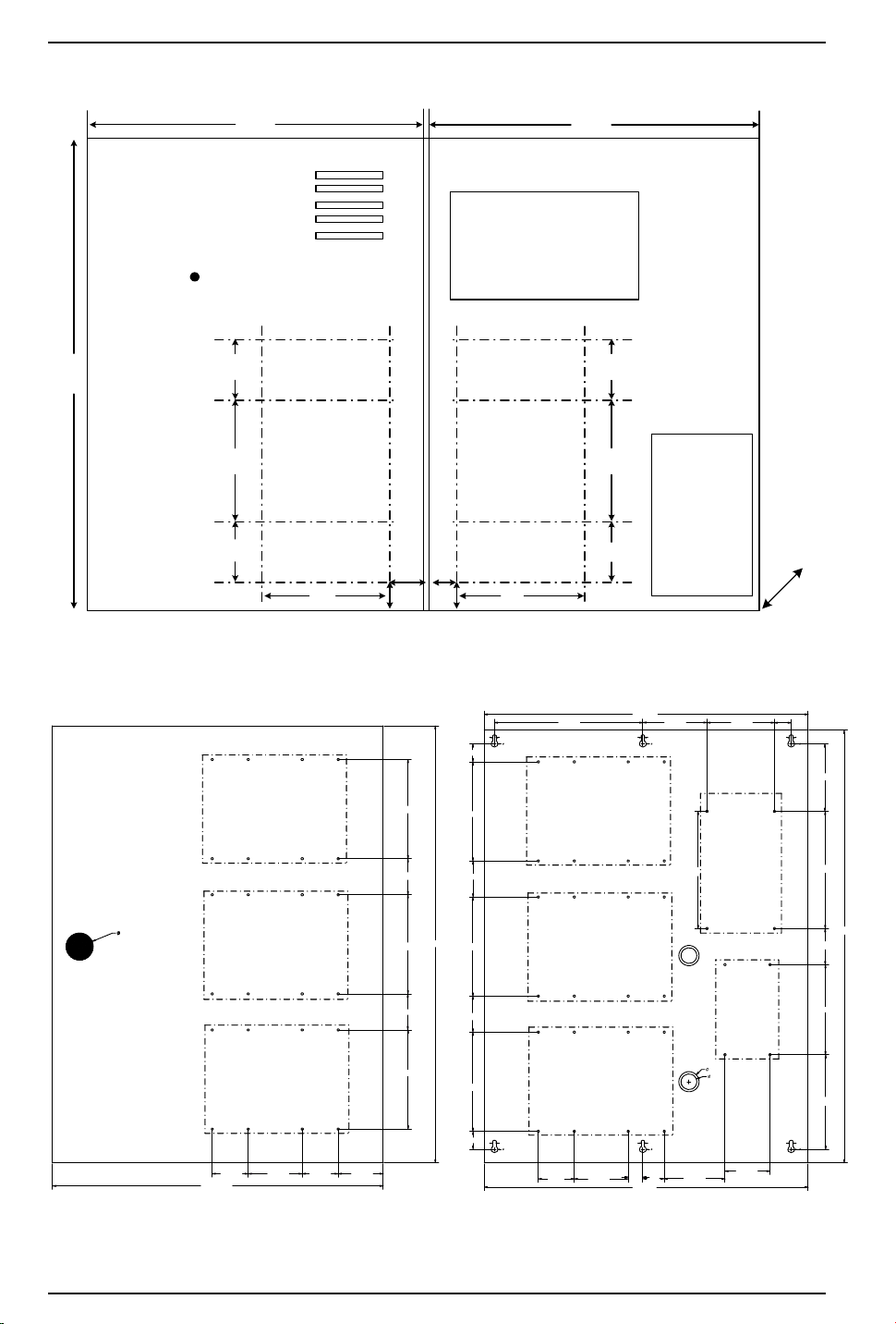
Most modules are 6 x 8 inches in size, with mounting holes along the long edge. Up to two (2) units can be
mounted in a single LNL-CTX enclosure. The LNL-CTX-6 allows for up to six (6) modules.
revision 7 — 29
Page 30
Hardware Installation Guidelines
12.5" 12.5"
15.5"
Optional
Battery
Power Supply
Piano Hinge
Hardware
Standoffs
3.00" 2.00"2.00"
Hardware
Standoffs
3.00" 2.00"2.00"
0.875"1.25"
1.75"
1.75"
5.50"5.50"
D
e
p
t
h
=
4
.
5
"
Cabinet Lock
1.5000
18.3750
2.0000 2.0000 2.50003.0000
5.5000
2.0000
5.5000
24.2500
2.0000
5.5000
18.0000
8.2500
3.5625 3.7500
0.9375
0.18690.1869
0.3750
0.1869
0.3750
1.0000
5.5000
2.0000
5.5000
2.0000
5.5000
1.0000
0.1869
0.3750
0.1869
0.3750
2.000 3.0000
18.0000
3.3750
2.5000
0.1869
0.3750
5.2500
5.0000
24.0000
2.0000
1.1250
0.8750
6.5000
3.7500
6.5000
Power Supply
Main Fuse
1.1875
0.8125
0.3750
LNL-CTX
LNL-CTX-6
30 — revision 7
Page 31
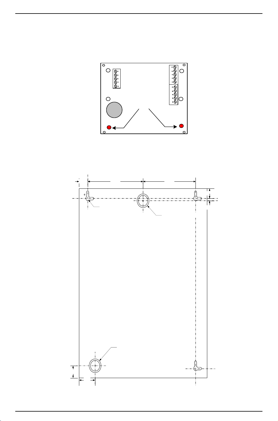
Hardware Installation Guide
DO NOT DISPOSE
[QTY 2]
INSERT
STANDOFFS
HERE
Backbox Mounti ng Hole Configurat ion
0.8125
1.0"
1.50"
3/4" and 1" Knock Outs
5.1875" 4.8125"
0.875"
0.125"
3/4" and 1" Knock Outs
0.375" Cl earance Hole
0.1875" Sl ots nominal
For smaller modules, only four of the mounting holes are used, the last two holes need support standoffs
which come installed from the factory. The exception is the single reader interface module — up to eight (8)
units can be mounted in any standard 2-gang or 3-gang junction enclosure.
The standoffs for the hardware come in a separate package. The diagram below illustrates positioning.
LNL-CTX knockout diagram
revision 7 — 31
Page 32
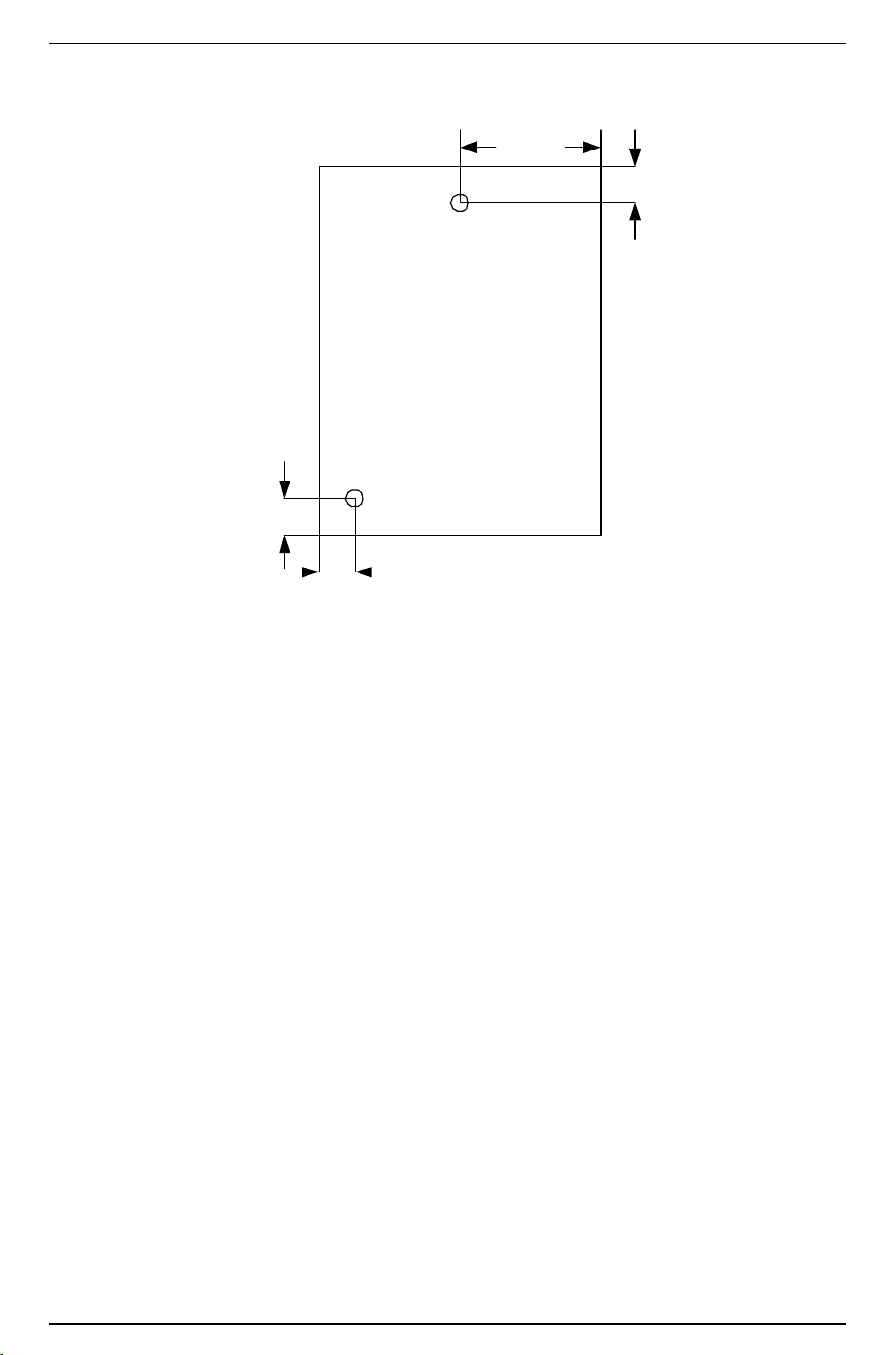
Hardware Installation Guidelines
1/2" and 3/4 knockout location
drawing
1.5"
1.0"
6.0"
1.0"
LNL-CTX knockout location drawing
2.2.1 LNL-AL400ULX Installation
The LNL-AL400ULX should be installed in accordance with article 760 of the National Electrical Code and
NFPA70 as well as all applicable local codes.
1. Mount the enclosure in desired location.
32 — revision 7
Page 33
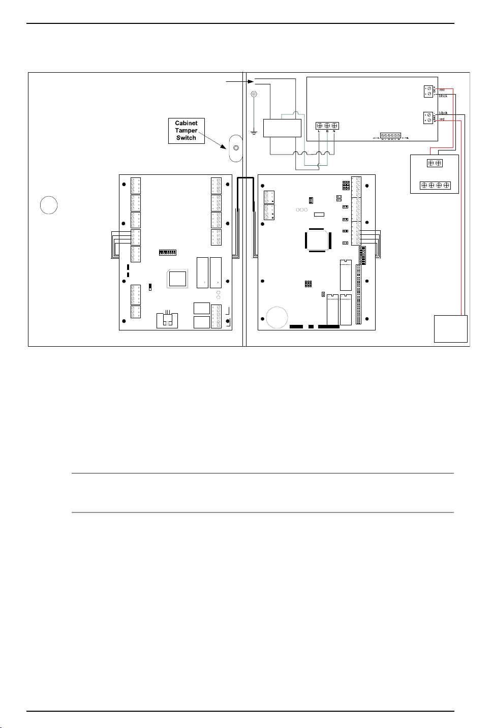
Hardware Installation Guide
Input 120 VAC, 60 Hz, 1.45 amp.
blue
green
brown
DC Output,
Battery & AC
Supervision
Circuit
(power limited)
To Battery
in CTX
+ INPUT ---
+ OUT2--- + OUT1---
2. Connect unswitched AC power (120 VAC/60 Hz) to terminals marked L, G, N, dedicated to the Burglar
Alarm/Access Control Subsystem.
3. Secure the green wire lead to earth ground. Use 18 AWG or larger for all power connections (Battery,
DC output).
4. Keep power limited wiring separate from non-power limited wiring (115 VAC/60 Hz Input, Battery
wires). Minimum 0.25 inch spacing must be provided between power wires.
5. Connect devices to be powered to terminals marked -out1+; -out2+ on the two-output distribution
board. Each output is rated to 2 A maximum.
Note: It is important to measure output voltage before connecting devices. This helps avoid potential
damage.
6. For UL Access Control applications, batteries are required. When batteries are not used, a loss of AC
will result in the loss of output voltage. When using stand-by batteries, they must be lead acid or gel
type. Connect battery to terminals marked + BAT – (battery leads included).
7. Connect appropriate trouble reporting devices to AC Fail and Low Battery supervisory relay outputs
marked NC, C, NO. Use 22 AWG to 18 AWG for AC Fail and Low Battery reporting. AC Failure will
will report in 2 minutes; 2 hours if jumper is cut. For a six-hour delay on reporting, cut resistor R1.
revision 7 — 33
Page 34
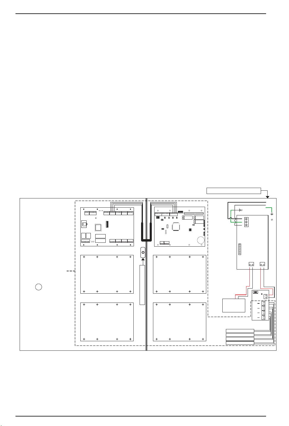
Hardware Installation Guidelines
LENEL Hardware
LENEL Hardware
LENEL Hardware
LENEL Hardware
AL1012ULXB
L G N
black
red
black
red
Input 115 VAC, 60Hz, 1.9 amp.
To Battery
in LNL-CTX
Main Fuse
1P, 2P, 3P, and 4P = Fused Outputs
F1
F2
F3
F4
ON - OFF
+ BAT--
ACFAILBATFAIL
NC C NO NC C NO
+ DC --
-- +
4 4
P N
3 3
P N
2 2
P N
1 1
P N
Input
PD4A
1N, 2N, 3N, and 4N = Common Outputs
Output Circuit 1
Output Circuit 2
Output Circuit 3
Output Circuit 4
Neutral - White
Ground - Green
Hot - Black
white
green
black
Cabinet Tamper Switch
Power
Limited
Devices
LENEL
Hardware
LENEL
Hardware
LNL-AL600ULX-4CB6
Enclosure Dimensions:
24"H x 18"W x 4.5"D
Unit includes Cabinet,
Cabinet Tamper Switch,
Power Supply, Power
Distribution Circuit, Battery
Leads, Lenel access
hardware mounts/screws,
and Lock.
CAUTION:
De-energize
unit prior to
servicing. So
not expose to
rain or
moisture.
Battery & AC
Supervision
Circuit
(power limited)
8. Wire routing note: UL two panel installation instructions for LNL-CTX enclosures
To install multiple Lenel hardware panels into a single enclosure, the following guidelines must be used
for certified UL installations.
• All wire connections that cross over the hinge side of the door must be wire wrapped or tie wrapped
together.
• All wire must be routed behind the hardware panel so that the wires are secure from movement
when opening and closing the door.
• All connections for the lock side of the enclosure must come from behind the Lenel hardware
devices.
2.2.2 LNL-AL600ULX-4CB6 Installation
The LNL-AL600ULX-4CB6 should be installed in accordance with article 760 of the National Electrical
Code of NFPA70 as we as all applicable local codes. If you are located in Canada, refer to the Canadian
Electrical Code.
1. Mount the enclosure in desired location.
2. The power supply is pre-wired to the ground (chassis). Connect main incoming ground to the provided
green grounding conductor lead. Connect unswitched AC circuit (115 VAC/60 Hz) dedicated to the
Burglar Alarm/Access Control Subsystem to terminals marked L, G, N.
3. Keep power limited wiring separate from non-power limited wiring (115 VAC/60 Hz Input, Battery
wires). Minimum 0.25 inch spacing must be provided between power wires.
4. Connect devices to be powered to terminals marked (1P-1N, 2P-2N, 3P-3N, 4P-4N) and distribute
evenly. Each output is rated at 1.5 amps max.
34 — revision 7
Page 35
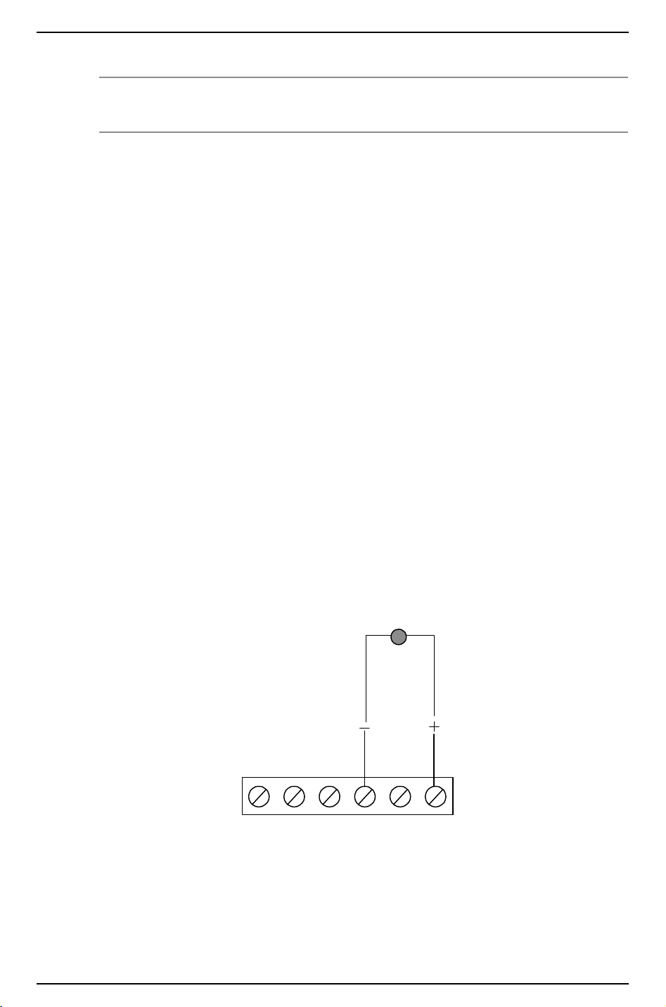
Hardware Installation Guide
NO CNC NC AC FAILBAT FAIL NOC
LED
Note: It is important to measure output voltage before connecting devices. This helps avoid potential
damage. Use 18 AWG or larger wire for all power connections (battery, DC outputs).
For UL Access Control applications, batteries are required. When batteries are not used, a loss of AC
will result in the loss of output voltage. When the use of stand-by batteries is desired, they must be lead
acid or gel type. Connect battery to terminals marked + BAT – (battery leads included).
5. Connect appropriate trouble reporting device to the Battery Fail and AC Fail supervisory relay outputs
marked NC, C, NO. Use 22 AWG or 18 AWG for AC Fail/Battery Fail reporting. AC Failure will report
in 2 minutes; 2 hours if jumper is cut. For a six-hour delay on reporting, cut resistor RL1.
6. Connect cabinet tamper switch to cabinet tamper circuit on the Lenel access hardware.
7. Wire routing note: UL six panel installation instructions for LNL-CTX enclosures
To install multiple Lenel hardware panels into a single enclosure, the following guidelines must be used
for certified UL installations.
• All wire connections that cross over the hinged side of the door must be wire wrapped or tie
wrapped together.
• All wire must be routed behind the hardware panels so that the wires are secured from movement
when opening and closing the door.
• All connections from the lock side of the enclosure must come from the Lenel hardware devices.
2.2.3 AC Indicator
UL 294 installations require an external AC indicator.
1. Locate the “AC FAIL” terminals.
2. Wire an LED indicator according to the following diagram.
AC indicator wiring
3. Install the indicator on the outside of the enclosure. It should be installed using the designated AC
knockout.
revision 7 — 35
Page 36

Hardware Installation Guidelines
2.2.4 Cabinet Tamper
Cabinet tamper for all enclosures must be connected and programmed for UL installations.
2.3 Ground Wiring
Each hardware product must be grounded to provide ESD protection, personnel safety, and signal reference
for devices which communicate with each other. Grounding provides a good shield against external
transients. See the installation manuals for the grounding point of each product.
There are three types of circuit grounds in systems using hardware products:
• DC negative
• RS-485 signal ground
• Safety ground
2.3.1 DC Negative
The DC ground provides signal reference for devices to communicate. It is the DC return from the power
supply.
2.3.2 RS-485 Signal Ground (SG)
The RS-485 signal ground is connected to the DC ground internal to a device through a current limiting
resistor. It provides a signal reference for the RS-485 interface.
2.3.3 Grounding System
A grounding system can be viewed as two subsystems: the DC system and the ground system. The DC
system consists of all interconnected power supply returns, DC distribution wiring, and load devices. The
principal function of the DC system is to provide signal reference for communication. The ground system
consists of all chassis grounds for power supplies and other devices, safety grounds, and AC grounds.
Ground connection should be made to avoid ground loop problems.
Ideally, there should be ONLY ONE ground return point in a power supply system.
2.3.4 Safety Ground
Safety ground (copper wire of 16 AWG minimum) is part of the AC power system. To avoid ground loop
current, there must be NOT more than one point at which the safety ground connects to the DC ground.
The RS-485 signal ground must be isolated from the safety ground. This means that the RS-485 cable shield
must be insulated so that it will NOT accidentally short circuit to the conduit in instances where the conduit
is connected to the safety ground.
The National Electrical Code and other safety regulations require that all equipment chassis and or
enclosures be grounded in order to prevent shock hazards. Each device must have a green wire safety
ground. The function of the green wire safety ground is to provide a redundant path for fault currents and to
insure that the circuit breaker will open in the event of a fault. In addition, grounding the enclosure provides
a path for ESD dissipation, thus protecting sensitive electronic devices.
36 — revision 7
Page 37
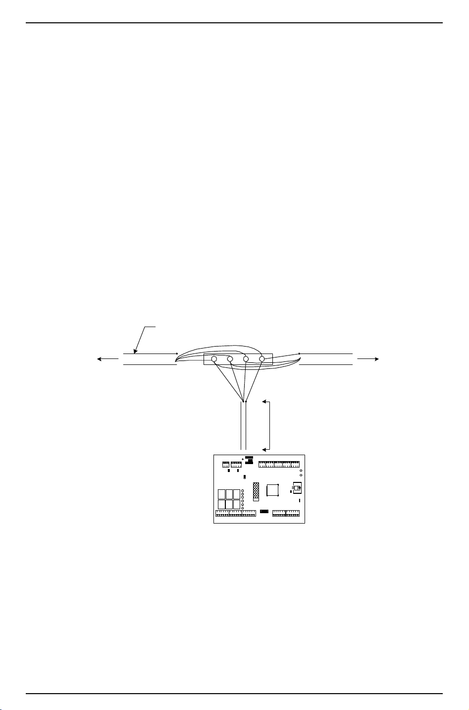
Hardware Installation Guide
KEEP DOWN LEAD SHORT
(10 FEET MAX.)
TO NE XT UNIT
OR TERMINATOR
TO PREVIOUS UNIT
OR TERMINATOR
RS-485 CABLE, 100 Ohm IMPEDANCE
BELDEN 984 2 OR EQUIVALENT
Reader Interface Module
2.4 Alarm Input Wiring
All alarm inputs require twisted pair wires. An end-of-line (EOL) resistor terminator is required for each
supervised alarm input. Both supervised and unsupervised alarm inputs can support single or multiple
contacts per loop. Connect normally closed (NC) contacts in series and normally open (NO) contacts in
parallel.
2.5 RS-485 Communication Wiring
Proper wiring for RS-485 communication interfaces is critical for successful system turn-up and operation.
The following guidelines apply for all RS-485 wiring.
1. Use low capacitance shielded cable with 2 twisted pairs, characteristic impedance 120 ohms (Belden
9842 or equivalent) for the main RS-485 run.
2. Keep the main run maximum end-to-end distance below 4000 feet.
3. Use daisy chain configuration, NOT star configuration, to connect devices.
4. Use shielded 24 AWG cable with 2 twisted pair (Belden 9502 or equivalent.) for down leads (drops or
stubs).
5. Keep down leads as short as possible (no longer than 10 feet).
6. Terminate cables at both ends with RS-485 terminators (hardware has on-board terminators for RS-485
termination).
7. Always use the signal ground (SG) connection. Carefully insulate the SG wire for a reliable installation.
Use 24 GA plastic sleeving over the SG wire when terminating the cable to the 5-position insulation
displacement mating connector.
Each RS-485 communication line can have any number of DEPENDENT devices, but must have only one
MASTER device. The transmit lines of the MASTER device are connected to the receive lines of the
revision 7 — 37
Page 38
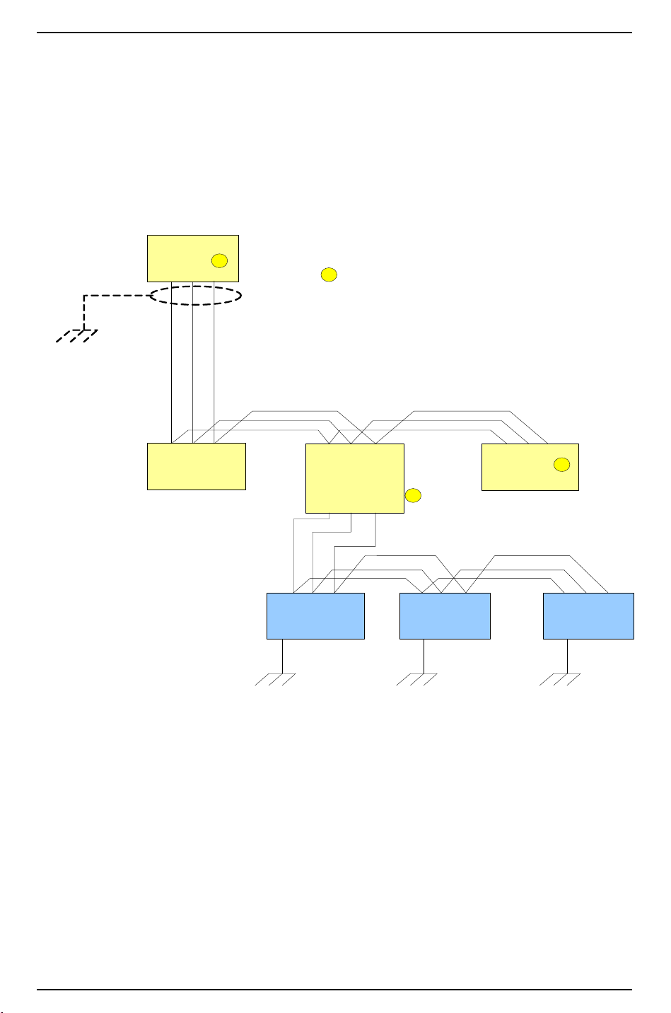
Hardware Installation Guidelines
RS-485 Multi-drop Wiring and EOL Termination
ISC
T+ T- SG
Earth Ground,
one point only
per ISC
Shiel d
PVC Cover Wire
PVC Cover Wire
PVC Cover Wire/or Drain
Wire
T+ T- SG
Dual Reader
Inte rface
T+ T- SG
Biometric Reader
Gatew ay
T+ T- SG
T+ T- SG
Dual Reader
Inte rface
T
T
T
= On Board Termination
T+ T- SG
Biometric Reader
T+ T- SG
Biometric Reader
T+ T- SG
Biometric Reader
T
Enclosure Ground Enclosure Ground
Enclosure Ground
Downstream ports
2 & 3 typical
DEPENDENT devices and the receive lines of the MASTER device are connected to the transmit lines of
the DEPENDENT devices. Observe the + and the - of each pair (NOTE: only applies to 4-wire RS-485
wiring).
Refer to the following diagrams for RS-485 Signal Ground and Termination.
RS-485 Multi-drop Wiring and EOL Termination
38 — revision 7
Page 39
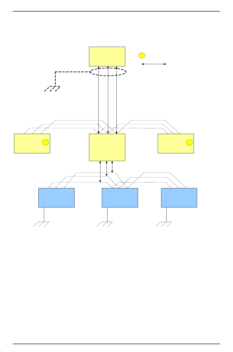
Hardware Installation Guide
T+ T- SG
Biometric Reader
T+ T- SG
Biometric Reader
T+ T- SG
Biometric Reader
ISC
T+ T- SG
Earth Ground, one point only
per ISC
Shield
PVC Cover Wire
PVC Cover Wire
PVC Cover Wire/or Drain
Wi re
T+ T- SG
Dual Reader
Interface
T+ T- SG
Biometric Reader
Gatew ay
T+ T- SG
T+ T- SG
Dual Reader
Inte rface
T
T
T
= On Board Termination
Enclosure Ground Enclosure Ground Enclosure Ground
RS-485 Multi-drop Wiring and EOL Termination
ISC and Biometric Gateway Mid RS-485
= Indicates RS-485 in and out
or less than 10 foot drop
Downstream ports
2 & 3 typical
RS-485 Multi-drop Wiring and EOL Termination: ISC and LNL-500B
revision 7 — 39
Page 40
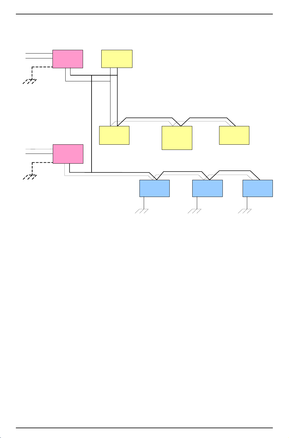
Hardware Installation Guidelines
Multiple Power Supplies on Single ISC
ISC
DC+ DC-
Earth Ground
PVC Cover Wire RED
PVC Cover Wire BLACK
DC+ DC-
Dual Reader
Interfa ce
DC+ DC-
Biometric
Reader Gateway
DC+ DC-
Dual Reader
Inte rface
DC+ DC-
Biometric
Reader
DC+ DC-
Biometric
Reader
DC+ DCBiometric
Reader
Chassis Ground Chassis Ground
Chassis Ground
12 VDC
Power Su pply
DC+ DC-
Grou nd -
Gree n
Line - Black
Neutral - White
110 VAC Source
12 VDC
Power Supply
DC+ DC-
Grou nd -
Gree n
Line - Black
Neutral - White
110 VAC Source
Must connect
DC- when using
multiple power
supplies on a
Sin gle ISC
Multiple Power Supplies on a Single ISC
2.6 RS-232 Communication Wiring
Observe the distance limitation or use suitable cable if the distance is greater than 50 feet. Remember to
strap the control lines (RTS, CTS, etc.) if required.
2.7 Weatherproofing
The circuit board compartment of small readers should be sealed to protect from harsh environment.
Be sure to clean the read head(s).
The leading cause of accelerated readhead wear is contamination in the read head slot. To maximize the life
of the read head, it is important to clean the reader periodically to remove any contamination. The frequency
depends on the environment in which the reader is located. Indoor readers in controlled environments will
need to be cleaned much less often than an outdoor reader exposed to airborne dirt and debris. Dirt and
debris are also transferred from cardholder cards that have been contaminated with sticky substances. Read
head cleaning cards are available to clean the readers.
For heavy traffic areas, extended life read heads are also available from the factory at the time of order
which will extend the read head life up to 1 million card swipes. For heavy traffic, outdoor readers should be
cleaned at least once per month. A good indication as to how often a reader needs to be cleaned is when
using a cleaning card, if the card has no visible signs of contamination, the reader could be serviced less
40 — revision 7
Page 41
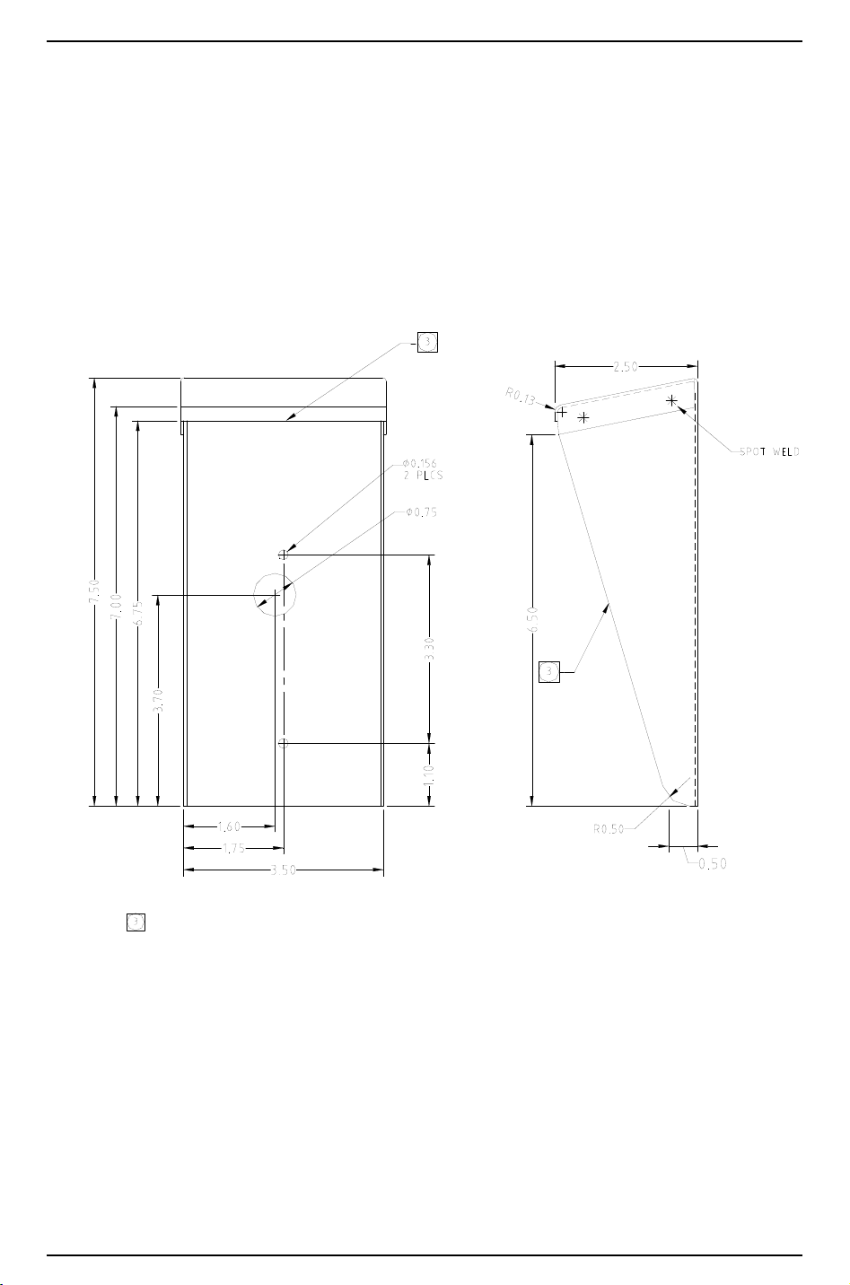
Hardware Installation Guide
EXPOSED EDGES ( FRONT AND TOP) MUST BE ROUNDED/SMOOTHED, RADIUS 0 .01 5 T YP.
2. F INISH: CLEAN AND DEBUR. SAND TO BREAK ALL EDGES.
BRUSH F INISH TOP/ SIDE SURF ACES (200 GRIT ). GRAIN VERTICAL.
1. M ATERI AL: ST AINL ESS STEEL, TYPE 3 04-2B, 18G A
NOTES: UNLESS O THERWISE SPECIF IED
often. Another indication is if the card reader, starts to give invalid card reads, the reader may need to be
serviced more often. A read head that is starting to fail due to exceeding the maximum number could cause
this or card reads on the read head (std. 600,000 or extended 1 million).
• Weather Shield Option even though the Magnetic swipe card readers are fully weatherized, there are
still times when the card reader may need more protection from the environment. If a reader has been
installed at a remote parking lot or on a build with no overhang to prevent rain, ice or snow from
building up in the reader throat, you may want to install the weather shield (LNL-WS10). This weather
shield can be used with all LNL-2005W, 2010W, and 2020W readers.
Weather Shield – part #LNL-WS10
2.8 Relay Contact Protection
The relays used by OnGuard hardware products have a contact life in excess of 500,000 operations at full
rating. Lighter loads, and appropriate contact protection, extend relay life.
revision 7 — 41
Page 42

Hardware Installation Guidelines
DC SOURCE
AC SOURCE
NC
C
NO
NC
C
NO
FUSE
+
-
LOAD
LOAD
MOV
FUSE
2.8.1 DC Inductive Load
Contacts for DC inductive loads can be effectively protected using clamp diodes. Select diodes with reverse
breakdown voltage 10 times the circuit voltage.
2.8.2 AC Inductive Loads
Contacts for AC inductive loads can be protected using metal-oxide varistors (MOVs.) MOVs are effective
when the load voltage is 100V to 200V. (MOVs are also suitable for DC operation.)
MOVs must be installed as close to the load as possible (within a few inches) to be effective. Mounted in
this fashion, MOVs can also reduce the effects of EMI on sensitive electronic circuits.
42 — revision 7
Page 43

Hardware Installation Guide
3 System Turn-Up Considerations
A system should never be wired up and powered up all at once. For successful system turn-up, the following
step-by-step procedures should be performed.
1. Make sure that no power is applied to any system device.
2. Check all wiring and device switch settings.
3. Disconnect all devices from the RS-485 communication line.
4. Power up the controller. (Check voltage requirement first.)
5. Configure the controller, and verify that it is working properly.
6. Connect one port of the RS-485 communication line to the multiplexer.
7. Power up a DEPENDENT device, and verify that it passes its own power-up self-test. (Check voltage
requirement first.)
8. Check for ground fault between the DEPENDENT device and the RS-485 communication line. If
applicable, find the fault and clear it.
9. Connect the DEPENDENT device to the RS-485 line and bring in on-line.
10. Verify all functions of the DEPENDENT device.
11. Verify the RS-485 line voltage in reference to the signal ground (SG.)
12. For each additional DEPENDENT device, repeat steps 7 through 11.
13. Verify the RS-485 line voltage for the controller, and mark the readings on the inside of the controller
panel for future reference.
System Testing
For UL1076 compliance, a general system test should be performed at least once per year.
3.1 Device Configuration Checks
Common device configuration problems include mismatched baud rates and incorrect device addresses. No
two devices on the same RS-485 line should have the same device address. Check all switch settings before
attempting to bring the device on-line.
System programming must include the order of priority signals described below:
1. Hold-up or panic alarm or duress.
2. Burglar alarm.
3. Burglar-alarm supervision.
4. Industrial supervision where a risk of injury to persons, or damage or destruction of property will not be
involved.
5. Other supervisory services.
Items (1) and (2) may have equal priority. Items (4) and (5) may have equal priority.
revision 7 — 43
Page 44

Hardware Installation Guidelines
3.2 Ground Potential Difference Checks Before Connecting
Before a device can be connected to the RS-485 communication line, it must be checked for ground fault.
Uncorrected ground fault can damage all devices connected to the RS-485 communication line.
To check if there is ground fault for a new unit, follow the steps below.
1. Apply power to all devices already successfully connected to the RS-485 line.
2. Power up the new unit, but DO NOT connect it to the RS-485 line.
3. Connect the signal ground (SG) of the RS-485 line through a 10K limiting resistor.
4. Measure the AC and DC voltage across the resistor. There should NOT be more than 1 volt across the
resistor. Otherwise find and clear the fault.
5. Connect the new unit to the RS-485 line if no ground fault is found.
44 — revision 7
Page 45

Hardware Installation Guide
4 Maintenance
Firmware download is only supported for models and versions of Lenel hardware.
Firmware Download Capabilities (for current version of OnGuard)
Module Is firmware
download
supported?
Controller (LNL-500,
1000, 2000)
Controller (LNL-4420,
3300, 2220, 2210)
Input Control Module
(LNL-1100) Series 2
Output Control Module
(LNL-1200) Series 2
Single Reader Interface
Module (LNL-1300)
Series 2
Single Door IP
Interface Module
(LNL-1300e)
Dual Reader Interface
Module (LNL-1320)
Series 2
Yes Firmware version 3.1xx or later is recommended
Yes Firmware version is 1.2xx or later.
Yes Firmware version is 1.3xx or later.
Yes Firmware version is 1.3xx or later.
No Currently, firmware version 1.5xx or later.
Yes Firmware version 1.6xx or later is recommended.
Yes Firmware version is 1.5xx or later, and the board is rev. B.
Requirements
Command Keypad
(LNL-CK)
Gateways (LNL-500B,
500W)
The most current version of the firmware is shipped with your OnGuard software and was installed during
the initial software installation. Each subsequent software release you receive will also include the most
current version of the firmware.
No Firmware version 1.63 (factory firmware upgrades only).
This firmware cannot be upgraded in the field.
Yes These have other firmware requirements, depending on their
downstream devices.
• For Bioscrypt V-Series readers, the LNL-500B requires
firmware version 1.26.
• For HandKey readers, the LNL-500B requires firmware
version 1.25.
• To use wireless readers, the LNL-500W requires
firmware version 1.10.
revision 7 — 45
Page 46

Hardware Installation Guidelines
4.1 Firmware Updates
Do the following to update the firmware on your system. You must have the “ADMIN” permission level.
1. Install the new version of the OnGuard software.
2. In the Main Alarm Monitor window of the Alarm Monitoring module, right-click on the name of an
access panel.
3. Select the Download Firmware choice from the popup menu
4. OnGuard will initiate the firmware update then perform a full download to the access panel and to all
devices connected to it.
You must update each access panel in the system. Although it is not necessary to shutdown the application to
perform the updates, note that the selected access panel is placed in a degraded off-line mode during the
process. During this process, the readers connected to the panel are put into their off-line mode (“facility
code only,” “locked,” etc.), which is configured on the Reader form of the System Administration module. It
is strongly recommended that you perform the update on the panel during a time when no one will be
accessing it.
Firmware can be simultaneously downloaded to multiple panels at once. However, it is recommended to do
so one at a time to prevent any problems from occurring until you become familiar with the impact on
system performance.
4.2 AES/Extended Firmware
The ISC (LNL-500, 1000, and 2000) supports encryption and asset management with use of AES/Extended
firmware. The controller must have a 256 KB chip.
If you wish to use this feature and have a controller with a 128 KB chip, it must be upgraded. Typically, this
upgrade would be required for the LNL-500 serial number 6352 or lower or the LNL-1000 serial number
12862 or lower.
Encryption is controlled by a DIP switch setting. Turn DIP switch 8 ON to enhance security. When a host
system attempts to communicate with an encryption-enabled controller, a proper master key is required.
Note: The controller only reads DIP switch settings when it is powered up. If DIP switch settings are
changed, the controller must go through a power cycle before the changes are seen.
Asset management can be done with any standard Wiegand output asset reader. Assets are stored in the
controller and linked to cardholders.
46 — revision 7
Page 47

Hardware Installation Guide
5 UL/ULC Certified Installations
The system is to be installed within a protected premise. In a subassembly, the operating temperature range
must be 0° to 49°C; the humidity range must be 0 to 85% RH.
This system must be installed in accordance with the National Electrical Code (NFPA 70), and the local
authority having jurisdiction. If you are located in Canada, please refer to the Canadian Electrical Code.
For UL Installations, the central supervisory station equipment must be UL Listed to:
• Information Technology Equipment, UL/CSA 60950
For UL Installations, use UL Listed information technology equipment. The computer minimum platform
requirements are as follows.
• Intel Pentium 4 dual core processor
• 3.4 GHz clock speed
•2 GB RAM
• 6 GB of hard drive space for OnGuard
• DVD-ROM drive
• One (1) USB port
• Operating systems:
- Windows Server 2012 R2
- Windows Server 2012
- Windows 7
- Windows 8/Windows 8.1
• Microsoft SQL Server 2014 (32 and 64-bit), SQL 2014 Express, Microsoft SQL Server 2012 (32 and
64-bit), or SQL 2012 Express
• Access control/proprietary burglary systems:
- OnGuard 7.0 (7.0.000) using Hardware Installation Guide revision 4.0.###
- OnGuard 7.1 (7.1.000) using Hardware Installation Guide revision 5.0.###
- OnGuard 7.2 (7.2.000) using Hardware Installation Guide revision 6.0.###
- OnGuard 7.3 (7.3.000) using Hardware Installation Guide revision 7.0.###
• NEC ExpressCluster X R3 Fault Tolerant software
The following devices must be incorporated into the system:
• Supply line transient protection complying with the Standard for Transient Voltage Surge Suppressors,
UL 1449, with a maximum marked rating of 330 V.
• Signal line transient protection complying with the Standard for Protectors for Data Communications
and Fire Alarm Circuits, UL 497B, with a maximum marked rating of 50 V.
• Signal line transient protection complying with the Standard for Protectors in Telecommunication
Networks, CAN/CSA-C22.2 No. 226-92.
Equipment must be installed in a temperature controlled environment, maintained between 13 - 35°C (55 95°F) by the HVAC system. 24 hours of standby must be provided for the HVAC system.
HVAC rated modules were not evaluated by UL for Lenel OnGuard UL1076 product Listing.
revision 7 — 47
Page 48

Hardware Installation Guidelines
In addition to the main power supply and secondary power supply that are required to be provided at the
central supervisory station, the system must be provided with an uninterruptable power supply (UPS) with
sufficient capacity to operate the computer equipment for a minimum of 15 minutes. If more than 15 minutes
is required for the secondary power supply to supply the UPS input power, the UPS must be capable of
providing input power for at least that amount of time. A means for disconnecting the input to the UPS while
maintaining continuity of power to the automation system must be provided, in order to perform
maintenance and repair service.
The UPS must comply with the Standard for Uninterruptable Power Supply Equipment, UL1778/
CSA-C22.2 No. 107.3, or the Standard for Fire Protective Signaling Devices, UL1481/ULC-S527.
Be sure to use the recommended cabling, which is the shielded wiring required for use on all modules.
Communication circuits and network components connected to the telecommunications network shall be
protected by secondary protectors for communication circuits. These protectors shall comply with the
Standard for Secondary Protectors or Communications Circuits, UL 497A. These protectors shall be used
only in the protected side of the telecommunications network.
A metal conduit must be used when connecting all UL enclosures. This is required for all UL installations.
Do not exceed 1000 receiver accounts for UL.
All receiving equipment shall be completely duplicated with provision for switchover to the backup system
within 30 seconds. The backup system shall be fully operational within 6 minutes of the loss of the primary
system. (This allows 30 seconds for the backup system to be fully energized and connected to the necessary
communication lines and other devices, followed by 5-1/2 minutes for the system to boot up, conduct
memory tests, file system check, security verifications, and prepare for full system operation). The backup
computer must have the capabilities of the primary, such as memory, speed, and the like.
Failure of the main computer system, hard disk, and alarm monitor must be programmed to switchover to
the backup system, and indicate an audible, or obvious visual indication.
A fault tolerant system may be used in lieu of complete duplication of the system if every component in the
fault tolerant system, including the software and power supply, is duplicated.
All OnGuard system solutions that are to be UL1076 compliant systems must also meet the requirements
specified in Section 25A of the UL1076 (Proprietary Burglar Alarm Units and Systems Standard for Safety).
This requirement outlines the need for host monitoring redundancy. Host monitoring redundancy can be
accomplished in many ways, but the standard is clear as to receiving equipment methods, recovery time,
surge suppression and system configurations. Contact Lenel if configuration assistance is required.
All inputs must be supervised for UL1076 installations.
Priority features (alarm, loss of line voltage, opens, shorts, etc.) must be programmed for an audio and a
visual indication at the central supervisory station equipment, and to create a printout. The condition must be
recorded. This indication shall not be silenced without acknowledgement.
Bypass of protective features, such as auto-bypass for forced arm, must not be programmed for UL.
If a modem or Ethernet is used as a method of communication, the connection must be maintained
continuously.
Use Marking — Commercial, Proprietary, Multiplex, Encrypted Line Security Burglar Alarm System
Control Unit and Access Control Unit.
48 — revision 7
Page 49

Hardware Installation Guide
Lenel AES Firmware v1.02 is “extended” firmware that is embedded (installed) in conjunction with
Intelligent System Controllers (ISC), models LNL-500, LNL-1000, LNL-2000 (firmware version 3.085 or
later), models LNL-2220, LNL-3300, LNL-4420 (firmware version 1.068 or later) for suitability as
“Encrypted Line Security Equipment.”
Network addressing of devices shall not make use of public domain name servers.
Panic hardware must be UL 305/ULC-S132 Listed.
5.1 Power
The standby power system for the HVAC system may be supplied by an engine driven generator alone. Use
of a standby battery is not required.
All external interconnecting power sources must be UL/ULC Listed access control/proprietary burglary
power limited power supplies. AC supply lines shall not be routed in the same conduit or harness as low
voltage lines.
5.1.1 UL/ULC Certified Power Supplies
For the UL certification, the power supply that must be used is the LNL-AL400ULX or
LNL-AL600ULX-4CB6 with additional hardware mounted in LNL-CTX or LNL-CTX-6 enclosures. Other
power supplies will be certified for use at a future date.
For the ULC Certification, hardware must be mounted in LNL-CTX or LNL-CTX-6 enclosures. All power
supplies must be UL, ULC, or cUL Listed for security applications, and power-limited.
Output 4 hr. of Stand-by &
LNL-AL400ULX12 VDC/
40 AH Battery
LNL-AL600U
LX-4CB6
12 VDC/
40 AH Battery
5 minutes of Alarm
Stand-by = 4.0 amps
Alarm = 4.0 amps
Stand-by = 6.0 amps
Alarm = 6.0 amps
24 hr. of Stand-by
& 5 Minutes of
Alarm
Stand-by = 1.0 amp
Alarm = 4.0 amps
Stand-by = 1.0 amp
Alarm = 6.0 amps
60 hr. of Stand-by
& 5 Minutes of
Alarm
Stand-by = 300 mA
Alarm = 4.0 amps
Stand-by = 300 mA
Alarm = 6.0 amps
5.2 Typical Combinations for UL Installations
The following combinations must be used in a UL type installation with OnGuard software versions 7.0.xxx,
7.1.xxx, 7.2.xxx, or 7.3.xxx which are approved for use. For UL certification, a UL Listed power supply,
either LNL-AL400ULX or LNL-AL600ULX-4CB6 with additional hardware mounted in LNL-CTX or
LNL-CTX-6 enclosures, must be used.
Multiple combinations of Lenel access hardware can be used within the UL approved power supply and
enclosure.
revision 7 — 49
Page 50

Hardware Installation Guidelines
Intelligent System Controller Combinations
Any individual board would be supported (LNL-500, LNL-1000, LNL-2000, LNL-3300, LNL-2210,
LNL-2220, LNL-4420) as well as any combination of the following boards within a single enclosure.
1. LNL-500, 1000, 2000, 3300, 2210, 2220 or 4420 Intelligent System Controllers
LNL-1001-MK or LNL-1003-MK or LNL-1007MK (2000 only) Memory Expansion Modules
LNL-1100 Alarm Input Control Module
2. LNL-500, 1000, 2000, 3300, 2210, 2220 or 4420 Intelligent System Controllers
LNL-1001-MK or LNL-1003-MK or LNL-1007MK (2000 only) Memory Expansion Modules
LNL-1200 Alarm Output Control Module
3. LNL-500, 1000, 2000, 3300, 2210, 2220 or 4420 Intelligent System Controllers
LNL-1001-MK or LNL-1003-MK or LNL-1007MK (2000 only) Memory Expansion Modules
LNL-1300 Single Reader Interface Module (Up to four (4) units)
4. LNL-500, 1000, 2000, 3300, 2210, 2220 or 4420 Intelligent System Controllers
LNL-1001-MK or LNL-1003-MK or LNL-1007MK (2000 only) Memory Expansion Modules
LNL-1320 Dual Reader Interface Module
5. LNL-500, 1000, 2000, 3300, 2210, 2220 or 4420 Intelligent System Controllers
LNL-1001-MK or LNL-1003-MK or LNL-1007MK (2000 only) Memory Expansion Modules
LNL-8000 Star Multiplexer
6. LNL-500, 1000, 2000, 3300, 2210, 2220 or 4420 Intelligent System Controllers
LNL-1001-MK or LNL-1003-MK or LNL-1007MK (2000 only) Memory Expansion Modules
LNL-4000 Multiplexer (Up to two (2) units)
7. LNL-500, 1000, 2000, 3300, 2210, 2220 or 4420 Intelligent System Controllers
LNL-1001-MK or LNL-1003-MK or LNL-1007MK (2000 only) Memory Expansion Modules
LNL-500B or BI Biometric Reader Interface Gateway
8. HID Edge or HID Edge Plus Controller
Reader Interface Modules and Gateways Combinations
Any individual board would be supported (LNL-1300 or LNL-1320) as well as any combination of the
following boards within a single LNL-CTX enclosure.
1. LNL-1320 Dual Reader Interface Module (up to two (2) units)
2. LNL-1300 Single Reader Interface Module (up to eight (8) units)
3. LNL-500B or BI Biometric Reader Interface Gateway (up to two (2) units)
4. LNL-2210 Intelligent Single Door Controller (up to two (2) Units)
5. LNL-1300e Single Door IP Interface Module (up to two (2) Units)
6. LNL-1320-U Dual Door Controller (up to two (2) units)
7. LNL-1300-U Single Door Controller (up to eight (8) units)
Any individual board would be supported (LNL-1300 or LNL-1320) as well as any combination of the
following boards within a single LNL-CTX-6 enclosure.
8. LNL-1320 Dual Reader Interface Module (up to six (6) units)
9. LNL-1300 Single Reader Interface Module (up to twenty-four (24) units)
50 — revision 7
Page 51

Hardware Installation Guide
10. LNL-500B or BI Biometric Reader Interface Gateway (up to six (6) units)
11. LNL-2210 Intelligent Single Door Controller (up to six (6) units)
12. LNL-1320-U Dual Door Controller (up to six (6) units)
13. LNL-1300-U Single Door Controller (up to twenty-four (24) units)
Input/Output Modules Combinations
Any individual board would be supported (LNL-1100 or LNL-1200) as well as any combination of the
following boards within a single LNL-CTX enclosure.
1. LNL-1100 Alarm Input Control Module (up to two (2) units per enclosure)
2. LNL-1200 Alarm Output Control Module (up to two (2) units per enclosure)
3. LNL-1100 Alarm Input Control Module
LNL-1200 Alarm Output Control Module
4. LNL-1100 Alarm Input Control Module
LNL-1320 Dual Reader Interface Module
5. LNL-1200 Alarm Output Control Module
LNL-1320 Dual Reader Interface Module
6. LNL-1100-U Input Control Module
LNL-1200-U Output Control Module
7. LNL-8000 Star Multiplexer
Any individual board would be supported (LNL-1100 or LNL-1200) as well as any combination of the
following boards within a single LNL-CTX-6 enclosure.
8. LNL-1100 Alarm Input Control Module (up to six (6) units per enclosure)
9. LNL-1200 Alarm Output Control Module (up to six (6) units per enclosure)
10. LNL-1100 Alarm Input Control Module (up to three (3) units per enclosure)
LNL-1200 Alarm Output Control Module (up to three (3) units per enclosure)
11. LNL-1100 Alarm Input Control Module (up to three (3) units per enclosure)
LNL-1320 Dual Reader Interface Module (up to three (3) units per enclosure)
12. LNL-1200 Alarm Output Control Module (up to three (3) units per enclosure)
LNL-1320 Dual Reader Interface Module (up to three (3) units per enclosure)
13. LNL-1100-U Input Control Module (up to three (3) units per enclosure)
LNL-1200-U Output Control Module (up to three (3) units per enclosure)
14. LNL-8000 Star Multiplexer
The LNL-2210 Intelligent Single Door Controller can by remotely powered by either the LNL-AL400ULX,
LNL-AL600ULX-4CB6 or any other UL 294 or UL 603 approved power limited power supplies. The
LNL-2210 must be installed in accordance with the National Electrical Code in a triple gang electrical box.
For UL installations, you must have a tamper switch connected from the electrical box cover to LNL-2210
tamper circuit.
UL Evaluated Readers and Card Formats
The following readers have been evaluated by UL for use with the OnGuard system.
revision 7 — 51
Page 52

Hardware Installation Guidelines
• LNL-2005W Magnetic Card Access Reader - up to 128-bit format
• LNL-2010W Magnetic Card Access Reader - up to 128-bit format
• LNL-2020W Magnetic Card Access Reader - up to 128-bit format
• LPKP-6840 LenelProx with Keypad
• HID ProxPro 5355 - up to 128-bit format
• HID ThinLine II 5395 - up to 128-bit format
• HID 6125 (iCLASS RP40) - up to 128-bit format
• HID 6130 (iCLASS RK40) - up to 128-bit format
• HID 6136 (iCLASS RKP40) - up to 128-bit format
• HID 6145 (multiCLASS RP15) - up to 128-bit format
• HID Indala FP2513A (FlexPass) - up to 128-bit format
• HID 6170 (iCLASS RKL55) - up to 128-bit format (UL1076 - suitable for remote arming). This device
is compatible with the LNL-2220/LNL-3300/LNL-4420 controllers only.
• HID RWKL550 LCD Keypad Reader
• HID Edge devices 82000, 82120, 82125 (evaluated for access control applications only; to be installed
within the protected premises).
• Lenel OpenCard XF1050D, XF1500, XF2100D, XF2110D
• LNL-CK (UL1076 - suitable for remote arming). This device is compatible with the LNL-2220/
LNL-3300 controllers only. External readers connected to the LNL-CK keypad have not been evaluated
by UL.
• Magnetic, proximity, MIFARE, and iCLASS card formats
• Card formats 26 to 200 bits
• UL evaluated readers and card formats for models LNL-1300-U and LNL-1320-U
• UTC Fire & Security Americas Corporation, Inc. (GE Security, Inc.), models T-500W, T-520W (for
Wiegand only; up to 26 bits).
• Single Door Controller (SDC), model LNL-1300-U and Dual Door Controller (DDC), model LNL1320-U have been evaluated for use with Intelligent System Controllers, models LNL-2220, LNL-4420
and LNL-3300 only.
5.2.1 Acknowledgment Signal
For remote arming (or switching the protection mode at the protected area), the system must be programmed
to provide a visual and/or audible signal at the keypad to indicate to the attendant at the protected area that
the confirmation closing signal has been received by the central supervising station.
In System Administration, configure (program) the system to verify the host connection during arming and
disarming operations at the remote keypads.
1. From the Access Control menu, select Readers and Doors.
2. On the Aux Inputs form, add one (1) Auxiliary Input.
3. From the Access Control menu, select Groups.
4. On the Mask Groups form, create an Alarm Mask Group using the input created in step
52 — revision 7
2.
Page 53

Hardware Installation Guide
5. From the Access Control menu, select Local I/O.
6. On the Local I/O Function Lists form, create a Local I/O function for the Alarm Mask Group Mask/
Unmask group created in step 4.
7. From the Access Control menu, select Groups.
8. On the Mask Groups form, create an Intrusion Mask group for the desired alarm points.
9. Link the Local I/O function for the Alarm Mask Group Mask/Unmask created in step 6 to the Intrusion
Mask group created in step
a. For the Disarmed selection, set the Local Function created in step
8 via the Configure Actions option on the Intrusion Mask group form.
6 to "Set True for Enter" and "Do
Nothing for Exit".
b. For Arming selections, set the local function created in step
6 to "Set False for Enter" and "Do
Nothing for Exit".
10. From the Access Control menu, select Readers and Doors.
11. On the Aux Outputs form, add one (1) Auxiliary Output that will be wired to the local notification
chosen.
12. From the Access Control menu, select Global I/O. Create two (2) Global I/Os.
a. Configure the first Global I/O with Timezone set to "Always" and the Input Event device for the
input added in step
2 with an event of "Input Masked". The Output Action will be "Device Output",
selected for the relay added in step 11, and then set the Operation drop-down to "Activate".
b. The second Global I/O will have Timezone of "Always" and the Input Event device for the input
added in step
2 with an event of "Input Unmasked". The Output Action will be "Device Output",
selected for the relay added in step 11, and then set the Operation drop-down to "Deactivate".
Note: The LS Linkage Server Service is required to verify the host connection as configured above.
This allows you to route a configuration through the host to change the state of the chosen local
notification each time the Intrusion Mask group is armed or disarmed.
Note: The reader aux inputs and outputs can also be added (as detailed in steps 1, 2, 10, and 11) from
the Alarm Panels configuration based on what the type of hardware is available. (From the
Access Control menu, select Alarm Panels.)
5.3 UL/ULC Requirements
• The LNL-500 and LNL-1000 must be connected directly, through dial-up (a dedicated phone line must
be used), or through Ethernet to the computer.
• The LNL-2000 must be connected through serial, dial-up, or Ethernet using a dedicated LAN. The
secondary path must be connected through dial-up using a dedicated phone line or dedicated LAN for
back up (dual signal line transmission).
• The LNL-2210 must be connected through Ethernet only using a dedicated LAN.
• The LNL-2220 and LNL-3300 must be connected through serial, dial-up, or Ethernet using a dedicated
LAN. The secondary path must be connected through dial-up using a dedicated phone line or dedicated
LAN for back up (dual signal line transmission).
revision 7 — 53
Page 54

Hardware Installation Guidelines
• When using dial-up connection, a dedicated phone line must be used. The modem connection must be
maintained continuously.
• When using the Securecomm Uniflex DC336 modem, it must be in a secured box and powered by a
power supply UL/ULC Listed for Access Control/Proprietary Burglar Alarm Systems, and powerlimited.
• The relays on the LNL-1300 can only be used for access control applications.
• For the LNL-1300, field wiring for relay K2 should not extend beyond the room of installation.
The following devices/methods of communication have NOT been evaluated by UL:
• CoBox Token Ring Serial Server
• HID Edge devices
• Lantronix CoBox-DR
• LNL-IC108A/IC109A
• LNL-838A converter
• Cypress Timer
•ILS locks
5.4 CAN/ULC-S319-05 Requirements
• Only OnGuard 7.0 (7.0.xxx), OnGuard 7.1 (7.1.xxx), OnGuard 7.2 (7.2.xxx), and
OnGuard 7.3 (7.3.xxx) Monitoring Software was evaluated for use.
• Portal locking devices must be ULC or cUL Listed, and be constructed so that they do not interfere with
egress, with their locking action capable of being released when emergency egress is required.
Compliance with this requirement will be determined by demonstrating operability with ULC-S533,
Standard for Egress Door Securing and Releasing Devices, compliant devices. If the application
requires fire resistance, devices will be both ULC-S533 and ULC-CAN4-S104, Standard Method for
Fire Tests of Door Assemblies, compliant.
• Installation must be in accordance with CSA 22.1, National Electrical Code.
• RS-485 cable must be shielded.
• Pass codes used with keypads will be system generated or generated by a system administrator, and the
maximum number of users shall not exceed 500 (for Class II).
• An electronic access control system operated from commercial power shall be provided with standby
power with capacity of 7 Ah or 18 Ah to support a full load for a period of 30 minutes (Class II), in the
event of primary power loss.
• Front and rear tampers must be used. A visual and/or audible alarm shall be annunciated if the enclosure
is tampered.
• All card readers must be evaluated by UL, must be ULC or cUL Listed, and be Wiegand compatible.
• This Class B digital apparatus complies with Canadian ICES-003.
54 — revision 7
Page 55

Hardware Installation Guide
6 EN Certified Readers
The following readers are EN Security Grade 3 approved (Environmental Class III, EN50131-1, -3,
EN50133-1) for use with the OnGuard system:
• AWID Sentinel Prox KP-6840GRMP
• Barantec Keypad LNL-826S121NN
• Guardall G-Prox II 111-8267P
• Guardall G-Prox II 111-8289P
• HID iCLASS 6100BKT0000L
• HID iCLASS 6120BGN0000L
• HID iCLASS 6125BKN0007-G3.0
• HID iCLASS 6130BKT000709GL
• HID iCLASS 6136AKN000709G3L
• HID ProxPro 5355AGK00
• HID ProxPro 5355AGK09
• HID ThinLine II 5395CG100
• XceedID LenelProx LNL-XF2110D-P2
For information on reader wiring, refer to the Alternative Reader Wiring Guide.
revision 7 — 55
Page 56

Hardware Installation Guidelines
7 Troubleshooting
System Problem: Possible Causes:
Software Connection Error in Alarm
Monitoring
Access granted causes a
communications loss to the reader
Client workstation unable to connect
with the access database
Unstable communication with system
hardware
Intelligent System Controller
Panel is offline 1. Port 1 communication wiring is incorrect. Use meter to
1. TCP/IP Connection Errors – TCP/IP must be configured on
all workstations running Alarm Monitoring. Use a static IP
address, not DHCP.
2. The Access Control Driver may not be running, or was
started improperly. Close Alarm Monitoring and start driver.
3. Workstation running Alarm Monitoring is not in the
monitoring zone for the access panel.
4. Workstation name is incorrect in software configuration for
access panel.
Make sure that you have not exceeded the maximum current
draw of your power supply.
Use the standard naming convention for database location
(instead of mapped drive) in your ODBC settings (e.g.
\\Server\accessct.mdb).
drives. Make sure the drive where the database resides is shared.
Check end of line termination jumpers. Only the first and the last
device on each RS-485 communication line should be
terminated.
check pin-outs, do not rely on coloring schemes.
This eliminates the need for mapped
2. Panel address does not match software configuration.
3. In software configuration, verify that the panel has been set
“online.”
4. Also verify that the baud rate is set for 38400.
5. Check for software connection error and see above.
Dial-up communication errors 1. Panel address must be set to “1.”
2. Check communication wiring per diagram.
3. Use recommended modems only; check DIP switch settings
on modem.
Lantronix communication errors 1. Clear Lantronix memory and follow setup procedures
exactly as written.
2. Check wiring between the ISC and the Lantronix box.
3. Dip switch 5 must be set to the “on” position.
4. “Autobaud” setting must be disabled.
56 — revision 7
Page 57

Hardware Installation Guide
System Problem: Possible Causes:
Entry denied on valid badges Panel memory in the software configuration must match the
physical memory on the board. If unsure of panel memory, use
“display panel capacity” in the Alarm Monitoring options menu
to verify proper configuration.
Reader Interface Modules, Readers
Keypad is not responding, or “invalid
badge” appears with each numeric
“Keypad type” in reader software configuration is incorrect.
Refer to reader documentation for output format.
entry
Reader is offline “Reader type” in software configuration is incorrect.
If using the dual interface module, be sure to specify RDR2 in
the settings for RDR1.
If interface module is incorrect (dual configured as a single), you
will need to delete the reader entirely and add it again as a new
reader.
Restarting Alarm Monitoring may be necessary to view the
reader online.
Reader settings have changed for no
apparent reason
When using the “allow multiple selection” feature, all settings
for the selected readers will be configured identically, not just
the ones you modify. Use with caution.
“Invalid Card Format” alarm on
magnetic cards encoded with
application software
Check magnetic format setting in Badge Configuration. The sum
of all field lengths should match the “total characters on track 2”
setting. Verify field length setting for facility code correlates
with what is being encoded on stripe.
revision 7 — 57
Page 58

Hardware Installation Guidelines
58 — revision 7
Page 59

LNL-500
INTELLIGENT
SYSTEM
CONTROLLER
Page 60

Page 61
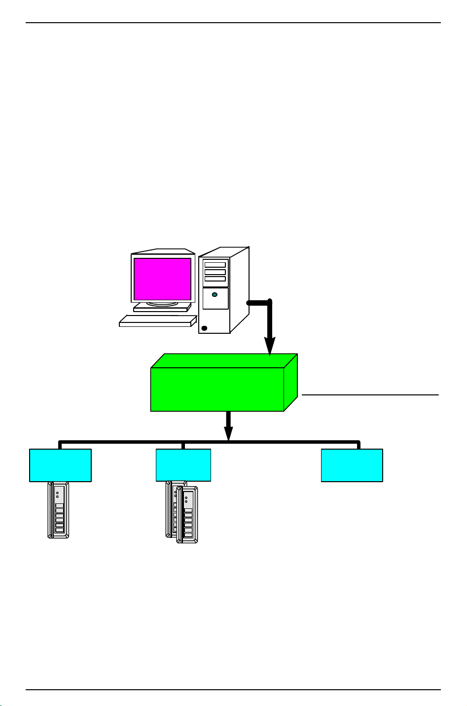
Hardware Installation Guide
Intelligent System
Controller
Downstream Communications
• Two 2-wire ports
• One 4-wire port
16 Downstream
Devices Total
Up to 16 Single
Reader Interface
Modules
(16 Readers)
Up to 16 Dual
Reader Interface
Modules
(32 Readers)
Up to 8 Output Control Modules
or
Alarm Input Control Modules
Single Reader
Interface
Module
Dual Reader
Interface
Module
Input/Output
Control
Module(s)
RS-485
Multi-drop
2 or 4 wire
Access
Control
System
01
23
45
67
89
*
#
01
23
45
67
89
*
#
01
23
45
67
89
*
#
Communications
from Host to Controller
RS-232, RS-485, Ethernet
Dial-up, Fiber, etc...
8 Overview of the LNL-500
This installation guide is intended for use by technicians who will be installing and maintaining the
Intelligent System Controller (LNL-500).
The ISC provides real time processing for the I/O interfaces to which it is connected. It holds the database
for the subsystem configuration and cardholders, the event log buffer in battery-backed memory.
8.1 Interfaces
The ISC interfaces upstream with the Access Control software on a host system and downstream with the
following field hardware components:
Intelligent System Controller Communications Overview
8.2 The Intelligent System Controller Board
The ISC board contains the following components: two (2) unsupervised alarm inputs, one (1) RS-232 or
RS-485 interface, two (2) RS-485 interfaces (which can consist of two 2-wire or one 4-wire interfaces), one
revision 7 — 61
Page 62
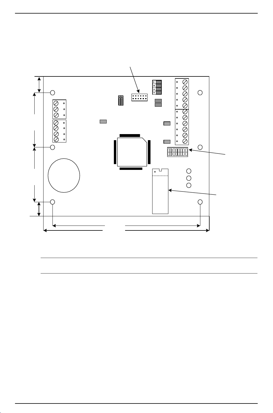
LNL-500 Intelligent System Controller
B
ACDC
AC
GND
GND
GND
IN2
IN1
J4
J7
232
485
2W 4W
TXD
TR1+
RXD
TR1-
RTS
R1+
CTS
R1-
GND
TR2+
TR2-
GND
TR3+
TR3-
GND
J11
J12
S
1
U4
Lithium Ion
3V BR2325
8 7 6 5 4 3 2 1
485 232
J3
J5
J6
J9
A
C
2.00 (50.8)2.00 (50.8)
.50 (12.7)
5.50 (139.7)
6.00 (152.4)
DIP SWITCHES
PROGRAM PROM
J8
J10
J13
.50 (12.7)
FOR ETHERNET APPLICATION:
LANTRONIX COBOX MICRO
RICHCO PLASTICS STANDOFF
(1) power-in input, eight (8) DIP switches, and eleven (11) jumpers. It also contains a set of three (3) status
LEDs and one (1) memory backup (3 volt lithium) battery.
LNL-500 Board
Note: The Cobox connector is only present on LNL-500 boards rev. A, SN 002002 or higher.
62 — revision 7
Page 63
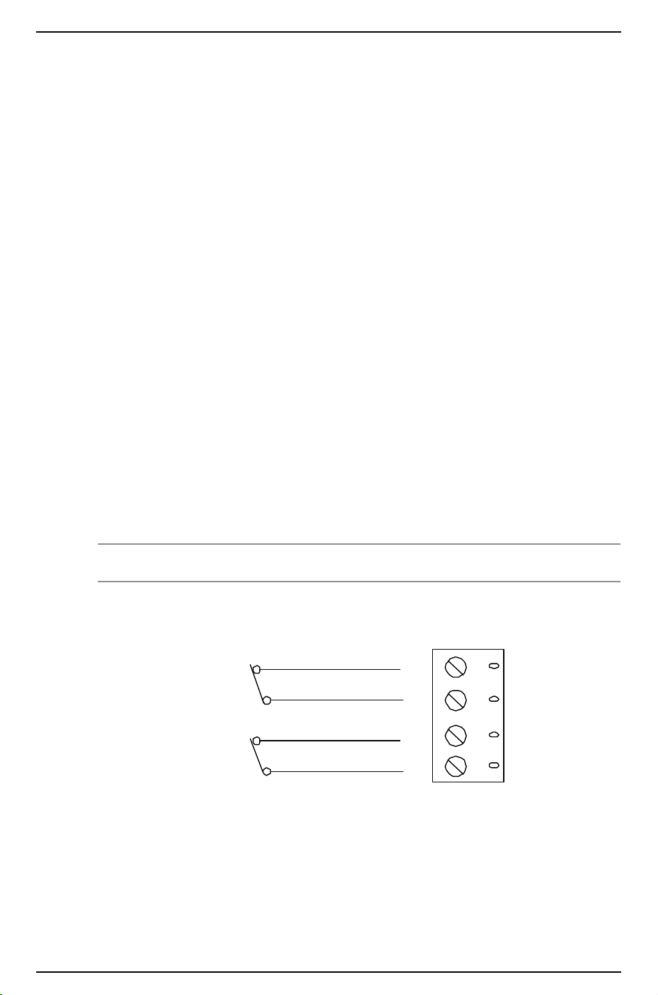
Hardware Installation Guide
GND
IN 2
GND
IN 1
CABINET
TAMPER
POWER
FAULT
9 Installation
To install the ISC, perform the installation procedures described in the following sections, in the order in
which they are presented.
1. Wire the unsupervised alarm inputs for power fault and cabinet tamper monitoring.
2. Wire the upstream host communication.
3. Wire the downstream device communication.
4. Wire the power input.
5. Remove the plastic safety strip from the memory backup battery.
9.1 Wiring
9.1.1 Unsupervised Alarm Inputs: Power Fault and Cabinet Tamper
Monitors
The ISC features two unsupervised alarm inputs that can be used for power fault and cabinet tamper
monitoring. These inputs are connected using the Input 2 (IN2) and Input 1 (IN1) contact terminals on the
ISC board.
Input 2 and Input 1 are both simple N/C (normally closed) contact closure monitors.
Wire the Input 2 and Input 1 contacts using twisted pair cable, 30 ohms maximum. (No EOL resistors are
required.)
Note: If either of these inputs is not used, a shorting wire should be installed.
Unsupervised Alarm Input Wiring
9.1.2 Upstream Host Communication
The ISC uses Port 1 to communicate to the host system. Port 1 can be wired as an RS-232 interface for
direct one-to-one (or modem) communication, or as an RS-485 interface for multi-drop or extended distance
communication.
revision 7 — 63
Page 64

LNL-500 Intelligent System Controller
Direct-connect RS-232 cables should be no longer than 50 feet. Leased lines or fiber optics can also be used.
For RS-485 communication, the following type of RS-485 cable is required: 24 AWG (minimum) twisted
pair (with shields). Either 2-wire or 4-wire RS-485 cable configuration can be used. The RS-485 cable
should be no longer than 4000 feet (1219 m), 120 ohms maximum (Belden 9842 4-wire or 9841 2-wire,
plenum cabling Belden 88102, West Penn, or equivalent.) The drop cables (to readers and other devices)
should be kept as short as possible, no longer than 10 feet.
RS-232 Communications
The RS-232 communications interface is for short distance wiring or point-to-point communications. A
number of products provide RS-232 interfaces such as connections to local printer, modem, PC, etc. This
interface is intended for a short distance communication because its high impedance is more susceptible to
noise. Cable length is generally limited to 50 feet (15.24 m). If required, this distance may be extended to a
few hundred feet by using low capacitance shielded cables. The optimal cable is a Belden 9610 or equivalent
wire.
RS-485 Communications
The (EIA) Electronic Industries Association standard defines RS-485 as an electrical interface for multi-port
communications on a bus transmission line. It allows for high-speed data transfer over extended distance
(4000 feet/1219 m). The RS-485 interface uses a balance of differential transmitter/receiver to reject
common mode noise. For increased reliability over the extended distances end-of-line (EOL) termination is
required.
RS-485 Line Termination
RS-485 (2-wire or 4-wire) must be terminated at both ends of the RS-485 line (bus). Terminating the line
provides a more reliable communication by minimizing the signal reflection and external noise coupling.
Each component provided has an on-board terminator. It is up to the installer to determine which device is at
the End of the communication line. (see diagram below)
Belden (24 gauge wire – (7x32) Stranded Conductors – Polyethylene Insulated)
Belden Wire Specifications
Trade Number
UL NEC Type
CSA
Certification
9841
NEC CM CSA
9842
NEC CM CSA
Number
of Pairs
1 24.0 ohms/M
2 24.0 ohms/M
Nominal
D.C. R.
Conductor
78.7 ohms/
km
78.7 ohms/
km
Shield Nominal
Impedance
(Ohms)
3.35 ohms/M
11.0 ohms/K
2.2 ohms/M
7.2 ohms/K
120 12.8 42
120 12.8 42
Nominal Capacitance
pF/feet pF/meter
64 — revision 7
Page 65
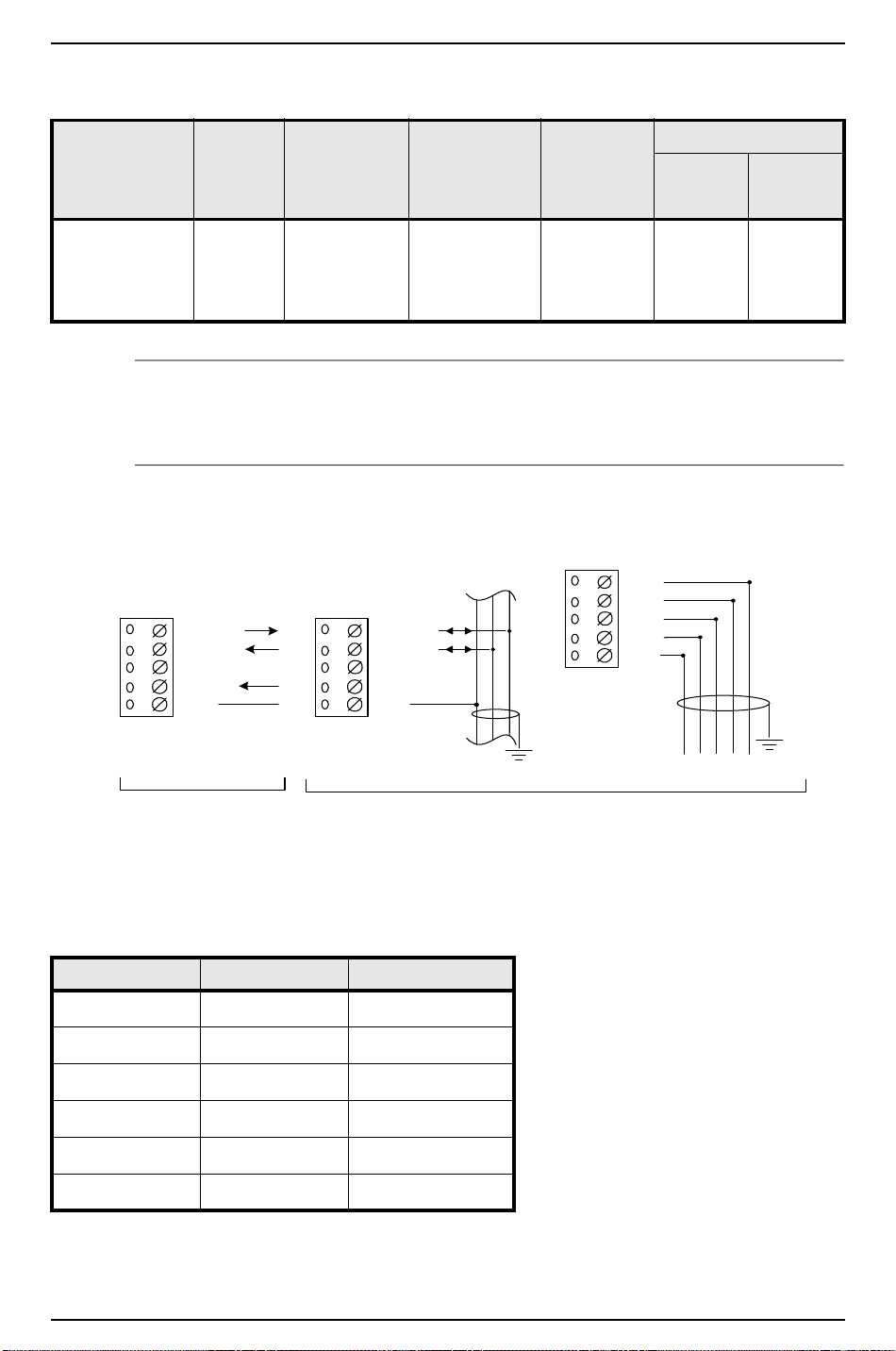
Belden Wire Specifications
PORT 1, CONFIGURED
AS RS-232
Wire wi th 2 4 AWG.
TR1+
TR1-
GND
R1 -
R1 +
4-WIRE
SG T R - TR + R- R+
PORT 1, CONFIGURED AS RS-485
Wire with 24 AWG stranded twisted pair(s) with shield.
TERMINATE RS-485 END OF BUS
TXD/TR1+
RXD/TR1-
GND
CTS/R1 -
RTS/R1 +
TXD/TR1+
RXD/TR1-
GND
CTS/R1 -
RTS/R1 +
2-WIRE
Earth
Ground
Earth
Ground
Hardware Installation Guide
Trade Number
UL NEC Type
CSA
Number
of Pairs
Nominal
D.C. R.
Conductor
Shield Nominal
Impedance
(Ohms)
Nominal Capacitance
pF/feet pF/meter
Certification
88102
NEC CMP CSA
2 24.0 ohms/M
78.7 ohms/
15.5 ohms/M
50.9 ohms/km
100 12.95 42
km
Notes: If RS-485 communication is used, an RS-232 to RS-485 converter is required at the host
workstation.
The 2-wire configuration is recommended over the 4-wire for RS-485.
Upstream Host Communication Wiring (Port 1) for direct connect and Lantronix
Port 1 – wiring configuration. This configuration will work for direct connect (RS-232) and Lantronix
Ethernet network communications. With direct connect and with Lantronix, DIP switch 5 needs to be ON.
ISC 9-pin connector 25 – pin connector
TXD/TR1+ pin 2 pin 3
RXD/TR1- pin 3 pin 2
RTS/R1+ not used not used
CTS/R1- pin 7 pin 4
GND pin 5 pin 7
Jumper together 4, 6 & 8 5,6 & 20
revision 7 — 65
Page 66
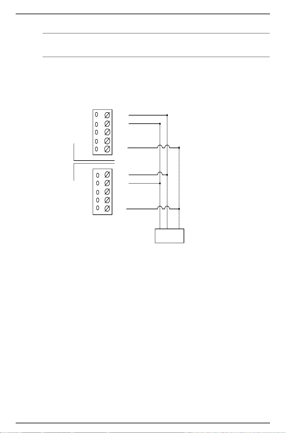
LNL-500 Intelligent System Controller
TR1+
TR1-
GND
R1 -
R1 +
TR1+
TR1-
GND
R1 -
R1 +
ISC Panel 2,
Address 01
ISC Panel 1,
Address 00
2-WIRE MULTIDROP RS- 485 FROM HOST
(Maximum of 8 control panels)
2 3 5
DB9-pi n
Connector
(Jumper Wires
4,6,8 Together)
TO CONTROL ROCKET PORT HO-2062
COMBO BOARD (PORTS 1 AND/OR 2)
Note: To connect the ISC to Rocket Port via 2-wire RS-485, the toggle RTS low checkbox should be
checked in the Rocket Port settings.
2-Wire RS-485 from Host
Wire Configuration – Switch #5 must be off for all panels in this configuration.
9.1.3 Downstream Device Communication
The ISC can be configured to communicate downstream with up to 8 input/output devices, using Port 2 and
Port 3. Each of these ports can be wired only as an RS-485 interface, for multi-drop communication on a
single bus of up to 4000 feet.
For Ports 2-3, the following type of RS-485 cable is required: 24 AWG (minimum) twisted pair (with
shields.) Either 2-wire or 4-wire RS-485 cable configuration can be used. The main run RS-485 cable should
be no longer than 4000 feet (1219 m), 100 ohms maximum (Belden 9842 4-wire or 9841 2-wire, plenum
cabling Belden 88102, West Penn, or equivalent). The drop cables (to readers and other devices) should be
kept as short as possible, no longer than 10 feet.
Each RS-485 line should contain only 2 terminators, one at each end.
66 — revision 7
Page 67
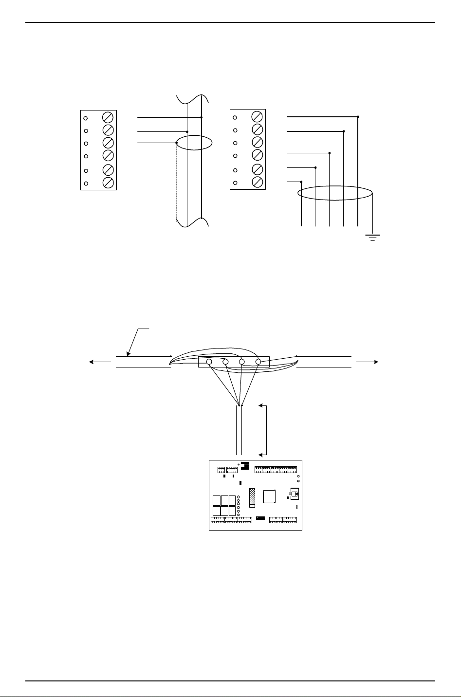
Downstream Device Communication Wiring (Ports 2-3)
TR2 +
TR2 -
GND
TR3 +
TR3 -
GND
2-WIRE
TR2 +
TR2 -
GND
TR3 +
TR3 -
GND
GND TR- TR+ R- R+
Downstream Device
4-WIRE
GND T- T+
Ports 2 - 3
RS-485
Earth
Ground
KEEP DOWN LEAD SHORT
(10 FEET MAX.)
TO NE XT UNIT
OR TERMINATOR
TO PREVIOUS UNIT
OR TERMINATOR
RS-485 CABLE, 100 Ohm IMPEDANCE
BELDEN 9842 OR EQUIVALENT
Reader Interfac e Module
Hardware Installation Guide
RS-485 Communication Wiring
To configure all four downstream ISC ports as 2-wire RS-485, follow the 2-wire diagram and repeat on each
set of three terminators, TRX+, TRX-, GND.
revision 7 — 67
Page 68

LNL-500 Intelligent System Controller
ACDC
AC
GND
ACDC
AC
GND
12 V
12 VAC
12 V
+
–
12 VDC
... OR ...
To configure as two 4-wire RS-485 ports, follow the 4-wire diagram:
Port 2/3: (Transmit)
TR2+, TR2-
(Receive)
TR3+, TR3-
GRD
Notes: The ISC can be located anywhere along the RS-485 line.
Install an RS-485 terminator for each end-of-line device.
9.1.4 Power
The ISC accepts either a 12 VDC or 12 VAC ± 15% power source for its power input. The power source
should be located as close to the ISC as possible.
Wire the power input with 18 AWG (minimum) twisted pair cable.
For AC power sources, the following lines are required: AC Line (L), AC Neutral (N). These lines must not
be interchanged. A 400 mA RMS current is required for AC power supplies.
For DC power sources, isolated and non-switching, regulated DC power is required. A 250 mA current is
required for DC power supplies.
Note: If using a 12 VDC power source, be sure to observe polarity.
Power Source Wiring
9.1.5 Other
Remove the factory-installed plastic safety strip from the memory backup battery. This plastic strip prevents
the battery from being effectively seated. The battery will not function properly until the plastic strip is
removed. When the battery is enabled, all volatile RAM is protected.
Note: You must first remove the plastic strip to enable the battery.
68 — revision 7
Page 69
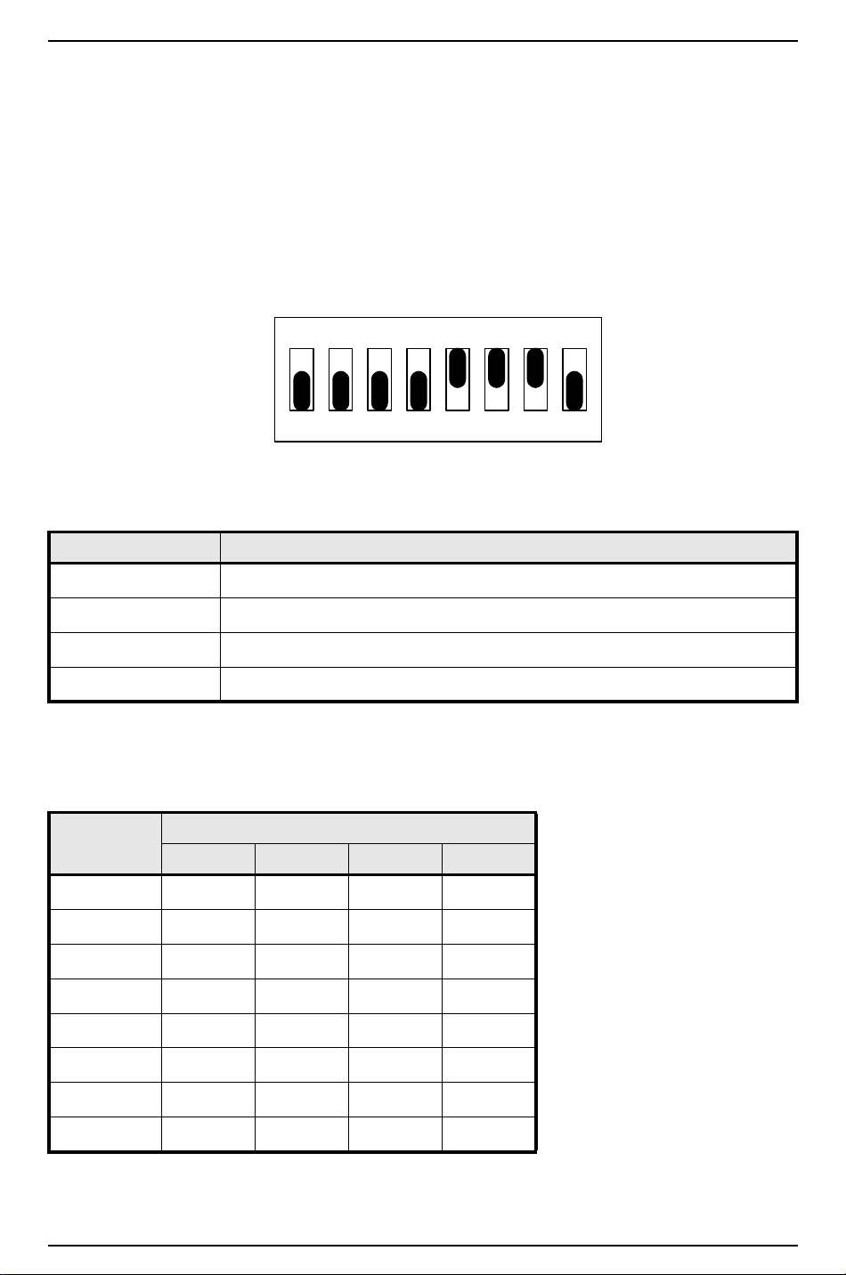
Hardware Installation Guide
ON ON ON
12345678
10 Configuration
The ISC board contains 8 DIP switches and 12 jumpers that must be configured appropriately for your
system.
10.1 Setting DIP Switches
DIP Switches (illustrated: default address of 0, CTS enabled, baud rate = 38400)
The following chart describes the use of each DIP switch.
DIP SWITCH(ES) USED TO CONFIGURE:
1, 2, 3, 4 Processor address (0 – 7)
5 Communication handshake status (“CTS enabled” or “none”)
6, 7 Communication baud rate (38400, 19200, 9600 bps)
8 Communication password status (“required”, “not required”)
10.1.1 Processor Address
To configure the processor address, set DIP switches 1, 2, 3, and 4 according to the following table.
Address DIP SWITCH
1: 2: 3: 4:
0 (default) off off off off
1 ON off off off
2 off ON off off
3ONONoff off
4 off off ON off
5ON off ON off
6off ON ON off
7ONONONoff
revision 7 — 69
Page 70
LNL-500 Intelligent System Controller
10.1.2 Communication Handshake Status
To configure the communication handshake status, set DIP switch 5 according to the following table. Leave
this feature set to ON for Lantronix, dial-up, and RS-232, and OFF for RS-485 communication.
HANDSHAKE
STATUS
Transmit enabled by CTS
(default)
None off
DIP SWITCH
5:
ON
10.1.3 Communication Baud Rate
To configure the communication baud rate, set DIP switches 6 and 7 according to the following table. This
feature controls the baud rate for upstream communication.
BAUD RATE DIP SWITCH
6: 7:
38400 bps (default) ON ON
19200 bps off ON
9600 bps ON off
(not used) off off
10.1.4 Communication Password Status
DIP switch 8 controls the utilization of encryption.
The ISC supports encryption with use of AES firmware. The controller must have a 256 KB chip. If you
wish to use this feature and have a controller with a 128 KB chip, it must be upgraded.
PASSWORD STATUS DIP SWITCH 8:
Encryption is optional off
Encryption is required ON
Turn DIP switch 8 ON to enhance security. When a host system attempts to communicate with an
encryption-enabled controller, a proper master key is required.
Note: The controller only reads DIP switch settings when it is powered up. If DIP switch settings are
changed, the controller must go through a power cycle before the changes are seen.
70 — revision 7
Page 71
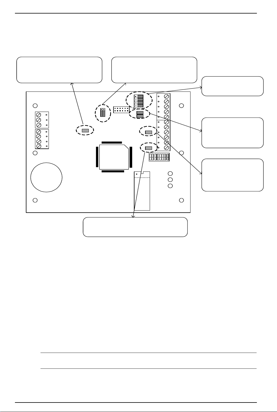
Hardware Installation Guide
[J13]
OFF: Port 1, Ethernet (Cobox-micro)
ON: Port 1, serial (RS-232/RS-485)
B
ACDC
AC
GND
GND
GND
IN2
IN1
J4
J7
232 485
2W 4W
TXD
TR1+
RXD
TR1-
RTS
R1+
CTS
R1-
GND
TR2+
TR2-
GND
TR3+
TR3-
GND
J11
J12
S
1
U4
Lithi um Ion
3V B R2325
8 7 6 5 4 3 2 1
485 232
J3
J5
J6
J9
A
C
J8
J10
J13
[J12]
OFF: Port 3 RS-485 EOL termination is not on
ON: Port 3 RS-485 EOL terminat ion is on
[J4]
Control for Port 1, RS-232 or RS-485
[J7]
Control f or Port 1, 2-wire or 4-wire
[J11]
OFF: Port 2 RS-485 EOL
termination is not on
ON: Port 2 RS-485 EOL
termination is on
[J8, J10]
OFF: Port 1 RS-485 EOL
termination is not on
ON: Port 1 RS-485 EOL
termination is on
[J3, J5, J6, J9]
Control for Port 1, RS-232
or RS-485
10.2 Installing Jumpers
The following diagram describes the use of each jumper on the ISC board. The jumper is indicated by
brackets [ ]. The default shipping position is shown below.
10.2.1 RS-485 Cable Termination from Host to ISC
The device used to convert RS-232 communication to RS-485 determines the termination necessary for this
segment of the RS-485 communication bus. These communications devices, pre-bias the RS-485 signal,
which marks the state of the signal being sent and allows the line to flow for reliable communications. This
is true for most devices that are used for Host to ISC communications, but any device that has been approved
by Lenel will indicate how termination should be configured for proper operation in its documentation.
10.2.2 RS-485 Cable Termination from ISC to Downstream Modules
Termination of this section of the RS-485 bus always remains the same. Each end of the RS-485 bus must be
terminated using the on-board jumpers provided with each piece of hardware. Please refer to the termination
drawings for each component being installed in this hardware manual.
Note: This applies to Ports 2 and 3.
revision 7 — 71
Page 72

LNL-500 Intelligent System Controller
A
B
C
11 Maintenance
Refer to
firmware.
Firmware Updates in the Hardware Installation Guidelines section for instructions for downloading
11.1 Verification
The ISC board contains three Status LEDs (LED A, LED B, LED C) that can be used to verify correct
installation after power up.
The following chart describes the purpose of each LED on the ISC board.
LED Purpose
A This LED blinks rapidly whenever the ISC is powered up and is operating normally.
B This LED is on when upstream communication to host computer is in process.
C This LED is on when downstream communication to reader interfaces or input/
output modules is in process.
11.2 Replace Memory Backup Battery
The ISC contains a Memory Backup battery that is used to backup configuration data and event buffer data
in the event of a power failure.
A 3 V lithium ion battery (Rayovac BR2325 or Wuhan Lixing CR2330) is used for the Memory Backup.
This battery should be replaced annually.
Caution: There is a danger of explosion if the battery is incorrectly replaced. Replace only
with the same or equivalent type recommended by the manufacturer. Dispose of
used batteries in accordance with the manufacturer's instructions.
72 — revision 7
Page 73

Hardware Installation Guide
12 Specifications
The LNL-500 is for use in low voltage, class 2 circuits only.
• Primary Power: (DC or AC)
- DC input: 12 VDC ± 10%. 250 mA
- AC input: 12 VAC ± 15%. 400 mA RMS
• Memory and Clock Backup: 3 V lithium, type BR2325
• Communication Ports:
- Port 1: RS-232 or RS-485, 9600 to 38400 bps async
- Ports 2-3: RS-485 (2-wire), 9600 to 38400 bps async
• Inputs:
- Cabinet Tamper Monitor: unsupervised, dedicated
- Power Fault Monitor: unsupervised, dedicated
• Wire Requirements:
- Power: 1 stranded twisted pair, 18 AWG
- RS-485: 24 AWG stranded twisted pair(s) with shield, 4000 feet (1219 m) maximum
- RS-232: 24 AWG stranded, 50 feet (15.24 m) maximum
- Alarm Input: stranded twisted pair, 30 ohms maximum
• Environmental:
- Temperature: Operating: 0° to +70° C (32° to 158° F)
- Humidity: 0 to 95% RHNC
• Mechanical:
- Dimension: 6 x 5 x 1 in. (152 x 127 x 25 mm)
- Weight: 8 oz. (227 g) nominal
• Data Memory: 512 KB
• Certifications:
- UL294 & UL1076 Listed
-ULC Listed
-FCC Part 15
-C-Tick
- FIPS 197 Certificate #305
-CE marking
- RoHS compliant
- WEEE
Note: These specifications are subject to change without notice.
revision 7 — 73
Page 74

LNL-500 Intelligent System Controller
74 — revision 7
Page 75

LNL-1000
INTELLIGENT
SYSTEM
CONTROLLER
Page 76

Page 77
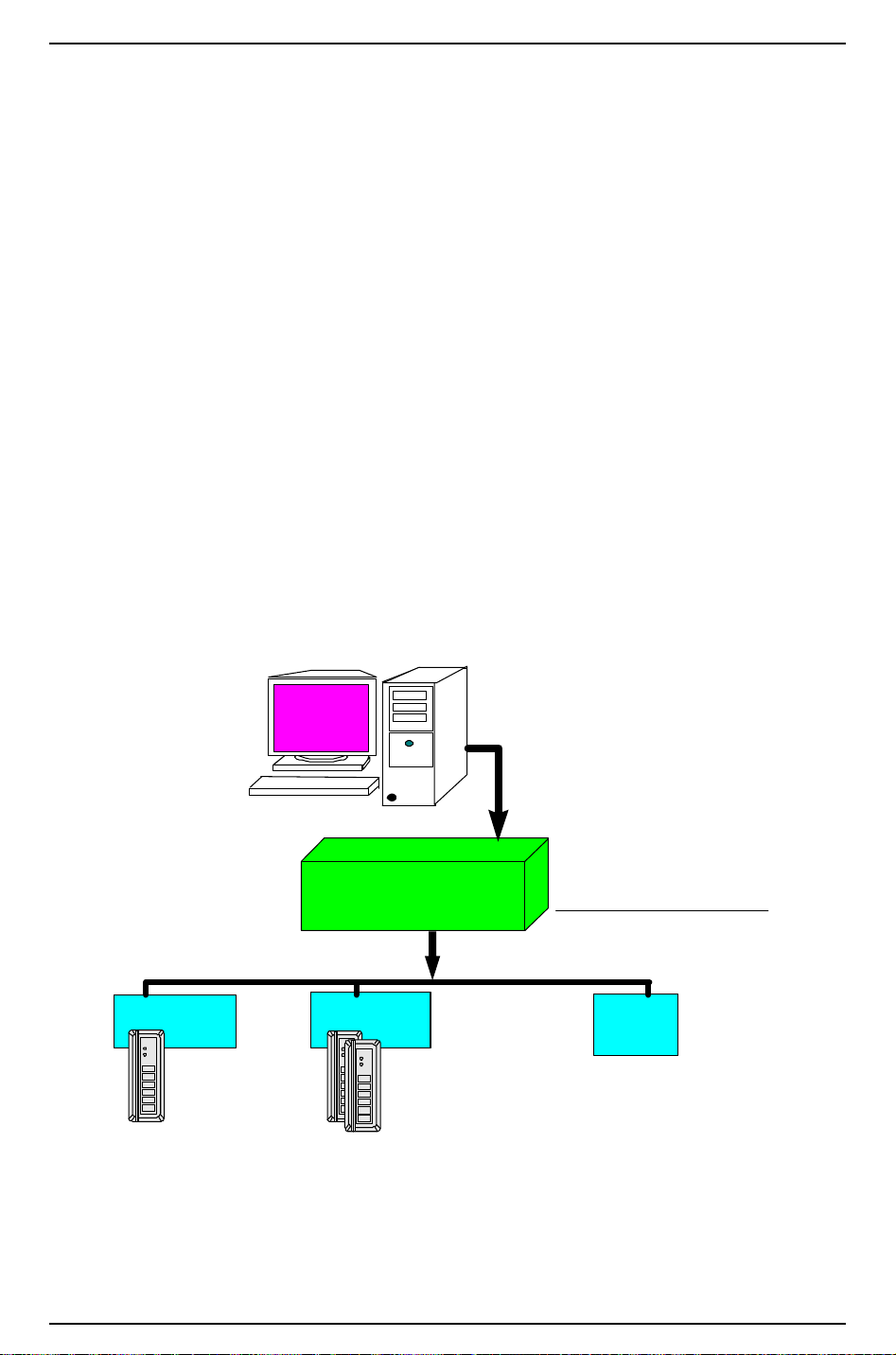
Hardware Installation Guide
Intelligent System
Controller
Downstream Communications
• Four 2-wire ports
• Two 4-wire ports
• Combination 2 and 4 wire ports
32 Downstream
Devices Total
Up to 32 Single
Reader Interface
Modules
(32 readers)
Up to 32 Dual
Reader Interface
Modules
(64 readers)
Up to 16 Output Control Modules
Up to 16 Alarm Input Control Modules
Single Reader
Interface Module
Dual Reader
Interface Module
Input/Output
Control
Module(s)
RS- 485
Multi-drop
2 or 4 wire
Access
Control
System
01
23
45
67
89
*
#
01
23
45
67
89
*
#
01
23
45
67
89
*
#
Communications
from Host to Controller
RS-232, RS-485, Ethernet
Dial-up, Fiber, etc...
13 Overview of the LNL-1000
This installation guide is intended for use by technicians who will be installing and maintaining the
Intelligent System Controller.
The Intelligent System Controller (ISC) serves as the predominant access control engine. The ISC provides
power, performance, and flexibility for the most demanding applications. Multiple combinations of Alarm
Input Control Modules, Output Control Modules, and card reader interface modules can be configured.
The ISC can communicate upstream at 38.4 Kbps via RS-232, RS-485 multi-dropped configurations,
modem dial-up communications, Ethernet TCP/IP networks, or Token Ring networks. The standard ISC can
store 5,000 cardholders and 100,000 events, with expansion capabilities for up to 250,000 cardholders and 1
million events. The ISC has four downstream 2-wire RS-485 channels or two 4-wire RS-485 channels. In
either configuration you may connect up to 64 readers or 32 devices on a single Intelligent System
Controller. Each SRI, DRI, ICM and OCM takes up one device address.
13.1 Interfaces
The ISC interfaces upstream with the Access Control software on a host system, and downstream with the
following field hardware components:
Intelligent System Controller Communications Overview
revision 7 — 77
Page 78
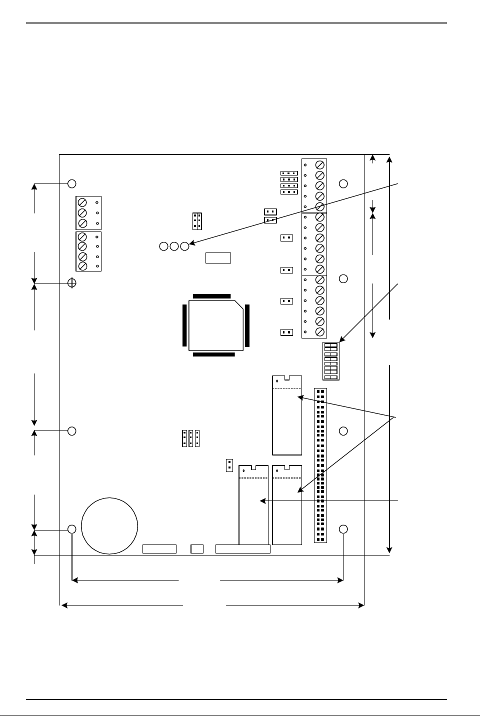
LNL-1000 Intelligent System Controller
ACDC
AC
GND
GND
GND
IN2
IN1
A B C
J9
J14
232
485
2W 4W
J1
TXD
TR1+
RXD
TR1-
RTS
R1+
CTS
R1-
GND
TR2+
TR2-
GND
TR3+
TR3-
GND
TR4+
TR4-
GND
TR5+
TR5-
GND
J10
J11
J12
J13
J8
J7
J15
J16
J17
J18
1 2 3 4 5 6 7 8
J5
S1
U15
U16
U17
J6
2 MEG
SNRE VPN
J3J2J4
5.50 (139.7)
6.00 (152.4)
8.00 (203.2)
0.50 (12.7) 2.00 (50.8) 3.00 (76.2) 2.00 (50.8)
RS-485 PORTS RS-232/RS-485 PORT
STATUS LED ' s
DIP SWITCHES
MEMORY PROMS
PROG RAM PROM
LITHIUM
ION 3V
BR2325
13.2 The ISC Board
The ISC board contains the following components: two (2) unsupervised alarm inputs, one (1) RS-232 or
RS-485 interface, four (4) RS-485 interfaces (which can consist of four 2-wire, two 4-wire, or one 4-wire
and two 2-wire interfaces), one (1) power-in input, eight (8) DIP switches, and sixteen (16) jumpers. It also
contains a set of three (3) status LEDs and one (1) memory backup (3 volt lithium) battery.
The ISC Board
78 — revision 7
Page 79
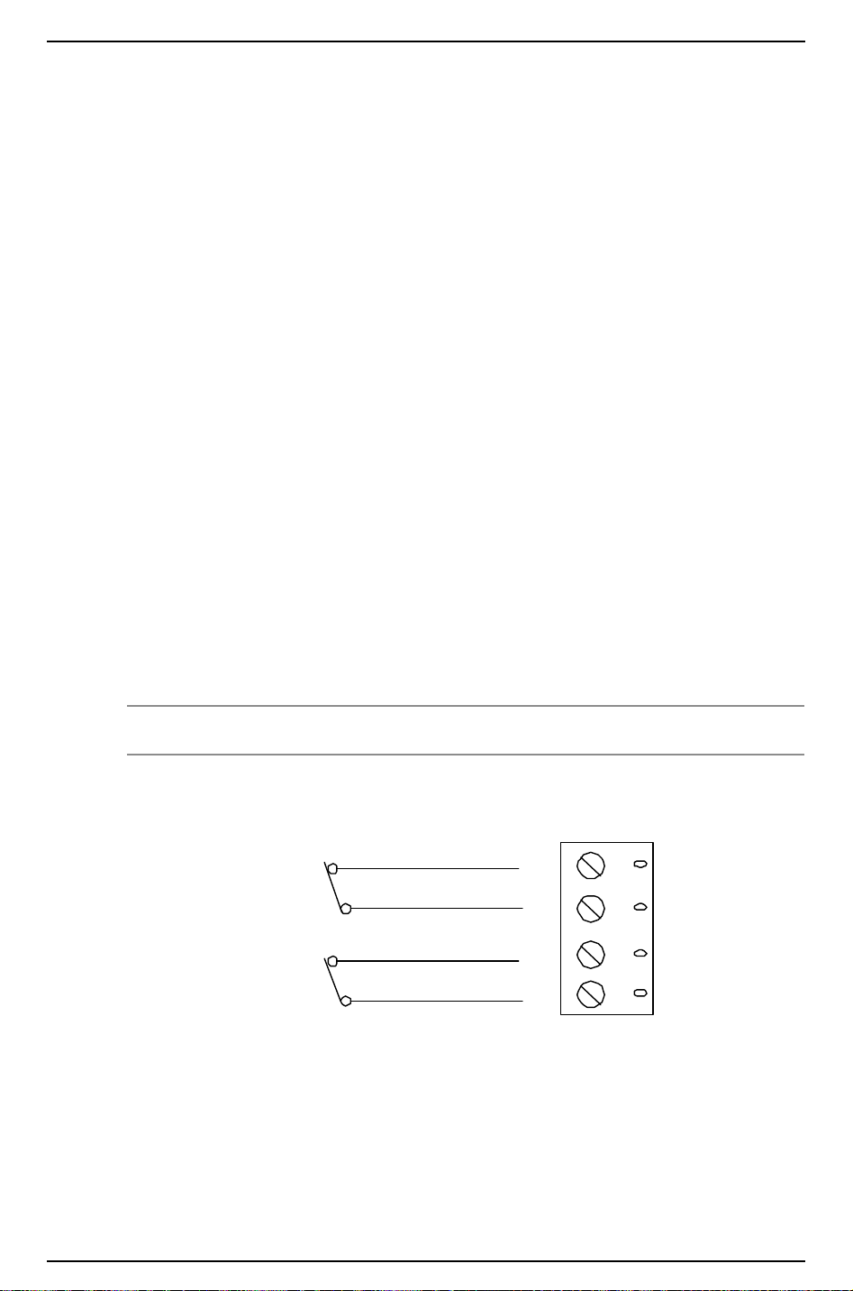
Hardware Installation Guide
GND
IN 2
GND
IN 1
CABINET
TAMPER
POWER
FAULT
14 Installation
To install the ISC, perform the installation procedures described in the following sections, in the order in
which they are presented.
1. Wire the unsupervised alarm inputs for power fault and cabinet tamper monitoring.
2. Wire the upstream host communication.
3. Wire the downstream device communication.
4. Wire the power input.
5. Remove the plastic safety strip from the memory backup battery.
14.1 Wiring
14.1.1 Unsupervised Alarm Inputs: Power Fault and Cabinet Tamper
Monitors
The ISC features two unsupervised alarm inputs that can be used for power fault and cabinet tamper
monitoring. These inputs are connected using the Input 2 (IN2) and Input 1 (IN1) contact terminals on the
ISC board.
Input 2 and Input 1 are both simple N/C (normally closed) contact closure monitors.
Wire the Input 2 and Input 1 contacts using twisted pair cable, 30 ohms maximum. (No EOL resistors are
required.)
Note: If either of these inputs is not used, a shorting wire should be installed.
Unsupervised Alarm Input Wiring.
14.1.2 Upstream Host Communication
The ISC uses Port 1 to communicate to the host system. Port 1 can be wired as an RS-232 interface for direct
one-to-one (or modem) communication, or as an RS-485 interface for multi-drop or extended distance
communication.
revision 7 — 79
Page 80

LNL-1000 Intelligent System Controller
Direct-connect RS-232 cables should be no longer than 50 feet. Leased lines or fiber optics can also be used.
For RS-485 communication, the following type of RS-485 cable is required: 24 AWG (minimum) twisted
pair (with shields.) Either 2-wire or 4-wire RS-485 cable configuration can be used. The RS-485 cable
should be no longer than 4000 feet (1219 m), 100 ohms maximum (Belden 9842 4-wire or 9841 2-wire,
plenum cabling Belden 88102, West Penn, or equivalent.) The drop cables (to readers and other devices)
should be kept as short as possible, no longer than 10 feet.
RS-232 Communications
The RS-232 communications interface is for short distance wiring or point to point communications. A
number of products provide RS-232 interfaces such as connections to local printer, modem, PC, etc. This
interface is intended for a short distance communication because its high impedance is more susceptible to
noise. Cable length is generally limited to 50 feet (15.24 m). If required, this distance may be extended to a
few hundred feet by using low capacitance shielded cables. The optimal cable is a (Belden 9610) or
equivalent wire.
RS-485 Communications
The (EIA) Electronic Industries Association standard defines RS-485 as an electrical interface for multiport
communications on a bus transmission line. It allows for high-speed data transfer over extended distance
(4000 feet, 1219 m). The RS-485 interface uses a balance of differential transmitter/receiver to reject
common mode noise. For increased reliability over the extended distances End-of-line (EOL) termination is
required.
RS-485 Line Termination
RS-485 (2-wire or 4-wire) must be terminated at both ends of the RS-485 line (bus). Terminating the line
provides a more reliable communication by minimizing the signal reflection and external noise coupling.
Each has an on-board terminator. It is up to the installer to determine which device is at the End of the
communication line (see diagram).
Belden (24 gauge wire – (7x32) Stranded Conductors – Polyethylene Insulated)
Belden Wire Specifications
Trade Number
UL NEC Type
CSA
Certification
9841
NEC CM CSA
9842
NEC CM CSA
Numbe
r of
Pairs
1 24.0 ohms/M
2 24.0 ohms/M
Nominal
D.C. R.
Conductor
78.7 ohms/
km
78.7 ohms/
km
Shield Nominal
Impedance
(Ohms)
3.35 ohms/M
11.0 ohms/K
2.2 ohms/M
7.2 ohms/K
120 12.8 42
120 12.8 42
Nominal
Capacitance
pF/feet pF/
meter
80 — revision 7
Page 81
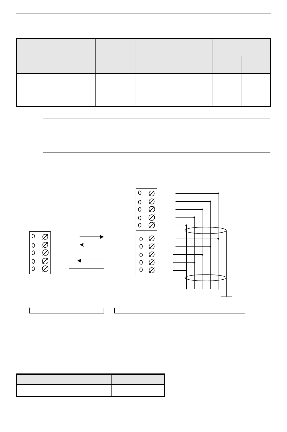
Belden Wire Specifications
TXD/TR1+
RXD/TR1-
GND
CTS/R1 -
RTS/R1 +
PORT 1,
CONFIGURED as RS-232
Wire with 24 AWG stranded
TR1+
TR1-
GND
R1 -
R1 +
4-WIRE
GND TR- TR+ R- R+
PORT 1,
CONFIGURED AS RS-485
Wire with 24 AWG stranded twisted pair with shield
TR1+
TR1-
GND
R1 -
R1 +
ISC Port 1,
Address 00
(J7, J8 off)
ISC Port 1,
Address 01
(J7, J8 on)
TERMINATE RS-485 END OF BUS
Earth
Ground
Hardware Installation Guide
Trade Number
UL NEC Type
CSA
Certification
88102
NEC CMP CSA
Numbe
r of
Pairs
Nominal
D.C. R.
Conductor
2 24.0 ohms/M
78.7 ohms/
Shield Nominal
Impedance
(Ohms)
15.5 ohms/M
100 12.95 42
50.9 ohms/km
Nominal
Capacitance
pF/feet pF/
meter
km
Notes: If RS-485 communication is used, an RS-232 to RS-485 converter is required at the host
workstation.
The 2-wire configuration is recommended over the 4-wire for RS-485.
Upstream Host Communication Wiring (Port 1)
Port 1 – wiring configuration. This configuration will work for Direct connect (RS-232) and Lantronix
Ethernet network communications. With direct connect and with Lantronix, DIP switch 5 needs to be ON.
ISC 9-pin connector 25 – pin connector
TXD/TR1+ pin 2 pin 3
revision 7 — 81
Page 82
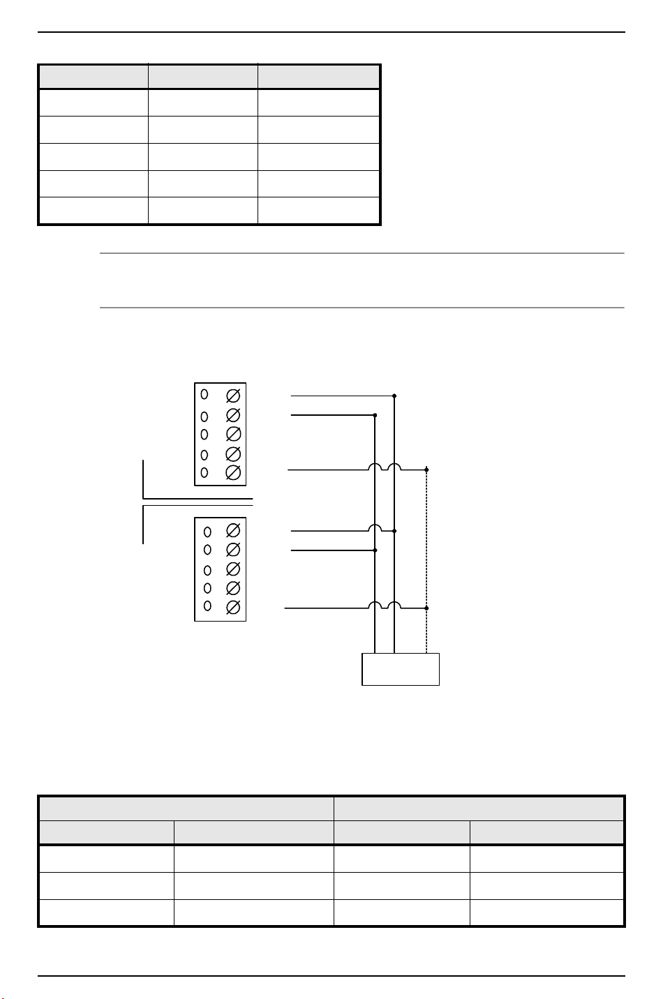
LNL-1000 Intelligent System Controller
TR1+
TR1-
GND
R1 -
R1 +
TR1+
TR1-
GND
R1 -
R1 +
ISC Panel 2,
Address 01
ISC Panel 1,
Address 00
2-WIRE MULTIDROP RS-485 FROM HOST
(Maximum of 8 control panels)
2 3 5
DB9-pin
Connector
(Jumper Wires
4,6,8 Together)
TO CONTROL ROCKET PORT HO-2062
COMBO BOARD (PORTS 1 AND/OR 2)
ISC 9-pin connector 25 – pin connector
RXD/TR1- pin 3 pin 2
RTS/R1+ not used not used
CTS/R1- pin 7 pin 4
GND pin 5 pin 7
Jumper together 4, 6 & 8 5,6 & 20
Note: To connect the ISC to Rocket Port via 2-wire RS-485, the toggle RTS low checkbox should be
checked in the Rocket Port settings.
Wire Configuration – Switch #5 must be off for all panels in this configuration.
Panel 1 Panel 2
Jumper Setting Jumper Setting
J7, J8 Off J7, J8 On
J9, J10, J11, J12, J13 RS-485 J9, J10, J11, J12, J13 RS-485
J14 2-wire J14 2-wire
82 — revision 7
Page 83
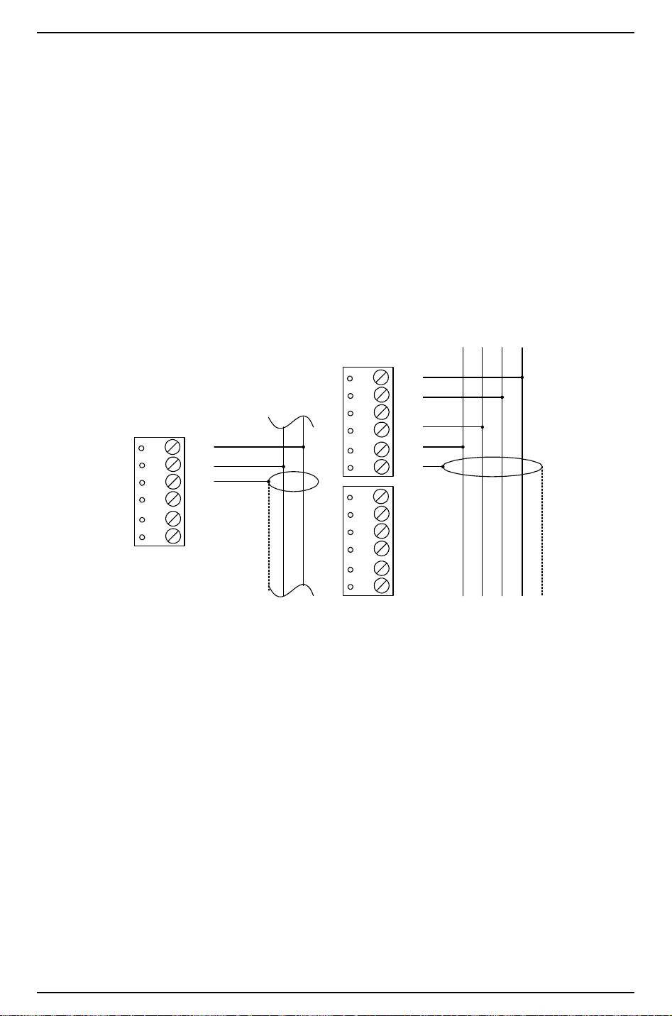
Hardware Installation Guide
TR2 +
TR2 -
GND
TR3 +
TR3 -
GND
2-WIRE
TR2 +
TR2 -
GND
TR3 +
TR3 -
GND
GND
GND
TR4 +
TR4 -
TR5 +
TR5 -
TR- TR+ R- R+ SG
Downstream Dev ice
4-WIRE
Ports 2 - 5
RS-485
GND T- T+
14.1.3 Downstream Device Communication
The ISC can be configured to communicate downstream with up to 16 input/output devices, using Port 2,
Port 3, Port 4, and Port 5. Each of these ports can be wired only as an RS-485 interface, for multi-drop
communication on a single bus of up to 4000 feet.
For Ports 2-5, the following type of RS-485 cable is required: 24 AWG (minimum) twisted pair (with
shields.) Either 2-wire or 4-wire RS-485 cable configuration can be used. The main run RS-485 cable should
be no longer than 4000 feet (1219 m), 100 ohms maximum (Belden 9842 4-wire or 9841 2-wire, plenum
cabling Belden 88102 or equivalent). The drop cables (to readers and other devices) should be kept as short
as possible, no longer than 10 feet.
Each RS-485 line should contain only 2 terminators, one at each end.
Downstream Device Communication Wiring (Ports 2-5)
revision 7 — 83
Page 84
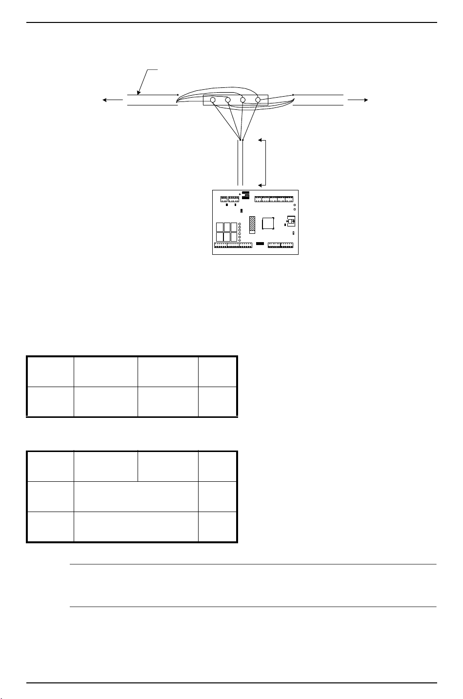
LNL-1000 Intelligent System Controller
KEEP DOWN LEAD SHORT
(10 FEET MAX.)
TO NE XT UNIT
OR TERMINATOR
TO PREVIOUS UNIT
OR TERMINATOR
RS-48 5 CABL E, 10 0 Ohm IMPEDANCE
BELDEN 9842 OR EQUIVALENT
Reader Interface Module
RS-485 Communication Wiring
To configure all four downstream ISC ports as 2-wire RS-485, follow the 2-wire diagram and repeat on each
set of three terminators, TRX+, TRX-, GND.
To configure as two 4-wire RS-485 ports, follow the 4-wire diagram:
Port 2/3: (Transmit)
TR2+, TR2-
Port 4/5: (Transmit)
TR4+, TR4-
(Receive)
TR3+, TR3-
(Receive)
TR5+, TR5-
GRD
GRD
or combine 2-wire and 4-wire RS-485:
Port 2/3:
4-wire
Port 4:
2-wire
Port 5:
(Transmit)
TR2+, TR2-
TR4+, TR4- GRD
(Receive)
TR3+, TR3-
GRD
TR5+, TR5- GRD
2-wire
Notes: The ISC can be located anywhere along the RS-485 line.
Install an RS-485 terminator for each end-of-line device.
84 — revision 7
Page 85

Hardware Installation Guide
ACDC
AC
GND
ACDC
AC
GND
12 V
12 VAC
12 V
+
–
12 VDC
... OR ...
14.1.4 Power
The ISC accepts either a 12 VDC or 12 VAC ± 15% power source for its power input. The power source
should be located as close to the ISC as possible.
Wire the power input with 18 AWG (minimum) twisted pair cable.
For AC power sources, the following lines are required: AC Line (L), AC Neutral (N). These lines must not
be interchanged. A 600mA RMS current is required for AC power supplies.
For DC power sources, isolated and non-switching, regulated DC power is required. A 350mA current is
required for DC power supplies.
Note: If using a 12 VDC power source, be sure to observe polarity.
Power Source Wiring
14.1.5 Other
Remove the factory-installed plastic safety strip from the Memory Backup battery. This plastic strip prevents
the battery from being effectively seated. The battery will not function properly until the plastic strip is
removed. When the battery is enabled, all volatile RAM is protected.
Note: You must first remove the plastic strip to enable the battery.
revision 7 — 85
Page 86
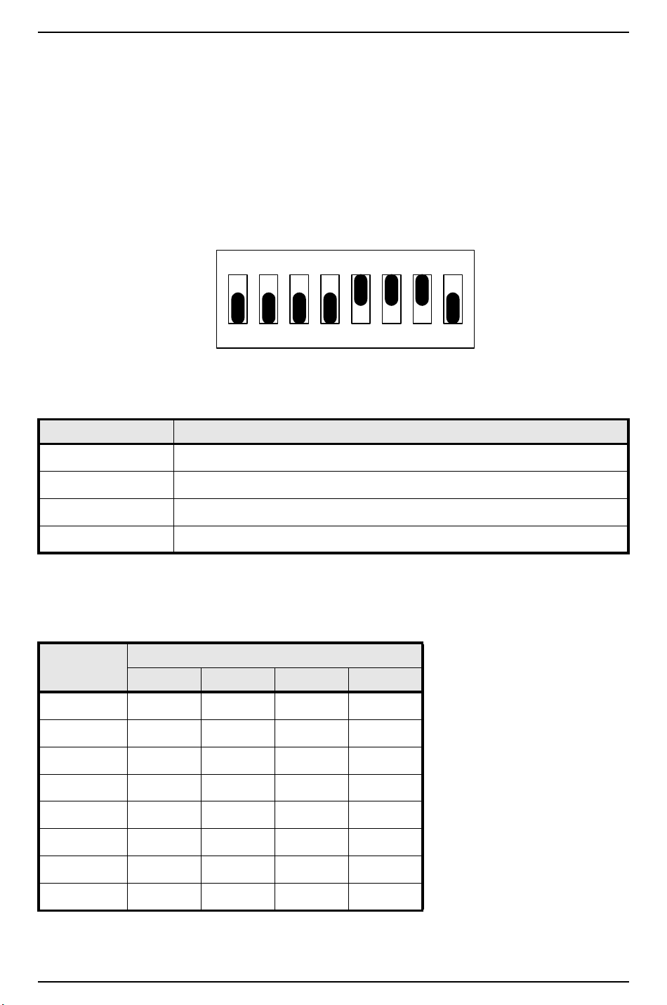
LNL-1000 Intelligent System Controller
ON ON ON
12345678
15 Configuration
The ISC board contains 8 DIP switches and 16 jumpers that must be configured appropriately for your
system.
15.1 Setting DIP Switches
DIP Switches (illustrated: default address of 0, CTS enabled, baud rate = 38400)
The following chart describes the use of each DIP switch.
DIP SWITCH(ES) USED TO CONFIGURE:
1, 2, 3, 4 Processor address (0 – 7)
5 Communication handshake status (“CTS enabled” or “none”)
6, 7 Communication baud rate (38400, 19200, 9600 bps)
8 Communication password status (“required”, “not required”)
15.1.1 Processor Address
To configure the processor address, set DIP switches 1, 2, 3, and 4 according to the following table.
Address DIP SWITCH
1: 2: 3: 4:
0 (default) off off off off
1 ON off off off
2 off ON off off
3ONONoff off
4 off off ON off
5ON off ON off
6off ON ON off
7ONONONoff
86 — revision 7
Page 87
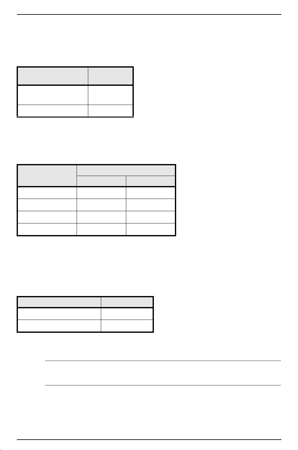
Hardware Installation Guide
15.1.2 Communication Handshake Status
To configure the communication handshake status, set DIP switch 5 according to the following table. Leave
this feature set to ON for Lantronix, dial-up, and RS-232, and OFF for RS-485 communication.
HANDSHAKE
STATUS
Transmit enabled by CTS
(default)
None off
DIP SWITCH
5:
ON
15.1.3 Communication Baud Rate
To configure the communication baud rate, set DIP switches 6 and 7 according to the following table. This
feature controls the baud rate for upstream communication.
BAUD RATE DIP SWITCH
6: 7:
38400 bps (default) ON ON
19200 bps off ON
9600 bps ON off
(not used) off off
15.1.4 Communication Password Status
DIP switch 8 controls the utilization of encryption.
The ISC supports encryption with use of AES firmware. The controller must have a 256 KB chip. If you
wish to use this feature and have a controller with a 128 KB chip, it must be upgraded.
PASSWORD STATUS DIP SWITCH 8:
Encryption is optional off
Encryption is required ON
Turn DIP switch 8 ON to enhance security. When a host system attempts to communicate with an
encryption-enabled controller, a proper master key is required.
Note: The controller only reads DIP switch settings when it is powered up. If DIP switch settings are
changed, the controller must go through a power cycle before the changes are seen.
revision 7 — 87
Page 88
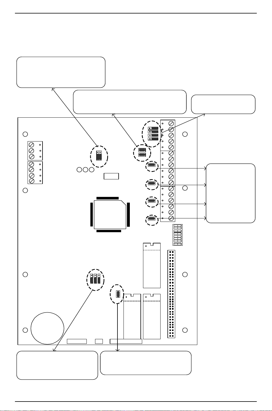
LNL-1000 Intelligent System Controller
[J9]
Control for Port 1, RS-232 or RS-485
[J14]
Control for Port 1, 2-wire or 4-wire
ACDC
AC
GND
GND
GND
IN2
IN1
A B C
J9
J14
232 485
2W 4W
J1
TXD
TR1+
RXD
TR1-
RTS
R1+
CTS
R1-
GND
TR2+
TR2-
GND
TR3+
TR3-
GND
TR4+
TR4-
GND
TR5+
TR5-
GND
J10
J11
J12
J13
J8
J7
J15
J16
J17
J18
1 2 3 4 5 6 7 8
J5
S1
U15
U16
U17
J6
2 MEG
SNREVPN
J3J2J4
LITHIUM
ION 3V
BR2325
[J2, J3, J4]
By default, these jumpers are set
to 512K and should not be
changed.
[J6]
PROM: By default, t his is preconfigured and should not be changed.
[J10, J11, J12, J13]
Control for Port 1, RS-232
or RS-485
[J7, J8]
OFF: Port 1 RS-485 EOL termininat ion is not on
ON: Port 1 RS-485 EOL termination is on
[J15, J16, J17, J18]
for Ports 2, 3, 4, 5,
respectively
OFF: RS-485 EOL
termination is not on
ON: RS-485 EOL
termination is on
15.2 Installing Jumpers
The following diagram describes the use of each jumper on the ISC board. The jumper is indicated by
brackets [ ]. The default shipping position is shown below.
88 — revision 7
Page 89
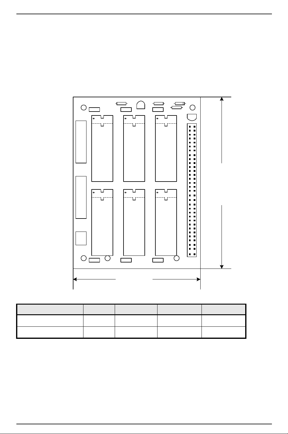
Hardware Installation Guide
3.00 (76.20)
4.00 (101.60)
U1 U3 U5
U2 U4 U6
SN PN REV
MEMORY
C6 C5 C4
R3
R2
C3
C2 C1
C8
C7
R1
J1
Q1
D1D2
15.2.1 Memory Expansion Board (OPTIONAL)
The Memory Expansion card for the ISC processor allows for additional memory to be added when the
database requirement exceeds the capacity of the base memory on the ISC processor. The Memory card
accommodates 3 banks of low power static RAMs for up to a total of 3 MB. The memory is backed up by
the lithium cell on the ISC processor.
Memory Expansion Card
Part # Size Bank1 –U1,2 Bank2 –U3,4 Bank3 –U5,6
LNL-1001-MK 1 MB 512 K x8
LNL-1003-MK 3 MB 512 K x8 512 K x8 512 K x8
SRAM type – Low power, low volt data retention, Samsung KM684000BLP-10L (or equivalent) for the
512K chip, or Samsung KM681000BCP-7 (or equivalent) for the 128K chip.
15.2.2 RS-485 Cable Termination from Host to ISC
The device used to convert RS-232 communication to RS-485 determines the termination necessary for this
segment of the RS-485 communication bus. These communications devices, pre-bias the RS-485 signal,
revision 7 — 89
Page 90
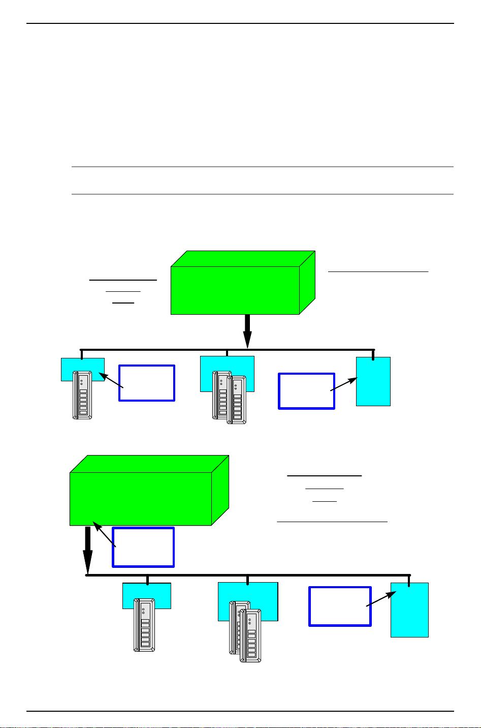
LNL-1000 Intelligent System Controller
Intelligent System Controller
Downstream Communications
• Four 2-wire ports
• Two 4-wire ports
• Combination 2 and 4 wire ports
32 Downstream
Devices
Total
Single Reader
Interface Module
Dual Reader
Interface Module
Input/Output
Control
Module(s)
RS-485
Multi-drop
2 or 4 wire
EOL
Termination
Required
EOL
Termination
Required
01
23
45
67
89
*
#
01
23
45
67
89
*
#
01
23
45
67
89
*
#
Intelligent System Controller
Downstream Communications
• Four 2-wire ports
• Two 4-wire ports
• Combination 2 and 4 wire ports
32 Downstream
Devices
Total
Single Reader
Interface Module
Dual Reader
Interface Module
Input/Output
Control
Module(s)
RS-485
Multi-drop
2 or 4 wire
EOL
Termination
Required
EOL
Termination
Required
01
23
45
67
89
*
#
01
23
45
67
89
*
#
01
23
45
67
89
*
#
which marks the state of the signal being sent and allows the line to flow for reliable communications. This
is true for most devices that are used for Host to ISC communications, but any device that has been approved
by Lenel will indicate how termination should be configured for proper operation in its documentation.
15.2.3 RS-485 Cable Termination from ISC to Downstream Modules
Termination of this section of the RS-485 bus always remains the same. Each end of the RS-485 bus must be
terminated using the on-board jumpers provided with each piece of hardware. Please refer to the termination
drawings for each component being installed in this hardware manual.
Note: This applies to ports 2, 3, 4, and 5.
Typical Downstream Communication Configuration
(note where EOL terminators are required)
90 — revision 7
Page 91

16 Maintenance
ABC
Hardware Installation Guide
Refer to
firmware.
Firmware Updates in the Hardware Installation Guidelines section for instructions for downloading
16.1 Verification
The ISC board contains three Status LEDs (LED A, LED B, LED C) that can be used to verify correct
installation after power up.
The following chart describes the purpose of each LED on the ISC board.
LED Purpose
A This LED blinks rapidly whenever the ISC is powered up and is operating normally.
B This LED is on when upstream communication to host computer is in process.
C This LED is on when downstream communication to reader interfaces or input/
output modules is in process.
16.2 Replace Memory Backup Battery
The ISC contains a Memory Backup battery that is used to backup configuration data and event buffer data
in the event of a power failure.
A 3V lithium ion battery (Rayovac BR2325 or Wuhan Lixing CR2330) is used for the Memory Backup.
This battery should be replaced annually.
Caution: There is a danger of explosion if battery is incorrectly replaced. Replace only
with the same or equivalent type recommended by the manufacturer. Dispose of
used batteries in accordance with the manufacturer's instructions.
revision 7 — 91
Page 92

LNL-1000 Intelligent System Controller
17 Specifications
The ISC is for use in low voltage, class 2 circuits only.
• Primary Power: (DC or AC)
- DC input: 12 VDC ± 15%. 350mA
- AC input: 12 VAC ± 15%. 600mA RMS
• Memory and Clock Backup: 3 V lithium, type BR2325
• Communication Ports:
- Port 1: RS-232 or RS-485 (2-wire or 4-wire), 9600 to 38400 bps async
- Ports 2-5: RS-485 (2-wire or 4-wire), 9600 to 38400 bps async
• Inputs:
- Cabinet Tamper Monitor: unsupervised, dedicated
- Power Fault Monitor: unsupervised, dedicated
• Wire Requirements:
- Power: 1 stranded twisted pair, 18 AWG
- RS-485: 24 AWG stranded twisted pair(s) with shield, 4000 feet (1219 m) maximum
- RS-232: 24 AWG stranded, 50 feet (15.24 m) maximum
- Inputs: stranded twisted pair, 30 ohms maximum
• Environmental:
- Temperature: Operating: 0° to 70° C (32° to 158° F)
- Humidity: 0 to 95% RHNC
• Mechanical:
- Dimension: 6 in. (152 m) W X 8 in. (203 mm) L X 1 in. (25 mm) H
- Weight: 10 oz. (290 g) nominal
• Certifications:
- UL294 & UL1076 Listed
-ULC Listed
-FCC Part 15
- FIPS 197 Certificate #306
-CE marking
- RoHS compliant
- WEEE
Note: These specifications are subject to change without notice.
92 — revision 7
Page 93

LNL-2000
INTELLIGENT
SYSTEM
CONTROLLER
Page 94

Page 95
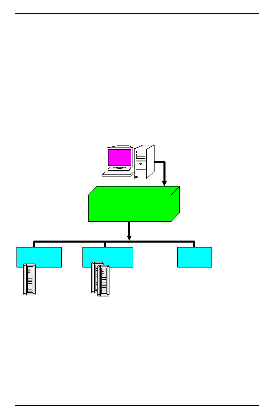
Hardware Installation Guide
Access
Control
System
Intelligent System
Controller
Dual Reader
Interface Module
Single Reader
Interface Module
Input/Output
Control
Module(s)
32 Downstream
Devices Total
Dual Path
Communications
from Host to Controller
RS-232,
RS-485, Ethernet, Dial-Up,
Token Ring, etc...
Downstream Communications
Four 2-wire ports
Two 4-wire ports
Combination 2 and 4 wire ports
Up to 32 Single
Reader
Interface Modules
(32 Readers)
Up to 16 Output Control Modules
Up to 16 Alarm Input Control Modules
RS-485
Multi-drop
2 or 4 wire
01
23
45
67
89
*
#
01
23
45
67
89
*
#
01
23
45
67
89
*
#
Interface Modules
Up to 32 Dual
Reader
(64 Readers)
18 Overview of the LNL-2000
This installation guide is intended for use by technicians who will be installing and maintaining the
LNL-2000 Intelligent System Controller (ISC).
The LNL-2000 provides the real time processing for the I/O interfaces connected to it. It holds the database
for the subsystem configuration and cardholders, the event log buffer in battery-backed memory.
18.1 Interfaces
The ISC interfaces upstream with the Access Control software on a host system and downstream with the
following Lenel field hardware components.
LNL-2000 Communications Overview
revision 7 — 95
Page 96
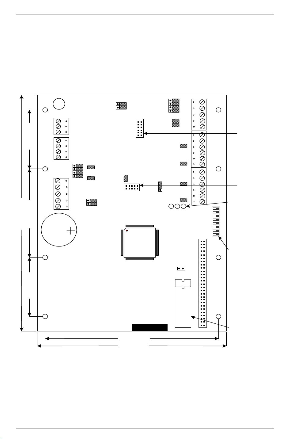
LNL-2000 Intelligent System Controller
ACDC
AC
GND
Battery
GND
GND
IN2
IN1
TXD6
TR6+
RXD6
TR6-
RTS6
R6+
CTS6
R6-
GND
TXD1
TR1+
RXD1
TR1-
RTS1
R1+
CTS1
R1GND
TR2+
TR2-
GND
TR3+
TR3-
GND
TR4+
TR4-
GND
TR5+
TR5-
GND
1 2 3 4 5 6 7 8
A B C
SN
485 232
4W 2W
485 232
J12
J2
5.50" (139.7)
6.00" (152.4)
2.00" (50.8) 2.00" (50.8)3.00" (76.2)
8.00" (203.2)
STATUS LED
DIP
SWITCHES
PROGRAM
PROM
J27
J8
J5
J4J6J7
J10
J9
J11
TB1TB2
J21
J22
J23
J24
J25
3
2
1
J26
115K
57K
TB3
S1
J3U11
J17
J14
4W 2W
485 232
485 232
J18
J20
J16
J19
J13
J15TB6
TB5
J12: MOUNTING
PIN BLOCK FOR
MSS-LITE
J27: MOUNTING
PIN BLOCK FOR
COBOX-MICRO
18.2 The LNL-2000 Board
The ISC board contains the following components: two (2) unsupervised alarm inputs, two (2) RS-232 or
RS-485 interface, four (4) RS-485 interfaces (which can consist of four 2-wire, two 4-wire, or one 4-wire
and two 2-wire interfaces), one (1) power-in input, eight (8) DIP switches, and twenty-three (23) jumpers. It
also contains a set of three (3) status LEDs and one (1) memory backup (3 volt lithium) battery.
LNL-2000 board
96 — revision 7
Page 97
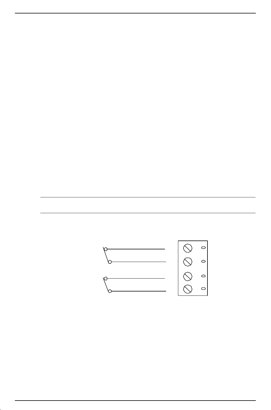
Hardware Installation Guide
GND
IN 2
GND
IN 1
CABINET
TAMPER
POWER
FAULT
19 Installation
To install the ISC, perform the installation procedures described in the following sections, in the order in
which they are presented.
1. Wire the unsupervised alarm inputs for power fault and cabinet tamper monitoring.
2. Wire the upstream host communication.
3. Wire the downstream device communication.
4. Wire the power input.
5. Remove the plastic safety strip from the memory backup battery.
19.1 Wiring
19.1.1 Unsupervised Alarm Inputs: Power Fault and Cabinet Tamper
Monitors
The LNL-2000 features two alarm inputs that can be used for power fault and cabinet tamper monitoring.
These inputs are connected using the Input 2 (IN2) and Input 1 (IN1) contact terminals on the ISC board.
Input 2 and Input 1 are both simple N/C (normally closed) contact closure monitors.
Note: If either of these inputs is not used, a shorting wire should be installed.
Unsupervised Alarm Input Wiring
19.1.2 Upstream Host Communication
Configuration data and event/status reports are communicated via port 1 (primary) or port 6 (secondary), the
host ports. RS-232 interface is for direct one to one connection to a host computer port, via modem or a
plug-in ethernet module. When the ethernet module is used, port 1 must be configured as a RS-232 interface.
I/O devices are connected via port 2 through port 5.
Port 1 may be set up as a RS-232 interface or a RS-485 interface. RS-485 interface may be 2-wire or 4-wire
type.
revision 7 — 97
Page 98

LNL-2000 Intelligent System Controller
Port 6 may be set up as RS-232 interface or a RS-485 interface. RS-485 interface may be 2-wire or 4-wire
type.
Direct-connect RS-232 cables should be no longer than 50 feet. Leased lines or fiber optics can also be used.
RS-232 Communications
The RS-232 communications interface is for short distance wiring or point to point communications. A
number of products provide RS-232 interfaces such as connections to modem, PC, etc. This interface is
intended for a short distance communication because its high impedance is more susceptible to noise. Cable
length is generally limited to 50 feet (15.24 m). If required, this distance may be extended to a few hundred
feet by using low capacitance shielded cables. The optimal cable is a (Belden 9610) or equivalent wire.
For direct connections (via RS-232) between the LNL-2000 and the host, 115,200 baud is not recommended
unless the third-party hardware devices used support a CTS/RTS hardware handshake at the UART level.
The Microsoft serial device drivers do not support hardware handshaking at this level. The 115,200 baud
rate can be used for the RS-232 connection between the LNL-2000 and the Lantronix devices that support
115,200 baud.
RS-485 Communications
The (EIA) Electronic Industries Association standard defines RS-485 as an electrical interface for multi-port
communications on a bus transmission line. It allows for high-speed data transfer over extended distance
(4000 feet/1219 m). The RS-485 interface uses a balance of differential transmitter/receiver to reject
common mode noise. For increased reliability over the extended distances End-of-line (EOL) termination is
required.
RS-485 communication requires a 24 AWG (minimum) twisted pair (with shields) cable. Either a 2-wire or
4-wire RS-485 cable configuration can be used. The RS-485 cable should be no longer than 4000 feet (1219
m), 100 ohms minimum impedance (Belden 9842 4-wire or 9841 2-wire, plenum cabling Belden 88102,
West Penn, or equivalent). Install a termination jumper only for end of line unit(s).
When connecting to the host via RS-485 (2-wire or 4-wire), do not use the 115,200 baud rate because there
is no hardware handshake capability. For reliable communication with this baud rate, CTS on the host must
be connected to RTS on the controller; RS-485 communication does not provide this.
When connecting a controller to a Lantronix device, do not use RS-485 communication. This particular
configuration also lacks hardware handshake signals. RTS on the Lantronix must be connected to CTS on
the controller. At 115,200 baud, CTS on the Lantronix must be connected to RTS on the controller as well,
which is not provided via RS-485.
RS-485 Line Termination
RS-485 (2-wire or 4-wire) must be terminated at both ends of the RS-485 line (bus). Terminating the line
provides a more reliable communication by minimizing the signal reflection and external noise coupling.
98 — revision 7
Page 99
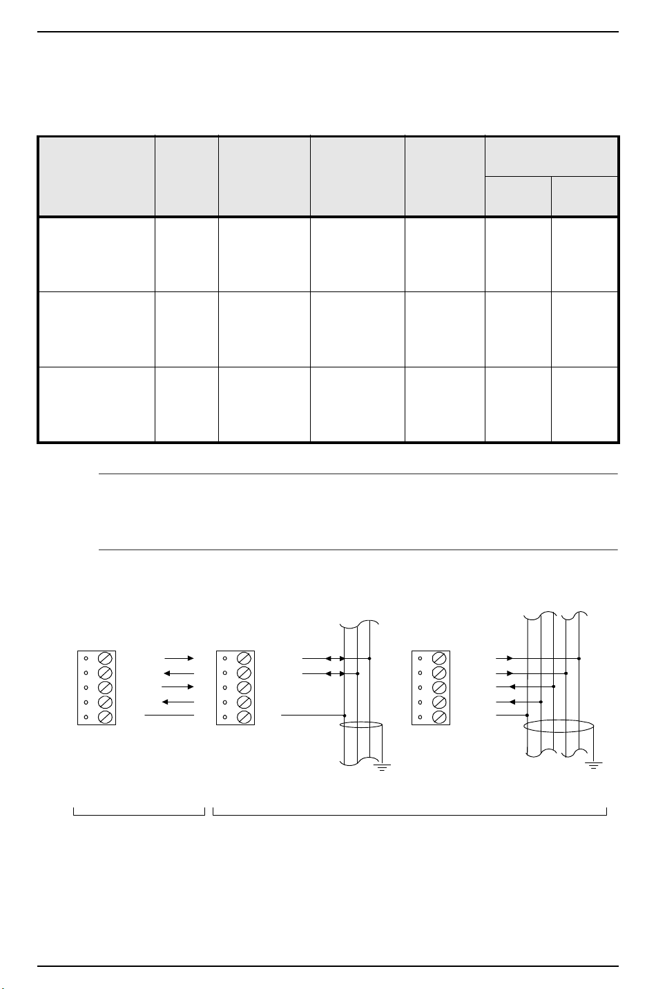
Hardware Installation Guide
TXD/TR1+
RXD/TR1-
RTS/R1+
CTS/R1-
GND
TXD/TR1+
RXD/TR1-
RTS/R1+
CTS/R1-
GND
TXD/TR1+
RXD/TR1-
RTS/R1+
CTS/R1-
GND
PORTS (1 & 6)
CONFIGURED AS RS-232
(Wire with 24 AWG stranded)
2-WIRE
4-WIRE
PORTS (1 & 6) CONFIGURED AS RS-485
(Wire with 24 AWG stranded twisted pair(s) with shield)
Earth
Ground
Earth
Ground
Each component provided has an on-board termination. It is up to the installer to determine which device is
at the end of the communication line.
Belden Wire Specifications
Trade Number
UL NEC Type
CSA
Certification
9841
NEC CM CSA
Numbe
r of
Pairs
Nominal
D.C. R.
Conductor
1 24.0 ohms/M
78.7 ohms/
Shield Nominal
Impedance
(Ohms)
3.35 ohms/M
120 12.8 42
11.0 ohms/K
Nominal
Capacitance
pF/feet pF/
meter
km
9842
NEC CM CSA
2 24.0 ohms/M
78.7 ohms/
2.2 ohms/M
7.2 ohms/K
120 12.8 42
km
88102
NEC CMP CSA
2 24.0 ohms/M
78.7 ohms/
15.5 ohms/M
50.9 ohms/km
100 12.95 42
km
Notes: If RS-485 communication is used, an RS-232 to RS-485 converter is required at the host
workstation. Use part # HO-2064.
The 2-wire configuration is recommended over the 4-wire for RS-485.
Upstream Host Communication Wiring
revision 7 — 99
Page 100
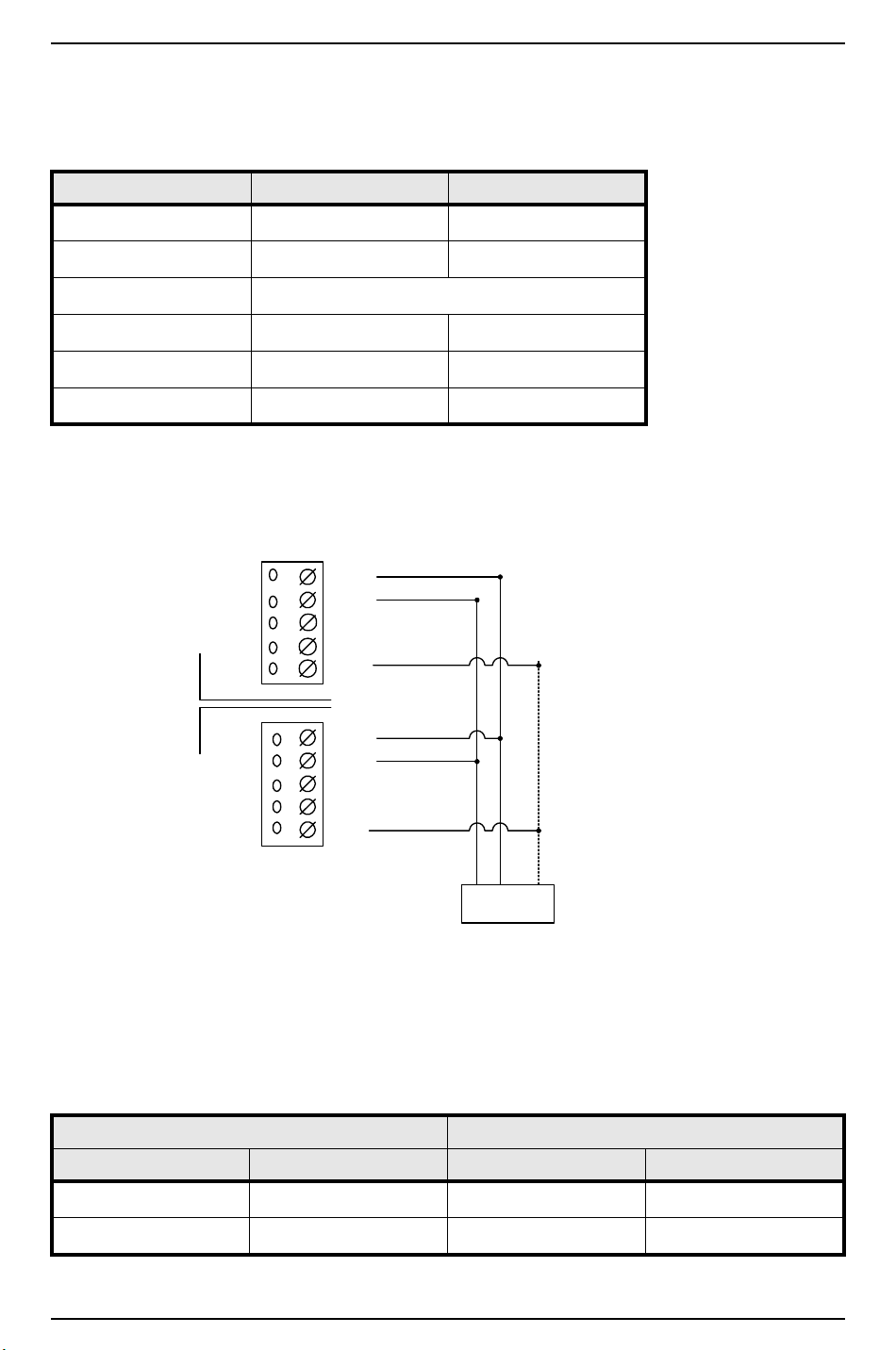
LNL-2000 Intelligent System Controller
TR1+
TR1-
GND
R1 -
R1 +
TR1+
TR1-
GND
R1 -
R1 +
ISC Panel 2,
Address 01
ISC Panel 1,
Address 00
2-WIRE MULTIDROP RS-485 FROM HOST
(Maximum of 8 control panels)
2 3 5
DB9-pin
Connector
(Jumper Wires
4,6,8 Together)
TO CONTROL ROCKET PORT HO-2062
COMBO BOARD (PORTS 1 AND/OR 2)
Ports 1 and 6-wiring configuration. This configuration will work for Direct connect (RS-232) and Lantronix
Ethernet network communications. With direct connect and with Lantronix, DIP Switch 5 needs to be ON
using connection cables provided by Lenel.
ISC 9-pin connector 25-pin connector
TXD/TR1+ pin 2 pin 3
RXD/TR1- pin 3 pin 2
RTS/R1+ This is used for 115,200 baud rate.
CTS/R1- pin 7 pin 4
GND pin 5 pin 7
Jumper together 4,6 & 8 5,6 & 20
2-Wire RS-485 from Host
Wire Configuration- Switch #5 must be off for all panels in this configuration.
Panel 1 Panel 2
Jumper Setting Jumper Setting
J4, J6, J7, J10 ON pin 1 & 2 J4, J6, J7, J10 ON pins 1 & 2
J8 ON 2W pins 2 & 3 J8 ON 2W pins 2 & 3
100 — revision 7
 Loading...