

Page 1
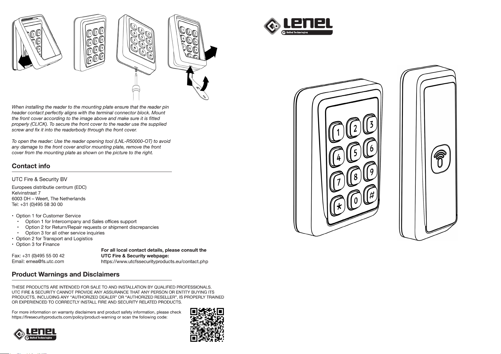
Quick Installation Guide
Lenel Readers - 5000 Series
Supervised F/2F
Quick Installation Guide
Lenel Readers - 5000 Series
Supervised F/2F
Page 2
Quick Installation Guide
Lenel Readers - 5000 Series Standard 13,56MHz/125kHz
Supervised F/2F
Please note that this is only a quick installation guide.
Information regarding recommendations, measurements and accessories are
available in the full version of the Lenel Readers - 5000 Series installation guide.
P4 P5
T/GPIO3
GPIO1
GPIO2
GND
B/RX
A/TX
GND
DC+
Quick Installation Guide
Lenel Readers - 5000 Series
Slimline 13,56MHz
Supervised F/2F
P5
K-LED
BZ CTRL
R-LED
G-LED
D-/TX
D0
D1
D+/RX
T/GPIO3
GPIO1
GPIO2
GND
B/RX
A/TX
GND
DC+
P4
D+/RX
D1
D0
D-/TX
G-LED
R-LED
BZ CTRL
K-LED
Power consumption:
Model Current draw (idle1) Current draw (peak
12V 24V 12V 24V
Standard 13.56MHz/125kHz 90 mA 45 mA 159 mA 89 mA
Slimline 13.56MHz T.B.C. mA T.B.C. mA T.B.C. mA T.B.C. mA
1 Current draw does not include heater nor BLE antenna consumption.
2 LED settings; LED Bar = Low, Back Light = Low
Please consult table in full installation manual for more information on heater
consumption settings and how the LED-settings will aect current draw.
1,2
)
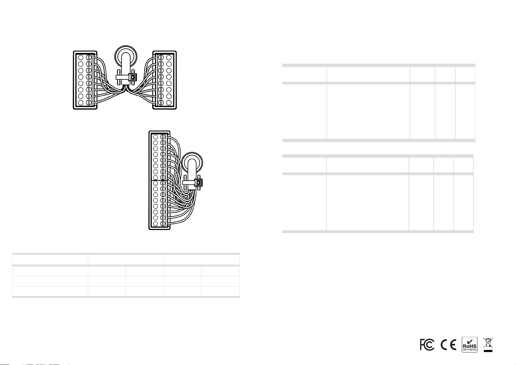
Terminal description
P4
PIN
T/GPIO3
GPIO1
GPI/O2
GND
B/RX
A/TX
GND
DC+
Description
Tamper output / General purpose I/O
General purpose I/O
General purpose I/O
Ground
RS485 - / OSDP
RS485 + / OSDP
Power supply
Power supply 9 - 30 VDC
P5
PIN
D+/RX
D1
D0
D-/TX
G-LED
R-LED
BZ CTRL
K-LED
Notes
1. Maximum wiegand cable length is 150 meters and requires a high quality shielded cable with
minimum AWG18 dimension (=0.8231mm2) in an environment free from electrical noise. A cable
with smaller dimension or an installation environment with electrical disturbances will reduce the
maximum cable length.
2. Wiegand requires dedicated wires for external control of Green LED, Red LED, Buzzer and
Keypad backlight.
3. When utilizing the GPI/O’s, each respective GPI/O1, GPI/O2 or GPI/O3 must be connected to
each respective pin and also to GND. The general purpose input/output will only be activated if so
applied in the reader configuration.
4. RS 485/OSDP requires twisted pair cable.
5. Maximum Supervised F2/F cable length is 915 meters and requires a high quality shielded cable
with minimum AWG20 dimension (=0.5176 mm2) in an environment free from electrical noise with
12V signal amplitude from controller.
6. 4-state Supervised F/2F requires 2pcs 1kOhm resistors, Exit button must be connected to
K-LED and GND and Door sensor must be connected to BZ CTRL and GND. See full version of the
installation guide for wiring diagram.
Description
Secondary RS485 +
Wiegand Data1
Wiegand Data0
Secondary RS485 -
External Green LED control
External Red LED control
External Buzzer control
External keypad LED control
Wiegand
x
-
-
-
-
-
x
x
Wiegand
-
x
x
-
x
x
x
x
RS485/
OSDP
-
-
-
-
x
x
x
x
RS485/
OSDP
-
-
-
-
-
-
-
-
F/2F
-
-
-
-
-
-
x
x
F/2F
-
x
-
-
x
-
-
-
 Loading...